tfsi engines of 1.8 l and 2.0 l of the audi ea888 line ... 606 - audi 1,8l- and 2.0l tfsi engines of...
TRANSCRIPT

Audi
Audi
The advance in technology
Training Service
606
TFSI engines of 1.8 l and 2.0 l of the Audi EA888 line
(3rd generation)
Subject to all rights and modi fi cations.
Copyright
AUDI AG
I / VK-35 [email protected]
AUDI AG
D-85045 Ingolstadt De fi nition technical 11/12
Printed in Germany A12.5S00.90.40
Self-Study Programme 606
For internal use

2
e-media
This self-study program includes QR codes allowing you
to access additional interactive media, cf. "Information on
QR codes" on page 63.
Ingolstadt engineers have, during development, paid particular attention to the following
points:
• large number of identical parts for all engine versions
• Reduction in engine weight
• Reduction of engine internal friction
• Increased power and torque accompanied by a reduction in consumption
• Improved comfort features. In addition, the motors must be implemented in all
markets, including those in fuel quality is poorer. The "global engine" also plays an
important role for increasing hybridization.
You will find the precise technical description of engine development level 0 in the
self-study program 384 "engine TFSI 4-cylinder 1.8l Audi chain drive." You can notify
you of changes between the development level 0 and 1 and 2 levels of development in
the self-study program 436 "Changes to the engine TFSI 4-cylinder chain drive."
educational objectives of this self-study program:
This self-study program aims to familiarize yourself with the engine technical TFSI
4-cylinder EA888 engine line (3rd generation). It focuses on the TFSI engine technology
1.8l. After processing this self-study program, you will answer the following questions:
• What are the main technical measures carried out during the development of the
line of EA888 engines?
• How do new innovative technologies?
• What's new in the service area and service?
New innovative technologies implemented are:
• manifold integrated into the cylinder head exhaust
• dual injection system with direct injection in the intake manifold
• new compact turbocharger module with turbine housing cast iron, electric
wastegate actuator and lambda probe upstream of the turbine
• Innovative thermal management with full electronic control of the coolant
Audi move to the third generation of its four engines EA888 success cylinders. The
reasons for the new phase of development is emission standards more stringent (Euro 6)
and, of course, consumption reduction requirements, accompanied by a reduction in CO
emissions 2. The powertrain was in all respects redesigned from top to bottom.emissions 2. The powertrain was in all respects redesigned from top to bottom.emissions 2. The powertrain was in all respects redesigned from top to bottom.
In addition to downsizing the downspeeding * playing an increasing role. The "global In addition to downsizing the downspeeding * playing an increasing role. The "global In addition to downsizing the downspeeding * playing an increasing role. The "global
engine" is produced at the factory Audi engines of Györ, Silao (Mexico) as well as in
China. Here, the EA888 engine line is produced in Shanghai and Dalian will also
subsequently produced in Changchun. Like its predecessor, the engine is available with a
displacement of 1.8 l and a displacement of 2.0 liters. It is used on car platforms and
brands of the most diverse group. The range of engine performance is very broad.
1.8l TFSI engine
606_001

3
Note
return
The self-study program provides basic notions of design and function of new vehicle models, new vehicle components or new technologies.
The Self-Study Programme is not a repair manual! The values shown are for information only and refer to the software version valid in the drafting of the
self-study program.
For maintenance and repair, please refer to the current technical documentation. Please refer to the glossary at the end of this self-study program, an explanation of
all terms in italics and marked with an asterisk.
Introduction
Design Goals 4 ____________________________________________________________________________________________________________________________________ brief technical description
___________________________________________________________________________________________________________________________ 5 Technical features
___________________________________________________________________________________________________________________________________ 6
engine mechanics
Overview _____________________________________________________________________________________________________________________________________________ 8 Cylinder Block 8
________________________________________________________________________________________________________________________________________________ oil Carter
________________________________________________________________________________________________________________________________________________ 9 Mobile Crew (1.8l TFSI engine)
_________________________________________________________________________________________________________________10 command chain
_____________________________________________________________________________________________________________________________________12 trees ofbalancing
_______________________________________________________________________________________________________________________________________13 Support ancillaries
_____________________________________________________________________________________________________________________________14
______________________________________________________________________________________________________________________________________________________15 integrated cylinder head exhaust manifold (IAGK)
_______________________________________________________________________________________________________________18 degassing housing and crankcase gases
_____________________________________________________________________________________________________20integrated exhaust (IAGK) _______________________________________________________________________________________________________________18 degassing housing and crankcase gases _____________________________________________________________________________________________________20
Oil supply
System overview ____________________________________________________________________________________________________________________________________24 oil supply
______________________________________________________________________________________________________________________________________26 oil filler cap
__________________________________________________________________________________________________________________________28 Switchable piston cooling Injectors
________________________________________________________________________________________________28
Cooling system
Synoptic ____________________________________________________________________________________________________________________________________30 innovative thermal management system (ITM)
______________________________________________________________________________________________________________________32
air and boost supply
System overview ____________________________________________________________________________________________________________________________________40 air guidance on engine in a
transverse position ________________________________________________________________________________________________41 air guidance on engines longitudinal position
_______________________________________________________________________________________________42 Intake Manifold Turbocharger
______________________________________________________________________________________________________________________________________43
_________________________________________________________________________________________________________________________________________44
fuel supply system
System overview ____________________________________________________________________________________________________________________________________48 Packaging mixing / dual
injection system __________________________________________________________________________________________49 modes
________________________________________________________________________________________________________________________________50
Engine management
Synoptic TFSI engine system 1.8l CJEB (Audi A5 12) ______________________________________________________________________________________52
Differentiation Engine Versions
Differences between 1.8 l / 2.0 l and between longitudinal and transverse position _______________________________________________________________54 differences between components
longitudinal and transverse position ___________________________________________________________________________55 differences between components displacement of 1.8 l and 2.0 l
_____________________________________________________________________________________56 Differences in turbochargers
__________________________________________________________________________________________________________58 combustion process differences
________________________________________________________________________________________________________________59
Annex
Service Glossary _______________________________________________________________________________________________________________________________________________________60
____________________________________________________________________________________________________________________________________________________62 self-study programs (SSP)
______________________________________________________________________________________________________________________63 Information on QR codes
____________________________________________________________________________________________________________________________63
Summary

4
return
You can find more information about the design and operation as well as the stages of development in the self-study program 384 "engine TFSI 4-cylinder 1.8l
Audi chain control" and the self-study program 436 "Changes to the engine TFSI 4 chain drive cylinders ".
CO reduction 2CO reduction 2
To meet the limit values of exhaust gases set by the Euro 6 standard and reduce CO 2 we To meet the limit values of exhaust gases set by the Euro 6 standard and reduce CO 2 we To meet the limit values of exhaust gases set by the Euro 6 standard and reduce CO 2 we
had to make the following enhancements and changes.
Adaptation to the modular platform
To use the third generation of the line of EA888 engines as "global engine" in the
longitudinal modular platform (MLB) and the transverse modular platform (MQB), we
had to revisit its ratings and its attachment and connection.
Design Goals
When developing the 3rd generation of the line of EA888 engines, achieving exhaust
limit values recommended by the Euro 6 standard and suitability for use in modular
platforms were the main items on the agenda .
When optimizing the basic engine, reduction of weight and the friction must be taken
into account.
When the engine is operated in a transverse position, a call is made to an engine
support and an oil gauge. When the engine is mounted longitudinally mounted, it uses
the engine and support for a sealing cap in place of the oil dipstick.
Reducing friction
The chain adjusters are optimized for low oil pressure. The clamping force has also
been reduced. A reduction in consumption by friction has been possible.
Furthermore, the crankshafts were executed with smaller bearing diameters, generate
less friction.
The design of the belt drive is identical in the case of the longitudinal position as
transverse. Alternators and air conditioning compressors, however, remain dedicated to
the vehicle.
Downsizing / Downspeeding
• Drive camshafts of intake and exhaust
• Audi valvelift system (AVS)
friction and weight reduction
• balancer shafts with friction bearings in part
• Diameters smaller crankshaft bearing
• reduced oil pressure level
• Reduction of tension strength in the secondary control
Cylinder head
• Cylinder head with integrated exhaust manifold
• Carter eased turbocharger
• electric wastegate actuator
Injection
• ISPs and MPI injectors
thermal management
• Control via rotary valve
Introduction

5
brief technical description
Engine Type
• petrol inline four-cylinder direct injection engine
• Turbocharging with cooling of the charge air
• Chain drive
• balancer shafts
Valvetrain
• Four valves per cylinder, two overhead camshafts (DOHC)
• continuously variable timing camshaft intake and exhaust
• Audi valvelift system (AVS)
• Engine management Simos 12 (sté Continental)
• start-stop system and recuperation
Packaging mixture
• Management of full electronic engine with electric throttle
• direct injection and injection in the intake pipe combined
• lambda adaptive control
• Mapping static ignition distribution of high voltage
• selective adaptive knock detection
606_008
1.8l TFSI engine
Torque curve and power
Motor with letters benchmark engine CJEB
Power in kW
Torque Nm
Speed [r / min]
606_057
e-media
Animation for the entire engine.

6
technical features
Motor letters benchmark CJEB CJSA CJSB
Mounting position longitudinal transversal transversal
Displacement in cm 3 Displacement in cm 3 Displacement in cm 3 1798 1798 1798
Power kW to rev / min Power kW to rev / min 125-3800 - 6200 132-5100 - 6200 132-4500 - 6200
Couple in Nm r / min Couple in Nm r / min 320-1400 - 3700 250-1250 - 5000 280-1350 - 4500
bore in mm bore in mm 82.5 82.5 82.5
Race in mm Race in mm 84.1 84.1 84.1
Compression 9.6: 1 9.6: 1 9.6: 1
crank shaft
crankshaft bearing diameter in mm crankshaft bearing diameter in mm 48 48 48
Engine management
Fuel RON Fuel RON 95 1), 2) 95 1), 2) 95 1), 2) 95 1), 2) 95 2)95 2)
maximum injection pressure barmaximum injection pressure bar
CO 2 in g / kmCO 2 in g / kmCO 2 in g / km
emissions standard Euro5 Euro5 more Euro5 more
Ignition order 1-3-4-2 1-3-4-2 1-3-4-2
Knock control Yes Yes Yes
overeating Yes Yes Yes
Recirculation of exhaust gas internal (variable valve timing
system)
internal (variable valve timing
system)
internal (variable valve timing
system)
Intake manifold flaps Yes Yes Yes
Change the setting of the inlet side distribution Yes Yes Yes
Change the setting of the exhaust side distribution Yes Yes Yes
High-pressure injectors (ISP) Yes Yes Yes
Injectors in the intake manifold (MPI) Yes Yes Yes
secondary air system no no no
Audi valvelift system (AVS) in the exhaust Yes Audi valvelift system (AVS) in the exhaust Yes Yes Yes
rotary vane Yes Yes Yes
Oil pump control Yes Yes Yes
Tumble Yes Yes Yes
Drumble 4) Drumble 4) no no no
1) Unleaded petrol RON 91 permitted, but however with loss of power1) Unleaded petrol RON 91 permitted, but however with loss of power
2) E25-compatible (from the date of manufacture wk. 40/2012)2) E25-compatible (from the date of manufacture wk. 40/2012)
3) Super unleaded 95 RON authorized, but however with loss of power3) Super unleaded 95 RON authorized, but however with loss of power
4) Drumble see page 594) Drumble see page 59
1.8l TFSI engine

7
Motor letters benchmark CNCB CNCD CJXC
Mounting position longitudinal longitudinal transversal
Displacement in cm 3 Displacement in cm 3 Displacement in cm 3 1984 1984 1984
Power kW to rev / min Power kW to rev / min 132-4000 - 6000 165-4500 - 6250 221-5500 - 6200
Couple in Nm r / min Couple in Nm r / min 320-1500 - 3800 350-1500 - 4500 380 to 1800 - 5500
bore in mm bore in mm 82.5 82.5 82.5
Race in mm Race in mm 92.8 92.8 92.8
Compression 9.6: 1 9.6: 1 9.3: 1
crank shaft
crankshaft bearing diameter in mm crankshaft bearing diameter in mm 52 52 52
Engine management
Fuel RON Fuel RON 95 1), 2) 95 1), 2) 95 1), 2) 95 1), 2) 95 1), 2) 98 2), 3) 98 2), 3)
maximum injection pressure barmaximum injection pressure bar
CO 2 in g / kmCO 2 in g / kmCO 2 in g / km
emissions standard Euro5 Euro5 Euro6
Ignition order 1-3-4-2 1-3-4-2 1-3-4-2
Knock control Yes Yes Yes
overeating Yes Yes Yes
Recirculation of exhaust gas internal (variable valve timing
system)
internal (variable valve timing
system)
internal (variable valve timing
system)
Intake manifold flaps Yes Yes Yes
Change the setting of the inlet side distribution Yes Yes Yes
Change the setting of the exhaust side distribution Yes Yes Yes
High-pressure injectors (ISP) Yes Yes Yes
Injectors in the intake manifold (MPI) Yes Yes Yes
secondary air system no no no
Audi valvelift system (AVS) in the exhaust Yes Audi valvelift system (AVS) in the exhaust Yes Yes Yes
rotary vane Yes Yes Yes
Oil pump control Yes Yes Yes
Tumble no no no
Drumble 4) Drumble 4) Yes Yes Yes
2.0l TFSI engine
8
Overview
At the cylinder block, not only the weight has been significantly reduced, but a second
pressurized oil gallery was developed the "cold side" for piston cooling nozzles to
electrical switching. Changes were made to the sections of the coolant and oil return and
position of the knock sensors has also been optimized.
For the balance shafts are sufficiently robust for the implementation of a start-stop
system, they are partly executed with anti-friction bearings. They thus feature in a
point of a smooth bearing and two points of antifriction bearings. Simultaneously, the
friction, the weight and inertia of the balance shafts were reduced. The oil return of the
"hot" side of the engine has been completely overhauled.
Cylinder Block
The cylinder block has been fundamentally redesigned. The main objective was to
reduce weight. The wall thickness is increased from approx. 3.5 mm to 3.0 mm. In
addition, the function of crude oil separator has been integrated into the cylinder block.
In total, it was possible to gain 2.4 kg at the cylinder block to the motor of the 2nd
generation. Consumption by internal friction was also reduced. The main measures
taken for this are reducing crankshaft bearing diameters and improved fixation of the
balance shafts.
Other modifications to the engine of the second generation:
• second oil gallery pressure in the region of the "cold side" for the piston cooling
nozzles electrically commutated
• Modifications sections of coolant and oil return
• shirt optimized long coolant
• supply of the oil cooler via the cylinder head coolant return
• Optimized position of knock sensors
• fixing improved bearings of the balance shafts
The drive shaft output side sealing is achieved by a sealing flange. The latter has a
liquid sealant and screwed onto the cylinder block with aluminum screws.
The timing case cover is sealed with liquid sealant.
Weatherization
weight reduction measures (1.8l TFSI engine)
In the case of the third generation of the line of EA888 engines, a reduction in the total
weight of about 7.8 kg was performed. To achieve this, the following components have
been optimized or are used for the first time:
• Cylinder Block with thin walls and removal of coarse oil separator
• Cylinder head and turbocharger
• Crankshaft (with diameters smaller crankshaft bearings and four
counterweight)
• Upper oil pan in cast aluminum (aluminum with screw)
• Bottom plastic oil sump
• Aluminum Screw
• balancer shafts (with friction bearings in part)
engine mechanics

9
606_028
Timing case cover
Cylinder Block Cast iron oil pressure
switch, level 3 F447 sensor rattle 1 G61
sealing flange, drive shaft output side
upper sump with baffle
regulated oil pump oil pressure regulating
valve N428
Insert honeycomb
level transmitter and G266
oil temperature
Bottom of sump engine speed sender G28
joint
upper part of the oil pan
It is made of die-cast aluminum. The oil pump and insert Honeycomb for suction and
return oil are screwed there. Pressurized oil channels and the control valve of the oil
pump at two levels are also housed in the upper part of the oil pan.
Sealing to the cylinder block is made with liquid sealant. Aluminum screws are used
for screwing.
To further improve the acoustic properties of the engine, the bearing caps are screwed
onto the upper part of the oil sump.
oil pan
Bottom of the oil pan
The bottom of the oil sump is made of plastic. This has saved about 1.0 kg. Sealing is
provided by a molded rubber seal. The screwing is carried out with steel screws.
The level transmitter of oil and G266 oil temperature is mounted in the bottom of the oil
sump. The oil drain plug is made of plastic (bayonet).
Overview

10
moving equipment (1.8l TFSI engine)
In the area of the crankshaft, the main objectives of development were reducing the
weight and the friction.
Link (execution fractured head)
Circlip
Lower connecting rod bearing
Connecting rod bearing
upper piston shaft
Piston
crank shaft
rod cap
606_030
e-media
Animation for the moving element and the control by
silent chain as well as the drive of the oil pump control
and the coolant pump.

11
Piston
Here, the piston clearance was increased to reduce friction during the action phase. It is
also used a material resistant to the wear of the piston skirt.
piston ring upper segment conical = / on
2,0l engines
Segment rectangular section, asymmetrical
convex
central piston ring = Shouldered conical Segment
Segment = lower piston oil ring (in two parts,
spiral spring wiper)
Crankshaft (1.8l TFSI engine)
Relative to the engine of the second generation, the diameters of the crankshaft
bearings have been reduced from 52 to 48 mm and the number of counterweights
reduced from eight to four. This has saved 1.6 kg. Bearing caps, superiors as inferiors,
are lead-free bearings bilayer. The ability to start-stop mode is ensured.
Rod / piston pin
The connecting rods are kind of broken. In the lower foot rod, a call is made, as in the
case of main bearings, with two-material bearings.
A key new feature is the removal of the bronze ring in the side of upper rod.
The entire motor is equipped with bearings lead-free. Fixing without gudgeon ring is
used for the first time on the VL engines. This is a process patented by Audi. The piston
pin is connected directly to the steel in the rod and to the aluminum alloy in the piston.
The piston pin is why with a special surface coating. This is a coating DLC *.The piston pin is why with a special surface coating. This is a coating DLC *.
606_027
lower half range of crankshaft bearing
upper part of the oil pan
Screwing below
Cylinder Block
lower half range of crankshaft bearing
lateral screw
The crankshaft bearing caps are screwed with the upper oil pan. This measure
improves engine comfort properties in terms of vibration behavior and acoustics.

12
Chain drive
The basic architecture of the chain drive is widely resumption of the 2nd generation. It
has also been consistently improved. Due to the reduction in consumption by friction and
reduced need for oil, the drive power in the chain drive is also reduced. Therefore an
adjustment was made at the chain tensioners. They have been adapted to the lower oil
pressure.
Although this is not noticeable at first glance, a number of things changed for the
After-Sales Service. This concerns the operations of mounting of the chain on the one
hand and, on the other, a new set of tools is implemented. In addition, it is necessary,
after operations on the chain drive, carry out an adjustment with the vehicle diagnostic
tester. For diagnostic reasons, the tolerances of the components of the chain drive are
recorded and taken into account.
606_002
Oil pump control coolant pumpbalancer shaft with anti-friction
bearings
silent chain
Tree timing variator cam
Admission
Tree timing variator Exhaust camshaft Exhaust camshaft with Audi valvelift system
(AVS)
high pressure fuel pump
13
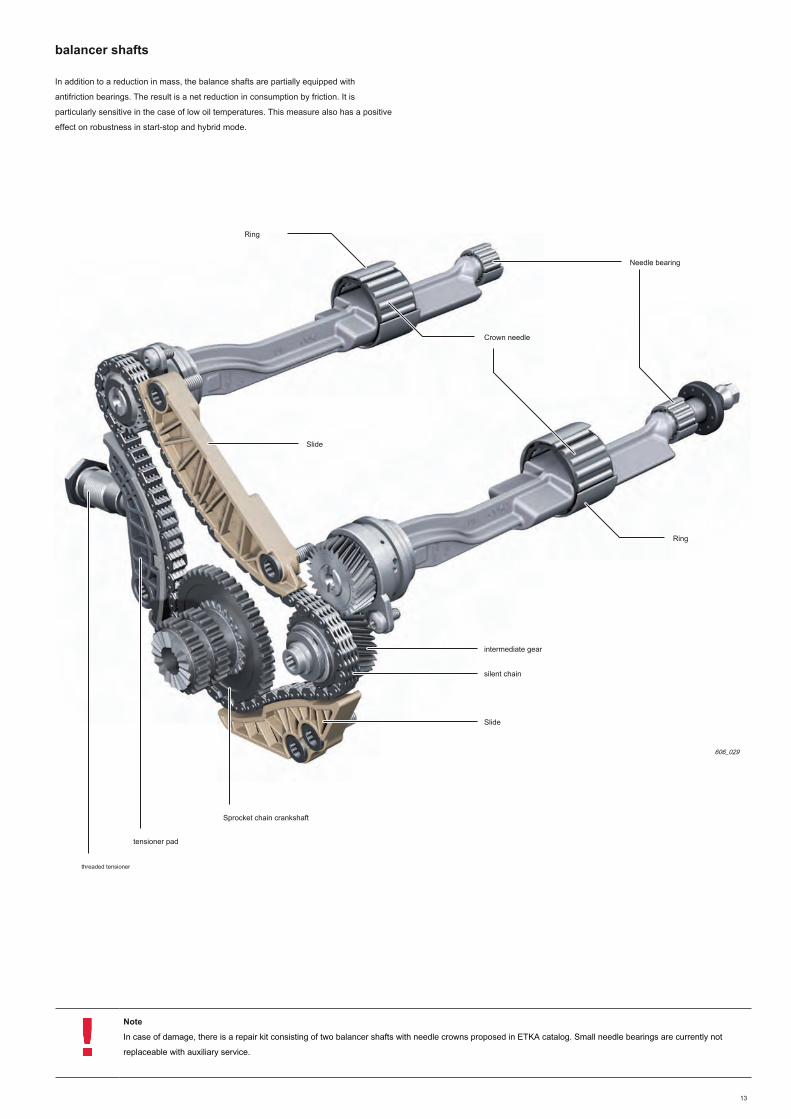
balancer shafts
In addition to a reduction in mass, the balance shafts are partially equipped with
antifriction bearings. The result is a net reduction in consumption by friction. It is
particularly sensitive in the case of low oil temperatures. This measure also has a positive
effect on robustness in start-stop and hybrid mode.
606_029
Slide
Slide
Ring
Crown needle
tensioner pad
threaded tensioner
Sprocket chain crankshaft
intermediate gear
silent chain
Needle bearing
Ring
Note
In case of damage, there is a repair kit consisting of two balancer shafts with needle crowns proposed in ETKA catalog. Small needle bearings are currently not
replaceable with auxiliary service.
14
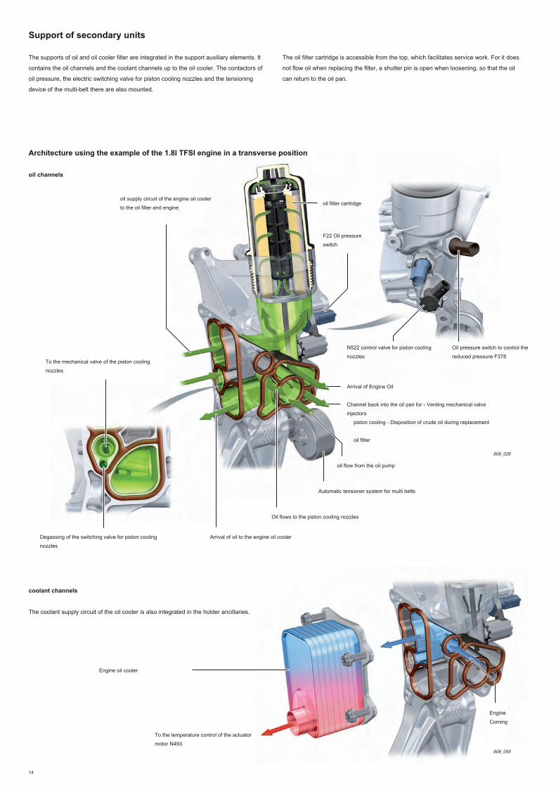
Support of secondary units
606_026
Architecture using the example of the 1.8l TFSI engine in a transverse position
606_055
oil channels
coolant channels
The oil filter cartridge is accessible from the top, which facilitates service work. For it does
not flow oil when replacing the filter, a shutter pin is open when loosening, so that the oil
can return to the oil pan.
The supports of oil and oil cooler filter are integrated in the support auxiliary elements. It
contains the oil channels and the coolant channels up to the oil cooler. The contactors of
oil pressure, the electric switching valve for piston cooling nozzles and the tensioning
device of the multi-belt there are also mounted.
The coolant supply circuit of the oil cooler is also integrated in the holder ancillaries.
To the temperature control of the actuator
motor N493
Engine
Coming
F22 Oil pressure
switch
Oil pressure switch to control the
reduced pressure F378
N522 control valve for piston cooling
nozzles
Engine oil cooler
oil filter cartridge
oil supply circuit of the engine oil cooler
to the oil filter and engine
Arrival of Engine Oil
Channel back into the oil pan for - Venting mechanical valve
injectors
piston cooling - Disposition of crude oil during replacement
oil filter
oil flow from the oil pump
Oil flows to the piston cooling nozzles
To the mechanical valve of the piston cooling
nozzles
Arrival of oil to the engine oil cooler
Automatic tensioner system for multi belts
Degassing of the switching valve for piston cooling
nozzles

15
Cylinder head
The new engine component that is most amazing is the head. This is a completely new
development. Cooling of integrated exhaust gas in the cylinder head and an exhaust gas
recirculation (IAGK) are implemented for the first time on turbocharged engines.
606_006
Exhaust camshaft with Audi valvelift system
Tree timing variator cam
Admission
Tree timing variator
Exhaust camshaft
Tree variable valve timing cam
actuators 1-8 F366 - F373
Ignition Coils 1-4 with output stage N70 power, N127,
N291, N292
gas channels to
turbocharger
integrated cooling channels
return
You will find more information about how the tree variable valve timing cam in the self-study program 255 "Engines 4-cylinder in line 2.0 liter V6 and 3.0
l".

16
2
5
6
7
8
10
11
12
13
15
18
14 9
4 3
1
17
16
16
606_031
legend:
1 Transmitter Hall 3 G300
2 Cylinder head cover
3 Actuators 1-8 of shaft variable valve timing cam F366 - F373
4 Intake camshaft
5 Shaft drive intake cam
6 Roller rocker arm
7 support element
8 Valve admission according
9 Exhaust camshaft
10 Shaft drive exhaust camshaft10 Shaft drive exhaust camshaft
11 Exhaust valve
12 Transmitter Hall G40
13 Partitions sheet channel13 Partitions sheet channel
14 coolant temperature sender G62
15 Cylinder head15 Cylinder head
16 antifreeze plug16 antifreeze plug
17 Stud integrated exhaust manifold17 Stud integrated exhaust manifold
18 gasket
Architecture

17
Note
Some modifications were made to the assembly work at the head also. For example, it is necessary, when removing the cylinder head, before dismantling the
cylinder head cover. For accurate approach, see the relevant Workshop Manual.
Steel screws are used for screwing the cylinder head cover. Sealing to the cylinder
head cover is performed with a liquid sealant.
Weatherization
The sealing between the cylinder block and cylinder head is ensured by a three-layer
metal head gasket. control side, the sealing is provided by a plastic chain case cover.
The oil filler cap is now built.
Audi valvelift system (AVS)
The Audi valvelift system has been developed to optimize the renewal of gas. This
system was implemented for the first time on the 2.8L FSI V6 engine of the Audi A6 05
in late 2006.
To improve the torque characteristic, the proven Audi valvelift AVS system (switching
valves on two levels) was taken from the 2.0l TFSI engine of the 2nd generation
(predecessor engine) - 436 Self-Study program.
Another important innovation is the implementation of a shaft drive cam on the camshaft
exhaust. This helped to achieve maximum degrees of freedom to control the renewal of
gas. The AVS system and the drive of exhaust cam shaft timing can adapt the needs of
the renewal of the various gases in the full load range and partial load.
Other changes:
• of long spark plug thread
• New pencil coils
• camshafts optimized weight
• Roller rocker arms optimized (reducing friction)
• Decrease spring forces in the valve train
• New oil filler cap positioned in the upper chain guard
• coolant temperature sensor G62 positioned in the cylinder head (GTI)
• New position of the high pressure pump
• oil separator improved end
• The turbocharger turbine casing is screwed directly to the cylinder head
• Optimization of inlet channels
• Development of injection components including an acoustic decoupling
return
You can find more information on the functions of the Audi valvelift system in the self-study program 411 "FSI engines of 2.8 l and 3.2 l with Audi Audi valvelift
system."
Tree variable valve timing cam
The result is a faster establishment of the couple. Due to the high torque up to 320 Nm
in a broad band system, the gear box can be adapted differently (downspeeding). This
reduces fuel consumption.

18
The exhaust channel are positioned such that the flow of exhaust gas from the cylinder
occurs where the exhaust has no disturbing influence on the scanning of another
cylinder.
exhaust channels
integrated exhaust manifold (IAGK)
One of the main novelties is the exhaust manifold cooled with dissociation of the ignition
timing, which is now integrated directly into the cylinder head. Due to the implementation
of an integrated exhaust manifold is obtained, compared to a conventional collector, a
net reduction of the temperature of the exhaust upstream of the turbine. It is also used a
turbocharger resistant to high temperatures.
With this combination, it is possible, especially at high speeds, to give up a large part in
enrichment at full load in order to protect the turbine. Thus, consumption can be
significantly reduced in normal driving mode as in the case of a sporty drive. In addition,
the integrated exhaust manifold supports the rapid warming of the coolant and thus an
essential component of thermal management
606_007
gas channels to the
turbocharger
integrated exhaust manifold
turbocharger
The full energy of the flow is thus available for driving the turbocharger turbine. exhaust
gas channels of the rolls 1 and 4 and the cylinders 2 and 3 converge respectively at the
transition point to the turbocharger.

19
The integrated exhaust manifold supports the rapid warming of the coolant and thus
constitutes an essential element of thermal management.
Phase actuation, heat is induced at the end of a very short time in the cooling liquid. This
heat is used immediately for engine warm-up as well as heating the passenger
compartment. Because of the lower heat loss and short strokes, the downstream
components (Lambda sensor, turbocharger and catalyst) can more quickly reach their
operating temperature.
Cooling the integrated exhaust manifold
606_032
Channel exhaust gas turbocharger with flange
connection
upper coolant area
Coolant area less water main
shirt
inlet side
exhaust side
There passage cooling mode after a short actuation phase. This is necessary because
the coolant is quickly brought to boiling in the integrated exhaust manifold area. It is for
this reason that the coolant temperature sender G62 is mounted on the hottest place in
the cylinder head.
e-media
Animation for the cylinder head and the
integrated exhaust manifold.

20
606_043
Degassing of the housing and crankcase gases
synoptic
Valve failure of the oil return to the end of the oil
separator (below the oil level in the sump)
oil return channel from the coarse oil separator (below
the oil level in the sump)
crude oil separator
Canal oil return from the end of
the oil separator
Introduction of crankcase gases into the intake manifold module (in air mode)
Introduction of crankcase gases into the turbocharger (supercharger mode)
Module end oil separator
The crankcase ventilation system and crankcase gases has also been a systematic
development. The pressure ratio of the cylinder block and the ambient air is set to a
larger pressure difference. This has a positive impact on the engine's oil consumption.
More attention was also paid to the reduction of components. Thus, there are outside of
the motor more than a conduit for discharging the cleaned crankcase gases.
The system includes the following elements:
• crude oil separator in the cylinder block
• oil separator module end screwed into the cylinder head cover
• Pipe for discharging the cleaned crankcase gases
• Back of oil in the cylinder block with shut-off valve in the insert in the oil sump
of the honeycomb.
21
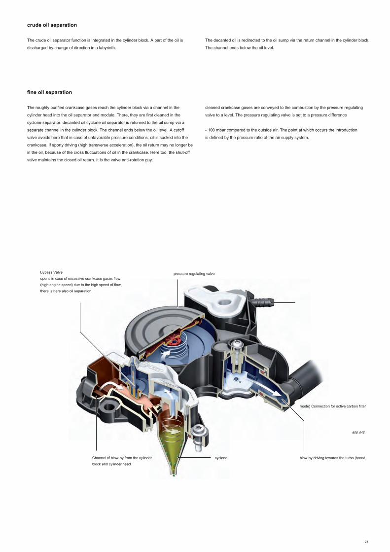
crude oil separation
The crude oil separator function is integrated in the cylinder block. A part of the oil is
discharged by change of direction in a labyrinth.
fine oil separation
The roughly purified crankcase gases reach the cylinder block via a channel in the
cylinder head into the oil separator end module. There, they are first cleaned in the
cyclone separator. decanted oil cyclone oil separator is returned to the oil sump via a
separate channel in the cylinder block. The channel ends below the oil level. A cutoff
valve avoids here that in case of unfavorable pressure conditions, oil is sucked into the
crankcase. If sporty driving (high transverse acceleration), the oil return may no longer be
in the oil, because of the cross fluctuations of oil in the crankcase. Here too, the shut-off
valve maintains the closed oil return. It is the valve anti-rotation guy.
606_045
cycloneChannel of blow-by from the cylinder
block and cylinder head
blow-by driving towards the turbo (boost
mode) Connection for active carbon filter
cleaned crankcase gases are conveyed to the combustion by the pressure regulating
valve to a level. The pressure regulating valve is set to a pressure difference
- 100 mbar compared to the outside air. The point at which occurs the introduction
is defined by the pressure ratio of the air supply system.
The decanted oil is redirected to the oil sump via the return channel in the cylinder block.
The channel ends below the oil level.
pressure regulating valve
Bypass Valve
opens in case of excessive crankcase gases flow
(high engine speed) due to the high speed of flow,
there is here also oil separation

22
Incorrect installation of detection
In some markets, such as North America, the legislation requires keying components
that affect the exhaust.
If the return line on the crankcase gas recycling module is not mounted or incorrectly
mounted, the incorrect installation of the sensor fitting is open.
As this connection is directly connected to the side air intake of the cylinder head, the
engine immediately draws in unmeasured disturbance air. It is detected by the lambda
control.
606_047
full charge (boost mode) Mode
blow-by driving towards the turbo (boost
mode)
cyclone
bypass valve
Conveying the cleaned crankcase gases to the combustion
After the fine separation and transfer by the pressure regulating valve, cleaned
crankcase gas is passed to combustion. The steering valve is automatically ensured by
the automatic check valves integrated in the oil separator end module.
The check valves come back to the basic position to stop the engine. The check valve in
the direction of the turbocharger is opened. The check valve in the direction of the intake
manifold is closed.
Check valve 1 (closed)2 check valve (open)
As pressure prevails throughout the charge air system, the check valve 1 closes.
Under the effect of the pressure difference between the internal pressure of the
crankcase and the intake side of the turbocharger, the check valve 2 is opened.
cleaned crankcase gases are sucked by the compressor.

23
A crankcase gas is via the vent line connected upstream of the turbine and a gauged hole
in the ventilation flap of the crankcase. The system is designed so that the aeration takes
place in atmospheric mode.
The crankcase gas, with oil separator and fine pressure control, mounted in a module
on couvreculasse.
Crankcase gases ( PCV *)Crankcase gases ( PCV *)
606_046
Slow and partial load lower range (air mode)
blow-by pipe towards the intake manifold (air
mode) Introduction of crankcase gases
Fitting the carbon filter pressure control
valve
Check valve 2 (closed)
calibrated bore crankcase
gases
PCV valve
In air mode, the check valve 1 in the intake manifold is opened and the check valve 2
closed under the effect of depression.
Check valve 1 (open)
PCV valve membrane
(dismounted)
606_083
cleaned crankcase gases are conveyed directly to the combustion via the intake
manifold.
blow-by pipe towards the intake manifold (air
mode)
Introduction of crankcase gases
cyclone

24
18
17
15
16
1
6
3
12 13 14
4
A
AT
2
TO 5
April
3
4
thirty
29
28
27
26
19
System overview
legend:
AT shaft bearing cam
B support element
C balance shaft bearing
D exhaust balancer shaft, bearing 1
E rod
F crankshaft bearings 1-5
1 1 solenoid valve variable valve in the exhaust N318
2 Hydraulic pallet inverter (exhaust)
3 Check valve, integrated into the bearing ramp
4 Oil strainer
5 1 solenoid valve variable valve N205
6 Drive hydraulic pallet (admission)
7 Check valve integrated in the cylinder head
8 oil separator end
9 Vacuum pump
10 strangulation10 strangulation
11 Lubricating the cam for high-pressure fuel pump
12 Oil Cooler12 Oil Cooler
13 Check valve, integrated into the oil filter13 Check valve, integrated into the oil filter
14 Oil Filter
15 oil drain valve15 oil drain valve
16 Oil pressure switch F22 (2.3 to 3.0 bar)16 Oil pressure switch F22 (2.3 to 3.0 bar)
17 Oil pressure switch for control 17 Oil pressure switch for control
F378 reduced pressure (0.5 to 0.8 bar)
18 control valve for injectors 18 control valve for injectors
piston cooling N522
19 mechanical switching valve19 mechanical switching valve
20 chain tensioner, balancing shafts
21 chain tensioner, chain drive
22 turbocharger
23 crude oil separator23 crude oil separator
24 Oil pressure switch, level 3 F44724 Oil pressure switch, level 3 F447
25 Lubricating gear stage25 Lubricating gear stage
26 level transmitter and G266 oil temperature
27 cold start injector
28 Check valve, built-in oil pump28 Check valve, built-in oil pump
29 Oil pump control29 Oil pump control
thirty Oil pressure regulating valve N428thirty Oil pressure regulating valve N428
Ramp bearings
Support of secondary
units
upper part of
the oil pan
high pressure circuit low
pressure circuit
Bottom of the oil pan
Oil supply

25
8
9
10
22
7
20
11
AT AT AT AT AT
AT AT AT AT
BB BB BB BB
BB BB BB BB
C C C
C C C
E E E E
F F F F F
4
4 April
21
24
25
23
D
606_018
Cylinder Block
Cylinder head
oil passages
Vacuum pump

26
Oil supply
Optimizations and systematic improvements have also been made at the pressurized oil
circuit. The main objectives were:
• Optimization of pressure channels in the oil circuit, hence reducing pressure
losses coupled with an increase in volume
• Reducing pressure losses in the oil pressure circuit
• Expansion of the rev range at low pressure
• Decrease the oil pressure level low pressure
• Switchable piston cooling nozzles
Overall, these measures have achieved a significant reduction in engine friction. It was
thus possible to achieve a further reduction of fuel consumption.
606_003
Changes to the oil pump:
• Pressure levels changed
• Increased yield
• Changes in hydraulic control of the piston cooling nozzle
regulated oil pump Support ancillaries
Oil Filter
Oil CoolerOil pressure switch, level 3 F447
Crude oil
refined oil
Switchable piston cooling nozzles
Oil pressure switch
F22 oil pressure switch to
control the reduced
pressure F378
Oil pressure regulating valve
N428
N522 control valve for
piston cooling nozzles

27
606_033
606_034
Oil pump control
Lid
drive shaft with drive pump gear
translation unit
output shaftregulating spring cold start
injector
Piston control
check valve
driven pump gear (movable axially)
Pressure spring of translation unit
Pump body
Manifold
Oil strainer
The basic function of the oil pump is derived from the pump motor of the 2nd
generation. There are the following differences:
• The hydraulic regulation within the pump has been perfected. The pump can then
proceed to more precise control.
• The gear driving the pump has been modified so that the pump now rotates
slower, i = 0.96.
return
You can find more information about the architecture and operation and to control oil pump in the self-study program 436 "Changes TFSI engine chain drive
4-cylinder".

28
Switchable piston cooling nozzles
A cooling plunger heads is not required in each operating situation.
A targeted cut of piston cooling nozzles allows a new fuel economy improvement.
Another reason for the removal of spring calibrated piston cooling nozzles is the oil level
in overall lower pressure.
606_019
Speed [r / min]
Torque [Nm]
Mapping of piston cooling nozzles
Cooling off piston (oil temperature> 50 ° C) The system of switchable piston
cooling nozzles contains the following components:
• oil channel additional pressure in the cylinder block
• New piston cooling nozzles without spring valves; there are injectors of two different
internal diameters (injectors TFSI engines 1,8l have the smallest diameter)
• Oil pressure switch, level 3 F447 (closes at 0.3 to 0.6 bar)
• N522 control valve for piston cooling nozzles
• mechanical switching valve
piston cooling the injectors are activated as needed. This is calculated in a special
mapping in the engine control unit.
piston cooling injectors can be activated at low or high pressure.
The lid is located in the chain cover. The cover is characterized by its opening and
closing-off as well as safe and tight sealing water from the engine compartment relative
to the environment.
Compared to the old building, a functional separation occurs between the seal and the
bayonet. The sealing surface of the elastomer seal is rectangular smaller. In addition,
there is no relative movement of the seal relative to the cover of the housing when
mounting the cover on the engine. With the new construction, the actuation forces were
reduced to a minimum. The bayonet positions undetachably cover all 90 °.
oil filler cap
606_082
top of the oil filler cap with bayonet
Spring
rectangular seal
Bottom of the oil filler cap
The main factors of the calculation are:
• Engine load
• Engine speed
• Temperature calculated oil
Cooling the deactivated piston (oil temperature <50 ° C)

29
606_004
disabled piston cooling nozzles
Oil pressure switch to control the reduced pressure F378
606_005
activated piston cooling nozzles
mechanical switching valve closes the channel
towards the oil gallery piston cooling nozzles
control valve for piston cooling nozzles N522
currentless
mechanical switching valve, opens the channel in the direction of
the oil gallery piston cooling nozzles
control valve for piston cooling nozzles N522 with
current
the switching valve vent hose
The control valve for piston cooling N522 injectors is supplied with power by the engine
control unit. The control valve for piston cooling N522 injectors is then supplied with
power by the terminal 87. The engine control unit provides the grounding and hence the
closure of the electrical circuit.
N522 the valve and releases the control channel of the mechanical switching valve. The
oil under pressure is now applied to the control piston of the mechanical switching valve
from both sides. The spring pushes the mechanical switching valve and thus closes the
channel going to the oil gallery of the piston cooling nozzles.
Gallery to oil cooling piston injectors
disabled
control channel
The circuiting of the piston cooling nozzles is carried out by keeping N522 off. The control
channel to the mechanical switching valve then closes. As the oil pressure acts only on
one side of the switching valve, it moves and opens the channel to the oil gallery of the
piston cooling nozzles. The spring in the switching valve is then prestressed. The spring
force in the switching valve allows the opening of the oil gallery in the direction of the
piston cooling nozzles from an oil pressure of 0.9 bar. So that the switching valve comes,
after switching off the control valve for piston cooling nozzles N522 without delay in the
initial position, the oil must s' quickly flow from the control piston. For this there are a
separate channel, which ensures the flow of oil without pressure in the engine oil sump.
This is the same channel in which flows the oil when replacing the oil filter.
Needle oil filter
shutter
Oil Gallery to the active piston cooling
nozzles
Monitoring the function
When the piston cooling nozzles are activated, the contact in the oil pressure switch,
level 3 F447, closes. The switch is at the end of the oil gallery for piston cooling nozzles
(see page 26, figure 606_003).
The oil pressure switch can detect the following defects:
• No oil pressure on the piston cooling nozzles despite request
• Faulty oil pressure switch
• oil pressure in spite of the deactivation of the piston cooling nozzles
The control valve for piston cooling nozzles, the following electrical faults can be
detected:
• cable cut, piston cooling nozzles always enabled
• Short circuit to ground; cooling off piston
• Short circuit to +; piston cooling always on
In case of faults causing the piston cooling does not occur, the following backup
reactions are triggered:
• torque limiting and speed by the engine control unit
• No level of low oil pressure in the control oil pump
• There in the instrument cluster display a message that the plan is limited to 4000
rev / min, a beep, EPC warning light

thirty
Note
For specific connection diagrams to the vehicle, consult the relevant Repair Manual.
The cooling system is adapted to the vehicle equipment, as well as its engine.
We took here for example the TFSI version 1.8l longitudinal position with manual
transmission and without stationary heating.
System overview
Circulation of the cooling liquid
606_009
rotary slide 1
8
rotary slide 2
8
Fitting box heating
Connections from and going to the heating heat
exchanger
1
circulation pump V50 Coolant
4
Channel integrated exhaust
manifold
turbocharger
9
Coolant radiator
15
Engine oil cooler
11
coolant expansion tank
6
It is thus the difference between longitudinal and transverse mounting, engine,
gearbox version and if the vehicle is equipped with a stationary heating.
The identification of the chart also includes the numbers of the legend on page 31.
Cooling system

31
1 2
3 4
5
1312
11109
8
7
6
15
14
1.8l TFSI engine longitudinally mounted, with manual transmission and without stationary heating
606_023
Liquid cooled cooling
Heated liquid cooling
ATF
legend:
1 Heat exchanger of the heating
2 Radiator transmission oil
3 Coolant shutoff valve N422 of the Climatronic
4 circulation pump V50 Coolant
5 coolant valve for box N488 speeds
6 coolant expansion tank
7 coolant temperature sender G62
8 coolant pump with engine temperature control actuator N493 (rotary valve 1 and 2)
9 turbocharger
10 integrated exhaust manifold (IAGK)
11 Engine oil cooler
12 Radiator fan V7
13 radiator fan V177 2
14 coolant temperature transmitter radiator outlet G83
15 Coolant radiator

32
606_035
Innovative Thermal Management (ITM)
During engine development, the complete coolant circuit has been revamped. The rapid
heating of the engine, a reduction in consumption as well as regulating the temperature
of the rapid and optimal engine thermodynamically and, if necessary, the heating
systems were the main targets.
The two main essential components of the innovative thermal management are integrated
exhaust manifold into the cylinder head (see section A cylinder head) and described
below, the N493 engine temperature control actuator. It is mounted as a module with the
coolant pump, the cold side of the engine.
Module of rotary and coolant pump
Back heating, turbocharger and gearboxrotary slide 1
Back radiator
Supply to radiator
rotary slide 2
toothed belt coolant pump
Pignon coolant pump driveLid
Pinion toothed belt drive
coolant pump
606_040
85 ° C 90 °
C 95 ° C
100 ° C
105 ° C
legend:
Speed [r / min]
Torque [Nm]
Temperature of the cooling liquid at room temperature of 20 ° C.

33
2 5
6
7
8
10 September
11
1 April 3
engine temperature control actuator N493 (rotary valve)
The N493 engine temperature control actuator is identical to the engines of 1.8 l and 2.0
l, longitudinal position as cross. It regulates the coolant flow via two rotary slide valves
mechanically coupled. Regulation of the angular position of the rotary slide valve takes
place according to the instructions of different maps in the engine control unit.
By corresponding positioning of the rotary valve, it is possible to realize different switching
positions. This enables rapid heating of the engine, which results in a reduction in friction
and hence the fuel consumption. Furthermore, engine temperatures varying between 85 °
C and 107 ° C are achievable.
606_036
legend:
1 Training the N493 motor temperature control actuator with sensor
2 Nozzle for supply to radiator
3 Nozzle connection to the engine oil cooler
4 intermediate gear
5 rotary slide 2
6 rotary valve shaft 1
7 Rotary slide housing
8 Thermostat wax capsule (thermostat FS)
9 Stacking joints
10 Nozzle for return of the radiator10 Nozzle for return of the radiator
11 rotary slide 1

34
Depending on the temperature control of the actuator motor N493
A DC electric motor drives the rotary slide valve. The engine management is ensured via
the engine control unit by a PWM signal (12 V). The drive frequency is 1000 Hz.
The control signal is new. This is a digital signal, whose architecture is similar to a CAN
signal. The control takes place until the position determined by the engine control unit is
reached. A positive control (measured value in the vehicle diagnostic tester) means that
the rotary slide moves toward the opening.
The electric motor drives the rotary slide 1 by means of a worm gear screw sharp
reduction. It controls the coolant flow of the oil cooler, the cylinder head and the main
water heater. (The oil cooler box, the turbocharger and the return of heating are not
regulated.)
The rotary valve 2 is connected via a toothed spindles to the rotatable tray 1. The toothing
is designed so that the rotary slide valve 2 is coupled and decoupled in different angular
positions of the rotary valve 1. The rotary movement of the rotary valve 2 (opening of
coolant flow through the cylinder block) begins at a rotational angle position of the rotary
valve 1 of approx. 145 °. In a rotational angle position of the rotary valve 1 of approx. 85
°, there is again decoupling. Here, the rotary valve 2 has reached its maximum rotational
movement and fully open the coolant circuit of the cylinder block. The movements of
rotary slide valves are limited by mechanical stops.
Over the engine warms, the greater the rotary valve is rotated. Different rates are then
opened in the variable area.
For detecting the exact position of the rotary and recognize malfunctions, a rotational
angle sensor is mounted on the control board of the rotary valve. It delivers a digital
voltage signal ( SENT *) the engine control unit. The position of the rotary valve 1 can be voltage signal ( SENT *) the engine control unit. The position of the rotary valve 1 can be voltage signal ( SENT *) the engine control unit. The position of the rotary valve 1 can be
read in the measured values with the vehicle diagnostic tester.
606_010
Gear worm
rotary slide 1 Belt drive
coolant pump
rotary slide 2
temperature control of the actuator
motor N493
Back of the oil cooler
engine inletengine output
Supply to radiator
Back heating, turbocharger and gearbox
Back radiator

35
control strategy
The present description relates to the operation of the entire cooling liquid circuit during
the engine warm-up phase. The description for the engines of the Audi A4 12.
Warming
For the engine actuation, the rotary slide 1 is moved into position 160 °. In this position,
the connections of the engine oil cooler and the main water radiator return are closed
on the rotary slide 1.
The rotary slide valve 2 closes the connection from the cylinder block. Coolant cutoff
valve climatronic N422 and the coolant valve for N488 gearbox are, at first, closed. The
recirculation pump coolant V51 is not driven. The circulation of the coolant through the
cylinder block is thus not possible. coolant stagnation is performed, depending on the
load and speed, until a maximum temperature of 90 ° C.
independent heating
In case of heating application, the coolant shutoff valve climatronic N422 and V51 coolant
recirculation pump are activated. The coolant flow then passes through the cylinder head,
the turbocompressor and heat exchanger of the heating.
Mini volume flow
This function serves to protect against overheating of the cylinder head (integrated
exhaust manifold) and the turbocharger, when the stagnation of coolant is formed in the
cylinder block. For this, the rotary disc 1 is brought into a position of approx. 145 °. From
this position, the teeth in time enters the rotary slide 2 and begins to open. A small
portion of the coolant is now discharged from the cylinder block in the cylinder head,
passes through the turbocharger and is returned through the module of rotary valve to
the coolant pump.
The second partial flow flows, if necessary, via the coolant shutoff valve N82 in the
direction of the heat exchanger of the heating. The recirculation pump coolant V51 is then
driven in case of "heat demand". The engine friction during actuation can be further
reduced through the rapid warming of the coolant.
606_062
606_063
606_064
36
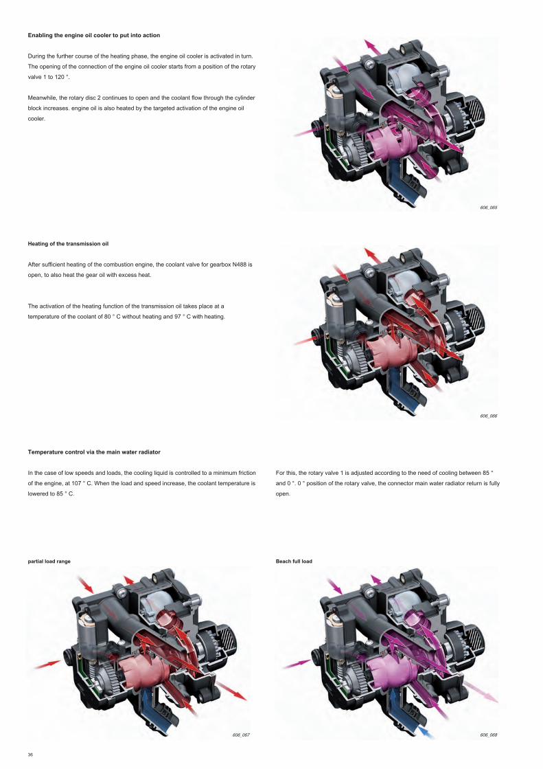
Enabling the engine oil cooler to put into action
During the further course of the heating phase, the engine oil cooler is activated in turn.
The opening of the connection of the engine oil cooler starts from a position of the rotary
valve 1 to 120 °.
Meanwhile, the rotary disc 2 continues to open and the coolant flow through the cylinder
block increases. engine oil is also heated by the targeted activation of the engine oil
cooler.
Heating of the transmission oil
After sufficient heating of the combustion engine, the coolant valve for gearbox N488 is
open, to also heat the gear oil with excess heat.
The activation of the heating function of the transmission oil takes place at a
temperature of the coolant of 80 ° C without heating and 97 ° C with heating.
Temperature control via the main water radiator
In the case of low speeds and loads, the cooling liquid is controlled to a minimum friction
of the engine, at 107 ° C. When the load and speed increase, the coolant temperature is
lowered to 85 ° C.
For this, the rotary valve 1 is adjusted according to the need of cooling between 85 °
and 0 °. 0 ° position of the rotary valve, the connector main water radiator return is fully
open.
partial load range Beach full load
606_065
606_066
606_068606_067

37
recirculation function after engine shutdown
To prevent boiling coolant in the cylinder head and turbocharger after the engine failure or
to avoid unnecessary cooling of the engine, the recirculation function is started on
demand mapping. It is activated for 15 minutes maximum after switching off the engine.
For this, the rotary slide valve is brought into "position recirculation" (160-255 °).
Regulating the coolant temperature was also performed in the recirculation. In the case of
an application for maximum recirculation (255 °) and a corresponding low temperature
coolant, the coupling main water radiator return is open, the connection from the cylinder
block being closed however via rotary slide 2. In addition,
The coolant then flows into two partial flows. On the one hand via the cylinder head to
V51, the second partial stream flows through the turbocharger via the rotary slide, and
then via the main water heater to return to the recirculation pump of the V51 engine
coolant.
In recirculation position, the crankcase is not crossed. This function has significantly
reduced the time of the recirculation function without generating excessive heat loss.
Default
606_077
In case of failure of the rotation angle sensor, the rotary slide valve is fully controlled
(maximum cooling of the engine). If the DC motor is defective, if the rotary valve is
jammed, a limitation on the speed and torque is enabled depending on the position of the
rotary valve.
Other reactions:
• There in the instrument cluster display a message that the plan is limited to 4000
rev / min, a beep, EPC warning light
• Display of the actual temperature of the coolant in the instrument cluster
• Opening of the coolant shutoff valve N82
• Activation of the recirculation pump V51 coolant to ensure the cooling of the
cylinder head.
If the temperature in the rotary valve exceeds 113 ° C, a wax capsule thermostat opens in
the rotary valve by-pass towards the main water heater, so that the coolant can flow
through the radiator main water (see page 33, figure 606_036). This will continue the trip
in case of default.
e-media
Animation on the innovative thermal management and
operation of the rotary valve.

38
3
1
2 4 5
coolant valve for box N488 speeds
The coolant valve for pilot gearbox arrivals hot coolant flow to the radiator transmission
oil. It is for example mounted on the Audi A5 12 with manual gearbox. The solenoid valve
is driven when required by the engine control unit with the on-board voltage. If it is not
controlled, it is open by mechanical force of the spring.
606_021
606_022
When starting the engine, it is closed. The coolant flows to the box is open at a
temperature of the coolant of 80 ° C and closed at 90 ° C. This assists the mechanical box
to reach its optimum temperature in terms of friction.
coolant flow to the radiator ATF
coolant flow to the engine
Piston
Electrical magnetic coil
Block diagram of the temperature control actuator motor N493
Connectors on the control actuator of the N493 engine temperature:
Sensor - (mass connection of the sensor, engine wiring)
Sensor signal
Sensor + (5 V in fitting the motor wiring)
actuator -
Actuator + 1
2
3
4
5

39
This pump is used on vehicles with engines in longitudinal position, recirculation pump for
the heat exchanger heating. It is controlled by the computer Climatronic J255 via a PWM
signal. It is diagnosable via the calculator Climatronic J255.
circulation pump V50 Coolant
Operation
When the recirculating pump V50 coolant running, the coolant is sucked via the flexible
engine coolant through the heat exchanger of the cooling block and the cooling liquid
shutoff valve and forwarded to the motor via the coolant hose.
The circulation pump V50 Coolant is with the ignition set, controlled depending on the
temperature of the coolant and the setting on the control unit and the air conditioner
display.
The vehicle equipment version is selected in coding and adaptation (eg. Stationary
mounted heating).
Coolant shutoff valve N422 of the Climatronic
Coolant cutoff valve is mounted on the engine in the longitudinal position and without
stationary heating.
It is identical to the coolant valve for the gearbox N488 (see page 38).
If it is not controlled, it is open (the coolant flows). When driving, it is closed. The
opening is provided by the mechanical force of the spring.
Operation
After engine startup, it is closed. It is open if desired heating, cooling and recirculating
start-stop demand.
The steering "black and white" is provided by the computer Climatronic J255.
N422 Climatronic coolant shut-off valve must be properly adjusted in the computer.
The pump is mounted on vehicles with engine in a transverse position. It is identical to
the V50 pump fitted to engines in longitudinal position. The control of the engine
control unit is provided by the computer by means of a PWM signal. The pump
recirculation V51 coolant is controlled by the engine control unit on request of the
control unit (ECU heating J65) or Climatronic J255 calculator.
The cutoff valve N82 coolant is controlled by the engine control unit.
It is among others mounted on the Audi A3 with 13 stationary heating.
recirculating pump V51 Coolant
cutoff valve N82 coolant
It cuts in the case of a cold engine, depending on the setting on the control unit (ECU
heating J65) or Climatronic J255 calculator coolant flow through the heat exchanger of
the heating, ex. to speed up the engine warm.
It is also responsible for the assistance of the pump engine coolant to improve cooling
fluid flow rate through the heat exchanger of the heating at given engine speeds, with a
view to improving the power heating.
In addition, the temperature in the turbocharger can be reduced more rapidly. This
improves the lifetime of the engine oil.
606_056
return
You will find more information on the operation of the recirculation pump coolant V50 / V51 in the self-study program 616 "1.2l TFSI and 1.4l engines of the Audi
EA211 line."
The valve opens and closes the coolant flows from the heat exchanger of the vehicle
heating, cf. page 31, figure 606_023.
circulation pump V50 Coolant

40
E
C
B
N316
G336
N249
F
J338
G186
G187
G188
V465
AT D
G
G31
606_025
legend:
AT Flow of exhaust gas
B turbocharger
C Air filter
D flow of fresh air
E wastegate flap
F charge air radiator
G Intake manifold flaps
Exhaust gas
Air intake (depression) air intercooler
(boost pressure) Recirculation
deceleration (boost pressure)
G31 Boost pressure transmitterG31 Boost pressure transmitter
G42 Intake air temperature senderG42 Intake air temperature sender
G71 intake manifold pressure transmitterG71 intake manifold pressure transmitter
G186 throttle drive G186 throttle drive
(Electric throttle control)
G187 angle transmitter 1 of the throttle drive G187 angle transmitter 1 of the throttle drive
(Electric throttle control)
G188 Angle transmitter 2 of the throttle drive G188 Angle transmitter 2 of the throttle drive
(Electric throttle control)
G336 Potentiometer intake manifold flapG336 Potentiometer intake manifold flap
J338 throttle control unitJ338 throttle control unit
N249 air recirculation valve TurbochargerN249 air recirculation valve Turbocharger
N316 intake manifold flap valveN316 intake manifold flap valve
V465 Boost pressure actuatorV465 Boost pressure actuator
Note
The V465 boost pressure actuator must be replaced after loosening the nuts against the rod. After replacement, the boost pressure actuator must be adjusted
with the vehicle diagnostic tester.
G42 G71
System overview
air and boost supply

41
air guide on the motor in a transverse position
606_037
turbocharger
(B)
charge air radiator
(F)
Air filter
(C)
throttle control unit J338
Manifold
intake
(D)
Intake air temperature sender G42 with intake manifold pressure sender G71
Boost pressure transmitter G31
Intake manifold flap valve N316
V465 boost pressure actuatorair recirculation valve N249
Turbocharger
Intake manifold flap
potentiometer G336

42
air guide on the motor in the longitudinal position
606_038
turbocharger
charge air radiator
Air filter
throttle control unit J338
Manifold
intake
Intake air temperature sender G42 with
intake manifold pressure sender G71
Boost pressure
transmitter G31
Intake manifold flap valve N316V465 boost pressure actuator
Intake manifold flap
potentiometer G336

43
Manifold
Because higher boost pressures, the integrated intake manifold flap system in the intake
manifold has been completely overhauled. The stainless steel shaft in a portion, angled,
ensures a resistance to the maximum torque for the trough-shaped flaps in the intake
channel. Detecting the positioning of the flaps is ensured by the intake manifold flap
potentiometer G336 (rotation angle sensor without contact).
606_041
606_042
Intake manifold flaps
Intake air temperature sender G42 with intake
manifold pressure sender G71
trough the flaps are in the open state, biased in the base body, so as to minimize the
excitations by the air flow. The shaft is switched electropneumatically with a capsule
controlled by depression (two-position control) by the computer via the N316 intake
manifold flap valve.
Intake manifold flap potentiometer
G336
Intake manifold flap valve N316
depression capsule of swirl flaps
high pressure pump
N290 fuel metering valve
FSI injectors
throttle control unit J338
FSI injectors
MPI injectors
44
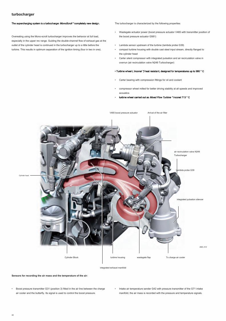
The supercharging system is a turbocharger MonoScroll * completely new design. The supercharging system is a turbocharger MonoScroll * completely new design. The supercharging system is a turbocharger MonoScroll * completely new design.
Overeating using the Mono-scroll turbocharger improves the behavior at full load,
especially in the upper rev range. Guiding the double-channel flow of exhaust gas at the
outlet of the cylinder head is continued in the turbocharger up to a little before the
turbine. This results in optimum separation of the ignition timing (four in two in one).
The turbocharger is characterized by the following properties:
• Wastegate actuator power (boost pressure actuator V465 with transmitter position of
the boost pressure actuator G581)
• Lambda sensor upstream of the turbine (lambda probe G39)
• compact turbine housing with double cast steel input stream, directly flanged to
the cylinder head
• Carter silent compressor with integrated pulsation and air recirculation valve in
overrun (air recirculation valve N249 Turbocharger)
• Turbine wheel ( Inconel *) heat resistant, designed for temperatures up to 980 ° C• Turbine wheel ( Inconel *) heat resistant, designed for temperatures up to 980 ° C• Turbine wheel ( Inconel *) heat resistant, designed for temperatures up to 980 ° C
• Carter bearing with compression fittings for oil and coolant
• compressor wheel milled for better driving stability at all speeds and improved
acoustics
• turbine wheel carried out as Mixed Flow Turbine * Inconel 713 ° Cturbine wheel carried out as Mixed Flow Turbine * Inconel 713 ° Cturbine wheel carried out as Mixed Flow Turbine * Inconel 713 ° C
Sensors for recording the air mass and the temperature of the air:
• Boost pressure transmitter G31 (position 3) fitted in the air line between the charge
air cooler and the butterfly. Its signal is used to control the boost pressure.
606_013
V465 boost pressure actuator
air recirculation valve N249
Turbocharger
integrated pulsation silencer
Lambda probe G39
wastegate flapturbine housing
turbocharger
• Intake air temperature sender G42 with pressure transmitter of the G71 intake
manifold, the air mass is recorded with the pressure and temperature signals.
To charge air cooler
Arrival of the air filter
Cylinder Block
Cylinder head
integrated exhaust manifold

45
V465 boost pressure actuator
An electric wastegate actuator is implemented for the first time on an engine
supercharged four-cylinder Audi. This technology offers the following advantages
over vacuum capsules used previously:
• faster and more accurate response
• Can be controlled independently of the applied boost pressure
• Because of the higher closing force, the maximum torque of 320 Nm engine is
reached at a low engine speed of 1500 rev / min.
• The base boost pressure can be lowered with an active opening of the part-load
wastegate This allows approx fuel economy. 1.2 g CO 2 / km in the MVEG cycle.wastegate This allows approx fuel economy. 1.2 g CO 2 / km in the MVEG cycle.wastegate This allows approx fuel economy. 1.2 g CO 2 / km in the MVEG cycle.
• Due to the active aperture of the wastegate during heating of the catalyst, there is
obtained an increased temperature of the exhaust gas of 10 ° C upstream of the
catalyst, leading to lower cold-start emissions.
• Due to the high operating speed of the actuator of the wastegate, immediate
elimination of boost pressure when negative stress cycles (deceleration) is possible,
which has a positive impact, particularly in behavior acoustic turbocharger (whistle
blowing).
606_079
V465 boost pressure actuator Transmitter position of the supercharge pressure
actuator G581
wastegate actuating lever with clearance compensation elements and tolerance
on the push bar
Transmission
Fitting the engine control unit
Game compensation spring
spring plates
magnet holder

46
3
1 2 4 5 6
Full positioning mechanism consists of the following:
• Housing
• DC motor (boost pressure actuator V465)
• Transmission
Components of the supercharging pressure of the actuator system
The boost pressure actuator G581 position transmitter is mounted in the housing cover
of the transmission of the boost pressure actuator. In the housing cover there is also a
magnet holder with two permanent magnets. The magnet holder is engaged in the
housing cover and is based on the transmission spring plate. It therefore carries the
same movement as the push bar. When the push rod moves, the magnets are moved
along the Hall sensor, which is also located in the housing cover, and the actual value of
the displacement path is recorded. The movement path is supplied as a linear analog
voltage signal.
Functional scheme
606_020
Operation
The DC motor moves the wastegate flap via the transmission unit and the thrust rod. The
limitation of the movement is performed in the case of the mechanical stop by the bottom
external abutment wastegate flap in its seat and, in the case of the upper mechanical
stop, by the inner boundary of the transmission on the housing.
Connections on the boost pressure transmitter V465:
• integrated position sensor without contact (position transmitter to boost pressure
actuator G581)
• upper and lower mechanical stops transmission
• Game compensation elements and tolerance on the push bar
Transmitter position of the supercharge pressure actuator G581
The DC motor drive frequency takes place in a frequency range of 1000 Hz via the
engine control unit. The length of the push bar is adjustable. A setting wastgate flap is
possible after replacement of the actuator.
Sensor + (5 V in fitting the motor wiring)
actuator -
Mass
not occupied
Sensor signal
Actuator + 1
2
3
4
5
6

47
The compressor casing has been enhanced due to the high actuation forces of the V465
boost pressure actuator. It is made of cast aluminum. Furthermore the compressor wheel,
the muffler pulsation, the air recirculation valve N249 turbocharger and the introduction
point for the gas from the degassing of the crankcase and the reservoir are integrated. To
meet the temperature requirements of the higher exhaust gas of the order of 980 ° C and
the provision of the lambda probe upstream of the turbine in the housing, the turbine
housing is formed, unlike the second generation, in a new cast aluminum material in the
housing configuration. To achieve optimal separation of the ignition sequence,
As the turbine casing has very compact dimensions, the concept of screwing with the
bolt used is a standard screw-bolt and nut. The turbine wheel is designed as Mixed Flow
turbine (semi-radial turbine).
Turbine housing and turbine wheel
606_080
V465 boost pressure actuator
air recirculation valve N249
Turbocharger
integrated pulsation
silencer
lambda probe G39
wastegate flap
turbine housing
Turbine
compressor wheel
The lambda sensor (upstream of the catalyst) is positioned at a strategic point where the
exhaust gases of each cylinder are pushed to the turbine housing, and temperatures are
still not too high.
The lambda probe G39 is a lambda probe LSU 4.2 broadband.
Flange to head
This allows a much earlier end of the dew point and thus a rapid validation of the
lambda control (six seconds) after engine start and a good detection of the individual
cylinders.
The compressor wheel is countersunk in one portion. This allows for better driving stability
at all speeds and improved acoustics.
compressor casing and compressor wheel
lambda probe G39

48
System overview
606_017
Injectors for cylinders 1-4 N30 - N33
injectors for cylinders 2 1-4 N532 - N535
fuel pump (frontloading
pump) G6
fuel pump calculator J538Battery
(positive)
To engine control unit
Fuel Filter
Mass
G247 Fuel Pressure
Transmitter
High fuel pressure ramp
high pressure fuel pump
low fuel pressure ramp
Fuel pressure sender, low pressure G410
N290 fuel metering valve
fuel supply system

49
Critics increasingly frequent at gasoline engines with direct injection, whereby rejection of
very fine soot particles is almost ten times higher than existing diesel engines has led to
the development of dual injection system.
Packaging mixing / dual injection system
The following objectives were achieved:
• Raising the system pressure of 150 to 200 bar.
• Improved acoustics
• Achievement of limit values for Euro6 mass and amount of particles (net
reduction of soot emissions, factor 10)
• Reducing emissions, including CO 2Reducing emissions, including CO 2
satisfaction and compliance with current and future emission standards
• Adoption of an injection system for additional intake manifold
• Reduction in partial load consumption, the advantage held by the use of injection
MPI
MPI injection system
high pressure injection system
The MPI system power is supplied via the scanning coupling of the high pressure
pump. The high pressure pump continues to be traversed automatically by the fuel
during the MPI mode and is cooled.
To reduce pulsation that the high pressure pump induced into the manifold, a
throttle is integrated in the scanning coupling of the high pressure pump.
For the system pressure up to 200 bar, all parts of the high pressure part have been
adapted. The injectors were acoustically decoupled from the cylinder head via elastic
steel washers. The high pressure common rail was also decoupled from the intake
manifold is screwed to the cylinder head. The position of the high-pressure injectors is
slightly recessed.
return
You will find more information on the concept of regulation of the high pressure injection system in Self-Study Programme 384 "engine TFSI 4-cylinder 1.8l
Audi chain drive."
606_012
high pressure fuel pump
Injectors for cylinders 1-4 N30 - N33
Butterfly
Fuel pressure sender, low pressure G410
Injectors for cylinders 2 1-4 N532 - N535
low fuel pressure ramp
High fuel pressure ramp
high pressure system
low pressure system
N290 fuel metering valve
The MPI system has its own pressure sensor, fuel pressure sender, low pressure
G410. The pressure supply as required is provided by the prefeed pump G6 in the fuel
tank. Frontloading G6 pump is controlled by the pump calculator J538 fuel via the
engine control unit. MPI ramp is made of plastic. MPI injectors (N532 - N535) are
mounted in the intake manifold in plastic and optimally arranged for guidance of the jet.
This helped to improve the homogenization of the mixture and reduce the thermal stress
of the valves. For the future a concept similar regulation for all engines, it has been
redesigned. The following rule of thumb applies to the concept of regulation: With the
profile of the pressure regulating valve N276 Fuel disconnected, there is no
establishment of pressure in the high pressure range.
Intake air temperature sender G42 with
intake manifold pressure sender G71
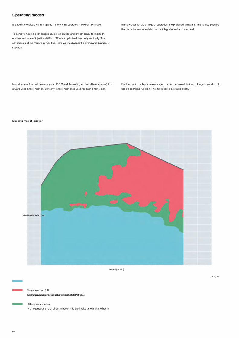
50
Operating modes
It is routinely calculated in mapping if the engine operates in MPI or ISP mode.
To achieve minimal soot emissions, low oil dilution and low tendency to knock, the
number and type of injection (MPI or ISPs) are optimized thermodynamically. The
conditioning of the mixture is modified. Here we must adapt the timing and duration of
injection.
In the widest possible range of operation, the preferred lambda 1. This is also possible
thanks to the implementation of the integrated exhaust manifold.
In cold engine (coolant below approx. 45 ° C and depending on the oil temperature) it is
always uses direct injection. Similarly, direct injection is used for each engine start.
606_061
Speed [r / min]
Couple geared motor * [ nm]Couple geared motor * [ nm]
Mapping type of injection
FSI injection Double
(Homogeneous strata, direct injection into the intake time and another in
the compression stroke) Single Injection MPI
Single injection FSI
(Homogeneous direct injection in the intake stroke)
For the fuel in the high-pressure injectors can not coked during prolonged operation, it is
used a scanning function. The ISP mode is activated briefly.
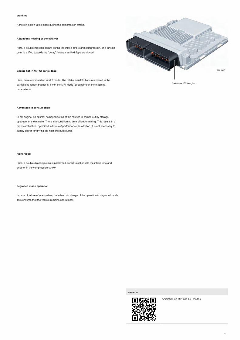
51
cranking
A triple injection takes place during the compression stroke.
Actuation / heating of the catalyst
Here, a double injection occurs during the intake stroke and compression. The ignition
point is shifted towards the "delay". intake manifold flaps are closed.
Engine hot (> 45 ° C) partial load
Here, there commutation in MPI mode. The intake manifold flaps are closed in the
partial load range, but not 1: 1 with the MPI mode (depending on the mapping
parameters).
Advantage in consumption
In hot engine, an optimal homogenisation of the mixture is carried out by storage
upstream of the mixture. There is a conditioning time of longer mixing. This results in a
rapid combustion, optimized in terms of performance. In addition, it is not necessary to
supply power for driving the high pressure pump.
higher load
Here, a double direct injection is performed. Direct injection into the intake time and
another in the compression stroke.
degraded mode operation
In case of failure of one system, the other is in charge of the operation in degraded mode.
This ensures that the vehicle remains operational.
606_089
Calculator J623 engine
e-media
Animation on MPI and ISP modes.

52
Synoptic TFSI engine system 1.8l CJEB (Audi A5 12)
sensors
Sensor 1 rattling G61
of the accelerator position sensor G79 transmitter 2 of throttle
position G185 clutch position transmitter G476 clutch pedal switch
F36Clutch pedal switch for engine start switch F194 F stop lights
Level Transmitter and oil temperature G266 engine speed sender G28
Boost pressure transmitter G31
pressure sensor brake booster G294
intake air temperature sender G42 Intake manifold pressure sender G71
Fuel pressure transmitter G247 Hall sender G40
Transmitter Hall 3 G300
coolant temperature sender G62
coolant temperature transmitter radiator outlet G83
lambda probe G39
lambda sensor downstream of the catalyst G130
Transmitter position of the supercharge pressure actuator G581
Additional signals: - Cruise control -
Speed signal
- Start request to the engine controller (Keyless Start 1 and 2) - Terminal 50
- Signal collision airbag computer throttle control unit J338
angle transmitters 1 + 2 of the throttle drive (electric throttle control) G187,
G188
Intake manifold flap potentiometer G336 Fuel pressure sender, low pressure
G410
fuel level indicator G Transmitter 2 Transmitter fuel level G169 Oil
pressure switch F22
Oil pressure switch to control the reduced pressure F378
Oil pressure switch, level 3 F447 G604 ratio detection
sensor
Calculator J623
engine
Engine management

53
actuators
606_076
oil pressure regulating valve N428 coolant valve for gearbox N488
circulation pump V50 Coolant
lambda probe heater Z19 heating Lambda probe 1 downstream of catalytic
converter Z29 air recirculation valve N249 Turbocharger Injectors for cylinders
2 1-4 N532 - N535
Solenoid 1 activated charcoal filter N80 butterfly Training (electric throttle control)
G186
Boost pressure actuator valve V465 Intake manifold flap N316
fuel pump calculator J538 Fuel pump (pre-feed pump) G6 1 Solenoid variable valve
N205 Solenoid 1 variable valve in the exhaust N318
Additional signals: - Calculator automatic gearbox / engine speed -
calculator ABS / clutch position - Air conditioner compressor - starter
Steering Coils 1-4 with output stage N70 power, N127, N291, N292
Actuators 1-8 of shaft variable valve timing cam F366 - F373
N522 control valve for piston cooling nozzles
Injectors for cylinders 1-4 N30-N33
Solenoid left electrohydraulic engine bearing N144 solenoid right electrohydraulic engine
bearing N145 engine temperature control actuator N493 fuel metering valve N290
radiator fan calculator J293 Radiator fan V7 Radiator Fan
2 V177

54
Differences between 1.8 l / 2.0 l and between longitudinal and transverse position
Depending on the engine (1.8 l and 2.0 l) and position, longitudinal or transverse, the
engines have differences in power classes, components and the combustion process.
These differences are presented in the following pages.
longitudinal position transverse position
Power Class 1 12 Audi A4, Audi A5 12
1.8 l
125 kilowatts, 320 Nm
Audi A3 13
1.8 l 132 kilowatts, 280 Nm
power class 2 Audi Q5 13
2.0 l
165 kilowatts, 350 Nm
power class 3 Audi A3 13
2,0 l 221 kilowatts, 380 Nm
Overview of power classes
longitudinal position transverse position
Power Class 1
power class 2
power class 3
Overview of different pieces
Differentiation Engine Versions

55
The following components have been adapted:
• upper part of the oil pan
• Insert honeycomb
• suction pipe of the oil pump
• oil pan
• turbocharger
Differences between the components longitudinal and transverse position
The components top and bottom of the oil pan, honeycomb insert and suction of the oil
pump has been modified to keep the same oil capacity (5.4 l) and answer the operating
criteria required of the oil circuit, such as oil pressure, oil foaming, transverse and
longitudinal dynamics, driving uphill and downhill.
turbocharger
oil pan
upper part of the oil pan
Insert honeycomb
suction pipe of the oil pump
Of 1.8 l TFSI engine in a transverse position
606_071
e-media
Animation on the differences between longitudinal and
transverse position, taking for example the TFSI engine
1,8l.
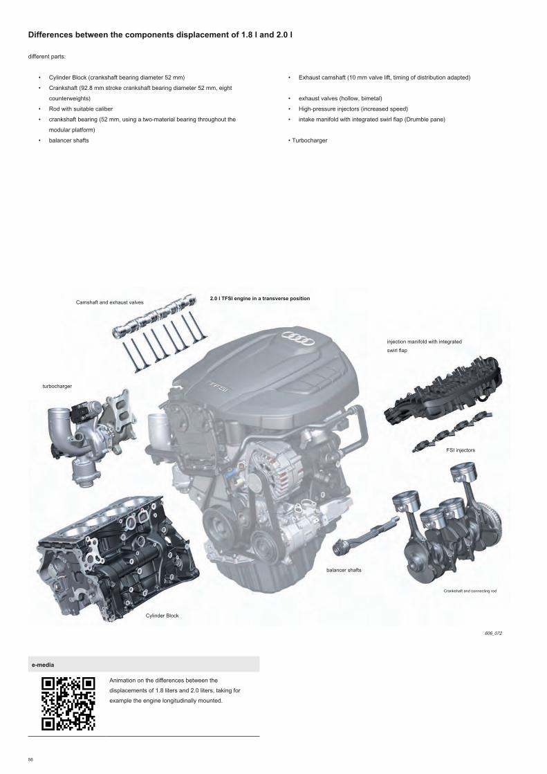
56
Differences between the components displacement of 1.8 l and 2.0 l
different parts:
• Cylinder Block (crankshaft bearing diameter 52 mm)
• Crankshaft (92.8 mm stroke crankshaft bearing diameter 52 mm, eight
counterweights)
• Rod with suitable caliber
• crankshaft bearing (52 mm, using a two-material bearing throughout the
modular platform)
• balancer shafts
• Exhaust camshaft (10 mm valve lift, timing of distribution adapted)
• exhaust valves (hollow, bimetal)
• High-pressure injectors (increased speed)
• intake manifold with integrated swirl flap (Drumble pane)
• Turbocharger
turbocharger
balancer shafts
Crankshaft and connecting rod
Cylinder Block
Camshaft and exhaust valves
2.0 l TFSI engine in a transverse position
606_072
FSI injectors
injection manifold with integrated
swirl flap
e-media
Animation on the differences between the
displacements of 1.8 liters and 2.0 liters, taking for
example the engine longitudinally mounted.

57
components on the Audi S3 13
The following components have been adapted:
• Cylinder head with another alloy than other engines of this group, due to the
higher thermal stress
• exhaust valves (hollow Ni content higher, nitrided)
• Rings exhaust valve seat (temperature resistance and improved wear)
• Exhaust camshaft (setting of the appropriate distribution)
• Compression ratio 9.3: 1
• piston cooling nozzles (increased speed)
turbocharger
piston cooling nozzles Piston Cylinder
camshaft and exhaust valve seat rings
2.0l TFSI engine from the Audi S3 13
606_073
FSI injectors
• High-pressure injectors (further increased speed)
• Turbocharger
• boost pressure up to 1.2 bar
• main water radiator high performance with 1 to 2 additional water heaters
(depending on national version)
• Additional acoustic measurements for a sporty sound with a sound actuator (for
the passenger) and components of exhaust gases in the exhaust system
e-media
Animation on the modified engine components
from the Audi S3 13.
e-media
Animation on the Audi S3 13.

58
1
2
3
4 3
2
1 1
2
3
2
1
4
3
2
1
AT
AT
BB
B
B
B
C
C
C
C
DD
D
EE
E
E
FF
F
F
F
G
G
Differences in turbochargers
One of the features of the turbocharger 13 is Audi S3 technology "abradeable seal"
(ICSI GmbH) in the compressor. A plastic insert is autorodant ensures a considerably
small gap between the impeller and the compressor casing. This increases the
compressor output level until additional 2%.
606_074
For the Audi S3 13 of the compressor wheel and even higher turbine are used and the
housing components have been adapted accordingly. To achieve high mass flow of
exhaust gas S3 13, is made use of more sophisticated materials for the turbine housing
as well as the turbine wheel.
606_078
legend:
air bypass valve during deceleration
Compressor housing
compressor wheel
bearings
Turbine
turbine housing
wastegate system
1.8 l MLB
2.0 l S3 13
2.0 l MLB
1.8 l MQB
AT
B
C
D
E
F
G
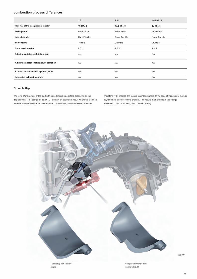
59
1.8 l 2.0 l 2.0 l S3 13
Flow rate of the high pressure injector 15 cm 3 / s 15 cm 3 / s 15 cm 3 / s 17.5 cm 3 / s 17.5 cm 3 / s 17.5 cm 3 / s 20 cm 3 / s20 cm 3 / s20 cm 3 / s
MPI injector same room same room same room
inlet channels Canal Tumble Canal Tumble Canal Tumble
flap system Tumble Drumble Drumble
Compression ratio 9.6: 1 9.6: 1 9.3: 1
A timing variator shaft intake cam Yes Yes Yes
A timing variator shaft exhaust camshaft Yes Yes Yes
Exhaust - Audi valvelift system (AVS) Yes Yes Yes
integrated exhaust manifold Yes Yes Yes
combustion process differences
Drumble flap
The level of movement of the load with closed intake pipe differs depending on the
displacement (1.8 l compared to 2.0 l). To obtain an equivalent result we should also use
different intake manifolds for different cars. To avoid this, it uses different swirl flaps.
606_075
Tumble flap with 1.8l TFSI
engine
Component Drumble TFSI
engine with 2.0 l
Therefore TFSI engines 2,0l feature Drumble shutters. In the case of this design, there is
asymmetrical closure Tumble channel. This results in an overlap of the charge
movement "Drall" (turbulent), and "Tumble" (drum).

60
T10133 / 16 A Removal Tool
T40243 lever
T10133 / 18 Sleeve
T40267 wedging tool
Dismantling of high-pressure injectors
Special tool T10133 / 16 A replaces the old removal tool T10133 / 16.
(Equipment Group: A1)
Dismantling of high pressure injectors (Equipment
Group: A1)
To set up the crankshaft tensioner (Equipment Group:
A1)
Lock the tensioner (Equipment
Group: A1)
606_051606_050
606_049606_048
T40274 extraction Hook
Removing the crankshaft attached ring (Equipment
Group: A1)
606_054
Service
Special tools / workshop facilities
T40270 Socket XZN 12
Removing and installing mechanical bearing assembly
(Equipment Group: A1)
606_052
Annex

61
T40290 adjustment template
wastegate flap fixation during adjustment work of the turbocharger boost pressure actuator.
(Equipment Group: A1)
606_081
maintenance using the example of the 1.8l TFSI engine in the Audi A5 12 (motor letters benchmark CJEB)
Note
The indications of Service news documentation always apply.
intermediary service intervals with LongLife
Service
max. 30,000 km / 2 years as the maintenance display engine oil specification VW
504 00
intermediary service interval without LongLife
Service
every 15 000 km / after 1 year (whichever comes first) engine oil specification VW 504
00 or 502 00
Changing the oil filter at each intermediate maintenance
drain capacity of the engine oil 4.7 liters (with filter)
Suction / discharge of engine oil Both are possible
Scale values of the electronic indicator controller oil
level (when removing the dipstick)
Set for the adjusting ring (upper scale value): 32 set for the range of oil level min. max. (Lower scale value): 0-27
Replacing the air filter 90 000 km / 6 years
Sparkplugs 90 000 km / 6 years
Fuel Filter for life
Distribution Chain for life
Tensioner system of the distribution chain for life
multitrack belt for life
System multitrack belt tensioner for life
toothed belt coolant pump for life
Fixing T40271
sprockets attachment (Equipment
Group: A1)
606_053

62
Glossary
downspeeding
generally referred to by "downspeeding" the reduction in engine speed by changing the
gear box total. A gear optimized propulsion eating plan allows for consumption
improvements comparable to those obtained by engine downsizing. Due to the level of
power and average pressure higher supercharged engines, it is possible to achieve an
operating point shift towards lower and higher loads regimes. This means that the motor
can operate in a more favorable mapping range for consumption. downspeeding
concepts are generally linked to a concept of downsizing, this combination is particularly
suitable for gasoline engines with direct injection and turbocharging.
indexed engine torque
indexed engine torque called torque than the combustion engine could deliver
if it were free of losses.
Inconel
Inconel is a trademark of the Special Metals Corporation, designating a series of alloys
corrosion-resistant nickel. They are mainly used for high temperature applications
Mixed Flow Turbine (semi-radial turbine)
A "Mixed Flow" turbine is an intermediate solution between radial and axial turbine
turbine. The radial turbine wheel is driven radially (inlet edge parallel to the axis of
rotation). It is therefore well suited for small flow rates, as in the case of the VL. The attack
of the axial turbine wheel has for its location in the axial direction (direction of 90 ° from
the inlet edge relative to the axis of rotation) and more suitable for high flow rates for large
engines for example.
Mixed Flow turbine exhibit oblique inlet edge. As there is added an axial rotor element,
ideal for high flow rates, it is also possible to use a smaller rotor. The advantage of the
best behavior in the radial turbine combined response to the advantage of the better
performance of the axial rotor element in the upper rev range.
DLC
Diamond like carbon, this is an amorphous carbon, resembling the diamond. These
layers are characterized by very high levels of hardness and very low dry friction
coefficients. They are recognizable by their shiny dark gray surface.
SENT
SENT data protocol (Single Edge Nibble Transmission), in combination with suitable
sensors, the switch from analog interfaces and digital data transmission.
Mono-Scroll
Mono-scroll turbines have only a rotary input that sends exhaust gas to the rotor. Their
architecture is simpler than that of twin-scroll turbines, they are lighter and cost less.
The twin-scroll turbines have two rotary inputs arranged in parallel. The flow of exhaust
gas cylinders connected to the turbine rotor is entirely dissociated. The mode of operation
is better, because the gas pulses are completely separated and so have no disturbing
influences.
PCV
The abbreviation stands for "positive crankcase ventilation," which means crankcase
gases.
In the case of this system, fresh air is mixed with the blowby gas in the crankcase.
Fuel vapor and water contained in the blowby gas are absorbed by the fresh air and
evacuated by the outgassing of the crankcase.

63
self-study programs (SSP)
You will find more information on the line of EA888 engines in the following self-study programs.
Progr. autodidact. 255 Engines 4-cylinder in line 2.0 liter V6 and 3.0-liter, Reference: 040.2810.74.40Engines 4-cylinder in line 2.0 liter V6 and 3.0-liter, Reference: 040.2810.74.40
Progr. autodidact. 384 Audi 1.8l TFSI engine of 4 valves per cylinder, with chain drive, Reference: A06.5S00.29.40Audi 1.8l TFSI engine of 4 valves per cylinder, with chain drive, Reference: A06.5S00.29.40
Progr. autodidact. 411 FSI engines of 2.8L and 3.2L Audi with Audi valvelift system Reference: A07.5S00.42.40FSI engines of 2.8L and 3.2L Audi with Audi valvelift system Reference: A07.5S00.42.40
Progr. autodidact. 436 Changes to the engine TFSI 4 chain drive cylinders, Reference: A08.5S00.52.40Changes to the engine TFSI 4 chain drive cylinders, Reference: A08.5S00.52.40
Progr. autodidact. 616 TFSI engines 1,2l and 1,4l of Audi EA211 online Reference: A12.5S01.00.40TFSI engines 1,2l and 1,4l of Audi EA211 online Reference: A12.5S01.00.40
Information on QR codes
This self-study program was endowed with electronic media (animations, video and
mini-WBTs) which illustrate the content. References to electronic media hide behind QR
codes are barcodes in two dimensions formed by a set of small black squares on white
background. You can scan these codes with a tablet or smartphone to get an Internet
address. An Internet connection is required.
Please install on your mobile device QR scanner suitable selected from the public App
Stores Apple® or Google®. For some media, other readers may possibly be required.
On PCs and notebooks, it is possible to click on the e-media in the PDF version of the
self-study program and call them online - after connection GTO.
All e-media are managed on the didactic platform Group Training Online (GTO). You
require GTO to a user account and must, after scanning the QR code and before the
first media call, connect to GTO. On the iPhone, iPad and many Android devices, you
can store your access data in the mobile browser. This facilitates the next connection.
Protect your phone from unauthorized use by a PIN.
Remember that use of electronic media via wireless phone networks can generate
substantial costs, especially in the case of data roaming abroad. You are personally
responsible. The ideal is to use wifi.
Apple® is a registered trademark of Apple® Inc. Google® is a
registered trademark of Google® Inc.
606_084
606_087
606_085
606_086
606_088

Audi
Audi
The advance in technology
Training Service
606
TFSI engines of 1.8 l and 2.0 l of the Audi EA888 line
(3rd generation)
Subject to all rights and modi fi cations.
Copyright
AUDI AG
I / VK-35
AUDI AG
D-85045 Ingolstadt
De fi nition technical 11/12
Printed in Germany
A12.5S00.90.40
Self-Study Programme 606
For internal use