thank you for your purchase of mitsubishi transistor … thank you for your purchase of mitsubishi...
TRANSCRIPT

r
Thank you for your purchase of Mitsubishi Transistor inverter FREQ,ROL-2200.
This inverter is a variable frequency power supply unit used to control a squirrel-
cage induction motor.
IMPORTANT NOTE
This instruction manual describes handling, installation, operation and maintenance
of the inverter.
.Although it is easy to use the inverter, improper use and mis-operation might
cause unforeseen trouble. Before operating the inverter, read this manual carefully.
Your inverter is built to a high standard of quality and reliability.
Correct application and regular inspection, should give you long, trouble free,
operation.
r
r--
-C 0 N T E N T S-
- INVERTER \
HANDLING GUIDANCE ...............
Q 1. CONSTRUCTICN ...............
9 2. UNPACKING AND CHECKING ...............
Q 3. INSTALLATION ...............
3.1 Handling during transfer and installation ...............
3.2 Environment ...............
3.3 Mounting position and clearances ...............
3.4 Inverter housed in enclosure ...............
§ 4, WIRING ...............
6
6
6’
7
8
4.1 Main circuit . . . . . . . . . . . . . . . 8
4.2 Control circuit
4.3 Terminals for wiring
4.4 Field wiring reference table
8 5. OPERATION
5.1 Operation modes
5.2 Pre-operation checks
5.3 Pre-operation settings and adjustments
5.4 Check points at test operation
8 6. MAINTENANCE AND. INSPECTION
6.1 Caution for maintenance and inspection ...............
6.2 Inspection points ...............
. . . . . . . . . . . . . . .
. . . . . . . . . . . . . . .
...............
...............
. . . . . . . . . . . . . . .
. . . . . . . . . . . . . . .
. . . . . . . . . . . . . . .
. . . . . . . . . . . . . . .
. . . . . . . . . . . . . . .
12
15
17
20
20
20
21
24
27
27
27

_-- .._-* --.
.’
6.3 Method of measuring main circuit voltage;
current and output power ..... . ... . ... ..... ‘31
6.4 Measuring instrument, selection and usage ............... 34
6.5 Transistor modules and diode modules ............... 36
6.6 Parts replacement ............... 38 -’
Q 7. TROUBLESHOOTING ............... 46
7.1 Troubleshooting .... ..*........ 46
7.2 Protective functions ............... 44
Q 8: SPECIFICATIONS .................. 51
8.1 Block diagram ................ 51
8.2 Terminals ................ 53
8.3 Standard specifications ............... 58
8.4 External dimensions ............... 64
8.5 Selection of peripheral devices ............... 65
8.6 Drip shield kit ............... 66 . .
8.7 Overload protection ... . .
............... 68
r PARAMETER UNIT I Q 1.. INSTALLATION . . . . . . . . . . . . . . . 79
8 2. OUTLINE OF FUNCTIONS . . . . . . . . . . . . . . . 72
1 Q 3. FUNCTION KEY DESCRIPTIONS . . . . . . . . . . . . . . . 73
Q 4. OPERATION . . . . . . . . . . . . . . . 76
4.1 Operation modes
4.2 Operation with external signals
4.3 Operation with PU
....... . ....... 76
............... 77
............... 78
4.4 Common setting errors
see also Page 92
Q 5. SETTINGS OF CONTROL VARIABLES (PARAMETERS)
. . . . . . . . . . . . . . . 81
: . . . . . . . . . . . . . . 83
5.1 Control functions and setting method .: . . . . . . . . . . . . . 83
5.2 Examples of operation . . . . . . .i. . . . . . . 85 . .
5.3 Caution (iIlega1 settings) . . . . . . . . . . . . . . . 87
8 6. MONITOR .’ . . . . . . . . . . . . . . . 88
$3 7. DISPLAY ..I .I . . . . . . ...*. :... 92
7.1 Alarm display . . . . . . . . . . . . . . . . . 92 . .
7.2 Indicator lamps . . . . . . * . . . . 1.;. 93
7.3 Characters appearing in readout ‘, ,,..,.......... 93
9 8. LIST OF FUNCTIONS NUMBERS . . . . . . . . . . . . . . . 94 .,.’
0
Q
0
(- g 9. DETAILS OF EACH FUNCTION . . . . . . . . . . . . . . . 97
8 10. PARAMETER UNIT SPECIFICATIONS ‘-was- . . . . . . . . . . . . . . . 112
§ll. EXTERNAL DIMENSIONS AND CABLE DETAILS . . . . . . . . . . . . . . . 113
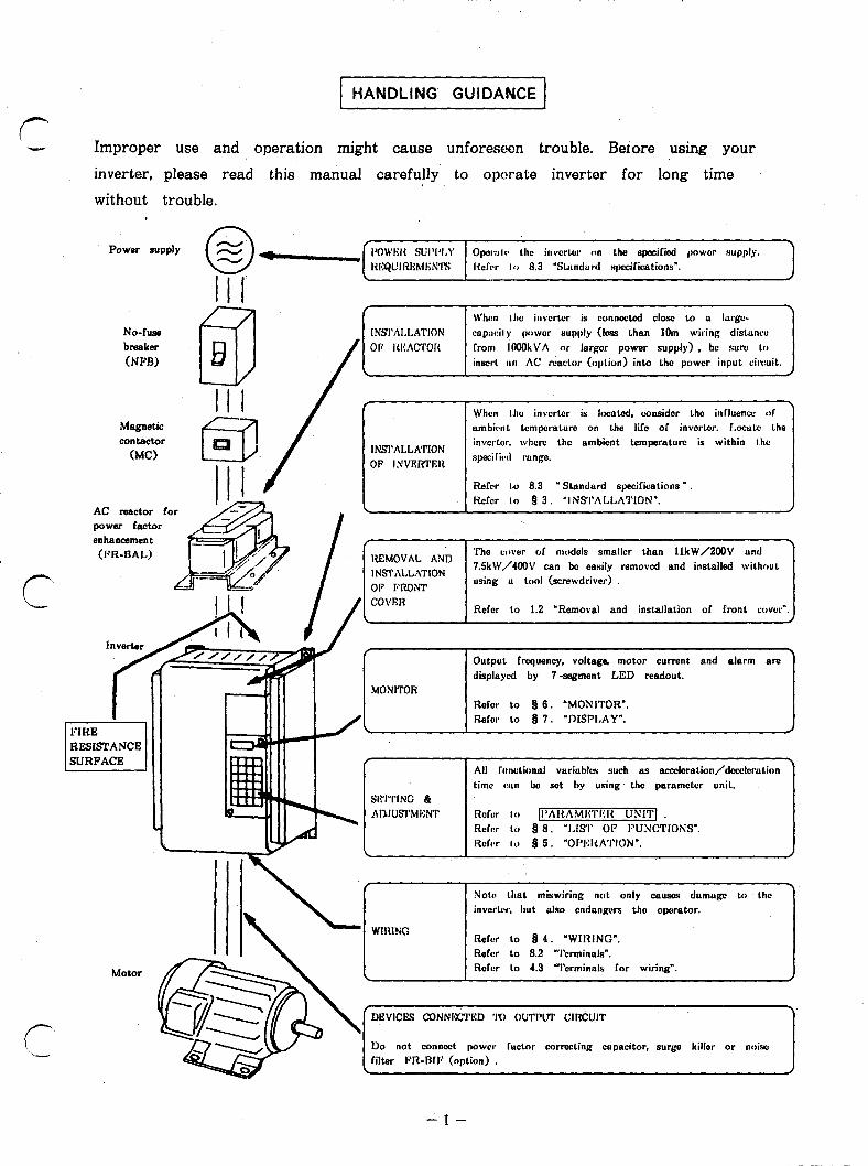
1 HANDLING GUIDANCE 1
Improper use and operation might cause unforeseen trouble. Betore using your
inverter, please read this manual carefully to operate inverter for long time
without trouble.
No-fuse breaker
(NPB)
When the icvcrtcr is connected close LO a lurgc- capwily lwwcr supply (Ins than 1Om wiring distonw lrom IOOOkVA or lorgcr power supply) , bc sure 1.0 inscrl. an AC reactor (option) inlo Lhc power input ciwuit.
/
Magnetic contactor
(MC)
,
INSI’ALLATION OF I.VVERTRIZ
When the invortcr is located, coasidcr the in&mu, 111 ambirnt temperature on the life of invcrtcr. I.ocutc the invcrlcr. whcrc the ambient temperaturn is within l.hc speGic~d range.
I - Refer 1.0 8.3 ” Standard specifications .
AC reactor for power factor enhancement
Refer lo 93. ‘lNSThLLA1’ION”.
7 Rl?MOVAL AND
The cover of models smallcr than llkW/2OOV and
INSI’ALLATION 7SkW/4OOV can be easily removed and installed without
OF PRONT using u LOOI (screwdriver)
Refer to 1.2 ‘Removal and installation of front cover”. J
MONITOR
Output frequency, voltage, motor current and alarm are dbplaycd by 7-segment LED readout.
Rdcr LO 9 6. ‘MONlTOR”. Rofcr to 8 7. “DISPLAY”.
A
time wn bc set by using the paramctcr unit.
Not+ that mixwiring not only ~1~80s damogc to the invcrtrr, but also cndongers the operator.
Refer lo I) 4. ‘WIRING”.
Mom
Refer LO 8.2 “Terminals’. Refer to 4.3 “Terminals Ior wiring”.
‘DEVICES CONNlGI’I’E:D ‘I’0 OUTPUT CIRCUIT \
Do not connect power Tactor correcting capacitor, surbw killer or n&c filter FR-RIP (oplion) .
\. J

8 1. CONSTRUCTION
1.1 External views and name of each part
0 .FR-2220-0.4K(~)-11K0, FR-Z240-2.2K(P)-7.5KCP)
~~ -
FRONT VIEW
Chassis heatsink (die cast)
\f-- , Rating plate
- ALARM indicator lamp
. POWER lamp
- LED Readout
- Parameter unit (For models having no parameter unit. an accessory cov*r is installed hem.)
Discharge resistor for brake (regenerative brake r&i&or) BACK VIEW
(For FR-Z220-0.4K)
l FR-Z220-15K-55K, FR-Z240-llK-55K
- POWER. atid ALARM indicator lamps
- A-ory cover (made of steel) When a parameter unit is used, remove this cover and .instaU the paraineter unit.
3
0
/ . . . ..3 .
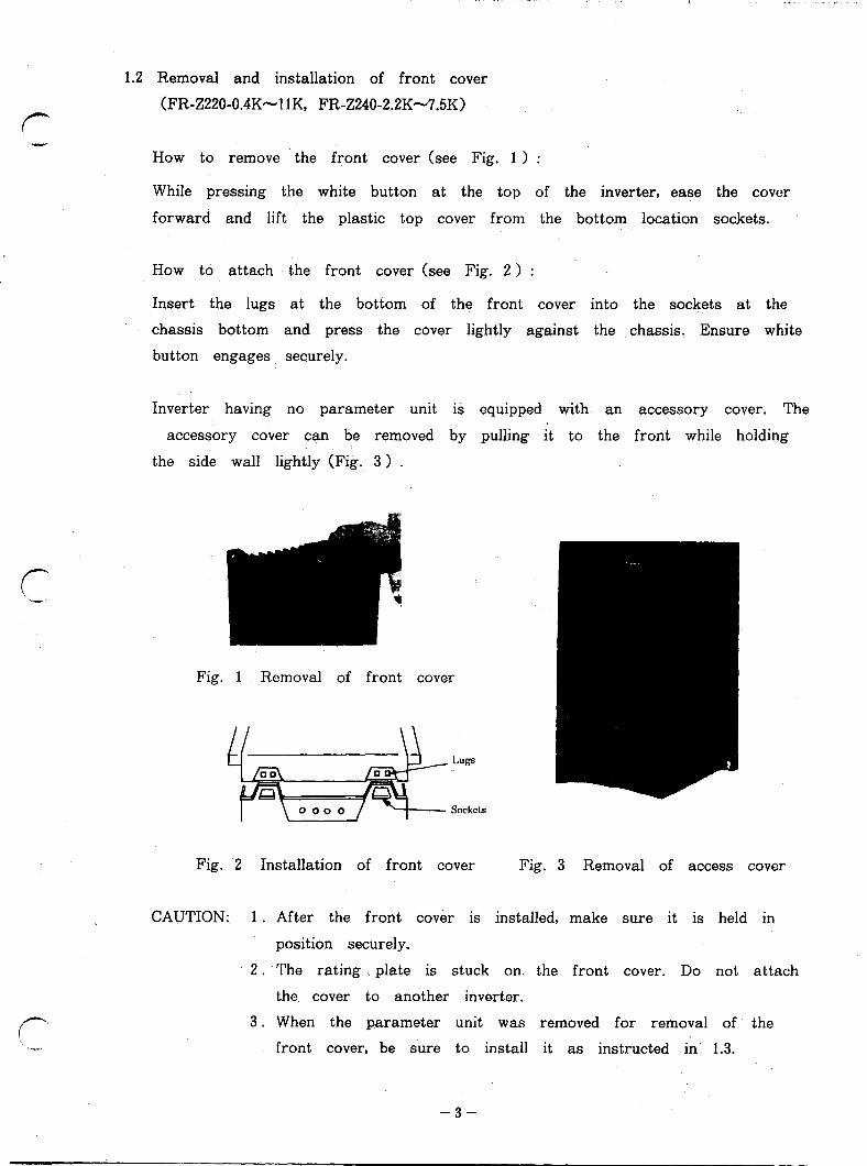
1..2 Removal and installation of front cover
(FR-Z220-0.4K--11 K, FR-Z240-2.2K-7.5K) f-
How to remove the front cover (see Fig. 1 ) :
While pressing the white button at the top of the inverter, ease the cover
forward and lift the plastic top cover from the bottom location sockets.
How to attach the front cover (see Fig. 2 ) :
Insert the lugs at the bottom of the front cover into the sockets at the
chassis bottom and press the cover lightly against the chassis. Ensure white
button engages securely.
Inverter having no parameter unit is equipped with an accessory cover. The
accessory cover can be removed by pulling it to the front while holding
the side wall lightly (Fig. 3 ) .
Fig. 1 Removal of front cover
Fig. 2 Installation of front cover Fig. 3 Removal of access cover
CAUTION: 1 . After the front cover is installed, make sure it is held in
position securely,
2, The rating plate is stuck on. the front cover. Do not attach
r --.
the cover to another invertor.
3. When the parameter unit was removed for removal of the
front cover, be sure to install it as instructed in 1.3.
-3-
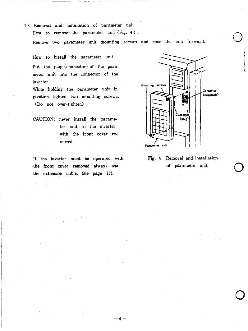
1.3 Removal and installation of parameter unit How to remove the parameter unit (Fig. 4 > : i
Remove two parameter unit mounting screws and ease the unit forward.
How to install the parameter unit:
Put the plug (connector) of the para-
meter unit into the connector of the
inverter.
While holding the parameter unit in
position, tighten two mounting screws.
(Do not over-tighten)
CAUTION: never install the parame-
ter unit to the inverter
with the front cover re-
moved.
Connector hc%ptacle)
If the inverter must be operated with
‘the front covw removed always use the extension cable. See page 113.
Fig. 4 Removal and installation
of parameter unit 0
0
-4-

b 2. UNPACKING AND CHECKING
After unpacking the inverter, check the following points.
(11 Check the rating plate on the front cover of inverter to make sure the
model and output ratings meet your order.
(21 Check that the inverter has not been damaged during transportation. Report damage immediately.
a > To the carrier b > To the inverter supplier
Invc&r model
Applicable motor
Line voltage and
Serial k
Pig. 5 Rating plate
INVERTER MODEL DESIGNATION.
FR-224003.7KP-UL
pcz@iJ- L < yI+-%q KILOWATT
I SylllbOl Volta@ clam SpllbOl Appl=bb
motor c8pacity SyUlbOI ParalMtw unit
zm 2OOV 0.4 capacity k P Providad akoun in Wnm
2240 4OOV 55 of LW. NOM Nona
-5-
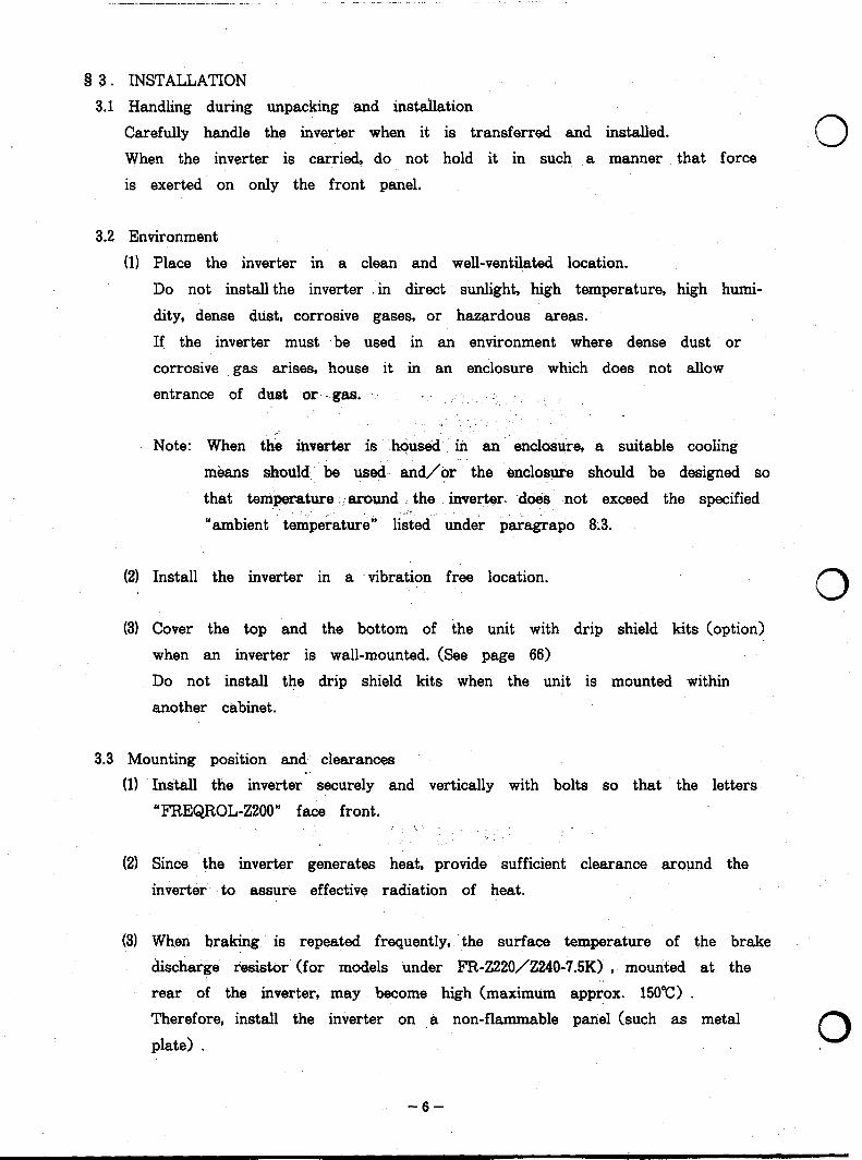
8 3. INSTALLATION 3.1 Handling during unpacking and installation
Carefully handle the inverter when it is transferred and installed.
When the inverter is carried, do not hold it in such a manner that force
is exerted on only the front panel.
3.2 Environment
(1) Place the inverter in a clean and well-ventilated location.
Do not install the inverter . in direct sunlight, high temperature, high humi-
dity, dense dust, corrosive gases, or hazardous areas.
If the inverter must .be used in an environment where dense dust or
corrosive gas arises, house it in an enclosure which does not allow
entrance of dust or gas. .. .
Note: When the inverter is ..hous&d : in an enclosure, a suitable cooling
means should be used and/or the enclosure should be designed so
that temperature . around the inverter. do& not exceed the specified
“ambient t temperature“ listed under paragrapo 8.3.
(2) Install th e inverter in a vibration free location. 0 (31 Cover the top and the bottom of the unit with drip shield kits (option)
when an inverter is wall-mounted. (See page 66)
Do not install the drip shield kits when the unit is mounted within
another cabinet.
3.3 Mounting position and- clearances
(1) Install th e inverter securely and vertically with bolts so that the letters
“FREQROL-Z200” face front.
(2) Since the inverter generates heat, provide sufficient clearance around the
inverter to assure effective radiation of heat.
(31 When braking is repeated frequently, the surface temperature of the brake
discharge resistor (for models under FR-Z220/Z240-?.5K) , mounted at the ., rear of the inverter, may become high (maximum approx. 150°C) .
Therefore, install the inverter on a non-flammable panel (such as metal
plate) . p
-6-
.,-
r ‘W
r‘
--- ---- I?
1Wmm ( 4 ‘1 or mGre
0 FREQROL-2200
1OOmm (4”) or more 1OOmm (4”) or more
or mot-c
spaces to aaun spaces to aaun Air stream r Air stream r good cooling effect. good cooling effect. AA,: AA,:
/ / 1: / 1: / 0 0 / /
I / /
i 2 2 / / I I
In*lw* In*lw* / /
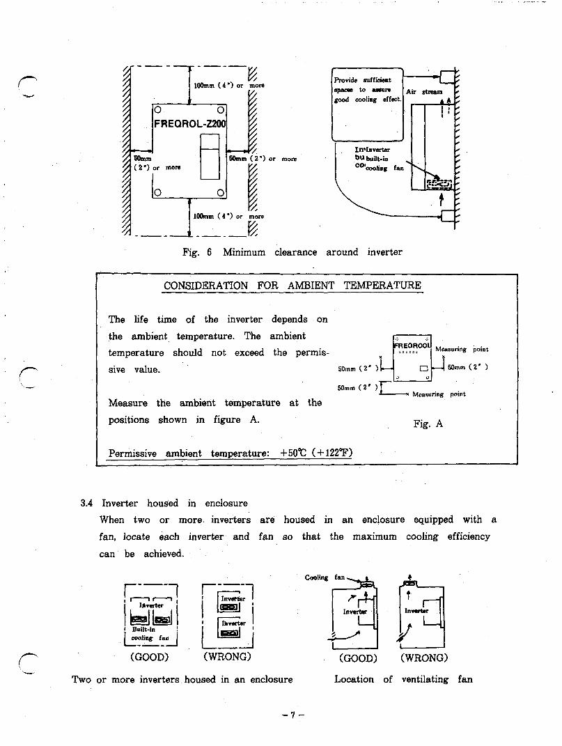
Fig. 6 Minimum clearance around inverter
CONSIDERATION FOR AMBIENT TEMPERATURE
The life time of the inverter depends on
the ambient temperature. The ambient temperature should not exceed the permis-
sive value. 50mm (2’ 1
5Omm (2’ ) Moamwing point
Measure the ambient temperature at the
positions shown in figure A. Fig. A
Permissive ambient temperature: +5O”c (+ 122°F)
3.4 Inverter housed in enclosure
When two or more. inverters are housed in an enclosure equipped with a
fan, locate each inverter and fan so that the maximum cooling efficiency
can be achieved.
(GOOD) (WRONG)
I--"1 i Iawtter 1
II lpeD i
Two or more inverters housed in an enclosure
(GOOD) (WRONG)
Location of ventilating fan
-?-
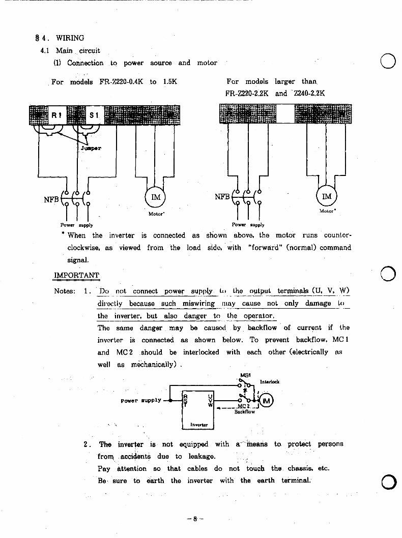
Q 4. WIRING
4.1 Main circuit.
(1) Connection to power source and motor
For models FR-%220-0.4K to 1.5K For models larger than
PR-Z220-2.2K and Z240-2.2K
Power supply I I I
Power supply
* When the inverter is connected as shown above, the motor runs counber-
0
clockwise, as viewed from the load side, with “forward” (normal) command
signal.
IMPORTANT
Notes: 1 . DCJ not ‘connect power supply to the output terminals (II, V, W) -._ _ ..- L __...____. _. ..__ ---. .-- ---- .-- directly because such miswiring n~ay cause not only damage Lo --.- _ . -- -._ . _._.- - _ .- the inverter, but also danger to the operator. ------ -..-_ The same danger ..may be caused by backflow of current if the
invorter is connected as shown below. To prevent backflow, MC 1
and MC 2 .should be interlocked with each other (electrically as
well as m&hanically) .
2. The inverter is not equipped with a” means to. protect persons
-from .acci&nts due to leakage. ‘. . :’
Pay attention so that cables do not touch the. chassis, etc.
‘Be’ sure to earth the inverter with the earth terminal.
0
0 - 8 --

r
(- -.I
3. If magnetic contactor (MC) is not inserted on the inverter primary
side and a power failure occurs for a short time (instantaneous
power failure) , the inverter will restart automatically at the same
time as the power source is restored.
If it is likbly that this automatic restart may cause damage to
the machine or persinnel, connect .(MC> so that restart is possible
only after’ safety is verified.
For a better understanding, refer to the following diagrams and
descriptions:
Para. 4.3 “Wiring diagram”
Para. 8.2 “Terminals for wiring”
Para: 8.1 “Block diagram”
- CAUTION FOR WIRING OF PERIPHERAL DEVICES
When MC, NFB and other peripheral devices are being connected to the
inverter, cover the inverter to prevent wire chips, screws and other foreign
matter from entering into the inverter through slits and other openings of
the inverter.
(21 Connection of discharge resistor for increased braking (regenerative brake
resistor unit ****** option)
A built-in discharge resistor is been connected to terminals P and PR
-internally, .as standard. ’
However when braking operation is particularly frequent and may exceed
the thermal capacity of the built-in resistor, replace the built-in discharge
resistor with optional discharge resistor unit.
Apply this option with care, due to increased heat losses which have to
be dissipated.
- 9.’
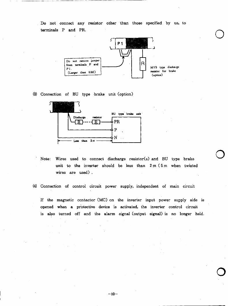
Do not connect any resistor other than those specified by us, to
terminals P and PR.
-
\ --* I3 Yh
? >
-J
MYS type
LT resistor for (option)
discharge brake
0
(3) Connection of BU type .brake unit (option)
BU type braka unit
.’ Note: Wires used to connect discharge resistor(s) and BU type brake 0 unit to the inverter should be less than 2 m (5 m when twisted
wires are used) .
(41 Connection of control circuit power supply, independent of main circuit
If the magnetic contactor (MC) on the inverter input power supply side is
opened when a protective device is activated, the inverter control circuit
is also turned off and the alarm signal (output signal) is no longer held.
0
I -lO-
r ‘v
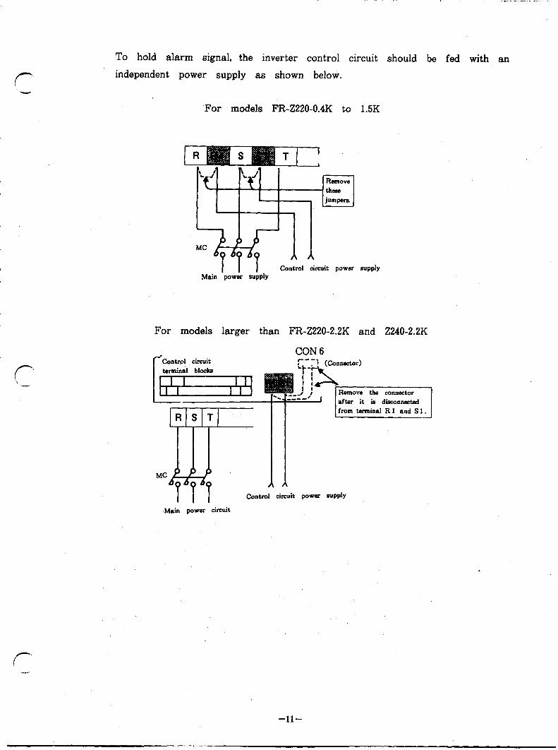
To hold alarm signal, the inverter control circuit should be fed with an
independent power supply as shown below.
‘For models FR-Z220-0.4K to 1.5K
RrmOW
these jumpers.
Main ‘povJk control oircuit power supply
For models larger than FR-Z220-2.2K and Z240-2.2K
CON 6
from tennina RI and Sl.
Control circuit power SuPPlY
.Main power circuit
-ll-
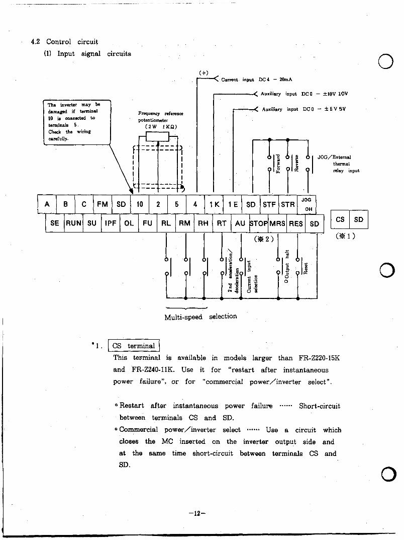
4.2 Control circuit
(1) Input signal circuits
darn4 if terminal 10 is connected to
Check the wiring
Frequency reference
(2W 1KQ)
c_( Current input DC4 - 20mA
0 -< Auxiliary input DC 0 - +lOV 1OV
___( Apxiliary input DC0 - f 5 V SV
A B C FM SD 10 2 5 4 1 K 1 E SD STF STR JoG
SE RUN SU IPF OL FU RL RM RH RT AU STOPMRS RES SD
Multi-speed selection
uzl CS SD
This terminal is available in models larger than FR-Z220-15K
and FR-Z240-11K. Use it for “restart after instantaneous
power failure”, or for “commercial power/inverter select “.
0 Restart after instantaneous power failure ****** Short-circuit
between terminals CS and SD.
0 Commercial power/inverter select ***-** Use a circuit which
closes the MC inserted on the inverter output side and
at the same time short-circuit between terminals CS and
SD.
.O
-12-
For details, refer to the technical information.
’ f-
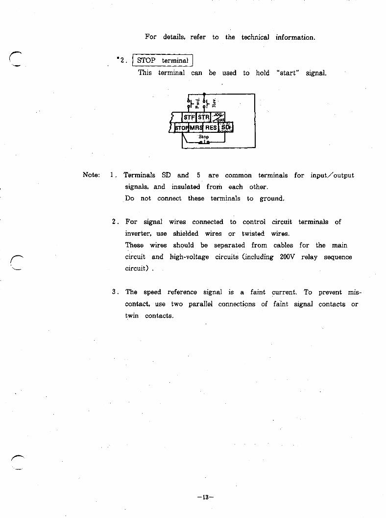
*2. STOP terminal
This terminal can be used to hold “start” signal.
1 Note: 1 . Terminals SD and 5 are common terminals for input/output
signals, and insulated from each other.
,Do not connect these terminals to ground.
2. For signal wires connected to control circuit terminals of
inverter, use shielded wires or twisted wires.
These wires should be separated from cables for the main
circuit and high-voltage circuits (including 200V relay sequence
circuit) .
3. The speed reference signal is a faint current. To prevent mis-
contact, use two parallel connections of faint signal contacts or
twin contacts.
-13-
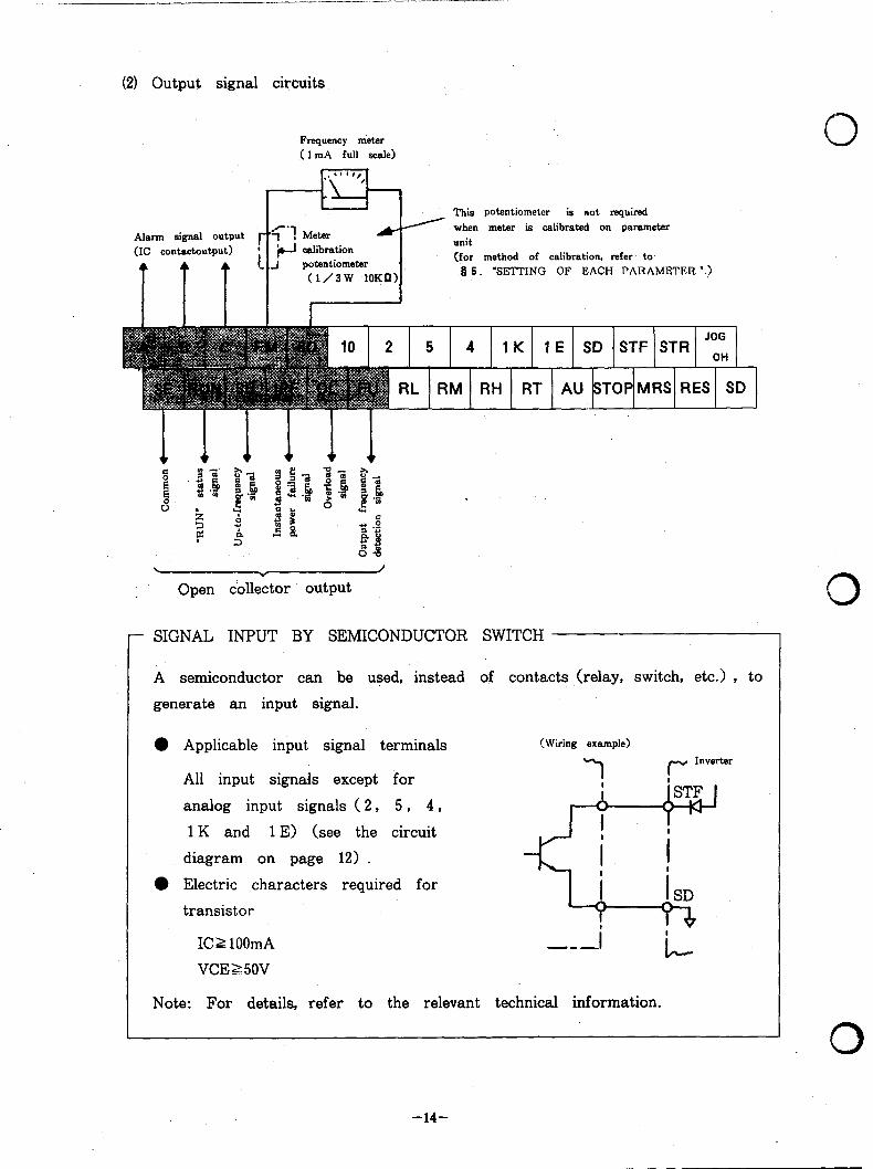
(21 Output signal circuits
Frequency nieter ( 1 mA full scale)
Alarm signal output (IC contactoutput)
(1/3W lOKn>
This potentiometer is not required when meter ie calibrated on parameter
(for method of calibration. refer. to 8 5. ‘SETTING OF EACH PARAMETER “.>
. Y
/
Open collector output
- SIGNAL INPUT BY SEMICONDUCTOR SWITCH
A semiconductor can be used, instead of contacts (relay, switch, etc.) , to
generate an input signal.
0 Applicable input signal terminals
All input signals except for
analog input signals ( 2, 5 , 4,
1 K and 1 E) (see the circuit
diagram on page 12) .
l Electric characters required for
transistor
(Wiring example)
IC1 lOOmA A--
VCEZ 50V
Note: For details, refer to the relevant technical information.
0
0
0
-14-
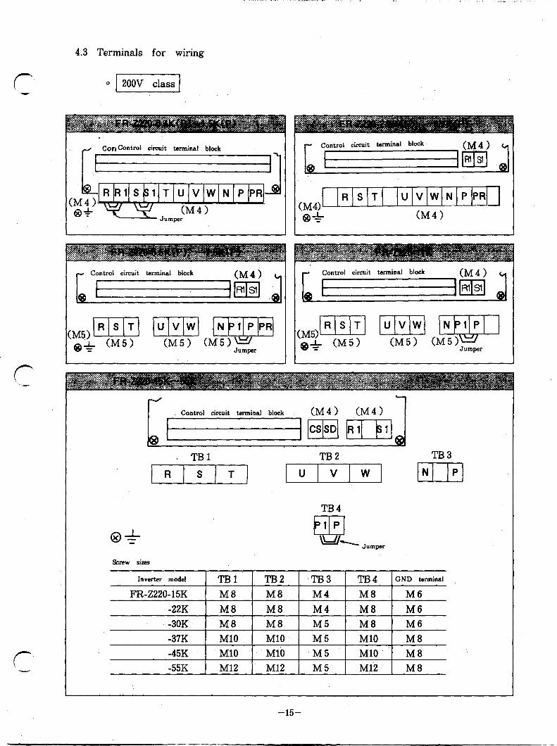
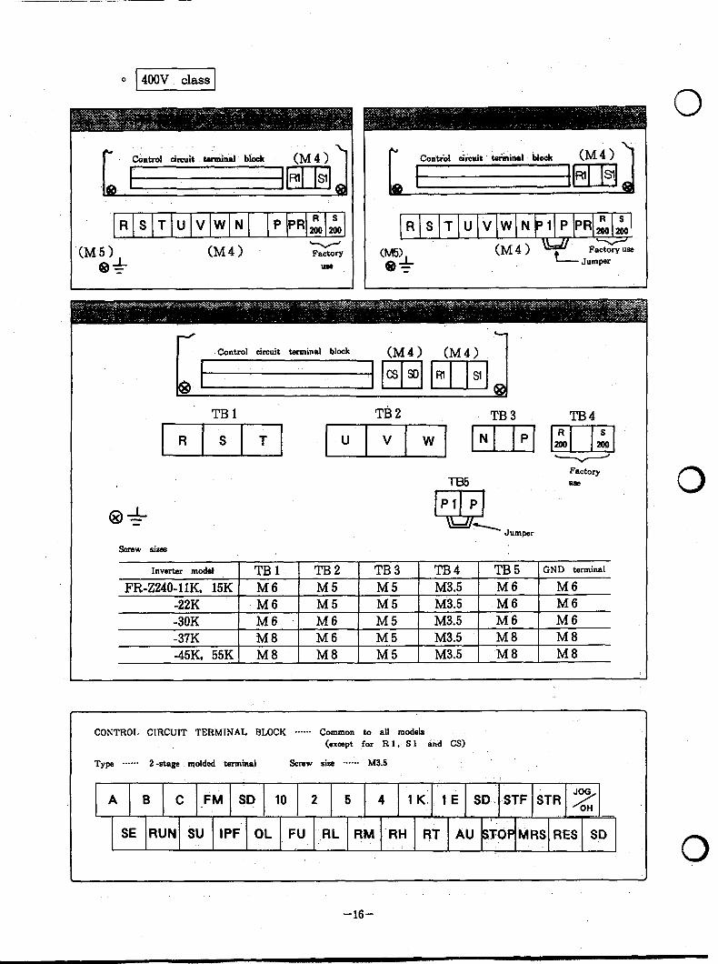
4.3 Terminals for wiring
Concontrd circuit terminal block
U VW N PPR
- Control circuit terminal block
(M51m w ,Mp e+ CM51 ‘Jumper
rc/ v
Control circuit terminal block (M4) (M4)
f=====jpqm
. TBl TB2 TB3
TB4
Screw sizes
.RSTUVWN PPRZA R S ‘T U V W N 1 PPRz;i
CM51 (M4) e+
Factory (M5> (M4) wc Faxse
use e+ Jumper
-
J c1
-Control circuit tanninal block (M4) (M4)
TBl Tti2 TB3 TB4
Factory ua?
screw sizes
Inverter model TBl TB2 TB3 FR-Z240-llK, 15K M6 M 5 MS
-22K M6 M5 M5 -3OK M6 M6 MS -37K M8 M6 M5 -45K, 55K M8 M8 MS
TB4 TB5 GND terminal
M3.5 M6 M6 M3.5 M6 M6 M3.5 M 6 M6 M3.5 M 8 M8 M3.5 M8 M8
CONTROL CIRCWT TERMINAL BLOCK ****+* Common to all models (except for Rl. Sl aid CS)
SE RUN SU IPF OL FU RL qM -RH -RT AU STOP MRS RES SD
-16-
0

4.4 Field wiring reference table
(+- - For screw torque, crimping terminals and crimping tools, refer to the following table.
Note ( * 1) Manufacturer: AMP INCORPORATED, HARRISBURG, PA 17105 l
PHONE: 717-564-0100 TWX: 510-657- 4 ( * 2 > Use copper wire only
Inverter model
FR-2220-15K
FR-2220-22K
FR-Z220-30K
TB1,2,4 70 2-;;;%;;-3 Hy9i70pl AWG4 75°C
- Dies 48754- 1
TB3 13 32968 59239 AWGlO 75°C TB1,2,4 70
E;; H%:7?? AWG2 75°C
- 326896 Dies 48755-l
TB3 13 32968 59239 AWGlO 75°C TB1,2,4 70 EY: ;rr& 9 r$d AWGl/O 75°C
328526 69325-3 Head
69066 Dies
48756- 1 TB3 23 322153
322005 Hyg;70;l AWG6 75°C
Dies 48753- 1
Note: Terminal block location is shown in page 15.
-17-

Inverter model
Screw torque Crimping terminals type Wire size and temp-rating and tool type ( * 1) (* 2)
Terminal (Pound Crimping Crimping Size temp-rating block Na -Inch) terminals tools
FR-2220-37K TB1,2,4 131
TB3 23
FR-Z220-45K TB1,2,4 131
TB3 23
FR-Z220-55K TB1,2,4 219
TB3 23
322094 Foot Operated AWGS/O 75°C
;E! Power Unit
69325-3 Head
69066 Dies
48758-l 322153 AWG6 75°C 322010
Hygi70p1
Dies 48753- 1
Ei Foot Operated AWG4/0 75°C Power Unit
322601 69325-3 324196 Head
69066 Dies
48759-l
E; Hygi70y1 AWG6 75°C
Dies - 48753-l
322254 Foot Operated 300MCM 75°C Power Unit
69325-3 Head
69060 Dies
48816
Ei Hygi70;l AWG6 75°C
Dies - 48753- 1
Note: Terminal block location is shown in page 15.
Inverter model
Note: Terminal block location is shown in page 16. -18-
0
0

Screw torque Crimping terminals type Wire size and temp-ratink and tool type (* 1) (*2>
Inverter model Terminal (Pound Crimping Crimping Size temp-rating block Na -Inch) terminals tools
FR-Z240-11K TB1,5 40 322049 Hand tool AWG8 75°C FR-ZZQO-15K
%E 59974- 1
Dies 48752- 1
TB2,3 23 Et!
Hand tool AWG8 75°C 59974-l
322002 Dies 322154 48752-l
FR-Z240-22K TB1,5 40 322051 H”5”g&f;’
AWG6 75°C
w Dies 48753-l
TB2,3 23 ;I%
Hygi70~l AWG6 75°C
3; Dies
48753- 1 FR-Z240-30K ,TB1,2,5 40 322051 Hagngdg7F;l AWG6 75°C
%2 Dies - 48753-l
TB3 23 E%! H”5”9d97;P’
;Ei; Dies
48753- 1
FR-Z240-37K TB1,5 70 E;i Hyg;7~p1
AWG2 75°C
322013 Dies 48755-l
TB2 40 EfE 7%7?P’
AWG2 75°C
x; Dies -
48755-l
?3 23 EE!i “%$72’
AWG6 75°C
322153 Dies - 322005 48753-l
FR-Z240-45K TB1,2,5 70 ;;;:;;
Ha;lgdgorl AWGZ 75°C
322013 Dies - 48755- 1
TB3 23 Ei!!
Hsgngdg70yl AWG6
EE Dies
48753-l FR-Z240-55K TB1,2,5 70
EE Foot rated AWGl/O
77 75°C
Power nit 328526 69325-3
Head 69066
Dies 48756-l
TB3 23 !Ei!l
Hand tool AWG6 75°C 59974-l
322153 Dies 322005 48753-l
Note: Terminal block location is shown in page 16. -19-


(2) Check that th ere is no short-circuit due to wire offcut, etc.
(31 Check that h t s or -circuit and earth fault do not exist in the output circuit.
(4) Check that all screws, terminals and other fasteners. are tight.
r CAUTION FOR INSULATION RESISTANCE TEST WITH MEGGER
0 For insulation resistance test with megger, refer to Q 6 . 6.2, (3).
0 Never apply the test voltage to the control circuit terminals and across
the inverter terminals.
5.3 Pi-e-operation settings and adjustments
The inverter itself does not have control devices to set or adjust by operator,
such as select switch and potentiometer. (As with previous models of FREQROL)
(- -- When settings (accelation/deceleration time, electronic thermal relay setting, etc.)
must be changed, the parameter unit (FR-PUO 1 > is used (for the initial settings,
refer to chapter 98.1.
For methods of changing parameter setting, refer to the description “HANDLING
AND OPERATIGN OF PARAMETER UNIT”. (p. 69 - p. 113)
r -
-2l-
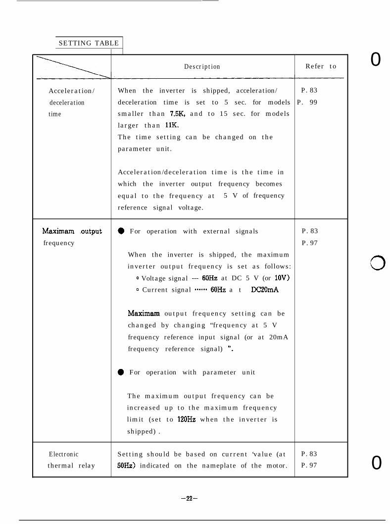
SETTING TABLE
Acceleration/
deceleration
time
Description Refer to
When the inverter is shipped, acceleration/ P. 83
deceleration time is set to 5 sec. for models P. 99
smaller than 7.5K, and to 15 sec. for models
larger than 11K.
The time setting can be changed on the
parameter unit.
Acceleration/deceleration time is the time in
which the inverter output frequency becomes
equal to the frequency at 5 V of frequency
reference signal voltage.
Maximam .output
frequency
0 For operation with external signals P. 83
P. 97
When the inverter is shipped, the maximum
inverter output frequency is set as follows:
0 Voltage signal --- 6OHz at DC 5 V (or lOV>
0 Current signal --+-*- 60Hz a t DC20mA
Maximam output frequency setting can be
changed by changing “frequency at 5 V
frequency reference input signal (or at 20mA
frequency reference signal) “.
0 For operation with parameter unit
The maximum output frequency can be
increased up to the maximum frequency
limit (set to 120Hz when the inverter is
shipped) .
Electronic Setting should be based on current ‘value (at P. 83
thermal relay 50Hz) indicated on the nameplate of the motor. P. 97
0
0
0
-22-
- - . . - . . , . . . - . I . - . . . . . . . . . . - “._. I . . . , , , 4 *“c - . . . . . . - - - . -
Description Refer to
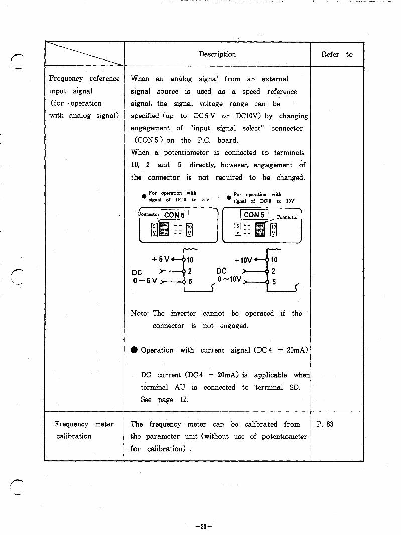
Frequency reference When an analog signa from an external
input signal signal source is used as a speed ‘reference
(for . operation signal, the signal voltage range can be
with analog signal) specified (up to DC 5 V or DClOV) by changing
engagement of “input signal select” connector
(CON5 > on the P.C. board.
When a potentiometer is connected to terminals
10, 2 and 5 directly, however, engagement of
the connector is not required to be changed.
. 1”’ operation with For operation with SIgnal Of DC O tO S V l sipa] of DC0 b. 1OV
;/f (;:,;yf (
Note: The inverter cannot be operated if the
connector is not engaged.
0 Operation with current signal (DC4 - 20mA)
DC current (DC4 - 20mA) is applicable when
terminal AU is connected to terminal SD.
See page 12.
Frequency meter
calibration
The frequency meter can be calibrated from P. 83
the parameter unit (without use of potentiometer
for calibration) .
-23-
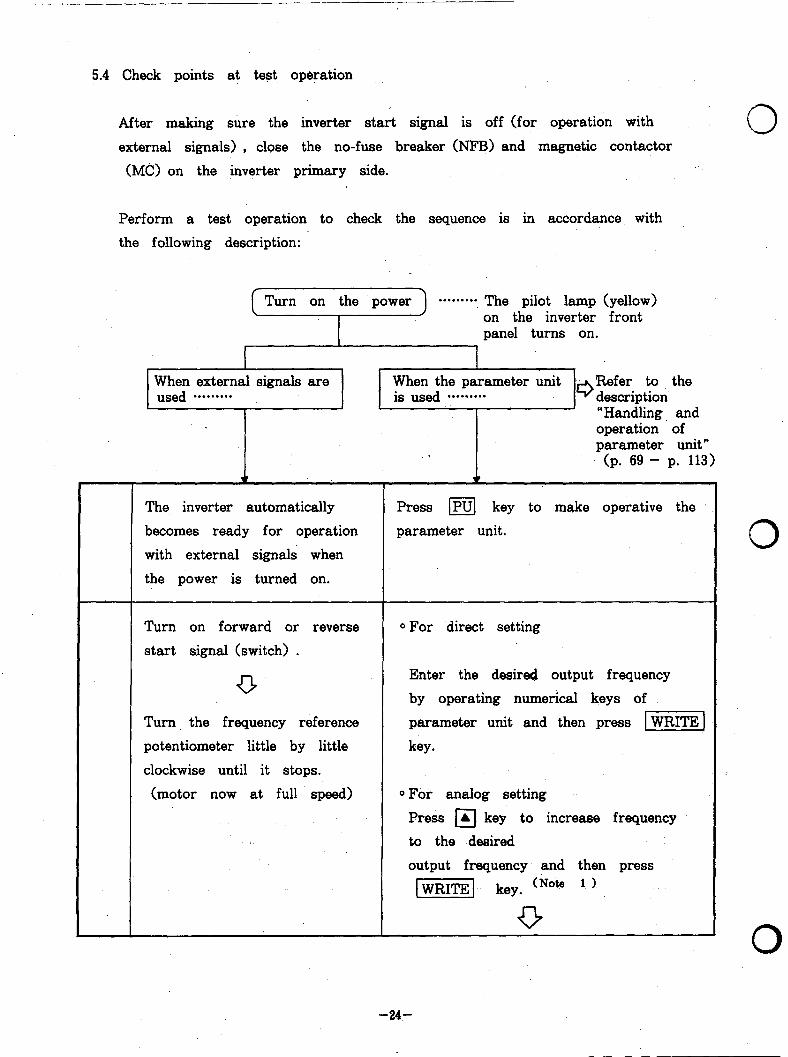
5.4 Check points at test operation
After making sure the inverter start signal is off (for operation with
external signals) , close the no-fuse breaker (NFB) and magnetic contactor
(MC) on the inverter primary side.
0
Perform a test operation to check the sequence is in accordance with
the following description:
Turn on the power ********‘. The pilot lamp (yellow) on the inverter front panel turns on.
When external signals are used . . . . . . . . .
When the parameter unit Refer to the is used . . . . . . . . . 9 description
“Handling and operation of parameter unit”
(p. 69 - p. 113) w
The inverter automatically
becomes ready for operation
with external signals when
the power is turned on.
‘I
Press m key to make operative the
parameter unit.
Turn on forward or reverse
start signal (switch) .
0 For direct setting
0
Turn the frequency reference
potentiometer little by little
clockwise until it stops.
(motor now at full speed)
Enter the desired output frequency by operating numerical keys of
parameter unit and then press pizeiq
key.
0 For analog setting
Press m key to increase frequency to the desired
output frequency and then press
-1 key. (Note * ’
-0
-24-
0
0
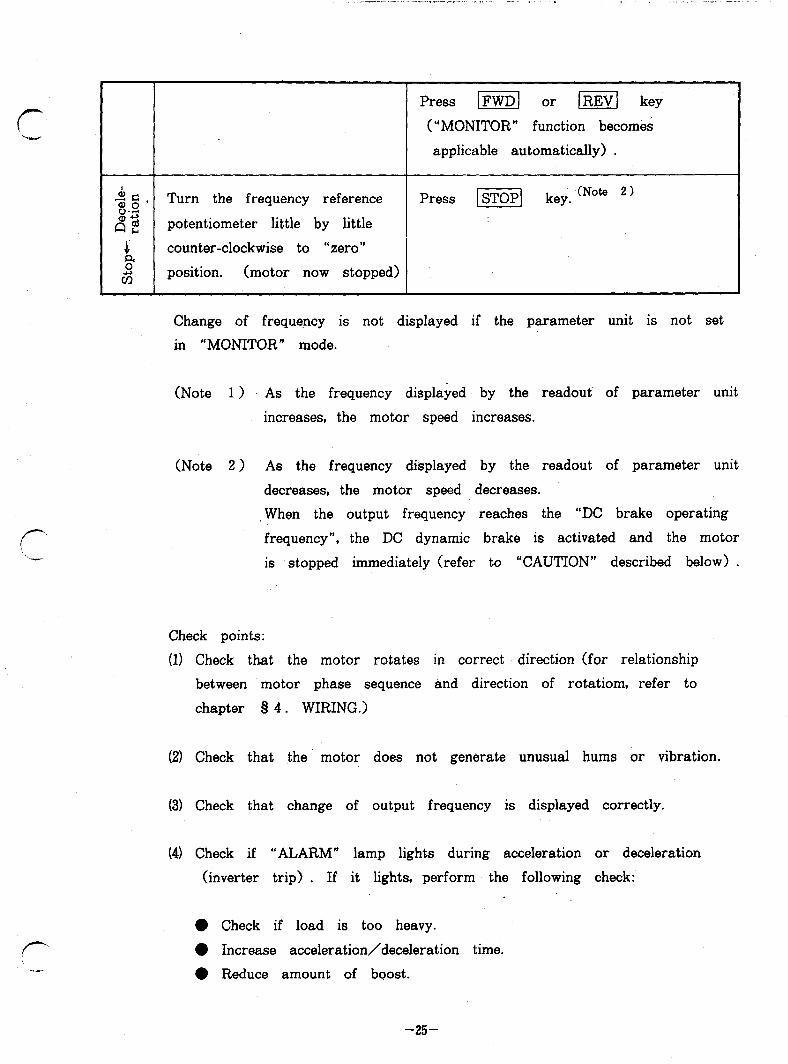
Press I[ or @%$ key
(“MONITOR” function becomes
applicable automatically) .
.$g* Turn the frequency reference Press -1 key. (Note 2, 8-r: ad potentiometer little by little
s counter-clockwise to “zero” 4
6 position. (motor now stopped)
1 : L*
f- -
Change of frequency is not displayed if the parameter unit is not set
in “MONITOR” mode.
(Note 1) As the frequency displayed by the readout of parameter unit
increases, the motor speed increases.
(Note 2 > As the frequency displayed by the readout of parameter unit
decreases, the motor speed decreases.
When the output frequency reaches the “DC brake operating
frequency”, the DC dynamic brake is activated and the motor
is stopped immediately (refer to “CAUTION” described below) .
Check points:
(1) Check that the motor rotates in correct direction (for relationship
between motor phase sequence and direction of rotatiom, refer to
chapter 8 4. WIRING.)
(2) Check that the motor does not generate unusual hums or vibration.
(3) Check that change of output frequency is displayed correctly.
(4) Check if “ALARM” lamp lights during acceleration or deceleration
(inverter trip) . If it lights, perform the following check:
l Check if load is too heavy.
0 Increase acceleration/deceleration time.
l Reduce amount of boost.
-25-

CAUTION:
(11 If the forward (STF) and reverse (STR) start signals turn on at the same ’
time, the inverter will not start. If these signals turn on simultaneously
during operation, the motor is decelerated (the inverter output frequency
decreases) to a stop. _ .
(2) Durpng deceleration, the DC dynamic brake is actuated for 0.5 seconds when
the inverter output frequency decreases to less than the DC brake frequency
(below the start frequency, when speed reference signal voltage (or current)
is reduced gradually) .
During this DC dynamic braking period, the motor may generate a high-
pitched hum, but this is not a failure, nor a sign of trouble. This is
normal during DC braking.
(31, If “ALARM” lamp lights and the motor stops after coasting, check that the
motor has stopped completely and then reset the inveyter to shut off the
power, using the reset terminal.
0
0
.:
r 0
-26-

8 6. MAINTENANCE AND INSPECTION
f- %me- The inverter is a piece of static equipment consisting mainly of semiconduct-
or elements.
To prevemt trouble with the inverter, due to high temperature, humidity, dust,
intense vibration, component deterioration, etc., it is very important to perform
periodic inspection.
6.1 Caution for maintenance and inspection
r i-l
(1) Operator must check whether, power supply is ON or OFF by himself
to prevent misoperation by others.
(2) After the power is switched ’ off, the capacitor remains charged at high
voltage for a while.
Before making an pnspection, check that the CHARGE lamp on the P.C.
board is off, and voltage across the inverter main circuit terminals P
and N is below DC30V, using a multimeter, etc.
6.2 Inspection points
This invertey is equipped with the power pilot lamp and error (alarm)
display function. .
It is advisable that you familiarize yourself with the error display definitions.
Also note the normal settings of the electronic thermal relay, acceleration/
deceleration time, etc.
(1) Daily inspection
During daily operation, check the following:
(a) The motor operates properly.
(b) The environment is normal.
(cl The cooling system is normal.
(d) There is no unusual vibration and noise.
(e) There is no overheat and discoloration in any component of the
inverter .
-n-

During operation, check inverter input/output voltage with a multimeter.
(2) Periodic inspection
Check the followings periodically with the inverter stopped:
(a) Check that the cooling system is in good condition.
Clean air filters, etc.
(b) Screws, bolts, nuts and other fasteners may become loose with time,
due to vibration, thermal expansion/retraction, etc.
Retighten loose screws or other fasteners.
(c) Check if conductors and insulators are not corroded. or damaged.
(d) Measure insukation resistances.
(e) Check the cooling fan, smoothing capacitor, contactors and relays for
condition.
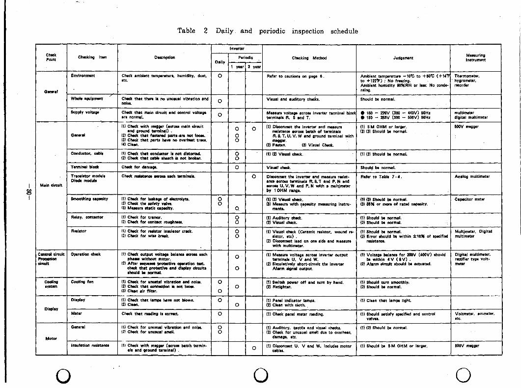
Table 2 shows the standard daily and periodic inspection schedule.
0
(3) Insulation resistance test with megger
(a) Before checking insulation resistances of the external circuits with a
megger, disconnect wires (cables) from all inverter terminals so that
test voltage is not applied to the inverter circuits.
(b) Conduct the insulation resistance test on the inverter main circuit
only, as shown in Fig. 7.
Do not conduct the test on the control circuit of inverter.
(c) To check the control circuits for continuity, use a multimeter (high
resistance range> . ,
Do not use a megger or buzzer to check.
0
-28-
I

Fig. 7
Motor -m-m-)
---VW
Ground trrminsl
Insulation resistance test with megger
t
Check Point Checking Item Dwcrlption
Inwrter
Periodic Dally .
1 ywr 2 year
Chocking Method Judgment Meaalurinp lnstrumrnt
Environnlwt Check ambient temperature, humidity, dust. 0 Rnhr to cautions on paga 6. Ambirnt temperature -1O’c to +SaC (+14f Thrrmomrar. etc. to +122’F) ; No frnxing. hygrometer.
Ambirnt humidity SOURH or lass: No con&- rnordrr
Gwwr*l ’ nrlng.
Whole rquipmont /
Chmk that thrra ir no unutud vibration and O Visual and auditory chock@. Should k normal. noita.
I supply voltage
Gmwd
Conductor. ublr
Check that main circuit and control voltaS* ore normal.
O Measure voltage (Iwo* inwrtrr terminal Mock 0 180 - 220; l:E 1 440:; ZO: multimeter torminrlr R. 8 and T. l 180 - digital multimater
(11 Check with meggw (across main circuit and ground tbrminal) . 0 0 HI Dlmomwct tha invutrr and mnrrure (1) 6M OHM or larger. WOV mwgtr
rrlstana across batch of terminals (2) (3) Should k normal. (2) Chock that fastenad parts.rre not loom. 13) Chock that porta hrw no owrhut trau. 8
R. S. T, LJ. V, W and around terminal with
14) Clwn. mwg9.r.
(2) Fasttm. (3) Visual Chock.
(1) Check that conductor is not dietort&. 8
(1) (2) Visual ahack. (1) (21 should bb normal. (21 Chack that cable rhuth i# not broken.
Tarmind block
Trrndstor module Diode module
Main circuit
Chnk for damago.
Check mist~nce acroa ah orminrls.
0 Viruel &ask. Should k normal.
0 Di@connect thr inwrtw and mratun resist- Refer to Table 7-4. An&S multimeter anca mron hrmlnals R.S.T and P. N and awon U. V. W and P. N with a multjmrtw by 1 OHM ron~r
Smoothing rpwity
AaIry. contactor
Rrirtor
(1) Chack tar lukap of rlactrdytt. (2) chuk thr wfety VdW. ‘3) Mwwn notit copuity.
(1) Chock for tramor. (2i Cheek for contact roughen.
(1) Check for resistor insulator crack. 12) Check for wlrr break.
(1) (21 Vi8ual thack. 8
(1) 0) Should k normal. Capwitor meter (3) Mea~un with capacity measuring instru- (3) 85% or man of rated wpacity.
0 ment8.
8 (1) Auditory check. (II Should br normal. (2) Visual c&k. (21 Should k normal.
(1) Should k normal. Multjmmr. Digital 8
(1) Vl8url ahack (Ceramic rrsictor. wound R- sirtor. 9tc) . (2) ;~ti;~uld k within f10% of sceified multimater
(2) Disconnect lrad on one sldr and measure with multim#rr.
:antrol circuit Operation chtok WOtUtiW :imuit
(1) Chrck output voltaga balmtea across wch phases without motor.
(2) After nquana prouetiw operation tact. chuk that protutlw and die& chita should k normal.
0
0
(1) Mearun volteg* acrow inwrtw output twmlnalo U. V and W.
(2) Simulativaly rhort-clreult the lnv& Alarm rlgnal output.
(1) Voltage balona for 2OSV (4OOV) should Digital multimrtrr. br wlthin 4V (8V) . rutlfior typ volt-
(2) Alarm &cult rhould k actuated. meter
phi mm
Dirplry
Motor
CodInS fan
Dirplay
Meter
Guwral
Insulation rrrirtatwa
(1) Cheek for unwtal vibration and noln. 0 (2) Chuk that wmutlon h not loon.
(1) Switch poww off and turn by h&d. (1) Should turn wnwthly8 0 (2) Should b normal.
(3) Ghan rlr flltar. 0 (2) Ratighan.
- -_ {:I Eh$ that Iamy have not blown. 0 (1) Panel indicator Iampc. (1) Clean that lamp light.
0 (2) Clrrn with cloth.
Chack that wading Is corract. 0 (II Chak panel meter reading. (1) Should satisfy specified and control Voltmeter, ammeter. VSIVU. etc.
(1) Check for unusual vibration and noisr. (21 Chrcl: for unusurf rmrll.
(1) Auditory. tactile and visual checks. (1) (2J Should k normal. (21 Check for unusual #mrll due to overheat,
dsmsgr etc.
(1) Check with nuggw (-roes batch trrmin- (1) Should ba 6M OHM or larger. MH)V mm elr and ground terminal) . 0 (1) Clbl,nnwt U. V and W. Includrc motor
.
0 0
Table 2 Daily and periodic inspection schedule
/ . 1.x. . ..^. i..____- _ -
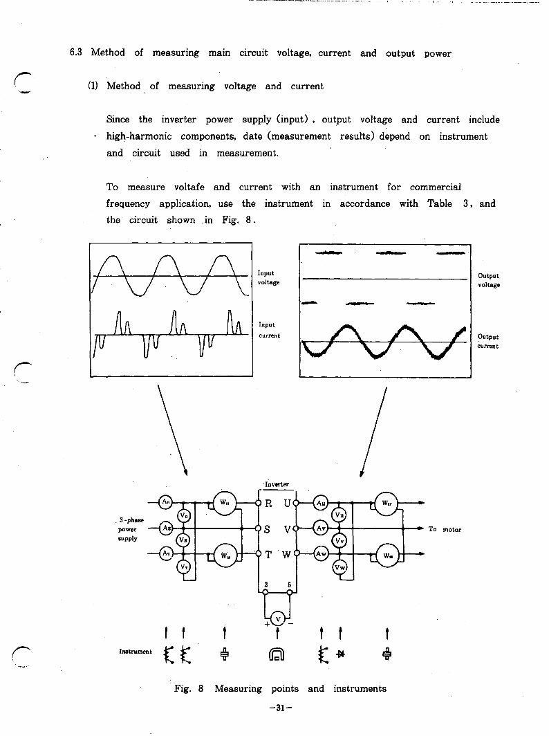
6.3 Method of measuring main circuit voltage, current and output power
(1) Method of measuring voltage and current
Since the inverter power supply (input) , output voltage and current include
* high-harmonic components, date (measurement results) depend on instrument
and circuit used in measurement.
To measure voltafe and current with an instrument for commercial
frequency application, use the instrument in accordance with Table 3, and the circuit shown .in Fig. 8.
3 -phase power
SUPPlY
Input VOltage
VwAi Av 1 ) 1
To
Fig. 8 Measuring points and instruments
motor
Output voltage
output current
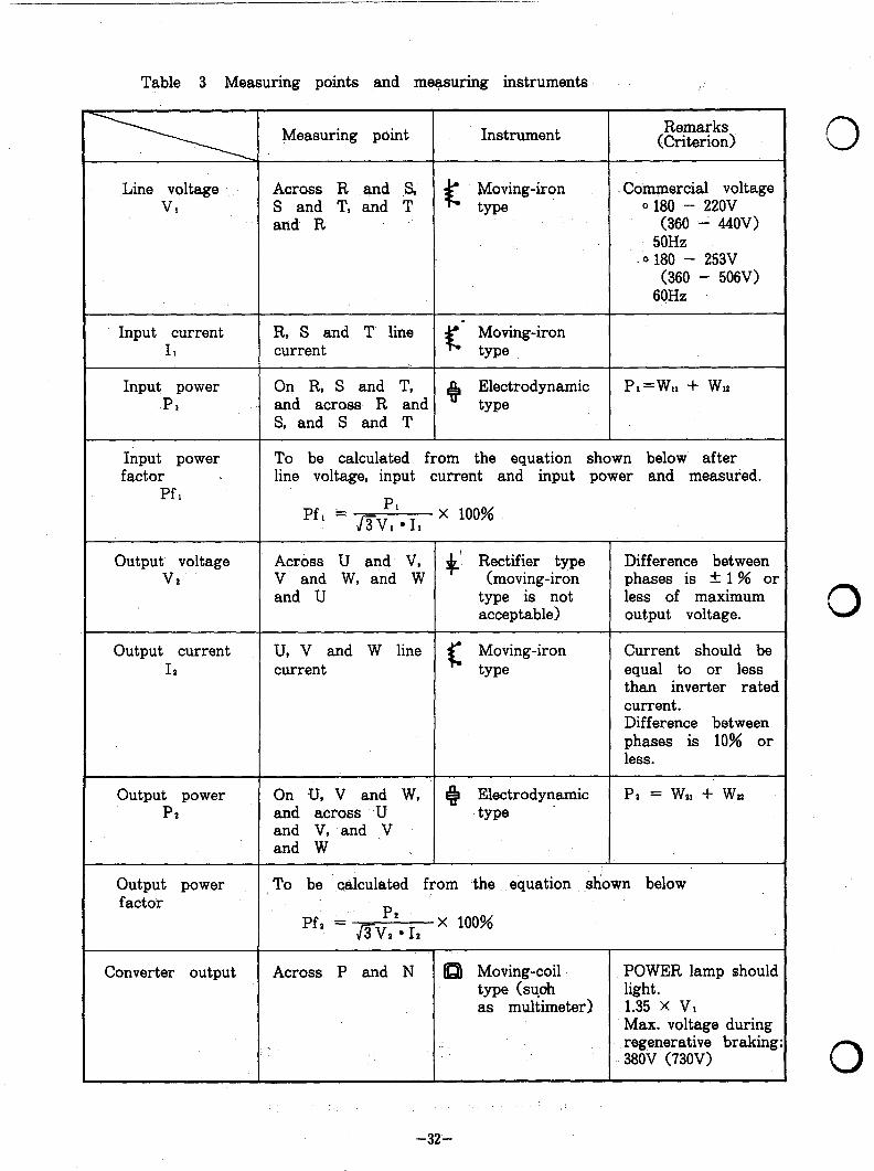
Table 3 Measuring points and measuring instruments
Measuring point Instrument Remarks (Criterion)
Line voltage VI
Across R and S, S and T, and T c
Moving-iron Commercial voltage type 0 180 - 22OV
and R (360 --i 44OV) 50Hz
0 180 - 253V (360 - 506V)
60Hz
Input current 11
Input power P*
R, S and T line - Moving-iron current c type
On R, S and T, 8
Electrodynamic P*=W,, + WI? and across R and type S, and S and T
Input power To be calculated from the equation shown below. after factor . line voltage, input current and input power and measured.
Pf, Pf, = &P1* I, X 100%
I Output voltage Across U and V, t ’ Rectifier type Difference between
VZ V and W, and W (moving-iron phases is * 1% or and U type is not less of maximum
acceptable) output voltage.
Output current U, V and W line c
Moving-iron Current should be I* current type equal to or less
than inverter rated current. Difference between phases is 10% or less.
Output power PZ
Pz = wn + wtr On .U, V and W, e Electrodynamic and across U type . and V, and ,V and W
Output power factor
: To be calculated from the equation shown below
Pf, = &IZ. I* X 100%
Converter output Across P and N a Moving-coil POWER lamp should type (suoh as multimeter)
light. 1.35 X VI Max. voltage during regenerative braking 380v (73OV)
-32-
0
0
0
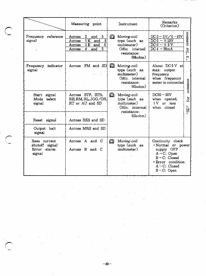
r -
Measuring point Instrument Remarks (Criterion)
Frequency reference Across 2 and 5 _ n Moving-coil DC O.- 5V/O -lOV G E signal Across 1 K and 5. type (such as ,DCO -klOV E
Across 1 E and 5 multimeter) DC0 -+5v 8 Across 4 and 5 (Min. internal DC 4 - 20mA 5
resistance: : 5Okohm) m
:
Frequency indicator Across FM and SD D Moving-coil About DC5V at signal type (such as max. output
multimeter) frequency (Min. internal when frequency resistance: meter is connected 5
50kohm) g 8
Start signal Across STF, STR, @), Moving-coil DC20 - 30V Mode select RH, RM, RL, JOG/OH, type (such as when opened, k signal RT or AU and SD multimeter) 1 V or less cy
(Min: intermal when closed resistance: b
50kohm) 1
Reset signal Across RES and SD
Output halt signal
Across MRS and SD
Base current shutoff signal Error alarm signal
Across A and C @) Moving-coil Continuity check type (such as ~Normal or power
Across B and C multimeter) supply OFF A-C: Open B - C: Closed
0 Error condition A - C: Closed B-C: Open
f- -
-33-
6.4 Mesuring instrument selection and usage
To observe the condition of insulation, voltage, current, signal level, waveform, 0 etc., select an adequate instrument and use it in accordance with the
following description:
(1) Measurements on main circuit
The measurements include power supply and output voltages and
current measurements, load (motor) continuity check, insulation check,
voltage and current waveform observation.
The followings are particularly important to be checked carefully with
the specified instrument(s):
0 Multfmeter
For continuity check with a multimeter, be careful of sneak path
circuit. Do not make continuity check for the inverter circuit transistor
module with the motor connected, and for the converter circuit diode
module with the power connected. 0 Make continuity check only for components to be checked with the
wiring to other components disconnected.
@ Voltmeter and ammeter
The input power supply voltage is sine-wave of the commercial
frequency. To measure the input voltage, any appropriate instrument
may be used.
Since the input and output current waveforms include various high-
harmonic components, use a moving-iron type ammeter, as it indicates
values in r.m.s., to measure the input and output currents.
To measure the output voltage, use a rectifier type voltmeter because
it reads nearly the basic wave component of the voltage waveform
which is used as the reference value of torque generated by the motor. 0

-_l__l___- I I . . - . . - - - “ . - - “ ” ._..* - - . . - . . . . ._, , . , . . ,_ . , , , . I . . .+
Anyway, it is important’ to record the instruments used and measurement
results, and to always use the same instruments at inspection.
0 Oscilloscope
To measure high voltage (4OOV or higher) , insulate the power supply
of oscilloscope and use a high-voltage probe or insulate the point to
be measured with a potential transformer or current transformer.
In the latter case, the potential transformer or current transformer
should have a capacity large enough to prevent magnetic saturation.
(21 Measurements on control circuits
The measurements on control circuits include measurements of frequency
reference signal, inverter control voltage and observation of waveforms.
For accurate measurement, note the followings:
@ Voltage measurement and waveform observation
Since the currents of these signals are faint and the impedances of
the circuits are high, use an instrument, input resistance of which is
as high as possible (lOOkohm to 1 Megohm) .
It is recommended to use a digital multimeter or oscilloscope in the
measurements.
Since input resistance of multimeter set in a low range is significantly
low, value read by multimeter may be lower than the true value.
0 Common line connection
Connect the common terminal of instrument to an optimum point of
circuit (i.e. the common point nearest to the point measured) .
@ Instrument characteristics
f- “,-
For waveform observation, use’ an oscilloscope which has characteristics
that meet the waveform to be observed.
-35-
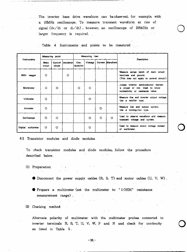
The inverter base drive waveform can be observed, for example, with,
a 10MHz oscilloscope. To measure transient waveform at rise of
signal (dv/dt or di/dt) , however, an oscilloscope of 200MHz or
larger frequency is required. ._
Table 4 Instruments and points to be measured
Measuring point Measuring item Instruments Description
.. Main Control insulation Con- Voltage Current W aveform circuit circuit ductivity
5ooV megger
Multimeter
0
0 0
0
t
0 0
Measure across batch of main circuit terminals and ground. (This does not apply to control circuit.)
Judges whether semiconductor element is proper or not. Used to know conductivity or resistance value.
Voltmster ? 0 Measure line and inverter output voltage. Use a rectifier type.
Ammeter 0 ‘0 Measure line and output current. Use a moving-iron type.
Oscilloscope 0 Used to observe waveform and measure
1 ’ 1 ’ 1 ’ 1 transient voltage and current.
Digital multimeter 0 0 0 Used to measure circuit voltage instead of multimeter.
6.5 Transistor modules and diode modules
To check transistor modules and diode modules, follow the procedure
described below.
(1) Preparation .
0 Disconnect the power supply cables (R, S, T) and motor ‘cables (II, V, W> .
l Prepare a multimeter (set the multimeter to “ 1 OHM” resistance
measurement range) .
(21 Checking method
Alternate polarity of multimeter with the multimeter probes connected to
inverter terminals R, S, T, U, V, W; P and N and check for continuity
as listed in Table 5.
0
0
0
-36.-
__~___.I.____----._-.lr--_ . - * , - . I , , . r b ( . , __,.._ -.~_l”ll_l-._----
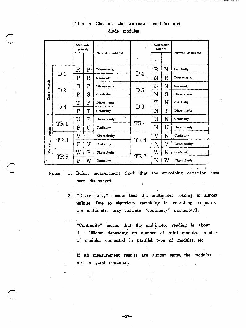
Table 5 Checking the transistor modules and
diode modules
Normal conditidns Normal conditions
Notes: 1. Before measurement, check that the smoothing capacitor have
been discharged.
2. “Discontinuity” means that the multimeter reading is almost
infinite. Due to electricity remaining in smqothing capacitor,
the multimeter may indicate “continuity” momentarily.
“Continuity” means that the multimeter reading is about
1 - lOOohm, depending on number of total modules, number
of modules connected in parallel, type of- modules, etc.
If all measurement results are almost same, the modules
are in good condition.
-37-
P
P TRl TR3 TR5
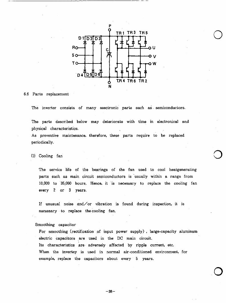
6.6 Parts replacement
Dim
id6 TR 2 N
0
v W
The inverter consists of many esectronic ,parts such as. semiconductors.
The parts described below may deteriorate with time in electronical and
physical characteristics.
As preventive maintenance, therefore, these parts require to be replaced
periodically.
(11 Cooling fan
The service life of the bearings of the fan used to cool heatgenerating
parts such as main circuit semiconductors is ‘usually within a range from
10,000 to 35,000 hours. Hence, it ‘is necessary to replace the cooling fan
every 2 or 3 years.
If unusual noise and/or vibration is found during inspection, it is
necessary to replace thecooling fan.
Smoothing capacitor
For smoothing (rectification .of input power supply) , large-capacity aluminum
electric capacitors are used in the DC main circuit.
Its characteristics are, adversely affected by ripple current, etc.
When the invertey is used in normal air-conditioned environment, for
example, replace the capacitors about every 5 years.
0
0

- ,_-. - . - . “ * - * , . , ._ < _ 4. . _. ._i .,_..___ ___I_-. I
When a capacitor is used for the period specified as life, it may
deteriorate suddenly.
It is necessary to check all smoothing capacitors yearly (several months
if life ‘is about to expire) .
. Check the followings:
0 Case . . Side walls and bottom for deformation
0 Sealing plate : For unusual warp and cracks
@ Pressure relief valve : For excessive valve expansion and
operation
@ Appearance, crack in case, discoloration and leakage: When capacitance of a capacitor is reduced below 85% of rated
capacitance, replace that capacitor. To measure capacitance, use an
instrument available commercially.
(3) Relays
To prevent miscontact, it is necessary to replace relays in accordance with the acumulated switching times.
For approximate interver parts replacement, refer to Table 6.
Other parts , having a relatively short service life, such as lamps. Replace
when deemed necessary as periodic inspection result will reveal.
Table 6 Inverter replacement parts
Part uame
Cooling fan
Smoothing capacitor 5 years Replace (determine after checking)
Relays Determine after checking
Standard interval 1 Description I
2 to 3 years Replace (determine after checking)
-39-

Q 7. TROIJBLESHOOTING
If a fault occurs and the mverter does not work properly,, determine the
cause referring to the following troubleshooting list and apply the remedy.
If the cause cannot be determined in accordance with the list, the inverter
or its part(s) ,is likely to be defective.
For remedy of serious trouble or any inquiry, contact the nearest service
representative.
7.1 Troubleshooting
(1) Troubleshooting by indicator lamps’ of parameter unit
Indicator lamp. Possible cause Checkup Remedy
OVT: Overvoltage in DC Is ’ deceleration too Increase deceleration Regenerative output circuit fast? time (it should meet overvoltage (across terminals load GDP (WK*) **a shut off P and N) inertia) ‘. (deceleration time set improperly)
IPF: Instantaneous power Determine the cause Instantaneous failure of instantaneous power failure power failure.
FIN: Heatsinks are Is cooling fan Replace cooling fan Heatsink overheat overheated. stopped (for models
larger than 2.2K) ? Reduce. ambient temperature.
Is ambient temp- erature too high? . . . .
BE: ‘Brake transistor is Is brake operating Reduce load GD* Brake transistor, defective. duty proper? (WK’) . fault Reduce brake
‘operating duty.
OCl: Overcurrent Is acceleration too Prolong acceleration Acceleration ‘.- - ftist? --. : ,time.
overcurrent Is outptt short- circuited?
‘0
0
-4o-

r
Indicator lamp
oc2: Steady speed overcurrent
Possible cause Checkup Remedy
Overcurrent Is load changed Eliminate sudden suddenly?, load change, Is output short- circuited?
oc3: Deceleration overcurrent
Is deceleration too Prolong deceleratior fast? time. Is output short- circuited?
THM: Overload alarm
Motor. thermal relay Is motor overloaded? Lighten load. Change motor/ inverter capacity.
THT: Inverter thermal relay Overload alarm
OLT: Stall prevention
UVT: Under voltage
Long-lasting action Is motor overloaded? Lighten load. of stall preventive Change motor/ function inverter capacity.
Low power supply Is a motor having Check power supply voltage a large capacity line.
(connected in the, same power line) started?
GF: Ground fault overcurrent
Ground fault in output line
Is output line or Check output line motor short-circuited and motor, and to ground? remove short-
circuiting.
OHT: Thermal relay provided Does motor Lighten load or External thermal in external circuit is overheat? duty. relay trip activated.
OPT: Option unit is not Is connector engaged Securely engage Built-in option connected to inverter securely. connector. unit connection properly. failure
If an indicator lamp lights, the motor stops after coasting. To resume motor operation, remove the cause, reset the protective function and restart the inverter.
‘
,.. . r‘
-41-
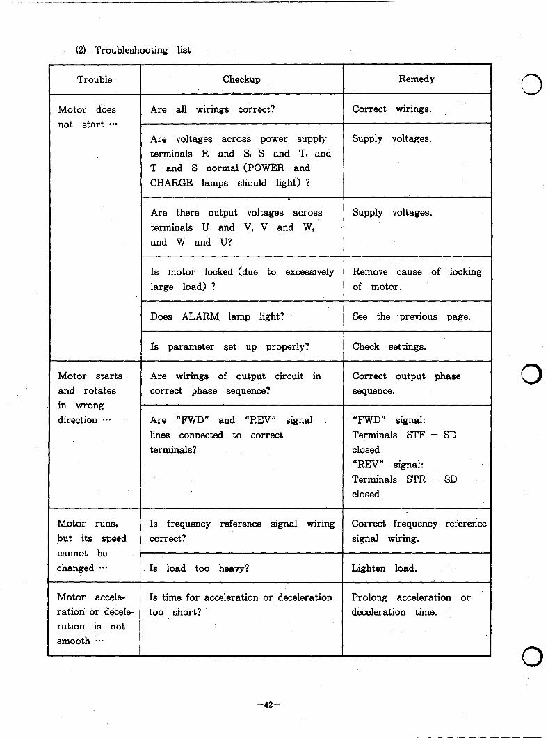
(2) Troubleshooting list
Trouble
Motor does not start ***
Motor starts and rotates in wrong direction a*.
Motor runs, but its speed
cannot be changed ***
Motor accele- ration or decele- ration is not smooth a**
Checkup
Are all wirings correct?
Are voltages across power supply terminals R and S, S and T, and T and S normal (POWER and CHARGE lamps should light) ?
.
Are there output voltages across terminals U and V, V and W, and W and U?
Is motor locked (due to excessively large load) ?
Does ALARM lamp light? *
Is parameter set up properly?
Are wirings of output circuit in correct phase sequence?
Are “FWD” and “REV” signal .
lines connected to correct terminals?
Is frequency reference signai wiring
correct?
Is load too heavy?
Is time for acceleration or deceleration too short?
Remedy
Correct wirings.
Supply voltages.
Supply voltages.
Remove cause of locking
of motor.
See the previous page.
Check settings.
Correct output phase sequence.
“FWD” signal:
Terminals STF - SD closed “REV” signal: Terminals STR - SD closed
Correct frequency reference signal wiring.
Lighten load.
Prolong acceleration or deceleration time.
0
0
0
-42-

. -.e . . d._ __-,- .---. .--I-- “ll__ ,. .I.. e... - 1. * .-. - .---
Trouble Checkup Remedy
Motor speed is Are number of poles of motor Check specifications and out of control correct? Does voltage meet Rating Plate.
(motor speed specifications? is too high
or low) . . . . . . Is gear reduction ratio correct?
Is maximum frequency set properly? Check maximum frequency
setting.
Are voltages across motor terminals Check base frequency
correct? (V/F) .
Motor speed is Is load too large? Lighten load. unstable *..
Is load change excessive? Minimize load change.
Increase inverter and motor capacities.
-43-

7.2’ Protective functions . .
The inverter is provided with the following protective functions for protection
from overcurrent or overvoltage.
If a protective function is activated, the transistor base current (output)
is shut off and the motor stops after coasting. Its cause is displayed by
the readout of parameter unit (when parameter unit is used) .
For details, refer to the description “PARAMETER UNIT”. (p. 92)
Function Description Remedy
Overcurrent When 150% (Note*) or more of the inverter Prolong acceleration
stall prevention . rated current flows into the motor during time or reduce load
acceleration, this function stops increase of to prevent recurrence
frequency (inverter output) until load current of action of this
reduces to prevent - the inverter from function.
overcurrent tripping.
When 150% or more of the inverter rated
current flows during normal (constant-
speed) operation, this function reduces
frequency until load current reduces to
prevent inverter from overcurrent tripping.
After load current is reduced below 150%,
this function allows increase of frequency
up to the preset frequency.
Regenerative If converter output voltage is increased Prolong deceleration
overvoltage excessively by regenerative energy during time.
stall prevention motor deceleration, this function stops
decrease of frequency to prevent inverter
from overvoltage tripping.
0
0
-44-
- . _ . . . . . . - - . , . . . . . . ^.l_l-- -,__,__-. _1 , - - , - , , , , , . - - . + . - ” .i< _ . . . * ._._” _-____
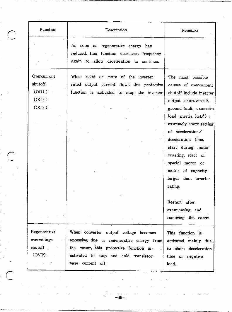
Function Description
As soon as regenerative energy has
reduced, this function decreases frequency
again to allow deceleration to continue.
Remarks
Overcurrent
shutoff
(OCl)
(OC2)
(OC3)
When 200% or more of the inverter The most possible
rated output current flows, this protective causes of overcurrent
function is activated to stop the inverter. shutoff include invertel
output short-circuit,
ground fault, excessivt
load inertia (GD’) ,
extremely short setting
of acceleration/
deceleration time,
start during motor
coasting, start of
special motor or
motor of capacity
larger than inverter
rating.
Restart after
examinating and
removing the cause.
Regenerative
overvoltage
shutoff :
(OVT)
When converter output voltage becomes This function is
excessive, ‘due to regenerative energy from activated mainly due
the motor, this protective function is to short deceleration
activated to stop and hold transistor time or negative
base current off. load.
-ai-
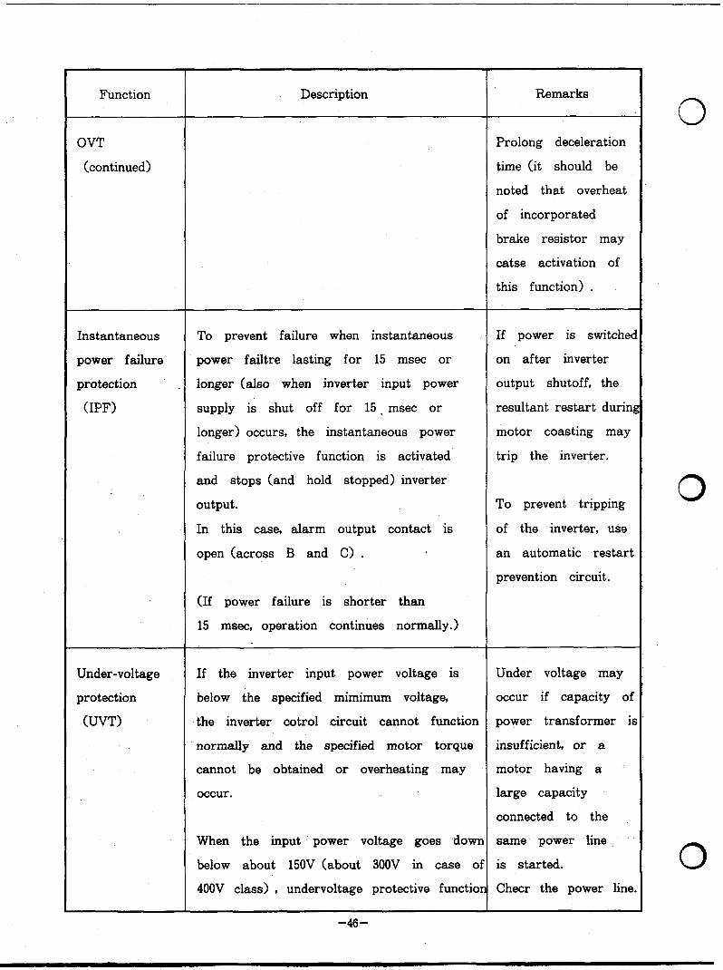
Function Description Remarks
OVT Prolong deceleration
(continued) time (it should be
noted that overheat
of incorporated
brake resistor may
catse activation of
this function) .
Instantaneous To prevent failure when instantaneous If power is switchec
power failure power failtre lasting for 15 msec or on after inverter
protection . longer (also when inverter input power output shutoff, the
(IPF) supply is shut off for 15 . msec or resultant restart durini
longer) occurs, the instantaneous power motor coasting may
failure protective function is activated trip the inverter.
and stops (and hold stopped) inverter
output. To prevent tripping
In this case, alarm output contact is of the inverter, use
open (across B and C> . an automatic restart
prevention circuit.
(If power failure is shorter than
15 msec, operation continues normally.)
Under-voltage If the inverter input power voltage is Under voltage may
protection below the specified mimimum voltage, occur if capacity of
(UVT) the inverter cotrol circuit cannot function power transformer ir
normally and the specified motor torque insufficient, or a
cannot be obtained or overheating may motor having a
occur. large capacity
connected to the
When the input ’ power voltage goes -down same power line
below about 150V (about 300V in case of is started.
400V class) , undervoltage protective function Cheer the power line
-46-

f-
r--
Function Description Remarks
is activated and stops (and holds stopped)
inverter output.
Brake transistor If trouble occurs with brake transistor,
fault detection this function detects it and shuts off
(BE) inverter output.
Examine thermal
capacity of brake
resistor and regene-
rative braking duty
(%ED) and use
inverter having a
larger capacity, if
necessary.
Overload shutoff Electronic thermal relay in the inverter Examine the cause
(Electronic detects overload of motor during operation of overload, and
thermal relay) under rated conditions, or motor over- lighten load, change
(THT) heating at low speed, and activates this operation pattern,
(THM) protective function which stops (holds or use inverter
stopped) inverter output. having a larger
capacity if necessary
CkUTION
External overload protection must be
provided to protect the motor in
accordance with UL508 Par.144.3.
Heatsink overheat Models larger than 2.2K are equipped
protection with cooling far&) .
(FIN) If the fan fails and the semiconductor
heatsinks overheat, temperature sensor is
activated to shut off (hold shut off)
inverter output.
Examine cooling fan
operation and ambient
temperature.

Function Description Remarks
Brake resistor If regenerative brake energy from motor Prolong deceleration
overheat exceeds the specified value, the brake time or change
protection operation is stopped to protect the operati-on sequence
brake resistor .from overheating. to reduce. braking
duty.
When the brake resistor is cooled, the
brake operation restarts automatically.
Ground fault If ground fault occurs on the inverter Check if ground
current protectior output side (load side) and ground fault fault occurs on the
(GF) _ current flows, the inverter output is load side (motor
shut off. power circuit) .
After removal of
the cause, restart
operation.
External thermal If externallyinstalled thermal relay for
relay trip protection of motor from overheat
(OHT) (or motor built-in thermal relay) is
activated (relay contact is opened) , the
inverter output is shut off and held
shut off.
This function is applicable when
Examine load and
motor duty to
determine the cause
of overheat.
,“external thermal signal input” function
is selected. (FUNCTION 46)
Built-in option When an inverter built-in option unit Check connection
unit connection is used and not connected properly (connector engage-
failure (misengagement of conector, for example) , men0 of option unit.
(OPT) the inverter is shut off. _’
0
0

- - “. ,..,.i-.“-- - - - ,-,- - - _-._._ .,. . .._- _..* .I.. _ , I _, .~ . . __.~l__l
Note *: The stall prevention threshold level is set to “150%” of
inverter rated current when the inverter is shipped. This
setting can be changed by user (the overcurrent stall
prevention is activated at the threshold level set by user) .
Use this function parameter with care.
INDICATION AND DISPLAY OF PROTECTIVE FUNCTION
If a protecsive function is activated,
0 ALARM lamp lights, and
0 Alarm information is dispkayed on the readout of parameter unit
(for details, refer to the description of “PARAMETER UNIT”) . (p. 92)
HOW TO RESET THE INVERTER
If a protective function is activated, the inverter output is shut off
(held shut off) and the -motor stops after coasting.
To resume operation, the inverter should be reset by turning off and
then on again, or short-circuit between RESET terminals (RES and SD>
for at least O.lsec.
If terminals (RES and SD) are held closed, “Err.” appears (flickering) in
the readout * of the parameter unit, indicating that the inverter is in a
reset condition. Do not switch on and off repeatedly by the mains unit.
HOW TO HOLD AN ALARM OUTPUT SIGNAL /
If the magnetic contactor on the power input side of the inverter is
opened when a protective function is actuated, the control circuit of
inverter is shut off from the power supply and the alarm signal cannot
be held on.
r
To hvld an alarm signal, an external circuit which holds an alarm signal
is used, or a separate power supply is provided for the control circuit
(refer to 4. WIRING, (5)) . ‘1
-4Q-

ALARM HISTORY
The alarm information is stored In the memory (E’ROM) of inverter, and 0 not erased even when the power is turned off.
Since a maximum of 4 alarms can be stored in the memory, they can
be read one by one to identify the cause (for details, refer to the
description’ of “PARAMETER UNIT”) . (p. 89)
0
0
-5o-
_x_ ,* ..*-_..- _IL_~~-_*--_--l-_II ,._-_ 1. . . ..^ .c -- ..-- --
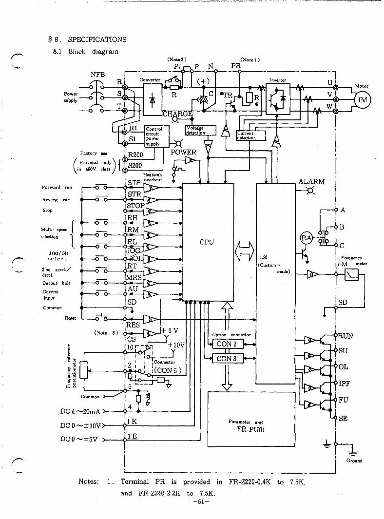
§ 8. SPECIFICATIONS
8.1 Block diagram (Note 2 ) (Note 1)
PR.
Factory use
Provided only in 400V class
ALARM i
-3
,
Forward run
Reverse run I I I ,I
stop
Multi- speed
selection
JOG/OH select
RA s CPU
G3 LSI
Custom - made) 2nd accel./
decel.
0 B.. t ATT
Output halt
(Note 3)
ii Jjg/y’
-J +1ov Y
:onnector
Current input
common
Reset
RUN
su
OL
IPF
FU
SE
Common dr
DC 4 -2OmA > 14 T -
DCOm+lOV> il K Y
Parameter unit
FR-PUOl DCOmk5V > ‘lE 1
i Ground
-- -I Notes: 1 . Terminal PR is provided in FR-Z220-0.4K to 7.5K,
and FR-Z24+2.2K to 7.5K. -51-

2. Terminal P 1 is provided in FR-Z220-5.5K to 55K, and
FR-Z240-5.5K to 55K.
3. Terminal CS is provided in models larger than FR-Z220-15K
and FR-Z240-11K.
*4 . For models larger than llK, built-in regenerative brake resistor
and brake transistor are not installed in the inverter. Fit
” BU ” brake option externally. on these larger models.
See page 53. P, P 1, PR, N.
0
0
0
-52-

. .- __,....-_ .___ j. ,. _I” .-... c.“---....” __,-.-”
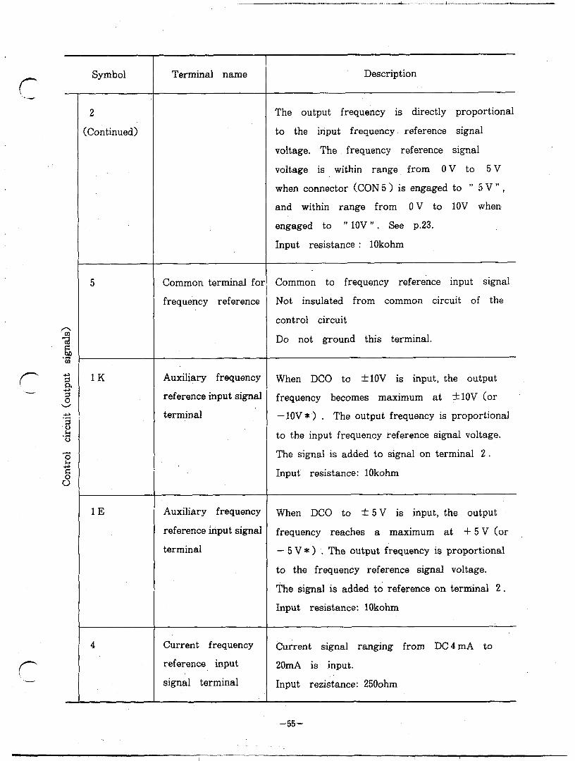
8.2 Terminals
Symbol
STF L STR
STOP
RH,RM,RL
JOG/OH
Terminal name
AC power supply input terminals
Inverter output terminals
Converter output terminals
Control power supply terminals
Ground terminal
Forward start input signal terminal
Reverse start input signal terminal
Start signal self- hold terminal
Multi-speed select terminals
JOG mode select or external thermal
Description
Connected to commercial power supply
Connected to three-phase squirrel-cage motor
Connected to optional BU type brake unit (terminals P and N) or external regenerative brake resistor (terminals P and PR)
Connected to power supply terminals (R and S) in the inverter. When it is desirous to hold alarm display, remove jumper wire from terminals R and S and connect external power supply to these terminals.
Inverter chassis grounding terminals
Motor starts rotating in forward direction (normal run) when ,STF and SD are short-circuited.
Motor starts rotating in reverse direction when STR and SD are short-circuited.
Start signal can be self-held ,when STOP and SD are short-circuited. (p. 13)
A speed range can be selected from 7 different preset speed ranges. (p. 103)
JOG operation mode is selected when JOG and SD are short-circuited. To start and stop in JOG, use. signals STF and SIR. (p. 106)
-53-

Symbol
JOG/OH Continued)
RT
MRS
RES
AU
SD
10
2
Terminal name
2 nd acceleration/ 2 nd acceleration/deceleration time can be
deceleration time selected by short-circuiting, between RT and select terminal SD.
Inverter output shutoff, input
terminal
Reset signal, input terminal
Current frequency
reference signal select terminal
Instantaneous stop,
restart select terminal
Common terminal .foi
contact input
Power supply terminal for
frequency reference
Frequency reference input signal
Description
With external relay, it is possible to stop inverter operation by a thermal contact input signal.
0
Shuts off transistor base current (inverter
output) to stop motor by. means of
magnetic brake, etc. Inverter output is shut off when MRS and SD are short-circuited.
To reset inverter after tripping, RES and SD are* short-circuited for ‘more than O.lsec,
When AU and SD are short-circuited, DC current ranging from 4 mA to 20mA can be used as frequency reference signal. 0 When CS and SD are held short-circuited, operation is restarted automatically after
restoration following a power failure. (p. 12)
Common to contact input signal and frequency indication Insulated from common’ circuit of inverter control circuit
DC 5 V or DClOV (selestabble by changing
position of connector) . See p. 23. Permissible maximum load current: 1OmA
When 0 to 5 V signal ‘(or 0 to lOV> is input, the output frequency is at a maximum at 5 V (or lOV> of input voltage.
0
-54-
..-...--- .s .I .-,-A.. .-. .- .-.. “.A..” “_. . ..,&.--
If- 1/ - -‘w
r -a.-.-
Symbol
2
IContinued)
5
.K
1E
4
Terminal name
Common terminal fol
frequency reference
Auxiliary frequency
reference input signal
terminal
Auxiliary frequency
reference input signal
terminal
Current frequency
reference input
signal terminal
Description
The output frequency is directly proportional
to the input frequency reference signal
voltage. The frequency reference signal
voltage is within range from ov to 5v
when connector (CON 5 > is engaged to m 5 V “,
and within range from 0 V to 1OV when
engaged to ” 1ov ” . See p.23.
Input resistance : 1Okohm
Common to frequency reference input signal
Not insulated from common circuit of the
control circuit
Do not ground this terminal.
When DC0 to +lOV is input, the output
frequency becomes maximum at +lOV (or
-lOV*) . The output frequency is proportional
to the input frequency reference signal voltage.
The signal is added to signal on terminal 2.
Input resistance: 1Okohm
When DC0 to + 5 V is input, the output
frequency reaches a maximum at + 5 V (or
- 5 V * > . The output frequency is proportional
to the frequency reference signal voltage.
The signal is added to reference on terminal 2.
Input resistance: 1Okohm
Current signal ranging from DC4 mA to
20mA is input.
Input rezistance: 2500hm
-55-
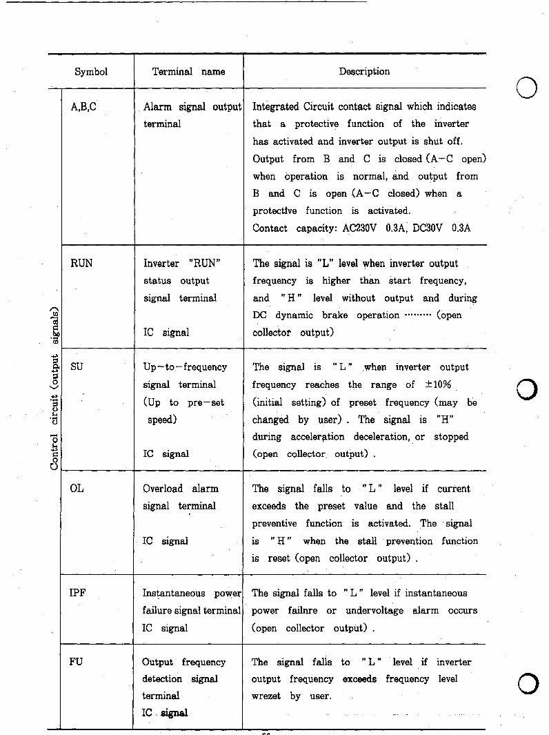
Symbol Terminal name
A,W
RUN
IPF
FU
Alarm signal outpui
terminal
Inverter “RUN”
status output
signal terminal
IC signal
Up-to-frequency
signal terminal
(Up to pre-set
speed)
IC signal
Overload alarm
signal terminal
IC signal
Instantaneous power
failure signal terminal
IC signal
Output frequency
detection signal
terminal
IC ,~ signal
Description
0 Integrated Circuit contact signal which indicates
that a protective function of the inverter
has activated and inverter output is shut off.
Output from B and C is closed (A-C open)
when operation is normal, and output from
B and C is open (A-C closed) when a
protectfve function is activated.
Contact capacity: AC230V 0.3A, DC3OV 0.3A
The signal is “L” level when invert.er output
frequency is higher than start frequency,
and ” H ” level without output and during
DC dynamic brake operation ********. (open
collector output) :
The signal is ” L ” when inverter output
frequency reaches the range of -tlO%
(initial setting) of preset frequency (may be
changed by user) . The signal is “H”
during acceleration deceleration, or stopped
(open collector, output) .
The signal falls to ” L ” level if current
exceeds the preset value and the stall
preventive function is activated. The signal
is ” H ” when the stall prevention function
is reset (open collector output) .
The signal falls to ” L ” level if instantaneous
power failnre or undervoltage alarm occurs
(open collector output) .
The signal falls to ” L ” level if inverter
output frequency exceeds frequency level
wrezet by user. 0
-56-
r -
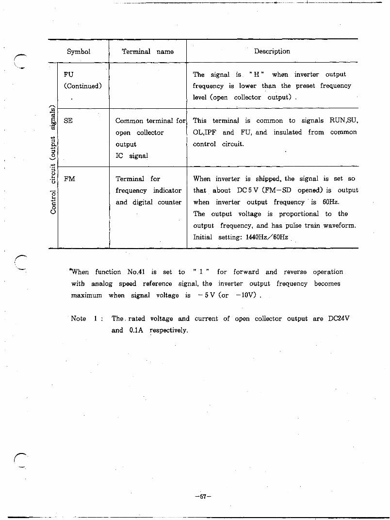
Symbol
FU
(Continued)
SE
FM
Terminal name
Common terminal for
open collector
output
IC signal
Terminal for
frequency indicator
and digital counter
Description
The signal is ” H ” when inverter output
frequency is lower than the preset frequency
level (open collector output) .
This terminal is common to signals RUN,SU,
OLJPF and FU, and insulated from common
control circuit.
When inverter is shipped, the signal is set so
that about DC 5 V (FM-SD opened) is output
when inverter output frequency is 60Hz.
The output voltage is proportional to the
output frequency, and has pulse train waveform.
Initial setting: 1440Hz/60Hz
*When function No.41 is set to ” 1 ” for forward and reverse operation
with analog speed reference signal, the inverter output frequency becomes
maximum when signal voltage is - 5 V (or -lOV> .
Note 1 : The. rated voltage and current of open collector output are DC24V
and O.lA respectively.
f
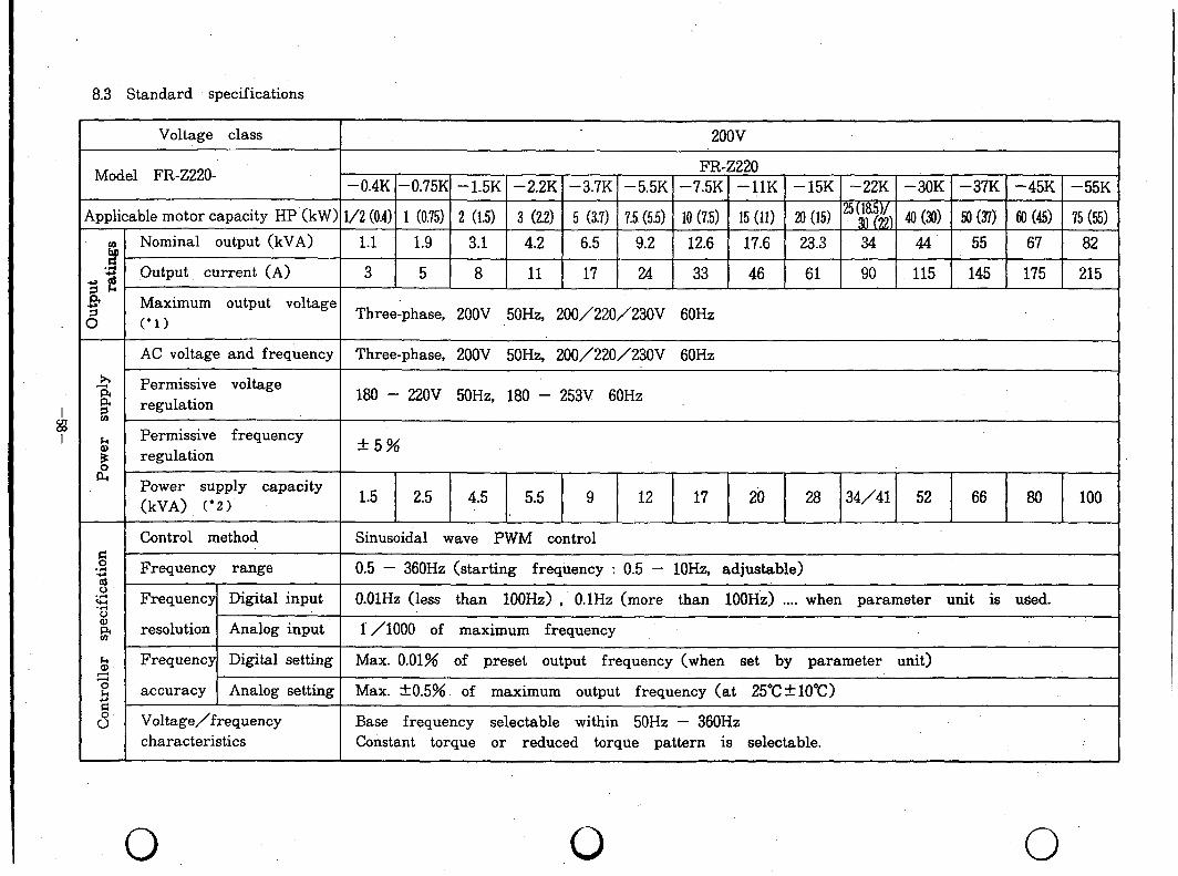
8.3 Standard specifications
Voltage class 2oov
Model FR-ZZZO- FR-Z220
-0.4K -0.75K -1.5K -2.2K -3.7K -5.5K -7.5K -1lK -15K -22K -3OK -37K -45K -55K
ipplicable motor capacity HP (kW) i/2 (0.4) 1 (0.75) 2 (1.5) 3 (2.2) 5 (3.7) 7.5 (5.5) 10 (7:5) 15 (11) 20 (15) ‘($t$ 40 (30) 50 (371 60 (45) 75 (55)
0 Nominal output (kVA) i?
1.1 1.9 3.1 4.2 6.5 9.2 12.6 17.6 23.3 34 44 55 67 82
,.d Output, current (A) *w 3 5 8 11 17 24 33 46 61 90 115 145 175 215 Sk 9 8
Maximum output voltage C.1)
Three:phase, 2OOV 50H2, 200/220/23OV 60Hz
AC voltage and frequency Three-phase, 2OOV 50H2, 200/220/23OV 60Hz
4
$
Permissive voltage regulation 180 - 22OV 5OH2, 180 253V 60Hz -
cn .
k Permissive frequency regulation
+5% B fc
Power swdy capacity (kVA) (‘2) 1 5 2 5 4 5 5 5 g 12 17 2b 28 34/41 52 66 80 100
Control method Sinusoidal wave PWM control
Ei 5 Frequency range 0.5 - 360Hz (starting frequency : 0.5 - lOHz, adjustable) d 0 5 Frequency Digital input O.OlHz (less than 100Hz) , O.lHz (more than lOOH&) . . . . when parameter unit is used.
ii ,a resolution Analog input I /lOOO of maximum frequency
ii Frequency Digital setting Max. 0.01% of preset output frequency (when set by parameter unit) 2 E z
accuracy Analog setting Max. *0.5% of maximum output frequency (at 25“C+lO”C)
s Voltage/frequency Base frequency selectable within 50Hz - 360Hz characteristics Constant torque or reduced torque pattern is selectable.
0 0 0
i ‘)
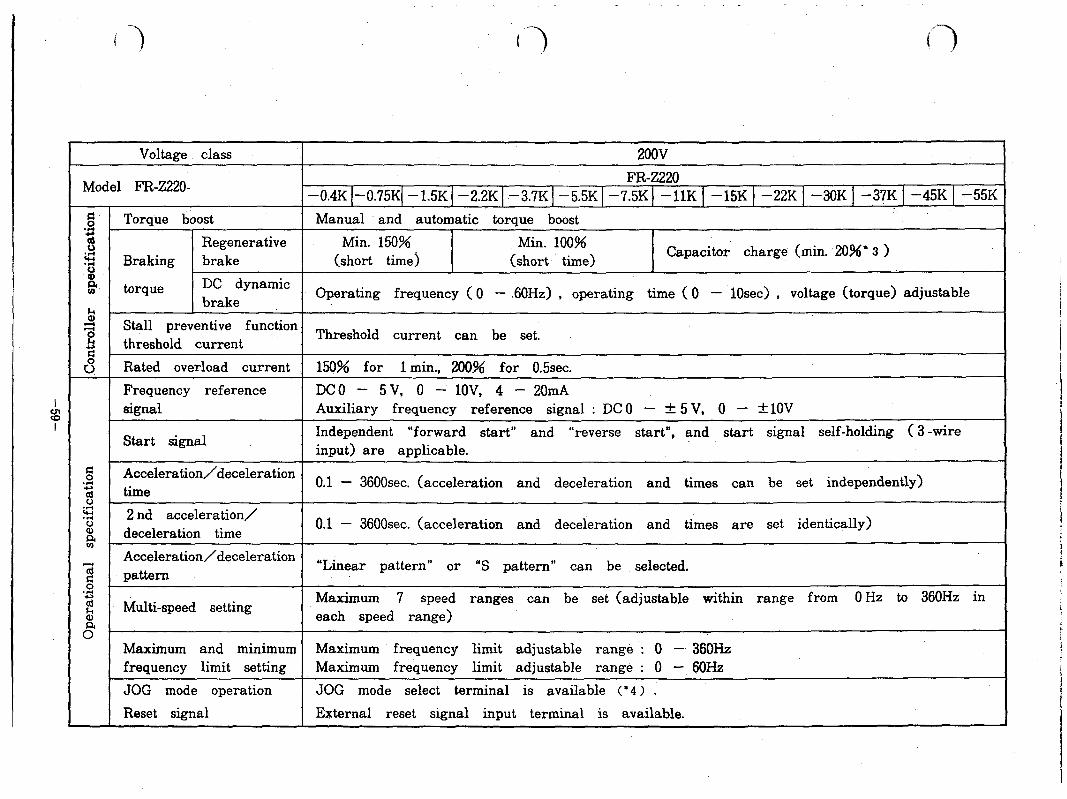
Voltage class 2oov
Model FR-2220- FR-Z220
-0.4K I-0.75KI -1.5KI -2.2KI -3.7KI -5.5KI -7.5K) -1lK 1 -15K 1 -22K ) -3OK 1 -37K 1 -45K 1 -55K
g Torque boost Manual and automatic torque boost 3 8 Regenerative Min. 150% Min. 100% 5 Braking brake 0 (short time) (short time)
Capacitor charge (min. 20%’ 3 )
;, torque DC dynamic brake
Operating frequency ( 0 - ,60Hz) , operating time ( 0 - 10sec) , voltage (torque) adjustable
!s i=i E:
Stall preventive function
2 threshold current
Threshold current can be set.
s Rated overload current, 150% for 1 min., 200% for 0.5sec.
Frequency reference DC0 - 5 V, 0 - lOV, 4 - 20mA signal Auxiliary frequency reference signal : DC 0 - + 5 V, 0 - &lOV
Start signal Independent “forward start” and “reverse start”, and start signal self-holding ( 3 -wire input) are applicable.
E’ Acceleration/deceleration ‘S time
o 1 . - 3600sec. (acceleration and deceleration and times can be set independently)
$ . r;t ‘i; 2 nd acceleration/ a deceleration time
0.1 - 3600sec. (acceleration and deceleration and times are set identically) iit
Acceleration/deceleration T;;i pattern
“Linear pattern” or “S pattern” can be selected. g ‘3 2 Multi-speed setting
Maximum 7 speed ranges can be set (adjustable within range from 0 Hz to 360Hz in
% each speed range) 0
Maximum and minimum Maximum frequency limit adjustable range : 0 - 36OHz frequency limit setting Maximum frequency limit adjustable range : 0 - 60Hz
JOG mode operation JOG mode select terminal is available (‘4 ‘1 .
Reset signal External reset signal input terminal is available.

I 8 I
Voltage class 200v
Model FR-Z220- FR-Z220
-0.4K (-0.75KI -1.SK I-2.2K I-3.7K 1 -5.5K 1 -7.5K 1 -1lK 1 -15K 1 -22K 1 -3OK 1 -37K 1 -45K 1 -55K
3 Output halt signal Output halt input signal termial is available.
‘2 Operation status output Sk
‘RUN”, “SU” (up-to-frequency) , “ON” (overload) , “IPF” (instantaneous power failure) and
9 signals “FU” (frequency detection) signals
3 Alarm output signal 1 C relay contact signal (AC 230V 0.3A, DC 30V 0.3A)
Protective, alarm and warnin Overcurrent shutoff (during acceleration, deceleration and normal operation) , regenerative functions overvoltage shutoff, undervoltage protection, instantaneous power failure protection, overload
shutoff, (electronic terminal relay) , brake transistor fault detection (‘5 > , ground overcurrent ‘. protection, output short-circuit protection, heatsink overheat protection 0 6 > , brake regenerative resistor overheat protection (+5 >’ , stall prevention and overload alarm
Ambient temperature -10°C to +5O“C (to be free from freezing)
% Ambient humidity 2
9O%RH or less (to be free from condensation)
E Storage temperature (’ 7 > 1 -20°C to +65”C
‘5’ . Atmosphere Indoor To be free from corrosive gases and. dense dust
3 Altitude, vibration Below 10OOm (3300ft) 4
0.6G or less (conforms to JIS 0911)
Built-in optional units Maximum 2 cards. can be used.
Protective structure (JEM 1030)
Enclosed type (IP20) Open type (wx>)
Weight (kg) kg (Lb)
Notes : l 1. If the line voltage decreases, output voltage over the line v&age cannot be guaranteed. l 2. Power supply capacity indicates the inverter input kVA and may change depending on power supply
impedance (including input reactor) . * 3. This value may’ depend on motor loss. * 4. JOG ,operation can be controlled not’ only with signal on JOG mode select terminal, but also parameter
unit. * 5. This function is not provided for models FR-Z2WllK to 55K, and FR-Z2QO-11K to 55K.
0 0 0

Voltage class 4OOV
Model FR-Z240- FR-Z240
-2.2K -3.7K -5.5K -7.5K -1lK - 15K -22K -3OK -37K -45K -55K
Applicable motor 3 (2.2) 5 (3.7) 7.5 (5.5) 10 (7.5) 15 (11) 20 (15) “$j5& 40 (30) 50 (37) 60 (45) 75 (55)
capacity HP (kW)
G Nominal output (kVA) 4.2 6.9 . 9.9 13 17.5 23.6 32.8 43.4 54 65.5 84
5 2. -2 Output current (A) 6 9 13 17 23 31 43 57 71 86 110
P Maximum output voltage (. 1) Three-phase, 400V 5OH2, 400/440/46OV 60Hz
6 AC voltage and frequency Three-phase, 400V 50Hz, 400/440/46OV 6OHz
x Permissive voltage 34 360 - 440V 50Hz, 360 - 506V 60Hz is
regulation
Permissive frequency +5% b
B regulation
62 Power supply capacity 5 5 (kVA) (* 2 > ’ 9 12 17 20 28 34/41 52 66 80 100
Control method Sinusoidal wave PWM control
2 Frequency range 0.5 - 360Hz (starting frequency: 0.5 - lOHz, adjustable)
22 2
Digital Frequency
O.OlHz (less than 100Hz) , O.lHz (more than 1OOHz) . . ..when parameter unit is used. 5
input
8 resolution Analog 2 input 1 /lOOO of maximum frequency
2 Digital =I’ Frequency Max. 0.01% of preset output frequency (when set by parameter unit) & setting 2 accuracy
Analog Max. +0.5% of maximum output frequency (at 25”C+lO”C) s
Voltage/frequency Base frequency selectable within 50Hz - 360Hz characteristics Constant torque or reduced torque pattern is selectable.
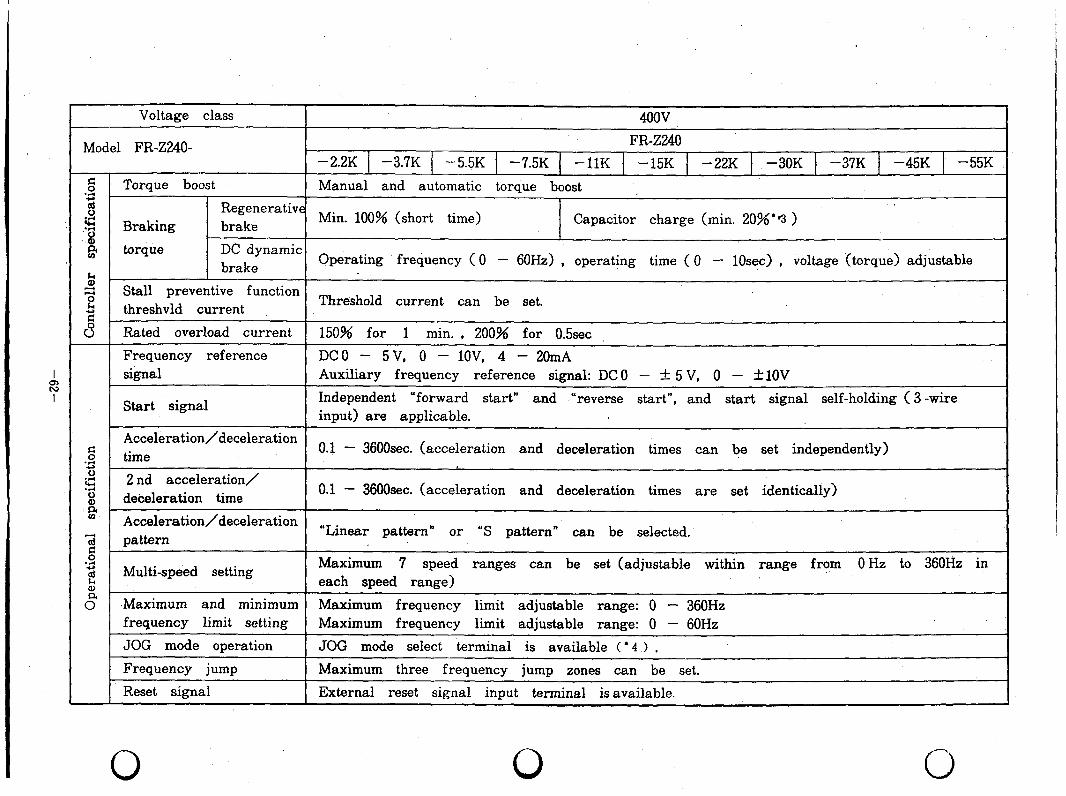
Voltage class 400v
Model FR-Z240- FR-Z240
-22K 1 -3.7K 1 -5.5K 1 -7.5K -1lK -15K -22K 1 -3OK 1 -37K 1 -45K 1 -55K
g Torque boost ‘I:
Manual and automatic torque boost ,
d Regenerative c .r( 8
Braking brake Min. 100% (short time) Capacitor charge (min. 20%*‘3 )
iit torque DC dynamic
!ii brake Operating frequency ( 0 - 60Hz) , operating time ( 0 - 1Osec) , voltage (torque) adjustable
z e
Stall preventive function threshvld current
Threshold current can be set. 2 u” Rated overload current 150% for 1 min. , 200% for 0.5sec
Frequency reference DC0 - 5 V, 0 - l.OV, 4 - 20mA signal Auxiliary frequency reference signal: DC 0 - & 5 V, 0 - &lOV
Start signal Independent “forward start” and .Yeverse start”, and start signal self-holding ( 3 -wire input) are applicable.
Acceleration/deceleration do
o I . - 36OOsec. (acceleration and deceleration times can be set independently)
3 time 0 5 2 nd acceleration/ 8 deceleration time
0.1 - 36OOsec. (acceleration and deceleration times are set identically)
ii? Acceleration/deceleration 74 od
pattern “Linear pattern” or “S pattern” can be selected.
‘S 2 Multi-speed setting
Maximum 7 speed ranges can be set (adjustable within range from 0 Hz to 360Hz in
Q) each speed range)
8 .Maximum and minimum Maximum frequency limit adjustable range: 0 - 360Hz frequency limit setting Maximum frequency limit adjustable range: 0 - 60Hz
JOG mode operation JOG mode select terminal is available ( l 4 > ,
Frequency jump Maximum three frequency jump zones can be set.
Reset signal External reset signal input terminal is available.
0 0 0
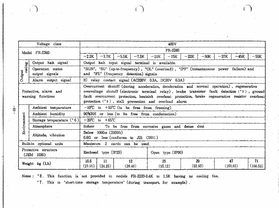
Voltage class 4oov
Model FR-Z240- FR-2240
-22K 1 -3.7K 1 -5.5K 1 -7.5K 1 -1lK -15K 1 -22K 1 -3OK 1 -37K ] -45K 1 -55K
2 Output halt signal Output halt input signal terminal is available.
5 .$ Operation status “RUN”, “SU” ‘(up-to-frequency) , ‘OL” (overload) , “IPF” (instantaneous power failure) and
i3 output signals and “FU” (frequency detection) signals
a Alarm output signal IC relay contact signal (AC230V 0.3A, DC30V 0&3A)
Overcurrent shutoff (during acceleration,’ deceleration and normal operation) , regenerative Protective, alarm and overvoltage shutoff (electronic terminal relay) , brake transistor fault detection (* 5 > , groun warning functions fault overcurrent protection, heatsink overheat protection, brake regenerative resistor overhee
protection ( * 5 > , stall prevention and overload alarm
Ambient temparature -10°C to +5O”C (to be free from freezing)
2 Ambient humidity 9O%RH or less (to be free from condensation) ii! Storage temparature ( l 6 ) -20°C to +65”C 2
‘5’ Atmosphere Indoor To be free from corrosive gases and dense dust
I3 Altitude, vibration Below 1OOOm (3300ft) 0.6G or less (conforms to JIS CO911 >
Built-in optional units Maximum 2 cards can be used.
Protective structure (JEM 1030)
Enclosed type (IP20) Open type (IPOO)
Weight kg (Lb) 10.5 11 12 25 47 71
(23.15); '(24.25) (26.46) (55.12) (632993) (103.62) (156.53;
Notes : l 6. This function is ‘not provided in models FR-Z220-0.4K to 1.5K having no cooling fan.
’ 7. This is “short-time storage temperature” (during transport, for example) .

8.4 External dimensions
Dimension in mm 0 n FR-Z220-0.4K(P)-3.7K(P) [2OOV class]
n FR-Z220-5.5K(P)--1lK [2OOV class) \ FR-Z240y2.2K(P)--7.5K(P) [4OOV class)
------- r rt-- ----‘! I! : I
L j 1wit”
l 2QOV clan Inverter model C H
FR-Z220-O.IK(P) 110 50 FR-Z220-O.EK(P) 140 80 FR-Z220-1.5K(P) 140 80 FR-Z220-2.2K(P) 170 110 FR-Z220-3.7K(P) ,170 110
Note: &dels FR-Z220-0.4K to 1.5K are not equipped with cooling fan.
View from *rrow
l 2OOV class l 4WV class lnverter model lnverter model
PR-Z220-5.5K(P) 1%2220-7.5K(P) FR-Z220-1lK
FR-Z240-2.2K(P) FR-Z240-3.7K(P) FR-Z240-5.5K(P) FR-Z240-7.5K(P)
n FR-Z220-15K--55K 12OOV class1 , FR-Z240-11 K--55K [4OOV class]
0
l 2WV clase
l 4OOV class
0 K
-64-

8.5 Selection of peripheral devices
inverter model
Notes: 1 . The interrupting capacity of NFB (no-fuse breaker) should be selected in accordance with power supply capacity.
-65-
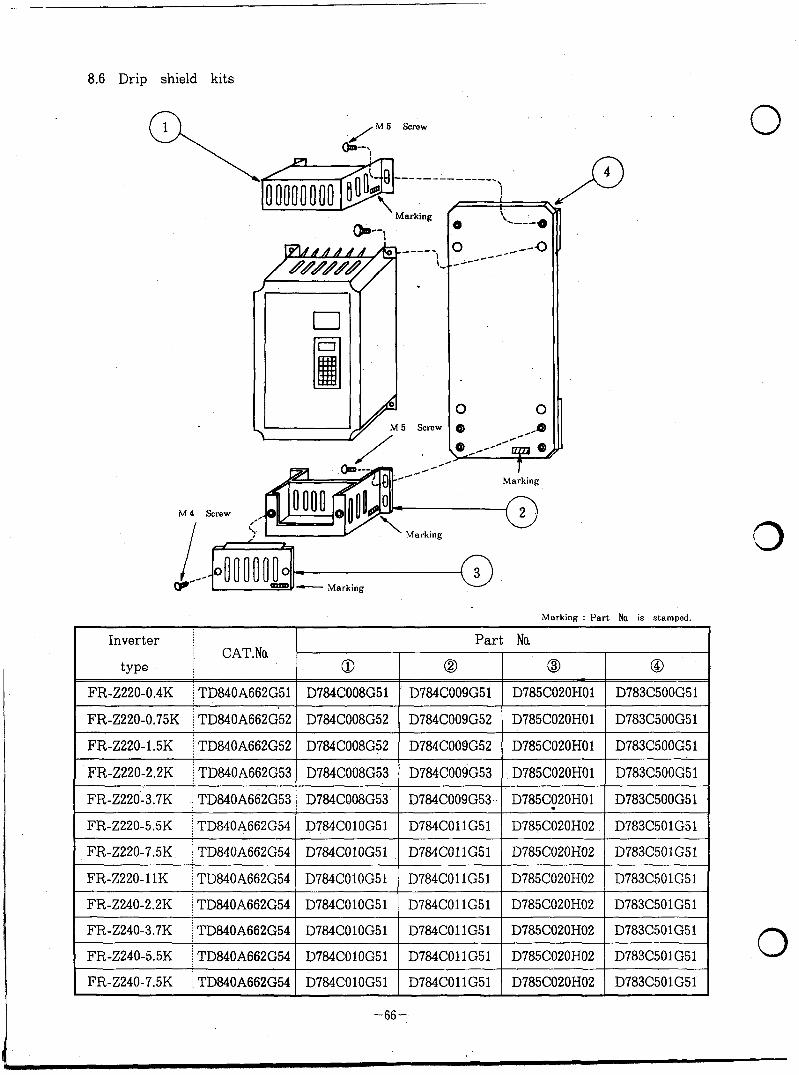
8.6 Drip shield kits
0 \@f&$$$---y--
Markmg
(P--i
Marking
0
Marking : Part Na is stamped.
FR-Z220-11K i TD840A662G54 D784COlOG51 D784COllG51 D785C020H02 D783C501G51
FR-Z240-2.2K 1 TD840A662G54 D784COlOG51 D784COllG51 D785C020H02 D783C501G51
FR-Z240-3.7K i TD840A662G54 D784COlOG51 D784COllG51 D785C020H02 D783C501G51
FR-2240-5.5K ) TD840A662G54 D784COlOG51 D784COllG51 D785C020H02 D783C501G51
FR-Z240-7.5K j TD840A662G54 D784COlOG51 D784COllG51 D785C020H02 D783C501G51
0
-66-

M 5 Scre !W
Marking
Marking
M4 screw
o-, 6 1 Marking
II -Marking
Marking : Part No. is stamped.
FR-Z220-37K TD84OA663G54 D714C569G53 D708C556HO3 D811C138HOl D714C569G58 D708C556HO7 lMlC138HO5 D811C138HO5
FR-Z220-45K TD84OA663G54 D714c569G53 D706CS56HO3 D311C138HO1 D714C569G58 D708C556H07 DEllC138HO5 D811Cl38HO5
E’R-Z220-55K TD84OA663G54 D714CS69G53 D708c556EfO3 D811C138HOl D714C569G58 MMS56H07 D811C138HO5 D811C138HO5
FR-Z24Q-1lK TlWOA663G52 D714cX69G52 D708c556HO2 iXllC138HOl D714CS69G55 D708CS56HO5 DSllC138HO3 D811C138HO4
FR-Z240-15K TD84OA663G52 D714CLi69G52 D708Ci56H02 D811C138HOl D714C569G55 D708c556HO5 D811C138HO3 lMlC138HO4
FR-2X40-22K TD84OA663G52 D714CS69G52 D7@3CX%HO2 D611C138HOl D714C569G55 D708cs56HO5 D811C138HO3 D811C138HO4
FR-Z24NOK TWA663G52 D714CS69G52 MWI556H02 D811C138HOl D714C569G55 D708C556H05 D811C138HO3 JXllC138Ho4
FR-Z240-37K TD84OA663G53 D714C569G53 D708CS56HO3 D811C138HOl D714CE69G56 MOW56H06 D811C138HO5 D811C138HO5
FR-Z240-45K TD84OA663G53 D714c569G53 D708cs56HO3 D811C138HOl D714C569G56 MW556HO6 D811C138HO5 D811C138HO5
FR-Z240-55K TD84OA663G53 D714C569G53 D708C556HO3 D811C138HOl D714C569G56 D708C556HO6 D811C138HO5 D811C138HO5
-67-
8.7 Overload protection
External overload protection must be provided to protect the motor in
accordance with the National Electrical Code.
0
Note: The drive is suitable for use on a circuit capable of delivering 10,000
RMS Symmetrical Amps.
0
-68-

1 PARAMETER UNIT 1
-69-
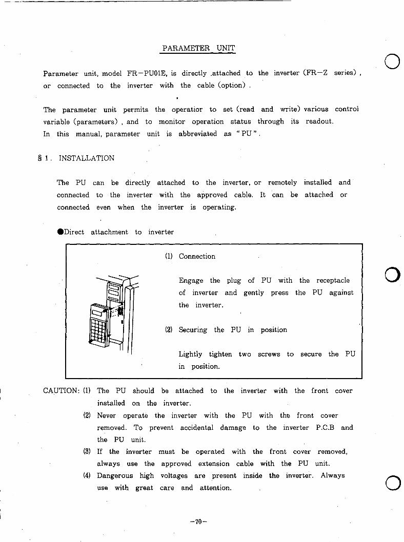
PARAMETER UNIT
Parameter unit, model FR-PUOlE, is directly .attached to the inverter (FR-Z series) , 0
or connected to the inverter with the cable (option) .
The parameter unit permits the operatior to set (read and write) various control
variable (parameters) , and to monitor operation status through its readout.
In this manual, parameter unit is abbreviated, as “ PU ” .
§ 1. INSTALLATION
The PU can be directly attached to the inverter, or remotely installed and
connected to the inverter with the approved cable. It ‘can be attached or
connected even when the inverter is operating.
l Direct attachment to inverter
(11 Connection
Engage the plug of PU with the receptacle
of inverter and gently press the PU against
the inverter.
(2) Securing the PU in position
Lightly tighten two screws to secure the PU
in position.
CAUTION: (11 The PU should be attached to the inverter with the front cover
installed on the inverter.
(2) Never operate the inverter with the PU with the front cover
removed. To prevent accidental damage to the inverter P.C.B and
the PU unit.
(3) If the inverter must be operated with the front cover removed,
always use the approved extension cable with the PU unit.
(41 Dangerous high voltages are present inside the inverter. Always
use with great care and attention.
-7o-
0
0

r. ‘- ORemote installation using the approved cable connector
(1) Connection
Plug one end of the cable into the
receptacle of inverter, and the other end
into the PU.
Locking of plugs
The plug on the inverter side should be
locked with screws as shown to the left.
On the PU side, secure the cable so that Fit the guides to the grooves.
the cable cannot be disconnected by its
own weight.
CAUTION: (1) For cable, use only that specified by us (available as optional
accessory) .
(2) The cable plugs and sockets only fit in one position. Do not
force plugs into sockets.
-71-

8 2. OUTLINE OF FUNCTIONS
Description
Selection of Parameter unit can b Keys of parameter
operation mode used as control sour unit are operated.
(Parameter mode) --_-------------------------
(External mode) be used as control
source for inverter
quency reference poten-
tiometer, START switch,
write) of control
variables
(Monitor/alter)
Set control variable
Change of setting
settings (settings made at shipment)
e parameter can
Operation status can
be monitored.
Direction of rotation
0.
-72-
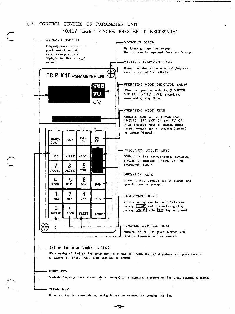
8 3. CONTROL DEVICES OF PARAMETER UNIT
“ONLY LIGHT FINGER PRESURE IS NECESSARY”
---DISPLAY (READOUT) 7MOUNTING SCREW
Frequency, motor current, preset control variable, alarm massage, etc. are displayed by this 4 -digit readout.
By loosening these two screws. the unit can be separated from the inverter.
VARIABLE INDICATOR LAMP r i“
Control variable to be monitored f _
f%-PUOl E PARAMETER UNli @ motor current. etc.) is indicated.
OPERATION MODE INDICATOR LAMPS
When an operation mode key (MONITOR, SET, EXT OP. PU OP) is pressed. the corresponding lamp lights.
I.
1
OPERATION MODE KEYS
Operation mode can be selected from MONI’I’OH. WI’, EXT OP and PU OP. Afler operation mode is selected. desired control variable can bc set, read (checked) or written (changed)
I
FliEQUI%‘CY ADJUST KEYS
While it is held down, frequency continously increases or decreases. (Slowly at first, progressively faster)
HIGH r OPERATION KEYS
Motor rotating direction can be selected and operation can be stopped.
-READ/WRITE KEYS
I? . . I \I I
1-1 I T I 1 I
\! I Variable setting can be read (checked) by pmssing ml and written (changed) by pressing [WRITE( after m key is pressed.
.FUNCTION/NUMERAL KEYS
d I Function No. of 1 st group function and 1 - I value or frequency can be specified.
- 2nd or 3rd group function key (2 nd)
When setting of 2nd or 3 rd qroup function is read or written, this key is pressed. 3 rd group function is selwted by SHIFT KEY after this key is pressed.
- SHIFT KEY
Variable (frequency, motor current, alarm message) to be monitored is shifted or 3rd group function is selected.
- CLEAR KEY
If wrong key is pressed during setting, it can be cancelled by pressing this key.
-73-

Key Description
pzE?q This key is pressed when external signals are used to control the inverter. (Inverter always powers up in this mode)
This key is pressed when the PU (parameter unit) is used to control the inverter.
I SET This key is pressed to read (check) or write (change) setting of variable.
IMONITOR This key is pressed to read frequency, motor current, output v,oltage or alarm message (alarm code) .
0, 2nd 2 nd or 3 rd group function can be selected.
piiiiiq This key is pressed to change variable to be monitored, to select 3 rd group function, or to specify JOG mode.
This key is pressed to correct wrong ‘key operation, or erase previous entry.
tl A
During operation with the PU, this key is pressed to increase output frequency.
During operation with external signals, this key is pressed to increase reading of externally connected frequency meter. (Calibration mode)
q v .During operation with the PU, this key is pressed to decrease output frequency.’
During operation with external signals, this key is pressed to decrease reading of externally connected frequency meter. (Calibration mode)
I FWD During operation with the PU, this key is pressed to make the motor rotate in normal direcion.
El REV
lsTop[
During operation with the PU, this key is pressed to make the motor rotate in opposite direction.
During operation with the PU, this key is pressed to stop the motor.
pfiiFq This key is pressed to change setting of frequency or other control variable.
~
ml ” l ” is used to specify decimal point.
This key is pressed to check setting of variable.
0
0
0
-74-

_cI_)__.“I_-_- ..__)_. -*I-- _._ *.
r‘
-+a.-
f-
.
Key Description (Dual functions)
” 0 ” . . ..Numeral ” 0 ” is specified.
” BOOST ” . . ..Variable’ ” BOOST ” is selected.
,I ,t 1 . . ..Numeral ” 1 ” is specified.
” MAX ” . . ..Variable ” MAXIMUM FREQUENCY LIMIT ” is specified.
” 2 ” . . ..Numeral ” 2 ” is specified.
” MIN ” . . . *Variable ” MINIMUM FREQUENCY LIMIT ” is selected.
” 3 “ . . ..Numeral ” 3 ” is specified.
” V/F ” . . ..Variable “ V/F ” (base frequency) is selected.
” 4 ” . . ..Numeral ” 4 “ is specified.
” HIGH ” . . ..Variable ” HIGH SPEED ” is selected. 5 q ” 5 ” . . ..Numeral ” 5 “ is specified. MID
“ MID ” . . ..Variable ” MIDDLE SPEED ” is selected.
6 cl
” 6 ” . . ..Numeral ” 6 ” is specified. LOW
” LOW ” . . . . ” LOW SPEED ” is selected.
” 7 ” . . ..Numeral ” 7 ” is specified.
“ ACCEL ” . . ..Variable ” ACCELERATION TIME ” is selected.
” 8 ” . . ..Numeral ” 8 ” is specified.
” D&EL ” . . ..Variable ” DECELERATION TIME ” is selected. 9 q ” 9 ” THM
. . ..Numeral ” 9 ” is specified.
“ THM ” . . . .Variable ” ELECTRONIC THERMAL RELAY OPERATING CURRENT ” is selected.
-75-

3’4 . OPERATION
4.1 Operation mode
The inverter can be operated either with external signals, or with PU
(parameter unit) .
Selection of operation mode (exte;nal signal mode or parameter mode) can
be made by pressing key of PU.
It is possible to fix operation mode. (FUNCTION 79)
Operation with external signals Tc-----J o see 4.2. NFB IWWrter
n I
Motor 0 IM
Direct output frequency
NFB Inverter
FR-Z200
Motor’
0 see 4.3
setting
3.
INITIAL OPERATION MODE
When the power is turned on (or CLEAR key is pressed to reset) ,
” external signal operation ” mode is automatically selected and the inverter
can be operated with external signals
. . ..the motor starts when START signal (STF-SD or STR-SD closed) is
given.
-76-
0
0
0

HOW TO FIX OPERATION MODE (FUNCTION 79)
Initial setting of operation mode can be changed so .that ” PU operation ”
mode is automatically selected whennever the power is turned on.
For details, refer to Q 9.
4.2 Operation with external signals
When ” PU operation ” mode has been selected, press (EXTOP( key to
select “ external signal operation ” mode (check that the indicator lamp of
selected operation mode lights) .
Example of operation and indication
0 When the inverter is turned on 0 During operation with external
or 1 EXT OP 1 key is pressed..... frequency reference set at 30Hz....,
I
Note: )I( and o’ show that lamp lights and does not light respectively.
(1) When “external signal operation” mode is selected, “MONITOR” mode
is automatically selected and output frequency is displayed by the
readout (see Q. 6 .) .
(2) While invertey output is on (during rotation of the motor) ,
the mode. indicator lamp just above pTiq key flickers
(t.he same occurs during DC dynamic brake operation) . (Note ‘)
CAUTION: Changing operation mode from “PU operation” to “External
signal operation”
Operation mode cannot be changed when START signal is
on GTF - SD or STR - SD is closed) .
-77-
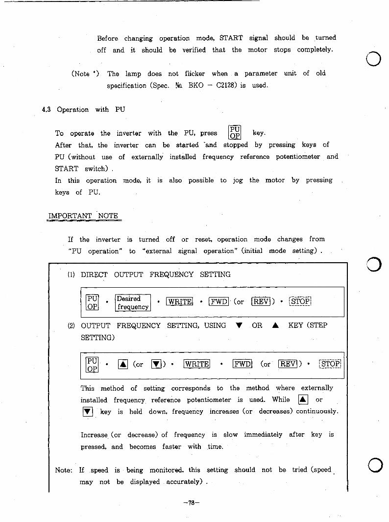
Before changing operation mode, START signal should be ,turned
off and it should be verified that the motor stops completely.
(Note l > The lamp does not flicker when a parameter unit of old
specification (Spec. Na BKO - C2128) is used.
4.3 Operation with PU
PU To operate the inverter with the PU, press op cl
key.
After that, the inverter can be started ‘and stopped by pressing keys of
PU (without use of externally installed frequency reference potentiometer and
START switch) .
In this operation mode, it is also possible to jog the motor by pressing
keys of PU.
IMPORTANT ‘NOTE
If the inverter is turned off or reset, operation mode changes from
“PU operation” to “external signal operation” (initial mode setting) .
(1) DIRECT OUTPUT FREQUENCY SETTING
(2) OUTPUT FREQUENCY SETTING, USING V OR A KEY (STEP
SETTING)
This method of setting corresponds to the method where externally
installed frequency reference potentiometer is used. While q or
q key is held down, frequency increases (or decreases) continuously.
Increase (or decrease) of frequency is slow immediately after key is
pressed, and becomes faster with time.
Note: If speed is being monitored, this setting should not be. tried (speed.
may not be displayed accurately) .
3
0
-78-
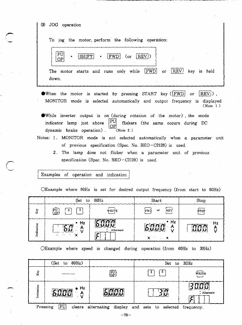
f-
(-
(31 JOG operation
To jog the motor, perform’ the following operation:
PU q l
OP [ml l m (or Ill)
The motor starts and runs only while m] or i-1 key is held
down.
@When the motor is started by pressing START key ((FWDI or [ml > ,
MONITOR mode is selected automatically and output frequency is displayed (Note 1 >
l While inverter output is on (during rotation of the motor) , the mode
indicator lamp just above cl l$ fliekers (the same occurs during DC
dynamic brake operation) . (Note 2 .>
Notes: 1 . MONITOR mode is not selected automatically when a parameter unit
of previous specification (Spec. No. BKO-C2128) is used.
2. The lamp dose not flicker when a parameter unit of previous
specification (Spec. No. BKO-C2128) is used.
Examples of operation and indication
OExample where 60Hz is set for desired output frequency (from start to 60Hz)
Set to 60Hz Start stop
P x g-Jm3
WEE n n
REV pw9 or -, SS
OExample where speed is changed during operation (from 60Hz to 30Hz)
(Set to 60Hz) Set to 30Hz
z cl E W=E
E .s 8 6 2
mj iQfjJ$fl: “A’ fV
Pressing m clears alternating display and sets to selected frequency.
-79-
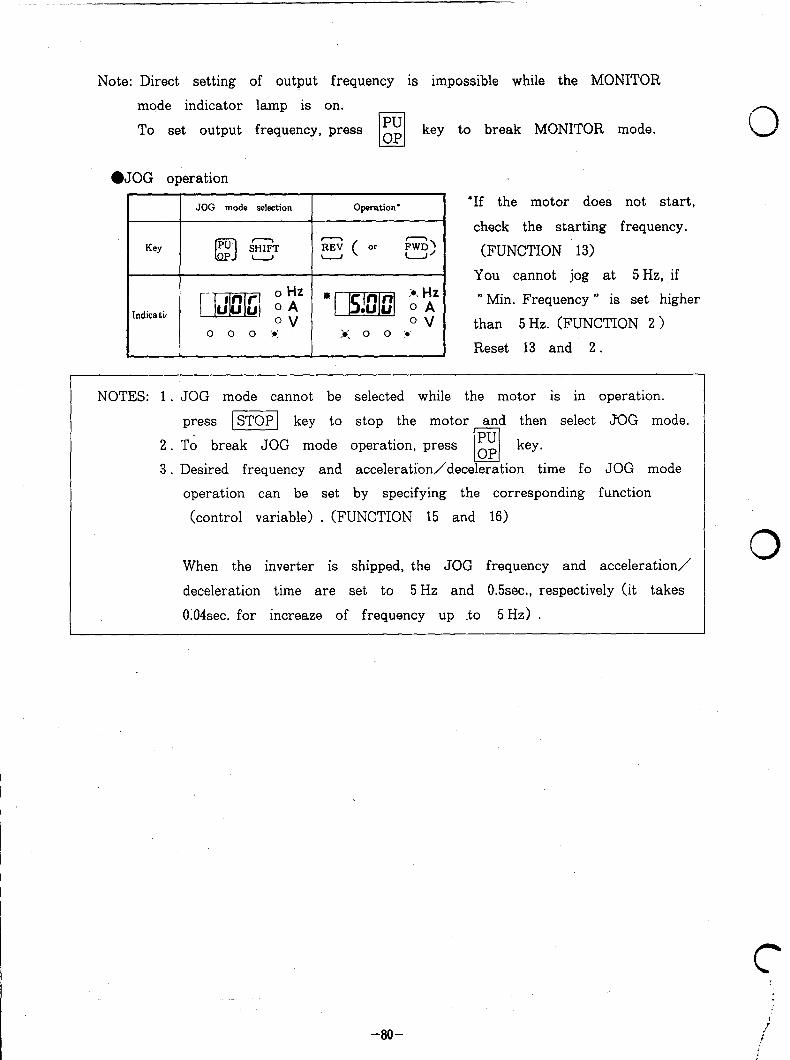
-.-
Note: Direct setting of output frequency is impossible while the MONITOR
mode indicator lamp is on.
To set output frequency, press key to break MONITOR mode.
l JOG operation
Key
JOG mode selection Operation’
hdicatig
0 0 0 b’ ,. 3: 0 0 ..’
*If the motor does not start,
check the starting frequency.
(FUNCTION 13)
You cannot jog at 5 Hz, if
” Min. Frequency ” is set higher
than 5 HZ. (FUNCTION 2 )
Reset 13 and 2 .
NOTES: 1 . JOG mode cannot be selected while the motor is in operation.
press STOP key to stop the motor and then select JOG mode.
2 . To break JOG mode operation, press
3. Desired frequency and acceleration/deceleration time fo JOG mode
operation can be set by specifying the corresponding function
(control variable) . (FUNCTION 15 and 16)
When the inverter is shipped, the JOG frequency and acceleration/
deceleration time are set to 5 Hz and 0.5sec., respectively (it takes
0.04sec. for increaze of frequency up .to 5 Hz) .
0
0
-8O-
c 1 ;
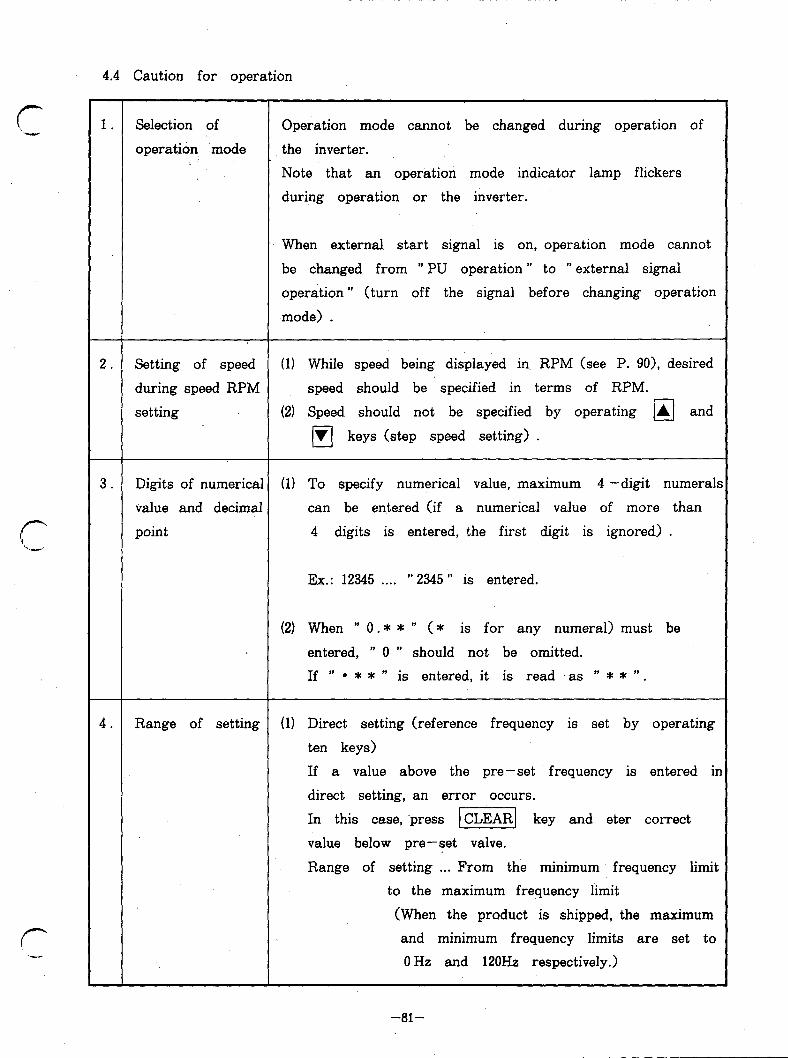
4.4 Caution for operation
r i-,
r
1. Selection of Operation mode cannot be changed during operation of
operation mode the inverter.
Note that an operation mode indicator lamp flickers
during operation or the inverter.
When external start signal is on, operation mode cannot
be changed from ” PU operation ” to ” external signal
operation ” (t urn off the signal before changing operation
mode) .
2. Setting of speed (1) While speed being displayed in. RPM (see P. 901, desired
during speed RPM speed should be specified in terms of RPM.
setting (2) Speed should not be specified by operating A and cl
q V keys (step speed setting) .
3. Digits of numerical (1) To specify numerical value, maximum 4 -digit numerals
value and decimal can be entered (if a numerical value of more than
point 4 digits is entered, the first digit is ignored) .
Ex.: 12345 . . . . ” 2345 ” is entered.
(2) When ” 0. * * ” (* is for any numeral) must be
entered, ” 0 ” should not be omitted.
If ” . * * ” is entered, it is read as ” * * ” .
4. Range of setting (1) Direct setting (reference frequency is set by operating
ten keys)
If a value above the pre-set frequency is entered ir
direct setting, an error occurs.
In this case, ‘press CLEAR key and eter correct 0 value below pre-set valve.
Range of setting . . . From the minimum frequency limit
to the maximum frequency limit
(When the product is shipped, the maximum
and minimum frequency limits are set to
OHz and 120Hz respectively.)
-81-

4. Ex.: If ” 150Hz” is entered, error is displayed as shown
below.
mp=qqQy
This is because the maximum frequency (FUNCTION 1
is already pre-set to 120Hz.
(2) Step setting ( H and/or I‘r( key is pressed to
specify reference frequency)
Reference frequency can be set within the specified
range (from maximum frequency limit to minimum
frequency limit) .
If key is held down while frequency is at the
maximum or minimum limit value, the frequency
remains unchanged.
5. Conditions under (1) ” External signal operation ” mode is selected.
which reference (2) MONITOR mode is selected (step setting is possible
frequency during MONITOR mode) .
(or speed) (3) Reference frequency (speed) is out of the specified
is unacceptable range. (Above or below pre-set max and min
(PU operation frequency. > (FUNCTION . 1 and 2 >
mode)
\ 3
0
0
-82-
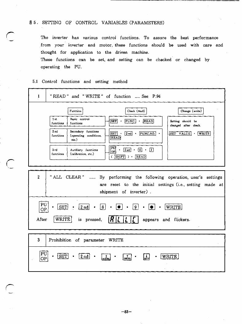
§ 5.
(- hS+V.”
SETTING 0~ CONTROL VARIABLES (PARAMETERS)
The inverter has various control functions. To assure the best performance
from your inverter and motor, these functions should be used with care and
thought for application to the driven machine.
These functions can be set, and setting can be checked or changed by
operating the PU.
Control functions and setting method
1 ” READ ” and ” WRITE ” of function . . . . See P.94
Basic control [ ftztions 1 functions
H~+KEJ.~ 1
Secondary functions (operating conditions,
&C.)
3 rd Auxiliary functions functions (calibration. etc.)
( /ziq ) * piEq
1 Change (write) 1
Setting should be changed after check.
[SET VALUEI l I-1
2 " ALL CLEAR " . . . . . By performing the following operation, user’s settings
are reset to the initial settings (i.e., setting made at
shipment of inverter) .
After pizq is pressed, llTTmKl appears and flickers.
1
I I
I 3l Prohibition of parameter WRITE
-83-
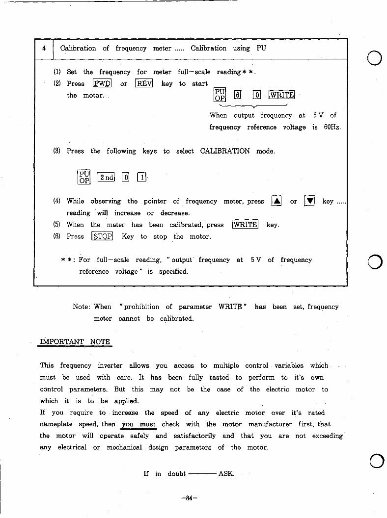
Note: When ” prohibition of parameter WRITE ” has been set, frequency
meter cannot be calibrated.
IMPORTANT NOTE
4 Calibration of frequency meter . . . . . Calibration using PU
(11 Set the frequency for meter full-scale reading* * .
(2) Press m or mj key to start
the motor. 0 g; @ piJ [GEE]
I v When output frequency at 5 V of
frequency reference voltage is 60Hz.
(3) Press the following keys to select CALIBRATION mode.
(41 While observing the pointer of frequency meter, press A or ]rl key . . . .
reading ‘will increase or decrease.
(5) When the meter has been calibrated, ‘press -1 key.
(6) Press m] Key to stop the motor.
* * : For full-scale reading, ” output. frequency at 5 V of frequency
reference voltage ” is specified.
This frequency inverter allows you access to multiple control variables which
must be used with care. It has been fully tasted to perform to it’s own
control parameters. But this may not be the case of the electric motor to
0
0
which it is to be applied.
If you require to increase the speed of any electric motor over it’s rated
nameplate speed, then you must check with the motor manufacturer first, that
the motor will operate safely and satisfactorily and- that you are not exceeding.
any electrical or mechanical design parameters of the motor.
If in doubt 0
ASK.
-a4-
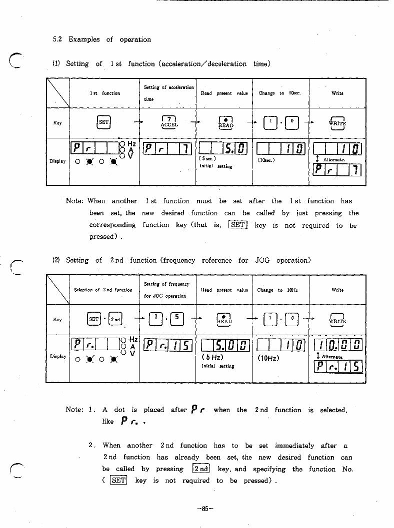
5.2 Examples of operation
(1) Setting of 1 st function (acceleration/deceleration time)
Key 1 m -
Display
Setting of acceleration
Read present value Change to IOsec. Write time
.
Initial setting
Note: When another 1 st function must be set after the 1 st function has
been set, the new desired function can be called by just pressing the
corresponding function key (that is, lsETJ key is not required to be
pressed) .
(2) Setting of 2 nd’ function (frequency reference for JOG operation)
\
KCY
Display
Selection of 2 nd function
@Ia.dj -
Setting of frequency
for JOG operation Read present value Change to 1OHz Write
pjqy-q 1-j [I Irlo.lz_loi (5Hz) (10Hd Initial setting
.
Note: 1 . A dot is placed after p r when the 2 nd function is selected,
like p r. .
2. When another 2 nd function has to be set immediately after a
2 nd function has already been set, the new desired function can
be called by pressing I 2 nd key, and specifying the function No.
( [=I key is not required to be pressed) .
-85-

(3) Setting of 3 rd function (examples of bias and gain settings for frequency
reference voltage signal) .
Selection of 3 rd function
Display
- Bias
0
Note: Do not input frequency
reference signal across terminals
2 and 5.
3
Note: Do not input frequency
reference signal or used 5 V
input signal.
0
-at+
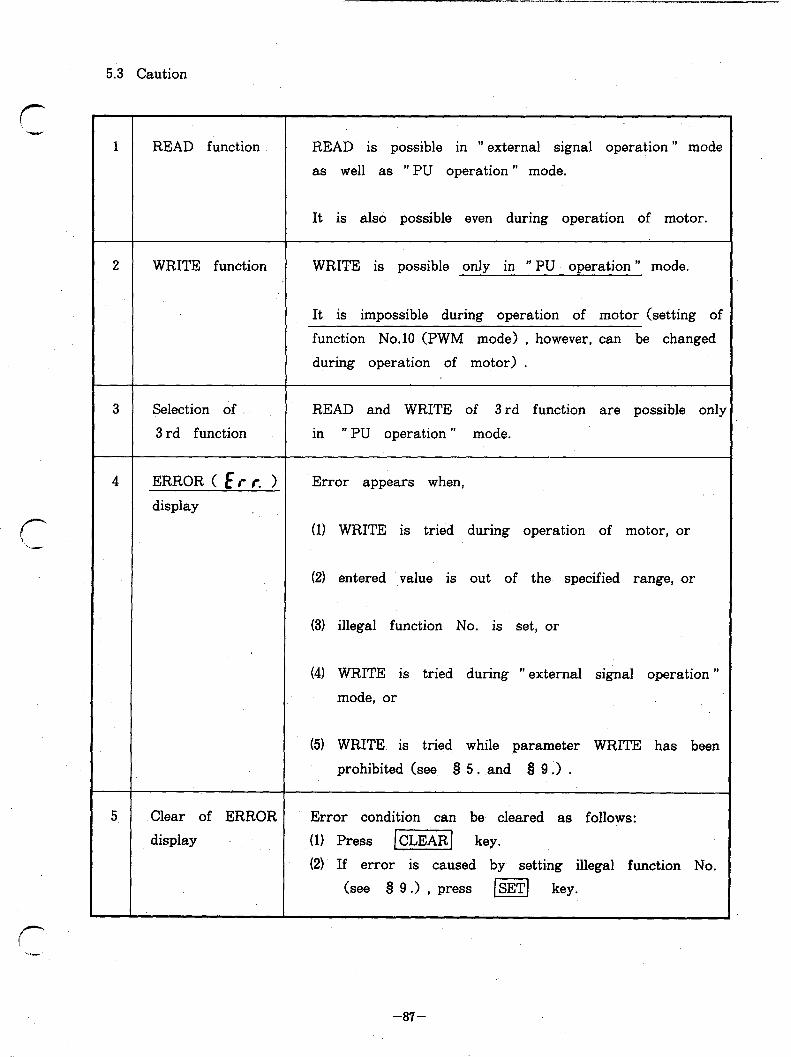
5.3 Caution
1 READ function READ is possible in ” external sign-al operation ” mode
as well as ” PU operation ” mode.
It is also possible even during operation of motor.
2 WRITE function WRITE is possible only in ” PU operation ” mode.
It is impossible during operation of motor (setting of
function No.10 (PWM mode) , however, can be changed
during operation of motor) .
3 Selection of READ and WRITE of 3 rd function are possible only
3 rd function in ” PU operation ” mode.
4 ERROR(Err. > Error appears when,
display
(11 WRITE is tried during operation of motor, or
(21 entered value is out of the specified range, or
(3) illegal function No. is set, or
(41 WRITE is tried during ” external signal operation ”
mode, or
(51 WRITE is tried while parameter WRITE has been
prohibited (see 9 5. and Q 9 :> .
5. Clear of ERROR
display
Error condition can be cleared as follows:
(11 Press [CLEAR] key.
(2) If error is caused by setting illegal function No.
(see 8 9 .> , press m key.
-87-
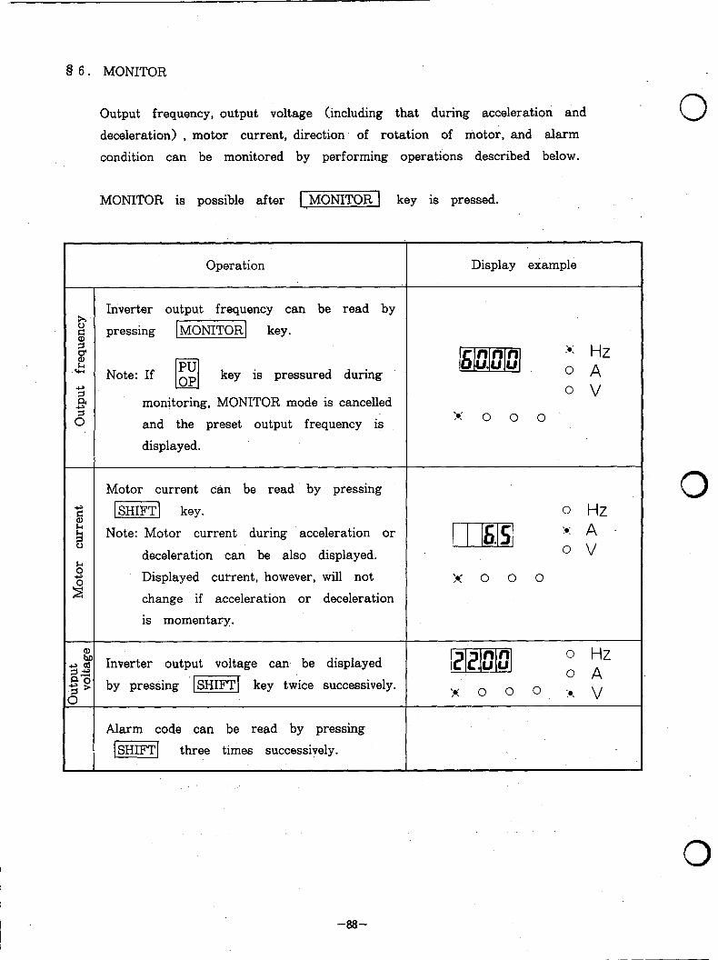
8 6. MONITOR
Output frequency, output voltage (including that during acceleration and
deceleration) , motor current, direction of rotation of motor, and alarm
condition can be monitored by performing operations described below.
MONITOR is possible after -1 key is pressed.
0
Operation Display example
t? Inverter output frequency can be read by
s pressing [MONITORI key. =I. B & Note: If g
a key is pressured during
s 0 v a
3 monitoring, MONITOR mode is cancelled
‘0’ and the preset output frequency is
displayed.
,. 0 0 0
Motor current can be read by pressing
8 -1 key. 0 Hz
2 Note: Motor current during acceleration or
deceleration can be also displayed. . k 5 Displayed current, however, will not . , h 0 0 0 2 change if acceleration or deceleration
is momentary.
; 2 Inverter output voltage can be displayed [Plzlml 0 Hz
$? by pressing 1-l key twice successively.
o *
> , , o o o 9. :a. v
Alarm code can be read by pressing
[i5izFq three times successively.
0
0
-a8-

c
r‘ --,-
Operation Display example
Notes: 1 . The function is capable of storing 0 Hz
a maximum of four alarm codes. lm~ O * Stored alarm codes canbe read 0 v
one after another (see Q 7 for :K o o 0
alarm codes) .
How to read alarm codes (1) For the latest alarm, a dot
is placed by after E (see
r -:-- Dsplay I ;or 1
--‘~~-JGEJ---+piiG] an example shown above) . 3rd ‘2nd 1 st
I latest I alam alana alarm (2) If no alarm has been stored, 1 , alarm ’ -----J the display is as shown
below.
0 When liikiij key is pressed,
s the latest alarm code appears .r( .‘= -2
again.
8
E 0 When IiiGiiiq key is pressed,
A -4 the output frequency at that time
is displayed.
2. Stored alarm codes are held even
after the inverter is turned off.
, ;,..
-89-

Operation Display example
Speed RPM is displayed, instead of inverter) 0 When ” 4 ” is set for number
output frequency, when the following setting of motor poles . . . (In this
has been accomplished. example, inverter output
frequency is assured to be
piq (2 pJ q l ][m\ set at 30Hi previously.)
Number of motor poles is set (within - 0 v
range from 2 poles to 10 poles) .
Speed RPM which corresponds to
inverter output frequency is displayed. l Unit used in display
2 Dis- When speed is monitored in
-3 4
played N= 120X f (Frequency)
P (Number of poles) terms of rpm or m/min,
speed the label which indicates the
2 Note: Displayed speed RPM is in
unit (r-pm or m/min) should
be applied to the monitor proportion to output frequency.
E” display unit over legend ” Hz”
J
a 8 Speed of load (r-pm or m/min) is set c8
- (within range from 11 to 9998) .
.o v
Speed at 60Hz of inverter output frequency
is set.
During ” PU operation ” or ” external
signal operation ” mode, direction of
rotation of the motor can be checked
through the MONITOR indicator lamp.
FORWARD . . . ” Hz ‘I (or ” A ” > lamp lights.
REVERSE . . . “Hz u (or ” A” > lamp flickers.
This lamp flickers when the
motor rotates in reverse
direction.
0
0
0
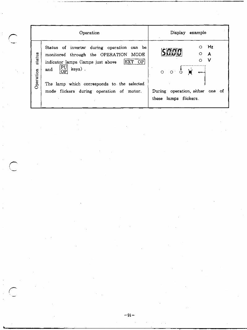
Operation
Status of inverter during operation can be
monitored through the OPERATION MODE
indicator lamps (lamps just above IEXT 0~1
and q g: keys) .
The lamp which corresponds to the selected
mode flickers during operation of motor.
-91-
Display example
During operation, either one of
these lamps flickers.
b 1. I

Q 7. DISPLAY 7.1 Alarm display
If failure occurs during operation of the inverter, an alarm code is displayed.
automatically.
Alarm code Display Code
Description
E 2c : EOC 1 Inverter output current exceeded the overcurrent limit during acceleration.
EcL’z EOCZ Inverter output current exceeded the overcurrent limit during
constant -speed operation.
E333 EOC3 Inverter output current exceeded the overcurrent limit, during
deceleration.
E” UUT EOVT . Braking regenerative power from motor exceeded the regenerative overvoltage limt.
UK? ETHM Electronic thermal relay in the inverter was activated (current
is below 150% of preset current) .
E:fl: ETHT Electronic thermal relay in the inverter was activated (current is over 150% of preset current) .
E: ?f EIPF Instantaneous power failure protective function was activated.
E$: n EFIN Temperature of transistor heatsink exceeded the specified limit.
EbE EBE Brake transistor fault detection.
E nl c ULI EOLT Stall preventive function was activated during constant -speed operation and .stopped the motor.
ff’E EPE Memory in the inverter is corrupted.
E U” tr EUVT Inverter input voltage fell below the specified limit.
E c nr E GF Overcurrent due to earth fault on the inverter output side.
EU”X: EOHT Externally installed thermal relay activated (overheat) .
EU”PT EOPT Built-in optional unit connection failure during operation.
-“rl- -Jo--
0
0
0
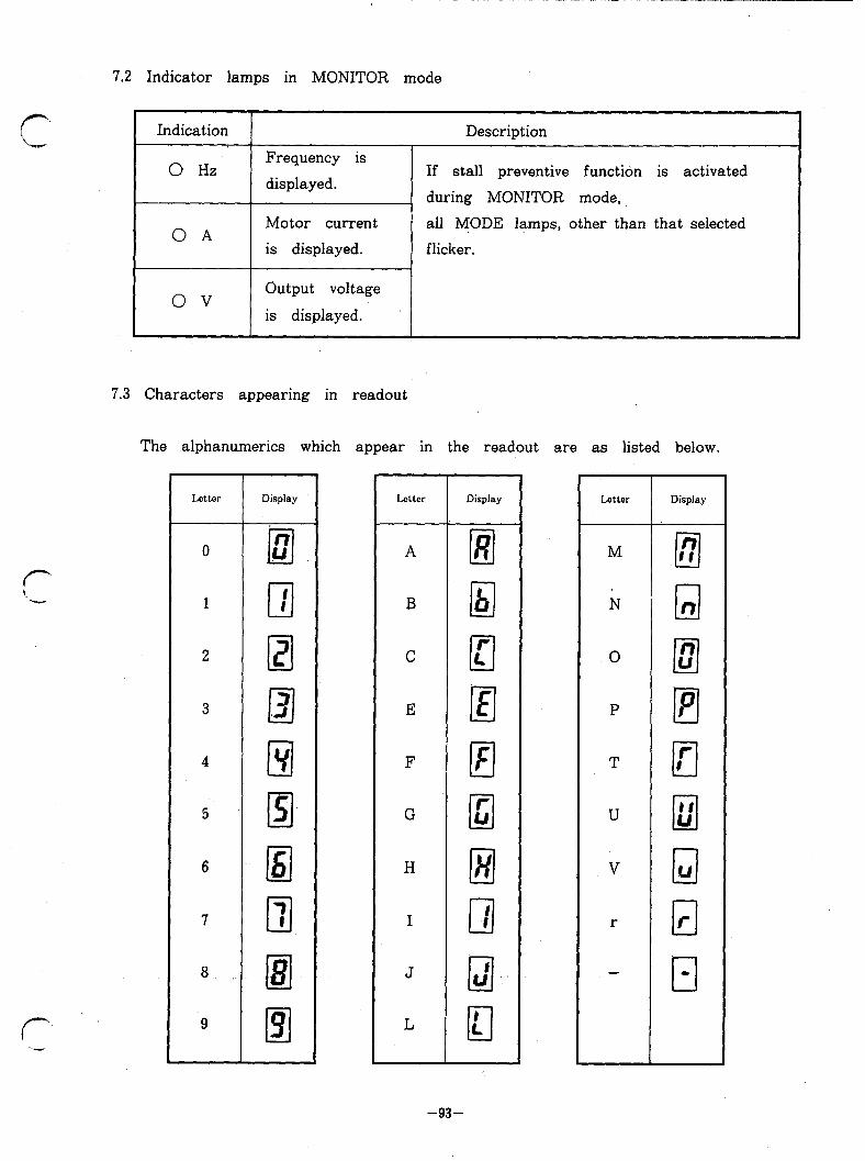
7.2 Indicator lamps in MONITOR mode
Indication
0 Hz Frequency is
displayed.
Description
If stall preventive function is activated
during MONITOR mode,
OA Motor current all MODE lamps, other than that selected
is displayed. flicker.
ov Output voltage
is displayed.
r Y ‘k..-
r
7.3 Characters appearing in readout
The alphanumerics which appear in the readout are as listed below.
Latter Display
0
1
2
3 cl .3 4
5 El
6
7 cl 7
8.
9
Jxttcr
A
B
C
E
F
G
H
I
J
L
Display
El lzl cl c El III cl c
ill u’
cl 1.
-93-
0 cl 2
P El
T cl r I
U II
In U
v Cl w
r cl r

Q 8. LIST OF FUNCTIONS
Function No. Initial (parameter) Function Setting range setting Refer to
0 Torque boost (manual) 0 -30% See P.101 P.101
1 Max. frequency limit 0 -120Hz 120Hz P.98
2 Min. frequency limit 0 -6OHz OHz P.98
3 V/F (base frequency) 50 - 360Hz 50Hz P.102
Fi 4 Multiispeed setting: . ..4 1 st (high speed) 0 -360Hz 608~ P.103 s 5 5 Multi-speed setting: 2 nd (middle speed) 0 -360Hz 30Hz P.103 3 v-4
6 Multi- speed setting: 3 rd (low speed) 0 -360Hz 10Hz P.103
7 Acceleration time 0.1 - 3600sec See P.99 P.99
8 Deceleration time 0.1 - 3600sec See P.99 P.99
9 Electronic thermal relay (overheat) 0 -999.9A See P.99 P.99
10 PWM mode 0 -15 3 P.104
11 DC dynamic brake time 0 -1Osec 0.5sec P.105
12 DC dynamic brake voltage 0 -20% See P.105 P-105
13 Starting frequency 0.5- 10Hz 0.5Hz P.106
‘14 Load pattern selection 0 (constant torque) o 1 (reduced torque) P.102
15 JOG frequency 0 -360Hz 5Hz P.106
f3 16 JOG acceleration/
deceleration time O.l-3600sec 0.5sec P.106 .” s 2 17 deceleration 2 nd acceleration/ time 0.1 - 3600sec 5 set P.100
3 18 High - speed maximum frequency limit
120 - 360Hz 120Hz P-99 hl
19 Base frequency voltage 0 -5oov, 9999 9999 P.102
20 Frequency at 5 V input voltage 1 -360Hz 60Hz P.98
21 Stall prevention level ’ 0 -200% 150% P.107
22 2 nd stall prevention level (current) 0 -200% 150% P.108
23 2 nd stall prevention level (frequency) 0 -360Hz OHz P.108
24 Multi-speed setting: 4 th 0 -360Hz. 9999 9999 P.103
0
0
0
-94-
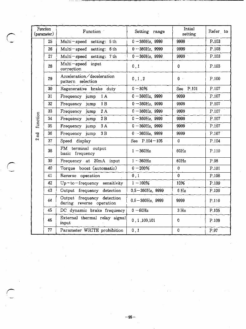
Function (parameter) Function Setting range Intial
setting Refer to
25 Multi-,speed setting: 5 th 0 -360Hz, 9999 9999 P&103
26 Multi-speed setting: 6 th 0 -360Hz, 9999 9999 P.103
27 Multi-speed setting: 7 th 0 -360Hz, 9999 9999 P.103
28 Multi-speed input correction 0,l 0 P.103
29 Acceleration/deceleration pattern selection 0,192 0 P.100
0.5 -360Hz, 9999
46 Exterrkl thermal relay signal o l loo 1ol input tt, 0 P.109
77 Parameter WRITE prohibition 0 1 , 0 P.97
-95-

‘w&ion No. Function Setting range Initial
&m.meter> , setting Refer to
78 Reversing prevention O,l 0 P.97
79 Operation mode selection 0,182 0 P.97
C- 1 Frequency meter calibration 0 -360Hz 60Hz P.111
g c-2 Bias for frequency reference voltage signal
0 -120Hz OHz P.lll
-s j c-3
Gain for frequency reference voltage signal
1 -360Hz 60Hz P.lll
2 c-4 Bias for frequency reference current signal
.O -12OHz OHz P.lll
c- 6 Gain for frequency reference current signal
1 -360Hz* 60Hz P.111
Least setting increments:
Frequency . . . . . . . O.OlHz
Time- . . . . . . . O.lsec.
Current . . . . . . . O.lA
% . ..*... 1%
Voltage . . . . . . . 1v
Note * : When a parameter unit of old specification (Spec. No. BKO-C2128) is
used, the least setting increment of gain for frequency reference current
signal is 1 Hz.
0
0
I 0
-90-

8 9. DETAILS OF EACH FUNCTION
I OPERATION MODE SELECTION, PARAMETER WRITE PROHIBITION ‘AND
REVERSING PREVENTION I
Parameter WRITE prohibition q I-?
WRITE parameter can be prohibited. .
Setting
” 0 ”
. Description
WRITE parameter is possible. (Initial setting)
I 9, 1, 1 I WRITE parameter is impossible. (Note)
Note: Function (parameter) No. 77 and 79 can still be written.
Reversing prevention q q
Reversing of motor operation can be prevented.
Setting Description ’
” 0 ” Motor operation can be reversed. (initial setting)
n ,, 1 Motor operation cannot be reversed. (Note)
Note: Reversing is impossible in ” PU operation ” mode as well as in ” external
signal operation ” mode.
Operation mode selection [91 @l
Operation mode can be fixed to either ” PU operation ” or ” external signal operation ” , or both.
.
Setting ’ Description
” 0 ” Switching between “,PU operation ” and ” external signal
operation ” is possible. (Initial setting)
1, ,t 1 Only ” PU operation ” is possible.
‘99 2 ” Only ” external signal operation ” is possible.
Note: Function (parameter) No. 79 can be changed even in ” external
‘. I
signal operation ” mode.
_ -. . ..- .
-87-

MAXIMUM OUTPUT FREQUENCY SETTING
Frequency with reference voltage signal at 5 V [21 q Frequency with reference current signal at 20mA q •I
Output frequency at DC5 V (or DC lOV> or
20mA of frequency reference signal can be
set. That is, the maximum output frequency
in ” external signal operation ” mode is set.
Acceleration/deceleration time is the time
taken for acceleration or deceleration up O” Fraquemy refersllfe signal 5v (tov) 2OlllA
to the maximum frequency.
Note: The set maximum frequency changes automatically when setting. of ” gain
for frequency reference voltage signal” or ” frequency reference current
signal, gain I’ (see P.36) is changed. Since this function has the priority
level same as that of 3 rd function CC.!- 3 and C- 5 > , priority is given to
the latest set function, when this function is set together with a 3 rd
function.
MAXIMUM/MINIMUM FREQUENCY LIMIT
Maximum frequency limit q Minimum frequency limit [ZJ
Note: When minimum limit frequency is set, 1
it should be higher than the starting g
frequency (see ” Starting frequency d
ency may not be higher than 120Hz.
-----es_-------
,’
- - -
,’ 1 Mu. limit hquency ,’ 1 -setting lnnp
,A--+ ..------A-
Output frequency can be clamped to desired
maximum and/or minimum frequency.
setting ” , P.106) . Maximum limit frequ Frequency reference signd 5V (1OV)
0
0
0
-98-
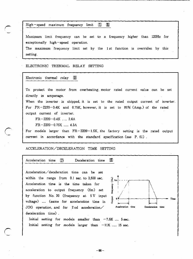
r .-
If- Y
I High -speed maximum frequency limit q q
Maximum limit frequency can be set to a frequency higher than 120Hz for
exceptionally high-speed operation.
The maximum frequency limit set by the 1 st function is overriden by this
setting.
ELECTRONIC THERMAL RELAY SETTING
Electronic thermal relay .191
To protect the motor from overheating, motor rated current value can be set
directly in amperage.
When the inverter is shipped, it is set to the rated output current of inverter.
For FR-Z220-0.4K and 0.75K, however, it is set to 85% (Amp.) of the rated
output current of inverter.
FR-Z220-0.4K . . . . . 2.6A
FR-Z220-0.75K . . . . . 4.3A
For models larger than FR-Z220-1.5K, the factory setting is the rated output
current in accordance with the standard specification (see P. 61) .
ACCELERATION/DECELERATION TIME SETTING
Acceleration time q Deceleration time a
Acceleration/deceleration time can be set
within the range from 0.1 sec. to 3,600 sec.
Acceleration time is the time taken for
acceleration to output frequency (fm> set
by function No. 20 (frequency at 5 V input
voltage) . . . . (same for acceleration time in
JOG operation, and for 2 nd acceleration/
deceleration time) .
Acaderation time Deceleration time
Initial setting for models smaller than -7.5K . . . . 5 sec.
Initial setting for models larger than -1lK . . . . . 15 sec.
-!N-
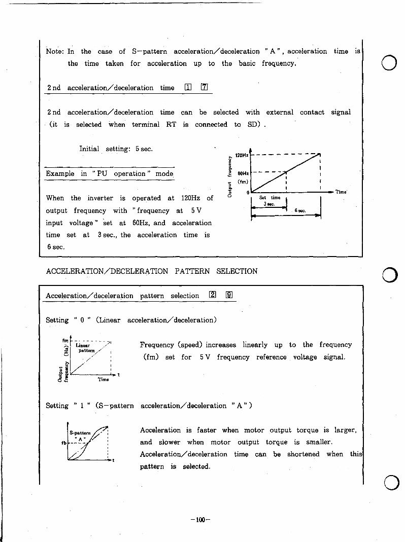
Note: In the case of S-pattern acceleration/deceleration ” A ” , acceleration time is
the time taken for acceleration up to the basic frequency.
2 nd acceleration/deceleration time LI] m
2 nd acceleration/deceleration time can be selected with external contact signal
(it is selected when terminal RT is connected to SD> .
Initial setting: 5 sec.
Example in ” PU operation ” mode
When the inverter is operated at 120Hz of
output frequency with ” frequency at 5 V
input voltage ” set at 60H2, and acceleration
time set at 3 sec., the acceleration time is
6 sec.
~ ,20Hz s t F
- - - - - - - - -
$ )--- I WHZ
/
-- I
I I
m) I I I I 4 5 IlV - Time’
ACCELERATION/DECELERATION PATTERN SELECTION
Acceleration/deceleration pattern selection [z1 q
Setting ” 0 ” (Linear acceleration/deceleration)
Frequency (speed) increases linearly up to the frequency
(fm> set for 5 V frequency reference voltage signal.
t
Setting ” 1 ” (S-pattern acceleration/deceleration ” A ” >
Acceleration is faster when motor output torque is larger,
and slower when motor output torque is smaller.
Acceleration/deceleration time can be shortened when thi t pattern is selected.
-lOO-
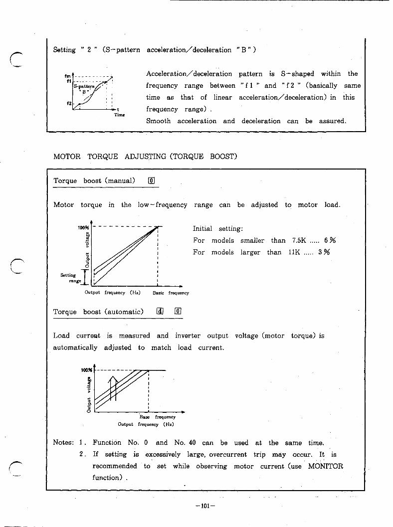
Setting ” 2 ” (S-pattern acceleration/deceleration ” B ” >
Time
Acceleration/deceleration pattern is S-shaped within the
frequency range between ” f 1 ” and ” f 2 ” (basically same
time as that of linear acceleration/deceleration) in this
frequency range) .
Smooth acceleration and deceleration can be assured.
MOTOR TORQUE ADJUSTING (TORQUE BOOST)
Torque boost (manual) q
Motor torque in the low-frequency range can be adjusted to motor load.
,&&- ---- ---- t 2 z I ‘; I P ‘; 0
94. Setting ,
I range ’
Initial setting:
For models smaller
For models larger
than 7.5K . . . . . 6 %
than 11K . . . . . 3 %
Output frequency (Hz) Basic frequency
Torque boost (automatic) Ia lxl
Load current is measured and inverter output voltage (motor torque) is
automatically adjusted to match load current.
‘Base frequency
Output frequency (Hz)
Notes: 1. Function No. 0 and No. 40 can be used at the same time.
2. If setting is excessively large, overcurrent trip may occur. It is
recommended to set while observing motor current (use MObJITOR
function) .
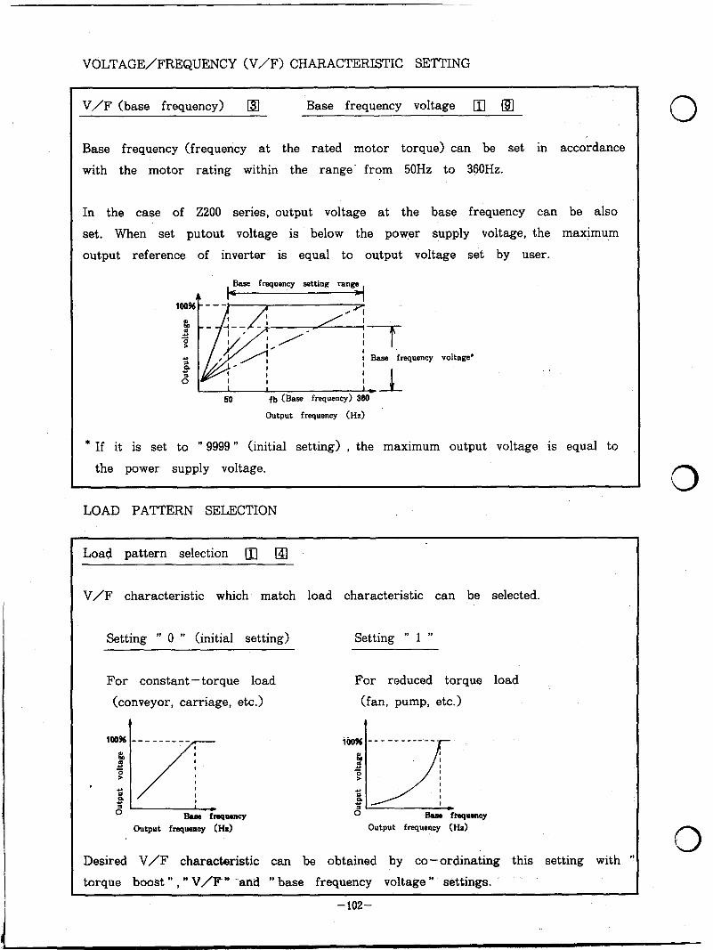
VOLTAGE/FREQUENCY (V/F) CHARACTERISTIC SETTING
V/F (base frequency) @ Base frequency voltage (13 (91
Base frequency (frequency at the rated motor torque) can be set in accordance
with the motor rating within the range’ from 50Hz to 360Hz.
In the case of 2200 series, output voltage at the base frequency can be also
set. When set putout voltage is below the power supply voltage, the maximum
output reference of inverter is equal to output voltage set by user.
Base frequency settine: ran
/- i Base frequency voltage’
I I 1 I I,1
50 fb (Base frequency) 360
Output frequency (Hz)
* If it is set to ” 9999 ” (initial setting) , the maximum output voltage is equal to
the power supply voltage.
LOAD PATTERN SELECTION
Load pattern selection [zl q
V/F characteristic which match load characteristic can be selected.
Setting ” 0 ” (initial setting) Setting ” 1 ”
For constant-torque load
(conveyor, carriage, etc.)
For reduced torque load
(fan, pump, etc.)
lW% --- ------ k!l
’ I/_
B z P 3 I 6 Base fluquency
Output fmquemy 0-h)
Desired V/F characteristic can be obtained by co-ordinating this setting with ”
torque boost ” , ” V/F” -and ” base frequency voltage * settings.
0
0
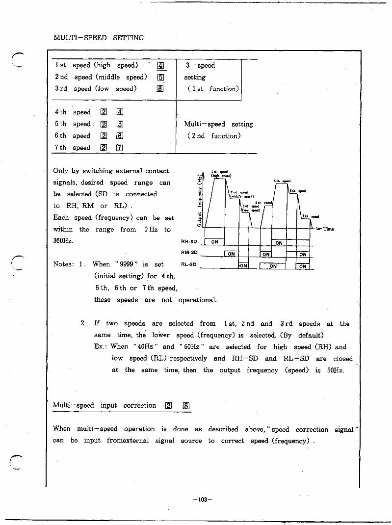
MULTI-SPEED SETTING
1 st speed (high speed) . El 2 nd speed (middle speed) m
3 rd speed (low speed) [61
4 th speed •I &I
5 th speed q q 6 th speed @I 161
7 th speed •I q
3 -speed
setting
( 1 st function)
Multi-speed setting
( 2 nd function)
Only by switching external contact
signals, desired speed range can
be selected (SD is connected
to RH, RM or RL) .
Each speed (frequency) can be set
within the range from OHz to
360Hz.
Notes: 1. When ” 9999 ” is set
Time
(initial setting) for 4 th,
5 th, 6th or 7th speed,
these speeds are not operational.
2. If two speeds are selected from 1 st, 2 nd and 3 rd speeds at the
same time, the lower speed (frequency) is selected. (By default)
Ex.: When ” 40Hz ” and ” 50Hz ” are selected for high speed (RH) and
low speed (RL) respectively and RH- SD and RL -SD are closed
at the same time, then the output frequency (speed) is 50Hz.
Multi-speed input correction @ [IO
When multi-speed operation is done as described above, ” speed correction signal ’
can be input fromexternal signal source to correct speed (frequency) .
-103-
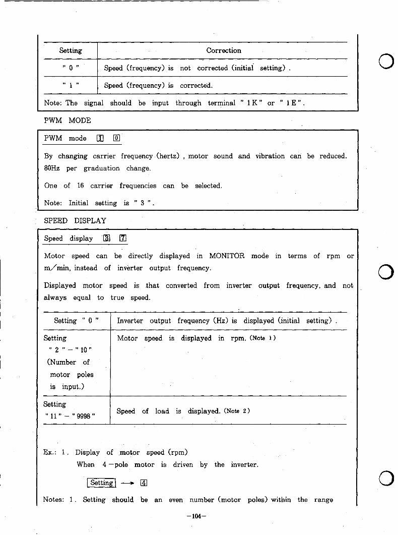
Setting Correction
” 0 ” Speed (frequency) is not corrected (initial setting) .
9. ,, 1 Speed (frequency) is corrected.
Note: The signal should be input through terminal ” 1 K ” or ” 1 E ” .
PWM MODE
PWM mode q q
By changing carrier frequency (hertz) , motor sound and vibration can be reduced.
80Hz per graduation change.
One of 16 carrier frequencies can be selected.
Note: Initial setting is ” 3 ” .
SPEED DISPLAY
Speed display .a 0
Motor speed can be directly displayed in MONITOR mode in terms of rpm or
m/min, instead of inverter output frequency.
Displayed motor speed is that converted from inverter output frequency, and not
always equal to true speed.
Setting ” 0 ” Inverter output frequency (Hz) is displayed (initial setting) .
Setting
” 2 ” - ” 10 ”
(Number of
motor poles
is input.)
Motor speed is displayed ,in rpm. (Note 11
Setting ” 11 ” - ” 9998 ” Speed of load is displayed. (Note 2 >
Ex.: 1 . Display of ,mot.or speed (r-pm)
When 4 -pole motor is driven by the inverter.
Notes: 1 . Setting should be an even number (motor poles) within the range
0
0
-ml-
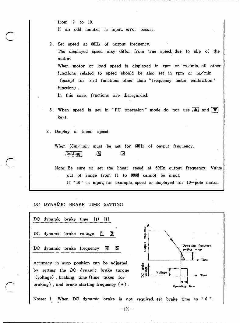
r‘
from 2 to 10.
If an odd number is input, error occurs.
2. Set speed at ‘60Hz of output frequency.
The displayed speed may differ from true speed, due to slip of the
motor.
When motor or load speed is displayed in rpm or m/min, all other
functions related to speed should be also set in rpm or m/min
(except for 3 rd functions, other than ” frequency meter calibration ‘!
function) .
In this case, .fractions are disregarded.
3. When speed is set in ” PU operation ” mode, do not use q and q keys.
2. Display of linear speed
When 55m/min must be set for 60Hz of output frequency,
pziEq El El
Note: Be sure to set the linear speed at 60Hz output frequency. Value
out of range from 11 to 9996 cannot be input.
If ” 10 *’ is input, for example, speed is displayed for lo-pole motor.
DC DYNAMIC BRAKE TIME SETTING
r ‘CM
DC dynamic brake time q ci3
DC dynamic brake voltage 83 [z1
DC dynamic brake frequency q c5)
Accuracy in stop position can be adjusted
by setting the DC dynamic brake torque
(voltage) , braking time (time taken for
braking) , and brake starting frequency ( * ) . Operating time
Notes: 1 . When DC dynamic brake is not required, set brake time to ” 0 “. .-.
-105-
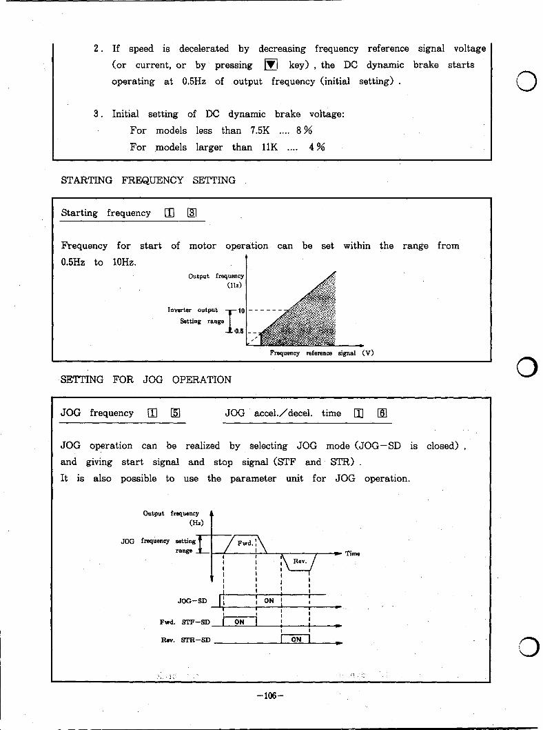
2. If speed is decelerated by decreasing frequency reference signal voltage
(or current, or by pressing m key) , the DC dynamic brake starts
operating at 0.5Hz of output frequency (initial setting) .
3. Initial setting of DC dynamic brake voltage:
For models less than 7.5K . . . . 8 %
For models larger than 11K . . . . 4 %
STARTING FREQUENCY SETTING
Starting frequency [II q
Frequency for start of motor operation can be set within the range from
0.5Hz to 10Hz. output frequency
Inverter output
Setting range
Frequency reference signal (V)
SETTING FOR JOG OPERATION
JOG frequency [II q JOG accel./decel. time q [m
JOG operation can be realized by selecting JOG mode (JOG-SD is closed) ,
and giving start signal and stop signal (STF and STR) .
It is also possible to use the parameter unit for JOG operation.
Output frequency (Hz)
t
Fwd. STF-SD
Rav. =R-SD
0
0
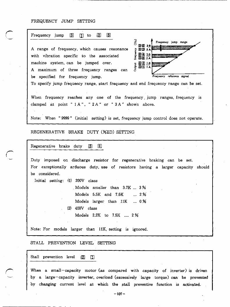
FREQUENCY JUMP SETTING
r .-
f-
Frequency jump q q to •I •I
A range of frequency, which causes resonance $ @lm 3-i
with vibration specific to the associated j @:g,z
machine system, can be jumped over. s rxrtzrrs ,P q ,m 1 A
A maximum of three frequency ranges can 0’
be specified for frequency jump. Frequency reference signal
To specify jump frequency range, start frequency and end frequency range can be set.
When frequency reaches any one of the frequency, jump ranges, frequency is
clamped at point ” 1 A ” , ” 2 A ” or ” 3 A ” shown above.
Note: When ” 9999 ” (initial setting) is set, frequency jump control does not operate.
REGENERATIVE BRAKE DUTY (%ED) SETTING
Regenerative brake duty @J •!
Duty imposed on discharge resistor for regenerative braking can be set.
For exceptionally arduous duty, use of resistors having a larger capacity should
be considered.
Initial setting: (1) ZOOV class
Models smaller than 3.7K . . . 3 %
Models 5.5K and 7.5K . . . 2 %
Models larger than 11K . . . 0 %
(2) 400V class
Models 2.2K to 7.5K . . . . 2 %
Note: For models larger than llK, setting is ignored.
STALL PREVENTION LEVEL SETTING
Stall prevention level [21 q
When a small-capacity motor (as compared with capacity of inverter) is driven
by a large-capacity inverter, overload (excessively large torque) can be prevented
by changing current level at which the stall preventive function is activated.
-107- .

.
Time
Note: Operating current (%> is a ratio of set current to the rated output current
of the inverter.
When setting is zero, the stall preventive functivn is not activated.
2 nd stall prevention level (current) q q
2 nd stall prevention level (frequency) q [51
Stall prevention level can be set in a specific range of currents of frequency.
When level must be below that specified by function No. 21 at frequency lower
than lOHz, 2 nd stall prevention level is set.
REVERSE OPERATION . . . . . using frequency reference signal
Reverse operation @I El Output frequency (Hz)
Direction of rotation of motor can
be reversed only by reversing polarity
of frequency reference signal
(analog signal) . o--f5V For this purpose, auxiliary input
terminals ( 1 K or 1 E) are used. fm terminals 2 and
Rev. v 5 is OV.
Setting Reverse operation
” 0 ” Reverse operation is impossible (operation stops when minus
signal is given) .
., 9. 1 Reverse operation is possible.
When start signal @TF; STR) is not changed and only frequency reference signal
is used toreverse opera&ion, auxiliary input terminals shown above are used.
0
0

r
f-
When other frequency reference voltage signal is applied to terminals 2 and 4 at the same time, the voltage is added to the original reference voltage across
terminals 1 E ( 1 K) and- 5.
EXTERNAL THERMAL RELAY SIGNAL INPUT AND OUTPUT SHUTOFF MODk SELECTION
External thermal relay signal input and output shutoff mode •I q
‘If an externally installed thermal relay is Invertar Thermal relay
activated, the inverter output can be shut off 2200 u and held shut off and the alarm signal can -v ; IM Motor
be. output. w ; JOG/OH
When the external thermal relay is reset s automatically, the inverter does not resume operation automatically.
7
The thermal relay contact signal (normally closed) should be input through terminals JOG/OH-SD. Inverter output can be shut off using terminal MRS, operating mode of which is shown below.
Setting
” 0 ”
II ,t 1
“100”
Function of terminal JOG/OH Function of terminal MRS
JOG mode is selected. Inverter output is shut off when (initial setting) terminals MRS-SD are closed.
External thermal relay is applicable. same as above
JOG mode is selected. Inverter output is shut off when terminals MRS-SD are open.
“101” External thermal relay is applicable. same as above
Note: If ” 1 ” or “ 101” is set while JOG/OH- SD is open, alarm ” OHT ” occurs.
OPEN COLLECTOR OUTPUT ADJUSTMENT AND SELECTION
Up -to-frequency sensitivity @.I q
(Terminal SU> operating
Frequency range within which ” up- to-frequency ” frequency Adjustable range
signal is output can be adjusted within the range B -- from + 1% to +lOO% of operating output frequency. 1 -- _-_
Output frequency detection @ @J ‘; ,P
L!?c
Run Run
8 hme (Terminal FU)
Frequency to be detected can be set within the range from 0 Hz to 360Hz. If output frequency exceeds this point, ” L ” level signal is output from
-109-
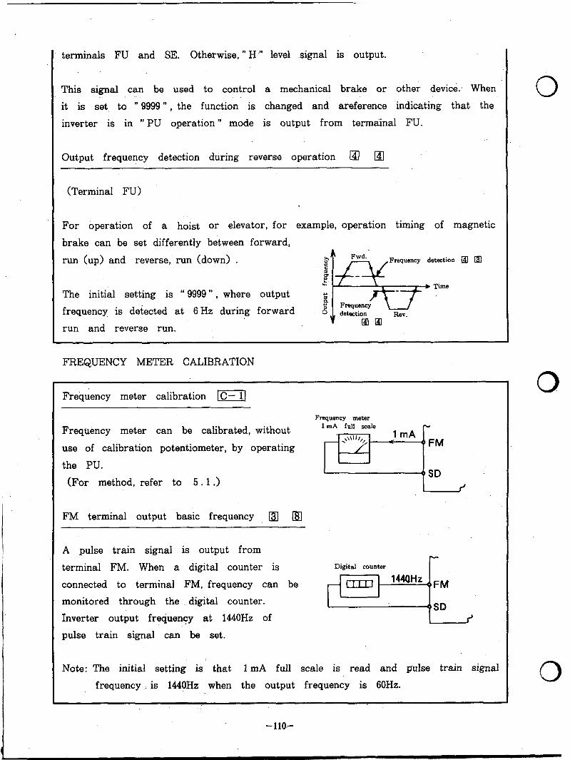
terminals FU and SE. Otherwise, ” H ” level signal is output.
This signal can be used to control a mechanical brake or other device. When
it is set, to ” 9999 ” , the function is changed and areference indicating that the
inverter is in ” PU operation ” mode is output from termainal FU.
Output frequency detection during reverse operation @ •I
(Terminal FU)
For operation of a hoist or elevator, for example, operation timing of magnetic
brake can be set differently between forward,
run (up) and reverse, run (down) . Frequency detection q •0
The initial setting is “ 9999”) where output
frequency is detected at 6 Hz during forward
run and reverse run.
FREQUENCY METER CALIBRATION
Frequency meter calibration m]
Frequency meter
Frequency meter can be calibrated, without
use of calibration potentiometer, by operating
the PU.
(For method, refer to 5.1 .>
FM terminal output basic frequency m q
A pulse train signal is output from
terminal FM. When a digital counter is
connected to terminal FM, frequency can be
monitored through the digital counter.
fnverter output frequency at 1440Hz of
pulse train signal can be set.
I f
Digital counter I-
1 +SD
Note: The initial setting is that 1 mA full scale is read and pulse train signal
frequency ._ is 1440Hz when the output frequency is 60Hz.
. .
- 1 lo-

, * . _ “,“_ . . -_. --__c_I_ _..__ _, . . . . . - -_.-. _._.-.Ic____
r”
f- ‘.*-
OUTPUT FREQUENCY ADJUSTMENT
Bias for frequency reference voltage signal -1
Gain for frequency reference voltage signal I=[
Bias for frequency reference current signal l-4/
Gain for frequency reference current signal I-1
Output frequency ramp for any frequency reference signal as follows
(DC 0 - 5 V, 0 -lOV, 4 -2OmA) can be set.
Output frequency can be set for
frequency reference signal input through
terminals 2 and 5 (or 4 and 5 > .
IGAIN]
T *Gain
1
* When this gain. is specified, value
set for “frequency at 5 V input
voltage ” (function No. 20) or Output frequency can be set for
frequency reference signal input through
terminals 2 and 5 (or 4 and 5 > . ” frequency at 20mA input ” is
When frequency reference signa is 0 V, changed correspondingly.
the signal is judged to be 5 V (or
lOV> , or 2OmA.
-lll-

8 10. PARAMETER UNIT SPECIFICATIONS
Description
Ambient temperature
Operating temperature -10 to +5O”C
Storage temperature -20 to +65”C
Ambient humidity
Less than 90%RH
To be free condensation
Environment
Cooling method
Connection
To be free from oil mist, corrosive gas and dense dust
Self-cooling
Direct installation to FR-Z series inverter, or
connection with special cable
Power supply Fed from FR-Z series inverter
Display 4 -digit 7 -segment LED readout and indicator lamps
Operation 24 keys (protected with polyurethane film> are operated.
Outside dimensions 150mm (high) X 70mm (wide) X l’6mm (deep)
Weight O.lkg
Max. WRITE cycles 100,000 cycles
0
0
0
-112-

8 11 .OUTSIDE DIMENSIONS
l Parameter unit
0 Cable (option>
16
-M3 screw
(Unit: mm>
Inverter side Parameter unit side
Model L cm>
FR-CBLOl 1
FR-CBLOS 3
FR-CBL05 5
-113-