th124e 24806620 12-03-13 - bpt group - bpt group 24806620 12-03-13.pdf · 2 congratulations on the...
TRANSCRIPT

R h
P
24
20
16
1286
22
26
30
323436 24
20
16
1286
23222120191817161514131211109876543210
22
26
30
32343624
20
16
1286
24
20
16
1286
THERMOPROGRAMPROGRAMMABLETHERMOSTAT
TH124
INSTRUCTIONS FOR USETH124E 24806620 12-03-13
TH124E 24806620 12-03-13.qxd 13-03-2013 11:34 Pagina 1

2
Congratulations on the purchase of this TH124thermostat.For best performance and to enable the best useof this programmable thermostat’s characteristicsand functions please read this manual carefully andkeep it available for future reference.
WARNINGS FOR THE INSTALLER
• Read the warnings contained herein with care asthey furnish important instructions regarding safeuse, installation and maintenance.• After removing the packaging check the condi-tion of the unit.• The system must be installed in compliance withcurrent safety standards.• The manufacturer declines all liability for anydamage as a result of improper, incorrect or unrea-sonable use.• Should the unit be in need of repair contact onlya technical support centre authorised by the man-ufacturer.• Failure to comply with the above instructionsmay compromise the unit’s safety.
TH124E 24806620 12-03-13.qxd 13-03-2013 11:34 Pagina 2

3
THERMOPROGRAMTH124The TH124 THERMOPROGRAM programmablethermostat has been designed to guarantee idealtemperature conditions at all times during the day.Installation takes only minutes. The thermostat canbe connected to the heating/cooling installationsimply by means of two wires.Three alkaline LR6 1.5 V penlight AAA batteries areused to power THERMOPROGRAM for over ayear.It can be programmed easily using the sliders; thelarge display shows the time and ambient temper-ature together with all programmed data.The thermal differential is adjustable from 0.1 °C to0.9°C
The THERMOPROGRAM can control both heat-ing and air-conditioning systems, and can beinstalled as a replacement for a previous on/offprogrammable thermostat.
TH124E 24806620 12-03-13.qxd 13-03-2013 11:34 Pagina 3
4
R h
P
24
20
16
1286
22
26
30
323436 24
20
16
1286
23222120191817161514131211109876543210
22
26
30
32343624
20
16
1286
6 7 8 18 19 20 21
22
11
23
12
4 9 14 1615 17
24
20
16
1286
13
3
5
12
Fig. 1
10
TH124E 24806620 12-03-13.qxd 13-03-2013 11:34 Pagina 4

5
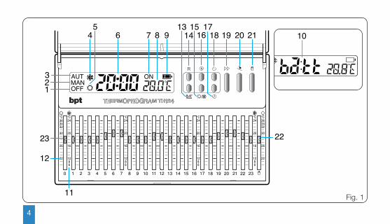
SYMBOLS (fig. 1)
1 OFF System bypass symbol.
2 MAN MANUAL operating mode symbol.
3 AUT AUTOMATIC operating mode symbol.
4 Heating mode symbol.
5 Cooling mode symbol.
6 Digital clock.
7 ON System operational symbol.
8 Digital thermometer.
9 Battery charge status.
10 When this warning appears, it meansthat the batteries are exhausted .
11 6÷24°C Heating programme temperaturerange ( ).
12 20÷36°C Cooling programme temperaturerange ( ).
CONTROLS (fig. 1)
13 Display ProgrammedTemperature/Thermal Differentialbutton.
14 R Reset button
15 Cooling ( ) or heating programmeselect button ( ).
16 View accumulated system operat-ing hours button.
17 Clock set button.
P
h
TH124E 24806620 12-03-13.qxd 13-03-2013 11:34 Pagina 5

18 System bypass or operating hourscounter rest button.
19 Advance button.
20 HOLIDAY PROGRAMME activationbutton.
21 MANUAL or AUTOMATIC operatingmode select button.
22 MANUAL mode temperatureadjustment slider.
6
23 Sliders for setting the hourly tem-perature in AUTOMATIC mode.The slider colour indicates the sys-tem’s operating periods (excludingthe municipalities belonging to zoneF) in accordance with the D.P.R. n.412.Red=comfort Blue=economy
0÷23
TH124E 24806620 12-03-13.qxd 13-03-2013 11:34 Pagina 6

7
CONTENTS
Chapter Page
1 - Position 8
2 - Installation 8
3 - Power supply 12
4 - Thermal differential 14
5 - Setting the clock 16
6 - Heating or cooling programme 17
7 - Automatic operation 17
8 - Manual operation 18
9 - Holiday programme 19
10 - Accumulated system operating time 22
11 - Displaying the programmed temperatures 22
12 - System bypass 23
13 - Temporary system bypass 24
14 - Battery replacement 26
15 - Thermostat fault condition 30
16 - Technical characteristics 30
TH124E 24806620 12-03-13.qxd 13-03-2013 11:34 Pagina 7
8
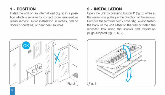
1 - POSITIONInstall the unit on an internal wall (fig. 2) in a posi-tion which is suitable for correct room temperaturemeasurement. Avoid installation in niches, behinddoors or curtains, or near heat sources
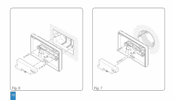
2 - INSTALLATIONOpen the unit by pressing button P (fig. 3) while atthe same time pulling in the direction of the arrows.Remove the terminal block cover (fig. 4) and fastenthe back of the unit either to the wall or within therecessed box using the screws and expansionplugs supplied (fig. 5, 6, 7).
P
Fig. 3
OK
Fig. 2
TH124E 24806620 12-03-13.qxd 13-03-2013 11:34 Pagina 8

9
Fig. 4 Fig. 5
TH124E 24806620 12-03-13.qxd 13-03-2013 11:34 Pagina 9
10
Fig. 6 Fig. 7
TH124E 24806620 12-03-13.qxd 13-03-2013 11:34 Pagina 10
11
NC C NA
L N
U1
Fig. 8
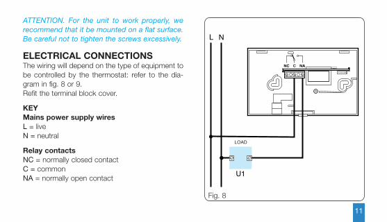
ATTENTION. For the unit to work properly, werecommend that it be mounted on a flat surface.Be careful not to tighten the screws excessively.
ELECTRICAL CONNECTIONSThe wiring will depend on the type of equipment tobe controlled by the thermostat: refer to the dia-gram in fig. 8 or 9. Refit the terminal block cover.
KEYMains power supply wiresL = liveN = neutral
Relay contactsNC = normally closed contactC = commonNA = normally open contact
LOAD
TH124E 24806620 12-03-13.qxd 13-03-2013 11:34 Pagina 11

12
NC C NA
L N
U2
M
Fig. 9
LoadsU1 = boiler, circulation pump, solenoid valve, etc.U2 = motorised valve
3 - POWER SUPPLYInsert three new alkaline LR6 penlight AAA 1.5Vbatteries of the same type. Make sure the polesface the way that is shown on the bottom of thehousing (fig. 10).ATTENTION. Inserting the batteries the wrongway round could damage the unit.If the indications on the display do not appearwithin 30 seconds, press the reset button R.Close the unit making sure that the hooks areinserted into the slots (fig. 11).Once the batteries have been inserted the displaycomes on featuring the indications illustrated in fig.12 The unit is now set to operate in automatic AUTheating mode .
LOADCLOSE
OPEN
TH124E 24806620 12-03-13.qxd 13-03-2013 11:34 Pagina 12

13
Fig. 10 Fig. 11
TH124E 24806620 12-03-13.qxd 13-03-2013 11:34 Pagina 13
14
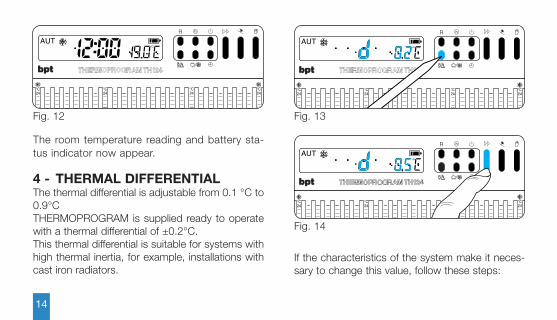
If the characteristics of the system make it neces-sary to change this value, follow these steps:
Fig. 14
The room temperature reading and battery sta-tus indicator now appear.
4 - THERMAL DIFFERENTIALThe thermal differential is adjustable from 0.1 °C to0.9°CTHERMOPROGRAM is supplied ready to operatewith a thermal differential of ±0.2°C. This thermal differential is suitable for systems withhigh thermal inertia, for example, installations withcast iron radiators.
Fig. 13
R h
P
°C24
20
°C24
20
°C24
20
°C24
20
h
P
°C24
°C24
°C24
°C24
R
Fig. 12
R h
P
°C24
20
°C24
20
°C24
20
°C24
20
TH124E 24806620 12-03-13.qxd 13-03-2013 11:34 Pagina 14
15
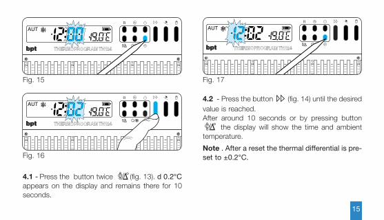
4.1 - Press the button twice (fig. 13). d 0.2°Cappears on the display and remains there for 10seconds.
P
Fig. 15
Fig. 16
h
P
°C24
°C24
°C24
°C24
R
h
P
°C24
20
°C24
20
°C24
20
°C24
20
R
Fig. 17
h
P
°C24
20
°C24
20
°C24
20
°C24
20
R
4.2 - Press the button (fig. 14) until the desiredvalue is reached.After around 10 seconds or by pressing button
the display will show the time and ambienttemperature.
Note . After a reset the thermal differential is pre-set to ±0.2°C.
P
TH124E 24806620 12-03-13.qxd 13-03-2013 11:34 Pagina 15
16
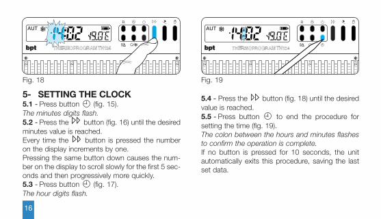
5.4 - Press the button (fig. 18) until the desiredvalue is reached.5.5 - Press button to end the procedure forsetting the time (fig. 19).The colon between the hours and minutes flashesto confirm the operation is complete.If no button is pressed for 10 seconds, the unitautomatically exits this procedure, saving the lastset data.
5- SETTING THE CLOCK5.1 - Press button (fig. 15).The minutes digits flash.5.2 - Press the button (fig. 16) until the desiredminutes value is reached.Every time the button is pressed the numberon the display increments by one. Pressing the same button down causes the num-ber on the display to scroll slowly for the first 5 sec-onds and then progressively more quickly.5.3 - Press button (fig. 17).The hour digits flash.
Fig. 18
h
P
°C24
20
°C24
20
°C24
20
°C24
20
R
Fig. 19
h
P
°C24
20
°C24
20
°C24
20
°C24
20
R
TH124E 24806620 12-03-13.qxd 13-03-2013 11:34 Pagina 16
17
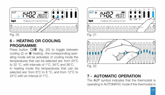
6 - HEATING OR COOLING PROGRAMMEPress button (fig. 20) to toggle betweencooling or heating , the corresponding oper-ating mode will be activated. In cooling mode thetemperatures that can be selected are: from 20°Cto 32 °C, with intervals of 1°C, 34°C and 36°C. In heating mode the temperatures that can beselected are: from 6°C to 8 °C, and from 12°C to24°C with an interval of 1°C.
Fig. 20
h
P
°C24
20
°C24
20
°C24
20
°C24
20
R
Fig. 21
h
P
°C24
20
°C24
20
°C24
20
°C24
20
R
Fig. 22
°C24
20
16
1286
°C24
20
16
1286
23222120191817161514131211109876543210
°C24
20
16
1286
°C24
20
16
1286
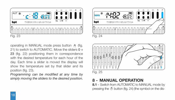
7 - AUTOMATIC OPERATIONThe AUT symbol indicates that the thermostat isoperating in AUTOMATIC mode If the thermostat is
TH124E 24806620 12-03-13.qxd 13-03-2013 11:34 Pagina 17
18
8 - MANUAL OPERATION8.1 - Switch from AUTOMATIC to MANUAL mode bypressing the button (fig. 24) (the symbol on the dis-
operating in MANUAL mode press button (fig.21) to switch to AUTOMATIC. Move the sliders 0 ÷23 (fig. 22) positioning them in correspondencewith the desired temperature for each hour of theday. Each time a slider is moved the display willshow the temperature set by that slider and itsposition (fig. 23).Programming can be modified at any time bysimply moving the sliders to the desired position.
Fig. 23
h
P
°C24
°C24
°C24
°C24
R
Fig. 24
h
P
°C24
20
°C24
20
°C24
20
°C24
20
R
Fig. 25
°C24
20
16
1286
232221201918171615141312111098765432
22
26
30
323436°C°C
24
20
16
1286
°C24
20
16
1286
TH124E 24806620 12-03-13.qxd 13-03-2013 11:34 Pagina 18
19
Fig. 26
h
P
°C24
20
°C24
20
°C24
20
°C24
20
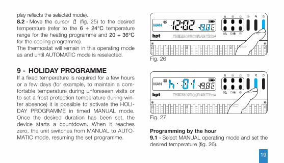
Rplay reflects the selected mode).8.2 - Move the cursor (fig. 25) to the desiredtemperature (refer to the 6 ÷ 24°C temperaturerange for the heating programme and 20 ÷ 36°Cfor the cooling programme).The thermostat will remain in this operating modeas and until AUTOMATIC mode is reselected.
9 - HOLIDAY PROGRAMMEIf a fixed temperature is required for a few hoursor a few days (for example, to maintain a com-fortable temperature during unforeseen visits orto set a frost protection temperature during win-ter absence) it is possible to activate the HOLI-DAY PROGRAMME in timed MANUAL mode.Once the desired duration has been set, thedevice starts a countdown. When it reacheszero, the unit switches from MANUAL to AUTO-MATIC mode, resuming the set programme.
Programming by the hour9.1 - Select MANUAL operating mode and set thedesired temperature (fig. 26).
Fig. 27
h
P
°C24
°C24
°C24
°C24
R
TH124E 24806620 12-03-13.qxd 13-03-2013 11:34 Pagina 19

20
9.2 - Press button (fig. 27).In place of the current time h01 will appear.9.3 - Press button (fig. 28) until the desired num-ber of hours is reached from 1 to 99.The hours count includes those when program-ming is performed. The remaining part of the hourwhen the operation is performed is thereforecounted as one hour.Note. To return to AUTOMATIC operating modebefore the programmed period expires press the
button (fig. 29).
Programming by the day9.4 - Select MANUAL operating mode and set thedesired temperature (fig. 30).
Fig. 28
h
P
°C24
20
°C24
20
°C24
20
°C24
20
R
Fig. 29
h
P
°C24
20
°C24
20
°C24
20
°C24
20
R
Fig. 30
h
P
°C24
20
°C24
20
°C24
20
°C24
20
R
TH124E 24806620 12-03-13.qxd 13-03-2013 11:34 Pagina 20

21
Fig. 31
h
P
°C24
°C24
°C24
°C24
R
Fig. 32
h
P
°C24
°C24
°C24
°C24
R
9.5 - Press the button twice (fig. 31).In place of the current time d01 will appear.
Fig. 33
h
P
°C24
20
°C24
20
°C24
20
°C24
20
R
9.6 - Press button (fig. 32) until the desirednumber of hours is reached from 1 to 99. The days count includes those when programmingis performed. The remaining part of the day whenthe operation is performed is therefore counted asone day.Note. To return to AUTOMATIC operating modebefore the programmed period expires press the
button (fig. 33).
TH124E 24806620 12-03-13.qxd 13-03-2013 11:34 Pagina 21

22
10 - ACCUMULATED SYSTEMOPERATING TIMETHERMOPROGRAM features an hour-counter (upto 9,999), which records the system’s overall num-ber of operating hours for each temperature level.10.1 - Press button (fig. 34).For 5 seconds the display will reveal the number ofaccumulated operating hours of operation of thesystem that is connected to THERMOPROGRAM.To reset the counter press buttons and oneafter the other (within 5s) (fig. 34 and fig. 35). Afterthe reset the counter will automatically restart.
h
h
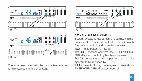
11 - DISPLAYING THE PROGRAMMED TEMPERATURES11.1 - Press button (fig. 36).For 5 seconds the display will reveal the set tem-perature associated with the indicated hour. For example is the clock displays 11.45 and theslider associated with that hour (C11) is positionedat 20°C, the display will reveal C11 20°C.11.2 - Press button (fig. 37) to display the tem-peratures associated with the other sliders.
P
Fig. 34
h
P
°C24
20
°C24
20
°C24
20
°C24
20
R
Fig. 35
h
P
°C24
20
°C24
20
°C24
20
°C24
20
R
TH124E 24806620 12-03-13.qxd 13-03-2013 11:34 Pagina 22
23
Fig. 36
h
P
°C24
20
°C24
20
°C24
20
°C24
20
R
Fig. 37
h
P
°C24
°C24
°C24
°C24
R
The slider associated with the manual temperatureis indicated by the reference C25.
Fig. 38
h
P
°C24
20
°C24
20
°C24
20
°C24
20
R
12 - SYSTEM BYPASSSystem bypass is useful during cleaning, mainte-nance work, or when absent, etc. The unit simplyfunctions as a clock and room thermometer12.1 - Press button (fig. 38).The OFF symbol confirms that THERMOPRO-GRAM system control by has been bypassed.For 5 seconds the room temperature reading dis-appears to be replaced by . 12.2 -Press button once again to re-establishTHERMOPROGRAM system control.
TH124E 24806620 12-03-13.qxd 13-03-2013 11:34 Pagina 23
24
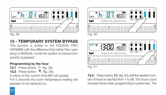
13 - TEMPORARY SYSTEM BYPASSThis function is similar to the HOLIDAY PRO-GRAMME with the difference that rather than oper-ating in MANUAL mode the system is instead tem-porarily bypassed.
Programming by the hour13.1 - Press button (fig. 38).13.2 - Press button (fig. 39).In place of the current time h01 will appear.For 5 seconds the room temperature reading dis-appears to be replaced by .
13.3 - Press button (fig. 40) until the desired num-ber of hours is reached from 1 to 99. The hours countincludes those when programming is performed. The
Fig. 39
h
P
°C24
°C24
°C24
°C24
R
Fig. 40
h
P
°C24
20
°C24
20
°C24
20
°C24
20
R
Fig. 41
h
P
°C24
20
°C24
20
°C24
20
°C24
20
R
TH124E 24806620 12-03-13.qxd 13-03-2013 11:34 Pagina 24
25
Fig. 42
h
P
°C24
20
°C24
20
°C24
20
°C24
20
R
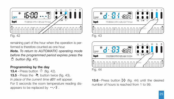
remaining part of the hour when the operation is per-formed is therefore counted as one hour.Note. To return to AUTOMATIC operating modebefore the programmed period expires press the
button (fig. 41).
Programming by the day13.4 - Press button (fig. 42).13.5 - Press the button twice (fig. 43).In place of the current time d01 will appear.For 5 seconds the room temperature reading dis-appears to be replaced by .
Fig. 43
h
P
°C24
°C24
°C24
°C24
R
13.6 - Press button (fig. 44) until the desirednumber of hours is reached from 1 to 99.
Fig. 44
h
P
°C24
°C24
°C24
°C24
R
TH124E 24806620 12-03-13.qxd 13-03-2013 11:34 Pagina 25
26
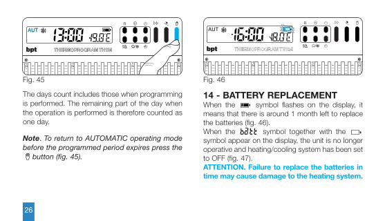
The days count includes those when programmingis performed. The remaining part of the day whenthe operation is performed is therefore counted asone day.
Note. To return to AUTOMATIC operating modebefore the programmed period expires press the
button (fig. 45).
14 - BATTERY REPLACEMENTWhen the symbol flashes on the display, itmeans that there is around 1 month left to replacethe batteries (fig. 46). When the symbol together with the symbol appear on the display, the unit is no longeroperative and heating/cooling system has been setto OFF (fig. 47). ATTENTION. Failure to replace the batteries intime may cause damage to the heating system.
Fig. 45
h
P
°C24
°C24
°C24
°C24
R
Fig. 46
h
P
°C24
°C24
°C24
°C24
R
TH124E 24806620 12-03-13.qxd 13-03-2013 11:34 Pagina 26
27
Fig. 47
h
P
°C24
20
°C24
20
°C24
20
°C24
20
R
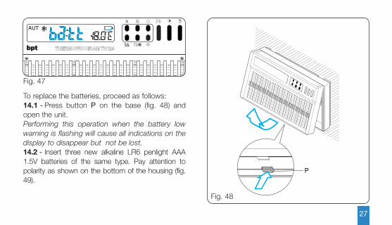
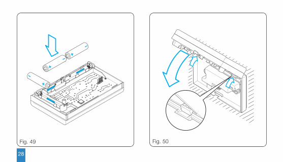
To replace the batteries, proceed as follows:14.1 - Press button P on the base (fig. 48) andopen the unit.Performing this operation when the battery lowwarning is flashing will cause all indications on thedisplay to disappear but not be lost.14.2 - Insert three new alkaline LR6 penlight AAA1.5V batteries of the same type. Pay attention topolarity as shown on the bottom of the housing (fig.49).
P
Fig. 48
TH124E 24806620 12-03-13.qxd 13-03-2013 11:34 Pagina 27
28
Fig. 49 Fig. 50
TH124E 24806620 12-03-13.qxd 13-03-2013 11:34 Pagina 28

29
If the indications on the display do not appearwithin 30 seconds, press the reset button R.Warning! Inserting the batteries the wrongway round could damage the unit.There will be approximately 2 minutes avail-able for replacing the batteries. If the batteries are not replaced with theavailable period or if the reset button R ispressed all settings will be lost. To restart the unit, proceed as described inchapter 4. Close the unit. Make sure that the hooks havebeen inserted in their proper places (fig. 50). Aftera few seconds the information on the display willreappear.
h
P
°C24
20
16
1286
22
26
30
323436°C °C
24
20
16
1286
23222120191817161514131211109876543210
22
26
30
323436°C°C
24
20
16
1286
°C24
20
16
1286
R
Fig. 51
TH124E 24806620 12-03-13.qxd 13-03-2013 11:34 Pagina 29

• Autonomy: over 1 year.• Battery low warning.• Time available for battery replacement: approxi-
mately 2 minutes.• Relay: max. voltage 250 V, max. current 5A with
resistive load (2A with inductive load).Type of action: 1B-U.
• Range of adjustment: from 6°C to 24 °C• Range of adjustment: from 20°C to 36 °C• Three operating modes: MANUAL, AUTOMAT-
IC, SYSTEM BYPASS• Selectable programmes HEATING, COOLING• Accumulated system operating hours counter
(from 1 to 9.999).• Manual mode timer or system bypass in hours or
days up to a maximum of 99.• Room temperature measuring interval: 15s.• Thermal differential: adjustable from 0.1 °C to
0.9°C• Reading resolution: 0,1°C.
30
15 - THERMOSTAT FAULT CONDITIONIn the event of an error condition press button R toreset the thermostat.This operation will cause the loss of all savedsettings. They can be restored following theprocedure described in chapter 4 onwards.The appearance on the display of error messagesfrom E00÷E23 or E25 (manual slider error), indi-cate that the slider associated with that hour posi-tion is not correctly positioned. To remedy this con-dition simply mode the slider until the error mes-sage clears (fig. 51).
16 - TECHNICAL CHARACTERISTICSUnit for domestic use.• Independently installed electronic device.• LCD display.• Power supply: 3 alkaline LR6 penlight AAA 1.5V
batteries.
TH124E 24806620 12-03-13.qxd 13-03-2013 11:34 Pagina 30

DISPOSAL
Do not litter the environment with packaging mate-rial: make sure it is disposed of according to theregulations in force in the country where the prod-uct is to be used.When the equipment reaches the end of its lifecycle, avoid discarding it within the environment.The equipment must be disposed of in compliancewith current regulations, recycling its componentparts wherever possible.Components that qualify as recyclable waste fea-ture the relevant symbol and material acronym.
31
• Displayed reading range: from 0°C to +40°C• Precision: ≤ ±0,3°C.• Class A software.• Degree of pollution: 2.• Impulse voltage: 4 kV.• Maximum control unit temperature: 40 °C.• Operating temperature: from 0°C to +40°C.• Protection rating: IP30.• Dimensions: 132 x 82 x 33.5mm.
TH124E 24806620 12-03-13.qxd 13-03-2013 11:34 Pagina 31

BPT S.p.A. a Socio UnicoVia Cornia, 133079 Sesto al [email protected]
TH124E 24806620 12-03-13.qxd 13-03-2013 11:34 Pagina 32