tf/td/tv series single, dual, and variable displacement …saihyd.com/pdf/t.pdf · 3 130766.9 t...
TRANSCRIPT

TF/TD/TV Series
Single, Dual, and Variable Displacement
Motors

1
www.saispa.com 130766.9
T SERIES TECHNICAL CATALOGUE CATALOGO TECNICO SERIE T
TF1.5
240 340 400
Equivalent displacement ⁽¹⁾ [cc/rev]
241 341 405
Cilindrata equivalente ⁽¹⁾ Bore
[mm]
37 44 48
Alesaggio Stroke
[mm]
32
Corsa Specific torque
[Nm/bar]
3,82 5,43 6,45
Coppia specifica Continuous pressure
[bar]
350
Pressione in continuo Peak pressure ⁽³⁾
[bar]
450 450
Pressione di picco ⁽³⁾ Peak power ⁽⁴⁾
[kW]
110
Potenza di picco ⁽⁴⁾ Continuous speed
[rpm]
700 700 650
Velocità in continuo Maximum speed
[rpm]
900 900 800
Velocità massima Approximative weight
[kg] 51 unit Motor oil capacity
[l] 0,8 Peso approssimativo unità Capacità olio motore
Maximum casing pressure [bar]
5 continuous
Admissible temperatures [°C]
-20 minimum
continuo minimo
Pressione massima in carcassa 15 peak
Temperature ammissibili +80 maximum
picco massimo
Override change displacement pilot pressure range
[bar] 15 ÷ 40
Override change displ. pilot oil capacity
[cm3] 1,5
Campo di pressione di cambio cilindrata override
Capacità olio di cambio cil. override
Bolt torque setting [Nm] 116÷143
coarse 121÷150
fine Suggested bolt type M12 12.9
Coppia serraggio viti grosso fine Viti suggerite NOTES
(1) For different displacements, please contact the SAI Commercial Department. (1) Per cilindrate differenti, contattare l’Ufficio Commerciale SAI. (3) For higher peak pressures please contact the SAI Technical Department. (3) Per pressioni di picco maggiori contattare l’Ufficio Tecnico SAI. (4) For higher peak powers please contact the SAI Technical Department.
(4) Per Potenze di picco maggiori contattare l'Ufficio Tecnico SAI.
400
Zero displacement available on request
Cilindrata zero disponibile su richiesta

2
www.saispa.com 130766.9
T SERIES TECHNICAL CATALOGUE CATALOGO TECNICO SERIE T
DIMENSIONAL DRAWINGS DISEGNI D’INGOMBRO
SHAFT OPTIONS OPZIONI ALBERO
Splined Calettato 46 UNI 221 1
Internally splined Calettato interno
40-3-12 DIN5480 9
Cylindrical Cilindrico 8
14
5 5
+0
.2
0

3
www.saispa.com 130766.9
T SERIES TECHNICAL CATALOGUE CATALOGO TECNICO SERIE T
SPLINE DATA CALETTATURE
GRAPHS GRAFICI
46 UNI 221 (8-46-54 DIN 5463)
d1 Ø 46,000 + 0,025
H7 + 0
d2 Ø 54,000 + 0,460
H13 + 0
A Ø 9,000 + 0,035
F8 + 0,013
d3 Ø 46,000 - 0,009
g6 - 0,025
d4 Ø 54,000 - 0,100
d11 - 0,290
Ø 9,000 - 0,013
f7 - 0,028
B
40-3-12 DIN 5480
d0 Ø 36,000
d1 Ø 40,000 + 0,620
H14 + 0
d2 Ø 34,000 + 0,160
H11 + 0
A Ø 5,250
dA Ø 28,964
H11
d3 Ø 39,400 - 0
h11 - 0,160
d4 Ø 33,400 - 0
h14 - 0,620
B Ø 6,000
dB Ø 45,989 f8
UNIT DISPLACEMENT - CILINDRATA UNITÀ L10 LIFETIME - VITA L10
PRES
SURE
- PR
ESSI
ON
E (b
ar)
PISTON DIAMETER - DIAMETRO PISTONE (Ø mm)
HO
UR
S -
ORE
UNIT SPEED - VELOCITÀ DELL’UNITÀ (rpm)
100 bar
28 33 38 43 48
0 200 400 600 800 1000 1200 1400
130
28
340
44
100
200
500
1.000
2.000
5.000 10.000 20.000 50.000
100.000 200.000 500.000
1.000.000
210
35
240
37
400
48
Bearing lifetime has been estimated according to L10 (according to ISO 281:1990). Please contact the SAI Technical Department for other graphs relating to this product.
La durata è stata calcolata in accordo con la formula L10 (secondo ISO 281:1990). Vi preghiamo di contattare l’Ufficio Tecnico SAI per altri grafici relativi a questo prodotto.

4
www.saispa.com 130766.9
T SERIES TECHNICAL CATALOGUE CATALOGO TECNICO SERIE T
ORDER CODES CODICI D’ORDINE
Example Esempio TF1.5 210 9G D40B (standard) (options: FKM seals and anti-clockwise sense of rotation) (opzioni: tenute in FKM e direzione d'uscita in rotazione anti-oraria)
TF1.5 210 9GV D40BL
1 Displacement see table 1 Cilindrata vedere tabella
2 Shaft options 2 Opzioni albero
1 = male 46 UNI 221 1 = maschio 46 UNI 221 9 = female 40-3-12 DIN 5480 9 = femmina 40-3-12 DIN 5480 8 = Cylindical Ø 50mm 8 = Cilindrico Ø 50mm
3 Other options V = FKM seals
3 Altre opzioni V = FKM seals
I = 3 bar pressure relief valve I = valvola di sfiato 3 bar 4 Distributor see distributor catalogue 4 Distributore vedere catalogo distributori
5 Distributor options
K = preparation for tachometer
5 Opzioni distributore
K = predisposizione contagiri J = with tachometer J = con contagiri
6
Direction of rota-tion (viewed from the output side) with flow in port A, out in port B.
No code = clockwise rotation
6
Direzione d'uscita (visto dal lato d'uscita) con portata in ingres-so in port A, uscita in
Nessun codice = rotazione oraria
L = anti-clockwise rotation L = rotazione anti-oraria
1 2 3 4 5 6
TF1.5 + + + G + + D40B + +
+ 7
7 Distributor cover
orientation
No code = position 1
Orientamento co-perchio distributo-re
Nessun codice = posizione 1
DM3 = position 2 DM3 = posizione 2 DM4 = position 3 DM4 = posizione 3

1
www.saispa.com 130879.8
T SERIES TECHNICAL CATALOGUE CATALOGO TECNICO SERIE T
TF2.5
350 500 700 800
Equivalent displacement ⁽¹⁾ [cc/rev]
352 486 690 792
Cilindrata equivalente ⁽¹⁾ Bore
[mm]
40 47 56 60
Alesaggio Stroke
[mm]
40
Corsa Specific torque
[Nm/bar]
5,60 7,70 11,00 12,60
Coppia specifica Continuous pressure
[bar]
400 350 350 350
Pressione in continuo Peak pressure ⁽³⁾
[bar]
450 400 400 400
Pressione di picco ⁽³⁾ Peak power ⁽⁴⁾
[kW]
140
Potenza di picco ⁽⁴⁾ Continuous speed
[rpm]
700 500 350 350
Velocità in continuo Maximum speed
[rpm]
900 600 450
Velocità massima Approximative weight
[kg] 86 unit Motor oil capacity
[l] 0,8 Peso approssimativo unità Capacità olio motore
Maximum casing pressure [bar]
5 continuous
Admissible temperatures [°C]
-20 minimum
continuo minimo
Pressione massima in carcassa 15 peak
Temperature ammissibili +80 maximum
picco massimo
Override change displacement pilot pressure range
[bar] 15 ÷ 40
Override change displ. pilot oil capacity
[cm3] 1,5
Campo di pressione di cambio cilindrata override
Capacità olio di cambio cil. override
Bolt torque setting [Nm] 116÷143
coarse 121÷150
fine Suggested bolt type M12 12.9
Coppia serraggio viti grosso fine Viti suggerite NOTES
(1) For different displacements, please contact the SAI Commercial Department. (1) Per cilindrate differenti, contattare l’Ufficio Commerciale SAI. (3) For higher peak pressures please contact the SAI Technical Department. (3) Per pressioni di picco maggiori contattare l’Ufficio Tecnico SAI. (4) For higher peak powers please contact the SAI Technical Department.
(4) Per Potenze di picco maggiori contattare l'Ufficio Tecnico SAI.
450
2
www.saispa.com 130879.8
T SERIES TECHNICAL CATALOGUE CATALOGO TECNICO SERIE T
DIMENSIONAL DRAWINGS DISEGNI D’INGOMBRO
SHAFT OPTIONS OPZIONI ALBERO
Internally splined Calettato interno
55-3-17 DIN5480 11
Standard shaft Albero standard
Splined Calettato 8/16” PITCH BS3550 16
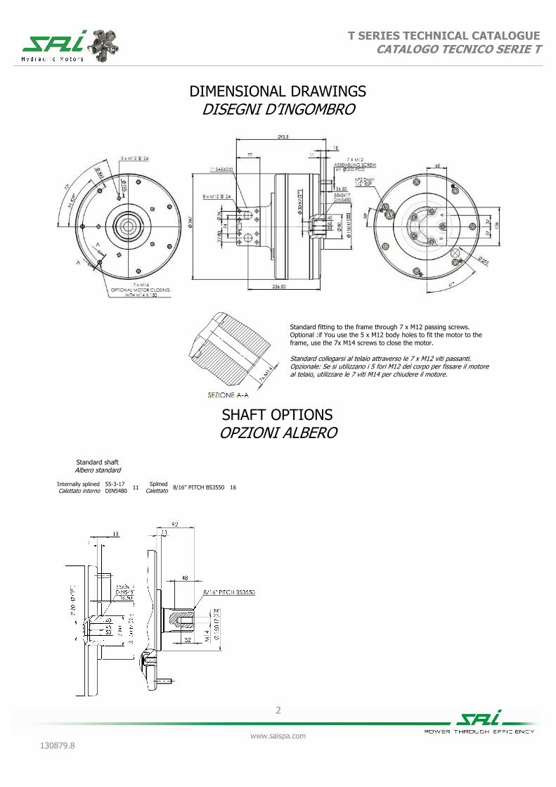
Standard fitting to the frame through 7 x M12 passing screws. Optional :if You use the 5 x M12 body holes to fit the motor to the frame, use the 7x M14 screws to close the motor. Standard collegarsi al telaio attraverso le 7 x M12 viti passanti. Opzionale: Se si utilizzano i 5 fori M12 del corpo per fissare il motore al telaio, utilizzare le 7 viti M14 per chiudere il motore.

3
www.saispa.com 130879.8
T SERIES TECHNICAL CATALOGUE CATALOGO TECNICO SERIE T
SPLINE DATA CALETTATURE
55-3-17 DIN5480
d0 Ø 51,000
d1 Ø 55,000 + 0,740
H14 + 0
d2 Ø 49,000 + 0,160
H11 + 0
A Ø 5,250
dA Ø 43,807
H11
d3 Ø 54,400 + 0,210
h11 + 0
d4 Ø 48,400 - 0
h14 - 0,620
B Ø 6,000
dB Ø 60,873 f8
BS 3550 17Z PITCH 8/16”
A Ø 56.410 + 0
- 0.15
B Ø 53.970
C Ø 50.060 + 0
- 0.48
D + 0.05
0
E Ø 6.090
Ø 62.800
GRAPHS GRAFICI
UNIT DISPLACEMENT - CILINDRATA UNITÀ L10 LIFETIME - VITA L10
PRES
SURE
- PR
ESSI
ON
E (b
ar)
PISTON DIAMETER - DIAMETRO PISTONE (Ø mm)
HO
UR
S -
ORE
UNIT SPEED - VELOCITÀ DELL’UNITÀ (rpm)
100 bar
35 40 45 50 55 60
0 200 400 600 800 1000 1200 1400
270
35
600
52
100
200
500
1.000
2.000
5.000 10.000 20.000 50.000
100.000 200.000 500.000
1.000.000
350
40
500
47
700
56
Bearing lifetime has been estimated according to L10 (according to ISO 281:1990). Please contact the SAI Technical Department for other graphs relating to this product.
La durata è stata calcolata in accordo con la formula L10 (secondo ISO 281:1990). Vi preghiamo di contattare l’Ufficio Tecnico SAI per altri grafici relativi a questo prodotto.
800
60

4
www.saispa.com 130879.8
T SERIES TECHNICAL CATALOGUE CATALOGO TECNICO SERIE T
ORDER CODES CODICI D’ORDINE
Example Esempio TF2.5 500 16G D40 (standard) (options: FKM seals and anti-clockwise sense of rotation) (opzioni: tenute in FKM e direzione d'uscita in rotazione anti-oraria)
TF2.5 500 16GV D40L
1 Displacement see table 1 Cilindrata vedere tabella
2 Shaft options
16 = Male 8/16 PITCH BS3550 2 Opzioni albero
16 = Maschio 8/16 PITCH BS3550
11 = Female 55-3-17 DIN 5480 11 = Femmina 55-3-17 DIN 5480
3 Other options V = FKM seals
3 Altre opzioni V = FKM seals
I = 3 bar pressure relief valve I = valvola di sfiato 3 bar 4 Distributor see distributor catalogue 4 Distributore vedere catalogo distributori
5 Distributor options
K = preparation for tachometer
5 Opzioni distributore
K = predisposizione contagiri
J = with tachometer J = con contagiri
6
Direction of rota-tion (viewed from the output side) with flow in port A, out in port B.
No code = clockwise rotation
6
Direzione d'uscita (visto dal lato d'uscita) con portata in ingres-so in port A, uscita in
Nessun codice = rotazione oraria
L = anti-clockwise rotation L = rotazione anti-oraria
7 Distributor cover
orientation
No code = position 1
Orientamento co-perchio distributo-re
Nessun codice = posizione 1
DM3 = position 2 DM3 = posizione 2 DM4 = position 3 DM4 = posizione 3
1 2 3 4 5 6
TF2.5 + + + G + + D40B + +
+ 7

��
��������������� �� ��� � � � � � � � � � � � � � � � � �
��������������������� ������� �����������������
��������������������������������������������
� ����� � ����� � ������ � ������ �
�� �!������������������"���!#� � ��$�� � ��%�� � �$��� � �%%%�� �
&������������ �!��������'���
"��#� ((��
�%��
�$��
$��)����**�� � � �
+��,��"��#� � �$�� � �$�� � �$�� � �$�� �
&����+��������� ��
"-��.��#� � �/(��� � ��/%(�� � ��/�$�� � ��/(��� �&�������������&���� ������� �������
".��#� � ( �� � ( �� � ( �� � �� �� �0��������������� �����0��,������ ���
".��#� � (� �� � (� �� � (� �� � ( �� �0��������������0��,�������
",1#� %% ���� %% ���� � %% ���� %% ���� �0���2���������&���� �����������
"���#� � 3 �� � �� �� � �� �� � � �� �4����5�������� �����6���� ��������
"���#� � � �� � 3 �� � 3 �� � $� �� �4����5����������)�������������*7��
",*#� �% � ���� �� 6�����������8�
"�#� (�0��������������!� ���5� �� &�����5���������
6���� ������*������ ����%��".��#�
������ ��
�� )������.����������� ����"9&#�
:% ������ ��
���� � ������0���������������������������%��
������,�
�� �������� ����������.���� ;� ������ ��
��� �������-<��+�
����&���� �����!���*����,��*������ ����7 ���.��7������������*��7��.�����*������������������������� ���������7������.�����*�/��������������7��+)=���7�����>������������
����?��������������� ��������������!��!���������������������������!�������� ���������0��� ���������!�������� ���������������������������@A����������+)=��
�%�����7�*7�������*������ ����������������7��+)=���7�����>�����������
�%��0��������������B����!������������������������@A����������+)=��
�������7�*7������� ���������������������7��+)=���7�����>�����������
����0���!����5�������� ���**��������������@A����������+)=��
=-+�)??)�=<-�-<��+�'������ ��������*��
"-�#�� �$�/ C$�3/ ������
��$/ C3�$/ ������ + **������.����8����
6% � �%����&����������**��!����� *���� ����� 4����� **�������

%�
��������������� �� ��� � � � � � � � � � � � � � � � � �
��������������������� ������� �����������������
>=6�-+=<-)?�>D)1=-E+��>=+�E-=�>@=-E<6'D<�
+F)���<0�=<-+�<0G=<-=�)?'�D<�

��
��������������� �� ��� � � � � � � � � � � � � � � � � �
��������������������� ������� �����������������
+0?=-��>)�)�&)?���)�AD��
ED)0F+�ED)�=&=�
A-=��>=+0?)&�6�-��:�&=?=->D)�)�A-=�H� ?� �?=���=6��:�4=�)�?� �
0D�+
+AD��:�0D
�++=<-���.����
0=+�<-�>=)6���D�:�>=)6��D<�0=+�<-���I�����
F<AD+�:�<D�
�
A-=��+0��>�:�4�?<&=�H�>�??@A-=�H�������
��������������������������(�������������������(�������������������������������������������������������������$��
� �
�$�
�� � �
� �
�%�
'�����*����������7���.�������������������*���?� �������*���=+<�%��J��� ���0������������7��+)=���7�����>��������������7���*���7���������*����7������ ���
?��� ��������� ��������K����������������������������� ���?� �������=+<�%��J��� ���4�����*7�����������������@A����������+)=�����������*������������!����� �����������
�% �
$��
��:�:�3�>=-�(� ��
� � I���/ � �
��� I���/ �;� /3( �
F�(��;� �
�%� I�(�/ �;� /�$ �
F����;� �
)� I��/%� � �
�)� I�(�/� 3���
F����
��� I��(/( ��;� /%� �
7���;� �
�(� I�(�/( �:� �
7�(�:� /$% �
'� I�$/ � �
�'� I�$ /�3���� ���
$ �
((�
����������������������������������������������������������������������������������������������������������������� ����������� ��������% ��������� �������( ���������� ��������$ ��������3 ��������� �
3�� �
� � ���� �
3�� �
�� �
��� �
3� �

(�
��������������� �� ��� � � � � � � � � � � � � � � � � �
��������������������� ������� �����������������
<D>�D�&<>�+�&<>=&=�>@<D>=-��
�������� �
������� �
������� ��E�>� 3� ������������ �
������J��L6���������������:�,��������������������� �
��2���J���� �������L6�������2�����M �����������2��������:������� � �
������� ��E4�>� 3?�
����������������� ������.��������� �������� ������ !��������.���������
%���!� �"���"����4� N� �L6�������
%��� ��"�#�"����4� N� �L6�������
=� N� ���.�������� ����������!��!�� =� N� !��!���������������.���
��
�� ����"��"$� "��%��"���!�����������7�� �� �����������7������������)/� ���������'��
-���� N� �,������������
��
�� �#�"����&'�������!�������������M ��������������������*���:���������)/� ������������'��������
-��� ������ N� ���2����������
?� N� ����:�,���������������� ?� N� ���2��������:����������
(������ �('�" ��")� �
" �������"����������������
-���� N� ���������$�
� ���������"��"%�� �!�"����� �('�"% ����������������
-��� ������ N� ���2������
>6�� N� �������%� >6�� N� ���2����%�>6$� N� ��������� >6$� N� ���2������
�� � � � � � %� � � � �� � (�
������;� �� ;� �� ;� E� ;� �� ;�>� 3�;� �� ;� ��
1
www.saispa.com 130887.12
T SERIES TECHNICAL CATALOGUE CATALOGO TECNICO SERIE T
TD1.5
240 60 (2) 340 85 (2) 400 100 (2)
Equivalent displacement ⁽¹⁾ [cc/rev]
241 60 341 85 405 101
Cilindrata equivalente ⁽¹⁾ Bore
[mm]
37 44 48
Alesaggio Stroke
[mm]
32 8 32 8 32 8
Corsa Specific torque
[Nm/bar]
3,82 0,95 5,43 1,35 6,45 1,60
Coppia specifica Continuous pressure
[bar]
350
Pressione in continuo Peak pressure ⁽³⁾
[bar]
450 450
Pressione di picco ⁽³⁾ Peak power ⁽⁴⁾
[kW]
110 80 110 80 110 80
Potenza di picco ⁽⁴⁾ Continuous speed
[rpm]
700 1800 700 1800 650 1500
Velocità in continuo Maximum speed
[rpm]
900 2300 900 2300 800 1800
Velocità massima Approximative weight
[kg] 55 unit Motor oil capacity
[l] 0,8 Peso approssimativo unità Capacità olio motore
Maximum casing pressure [bar]
5 continuous
Admissible temperatures [°C]
-20 minimum
continuo minimo
Pressione massima in carcassa 15 peak
Temperature ammissibili +80 maximum
picco massimo
Override change displacement pilot pressure range
[bar] 15 ÷ 40
Override change displ. pilot oil capacity
[cm3] 1,5
Campo di pressione di cambio cilindrata override
Capacità olio di cambio cil. override
Bolt torque setting [Nm] 116÷143
coarse 121÷150
fine Suggested bolt type M12 12.9
Coppia serraggio viti grosso fine Viti suggerite NOTES
(1) For different displacements, please contact the SAI Commercial Department. (1) Per cilindrate differenti, contattare l’Ufficio Commerciale SAI. (2) Minimum displacement can be 0cc for each configuration, please contact the SAI Technical Department. (2) La minima cilindrata può essere 0cc per ogni configurazione, contattare l’Ufficio Tecnico SAI. (3) For higher peak pressures please contact the SAI Technical Department. (3) Per pressioni di picco maggiori contattare l’Ufficio Tecnico SAI. (4) For higher peak powers please contact the SAI Technical Department.
(4) Per Potenze di picco maggiori contattare l'Ufficio Tecnico SAI.
400
Zero displacement available on request
Cilindrata zero disponibile su richiesta
2
www.saispa.com 130887.12
T SERIES TECHNICAL CATALOGUE CATALOGO TECNICO SERIE T
DIMENSIONAL DRAWINGS DISEGNI D’INGOMBRO
SHAFT OPTIONS OPZIONI ALBERO
Internally splined Calettato interno
40-3-12 DIN5480 9
Standard shaft Albero standard
Splined Calettato 46 UNI 221 1

3
www.saispa.com 130887.12
T SERIES TECHNICAL CATALOGUE CATALOGO TECNICO SERIE T
SPLINE DATA CALETTATURE
46 UNI 221 (8-46-54 DIN 5463)
d1 Ø 46,000 + 0,025
H7 + 0
d2 Ø 54,000 + 0,460
H13 + 0
A Ø 9,000 + 0,035
F8 + 0,013
d3 Ø 46,000 - 0,009
g6 - 0,025
d4 Ø 54,000 - 0,100
d11 - 0,290
Ø 9,000 - 0,013
f7 - 0,028
B
40-3-12 DIN 5480
d0 Ø 36,000
d1 Ø 40,000 + 0,620
H14 + 0
d2 Ø 34,000 + 0,160
H11 + 0
A Ø 5,250
dA Ø 28,964
H11
d3 Ø 39,400 - 0
h11 - 0,160
d4 Ø 33,400 - 0
h14 - 0,620
B Ø 6,000
dB Ø 45,989 f8
T SERIES CATALOGUE CATALOGO TECNICO SERIE T
4
www.saispa.com 130887.11
GRAPHS GRAFICI
UNIT DISPLACEMENT - CILINDRATA UNITÀ L10 LIFETIME - VITA L10
PRES
SURE
- PR
ESSI
ON
E (b
ar)
PISTON DIAMETER - DIAMETRO PISTONE (Ø mm)
HO
UR
S -
ORE
UNIT SPEED - VELOCITÀ DELL’UNITÀ (rpm)
100 bar
28 33 38 43 48
0 200 400 600 800 1000 1200 1400
130
28
340
44
100
200
500
1.000
2.000
5.000 10.000 20.000 50.000
100.000 200.000 500.000
1.000.000
210
35
240
37
400
48
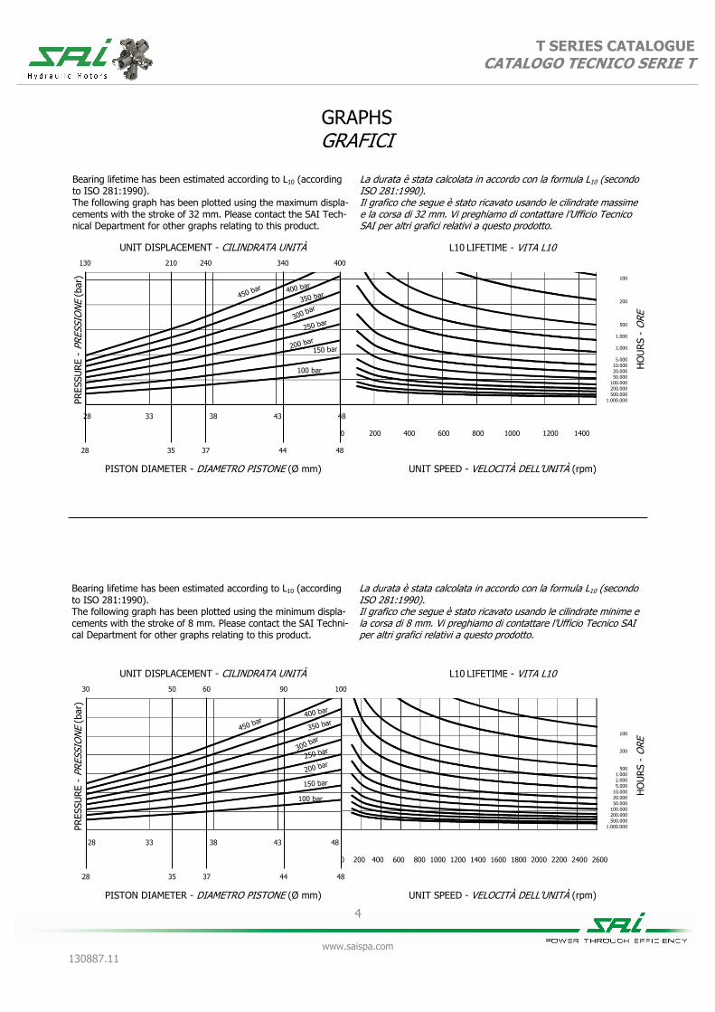
Bearing lifetime has been estimated according to L10 (according to ISO 281:1990). The following graph has been plotted using the maximum displa-cements with the stroke of 32 mm. Please contact the SAI Tech-nical Department for other graphs relating to this product.
La durata è stata calcolata in accordo con la formula L10 (secondo ISO 281:1990). Il grafico che segue è stato ricavato usando le cilindrate massime e la corsa di 32 mm. Vi preghiamo di contattare l’Ufficio Tecnico SAI per altri grafici relativi a questo prodotto.
UNIT DISPLACEMENT - CILINDRATA UNITÀ L10 LIFETIME - VITA L10
PRES
SURE
- PR
ESSI
ON
E (b
ar)
PISTON DIAMETER - DIAMETRO PISTONE (Ø mm)
HO
UR
S -
ORE
UNIT SPEED - VELOCITÀ DELL’UNITÀ (rpm)
28 33 38 43 48
0 200 400 600 800 1000 1200 1400 1600 1800 2000 2200 2400 2600
100
200
500 1.000 2.000 5.000
10.000 20.000 50.000
100.000 200.000 500.000
1.000.000
Bearing lifetime has been estimated according to L10 (according to ISO 281:1990). The following graph has been plotted using the minimum displa-cements with the stroke of 8 mm. Please contact the SAI Techni-cal Department for other graphs relating to this product.
La durata è stata calcolata in accordo con la formula L10 (secondo ISO 281:1990). Il grafico che segue è stato ricavato usando le cilindrate minime e la corsa di 8 mm. Vi preghiamo di contattare l’Ufficio Tecnico SAI per altri grafici relativi a questo prodotto.
100 bar
30
28
90
44
50
35
60
37
100
48

5
www.saispa.com 130887.12
T SERIES TECHNICAL CATALOGUE CATALOGO TECNICO SERIE T
ORDER CODES CODICI D’ORDINE
Example Esempio TD1.5 220 50 1G D47D (standard)
(options: FKM seals, electrical pilot displacement, no slow change and anti-clockwise sense of rotation)
(opzioni: tenute in FKM, pilotaggio cilindrata elettrico, no cambio lento e direzio-ne d'uscita in rotazione anti-oraria)
TD1.5 220 50 1GV D47DE NS L
1 Displacement see table 1 Cilindrata vedere tabella
2 Shaft options
1 = male 46 UNI 221 2 Opzioni albero
1 = maschio 46 UNI 221 9 = female 40-3-12 DIN 5480 9 = femmina 40-3-12 DIN 5480
3 Other options V = FKM seals
3 Altre opzioni V = FKM seals
I = 3 bar pressure relief valve I = valvola di sfiato 3 bar
4 Distributor
D47D = Hydraulic pilot displacement(standard)
4 Distributore D47D = Pilotaggio cilindrata idraulico
(standard)
D47DE = Electrical pilot displacement (12-24V) D47DE = Pilotaggio cilindrata elettrico
(12-24V)
5 Distributor options
nocode = slow change
5 Opzioni distributore
nessun-codice = cambio lento
NS = no slow change NS = no cambio lento
6
Direction of rota-tion (viewed from the output side) with input flow in port A, output in B.
No code = clockwise rotation 6
Direzione d'uscita (visto dal lato d'uscita) con portata in ingres-so in porta A, uscita in B.
Nessun codice = rotazione oraria
L = anti-clockwise rotation L = rotazione anti-oraria
1 2 3 4 5 6
TD1.5 + + + G + + D47D + +
1
www.saispa.com 130933.4
T SERIES TECHNICAL CATALOGUE CATALOGO TECNICO SERIE T
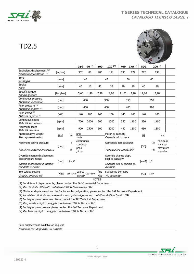
TD2.5
350 90 (2) 500 120 (2) 700 175 (2) 800 200 (2)
Equivalent displacement ⁽¹⁾ [cc/rev]
352 88 486 121 690 172 792 198
Cilindrata equivalente ⁽¹⁾ Bore
[mm]
40 47 56 60
Alesaggio Stroke
[mm]
40 10 40 10 40 10 40 10
Corsa Specific torque
[Nm/bar]
5,60 1,40 7,70 1,90 11,00 2,70 12,60 3,20
Coppia specifica Continuous pressure
[bar]
400 350 350 350
Pressione in continuo Peak pressure ⁽³⁾
[bar]
450 400 400 400
Pressione di picco ⁽³⁾ Peak power ⁽⁴⁾
[kW]
140 100 140 100 140 100 140 100
Potenza di picco ⁽⁴⁾ Continuous speed
[rpm]
700 2000 500 1700 350 1400 350 1400
Velocità in continuo Maximum speed
[rpm]
900 2500 600 2200 450 1800 450
Velocità massima Approximative weight
[kg] 90 unit Motor oil capacity
[l] 0,8 Peso approssimativo unità Capacità olio motore
Maximum casing pressure [bar]
5 continuous
Admissible temperatures [°C]
-20 minimum
continuo minimo
Pressione massima in carcassa 15 peak
Temperature ammissibili +80 maximum
picco massimo
Override change displacement pilot pressure range
[bar] 15 ÷ 40
Override change displ. pilot oil capacity
[cm3] 1,5
Campo di pressione di cambio cilindrata override
Capacità olio di cambio cil. override
Bolt torque setting [Nm] 116÷143
coarse 121÷150
fine Suggested bolt type M12 12.9
Coppia serraggio viti grosso fine Viti suggerite NOTES
(1) For different displacements, please contact the SAI Commercial Department. (1) Per cilindrate differenti, contattare l’Ufficio Commerciale SAI. (2) Minimum displacement can be 0cc for each configuration, please contact the SAI Technical Department. (2) La minima cilindrata può essere 0cc per ogni configurazione, contattare l’Ufficio Tecnico SAI. (3) For higher peak pressures please contact the SAI Technical Department. (3) Per pressioni di picco maggiori contattare l’Ufficio Tecnico SAI. (4) For higher peak powers please contact the SAI Technical Department.
(4) Per Potenze di picco maggiori contattare l'Ufficio Tecnico SAI.
1800
Zero displacement available on request
Cilindrata zero disponibile su richiesta

2
www.saispa.com 130933.4
T SERIES TECHNICAL CATALOGUE CATALOGO TECNICO SERIE T
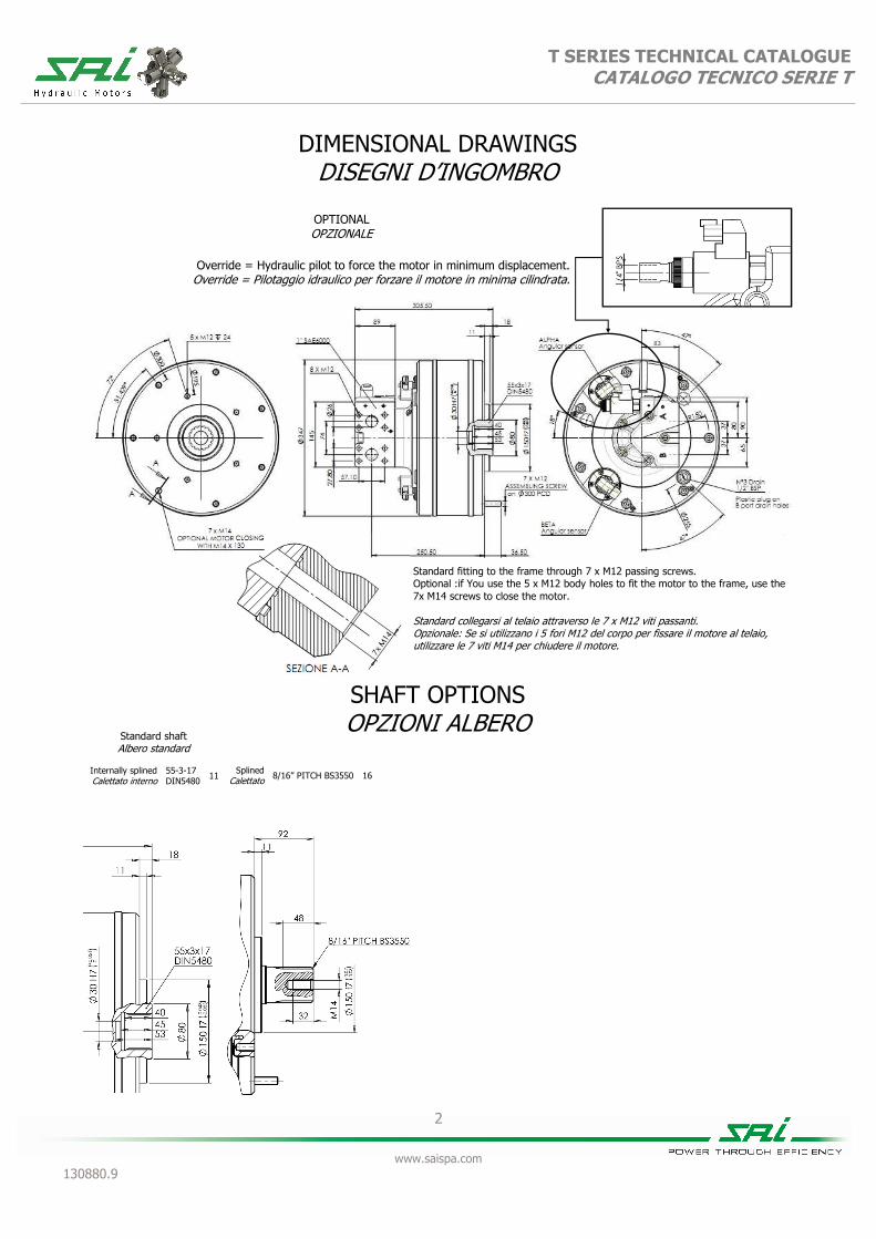
DIMENSIONAL DRAWINGS DISEGNI D’INGOMBRO
SHAFT OPTIONS OPZIONI ALBERO
Internally splined Calettato interno
55-3-17 DIN5480 11
Standard shaft Albero standard
Splined Calettato 8/16” PITCH BS3550 16
Standard fitting to the frame through 7 x M12 passing screws. Optional :if You use the 5 x M12 body holes to fit the motor to the frame, use the 7x M14 screws to close the motor. Standard collegarsi al telaio attraverso le 7 x M12 viti passanti. Opzionale: Se si utilizzano i 5 fori M12 del corpo per fissare il motore al telaio, utilizzare le 7 viti M14 per chiudere il motore.

3
www.saispa.com 130933.4
T SERIES TECHNICAL CATALOGUE CATALOGO TECNICO SERIE T
SPLINE DATA CALETTATURE
55-3-17 DIN5480
d0 Ø 51,000
d1 Ø 55,000 + 0,740
H14 + 0
d2 Ø 49,000 + 0,160
H11 + 0
A Ø 5,250
dA Ø 43,807
H11
d3 Ø 54,400 + 0,210
h11 + 0
d4 Ø 48,400 - 0
h14 - 0,620
B Ø 6,000
dB Ø 60,873 f8
BS 3550 17Z PITCH 8/16”
A Ø 56.410 + 0
- 0.15
B Ø 53.970
C Ø 50.060 + 0
- 0.48
D + 0.05
0
E Ø 6.090
Ø 62.800

T SERIES CATALOGUE CATALOGO TECNICO SERIE T
4
www.saispa.com 130933.4
GRAPHS GRAFICI
Bearing lifetime has been estimated according to L10 (according to ISO 281:1990). The following graph has been plotted using the maximum displa-cements with the stroke of 40 mm. Please contact the SAI Tech-nical Department for other graphs relating to this product.
La durata è stata calcolata in accordo con la formula L10 (secondo ISO 281:1990). Il grafico che segue è stato ricavato usando le cilindrate massime e la corsa di 40 mm. Vi preghiamo di contattare l’Ufficio Tecnico SAI per altri grafici relativi a questo prodotto.
Bearing lifetime has been estimated according to L10 (according to ISO 281:1990). The following graph has been plotted using the minimum displa-cements with the stroke of 10 mm. Please contact the SAI Tech-nical Department for other graphs relating to this product.
La durata è stata calcolata in accordo con la formula L10 (secondo ISO 281:1990). Il grafico che segue è stato ricavato usando le cilindrate minime e la corsa di 10 mm. Vi preghiamo di contattare l’Ufficio Tecnico SAI per altri grafici relativi a questo prodotto.
UNIT DISPLACEMENT - CILINDRATA UNITÀ L10 LIFETIME - VITA L10
PRES
SURE
- PR
ESSI
ON
E (b
ar)
PISTON DIAMETER - DIAMETRO PISTONE (Ø mm)
HO
UR
S -
ORE
UNIT SPEED - VELOCITÀ DELL’UNITÀ (rpm)
100 bar
35 40 45 50 55 60
0 200 400 600 800 1000 1200 1400
270
35
600
52
100
200
500
1.000
2.000
5.000 10.000 20.000 50.000
100.000 200.000 500.000
1.000.000
350
40
500
47
700
56
800
60
UNIT DISPLACEMENT - CILINDRATA UNITÀ L10 LIFETIME - VITA L10
PRES
SURE
- PR
ESSI
ON
E (b
ar)
PISTON DIAMETER - DIAMETRO PISTONE (Ø mm)
HO
UR
S -
ORE
UNIT SPEED - VELOCITÀ DELL’UNITÀ (rpm)
100 bar
35 40 45 50 55 60
0 200 400 600 800 1000 1200 1400
70
35
150
52
100
200
500 1.000 2.000 5.000
10.000 20.000 50.000
100.000 200.000 500.000
1.000.000
90
40
120
47
175
56
200
60
5
www.saispa.com 130933.4
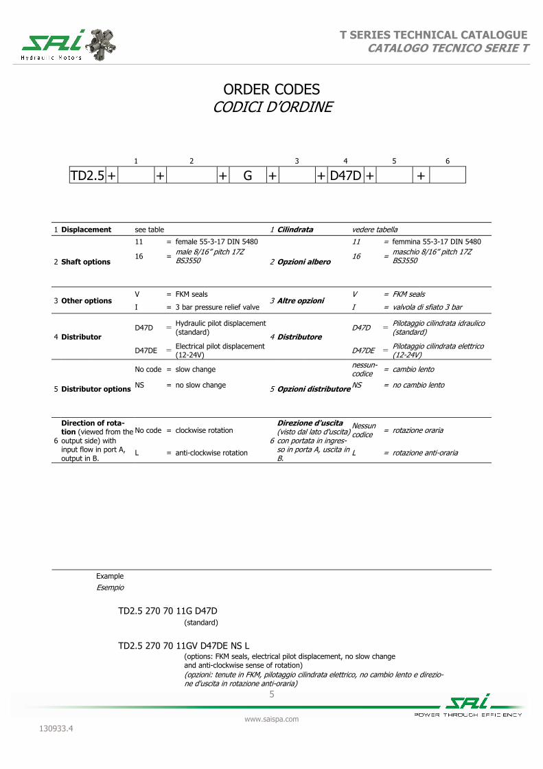
T SERIES TECHNICAL CATALOGUE CATALOGO TECNICO SERIE T
ORDER CODES CODICI D’ORDINE
1 2 3 4 5
TD2.5 + + + G + + D47D +
+ 6
1 Displacement see table 1 Cilindrata vedere tabella
2 Shaft options
11 = female 55-3-17 DIN 5480
2 Opzioni albero
11 = femmina 55-3-17 DIN 5480
16 = male 8/16” pitch 17Z BS3550 16 = maschio 8/16” pitch 17Z
BS3550
3 Other options V = FKM seals
3 Altre opzioni V = FKM seals
I = 3 bar pressure relief valve I = valvola di sfiato 3 bar
4 Distributor
D47D = Hydraulic pilot displacement(standard)
4 Distributore D47D = Pilotaggio cilindrata idraulico
(standard)
D47DE = Electrical pilot displacement (12-24V) D47DE =
5 Distributor options
No code = slow change
5 Opzioni distributore
nessun-codice = cambio lento
NS = no slow change NS = no cambio lento
6
Direction of rota-tion (viewed from the output side) with input flow in port A, output in B.
No code = clockwise rotation 6
Direzione d'uscita (visto dal lato d'uscita) con portata in ingres-so in porta A, uscita in B.
Nessun codice = rotazione oraria
L = anti-clockwise rotation L = rotazione anti-oraria
Pilotaggio cilindrata elettrico (12-24V)
Example Esempio TD2.5 270 70 11G D47D (standard)
(options: FKM seals, electrical pilot displacement, no slow change and anti-clockwise sense of rotation)
(opzioni: tenute in FKM, pilotaggio cilindrata elettrico, no cambio lento e direzio-ne d'uscita in rotazione anti-oraria)
TD2.5 270 70 11GV D47DE NS L

1
www.saispa.com 130933.4
T SERIES TECHNICAL CATALOGUE CATALOGO TECNICO SERIE T
TD3.5
450 110 600 150 800 200 1000 250 1100 280 1200 300
Equivalent displacement [cc/rev] 445 111 596 149 832 208 965 241 1108 277 1222 305
Cilindrata equivalente Bore
[mm] 38 44 52 56 60 63 Alesaggio Stroke
[mm] 56 14 56 14 56 14 56 14 56 14 56 14 Corsa Specific torque
[Nm/bar] 7,08 1,77 9,48 2,37 13,24 3,31 15,36 3,83 17,63 4,41 19,45 4,85 Coppia specifica Continuous pressure
[bar] 400 400 400 400 400 400 400 400 400 400 350 350 Pressione in continuo Peak pressure ⁽ 1
⁾ [bar] 450 450 450 450 450 450 450 450 450 450 400 400
Pressione di picco ⁽ 1 ) Peak power
[kW] 220 180 220 180 220 180 220 180 220 180 220 180 Potenza di picco Continuous speed
[rpm] 700 1400 700 1400 550 1400 550 1400 500 1300 500 1300 Velocità in continuo Maximum speed
[rpm] 900 1800 800 1800 700 1800 700 1800 650 1600 650 1600 Velocità massima Approximative weight
[kg] 120 unit Motor oil capacity
[l] 4 Peso approssimativo unità Capacità olio motore
Maximum casing pressure (2) [bar]
5 continuous
Admissible temperatures [°C]
-20 minimum
continuo minimo Pressione massima in carcassa (2) 15
peak Temperature ammissibili +80
maximum picco massimo
Bolt torque setting [Nm] 561-697
coarse fine Suggested bolt type M20 12.9
Coppia serraggio viti grosso fine Viti suggerite NOTES
(1) Continuous or average working pressure should be chosen depending on the bearing lifetime. For lifetime calculation of the motor bearings, please contact the SAI Technical Department.
(1) La pressione continua o media di lavoro va determinata in funzione della vita dei cuscinetti. Per un calcolo di vita dei cuscinetti del motore contattare l’Ufficio Tecnico SAI.
(2) For higher casing pressure please contact the SAI Technical Department.
(2) Per pressioni più elevate in carcassa contattare l’Ufficio Tecnico SAI.
586-736
Zero displacement available on request
Cilindrata zero disponibile su richiesta

2
www.saispa.com 130933.4
T SERIES TECHNICAL CATALOGUE CATALOGO TECNICO SERIE T
DIMENSIONAL DRAWINGS DISEGNI D’INGOMBRO
SHAFT OPTIONS OPZIONI ALBERO
SPLINE DATA CALETTATURE
55-3-17 DIN5480
d0 Ø 51,000
d1 Ø 55,000 + 0,740
H14 + 0
d2 Ø 49,000 + 0,160
H11 + 0
A Ø 5,250
dA Ø 43,807
H11
d3 Ø 54,400 + 0,210
h11 + 0
d4 Ø 48,400 - 0
h14 - 0,620
B Ø 6,000
dB Ø 60,873 f8
Ø39
9

T SERIES CATALOGUE CATALOGO TECNICO SERIE T
3
www.saispa.com 130933.3
GRAPHS GRAFICI
Bearing lifetime has been estimated according to L10 (according to ISO 281:1990). The following graph has been plotted using the maximum displa-cements with the stroke of 40 mm. Please contact the SAI Tech-nical Department for other graphs relating to this product.
La durata è stata calcolata in accordo con la formula L10 (secondo ISO 281:1990). Il grafico che segue è stato ricavato usando le cilindrate massime e la corsa di 40 mm. Vi preghiamo di contattare l’Ufficio Tecnico SAI per altri grafici relativi a questo prodotto.
Bearing lifetime has been estimated according to L10 (according to ISO 281:1990). The following graph has been plotted using the minimum displa-cements with the stroke of 10 mm. Please contact the SAI Tech-nical Department for other graphs relating to this product.
La durata è stata calcolata in accordo con la formula L10 (secondo ISO 281:1990). Il grafico che segue è stato ricavato usando le cilindrate minime e la corsa di 10 mm. Vi preghiamo di contattare l’Ufficio Tecnico SAI per altri grafici relativi a questo prodotto.
UNIT DISPLACEMENT - CILINDRATA UNITÀ L10 LIFETIME - VITA L10
PRES
SURE
- PR
ESSI
ON
E (b
ar)
PISTON DIAMETER - DIAMETRO PISTONE (Ø mm)
HO
UR
S -
ORE
UNIT SPEED - VELOCITÀ DELL’UNITÀ (rpm)
100 bar
38 43 48 53 58 63
0 200 400 600 800 1000 1200 1400
1000
56
100
200
500
1.000
2.000
5.000 10.000 20.000 50.000
100.000 200.000 500.000
1.000.000
800
52
1100
60
1200
63
UNIT DISPLACEMENT - CILINDRATA UNITÀ L10 LIFETIME - VITA L10
PRES
SURE
- PR
ESSI
ON
E (b
ar)
PISTON DIAMETER - DIAMETRO PISTONE (Ø mm)
HO
UR
S -
ORE
UNIT SPEED - VELOCITÀ DELL’UNITÀ (rpm)
100 bar
38 43 48 53 58 63
0 200 400 600 800 1000 1200 1400 1600 1800 2000
250
56
100
200
500
1.000
2.000
5.000 10.000 20.000 50.000
100.000 200.000 500.000
1.000.000
200
52
280
60
300
63

4
www.saispa.com 130933.4
T SERIES TECHNICAL CATALOGUE CATALOGO TECNICO SERIE T
ORDER CODES CODICI D’ORDINE
Example Esempio TD3.5 800-200 9G D907D (standard) (options: FKM seals and anti-clockwise sense of rotation) (opzioni: tenute in FKM e direzione d'uscita in rotazione anti-oraria)
TD3.5 800-200 9GV D907DL
1 2 3 4 5
TD3.5 + + 9 + G + + D907D + +
1 Displacement see table 1 Cilindrata vedere tabella
3 Other options V = FKM seals
3 Altre opzioni V = FKM seals
I = 3 bar pressure relief valve I = valvola di sfiato 3 bar
4 Distributor
D907D = Hydraulic pilot displacement(standard)
4 Distributore D907D = Pilotaggio cilindrata idraulico
(standard)
D907DE = Electrical pilot displacement (12-24V) D907DE = Pilotaggio cilindrata elettrico
(12-24V)
5 Distributor options
nocode = slow change
5 Opzioni distributore
nessun-codice = cambio lento
NS = no slow change NS = no cambio lento
6
Direction of rota-tion (viewed from the output side) with input flow in port A, output in B.
No code = clockwise rotation 6
Direzione d'uscita (visto dal lato d'uscita) con portata in ingres-so in porta A, uscita in B.
Nessun codice = rotazione oraria
L = anti-clockwise rotation L = rotazione anti-oraria

1
www.saispa.com 130881.8
T SERIES TECHNICAL CATALOGUE CATALOGO TECNICO SERIE T
TV1.5
240 60 (2) 340 85 (2) 400 100 (2)
Equivalent displacement ⁽¹⁾ [cc/rev]
241 60 341 85 405 101
Cilindrata equivalente ⁽¹⁾ Bore
[mm]
37 44 48
Alesaggio Stroke
[mm]
32 8 32 8 32 8
Corsa Specific torque
[Nm/bar]
3,82 0,95 5,43 1,35 6,45 1,60
Coppia specifica Continuous pressure
[bar]
350
Pressione in continuo Peak pressure ⁽³⁾
[bar]
450 450
Pressione di picco ⁽³⁾ Peak power ⁽⁴⁾
[kW]
110 80 110 80 110 80
Potenza di picco ⁽⁴⁾ Continuous speed
[rpm]
700 1800 700 1800 650 1500
Velocità in continuo Maximum speed
[rpm]
900 2300 900 2300 800 1800
Velocità massima Approximative weight
[kg] 55 unit Motor oil capacity
[l] 0,8 Peso approssimativo unità Capacità olio motore
Maximum casing pressure [bar]
5 continuous
Admissible temperatures [°C]
-20 minimum
continuo minimo
Pressione massima in carcassa 15 peak
Temperature ammissibili +80 maximum
picco massimo
Override change displacement pilot pressure range
[bar] 15 ÷ 40
Override change displ. pilot oil capacity
[cm3] 1,5
Campo di pressione di cambio cilindrata override
Capacità olio di cambio cil. override
Bolt torque setting [Nm] 116÷143
coarse 121÷150
fine Suggested bolt type M12 12.9
Coppia serraggio viti grosso fine Viti suggerite NOTES
(1) For different displacements, please contact the SAI Commercial Department. (1) Per cilindrate differenti, contattare l’Ufficio Commerciale SAI. (2) Minimum displacement can be 0cc for each configuration, please contact the SAI Technical Department. (2) La minima cilindrata può essere 0cc per ogni configurazione, contattare l’Ufficio Tecnico SAI. (3) For higher peak pressures please contact the SAI Technical Department. (3) Per pressioni di picco maggiori contattare l’Ufficio Tecnico SAI. (4) For higher peak powers please contact the SAI Technical Department.
(4) Per Potenze di picco maggiori contattare l'Ufficio Tecnico SAI.
400
Zero displacement available on request
Cilindrata zero disponibile su richiesta

2
www.saispa.com 130881.8
T SERIES TECHNICAL CATALOGUE CATALOGO TECNICO SERIE T
DIMENSIONAL DRAWINGS DISEGNI D’INGOMBRO
Override = Hydraulic pilot to force the motor in minimum displacement.Override = Pilotaggio idraulico per forzare il motore in minima cilindrata.
SHAFT OPTIONS OPZIONI ALBERO
Splined Calettato 46 UNI 221 1
Internally splined Calettato interno
40-3-12 DIN5480 9

3
www.saispa.com 130881.8
T SERIES TECHNICAL CATALOGUE CATALOGO TECNICO SERIE T
SPLINE DATA CALETTATURE
46 UNI 221 (8-46-54 DIN 5463)
d1 Ø 46,000 + 0,025
H7 + 0
d2 Ø 54,000 + 0,460
H13 + 0
A Ø 9,000 + 0,035
F8 + 0,013
d3 Ø 46,000 - 0,009
g6 - 0,025
d4 Ø 54,000 - 0,100
d11 - 0,290
Ø 9,000 - 0,013
f7 - 0,028
B
40-3-12 DIN 5480
d0 Ø 36,000
d1 Ø 40,000 + 0,620
H14 + 0
d2 Ø 34,000 + 0,160
H11 + 0
A Ø 5,250
dA Ø 28,964
H11
d3 Ø 39,400 - 0
h11 - 0,160
d4 Ø 33,400 - 0
h14 - 0,620
B Ø 6,000
dB Ø 45,989 f8

T SERIES CATALOGUE CATALOGO TECNICO SERIE T
4
www.saispa.com 130881.8
GRAPHS GRAFICI
UNIT DISPLACEMENT - CILINDRATA UNITÀ L10 LIFETIME - VITA L10
PRES
SURE
- PR
ESSI
ON
E (b
ar)
PISTON DIAMETER - DIAMETRO PISTONE (Ø mm)
HO
UR
S -
ORE
UNIT SPEED - VELOCITÀ DELL’UNITÀ (rpm)
100 bar
28 33 38 43 48
0 200 400 600 800 1000 1200 1400
130
28
340
44
100
200
500
1.000
2.000
5.000 10.000 20.000 50.000
100.000 200.000 500.000
1.000.000
210
35
240
37
400
48
Bearing lifetime has been estimated according to L10 (according to ISO 281:1990). The following graph has been plotted using the maximum displa-cements with the stroke of 32 mm. Please contact the SAI Tech-nical Department for other graphs relating to this product.
La durata è stata calcolata in accordo con la formula L10 (secondo ISO 281:1990). Il grafico che segue è stato ricavato usando le cilindrate massime e la corsa di 32 mm. Vi preghiamo di contattare l’Ufficio Tecnico SAI per altri grafici relativi a questo prodotto.
UNIT DISPLACEMENT - CILINDRATA UNITÀ L10 LIFETIME - VITA L10
PRES
SURE
- PR
ESSI
ON
E (b
ar)
PISTON DIAMETER - DIAMETRO PISTONE (Ø mm)
HO
UR
S -
ORE
UNIT SPEED - VELOCITÀ DELL’UNITÀ (rpm)
28 33 38 43 48
0 200 400 600 800 1000 1200 1400 1600 1800 2000 2200 2400 2600
100
200
500 1.000 2.000 5.000
10.000 20.000 50.000
100.000 200.000 500.000
1.000.000
Bearing lifetime has been estimated according to L10 (according to ISO 281:1990). The following graph has been plotted using the minimum displa-cements with the stroke of 8 mm. Please contact the SAI Techni-cal Department for other graphs relating to this product.
La durata è stata calcolata in accordo con la formula L10 (secondo ISO 281:1990). Il grafico che segue è stato ricavato usando le cilindrate minime e la corsa di 8 mm. Vi preghiamo di contattare l’Ufficio Tecnico SAI per altri grafici relativi a questo prodotto.
100 bar
30
28
90
44
50
35
60
37
100
48

5
www.saispa.com 130881.8
T SERIES TECHNICAL CATALOGUE CATALOGO TECNICO SERIE T
ORDER CODES CODICI D’ORDINE
Example
Esempio TV1.5 400-100 9G D47V (standard) (options: FKM seal and direction anti-clockwise of the rotation) (opzioni: tenute in FKM e direzione d’uscita in rotazione anti-oraria)
TV1.5 400-100 9GV D47VL
1 Displacement see table 1 Cilindrata vedere tabella
2 Shaft options 1 = male 46 UNI 221
2 Opzioni albero 1 = maschio 46 UNI 221
9 = female 40-3-12 DIN 5480 9 = femmina 40-3-12 DIN 5480
3 Other options V = FKM seals
3 Altre opzioni V = FKM seals
I = 3 bar pressure relief valve I = valvola di sfiato 3 bar
4
Direction of rota-tion (viewed from the output side) with flow in port A, out in port B.
No code = clockwise rotation 4
Direzione d'uscita (visto dal lato d'uscita) con portata in ingres-so in port A, uscita in port B.
Nessun codice = rotazione oraria
L = anti-clockwise rotation L = rotazione anti-oraria
5 Accessories
HU = Integrated speed sensor 5 Accessori
HU = Sensore di velocità integrato
OV = Override* OV = Override*
6 Sensor position No code = Position 1
6 Orientamento/
posizione dei sensori
Nessun codice = Posizione 1
Pos2 = Position 2 Pos2 = Posizione 2 Pos3 = Position 3 Pos3 = Posizione 3
1 2 3 4 5 6
TV1.5 + + + G + + D47V + + +
* Override = Hydraulic pilot to force the motor in minimum displa-cement.
* Override = Pilotaggio idraulico per forzare il motore in minima cilindrata.

1
www.saispa.com 130880.9
T SERIES TECHNICAL CATALOGUE CATALOGO TECNICO SERIE T
TV2.5
350 90 (2) 500 120 (2) 700 175 (2) 800 200 (2)
Equivalent displacement ⁽¹⁾ [cc/rev]
352 88 486 121 690 172 792 198
Cilindrata equivalente ⁽¹⁾ Bore
[mm]
40 47 56 60
Alesaggio Stroke
[mm]
40 10 40 10 40 10 40 10
Corsa Specific torque
[Nm/bar]
5,60 1,40 7,70 1,90 11,00 2,70 12,60 3,20
Coppia specifica Continuous pressure
[bar]
400 350 350 350
Pressione in continuo Peak pressure ⁽³⁾
[bar]
450 400 400 400
Pressione di picco ⁽³⁾ Peak power ⁽⁴⁾
[kW]
140 100 140 100 140 100 140 100
Potenza di picco ⁽⁴⁾ Continuous speed
[rpm]
700 2000 500 1700 350 1400 350 1400
Velocità in continuo Maximum speed
[rpm]
900 2500 600 2200 450 1800 450
Velocità massima Approximative weight
[kg] 90 unit Motor oil capacity
[l] 0,8 Peso approssimativo unità Capacità olio motore
Maximum casing pressure [bar]
5 continuous
Admissible temperatures [°C]
-20 minimum
continuo minimo
Pressione massima in carcassa 15 peak
Temperature ammissibili +80 maximum
picco massimo
Override change displacement pilot pressure range
[bar] 15 ÷ 40
Override change displ. pilot oil capacity
[cm3] 1,5
Campo di pressione di cambio cilindrata override
Capacità olio di cambio cil. override
Bolt torque setting [Nm] 116÷143
coarse 121÷150
fine Suggested bolt type M12 12.9
Coppia serraggio viti grosso fine Viti suggerite NOTES
(1) For different displacements, please contact the SAI Commercial Department. (1) Per cilindrate differenti, contattare l’Ufficio Commerciale SAI. (2) Minimum displacement can be 0cc for each configuration, please contact the SAI Technical Department. (2) La minima cilindrata può essere 0cc per ogni configurazione, contattare l’Ufficio Tecnico SAI. (3) For higher peak pressures please contact the SAI Technical Department. (3) Per pressioni di picco maggiori contattare l’Ufficio Tecnico SAI. (4) For higher peak powers please contact the SAI Technical Department.
(4) Per Potenze di picco maggiori contattare l'Ufficio Tecnico SAI.
1800
Zero displacement available on request
Cilindrata zero disponibile su richiesta
2
www.saispa.com 130880.9
T SERIES TECHNICAL CATALOGUE CATALOGO TECNICO SERIE T
DIMENSIONAL DRAWINGS DISEGNI D’INGOMBRO
Override = Hydraulic pilot to force the motor in minimum displacement. Override = Pilotaggio idraulico per forzare il motore in minima cilindrata.
OPTIONAL OPZIONALE
Splined Calettato 8/16” PITCH BS3550 16
Internally splined Calettato interno
55-3-17 DIN5480 11
Standard shaft Albero standard
SHAFT OPTIONS OPZIONI ALBERO
Standard fitting to the frame through 7 x M12 passing screws. Optional :if You use the 5 x M12 body holes to fit the motor to the frame, use the 7x M14 screws to close the motor. Standard collegarsi al telaio attraverso le 7 x M12 viti passanti. Opzionale: Se si utilizzano i 5 fori M12 del corpo per fissare il motore al telaio, utilizzare le 7 viti M14 per chiudere il motore.

3
www.saispa.com 130880.9
T SERIES TECHNICAL CATALOGUE CATALOGO TECNICO SERIE T
SPLINE DATA CALETTATURE
55-3-17 DIN5480
d0 Ø 51,000
d1 Ø 55,000 + 0,740
H14 + 0
d2 Ø 49,000 + 0,160
H11 + 0
A Ø 5,250
dA Ø 43,807
H11
d3 Ø 54,400 + 0,210
h11 + 0
d4 Ø 48,400 - 0
h14 - 0,620
B Ø 6,000
dB Ø 60,873 f8
BS 3550 17Z PITCH 8/16”
A Ø 56.410 + 0
- 0.15
B Ø 53.970
C Ø 50.060 + 0
- 0.48
D + 0.05
0
E Ø 6.090
Ø 62.800

T SERIES CATALOGUE CATALOGO TECNICO SERIE T
4
www.saispa.com 130880.9
GRAPHS GRAFICI
Bearing lifetime has been estimated according to L10 (according to ISO 281:1990). The following graph has been plotted using the maximum displa-cements with the stroke of 40 mm. Please contact the SAI Tech-nical Department for other graphs relating to this product.
La durata è stata calcolata in accordo con la formula L10 (secondo ISO 281:1990). Il grafico che segue è stato ricavato usando le cilindrate massime e la corsa di 40 mm. Vi preghiamo di contattare l’Ufficio Tecnico SAI per altri grafici relativi a questo prodotto.
Bearing lifetime has been estimated according to L10 (according to ISO 281:1990). The following graph has been plotted using the minimum displa-cements with the stroke of 10 mm. Please contact the SAI Tech-nical Department for other graphs relating to this product.
La durata è stata calcolata in accordo con la formula L10 (secondo ISO 281:1990). Il grafico che segue è stato ricavato usando le cilindrate minime e la corsa di 10 mm. Vi preghiamo di contattare l’Ufficio Tecnico SAI per altri grafici relativi a questo prodotto.
UNIT DISPLACEMENT - CILINDRATA UNITÀ L10 LIFETIME - VITA L10
PRES
SURE
- PR
ESSI
ON
E (b
ar)
PISTON DIAMETER - DIAMETRO PISTONE (Ø mm)
HO
UR
S -
ORE
UNIT SPEED - VELOCITÀ DELL’UNITÀ (rpm)
100 bar
35 40 45 50 55 60
0 200 400 600 800 1000 1200 1400
270
35
600
52
100
200
500
1.000
2.000
5.000 10.000 20.000 50.000
100.000 200.000 500.000
1.000.000
350
40
500
47
700
56
800
60
UNIT DISPLACEMENT - CILINDRATA UNITÀ L10 LIFETIME - VITA L10
PRES
SURE
- PR
ESSI
ON
E (b
ar)
PISTON DIAMETER - DIAMETRO PISTONE (Ø mm)
HO
UR
S -
ORE
UNIT SPEED - VELOCITÀ DELL’UNITÀ (rpm)
100 bar
35 40 45 50 55 60
0 200 400 600 800 1000 1200 1400
70
35
150
52
100
200
500 1.000 2.000 5.000
10.000 20.000 50.000
100.000 200.000 500.000
1.000.000
90
40
120
47
175
56
200
60
5
www.saispa.com 130880.9
T SERIES TECHNICAL CATALOGUE CATALOGO TECNICO SERIE T
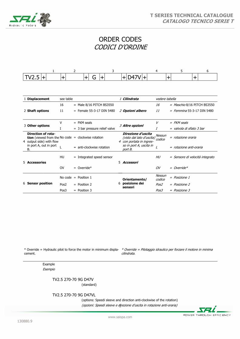
ORDER CODES CODICI D’ORDINE
Example Esempio TV2.5 270-70 9G D47V (standard) (options: Speedi sleeve and direction anti-clockwise of the rotation) (opzioni: Speedi sleeve e direzione d’uscita in rotazione anti-oraria)
TV2.5 270-70 9G D47VL
1 Displacement see table 1 Cilindrata vedere tabella
2 Shaft options
16 = Male 8/16 PITCH BS3550
2 Opzioni albero
16 = Maschio 8/16 PITCH BS3550
11 = Female 55-3-17 DIN 5480 11 = Femmina 55-3-17 DIN 5480
3 Other options V = FKM seals
3 Altre opzioni V = FKM seals
I = 3 bar pressure relief valve I = valvola di sfiato 3 bar
4
Direction of rota-tion (viewed from the output side) with flow in port A, out in port B.
No code = clockwise rotation 4
Direzione d'uscita (visto dal lato d'uscita) con portata in ingres-so in port A, uscita in port B.
Nessun codice = rotazione oraria
L = anti-clockwise rotation L = rotazione anti-oraria
5 Accessories
HU = Integrated speed sensor
5 Accessori HU = Sensore di velocità integrato
OV = Override* OV = Override*
6 Sensor position
No code = Position 1
6 Orientamento/
posizione dei sensori
Nessun codice = Posizione 1
Pos2 = Position 2 Pos2 = Posizione 2
Pos3 = Position 3 Pos3 = Posizione 3
1 2 3 4 5 6
TV2.5 + + + G + + D47V + + +
* Override = Hydraulic pilot to force the motor in minimum displa-cement.
* Override = Pilotaggio idraulico per forzare il motore in minima cilindrata.

1
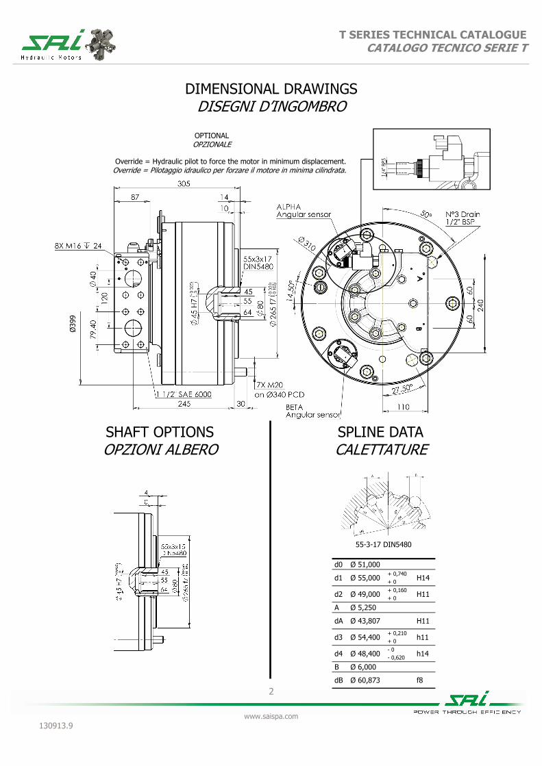
www.saispa.com 130913.9
T SERIES TECHNICAL CATALOGUE CATALOGO TECNICO SERIE T
TV3.5
450 110 600 150 800 200 1000 250 1100 280 1200 300
Equivalent displacement [cc/rev] 445 111 596 149 832 208 965 241 1108 277 1222 305
Cilindrata equivalente Bore
[mm] 38 44 52 56 60 63 Alesaggio Stroke
[mm] 56 14 56 14 56 14 56 14 56 14 56 14 Corsa Specific torque
[Nm/bar] 7,08 1,77 9,48 2,37 13,24 3,31 15,36 3,83 17,63 4,41 19,45 4,85 Coppia specifica Continuous pressure
[bar] 400 400 400 400 400 400 400 400 400 400 350 350 Pressione in continuo Peak pressure ⁽1⁾
[bar] 450 450 450 450 450 450 450 450 450 450 400 400 Pressione di picco ⁽1⁾ Peak power
[kW] 220 180 220 180 220 180 220 180 220 180 220 180 Potenza di picco Continuous speed
[rpm] 700 1400 700 1400 550 1400 550 1400 500 1300 500 1300 Velocità in continuo Maximum speed
[rpm] 900 1800 800 1800 700 1800 700 1800 650 1600 650 1600 Velocità massima Approximative weight
[kg] 120 unit Motor oil capacity
[l] 4 Peso approssimativo unità Capacità olio motore
Maximum casing pressure (2) [bar]
5 continuous
Admissible temperatures [°C]
-20 minimum
continuo minimo Pressione massima in carcassa (2)
15 peak
Temperature ammissibili +80 maximum
picco massimo
Override change displacement pilot pressure range
[bar] 15 - 40
Override change displacement pilot oil capacity
[cm3] 1,5
Campo di pressione di cambio cilindrata override
Capacità olio di cambio cilindrata override
Bolt torque setting [Nm] 561-697
coarse 586-736
fine Suggested bolt type M20 12.9
Coppia serraggio viti grosso fine Viti suggerite NOTES
(1) Continuous or average working pressure should be chosen depending on the bearing lifetime. For lifetime calculation of the motor bearings, please contact the SAI Technical
(1) La pressione continua o media di lavoro va determinata in funzione della vita dei cuscinetti. Per un calcolo di vita dei cuscinetti del motore contattare l’Ufficio Tecnico SAI.
(2) For higher casing pressure please contact the SAI Technical Department.
(2) Per pressioni più elevate in carcassa contattare l’Ufficio Tecnico SAI.
Zero displacement available on request
Cilindrata zero disponibile su richiesta
2
www.saispa.com 130913.9
T SERIES TECHNICAL CATALOGUE CATALOGO TECNICO SERIE T
DIMENSIONAL DRAWINGS DISEGNI D’INGOMBRO
Override = Hydraulic pilot to force the motor in minimum displacement. Override = Pilotaggio idraulico per forzare il motore in minima cilindrata.
OPTIONAL OPZIONALE
SHAFT OPTIONS OPZIONI ALBERO
SPLINE DATA CALETTATURE
55-3-17 DIN5480
d0 Ø 51,000
d1 Ø 55,000 + 0,740
H14 + 0
d2 Ø 49,000 + 0,160
H11 + 0
A Ø 5,250
dA Ø 43,807
H11
d3 Ø 54,400 + 0,210
h11 + 0
d4 Ø 48,400 - 0
h14 - 0,620
B Ø 6,000
dB Ø 60,873 f8
Ø39
9

T SERIES CATALOGUE CATALOGO TECNICO SERIE T
3
www.saispa.com 130913.9
GRAPHS GRAFICI
UNIT DISPLACEMENT - CILINDRATA UNITÀ L10 LIFETIME - VITA L10
PRES
SURE
- PR
ESSI
ON
E (b
ar)
PISTON DIAMETER - DIAMETRO PISTONE (Ø mm)
HO
UR
S -
ORE
UNIT SPEED - VELOCITÀ DELL’UNITÀ (rpm)
100 bar
28 33 38 43 48
0 200 400 600 800 1000 1200 1400
130
28
340
44
100
200
500
1.000
2.000
5.000 10.000 20.000 50.000
100.000 200.000 500.000
1.000.000
210
35
240
37
400
48
Bearing lifetime has been estimated according to L10 (according to ISO 281:1990). The following graph has been plotted using the maximum displa-cements with the stroke of 32 mm. Please contact the SAI Tech-nical Department for other graphs relating to this product.
La durata è stata calcolata in accordo con la formula L10 (secondo ISO 281:1990). Il grafico che segue è stato ricavato usando le cilindrate massime e la corsa di 32 mm. Vi preghiamo di contattare l’Ufficio Tecnico SAI per altri grafici relativi a questo prodotto.
UNIT DISPLACEMENT - CILINDRATA UNITÀ L10 LIFETIME - VITA L10
PRES
SURE
- PR
ESSI
ON
E (b
ar)
PISTON DIAMETER - DIAMETRO PISTONE (Ø mm)
HO
UR
S -
ORE
UNIT SPEED - VELOCITÀ DELL’UNITÀ (rpm)
28 33 38 43 48
0 200 400 600 800 1000 1200 1400 1600 1800 2000 2200 2400 2600
100
200
500 1.000 2.000 5.000
10.000 20.000 50.000
100.000 200.000 500.000
1.000.000
Bearing lifetime has been estimated according to L10 (according to ISO 281:1990). The following graph has been plotted using the minimum displa-cements with the stroke of 8 mm. Please contact the SAI Techni-cal Department for other graphs relating to this product.
La durata è stata calcolata in accordo con la formula L10 (secondo ISO 281:1990). Il grafico che segue è stato ricavato usando le cilindrate minime e la corsa di 8 mm. Vi preghiamo di contattare l’Ufficio Tecnico SAI per altri grafici relativi a questo prodotto.
100 bar
30
28
90
44
50
35
60
37
100
48

4
www.saispa.com 130913.9
T SERIES TECHNICAL CATALOGUE CATALOGO TECNICO SERIE T
ORDER CODES CODICI D’ORDINE
Example Esempio TV3.5 800-200 9G D907V (standard) (options: FKM seal and direction anti-clockwise of the rotation) (opzioni: tenute in FKM e direzione d’uscita in rotazione anti-oraria)
TV3.5 800-200 9GV D907VL
1 Displacement see table 1 Cilindrata vedere tabella
2 Other options V = FKM seals
2 Altre opzioni V = FKM seals
I = 3 bar pressure relief valve I = valvola di sfiato 3 bar
3
Direction of rota-tion (viewed from the output side) with flow in port A, out in port B.
No code = clockwise rotation 3
Direzione d'uscita (visto dal lato d'uscita) con portata in ingres-so in port A, uscita in port B.
Nessun codice = rotazione oraria
L = anti-clockwise rotation L = rotazione anti-oraria
4 Accessories 4 Accessori OV = Override* OV = Override*
5 Sensor position No code = Position 1
5 Orientamento/
posizione dei sensori
Nessun = Posizione 1
Pos2 = Position 2 Pos2 = Posizione 2
Pos3 = Position 3 Pos3 = Posizione 3
1 2 3 4 5
TV3.5 + + 9 + G + + D907V + + +
* Override = Hydraulic pilot to force the motor in minimum displa-cement.
* Override = Pilotaggio idraulico per forzare il motore in minima cilindrata.

SAI Hydraulics Inc. 168 East Ridge Road, Suite 106
Linwood, PA 19061(610) 497-0190 FAX (610) 497-0197
SAI Hydraulics Canada LTD.6105 Boulevard Couture
St. Leonard, PQ H1P 3G7(514) 323-4552 FAX (514) 323-8780
www.saihyd.com