tests of steel moment connections lynn s. …digital.lib.lehigh.edu/fritz/pdf/205_79.pdf · fritz...
TRANSCRIPT
TESTS OF STEEL MOMENT CONNECTIONS
Lynn S. Beedle
and
Richard Christopher
October 4, 1963
Fritz Engineering LaboratoryDepartment of Civil Engineering
Lehigh UniversityBethlehem, Pennsylvania
Fritz Engineering Laboratory Report No. 205.79

205.79
TESTS OF STEEL MOMENT CONNECTIONS
by
Lynn S. Beedlel
and Richard Christopher2
$¥NOPSIS
This report has been written to consolidate and discuss the results
of some of the more important studies of rigid moment connections in
building frames, and to suggest some possible areas of future work.
-i
Three types of connecting media are considered: welding, riveting,
and bolting. In turn, three types of connections receiv~ primary attention.
These are the corner connection, the beam-to-column connection, and ~he
beam splice. Primary attention is focused upon the moment capacity and. .. . ?The- c\{':te\";~", lA.,>ec\ \... -\-\.';" n~oA ,,> ~le C\.~: hty at \
?e~~rmat~~+: capac~ty ,of these connect~op's.. -t~e cOIA.\II.<?C.hClV\. -tb lA.....Ae..~ c> \",,~\C\.~t:Lc,~l"t>..h ... ¥"e'>lA.~t\~1I"'" ,f l
....t re+"" 10"'\ \'"Cl\<\Y t,~S ~J C\sSOc.:",,+Qcl w~t\. t\.\~f;c..l '1~Qte.\\'')lA>~~\e PV-C\l:C\~IAC~ Q. pv-<?c\k+o..lo\e
resh-t\~ ~.V\ej.The tests reported herein were conducted at the following schools:
Cambr~dge University, Cornell University and Lehigh University. Investigations
of significance conducted at other schools are also briefly considered.
The ~ost important result of these tests is that for all properly
designed and detailed, welded and bolted moment connections, the plasticplClSt,'c::; V-otCl:\ "0"\
moment of the adjoining member was reached and large"eefe-rmaeiea capacities
were observed. There were no premature failures except those which could
have been predicted and prevented.
IResearch Professor of Civil Engineering and Director of Fritz Engineering
2 Laboratory, Lehigh University, Bethlehem, Pennsylvania.Research Assistant, Fritz Engineering Laboratory, Department of CivilEngineering, Lehigh University, Bethlehem, Pennsylvania.
205.79
TABLE OF CONTENTS
Page
SYNOPSI$ i
l. INTRODUCTION 1
2. TyPES Or CONNECTIONS 3
;3. WELDED CONNECTIONS 3
4. RIVETED CONNECTIONS 6
5. BOLTED CONNECTIONS 7
6. DISCUSSION 13
7. SUMMARY 14
8. ACKNOW~EDGMENTS 15
9. FIGURES 17
10. REFERE;NCES 23
ii
205.79
1. INTRODUCTION
With the increasing use of plastic analysis and design, additional
emphasis is being placed on the design of all types of moment resisting
connections. Simple plastic theory assumes that a connection will be
-1
capable of developing the fu~l
wIll be )\-1/'0" IL
members. It also assumes that
plastic moment" of one or more adjoining~ 0 -lltct-t ~(!st" C\aJe\......~ ~ ....Wli ~t;oV\
the connection w~ ~ have a~.:ilatioI1
capacity ·ckat is sufficient to allow the formation of the prescribed
mechanism without premature failure.
This report is primarily a review of test results of steel moment
connections and will include a discussion of welded, riveted and bolted
joints for buildings. Bridge connections will not be considered here because
of the nature of the applied loading which includes impact, repeated loading,
and moving loads.
Principal attention also will be confined to "rigid" moment connections--
those that must develop the full plastic moment of the connecting member as
shown by the upper curve in Fig. 1. In "simple" and "semi-rigid" connections,
also shown in this figure, primary attention focuses on the stiffness of the
connection (the elastic slope of the moment-rotation curves in Fig. 1).
Essentially what is desired in a rigid connection is the ability to develop
t~e plastic moment. The stiffness of a rigid connection is not of primary
interest, since the rigid type always introduces enough material to limit the
"elastic" unit rotation to the same order of magnitude as that of the member
bein& connected. Assuming that the columns provide complete fixity, the

205.79 -2
occurs after M is reached at thep
that subsequently the plastic moment
resulting rigidity gives an elastic distribution of moment (shown with the
2 2dashed line at the right in sketch a) of wL /12 at the ends and wL /24 at
the center. The inelastic rotation that\."o~ *hQ. \9QQ.lM J
enasApermits redistribution of moment so
is reached at the center. Under the action of gravity plus wind loading,
shown in diagram (b) of Fig. 1, the"hinge action" permits full participation
of the beam and the connections in resisting lateral load.
The welded connection is a familiar moment resisting joint, and has been
used extensively. Figure 2 shows a welded beam-to-beam column connection of
the "top-plate" type. There have been many investigations of welded connections
(primarily under the auspices of the Welding Research Council), and a number of
the more important studies will be discussed.
The riveted connection is by far the oldest of the three types. However,
only brlef attention will be given to this type for two reasons:
1. Most tests of riveted moment connections were performed many
years ago and were not carried sufficiently past working loads
to indicate their behavior near the plastic moment.
2. Bolts are replacing rivets in the design of many moment connections.
The bolted connection has been steadily growing in prominence since the
first specification for high strength bolts was introduced in 1949. The use
of high strength bolts represents a significant contribution, and was made
possible through extensive structural research under the guidance of the
Research Council on Riveted and Bolted Structural Joints. Figure 3 shows a
bolted interior beam-to-column connection;.
205.79
2. TYPES OF CONNECTIONS
-3
There are'many types of steel moment connections, only a few of which
can be discussed in this paper. Figure 4 shows different classifications.
of rigid connections in building frames. They include:
(1) Splices, which could be sp'1ices :in beams, at the peak of a
roof, or in columns.
(2) Corner Connections, which may be of the straight or of the
haunched type.
(3) Miscellaneous Connections, which cover attachments of purlins
and girts to the main frame.
(4) Beam-to-Girder Connections, which include the attachment of beams
to girders at right angles to the plane of the frame,
(5) Beam-to-Column Connections, which could be of the "side", "top",
or "interior" type as indicated in the figure.
(6) Column Bases.
Principal attention in this paper will be given to beam-to-column
connections, to splices (especially beam splices), and to corner connections.
3. WELDEDED CONNECTIONS
In examining the behavior of welded joints, straight corner connections
(those withoup a haunch) are of initial interest. In Fig. 5, load is plotted
against deflection for a rigid straight corner connection fabricated from
30WF108 shapes. It was tested as part of a Lehigh University study. The(1)
dotted line shows the theoretical behavior, and the solid line through

205.79 -4
the points shows the results of the test and demonstrates the ability of such
co~nections to develop·the plastic moment, M , and to rotate through ap .
considerable angle. This curve is characteristic of welded corner connections
des~gned to develop M :p
(1) . The initial portion of the curve closely follows the predicted
elastic slope.
(2) Strain-hardening produces some increase in strength above the
load corresponding to M .P
(3) After considerable deformation the curve "unloads" due to local
and lateral buckling, and eventually falls below Mp
(4) In this case the deformation capacity was about 8 times the
"elastic limit" deformation (the deformation at which the member
theoretically first reaches M ).P
Connections such as the one shown in Fig. 5 are most easily proportioned(2)
using elementary plastic analysis. For example, as shown in Fig. 6, if
the top flange is isolated it is seen that the reaction to the force T is
made up of the resistance of the web, T , and that of the stiffener, Tw s
Now, the maximum possible values of these resisting forces exist when both
the web and the st~ffener are completely yielded. Therefore, the area of
stiffener required to resist the plastic moment can be obtained simply by
solving the equilibrium between the force T and the sum, Tw plus Ts ' or
205.79 -5
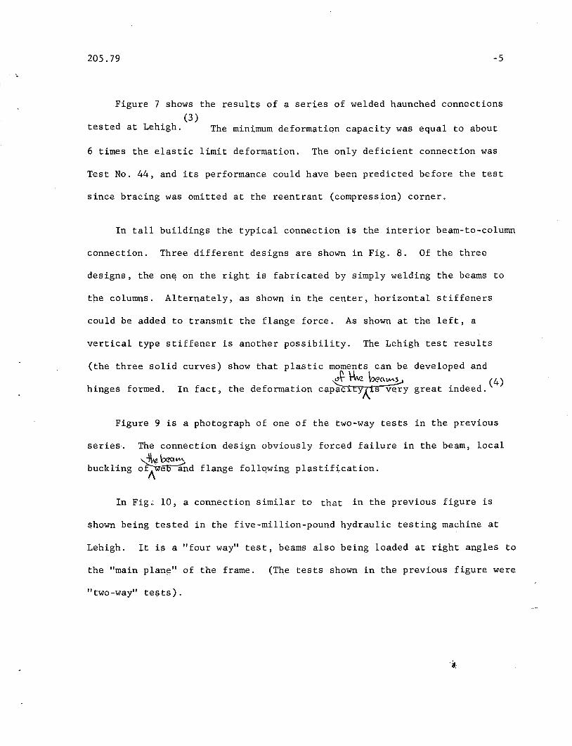
Figure 7 shows the results of a series of welded haunched connections(3 )
tested at Lehigh. The minimum deformation capacity was equal to about
6 times the elastic limit deformation. The only deficient connection was
Test No. 44, and its performance could have been predicted before the test
since bracing was omitted at the reentrant (compression) corner.
In tall buildings the typical connection is the interior beam-to-column
connection. Three different designs are shown in Fig. 8. Of the three
designs, the on~ on the right is fabricated by simply welding the beams to
tne columns. Alternately, as shown in the center, horizontal stiffeners
could be added to transmit the flange force. As shown at the left, a
vertical type stiffener is another possibility. The Lehigh test results
(the three solid curves) show that plastic moments can beJ \ok bea~
hinges formed. In fact, the deformation capac~tyx:s very
developed and
. (4)great ~ndeed.
Figure 9 is a photograph of one of the two-way tests in the previous
series.
buckling
The connection design obviously forced failure
"..-\l.t beClIM.o~web (nd flange follqwing plastification.
in the beam, local
In Fig;" 10, a connection similar to that in the previous figure is
shown being tested in the five-million-pound hydraulic testing machine at
Lehigh. It is a "four way" test, beams also being loaded at right angles to
the "main plan!='.' of the frame. (The tests shown in the previous figure were
"two-way" tests).
205.79 -6
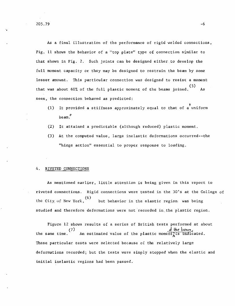
'.As a final illustration of the performance of rigid welded connections,
Fig. 11 shows the behavior of a "top plate" type of connection similar to
that shown in Fig. 2. Such joints can be designed either. to develop the
full moment capacity or they may be designed to restrain the beam by some
lesser amount. This particular connection was designed to resist a moment
(5)that was about 60% of the full plastic moment of the beams joined. As
seen, the connection behaved as predicted:
\1(1) It provided a stiffness approximately equal to that of a uniform
1/,beam.
(2) It attained a predictable (although reduced) plastic moment.
(3) At the computed value, large inelastic deformations occurred--the
"hinge action" essential to proper response to loading.
4. RIVETED CONNECTIONS
As mentioned earlier, little attention is being given in this report to
riveted connections. Rigid connections were tested in the 30's at the College of(6)
the Ci~y'of' New York, but behavior in the elastic region: was being
studied and therefore deformations were not recorded in,the plastic region.
of British tests performed at about
of -",e 6e"....."An estimated value of the plastic mome~t~is in~ated.
Figure 12 shows results of a series(7)
the same time.
These particular tests were selected because of the relatively large
deformations recorded; but the tests were simply stopped when the elastic and
initial inelastic regions had been passed.
205.79
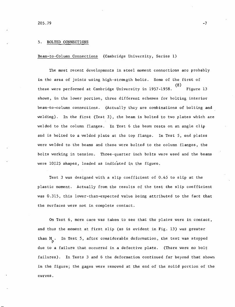
5. BOLTED CONNECTIONS
Beam-to-Column Connections (Cambridge University, Series 1)
-7
The most recent developments in steel moment connections are probably
in the area of joints using high-strength bolts. Some of the first of(8)
these were performed at Cambridge University in 1957-1958. Figure 13
shows, in the lower portion, three different schemes for bolting interior
beam-to-column connections. (Actually they are combinations of bolting and
welding). In the first (Test 3), the beam is bolted to two plates which are
welded to the column flanges. In Test 6 the beam rests on an angle clip
and is bolted to a welded plate at the top flange. In Test 5, end plates
were welded to the beams and these were bolted to the column flanges, the
bolts working in tension. Three-quarter inch bolts were used and the beams
were 10125 shapes, loaded as indicated in the figure.
Test 3 waS designed with a slip coefficient of 0.45 to slip at the
plastic moment. Actually from the results of the test the slip coefficient
was 0.315, this lower-than-expected value being attributed to the fact that
the surfaces were not in complete contact.
On Test 6, more care was taken to see that the plates were in contact,
and thus the moment at first slip (as is evident in Fig. 13) was greater
than M. In Test 5, after considerable deformation, the test was stoppedp
due to a failure that occurred in a defective plate. (There were no bolt
failures). In Tests 3 and 6 the deformation continued far beyond that shown
in the figure; the gages were removed at the end of the solid portion of the
curves.

205.79 -8
In Fig. 14 the data from Test 6 of Fig. 13 is repeated and is compared
with the test results for two welded connections.(9) In general it can be
seen that the qehavior of the bolted connection is basically the same as the
welded ones insofar.as the ability to develop plastic moments is concerned.
One difference is the slight additional stiffness in the "elastic" range for
the bolted joint because of the added plate material in the lap area. The
high clamping force of the bolts develops enough friction so that the whole
assembly tends to act together. In both the bolted and welded joints of
this series the final performance is not limited by the connection material
but instead depends upon the a~ilitY'of the beam to rotate plastically.
Beam-to-Column Connections (Cambridge University, Series 2)
The next series of tests conducted at eambridge University, England, was
confined to the type that offers the greatest simplicity and economy from
(10)the standpoint that it requires the fewest number of bolts. The three
speci,meps in "Group A" are shCMn in the lower part of Fig. 15. In such
connections the bolts transmit some shear, but are primarily loaded in
tension. The specimens were loaded as in the previous series (Fig. 13),
with a concentrated load applied to the column stub; the reactions were
carried at the beam ends.
The first group used 3/4 inch bolts, recognized at the outset as being
undersized. The basis for the design was that all bolts would be at "yield"
(selected as the proof load) when the beam reached M. Thus, a redistributionp
of force~ in the bolts was assumed.
205.79
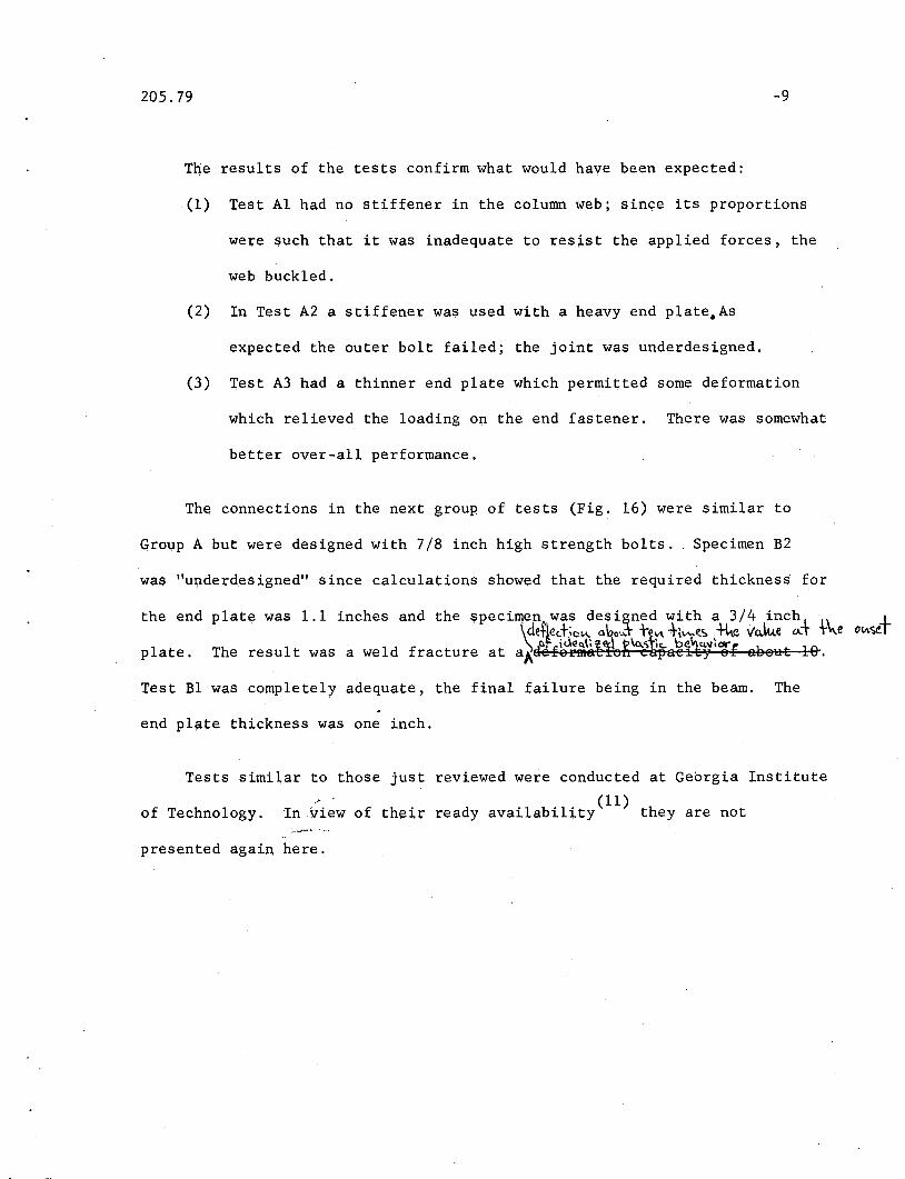
The results of the tests confirm what would have been expected:
-9
(1) Test Al had no stiffener in the column web; since its proportions
were such that it was inadequate to resist the applied forces, the
web buckled.
(2) In Test A2 a stiffener was used with a heavy end plate.As
expected the outer bolt failed; the joint was u~derdesigned.
(3) Test A3 had a thinner end plate which permitted some deformation
which relieved the loading on the end fastener. There was somewhat
better over-all performance.
The connections in the next group of ~ests (Fig. 16) were similar to
Group A but were designed with 7/8 inch high strength bolts. Specimen B2
was "underdesigned" since calculations showed that the required thickness for
the end
plate.
plate was 1.1 inches and the speci~ep was designed with a 3/4 inchJI\\deth+';c~ a\:,Cu.+ t~\t\ +l.......(.C;, ~ vC\.\u.e ,,-, l~e,\ of icle~\' <1d \o..<,tk. be cw~'*'The result was a weld fracture at aAdef8Fffl~~og eapae~~y sf eeSHE 1&.
Test Bl was completely adequate, the final failure being in the beam. The
end pl~te thickne$s was one inch.
Tests similar to those just reviewed were conducted at Georgia Institute
of Technology, In view of their ready availability(ll) they are not
presented again here.
205.79 -10
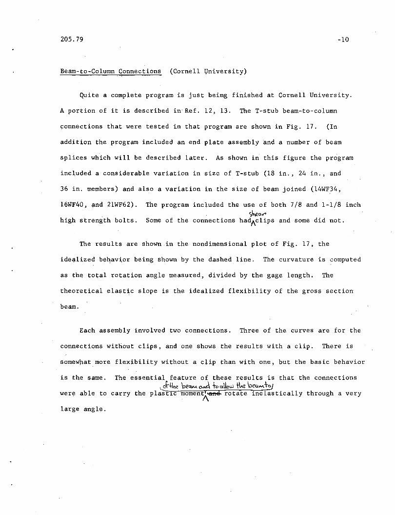
Beam-to-Column Connections (Cornell University)
Quite a complete program is just being finished at Cornell University.
A portion of it is described in Ref. 12, 13. The T-stub beam-to-column
connections that were tested in that program are shown in Fig. 17. (In
addition the program included an end plate assembly and a number of beam
splices which will be described later. As shown in this figure the program
included a considerable variation in size of T-stub (18 in., 24 in., and
36 in. members) and also a variation in the size of beam joined (14WF34,
16WF40, ~nd 21WF62). The program included the use of both 7/8 and 1-1/8 inchS~aV"
high strength bolts. Some of the connections hadAclips and some did not.
The results are shown in the nondimensional plot of Fig. 17, the
idealized beqavior being shown by the dashed line. The curvature is computed
as the total rotation angle measured, divided by the gage length. The
theoretical elastic slope is the idealized flexibility of the gross section
beam.
Each assembly involved two connections. Three of the curves are for the
connections without clips, and one shows the results with a clip. There is
somew~at more flexibility without a clip ~han with one, but the basic behavior
is the same. The essential feature of these results is that the connections~*",e \:>eCUM~ toatle"" tk \neulM+~
were able to carry the plast~c moment)\~ rotate inelasticalLy through a very
large angle.
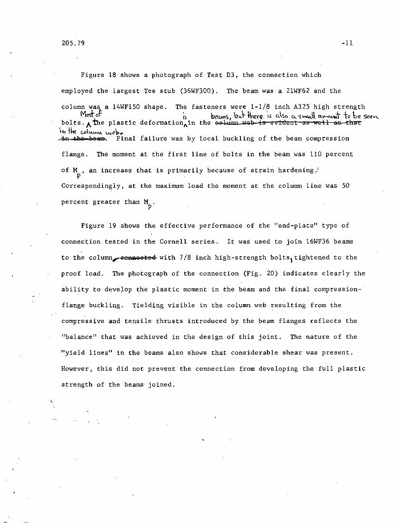
205.79 -11
Figure 18 shows a photograph of Test D3, the connection which
employed the largest Tee stub (36WF300). The beam was a 2lWF62 and the
failure was by local buckling of the beam compression
l4WF150 shape. The fasteners were 1-1/8 inch A325 high strengthI~ be<t\lt\S} bJ -\kV'G"\S 0..\':.0 c... ')~ o..\ho~t to b~ <3eC!",-
deformation"in the Gelump xl1e's is evident as well as that
column was aMoSfo-t
bolts. A the plastic'11'\ the (..0\1.1.""'\1\ w(1\t>...4R &ae beam. Final
flange. The moment at the first line of bolts in the beam was 110 percent
of N , an increas~ that is primarily because of strain hardening~!p
Correspondingly, at the maximum load the moment at the column line was 50
percent greater thanM .p
Figure 19 shows the effective performance of the lIend-plate ll type of
connection tested in the Cornell serie$. It was used to join l6WF36 beams
to the column,..lffiPlaeSl:ee with 7/8 inch high-strength bolts) tightened to the
proof load. The photograph of the connection (Fig. 20) indicates clearly the
ability to develop the plastic moment in the beam and the final compression-
flange buckling. Yielding visible in the column web resulting from the
compressive and tensile thrusts introduced by the beam flanges reflects the
IIbalance ll that was achieved in the design of this joint. The nature of the
lI yield lines ll in the beams also shows that considerable shear was present.
However, this did not prevent the connection from developing the full plastic
strength of the beams joined .
.'.

205.79 -12
Beam Splices (Cambridge Series)
The final group of connections which will be examined briefly are
bolted splices in beams. Figure 21 shows the test setup used at Cambridge
in 1958 and the two splices whicQ were tested. (8) The first was designed
as a riveted full-moment splice,bolts being sub$tituted for rivets on a
one-to-one basis. Test 2 (quite arbitrarily) was designed using just half
as many bolts, The results are shown on a moment versus deflection basis,
with the theoretical deflection of the uniform beam as indicated. ~Als.o the
plastic mom~nt of the beam and the reduced plastic moment allowing for bolt
holes, M are shown.pr'
Test No. 1 exceeded both the reduced plastic moment andM , no slipp
being observeq in the test. After the gages were removed deformation was
continued until the beams buckled. The stiffening effect of the splice
plates, noted in the conn~ction with earlier tests, is evident. In test No.2
slip occurred at a moment value between M and M , the slip coefficient forpr p
these particular tests being 0.49. Of special interest is the fact that
strength in excess of Mp is developed by these joints even though, theoretically,
25% of the plastic strength is removed by the bolt holes. This is the result
of the recognized effects of strain-hardening and stress-concentrations.
Beam Splices (Cornell Series)
Three identical beam splices with lap connections were tested in the
Cornell University program previously described! l6WF36 beams were used, the
7/8 inch bolts being loaded in shear. Figure 22 shows the results on a

205.79
nondimensional basis, and in comparison with the plastic moment of the
-13
gross section. and of the net sectiqn of the beam. The heavy dashed curve
gives the results from the test of a plain unspliced beam. The bolts were
design~d on the basis of 22 ksi as permitted in bearing type connections.
None 9f the connections slipped below the working load P (shown asw
0.6 P ), and all of the connections developed the full plastic moment ofy
the gross cross section and showed satisfactory deformation characteristics.
The photograph in Fig. 23 shows that the splices obviously were able to
develop the full ~lastic moment, forcing local buckling to take place in the
beam compression flange.
The final tests in the Cornell series to be mentioned in this repor~
are shown in Fig. 24, consisting of a beam splice using plates welded to the
beams and loaded in pure moment. Test C5, with eight 3/4 inch A325 bolts
performed better than C2 with six 7/8 inch b91ts, indicating again the
advantage of extend~ng the plate beyond the tension flange of the beam.el ctw:\C~.
Figure 25 is a photograph of 8S@R beams~ Test C5 is shown at the bottom of
the photograph .'""Ths+ (.\ '\'l ") \'M.' \0.... ~""- af~nV'CI.""c.e -\0 C2 ..
6. DISCUSSION
Figure 26 summarizes the present situation with respect to rigid moment
connections. There if? practically no information available on the ability of
riveted ~onnections to develop the plastic moment. This is not because of any
fumiamental difficulties, but is simply because no tests have been conducted.
With respect to welded connections, the major problems appear to be solved,
although special items will require attention.
205.79 -14
Many of the basic problems involved ~n bolted connections are solved,1-+ \S t)~ i"'~'-Cl.J t~t
but some further research is needed. A ~= .wapt§.... no tEAsts have yet come. \\,1$ C1~e\Ub\J.e~ bolkJ +0~ ic.uw.\cJ:c'-'\. I
to light on bp]~8S column baset~ Among other areas of needed research are:
1. Beam-to-dolumn connections with unequal beam moments.L~ ....i~; "'V 6( c
2.~~on01tions under which bolt holes may be neglected when
computing M .P
3. Response of joints to reversed loading of the type which would
be encountered in strong earthquakes.
Nevert4eless, information available to date makes it abundantly clear that
if a rotation capacity (or ductility factor) of 8 to 10 is not realized~a~
a steel moment connection, it is because some detail has been underdesigned.
7. SUMMARY
This review of tests on rigid steel moment connections of the type used
iq building construction may be summarized as follows:
1. For ~ll properly designed and detailed welded and bolted moment
connections, the plastic moment of the adjoining member was
reached and large deformation capacities were observed. There
were no premature failures except those which could have been
predicted and prevented.
2. Welded connections can be designed for a reduced moment withoutQ.bs\-:e- ~\o,'itic..
sacrificing~rigidity orAdeformation capacity ~g. 11).
3. Very little information is available conc~rning riveted moment
connections. Most early work did not give attention to the plastic
region.

205.79 -l?
4. The behavior of bolted connections is essentially the same as that
of welded connections with respect to moment and deformation
capacities. The lap type bolted connection has a somewhat greater
initial stiffness due to the added effective plate area... ~Qiiylt:iftg.
i£Qm ~be Riga elam~i~g f~~1
5. In lap type bolted connections, the actual buckling failure is
forced to occur outside the connection in . the member itself, even
though a higher moment may be present within the connection.
6, The r~duced -.e area caused by the bolt holes in lap type connections
had no adverse effect for any of the tests examined.
7. There are a number of areas where research is needed, some of which
have been noted in the discussion. One of the most important of
these is the response of steel moment connections to reversed
loading of a limited number of ~ycles.
8 . ACKNOWLEDGMENTS
This report has been written as a review of some of the more important
tests of moment connections. The authors are indebted to those at other
in~titutions who made their information available. Among these are
A. N. Sherbourne, Ph.D., M. A., A. M. I. Struct. E, (of the University of
Waterloo), and L, G. Johnson, M. A., A. M. 1. Struct. E. (of Dorman-~lD~
and Company) for the work done at Cambridge University, and also W. McGuire,
Profe$sor, Cornell University and R. Douty, Assistant Professor, University
of ~issouriwith respect to their work at Cornell Unive~sity.

205.79 -16
Acknowl~dgment is also due the Lincoln Electric Company and the
Bethlehem Steel Company for the photo~raphs they so generously furnished.
This report has been written as a part of an investigation of welded
continuous frames and their components, being conducted at the Fritz
Engineering Laboratory, Department of Civil Engineering, Lehigh University.
Professor William J. Eney is the head of the department and laboratory.
Appreciation is due the members of the Lehigh Project Subcommittee of the
Welding Research Couq.cil for their suggestions and encouragement.
The drawings and photographs were prepared by Messrs. R. Sopko,
J. Szilagyi and H. A. Izquierdo, and the manuscript was tYPed by
Miss Marilyn Courtright.

20).79 -17
9. FIGURES

205.79
M
e
r----'I SEMI'I RIGID:L -J
H""""'"""!!!""""IW""""""!!!R
~~(a)..4lI1 (b)
~
-18
Fig. 1 TYPES OF CONNECTIONS Fig. 2 WELDED MOMENT CONNECTION
® @®
® CD ®- l--------@ @ @---I
® ®-
BEAM- GIRDER
BEAM-COLUMN I
COLUMN BASE
Fig. 3 BOLTED BEAM-TO-COLUMN CONNECTION Fig. 4 TYPES OF RIGID CONNECTIONS IN BUILDING FRAMES

-19
A2
40
A2
86
181
CII
DEFLECTION, inches1.0
-- - - -- - - £I~ - - - - - - - __ Mp
FORCEDISTRIBUTION
'" TOP FLANGE~~:: ,~, I \ EQUILIBRIUM
T A .,. u. u.Z~=~. Iwiiwd T=~
Fig. 6 PLASTIC ANALYSIS OF A CORNER CONNECTION
60
o
Fig. 8 BEHAVIOR OF WELDED BEAM-TO-COLUMN CONNECTIONS
PkipS
Fig. 10 TESTING A FOUR-WAY CONNECTION
100
30W"108
50
~10o
DEFLECTION IN INCHES
00~----'--:---o----';------:---6:---=----':-..J
05
150
1.0
Fig. 5 WELDED CORNER CONNECTION
Fig. 7 BEHAVIOR OF HAUNCHED CORNER CONNECTIONS
Fig. 9 BEAM-TO-COLUMN CONNECTION AFTER TESTING
LOAD"p"
(kips)
205.79

205.79 "-20
20
120
-- - -- - - --- - - Mp ----- -------- Mp
100 100
120
) 141<1'""30
r------------------------------Mp////
J/
f -;:--=--~-~-"'=""=-=--::-:"':-:--=-=--:-:-::-=--:-::--:-=-=- - - Mpr/
120
160
Mkip·tt.
o 5 10 15 0
8. Radians
10 15,,0.3
Fig. 11 WELDED CONNECTION DESIGNED FOR A REDUCED MOMENT Fig. 12 EARLY TESTS OF RIVETED CONNECTIONS
~IOI25®
La
@l
~~::::=",.....--::~:~--:@
DEFLECTION,in. 08
® @l0.2
400
Gao
MTon.i
1.21.0®
DEFLECTION, inches
~'OI25
qpqp~02
MTon in.
600
Fig. 13 BEHAVIOR OF BOLTED BEAM-TO-COLUMN CONNECTIONS Fig. 14 COMPARISON OF BOLTED AND WELDED BEAM-TO-COLUIIN CONNECTIONS
A3
200 200BI
B2
----- Mp
150
Mkip-It.
50
(t{)Jl $ ttJ (tW) tWAI A2 A3 81 82
15142 Beams 3/4'Bolts 15142 Beams "Va'Bolts
a 1.0DEFLECTION, inches
40 a 1.0 DEFLECTION, inches 4.0
Fig. 15 BEHAVIOR OF END PLATE CONNECTIONS Fig. 16 BEHAVIOR OF END PLATE CONNECTIONS

205.79 -21
15.0
-- D3
10.0'.0
./ D2
~ DI Clip .'_ DI
-------r--~- Mp
I L 8
i AA'O\,---------., ~
18 \IF 70 lJI 141'F3424 1 105.9 02 16 I'F 4036 I'F 300 03 211'F 62
o 10
Fig. 17 BOLTED T-STUB CONNECTIONS Fig. 18 T-STUB CONNECTION AFTER TESTING
-----------------~
3.0
p p
~1.0
60
80
Fig. 19 END PLATE TYPE OF BEAM-TO-COLUMN CONNECTION Fig. 20 END PLATE CONNECTION AFTER TESTING
600
10.0
- ----==--=--- __ Mp
GrOSS...... r-_
Plain Beam~------------------Mp Net
1.0
I
%yI
fpwIIIIII
0 1.01.21.0
~-~---®
I d:=eh 10125
DEFLECTION, inch..0.2
'l _
II
II
I '-Uniform BeamI
II
I
200
400
MTon in.
Fig. 21 BEHAVIOR OF BOLTED LAP SPLICES IN BEAMS Fig. 22 BEHAVIOR OF BOLTED LAP SPLICES IN BEAMS

205.79 -22
11 J~ 161'F36
10.0
C5 W~"
1.0
1.0
Fig. 23 FAILURE OF BOLTED LAP SPLICE Fig. 24 BEAM SPLICES - END PLATE TYPE
~DESIGN It;:tTYPE TESTS ANALYSIS GUIDES
Riveted Splice. Corner,Bm;-CoI. 0 0 0 \? I{ Straight X X X \ /
Corner Hounched X X X \/Nelded Brocket X X X 1\
Beom-Cotumn X X X / \Splice X X X I \Corner 0 0 0 Ves
~ItedBeom- Column X X X YesSplice X X X YesColumn Bose 0 X X Yes
X Yes VApplicable Resu"" o No
Fig. 25 COMPARISON OF END PLATE DESIGNS Fig. 26 PRESENT STATUS OF RIGID CONNECTION RESEARCH
205.79
lq. REFERENCES
1. Driscol~, G. C!, Jr. and Beedle, L. S.THE PLASTIC BEHAVIOR OF STRUCTURAL MEMBERS AND FRAMES,Welding Journal, 36 (6), p. 275-s, 1957
2. Beedle, L. S.pLASTIC DES~GN OF STEEL FRAMES,p. 153, John Wiley and Sons, Inc., New York, 1958·
.. 23
3. Fisher, J.W., Lee,.G. C., Yura, J. A. anQ Driscoll, G. C., Jr.,PLASTIC ANALYSIS AND TESTS OF HAUNCHED CORNER CONNECTIONS,Welding Research Council Bulletin No. 91, October 1963
;4.
5.
6.
7.
8.
~O.
11.
Beedle, L. S.EXPERIMENTAL VERIFIC~TION OF PLASTIC THEORY,Proceedings, AISC National Engineering Conference, p. 36, 1956
Pray, R. F. and Jensen, C. D.WELDED TOP PLATE BEAM-COLUMN CONNECTIONS,Welding Journal, 35 (7), p. 338 ..s, 1956
Rathbun, J. C.ELASTIC PROPERTIES OF RIVETED CONNECTIONS,Tran~actions, ASCE, No. 101, Paper No. 1933, p. 524, 1936
Batho, C. and ~owan, H. C.INVESTIGATIONS: ON BEAM AND STANCHION CONNECTIONS,Second Report of the Steel Structures Research Committee,H. M. Stationery Office, London, 1934
Johnson, L. G" Cannon, J. C. and Spooner, L. A.HIGH TENSILE PRELOADED MJ:..r~ESTii n:r J8Ill'i'S BESI8NED 'fO BocrE..e> ~Olt,~n)tllWEI,QP TilE FlJI,L PIJ.STIC MeMEN';FS OF THE COMNEC'fE)) MEMImR&B-dHsh Welding ReSearch Ass()ctatioIl, Confidential ~:epoft
D~/~/5S, ~ltc1~ 1959 'j>.S(:P]B...J\."k Wd ~~ ~o\"\"'Ii\A\>"r;'e\'t~""'ber \'\E>c
"Johnson,. L, G.TESTS ON WELDED CONNECTIONS BETWEEN I-SECTION BEAMS ANDSTANCHIONS,British Welding "Journal, p. 38, January 1959
Sherbourne, A. N.BOLTED BEAM TO COLUMN CONNEXIONS,The Structural Engineer, p, 20q, June 1961
Schutz, F. W., Jr,STRENGTH OF MOMENT CONNECTIONS USING HIGH TENSILE STREN~TH
BOLTS,Proc~edings, AISC National Engipeer~ng COQference, p. 98, 1959

. t
205.19 -24
12. Douty, R. T. and McGuire W.HIGH STRENGTH BOLTED CONNECTIONS WITH APPLICATIONS TOPLASTIC DESIGN~
Third Progre~s Report; Cornell University School ofCivil Engineering, April 1963
13. poUty, R. T. and McGuire, W.RESEARCH ON BOLTED MOMENT CONNECTIONS,Proceedings, AISC National Engineering Conference, 1963