method of computing geometric relations in structural...
TRANSCRIPT

Solid Mechanics, Plasticity, and Limit Analysis
by
. Wai F. Chen
LiBRARY
METHOD OF COMPUTING
GEOMETRIC RELATIONS
IN STRUCTURAL ANALY IS
Fritz Engineering Laboratory Report No. 356..3
Solid Mechanics, Plasticity, and Limit Analysis
METHOD OF COMPUTING GEOMETRIC RELATIONSIN STRUCTURAL ANALYSIS
by
Wai F. Chen
National Sicence FoundationGrant GK3245 To Lehigh University
Fritz Engineering LaboratoryDepartment of Civil Engineering
Lehigh University ,Bethlehem, Pennsylvania
June 1968
Fritz Engineering Laboratory Report No. 356.3

METHOD OF COMPUTING GEOMETRIC RELATIONS INSTRUCTURAL ANALYSIS
Key words: Geometric Relations; Virtual Work Principle; Structural Analysis
*Wai F. Chen
ABSTRACT
A rapid method of computing geometric relations in structural
analysis is presented. It is shorter than the usual methods in many
cases, and can often get the result in one step. It uses vertical and
horizontal dimensions of a structure directly .
..L.
....Assistant Professor, Fritz Engineering Laboratory, Departmentof Civil Engineering, Lehigh University, Bethlehem, Fa.Associate Member ASeE.

INTRODUCTION
The purpose of this paper is to present a method for com-
puting quickly the geometric relationships for connected structural
members. These relationships are often needed in structural analysis.
For example, when using the slope deflection equations for an elastic
1 · 1,2 · I· h b· h· h d 1ana YS1S ,or 10 app y1ng t e com 1ning mec aU1sm met 0 in p astic
. 3-6analys1s , the angle-rotation relationships of the members in the
structure are usually required. It will be shown that the virtual
work equations can provide a simple method for obtaining the desired
1 · h· 7,8re at10ns 1PS
BASIC CONCEPT
The essential feature of the method can be shown by con-
sidering the following two examples:
Example 1
Consider the gabled frame shown in Fig. 1. It is often neces-
sary to find the geometrical relationships which exist for the chord ro-
tations, 0, of the various members. The deflected shape is shown by the
dashed lines in the figure. From the sketch it is apparent that the
four-bar linkage or mechanism has two degrees of freedom, and hence two
independent chord rotations, 0ab and 0de . All chord angles (that is ~bc
and ~cd) may be expressed in terms of ~ab and 0de ,
0bc
will be computed first. Fig. 2a shows an equilibrium
system of external forces and moments applied to the four-bar linkage
-2-

that results when the structure is reduced to a kinematic mechanism.
The equilibrium system for the linkage is obtained in the following
way. Bar cd is assumed to be an axially loaded bar with vertical com-
ponent equal to r 2 and the horizontal component equal to n (i.e. pro
portional to the slope of the bar cd). It produces vertical reactions
r 2 and horizontal reactions n at the two supports. Moment equilibrium
is then established at the remaining joints of the linkage. They are'
equal to nhl , (nr I + mr2) and nh2 at joints a, b, and e respectively.
If the equilibrium system shown in Fig. 2a undergoes the dis-
placements shown in Fig. 1, the virtual work equations gives
The rotation of bar be can be expressed as
(1)
~bc =n
(h2 ~de - hI 0ab )mr2 + nrl(2)
Similarly,har be can be assumed to act as an axially loaded
member. Fig. 2b summarizes the resulting 'equilibrium system and the
virtual work equation yields
The rotation of bar cd can then be expressed as
~cd
-3-
(3)
(4)

The resulting chord rotations agree with the values obtained by Kinney
using the usual geometrical relationship2
Example 2
Consider next the shed-type gable frame with four hinges as
shown in Fig. 3. This mechanism often occurs in plastic analysis. Two
different sets of equilibrium systems are given in Figs. 4a and 4b.
Member be (shaded triangle) and member cd are selected as the axially
loaded members, respectively. The virtual work equations furnishes
for bar be
for bar cd
-Hence, rotations al
and 82
can be expressed as functions of e as
3e = - e1 2
(5)
1e =- e2 2
The total hinge rotation at b is equal to 38/2, the sum of e and 62 ,
-4-

ILLUSTRATIVE ·PROBLEMS
Example 3
Application to the Slope-Deflection Method.
A typical skew frame 'is shown in Fig. 5a. The chord ro
tations shown'in Fig. 5b are usually evaluated using the instantaneous
center concept or the geometrical relations that result from the joint
displacements.' These rotations can easily be evaluated from the pre
sent method. Figure 5c and 5d illustrate its application.
The second factor is the derivation of the "Shear Equatiorr'
to provide the equilibrium condition that is needed in addition to the
two joint equations of equilibrium. This can also be derived by the
virtual work equation. Fig. Se shows the equilibrium system that re
sults when the usual slope-deflection sign convention is adopted, viz.,
end moments are positive when they act clockwise on the ends 'of the
members. If the equilibrium system shown in Fig It Se is displaced as.
shown in Fig. 5b, the resulting work is
The values of 01 and O2 can be substituted and Equation 7 results.
Mab + 2.3 ~a + 2.1 Mcd + 0.8 Mdc + 2,000 = 0
This provides the needed equation of equilibrium without having to
eliminate the shear and axial forces l .
-5-
( 7)

Example 4
Application to the Mechanism Method of Plastic Analysis,
Consider the pin-supported arch shown in Fig, 68, carrying
a concentrated load P at point c, The collapse mechanism of the arch
is shown by the dashed lines with one plastic hinge at c and a second
hinge forming at an unknown section d, Two equilibrium systems are
shown in Fig. 6b, c. The resulting virtual work for the displacements
given in Fig. 6a are
( 8)
[(q+r) i he - (l-q) i (hd-he)] 8 - [(q+r) ~ hd + (l-r) ~ (hd-he)] 81 = 0
These yield rotations 81
and 62 as
(l+r) h - (l-q) hd8
1c e= (l+q) h - (l-r) hd c
(9)
(1-r) h + (l-q) hd8
2c
=(l+q) (l-r) h ehd - c
The work equation for the collapse mechanism (Fig. 6a) is
substituting 61 and 62 from Eqs. 9 and 10 yields the collapse load
-6-
(10)

h1 +~
4M hdpU = P _
L h(l-q) [(l+q) - (l-r) ~]
hd
(11)
The location of section d corresp~nds to the minimum value of the load
P, which is ~ = 0, according to upper bound plastic limit theorem.
SUMMARY AND CONCLUSIONS
A method is developed to evaluate the geometrical relation-
ships that are often needed in structural analysis. The method is simple
to use and apply. Only vertical and horizontal dimensions ate needed.
ACKNOWLEDGMENTS
The work reported herein was performed at Fritz Engineering
Laboratory of Lehigh University. Dr. L. S. Beedle is Director of the
Laboratory. The financial support was provided under a National Science
Foundation Grant GK3245 to Lehigh University. The author wishes to
express his thanks to Professor J. W. Fisher for his help with the
English wording of the manuscript. The author also appreciates the
interesting discussion with Professor A. Ostanpenko on the virtual work
principle. The manuscript was'- typed by Miss J. Arnold and the drawings
were prepared by Mr. R~ N. Sopko and his staff. Their care and co-
operation are appreciated.
-7-

r,
c
m
Fig. 1 Four-Bar Linkage
n
r,
m n
(0) An Equilibrium System For c#>bc
- 8-

m
nm
(b) Another Equilibrium System For cl>cd
Fig. 2 Equilibrium Systems for Fig. 1
L2-.----
.b.2
3L-2 8
Fig. 3 A Collapse Mechanism
-9-

L2 -1-----L2 c
3L2
L
d3~ ~2L
~LL 2
(0) An Equilibrium System For 81
L2~---
.b2 c
-I
a
L't;L L L
d
(b) Another Equilibrium System For 82
Fig. 4 Equilibrium Systems for Fig. 3
-10-

201
51 101 10'
(0) Typical Skew Frame
(b) ep - Angle Relationships
-11-
25 1
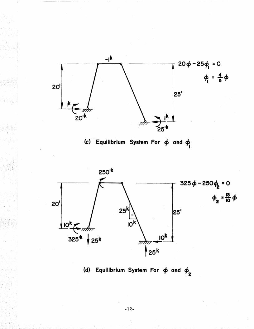
20¢ -25~ =0
4? = .±ofI 5
251
~k251k
(e) . Equilibrium System For .ci' and ~I
325 cI> - 250~ =0
~:I~~"'2 10 't'
251
(d) Equilibrium System For ci' and ep_ . 2
-12-

(e) Equilibrium System For II Shear Equation II
Fig. 5 Virtual Work Technique applied toThe Slope-Deflection Method
her..b.
2
.b.2
(a) Pin - Supported Arch
-13-
.b.2
b

(I-r) ~ he + (I-q) t hd
{I-di~
thd
(b) Equilibrium System For 8 and 82
(c) Equilibrium System For 8 and 81
Fig. 6 Virtual Work Technique applied toThe Mechanism Method
-14-

REFE-RENCES
1. Norris, C. H. and Wilbur, J. B.ELEMENTARY STRUCTURAL ANALYSIS, 2nd Edition, McGraw-Hill,New York, pp. 448-449, 1960.
2. Kinney, J. S.INDETERMINATE STRUCTURAL ANALYSIS, Addison-Wesley, Reading,Mass., pp. 495-497, 1957.
3. Neal, B. G.THE PLASTIC METHODS OF STRUCTURAL ANALYSIS, 2nd Edition,Wiley and Sons, New York, 1957.
4. Beedle, L. S.PLASTIC DESIGN OF STEEL FRAMES, John Wiley and Sons, NewYork, 1958.
5. Hodge, P. G., Jr.PLASTIC ANALYSIS OF STRUCTURES, McGraw-Hill, New York, 1959.
6. Massonnet, C. E. and Save, M. A.PLASTIC ANALYSIS AND DESIGN, Vol. 1, Beams a;nd Frames, Ginn,New York, 1965.
7 . NeaI, B. G.STRUCTURAL THEOREMS AND THEIR APPLICATIONS, Pergamon Press,London, 1964.
8. Drucker, D. C.INTRODUCTION TO MECHANICS OF DEFORMABLE SOLIDS, McGraw-Hill,New York, 1967.
-15-