tests of a large-sized reinforced-concrelfe slab …
TRANSCRIPT

TESTS OF A LARGE-SIZED REINFORCED-CONCRElfESLAB SUBJECTED TO ECCENTRIC CONCENTRATEDLOADS
By A. T. GOLDBSCK, Engineer of Tests, and H. S. FAIRBANK, Highway Engineer,Office of Public Roads and Rural Engineering, United States Department of Agriculture
INTRODUCTION
During the past five years a series of tests to determine the distributionof stress in reinforced-concrete slabs carrying concentrated loads hasbeen made by the Office of Public Roads and Rural Engineering. Theslabs included in the series have varied from 3 to 16 feet in span, and6 to 32 feet in width; and as a result of the tests much information hasbeen collected, practically all of which has been published at varioustimes.1 (I, 2, 3, 4, 6.)1
In all of these tests the concentrated load has been applied to thecenter of the slab, and sufficient data have been gathered to indicatethe manner and extent of stress distribution in slabs loaded in thismanner. In general, it may be said that the stress varies from a maximum immediately under· the load to a minimum at the extreme edges.The information as to the extent of the distribution has been made available for use in· the rectangular-beam theory of design by the determination of a value kno"vn as the "effective width," which, when substitutedfor the width b in the formulas, will lead to the design of slabs of dimensions conforming to those shown by the tests to be necessary. This ~
value is represented by that width of slab over which, if the stress wereconstant and equal to the maximum stress under actual conditions, theresisting moment would equal the resisting moment of a slab of the samedepth and full width in which the stress is naturally distributed. It hasbeen brought out in the previous papers that this effective width varieswith· the total width and span, the relation being approximately asexpressed in the table following.
1 GoLDBECK, A. T. TESTS OF REINFORCED CONCRETE SLABS UNDER CONCENTRATED LOADING. In Amer.Soc. Testing Materials, Proc., V. 13, p. 858-873,10 fig. 1913.--'rHE INFLUENCE OF TOTAL WIDTH ON THE EFFEC'l'IVE WIDTH OF REINFORC:~D-CONCRETE SLABS
SUBJECTED 1'0 CENTRAL CONCENTRATED LOADING. In Amer. Concrete Inst., Proc. v. 13, p. 78-88, 13 :fig.
1917.--and SMITH, E. B. tESTS OF LARGE REINFORCED CONCRETIC SLABS. In Amer. Concrete Inst.
Proc.• v. 12, p. 324-333, 7 fig. 1916.
---- TICsts OF THRICE LARGE-SIZED REINFORCED-CONCRETE SLABS UNDE:R CONCENTRATED LOADING. In Jour. Agr. Research, v. 6, no. 6, p. 205-234, 28 fig., pI. 26. 1916.
MCCORMICK, E. B. TEST OF A REINFORCED CONCRETE SLAB. In Amer. Concrete Inst. Proc., v. II, p.195-204, 8 fig. Discussion, p. 202-204. 1915.
J oumal of Agricultural Research,Washington, D. C.ks
Vol. XI, No. 10
Dec. 3,1917
KeyNo.D-IS

506 Journal of Agricultural Research Vol. XI. No. 10
Total width+span Effective width+span Total width+span Effective width+ Span
O. I 0 0 •••••••••• 0 0 ••••• 0 ••••••• 0 0 0 00 I I. I 0 •••• 0 0 0 0 ••••••••• 0 •• 0 • • • • • • •• o. 6702 •• 00 ••• 0 ••••••• 0.0. 0 0 • • • • • • • •• • 2 Io 2. 0 ••••• 0 • 0 00 ••••• 0 •• 0 •• 0 0 0 00.. .68· 3. 0 •• 0 •••• 0 • 0 0 ••• 0 • 0 •••••• 0 0 • • • • 28 Io 3 0 0 • 0 0 •••••• 0 •••••• 0 •• 0 ••• 0 0 • 0 0 0 70.4. 0 0 0 ••• 0 ••••••• 0 • 0 •••••• 0 0 0 • 0 0 • 37 Io 40 • 0 • 0 0 0 • 0 • 0 •• 0 •• 0 •• 0 ••• 0 • 0 0 • •• • 71
· 5 0 •••••••••••••••• 0 ••• 0 •• 0 o' 0 44 I. 50 0 ••••• 0 • 0 •• 0 0 • 0 •• 0 • • • • • • • • • •• • 72
· 6. . 0 •••• 0 • • • • • • 0 50 I. 6 0 • • •••••• 0 ••• 0 •• 0 0 •• 0 • 0 0 ••••• 0 0 72o 7 0 • 0 ••••• 0 ••••• 0 •••••••••••• 0 ., • 55 I. 7 . 0 ••• 0 •••••• 0 •• 0 • 0 •• 0 • • • • • • • •• • 72o 8 0 ••••• 0 •••••••••• 0 ••• 0 • o. • 58 10 8 0 •• 0 0 ••••••• 0 • • • • • •• • 72· 9 0 • 0 •••••• 0 ••••••••• 0 • • • •• • 62 I. 90 •••••••• 0 • 0 ••• 0 0 •••• 0 0 ••• 0 • o. • 72
Io O 0 •••••••• 00 ••••••• 0 0 ., • 6S 2. O .. 0 •••••••• o' ••• 0 ••••• 0 •••••• 0 • 72
The tests indicate that the above values can be used for spans up to16 feet, and they probably can be used for longer spans, although nolonger spans were tested.
However, these conclusions were drawn from the tests of slabs undercentrally applied concentrated loads only; and to make them properlyapplicable to the design of bridge slabs, which constantly are called uponto withstand concentrated loads applied near the parapet, it was recognized that the effect of eccentricity of loading must be determined.
With this end in view, another large-sized reinforced-concrete slabhas been constructed and tested recently at the Arlington ExperimentalFarm of the United States Department of Agriculture, and it is theobject of this paper to present the results of the test.
DESCRIPTION OF THE SPECIMEN
The specimen was made of machine-mixed concrete in the proportionsof 1 part of Portland cement to 2 parts of Potomac River sand and 4parts of Potomac River gravel. The sand was a good grade for use inconcrete and the gravel was clean, well-graded, and free from weakpebbles. A rather wet mix was used, and the mixing and placing weredone by experienced laborers at the Arlington Farm. As in the case ofthe other slabs tested, there was no attempt to make the concrete anybetter than it would be made in the field, but efforts were directed tosecure work thoroughly representative of that which might be obtainedunder field conditions.
The slab, which was built in place and supported by concrete abutments, was 32 feet in width, and 16 feet in span. Its total thicknesswas 14 inches, and its effective thickness 13 inches. It was reinforced,in the longitudinal direction only, with U-inch plain square rods, spacedsU inches apart, the sectional area of the steel being 0.75 per cent of thatof the concrete above its center of gravity. .
After the concrete was poured and while it still was soft, rows of boltswere set in the top surface of the slab, which, when withdrawn a fewdays later, left holes for the insertion of'lhe plugs and feathers to be usedfor splitting off sections of the slab as the test progressed.

Dec. 3, 191 7 Tests of a Large-Sized Reinforced-Concrete Slab 507
To provide definite points between which deformation readings mightbe taken, short brass plugs, drilled at one end with a No. 55 drill, werecemented in holes drilled for the purpose in the concrete, and similarNo. 55 drill holes were made in bared sections of selected reinforcingrods. At points where it was planned to take deflection measurementssteel plates were set in plaster of Paris on top of the slab. The locationsof these deformation and deflection points are shown graphically infigure I.
o (onc./"ote Oefor"mGf'iOl'l Po,,,,o :)t4o!C\ DeforMOtoon r~n+
.Oeflcc.tlor\ POInt
FIG. I.-Diagram of slab A-25. showing location of defonnation and deflection points.
METHOD OF TESTING
Loads were applied over an 8-inch bearing block by means of a hydraulic jack mounted between the slab and a specially calibrated chromenickel beam, the deflection of which, observed with the aid of an Amesdial, provided a means of measuring the load. This apparatus has beendescribed in detail in previously published papers.
Extensometer readings were made, between the points in both concrete and steel, with a 2o-inch Berry strain gauge. Deflection measurements also were taken over the steel plates by means of a special apparatus designed for measuring the wear of concrete roads.1
The slab was tested first with t4e load applied in the center of the fullwidth of 32 feet. Afterward successive sections were split off one side,making the width of the slab 29, 25,22, and finally, 18.5 feet. As the actualposition of the load remained unchanged, its position with respect to
1Go~DBECK. A. T. APPARATUS FOR MEASURING THE WEAR OF CONCRETE ROADS. In Jour. Agr. Research. v. s. no. 20, p. 951-954, I fig .• pI. 66. 1916.

5°8 ] ournal of Agricultural Research Vol. XI, No. IO
the slab width was thus rendered increasingly eccentric. The positionof greatest eccentricity was reached at the 'Width of 18.5 feet: in whichcase the load was applied at a point 16 feet from one edge and only 2.5feet from the other. Co:cresponding sections were then split off theother side of the slab, reducing the width to 15.5, 11.5,8.5, and 5 feet,respectively, the point of application of the load remaining 2.5 feet fromone edge. During this st~ge of the experiment the degree of eccentricity of the load was reduced with each section split off until finally inthe 5-foot width the load was again applied in the center. In figure1 the planes along which the slab was split are indicated by heavydashed lines.
Complete sets of deformation and deflection readings were made oneach width of slab, the repeated use of the slab cut to various widthsbeing made possible by the fact that the load applied at no time stressedthe specimen beyond its working stresses.
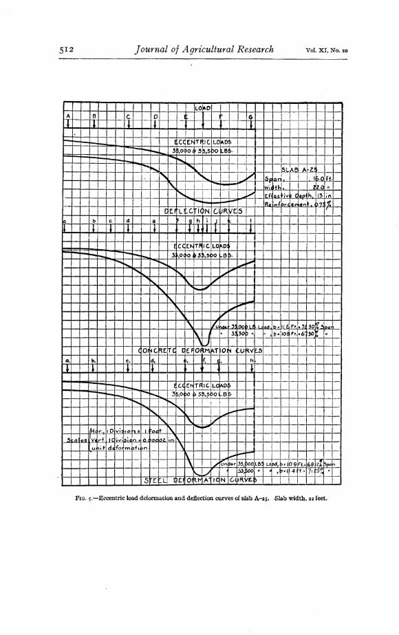
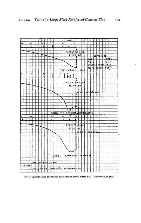
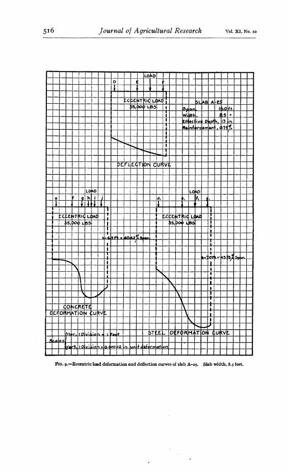
As will be noted by reference to figure I, the concrete and steel deformation points and the deflection plates were spaced along the middle sectionof the slab parallel to the supports. As this is the 'dangerous section of aslab under such loading, the measurements taken represent the maximumdeformation and deflection for the loads used at the various transversedistances from the point of application. The measurements have beenplotted to scale, as the ordinates of curves, whose abscissre are the distances between the points of measurements, and the results are shownin figures 2 to 10, inclusive.
}-ESULTS OF THE TESTS
As in the tests of centrally loaded slabs previously made, the curvesof deformation of concrete and steel have been used to determine values ofthe" effective ,vidth " of the slab for the various total widths and positionsof load. This is done by measuring the areas of the curves with a polarplanimeter and dividing these areas by the maximum ordinates, the resultsin each case being the value of the effective width corresponding to theparticular width of slab and position of load.
These values are shown on the respective curves. This method isbased on the assumptions that the straight-line theory of fiber-stressdistribution is applicable to slabs, and that the observed deformationsare proportional to the extreme fiber stresses in the concrete and steel,though it is realized that for various reasons it is impossible to translatethe deformations into fiber stresses.
The relation between the computed effective width and the totalwidth for the several widths of the single slab tested is shown by thesolid-line curve in figure II. As will be noted, it is conservativelydrawn· through the lower edge of the belt of points derived from theconcrete and steel deformation readings. It shows that the effective

Dec. 3, 191 7 Tests of a Large-Sized Reinforced-Concrete Slab 509
LCADA 8 C O· 1 f G H I J
~ I I 1 , I J I I..
,.....~~I--~ C N~E ~ LOAD l,.-I--I---~ io-.. ..-I--
-r-... r-... i'-o-... r>5, bo ~L65 ~~~
t---~...... --~~--DE I=-L f..( TIb~ C.UF VI
~ b e d e 9 h I J ~ I rY1 n o· t:
~ l I I 1 I 1 ! ! I t I • J~ I-- I-.... C N E~l OJ 0 ~ I--" ...--
""-- ---.......f"..,"""- r>5. bo t> Lk35 ~~
~ 1/101""" • II. IdFIt. s 171. ~.5 ~ c llOil
~ 1/~l/
CC N(R T bE. Fe IR,. A IC N Cl RJ E.
a. b. C, d, ~. f. ~, h. i , j. k.
I t I I ~ • ~ It
~( ~ 1 OJ 0Ii r-- '""- C N~~ ..--
"'"~ ~5. DO )L65 "l.oo"~ Ih. It. r' • 'rrZ. 0'. c loD"r,.
\ 1/
" .,.",
4~T [I- o f( )R Hi~T 01' ( UI~V .SL AF A·25
5 HI':} 16.0 f~.
wil:lH '2.( .. lil.fft .r-..•
I:'_~
Eli .d liv Clrzo' h 13 in. ISc. laiD Ic;.}IR. ~nfDr"'C en ~e,,1t !>.7.i~ 'ltD" It. I10' ,§ Oil : ( ocloo. in UI' .tc: I&fc 11",.. r.:.f "
FIG. 2.-Centralload deformation and deflection curves of slab A-2S. Slab width, 32 feet.

510 Journal of Agricultural Research Vol. XI, No. 10
LO'D
A e C 0 I 6 H I
I I I • I I I
f C( rfJ'l Tf 1(.. LQ~D ) "tf1III'".-'"--~ 3~,o po Ii'S 'J5 00 L8S. ""
,,-
""""~
I--. ...... ~~~-- '.",- ~
-~ ---r-.~~ _.... .....-- "'"
""......r-...~~ ~",,""
i'-"'- -*'~
~
Cf:.f LI C \C N COR liE.5.rI b c- d e ,
Q h l j k I "' n 0
I I I , I I I I l I I I • J- - --~ ""--- ~..... ..... ....... -...... ....... f C( E"Tf Ie. l,.O"O~ --~.--~....... ....... ---.........
~.........., 35.04 »0 ~5 5.5 )0 e~",.
-~",.-
....., ~,
" ~"~,
'",
~
"- '" :/ ~""'- ~"
'\ ,~ 1ft nd r ~ 5.0l~L ~.·L.. b to. 1'-4~I ~~ 'Pc'", I
II.::I:~OIuu D ;11-« • r~/'~J
II
i\.1cor~" ~t iTE (J E.f Of M~T 01~ 4 UI~V e.s
G, b G, d. I, f'. ~. h, i. j.I- ~ I J I ~ I
-~ ...r-- '-- ...;."",r-..... ....
~-I C( tt--Tf Ie LO 1'0 ~-....... ........ i'~ 3),OC o • .$ 5.5 po B)· ~ ---
........- --~I'-~ ' ....
/"..-~
""",,.....
~ -...-.\.. 1/ ...~SL IA~ ~-Z,5
, ' .... iJ ~~
'S· lol!'l 16.0 If~,
j
!Wi4 if., ~o.c • \ '1/. Efi r.c iVli I: IeOl 'h 13 in.
,j
ft. Inl: ore an en ).7~i~ ~ I - II • ",A ~ 12, IIF'i • r.§'.f ~z~ ~Dl!ln, , .. S J5e 0- . , ..,. II· fF"i a f.Z~!
'-/5 E. EL DE. OFtr~A 1< N C.I~R Ve:~
(.01' I Pi~ t.i 'r'\ I r- ot5c. ~185~ . -".,. .,1 pi .. lSI~n .0 00 ~o~ it1. loA ,it Ide 0,. matio~
FIG. 3.-Eccentric load deformation and de1lection curves of slab A-as- Slab width. 29 feet.

Dec. 3. J91 7 Tests of a Large-Sized Reinforced-Concrete Slab 51 I
LO"O
A B C 0 I f G H
~ I 1· ! I I .I---.--~ I C( r.~ Tf Ie LO~D~
~-~~~ -~-- .35,0 po &5 ~,s 00 t.B~. ~~-- ...... ~
......... ~ll...- ---...~- ~
~
.r---. ....... r---. -~ ......~ . .~r,--r--. r--- """""'- ----~
.[ [f LI-C 11'"1(~N C ~R ve:bIa b c. d e 4 h i j. I m
II I J I I I I ,I J 1 'If"""IoIo~, f C( E.fI Tf Ie LO~D ---~
~ro-~~ ......
.......~~JO )0 r,5 5,5 ~o-L5 Sr.....""~ .
' ....,~ ,,;'''
""~ " ~, t....,....~,- 'I'" ~~
. ""'"
" !/'
'" VI" IUI"\I ..,. ~5J OC LB Lc~d b.IO. F"t.1a6 .12 S.lGn.
~ " .. 155, ~oc • iii b-II.' f"t.• ~ 50 "'\ l/
COl~C ~E rTf [ E.I 01 M~T Ol~ U~V 50, b, e, d I " ~, h i l't . I 1 I I I ;
....... -- -~ r--.~ f C( £t- TF Ie: LO~o I)"-' r---~~ ....... r--...~ 3),0 ~o ~.5 ,,5 >0 .8 ).: -L- l..oi..-.-..
""'-~ "- ~",~ \\.
" """, ~r ~
ISL IAt: A-2. Ii " ,,~ ~, ,--Is, tn 1b.(J I~t. ~ ~
W·~tl i5.C It ~ 1/IJ::.f~ aG' ;v Opa1h 13 in.
,JUne ..,.. Ss,c bOI e..IOOcl ,b ~ I 4 t. 71 ~5· 5~~".
I';"" •7, lets ,~ II !i3,~~o to .. b ~ 1 .' It. 756t~
""""'-jIIII""
5~E.~L I~E ~O·~~~A I( N C'~R. ~f.5
It-f ,,.. I~'v 10"'\ « IF"ftll+
,C;rn !,,-~,
Vert Ie '\,,1 &,e n-::l o. ~oc oz in. ~,. ;+ ~ef ,,.. 'u~i ior
FIG. 4.-Eccentric load deformation and deflection curves of slab A·~S. Slab width. 2S feet.
23716°-17-5
512 ] ournal of A gricultural Research Vol. XI, No. 10
LOIt-OA 6 C 0 I G1 1 J J T
"-to-~~1-- ........ fCC Et- TF 1(. LO~D)-~~~ ..... 'sP.oc o(~ .5 ~)sPo B&·
,.....~~-- .........
~ !I'.~ "'"",I ! ~.L.~.f~ Z'
f"" j~ l,;' 15 In .. 16.0 Jr.~ I -~-
~
~+~'tv' 2Z.D ••
1'... J,,- f.1roc. i'll CeO' h 13 inI .... ,....",- I""-"" -~ ~"l ~.7.' ~RG brt en In
I [ E.f LI C. I(~N (.,IIJR.~f:5 f7
la b G d 1 0 g h i J I
rr T I I i ~ I tIl T
ECC E~T~ Ie lO~DIiiiiiiiiiiiiO~
~ -~ J.',O( ~~'4PO Be».~ ......'""""""~ o ~5
~'- ........, ....~
;" I
r"~......" ~
;Ii'
~~ ~ /1 I
~ -......~I\. --~I / ~, V
'\ ~ ,A.. ~lIlINJ.I\IJ .1 l...,. !.., ~ !11f. 1="+. 7, . liD ~ ~,., .., :
~ J " s~ so ~ 'I .' ) b= 10.t Ft.-6 .50:- IJ
'JCOl ~c. RE TE [E FO~M~T Ol~ UR.Y~5
Q. ". e. d. If. ~ . h.
1 1 l Il ~ l
~I--~~ f « E~Tf Ie. LC~Do~~ I'--~
~~ ..... 3~IO ~o ~5 ~.~~o 6~
~~ ~~ I 1~~ "\ ..,,~l--
j.oioioiI
~ " l/M ,.. vi 1;0 It r\. r--~
ID 10 n. ~.'~ ... ,...f, IC 'viL~; n it ol"ll)t in,l\.
u ,it d, fo, m )~; " \\ , ~ ......\ /~I'l
-Z%b".an~o..,. ,35" ,oOLe Lobd D-= ,b.9 Ff.= 68.
~ -' . .53, SOO 1\ fl t ~ ..,.4- L:· 71 ~S% It
:5 [, _L [ Ef Of~t" A Ie N c.tH\ IE. ;,
FIG. s.-Eccentric load deformation and deflection curves of slab A-2S. Slab width, 22 feet.
Dec. 3, 191 7 Tests of a Large-Sized Reinforced-Concrete Slab 513
U~AC
A B C 011 l I I
""- I~r-- r--..~ ... c r.~T RI( L< AC
--... I'---. r.......-... ~5, DO 't 65 Sl At: A 'l~r-- r--. I Is 10 Ib.O1ft~
........~ Wi~tl IB.I; tI
"'~ I lE.f~ ee i~ C1.01 h I~ in.r---...U Fb. Inf ore eO' en ~).7! .~
DE fl f:< TIO'" CUf Va b c d e q h I j
I I I I I 1T 111
1--__ [C (NT RH ll~A[
-~ r-... t"'-- .... 55,bo L~5.
l""'--.
""~"""" k al6f ft... i.'5. t~~ ·..-;;Illt\
~ I
r\. I
i\ I, I
~ """'~~'\.IJ
tc N~R T bE. rc RthA Ie N C\~R' r:-a, b. c, d, f, ,ca.
l ~ l II
r- """- I'--r--. C ( ~T ~I( L bA[~
........ 1"'-....1000.. ~5, DO ~ L~5
~ k II .0 ~+. '= 1:\0 lnr I~ i"'dl .
""~ I
" \\
"'" ~r--~
DTI E.I- D F(~R 1'1) TIO'" ( U ~V
,lHn 0' ISi.O : I I too
ISr. tllo ~1l\le t. 10 \1'1 ~ ;0. ":Ill booboe a'iIn. un i ~ e.f~ .ty'Q,"".I,!,n
FIF. 6.-Eccentric load deformation and deflection curves of slab A-2S. Slab width, 18.S feet.

Journal of Agricultural Research vol. XI, No. %0
LC~AD
,6 C 0 I I
1 t II
C ( ~T ~'( ~(A[
~ 1-0-1..... ~5, ~o PL8~ ,-!"""-oo r...... I f;.l ~8 A·~'
......,i Lc:; In t~o it.
"""'-, t Ivii 11+1- 1,15.5 If .
'~ I Eli cc. ...- Cl.t:lo1 h .3 in.~~
IR. "~ b,.. en c,.1t- t:l7. i-L
-t--1-1 .- LI
Df. FL f.~ TIK>~ CUf V
b e cI • 9 h i' j
l I I I J I I I:
C (I~T \Ie L(AO
-- -... --~ ~5t )Ol _LB5 I
""- I
"'- It • '.4 t·5Z.t:; 0% bpo,...
" I'\ I
'\~
\'1\.
I"- ,."
CC N( Rl T DE roC Rto A -Ie N Cl R' tb. <:. d. •• f a.I I 'I t ~ ~
IC f.' HT RIC U~"[
-~ r--. ~5't PO P L~5.........1""'-"",- t
~ I
r\. ~t &7·br. 1r 3. l l51.' SP,n-
f\ I-,I
.IHft . -' . • ! I f r...A' \ I
Sr. .,. Ill) '14 1: 110 iv' '0 .0.(~ 1)2 1\. \.I
I W'I ~+ q,f. r n ,n~ ;ft \ :'" I-
'J)T E~ DI F( )R MJ TIO~ CUJW
FIG. ,.-Eccentric load deformation and deflection curves of slab A·2S. Slab width, IS.S feet.

Dec. 3,191 7 Tests of a Large-Sized Reinforced-Concrete Slab 515
LCAD
d • , o h ; j
I J I J I II.
,-c. ~( ~T ~'( LC)A[
55. 00 PL 65 II
........ I h 1 5F t.• AI;. 8'1,' O~I •..::11"......... r---.., ......... :
~ ....... I
'" I
~ :\ I
:\ _J
"''''''''''CC N<R T~ pr. fO Rt- A Ie N Cl'R ,[,
c. d. ~- r. ~.I 'I t J
I( ( ~T RIC L( )A(
)5, 00 PL 65 II -
""" ......... : b .S F'1. A 1'1."'~ I""', •
'r\. I\ :i\ I
\ I1\ I
'"I
'--J,1 "'""f.. .... D f)R M T Ot ~ ( u \v ....
SL A~ A 2.)
'.5 '.0 11;.0it
114n . I O' Is;on .. I. F ~+ Wi tI- lLS ..
!s~ til", !§J £;~ &, I-Y CIPi h, .3 ;n.
l, e'" ~ I O. t!J on lie .oc oolt.. .l Inl~ d.'£o, n't It. 1'\ ita n4 or e" an ~.~ ;-1
FIG. S.-Eccentric load deformation and deflection curves of slab A"2S. Slab width, n.s feet.
516 Journal of Agricultural Research Vol. XI, No. 10
LO"O0
J!
rc ""f. ~T 1\IC L(~C i 5L AB A Z'~5. poe ) L~5 I lsi a" 10.0 'ft.
; Iwi~ .. U.S ..I Ef eG i~ f) 1mh, 13 ·Il.
: Ra nf 'rc err en 0751:I
"-- ......... :~ ......... I
......~~-
~
Of.. FL E.( T' 01' CUf VI
lO~D LO'Oe r Q h i j d. . f l ~ I
J J. I I I J • JI i
~c. E~T ~I( U~AC : ...C E.NT ~IC LC~ :5,~c ) L 65 I ~5, :>0- ) L.," I.
I
•Ioi.,"- I~Fl .I~-.. t1_ ,
II :
I I
: .. t~F to.-,___ II _
- --..~ I I
,'\ I
"- I
~ : i'... !\ I ~ I\ ) ,
I
'.....~/ \ I, ,
(0 ~CRE Tf 1\ I
[ E.f Of tM ~T O~l U~V~ ,I
~ I
"- .....~(HI ~. fO I'" 'LOn I Fo.~ ;iT ~E. ~ D f4)R M, T orI ( U \V~
~>L4 tl~,)
lVaH: .0 vi io h. 0.(~o pz; In· LlI\ +, ale r" cri on
:FIG. 9.-Eccentric load deformation and deflection curves of slab A-:zs, Slab width. 8.s feet.

Dec. 3~ 191 7 Tests of a Large-Sized Reinforced-Concrete Slab 51 7
LO"OI
~ I
CE.N trE: Rl 0) 0
I ~O,POl ~ Les •I
t ~ L~ B A· ""5I I 15~ 1.otr'1 Ib·OIlt.I I IWi ~+ ... ~.O II
~ ~ E.f'Ia.c. i'l r ~rn h l~ ~n
I I IR~ nf ,.c erlen ).'.1 ;~
i I II
I T
Dr. fL E.( TIPI' ( Uf VI
LO"O LOI\O
4 h i J ~ If.I & 1 1
I i f iC N trE R~ OJ D CI:'N rE. ~ L OJD
11>0, POl ~ L,,! I 11»0. t>O ) L 65 .•I J -'. I~ I I
,I I I
II
" lA'#, Ina 'G ~lt tJj I c._. 1_. I ".II
-, I ,*I•• A IQF· ~ '''.£
I I..~
II
I I I I
• I I I
: I TI
L I ~ I
\ I I :,!~
...u f I
~ : I
(0 ~C~ET£ l I
CEF OF M ~T 01.( Uf~VI ~ I,~ II
~H~I", oilvt! ~or : I Oft, 1+ Dr E. ... 01 f"4 DR MJ TIOt I Ul v::"4 t.:l D
Vert'J ID VI lon- p, 00 Z. n. ~" If d~ t"~ £Ii on
FIG. Io.-ce.ntralload deformation and deflection curves of slab A-2S. Slab width,s feet.

Journal of Agricultural Research Vot. XI, No. 10
width of the slab 16 feet in span and 32 feet in width under the centrallyapplied concentrated load was I 1.2 feet, and that this value remainedunaltered when one edge was split off, reducing the total width successively to 29, 25,"and 22 feet, although for these widths the load waseccentrically applied. When, however, the total width was reduced to·18.5 feet, it will be observed that the effective width fell off abruptly toa lower value, which was only slightly reduced by splitting off sectionsfrom the other edge, so as to reduce the total width to 15.5, 11.5 and 8.Sfeet, respectively. Finally, when the width was reduced to 5 feet, in
, LOAO
~----Jt,o_ -----------~~---~p..o'------__,'i4-----2.5.0'-------~ Ii4----.-' -- tZ.~--- --------t' I I!'t-----. -18.5,---- r---, I I I~b--.-c- f6·0d--~ ~ 19 In Ii fj~:;.;:.:;: ~,~. :~~'~.:~:{£~.': .. ~Z?~:~:·::~:~~· .~~~.•~ ..a~:·~J~:.Z:A·\.~:~;:.~~~··~.:~tt~:;~~~~~:,iJf.':.~~~~~?1~:~:-:4,~1::.:~~:~:~t~:~~~~~~:::.~1
t.-- --L -.L __l_ 15.5' ---..JNote: a-j R.~ref..tn+.O,.·,~;nClI .rCllb t 3ZFtI I. --L 11.5' I wld~ Sec.+jon~ 'j.h',l]"Jf(j,ab,bc.tt--- i---'-- --"'i cd,ondde were split eff ill the 'order'~ 1-- 8.5' --J named,and te~ts were f'T'lod. on
o &,seef on Cone,..t. RCAd,ru3s k.- 50' ---J the "emGi",n~ po,..trons,wtth thelC • • stoet • load in pos.t:on 05,.nDl.,ated.
10 t--+-+--+-~+--lI-+--+--+--l--+--+--+--I="'~II!::..f-",.",.-+-~-+I-"'-+---HE/-+[llI"""_4l-+-~-+--l--+--J-+--J.--l-ClI_· +-f--I--I
.. ,--- ,~~ j "",l "" II I • ~ n
~ et--t-+----+--+--+-iI-+-t----t;-o''9-·'t--f-+-t--+---t-=-i'=.wCIJIIII!J~rr_~_+___f___+__JI_+_1___l__1_-+_~_f_._+_I__+--:1! ,~ 0.•_ ." •••- :J~~
'%' ~..::;ll:':':'=::- i1 K:: ,,..,, "fl:: ! ..VI dii, ~.~ :; ~b 6 t-+--+--+-··-t--+--1~~~lJ-tt-+-+----t=-"'f'll..Xlf--'~Olf'L.1I~!.U4f'"~..Ii&-+----JI-+_1_-+--+--t--t--r-+--+-1
~ .A··.. •
~ 4 I--t-+--t-~AT-F-+--+--l--I~-+----h--f--.J---+-f----+----J--+-I--+--I--+--l--+--l:'-+--J.-~-+--'}---+--It '/lIJ/~ l t-i',,"""":/'7fL-t--t--+--+--i-+--if-+-t-......j--t-t--t-+-t-'--+-~I---+-+---f--+-+---i--+-+--+-+---f--+-f
V'o· 14
WIDTH O~ ~LA8r .'''' n.E.T
O' I
FIG. II.-eurve showing effective width v. width of slab.
which case the load again was applied at the center, another falling offin the value of the effective width is indicated.
The curves superimposed on the curve of observed values representwhat seems to be a logical interpretation of the somewhat peculiarshape of the curve. The regular dash-line curve is a graph of the valuesof the effective width ,for various total widths of a I6-foot slab subjectedto a concentrated central load. It is based upon the values given inthe foregoing table, showing the variation of €(ffective width in slabsloaded in that manner. The dotted-line curve is based upon the assumption that the effective width of an eccentrically loaded slab (be) is equalto that (be) of a centrally loaded slab of the same total width when thedistance from the load to the nearer edge (D) is greater than one-half

Dec. 3, 191 7 Tests of a Large-Sized Reinforced-Concrete Slab 519
the effective width of the centrally loaded slab, but that when D isbe . be
reduced to less than - the corresponding value of (be)=-+D. The2 2
approximate coincidence of this curve with that of the test valueswould seem to confirm the truth of the assumed relation. Unfortunately, however, the results can not be regarded as entirely conclusive,owing to the fact that the recent test involved only one span lengthand yielded only two points on the critical part of the curve betweenthe total widths of 18 and 22 feet. It is hoped that this point will becleared up' by further tests.
CONCLUSIONS AFFECTING THE DESIGN OF SLABS
To provide against the frequently realized condition of a heavy concentrated load applied near the parapet, the test conclusively showsthat the resisting moment required in the portion of a bridge slab nearthe outer edges is greater than that which is necessary in the centralportion.
Further than this, if the relation indicated above be verified andshown to include other span lengths, it would seem that in designing aslab the necessary allowance for the concentrated load near the outeredge can be made very simple in the following manner:
(1) Use the formul~s for narrow rectangular beams, substitutingfor the breadth (b) the value obtained from the foregoing table forcentral concentrated loads; (2) determine the loss in effective widthdue to the assumed eccentricity of the load; and (3) supply the deficiency by designing the curb of the parapet to provide a resisting mOlnentequal to that of a slab of width equal to the loss in effective "'idth dueto eccentricity, making allowance for the greater stiffness of the sectionunder the parapet. Thus, suppose a slab of 16-£00t span and 20-£00twidth is to be designed to carry a concentrated load of 20,000 poundsapplied at a point 4 feet from one edge, then
Total width 20
Span - I6 1.2 5
from the table for central concentrated loading, the effective width = 0.69 X
16 feet = 11.04 feet. Consider the load of 20,000 pounds to be carried bya width of 11.04 feet, use the ordinary ·formulre for rectangular-beamdesign and determine the effective depth of the slab and the area ofsteel required. Now, by the relation indicated above, determine .theeffective width with the load in the critical position 4 feet from oneedge, then
the difference between the values of be and be is 11.04 - 9.52 = 1.52 feet.
520 Journal of Agricultural Research Vol. XI, No. 10
Therefore, the curb of the parapet should be so designed that it willhave a resisting moment equal to that of a width of 1.52 feet of the slab,making allowance for the greater stiffness of the parapet section.
In constructing slabs designed in this manner it is needless to saythat the curb of the parapet must be added before the concrete of theslab has taken initial set.