rc2 reinforced concrete slab example - aashtoware bridge design … - rc slab... · 2018-09-17 ·...
TRANSCRIPT
AASHTOWare BrR/BrD 6.8
Reinforced Concrete Structure Tutorial RC2 – Reinforced Concrete Slab Example

RC2 - RC Slab Example
Last Modified: 9/14/2018 1
27'-0"
Top Row: 27-#5's @12"Bottom Row: 54-#9's @ 6"
24'-0" 1'-6"1'-6"
18" slab thickness, consider ½”
sacrificial wear thickness#5
#5
1.5" clr.
2.0" clr.
RC2 - Reinforced Concrete Slab Example
30'-0"9"9"
Elevation
Typical Section
Material Properties
Slab Concrete: Class A (US) f'c = 4.0 ksi, modular ratio n = 8
Slab Reinforcing Steel: AASHTO M31, Grade 60 with Fy = 60 ksi
Parapets
Weigh 300 lb/ft each. If slab cross section entered as 12" wide strip, member load
due to parapets will be (2*300 lb/ft)/27' = 22 lb/ft.
#5
#9
6" (Typ)
CL Brg CL Brg

RC2 - RC Slab Example
Last Modified: 9/14/2018 2
BrR and BrD Training
RC2 - Reinforced Concrete Slab Example
Topics Covered
• Single span reinforced concrete slab
• Sacrificial wear thickness for a slab
• Entered using both cross-section based and schedule based input methods
From the Bridge Explorer create a new bridge and enter the following description data:
Close the window by clicking Ok. This saves the data to memory and closes the window.

RC2 - RC Slab Example
Last Modified: 9/14/2018 3
To enter the materials to be used by members of the bridge, click on the to expand the tree for Materials.
The tree with the expanded Materials branch is shown below:

RC2 - RC Slab Example
Last Modified: 9/14/2018 4
To add a new concrete material, click on Concrete in the tree and select File/New from the menu (or right mouse
click on Concrete and select New).
Add the concrete material by selecting from the Concrete Materials Library by clicking the Copy from Library
button. The following window opens:
Select the Class A (US) material and click Ok.

RC2 - RC Slab Example
Last Modified: 9/14/2018 5
The selected material properties are copied to the Bridge Materials – Concrete window as shown below.
Click Ok to save the data to memory and close the window.

RC2 - RC Slab Example
Last Modified: 9/14/2018 6
Add the following reinforcement steel in the same manner.
We do not need to define any beam shapes since we are using a reinforced concrete slab. The slab will be entered
later using two different methods, as a cross section and as a schedule based member alternative.
Reinforced concrete slab could be entered as Girderline Superstructure Definitions in BrR/BrD. Since we will not
be defining a Structure Typical Section for a girderline structure, we do not need to define any appurtenances. The
dead load due to the appurtenances will be entered later as member loads.
The default impact factors, standard LRFD and LFD factors will be used so we will skip to Superstructure
Definition. Bridge Alternatives will be added after we enter the Superstructure Definition.

RC2 - RC Slab Example
Last Modified: 9/14/2018 7
Double click on SUPERSTRUCTURE DEFINITIONS (or click on SUPERSTRUCTURE DEFINITIONS and
select File/New from the menu or right mouse click on SUPERSTRUCTURE DEFINITIONS and select New from
the popup menu) to create a new structure definition.
Select Girder Line Superstructure and the Structure Definition window will open. Enter the appropriate data as
shown below:
Click on Ok to save the data to memory and close the window.

RC2 - RC Slab Example
Last Modified: 9/14/2018 8
The partially expanded Bridge Workspace tree is shown below:
We now go back to the Bridge Alternatives and create a new Bridge Alternative, a new Structure, and a new
Structure Alternative as we did previously.

RC2 - RC Slab Example
Last Modified: 9/14/2018 9
The partially expanded Bridge Workspace tree is shown below:

RC2 - RC Slab Example
Last Modified: 9/14/2018 10
Click Load Case Description to define the dead load cases. The completed Load Case Description window is shown
below.

RC2 - RC Slab Example
Last Modified: 9/14/2018 11
Describing a member:
Open the Member window by double clicking on Member in tree. Fill in the window with the following
information. If we press F1 while this window is active, the Help topic for the Member window will be displayed.
This help topic tells us that girder spacing and member location are not required for a slab member so we will not
enter any data for those items.
The first Member Alternative that we create will automatically be assigned as the Existing and Current Member
alternative for this Member.

RC2 - RC Slab Example
Last Modified: 9/14/2018 12
Double-click Member Loads to open the Member Loads window. This structure has 2 parapets each weighing 300
lb/ft. We are defining a 12” wide strip of slab as our member, and the width of the bridge cross section is 27 ft. So
the parapet load applied to this member will be (2*300 lb/ft)/27’ = 22 lb/ft.

RC2 - RC Slab Example
Last Modified: 9/14/2018 13
Cross Section Based Member Alternative
This portion of the example deals with creating a cross section based member alternative.
Defining a Member Alternative:
Double-click MEMBER ALTERNATIVES in the tree to create a new alternative. The New Member Alternative
dialog shown below will open. Select Reinforced Concrete for the Material Type and Reinforced Concrete Slab for
the Girder Type.
Click Ok to close the dialog and create a new member alternative.

RC2 - RC Slab Example
Last Modified: 9/14/2018 14
The Member Alternative Description window will open. Enter the appropriate data as shown below. AASHTO
Article 3.24.4 states that concrete slabs designed in accordance with AASHTO Article 3.24.3 shall be considered
satisfactory in bond and shear so we will select the LFD Ignore shear checkbox under the Shear computation
method.
We are considering ½” of our slab to be a sacrificial wear thickness. When we enter the cross section properties
later, we are going to enter the effective slab thickness. We need to enter an additional load here on the member
alternative window to account for the ½” sacrificial wear.
(½”)/12 x 0.150 kcf = 0.0063 k/ft

RC2 - RC Slab Example
Last Modified: 9/14/2018 15
We can now enter the LRFD live load distribution factors for this member. Open Live Load Distribution window
and select LRFD tab. Click Compute from Typical Section button, enter values as below in the pop up window.
Click Continue button, BrR will compute LRFD live load distribution factors, click Ok button to close analysis
window.

RC2 - RC Slab Example
Last Modified: 9/14/2018 16
The Live Load Distribution window will look like below.

RC2 - RC Slab Example
Last Modified: 9/14/2018 17
We can now create a new cross section by double-clicking on Cross Section in the tree. The completed Cross
Section window is as follows. Note that we are entering the effective slab thickness here.
The reinforcement for the section is shown below.
Distance from
the Top of Slab is
measured from the
top of the effective
slab thickness.

RC2 - RC Slab Example
Last Modified: 9/14/2018 18
The cross section is now applied over the length of the member using the Cross Section Ranges window as shown
below:
Shear Reinforcement Ranges and Bracing Ranges are not applicable to this member so we will not enter any data in
these windows. We also do not need to define any Points of Interest since we will not be overriding any information
we have entered.
The description of this structure is complete.

RC2 - RC Slab Example
Last Modified: 9/14/2018 19
The member alternative can now be analyzed. To perform LRFR rating, select the View Analysis Settings button on
the toolbar to open the window shown below. Click Open Template button and select the LRFR Design Load Rating
to be used in the rating and click Ok.

RC2 - RC Slab Example
Last Modified: 9/14/2018 20
Next click the Analyze button on the toolbar to perform the rating. When the rating is finished you can review the
results by clicking the View analysis Report on the toolbar. The window shown below will open.

RC2 - RC Slab Example
Last Modified: 9/14/2018 21
Schedule Based Member Alternative
This portion of the example deals with creating a schedule based member alternative. Create a new reinforced
concrete member alternative for our member “Typical Slab Member” and enter the following data.
Since we are describing a slab member and ignoring the shear in the slab the following discussion does not affect
this particular example. However, it is an important item to be aware of when you are considering shear in the
member so we will review it now.
For a schedule based reinforced concrete member, it is important to enter a value for the End Bearing Locations in
this window. This data describes the distance from the physical end of the beam to the centerline of the end
bearings. It is important for us to enter this value here so that when we assign bar mark definitions to the
reinforcement profile we can start our bars to the left of the first support line and to the right of the last support line.

RC2 - RC Slab Example
Last Modified: 9/14/2018 22
If our bars start to the left of the first support line and to the right of the last support line, BrR/BrD will consider the
bars to be partially developed at the centerline of the bearing. Then the analysis engine will be able to compute the
“d” distance from the extreme compression fiber to the centroid of the tension reinforcement. This “d” value is
required to compute the shear capacity of the section. If the rebar starts at the centerline of the bearing, it will be
considered as zero percent developed at this point so a “d” distance cannot be computed and the shear capacity of
the beam will be zero.
We can now enter the live load distribution factors. If you have created the cross section based member alternative
in this example, you can copy the distribution factors from the cross section member alternative to the schedule
based member alternative. Right click the “Live Load Distribution” label under the cross section member
alternative and select “Copy” from the menu. Then right click the “Live Load Distribution” label under the schedule
based member alternative and select “Paste”. If you have not entered cross section based member alternative, enter
the following distribution factors by hand.
Standard:

RC2 - RC Slab Example
Last Modified: 9/14/2018 23
LRFD:
Open Live Load Distribution window, LRFD tab. Click Compute from Typical Section button, enter values as
below in the pop up window.
Click Continue button, BrR will compute LRFD live load distribution factors, click OK to close the analysis
window. Live load distribution factors will be calculated as below.

RC2 - RC Slab Example
Last Modified: 9/14/2018 24
Deflection distribution factors.

RC2 - RC Slab Example
Last Modified: 9/14/2018 25
Moment and shear have the same following distribution factors.
Before we can describe the girder and reinforcement profile for our member alternative, we should first define our
Bar Mark Definitions. Bar Mark Definitions are used to define the longitudinal flexural reinforcement in schedule
based reinforced concrete members. This bridge uses the following bar mark definitions:

RC2 - RC Slab Example
Last Modified: 9/14/2018 26

RC2 - RC Slab Example
Last Modified: 9/14/2018 27
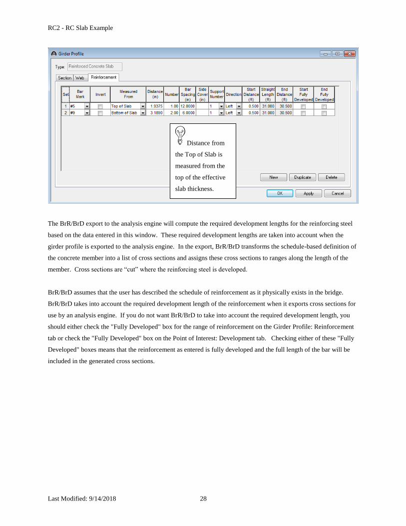
We are now ready to describe the Girder Profile:
RC2 - RC Slab Example
Last Modified: 9/14/2018 28
The BrR/BrD export to the analysis engine will compute the required development lengths for the reinforcing steel
based on the data entered in this window. These required development lengths are taken into account when the
girder profile is exported to the analysis engine. In the export, BrR/BrD transforms the schedule-based definition of
the concrete member into a list of cross sections and assigns these cross sections to ranges along the length of the
member. Cross sections are “cut” where the reinforcing steel is developed.
BrR/BrD assumes that the user has described the schedule of reinforcement as it physically exists in the bridge.
BrR/BrD takes into account the required development length of the reinforcement when it exports cross sections for
use by an analysis engine. If you do not want BrR/BrD to take into account the required development length, you
should either check the "Fully Developed" box for the range of reinforcement on the Girder Profile: Reinforcement
tab or check the "Fully Developed" box on the Point of Interest: Development tab. Checking either of these "Fully
Developed" boxes means that the reinforcement as entered is fully developed and the full length of the bar will be
included in the generated cross sections.
Distance from
the Top of Slab is
measured from the
top of the effective
slab thickness.

RC2 - RC Slab Example
Last Modified: 9/14/2018 29
The following shows the cross sections and cross section ranges that are generated for our example when we analyze
the member alternative.
BrR/BrD computes the development length of the bars as ld. The bars are fully developed at the ld distance from the
end of the bar.
BrR/BrD assumes the reinforcement develops in the bar in a linear fashion, starting with 0% development at the bar
end and 100% development at the point of full development (ld)
Three cross sections are generated in this example. At 0.0’, the #5 bar is 28.6% developed and the #9 bars are
15.8% developed. These percentages are found as follows (note that the bars start 6” to the left of the centerline of
the bearing):

RC2 - RC Slab Example
Last Modified: 9/14/2018 30
#5 bar 0.5’/1.75’ = 0.286* 1 bar = 0.286 bar
#9 bar 0.5’/3.1625’ = 0.158 * 2 bars = 0.316 bars
This cross section is applied from the 0.0’ start of the member alternative to 1.25’ where the #5 bar is fully
developed.
A similar procedure is followed at 1.25’ which is where the #5 bar is fully developed and at 2.66’ which is where the
#9 bars are fully developed.

RC2 - RC Slab Example
Last Modified: 9/14/2018 31
If we select “F1” while the Reinforcement tab is open, the BrR/BrD help topic for this window will open as shown
below. This help topic contains very important information regarding the data on this window and it should be
thoroughly reviewed prior to using the schedule based reinforcement features in BrR/BrD.

RC2 - RC Slab Example
Last Modified: 9/14/2018 32
This help topic contains links to several other useful topics that should be reviewed prior to defining schedule based
reinforcement in BrR/BrD. The “Export of Schedule Based Reinforced Concrete Members” topic contains the rules
and assumptions BrR/BrD uses when exporting schedule based reinforced concrete members to the analysis engine.
RC2 - RC Slab Example
Last Modified: 9/14/2018 33
The BrR/BrD export will also check the actual lap lengths of schedule based reinforcement against required lap
lengths and present this information to the designer for their evaluation. BrR/BrD considers bars to be lapped if the
vertical distance to their centroids is equal or if their clear cover is equal and the bars overlap along the length of the
member. We do not have any lapped bars in this example.
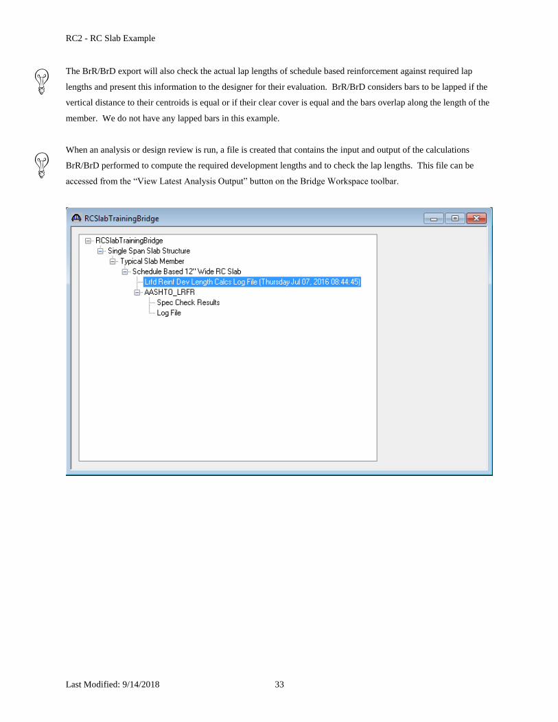
When an analysis or design review is run, a file is created that contains the input and output of the calculations
BrR/BrD performed to compute the required development lengths and to check the lap lengths. This file can be
accessed from the “View Latest Analysis Output” button on the Bridge Workspace toolbar.

RC2 - RC Slab Example
Last Modified: 9/14/2018 34
A schematic view of the reinforcement profile is available while the “Girder Profile” label is selected.

RC2 - RC Slab Example
Last Modified: 9/14/2018 35
We are now ready to analyze our schedule based member alternative. The following results are for an LRFR
analysis.

RC2 - RC Slab Example
Last Modified: 9/14/2018 36
An LRFD design review of this girder for HL93 loading can be performed by BrD LRFD. To do LRFD design
review, enter the Analysis Settings window as shown below:

RC2 - RC Slab Example
Last Modified: 9/14/2018 37
BrD LRFD analysis will generate a spec check results file. Click on tool bar to open the following window. To
view the spec check results, double click the Spec Check Results in this window.

RC2 - RC Slab Example
Last Modified: 9/14/2018 38
The Spec Check Results match the following results from the cross section based member alternative.