testo easyemission software 0360... · a. intended purpose the testo easyemission software adds...
TRANSCRIPT

Instruction manual en
testo easyEmissionSoftware

General InformationThis documentation includes important information about the features and application of the product. Please read this documentation through carefully and familiarise yourself with the operation of the product before putting it to use. Keep this document to hand so that you can refer to it when necessary.
This documentation describes the testo easyEmission software with the program language English - GB.
The range of functions of the software depends on the country version of the measu-ring instrument connected and on the number and kind of instrument types for which the software has been enabled via licence key. The descriptions in this document apply to the complete enabling of all instrument types.
SymbolsSymbol Meaning
Identifies particularly important information.
Text Text appears on the instrument display or PC monitor
* Data refers to standard mouse configuration (left button: selects, right button: context menu)
TrademarksMicrosoft and Windows are registered trademarks of the Microsoft Corporation in the USA and/or other coun-tries.Intel and Pentium are registered trademarks of the Intel® Corporation in the USA and / or other countries.Other trademarks or product names are the property of the respective owner.
General Information2

ContentGeneral Information ...................................................................................... 2
Content ......................................................................................................... 3
A. Intended Purpose ................................................................................ 6
B. Using software ..................................................................................... 7B.1 System requirements .................................................................... 7B.2 Installing software ......................................................................... 8B.3 Starting the software ..................................................................... 8B.4 Setting up testo 335, testo 340 connection .................................. 9B.5. Setting up testo 338 connection .................................................. 10B.6 Setting up testo 350 S/M/XL connection .................................... 11B.7 Setting up testo 350 connection ................................................. 13
C. Operation ............................................................................................ 16
D. Application example .......................................................................... 17
E. Functions ............................................................................................ 19E.1 Enhance licence ............................................................................. 19E.2 General ....................................................................................... 19
E.2.1 Previous module ...................................................................... 17E.2.2 Initial page ............................................................................... 17E.2.3 Exit .......................................................................................... 20
E.3 Folder ......................................................................................... 20E.3.1 Search folder ............................................................................ 20E.3.2 Show folder ............................................................................. 21
E.3.2.1 Address ............................................................................................. 22E.3.2.2 List of locations ................................................................................. 22
E.3.3 Change data folder .................................................................. 23E.3.4 Insert new folder ...................................................................... 23E.3.5 Import data folder .................................................................... 23
Content 3

E.4 Locations .................................................................................... 25E.4.1 Show measure locatioin data .................................................... 25
E.4.1.1 Location, Owner file, Installation, Flow data ....................................... 25E.4.1.2 Measurements ................................................................................. 26
E.4.2 Change measure locations data ............................................. 27E.4.3 Insert new location .................................................................. 27
E.5 Measurements ............................................................................ 28E.5.1 Search measurement ............................................................... 28E.5.2 Display measurement data ...................................................... 29
E.5.2.1 Information ........................................................................................ 29E.5.2.2 Graphics ............................................................................................ 30E.5.2.3 Measure values ................................................................................. 31E.5.2.4 Data sheet ......................................................................................... 32
E.6 Measure types ........................................................................... 33E.6.1 Manage measure types ........................................................... 33E.6.2 Define logger programme ........................................................ 34E.6.3 Formula builder ....................................................................... 35E.6.4 Report design ......................................................................... 36
E.6.4.1 Field, Font, Border, Page ................................................................... 38E.6.4.2 Editor ................................................................................................ 39
E.7 testo 335/340, testo 338, testo 350 S/M/XL, testo 350 ............... 40E.7.1 Transmit measure locations ..................................................... 40
E.7.1.1 Measure locations on PC ................................................................... 40E.7.1.2 Measure locations on instrument ....................................................... 41
E.7.2 Transmit logger programmes ................................................... 42E.7.3 Download measurement data ................................................. 42E.7.4 Online measurement ............................................................... 43
E.7.4.1 Measure values, Display, Chart .......................................................... 44E.7.4.2 Display order ..................................................................................... 45E.7.4.3 Instrument control ............................................................................. 45
E.7.5 Configure testo 335/340, testo 350 S/M/XL, testo 350 ............ 46E.7.5.1 Measuring instruments (testo 350 S/M/XL .......................................... 47E.7.5.2 Show configuration data /Change configuration ................................ 48
E.7.6 Manage instrument groups (only testo 350 S/M/XL and testo 350) ................................................................................ 50
Content4

E.8 Settings ...................................................................................... 51E.8.1 Data sheet designer ............................................................... 51
E.8.1.1 Field, Font, Border, Page .................................................................... 52E.8.1.2 Editor ................................................................................................ 53E.8.1.3 Preview ............................................................................................. 53
E.8.2 Configuration ........................................................................... 53E.8.2.1 Instruments ....................................................................................... 53E.8.2.2 Initial page ......................................................................................... 53E.8.2.3 Units .................................................................................................. 54E.8.2.4 Special location data ......................................................................... 54E.8.2.5 Programme ....................................................................................... 54E.8.2.6 Own data .......................................................................................... 54E.8.2.7 Color scheme .................................................................................... 54E.8.2.8 Software update ................................................................................ 54E.8.2.9 Language ........................................................................................... 55E.8.2.10 Backup .............................................................................................. 55
E.8.3 Information .............................................................................. 55E.9 Database .................................................................................... 56
E.9.1 Full backup .............................................................................. 56E.9.2 Incremental backup ................................................................. 56E.9.3 Restore database .................................................................... 56E.9.4 Repair and compact ................................................................ 56
F. Questions and answers ............................................................ 57
G. Appendix .................................................................................... 58
Content 5

A. Intended Purpose The testo easyEmission software adds many useful functions to the testo 335, testo 340, testo 350 S/M/XL and testo 350 measuring instruments:- Instrument configuration via software.- Folder, location and measurement data management.- Data import from and data export to the measuring instrument. - Data export to Microsoft Excel®.- Graphic and tabular presentation of measurement data.- Online measurement.- Sets up, saves and prints measurement protocols from imported data.
A. Intended purpose6

B. Using software
B.1 System requirementsOperating system
The software can be run on the following operating systems:
- Windows® Vista
- Windows® 7
- Windows® 8
- Windows® 10
- Others: On request
Computer
The computer must meet the requirements of the corresponding operating system. The following requirements must additionally be fulfilled:
- Interface USB 2.0 or higher
- Internet Explorer 5.0 SP1 or higher
- Hard drive (min.): 150MB free memory
- Microsoft® .Net-4-Framework: 2GB
The testo easyEmission Software automatically synchronizes date and time to the bus subscribers. If Control Unit and meas. box have not been synchronized to the same date and time, the settings of the Control Unit will automatically be used! If a system consisting of Control Unit, meas. box and testo easyEmission Software is to be synchronized, the Control Unit must first be adjusted / connected with testo easyEmission Software and subsequently the meas. box.
B. Using software 7

B.2 Installing softwareAdministrator rights are required in Vista and Windows 7, Windows® 8 and Windows®
10 to install the program.
Once installed, input of a licence key is required. Without this input, the software will only run as a demo version with a limited range of functions (time limit of 30 days). When the software is first started, a window automatically appears for you to enter the licence key. 1 Insert CD.
If the installation program does not start automatically:
Start Setup.exe file ( double click) from the CD-directory (access via My Compu-ter or Windows Explorer).
2 Follow the instructions in the installation program.
- testo easyEmission software is installed.
- testo 350-data bus-Controller software is installed. It sets up the connection between testo 350 S/M/XL oder testo 350 and PC via the USB data bus controller.
B.3 Starting the software Programs Testo testo easyEmission software
- The program is opened. The program language corresponds to the operating system language.
- When the software is first started, a window appears for you to enter the licence key.
Enter licence key (found on inside of CD packaging). [OK]
The range of functions of the software depends on the country version of the analy-ser connected and on the number and kind of instrument types for which the soft-ware has been enabled via licence key. To enter additional licence keys, refer to Enhance licence, p. 17.
B. Using software8

B.4 Setting up testo 335, 340 connec-tion
The analyser switches to the Slave Mode during data transfer; the analyser operating buttons are disabled in this mode. Once data is no longer being transferred the Slave Mode is stopped and the analyser can be controlled via the control buttons, as nor-mal.
Close the software before you end an existing connection between the testo 335, testo 340 and the PC, otherwise this can lead to program crashes.
Connection via USB-cable
To connect testo 335, testo 340 to a PC the “connection cable PC / instrument 0449 0047” is required. Alternatively, the testo 335 can be set up via an IrDA interface.
1 Connect cable to USB connection socket in the PC.
2 Connect cable to USB socket in measuring instrument.
3 Switch on instrument ( ).
Connection via IrDA interface
See Configure testo 335/340, testo 350 S/M/XL, testo 350, p.44.
Connection via Bluetooth
The Bluetooth module on the PC and the Bluetooth module in the testo335, testo 340 must be activated (Bluetooth®-Symbol in der Taskleiste: blau = an, grau = aus).In addition to this, a Bluetooth connection between the measuring instrument and the PC must be set up.
The connection is set up automatically via a Bluetooth assistant. This is started as soon as the Bluetooth interface is selected in the configuration of the testo 335, testo 340, see Configure testo 335/340, testo 350 S/M/XL, testo 350, p.44.
Depending on the Bluetooth® module of the PC the input of a password or main key may be required for device recognition. For all Testo instruments this is: 1234.
The status of the Bluetooth connection is displayed via the Bluetooth symbol in the task bar (green: connected, white: not connected).
B. Using software 9

B.5 Setting up testo 338 connectionData transfer to the testo easyEmission software is only possible for instruments with Bluetooth® (article no. 0632 3382). Please read the instruction manual for the testo easyEmission software (0970 0360).
The measuring instrument switches to Slave Mode while data is being transferred; the instrument‘s control keys are disabled in this mode. Once data is no longer being transferred, Slave Mode is exited and the measuring instrument can be controlled via
the control keys as normal.. Exit the software before terminating an existing connection between the testo 338 and the PC, otherwise the program might crash.
Connection via Bluetooth®
The Bluetooth® module on the PC and the Bluetooth® module in the testo 338 must both be activated.
The connection is set up automatically via a Bluetooth® wizard.
Depending on the Bluetooth® module used on the PC, the input of a password or main key may be required for device recognition. For all Testo instruments this is: 1234.
The status of the Bluetooth® connection is indicated by the Bluetooth® icon in the task bar (green: connected, white: not connected).
B. Using software10

B.6 Setting up testo 350 S/M/XL connection
Connection problems and loss of measurement data can occur when the energy saving or standby mode in your PC is activated. These functions should therefore be switched off.
The analyser switches to the Slave Mode during data transfer; the analyser operating buttons are disabled in this mode. Once data is no longer being transferred the Slave Mode is stopped and the analyser can be controlled via the control buttons, as nor-mal.
If the connection is interrupted without stopping the software, testo 350 remains in Slave Mode. Do the following to deactivate Slave Mode:
.
Close the software before you end an existing connection between the testo 330/335 and the PC, otherwise this can lead to program crashes.Connection via serial inter-face
Connection via serial interface
Serial connection is set up using a testo 350 S/M/XL Control Unit. Only one Cont-rol Unit can be connected to the measurement system.
For serial connection of testo 350 S/M/XL to a PC, the “PC connection cable/ 0409 0178 instrument” is required.
1 Connect connection cable to a serial connection socket in the PC.
2 Connect connection cable to the RS 232 socket of the Control Unit.
3 Switch on measuring instrument ( ).
Connection via USB serial adapter
USB serial connection is set up using a testo 350 S/M/XL Control Unit. Only one Control Unit can be connected to the measurement system.
For USB serial connection of testo 350 S/M/XL to a PC, the “PC connection cable/ 0409 0178 instrument” an USB-serial adapter is required.
1 Connect USB-serial adapter to a serial connection socket in the PC.
2 Connect connection cable to the RS 232 socket of the Control Unit.
3 Connect USB-serial adapter with connection cable
4 Switch on measuring instrument ( ).
B. Using software 11

Connection via Bluetooth
The Bluetooth® module on the PC and the Bluetooth® module in the testo 350 S/M/XL must both be activated.
The connection is set up automatically via a Bluetooth® assistant. This is started as soon as the Bluetooth® interface is selected in the configuration of the testo 350 S/M/XL, see Configure testo 335/340, testo 350 S/M/XL, testo 350 , p.44.
Depending on the Bluetooth® module of the PC the input of a password or main key may be required for device recognition. For all Testo instruments this is: 1234.
Connection via USB data bus controller
USB connection is set up directly to the meas. boxes via the data bus controller. No Control Unit should be connected to the measurement system.
Before connecting to a bus system, all analyzer units must first be equipped with the identical country version and firmware version.
Prior to commissioning a bus system, the bus address, bus rate, application and measuring location must be configured separately in each analyzer unit.
The USB data bus controller is a HighPower instrument, an additional USB Hub may be required.
1 Connecting the meas. box to the data bus controller: connect instrument plug to DATA socket of meas. box, connect serial connection plug to Channel 1 socket in data bus controller.
2 Connecting USB data bus controller to PC: connect USB plug (Type B) to USB socket in data bus controller, connect USB plug (Type A) to a USB socket in the PC.
3 Set up power supply in meas. box.
4 Start software testo 350 data bus controller under Start > Programms > testo > testo 350 data bus controller.
B. Using software12
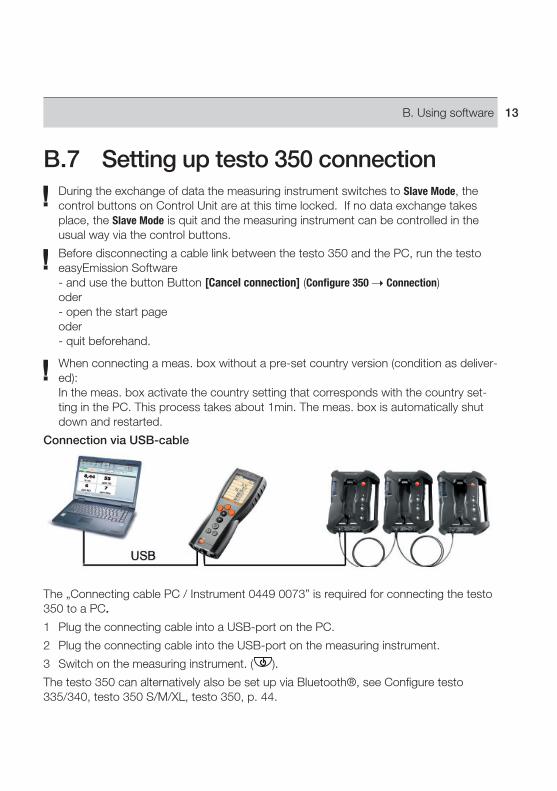
B.7 Setting up testo 350 connectionDuring the exchange of data the measuring instrument switches to Slave Mode, the control buttons on Control Unit are at this time locked. If no data exchange takes place, the Slave Mode is quit and the measuring instrument can be controlled in the usual way via the control buttons.
Before disconnecting a cable link between the testo 350 and the PC, run the testo easyEmission Software - and use the button Button [Cancel connection] (Configure 350 Connection)oder- open the start pageoder- quit beforehand.
When connecting a meas. box without a pre-set country version (condition as deliver-ed):In the meas. box activate the country setting that corresponds with the country set-ting in the PC. This process takes about 1min. The meas. box is automatically shut down and restarted.
Connection via USB-cable
The „Connecting cable PC / Instrument 0449 0073” is required for connecting the testo 350 to a PC.
1 Plug the connecting cable into a USB-port on the PC.
2 Plug the connecting cable into the USB-port on the measuring instrument.
3 Switch on the measuring instrument. ( ).
The testo 350 can alternatively also be set up via Bluetooth®, see Configure testo 335/340, testo 350 S/M/XL, testo 350, p. 44.
B. Using software 13

Connection via Bluetooth®
Both the Bluetooth®-modules on PC in the testo 350 must be activated Blue backg-round / white symbol = Bluetooth® on, Bluetooth® connection to meas. box up and running.
The connection is set up automatically via a Bluetooth® wizard. This wizard is started when the Bluetooth® interface is selected in the configuration of the testo 350, see Con-figure testo 335/340, testo 350 S/M/XL, testo 350, p. 44
Depending on the Bluetooth® module of the PC the input of a password or main key may be required for device recognition. For all Testo instruments this is: 1234.
The status of the Bluetooth® connection is indicated by the Bluetooth® symbol in the task bar (blue: connected, white: not connected).
Connection via USB data bus controller
The USB connection via data bus controller is set up directly to the meas. boxes.
Before connecting to a bus system, all analyzer units must first be equipped with the identical country version and firmware version.
Prior to commissioning a bus system, the bus address, bus rate, application and measuring location must be configured separately in each analyzer unit.
The USB data bus controller is a HighPower unit, an additional USB hub with its own power supply may be required.
C. Operation14

Operation of the CANcaseXL box and/or the VN1610 CAN interface requires installa-tion of the USB driver. (The USB driver can be found on the testo easyEmission soft-ware CD in the subdirectory \CanCaseXL\setup.exe).
1 Plug the connecting cable into the USB data bus controller (Channel 1) and into the meas. box (DATA).
2 Connect the USB data bus controller with the PC: Insert the USB plug (type B) into the USB port on the data bus controller, insert the USB plug (type A) into a USB port on the PC.
3 Connect the electric power supply to the meas. box.
4 Start the software testo 350-data bus controller under Start > Programms > Testo > testo 350 data bus controller.
5 Start the testo easyEmisson Software under Start > Programme > Testo > testo easyEmisson software and set up a connection to the testo 350.
D. Application example 15

C. Operation
Quick access toolbar: Fast access to established modulesTab Testo: Possibility of a licence extensionRibbon bar: Displays existing modules, sorted by module groups.
Open module: Select desired module, e. g. Configuration The modules can also be opened via the Quick Access Toolbar. The menus have the
same name as the corresponding module groups.Some of the modules can only be opened if data was stored or specific data was selected in advance in another module.
If a module is not activated, the homepage containing the modules required most frequently (favourites) appear enabling direct access. Some modules consist of several tabs (e.g. Configure testo 350 S/M/XL module):
Select required tab e.g. Instrument dataWork area: The work area ia the area in which all inputs are carried out.
You can switch between the standard display and full-screen display in the work area with [F11].
D. Application example16

D. Application exampleThe most important steps required for a typical application of the software is explained in this Chapter using an example.
A detailed description of all software functions can be found at Functions, p. 17.
Configuring software
1 Tab Settings Configuration.
2 Tab Own data Enter/change address data.
3 Tab Units Select units.
4 Tab Backup Make settings.
5 Taking on changes: [Apply]
Configuring the instrument
1 testo 335/340, testo 350 S/M/XL, testo 350 Configure testo 335/340 or Configure testo 350 S/M/XL, Configure testo 350
2 Print text Own address data [Ready]
Setting up new folders
1 Folder Insert new folder
2 Enter new folders in the corresponding boxes [Save]
Setting up a new location
1 Locations Insert new location
2 Enter new location in the corresponding boxes in the tabs Location, Installation, Flow data, Data sheet [Save]
Transmitting location(s) to the instrument
1 testo 335/340, testo 350 S/M/XL, testo 350 Transmit measure locations
2 Select location(s) in the Measure locations on PC folder ( ) [Transmit]
E. Functions 17

Carrying out measurements
To activate location, carry out measurement and save reading: see Instruction manual on testo 335, testo 340, testo 350 S/M/XL, testo 350.
Reading in measurement data protocol(s) from the instrument
1 testo 335/340, testo 350 S/M/XL, testo 350 Read measurement data
2 Select measurement protocol(s) in tab Measurements in instrument ( ) [Read]
Displaying and printing a measurement protocol
1 Measurements Search measurement
2 Select measurement protocol View
3 Print measurement protocol: Print
E. Functions18

E. Functions
E.1 Enhance licence
Input of a separate licence key is required for every instrument type in order to enable corresponding software functions.
1 Open Testo tab: ( )Enhance licence ( )
2 Enter licence key (located on CD packaging) [OK]
E.2 General
E.2.1 Previous module Scroll back to previous module: Previous module
E.2.2 Initial page Open initial page: Initial page
The initial page includes the modules used most frequently for direct access (favourites).
E. Functions 19

E.2.3 Exit End program: Exit
- If you have not carried out data backup on the day, the Database backup window will open offering you the following options:
· Complete backup: A complete backup is made of the database.· Save changes: Any changes made since the last backup will be saved.· Currently no backup: Program is ended without data backup being carried out. Carrying out data backup: Select required option ( ) [OK] [OK].
E.3 Folder
Folders are given the names of customers, e.g. companies. Each folder contains the locations with the relevant measurement protocols.
The Search folder, Show folder, Change folder data, Insert new folder and Import folder data modules can be opened via the Customer menu.
E.3.1 Search folderUsing the Search folder module, you can search for folders using search criteria
Opening the module
Folder Search folder
- The list of folders appears
Click on symbol .
Select desired search criterion (condition) for a field.
E. Functions20

- All folders whose entry begins with the corresponding condition, e. g. in the field Cont-act Persons, are displayed
- If several search criteria (conditions) are entered, only those customers are found for whom these critereia (conditions) apply.
Activating folders
If a folder is not activated, the Show folder and Change data folder modules cannot be opened.
Activating folders
- The selected folder is highlighted in colour.
Displaying folder data
Activating folders [Show]
- The Show folder module is opened, see Show folder , p. 20.
Changing folder data
Activating folders [Show]
- The Change data folder module is opened, see Change data folder , p. 21.
Insert new folder
[New]
- The module Insert new folder is opened, see Insert new folder, p. 21
Deleting folders
Activate folders [Delete] Yes
- The folder is deleted.
Several folders can be activated and deleted. If a folder is deleted, all measure loca-tions and measurements are also deleted.
E.3.2 Show folderThe folder data and other stored information about a folder can be displayed with the Show folder module.
Opening a module
The Show folder module can only be opened if a folder has been activated in the Search folder module, see Search folder, p. 18.
Folder Search folder
The Show folder module is divided into two areas. The Address tab is located in the upper area while the Locations tab is located in the lower area.
E. Functions 21

E.3.2.1 Address
Changing address
[Change folder]
- The Change data folder module is opened, see Change data folder, p. 21.
Deleting folders
[Delete folder] [Yes]
- The folder is deleted.
Searching for folders
[Search folder]
- The Search folder module is opened, see Search folder, p. 18.
E.3.2.2 List of locations
Activating location
If a location is not activated the Show measure location data and Change measure location data modules cannot be opened.
Activating a location
- The selected location is highlighted in colour.
Displaying measurement location data
Select location [Show]
- The Show measure location data module is opened, see Show measure location data, p. 23.
Changing measurement location data
Activating location [Change]
- The Change measure location data module is opened, see Change measure location data, p. 25.
Deleting a location
Activating location [Delete] Yes
- The location is deleted.
Setting up a new location
[New]
- The Insert new location module is opened, see Insert new location, p. 25.
E. Functions22

E.3.3 Change data folderExisting folder data can be changed with the Change folder data module.
Opening a module
The Change data folder module can only be opened if a folder was activated in the Search folder module, see Search folder, p. 18.
Folder Change data folder
Changing data
Enter changes to the folder data in the corresponding boxes [Save]
- The Show folder module is open, see Show folder, on this page.
E.3.4 Insert new folderA new folder can be set up with the Insert new folder module.
Opening the module
Folder Insert new folder
Enter new folder data in the corresponding boxes [Ready]
- The Show folder module is opened, see Show folder, on this page.
E.3.5 Import data folderUsing the Import data folder module, existing folder data can be imported from other applications.
Opening the module
Folder Import data folder
Importing data
Before importing folder data, it has to be changed to a supported import format:· Text file with separating character (comma, semicolon, Tabulator)· Microsoft Access® database· Microsoft Excel® worksheetStandard programs (such as Microsoft® Outlook®) usually support one of the named formats.
1 Select import format ( ) [Locate]
2 Select file to be imported.
When importing an Access database you may be required:
E. Functions 23

To enter User ID and Password.
3 [Next >]
When importing an Excel worksheet you may be required:
To select a worksheet [Next >].
When importing an Access database you may be required:
To enter User ID/Password.
To select a table [Next >].
Allocating import data
Once the data is read in, the data boxes have to be allocated. Only allocated data boxes will take effect.
When importing from a text file, it is possible that the first line does not include any address data. If required:
First line contains column name ( )
1 Open list box ( ) - Select target data box
- The import data box is allocated to the target data box.
2 Repeat step 1 for all required data boxes.
If the data field Folder exists, but the file description has already been allocated in the software, then the existing data are replaced by the imported data.
If the data field Folder is empty, then the corresponding dataset is not imported.
3 [Apply] [OK]
- The Search folder module is opened, see Search folder, p. 18..
E. Functions24

E.4 Locations
The Show measure location data, Change measure location data, Insert new location modules can be opened via the Locations function.
E.4.1 Show measure location dataSystem data and the measurement data saved in a system can be displayed with the Show measure location data module.
Opening a module
Locations Show measure location data
The Show measure location data module is divided into two areas. The Location, Owner file, Installation and Flow data tabs are located in the upper area while the Measurement values tab is located in the lower area.
E.4.1.1 Location, Owner file, Installation, Flow dataInformation on the measurement location is displayed.
Details folder
[Details folder]
- The module Details folder is opened, see Details folder, p. 20
Data sheet
[Data sheet]
- The module Data sheet is opened.
The module Data sheet can only be opened when the module Use data sheet (Settings - Configuration - Programme) is activated.
The displayed system data are determined in the Data sheet designer. (Settings - Data sheet designer), see p. 49
The data which are displayed for displayed archiving are determined in the data.
Enter input in the editable fields and confime with [Save].
E. Functions 25

Change measure location data
[Change]
- The module Change measure location data is opened, see Change measure location data, p. 25
E.4.1.2 Measurements
Activate measurement protocol
If a meaurement protocol is not activated, the Display measurement data module cannot be opened.
Activate the measurement protocol
- The selected measurement protocol is highlighted with colour.
Displaying a measurement protocol
Activating the measurement protocol [Display measurement]
- The Display measurement data module is opened, see Display measurement data, p. 27.
Deleting a measurement protocol
Activate the measurement protocol [Delete] [Yes]
- The measurement protocol is deleted.
Merging measurement protocols
Multiple measurement protocols can be merged into one measurement protocol.
1 Activate measurement protocols, for multiple selections, hold the [Strg] key depres-sed.
2 [Connect]
- The measurement protocols are merged into one protocol.
E. Functions26

E.4.2 Change measure locations data Existing location data can be changed using the Change measure location data module.
Opening the module
Locations Change measure location data
Changing data
Enter changes to the location in the appropriate boxes [Save]
- The Show measure location data module is opened, see Show measure location data, p. 23.
E.4.3 Insert new locationA new location can be set up with the Insert new location module.
Opening the module
Locations Insert new location
Enter the data from the new location in the corresponding boxes in the location, Instal-lation, Flow data, Data sheet tabs [Save]
- The Show measure location data module is opened, see Show measure location data, p. 23.
Installation tab
If a required fuel is not shown in the selection list, it can be added to the list manually or overwritten. Make sure that the fuel that has been manually added has the exact same name in the measuring instrument.
If a measuring location needs to be transferred to the measuring instrument, the fuel must have exactly the same name as the one stored in the measuring instrument.
E. Functions 27

E.5 Measurements
The Search measurement and Display measurement data modules can be opened via the Measurements function.
E.5.1 Search measurementYou can search for measurement protocols stored in your PC using the Search measure-ment module.
Opening the module
Measurements Search measurement
- All of the measurement protocols stored in the PC are displayed. To display the mea-surement protocols from only one location, see Show measure location data, p. 23.
Activate a measurement protocol
If a measurement protocol is not activated, the Display measurement data module is not opened.
Activate measurement protocol
- The measurement protocol is highlighted by a colour.
Display a measurement protocol
Activate measurement protocol [View]
- The Display measurement data module is opened, see display measurement data, p. 27.
Delete a measurement protocol
Activate a measurement protocol ( ) [Delete] [Yes]
- The measurement protocol is deleted.
Changing the location
Activate measurement protocol [Change location] Activate location [OK]
- The measurement protocol is assigned to the selected location.
E. Functions28

Connect measurement protocols
Multiple measurement protocols can be merged into one measurement protocol.
1 Activate measurement protocols, for multiple selections, hold down the [Ctrl] key.
2 [Connect]
3 Select location where the measurement protocol is to be saved [OK]
- The measurement protocols are merged into one protocol.
Exporting/importing a measurement protocol
Export only: Activate measurement protocol
[Export] or [Import] Enter File name ( ) [Save]
- The measurement protocol is exported/imported.
The following registers are available as information in the Excel file :Register testo: Measurement resultsRegister Information: Incl. start and end time of a measurementRegister Folder: Name and customer numberRegister Measurement location: Incl. address, measurement location description
E.5.2 Display measurement dataMeasurement protocols can be displayed and processed via the Display measurement data module.
The Display measurement data module can only be opened if a measurement protocol was selected in the Search measurement or Show measure location data modules, see Search measurement, p. 26 or Show measure location data, p. 23.
Open a module
Measurements Display measurement data
E.5.2.1 InformationInformation on the measurement protocol is shown in the Information tab
Enter text in the Remark box.
Print measurement protocol
Print measurement protocol with information data and readings: [Print report]
Select form template [OK] Set printer [OK]- Print report
E. Functions 29

Display print preview
Display measurement protocol as a print preview: [Preview report]
Save measurement protocol in PDF format
[Save as PDF]
E.5.2.2 GraphicsThe readings are shown in graphics form in the Graphics tab (maximum 16 channels).
Print measurement protocol
Print measurement protocol with information data and readings: [Print report]
Select form template [OK] Set printer [OK]- Print report
Display print preview
Display measurement protocol as a print preview: [Preview report]
Select form template [OK]- A report will be created.
Save measurement protocol in PDF format
Save as PDF format
[Save as PDF]
[Save as PDF] Enter file name ( ) Select file type ( ) [Save]
Print measurement protocol as graphic
[Print bitmap]
Printer settings [OK]
Save measurement protocol as graphic
[Save bitmap][Save as PDF] Enter file name ( ) Select file type ( ) [Save].
Changing features in graphics
1 [Settings]
2 Channel: Select measurement channels ( ), Legend: Enter channel name.
3 Save settings: [OK]
E. Functions30

E.5.2.3 Measure valuesThe readings in a table or list are shown in the Measure values tab.
Diluted measurement values from online measurement are shown in italics.
Print measurement protocol
Print measurement protocol with information data and readings: [Print report]
Select form template (Template form, see Chapter G. Appendix) [OK] Set printer [OK]- Print report
Display print preview
Display measurement protocol as a print preview: [Preview report]
Select form template (Template form, see Chapter G. Appendix) [OK]- A report will be created.
Save measurement protocol in PDF format
[Save as PDF] Enter file name ( ) Select file type ( ) [Save]
Export readings as an Excel file
[Export Excel] Enter File name ( ) [Save]
- The measurement protocol will be exported
The following registers are available as information in the Excel file :Register testo: Measurement resultsRegister Information: Incl. start and end time of a measurementRegister Folder: Name and customer numberRegister Measurement location: Incl. address, measurement location description
Export readings into the PC’s clipboard
[Clipboard]
- The readings are exported as a file text, separated by tabs, into the PC’s clipboard.
Analysis of measurement results
The mean, maximum and minimum readings can be displayed. The analysis range can be limited.
[Min/Max/Mean] Activate desired functions ( ) [OK]
Option:
Mark reading range Open context menu Choose a designation for the analy-sis range (Range 1, 2, or 3).
E. Functions 31

E.5.2.4 Data sheetThe tab data sheet shows system data.
Open Data sheet tab: Data sheet
Tab Data sheet can only be opened when the module Use data sheet (Settings - Configu-ration - Programme) is activated.
The data which are displayed for archiving are determined in the data sheet designer (Settings - Data sheet designer), see p. 49
Scroll through pages
[Next page / Previous page]
Alter view
[Zoom in / Zoom out]
Save data sheet as PDF
[Save as PDF]
[Save as PDF] Enter file name ( ) Select file type ( ) [Save]
Print data sheet
Print data sheet with information data and measurement values: [Print report] Set printer [OK]
- Print protocol
Save data sheet
Confirm input with [Save].
E. Functions32

E.6 Measure types
E.6.1 Manage measure typesMeasure types serve to repeatedly carry out measurements in a predefined way. Mea-surement programs (logger programs), formulae to calculate additional values (formula editor) and the layout for printing measurement data (form designer) can be stored in a measure type.
Opening a module
Measure types Manage measure types
The Manage measure types module is divided into two sections. The Measure types tab is located in the upper section, the Logger programme, Input fields, Formula builder, Ranges of measure value and Report designer tabs are located in the lower section.
Activating a measure type
Activate measure type
- The measure type selected is highlighted in colour.
- The most important information stored with the respective measure type is shown in the Logger programme (only with user-defined measure types), Formula builder and Report designer tabs. Formulae can be stored in the Input fields folder (see also Help key) so that the values are calculated from the values in the other fields. Value ranges are specified in the Ranges of measure value tab. The start of a range is given as Range 1. The scope of the value range is entered into Number of rows.
Option:
Open logger program / formula editor /form designer tab: [Edit]
Setting up user-defined measure type
Ensure you enter the correct measure type name, it cannot be changed later.
[New] Input name [OK]
E. Functions 33

Deleting a user-defined measure type
Only user-defined measure types (User) can be deleted. Select user-defined measure type (on name) [Delete]
Exporting a user-defined measure type
Only user-defined measure types (User) can be exported.
1 Select user-defined measure type (on name) [Export ]
2 Enter storage location and file name [Save]
Importing user-defined measure type
It is not possible to overwrite/replace existing measure types.
[Import ] Select a user-defined measure type (zip file) (on name) [Open]
E.6.2 Define logger programmeLogger programmes can only be defined for user-defined measure types (User), this is not possible for measure types (System) set up in the system.
The Define logger programme module can only be opened if a measure type was user difined in the Manage measure types module, see Manage measure types, p. 31 The logger programme is always allocated to the activated measure type.
Opening the module
Measure types Define logger programme
Defining a logger programme
A logger programme of type testo 335/340 (measurement program), testo 350 S/M/XL (measurement program) , testo 350 (measurement program) and Online (testo 350 S/M/XL / testo 350) (online measurement program) can be defined respectively for each user-de-fined measure type.
1 Activate tab with the required logger programme type.
2 Enter characteristics of logger programme [Ready]
Only for Online testo 350
Individual measurement and flushing phases can be defined in an Online testo 350 loggerprogram.
E. Functions34

Enter measure rate
Measure rate ( )
- The data recording of measure rates can be started. If a measure rate of 0 is set, no measurement value will be stored
Condition 1 (max duration)
Max duration ( )
- the duration of each phase is set
Condition 2 (max number)
Max number ( )
- the number of measurement values of each phase is entered
Condition 3 (overshoot/shortfall of a measurement value)
Condition ( )
- the measurement phase is ended in case of oversoot/shortfall of a value in a measurement channel.
Set repitition loops
Repeat measurement phases ( )
When setting the measurement and flushing phase, the measurement and flushing cycles should be adhered to (see instruction manual for instrument).
E.6.3 Formula builder The Formula builder module can only be opened if a measure type has been selected in the Measure types module, see Manage measure types, p. 31. The formulae are always allocated to the activated measure type.
Opening module
Measure types Formula builder
Adding/editing formulae
A separate measurement channel (column) is set up for each formula and is identified by a freely selectable measurement channel name.
1 Adding a formula: Add new column ( ) Enter measurement channel name [Next >]
-or-
Editing a formula: Change already defined additional column ( ) Select measurement channel name [Next >]
E. Functions 35

The naming of standard columns (measurement channels) stored in the system, con-sists of the elements “measurement unit” and “measurement parameter”. If several flue gas analyzers are connected in a bus-system, the “bus-address” of the instru-ment is additionally given in order to clearly identify the individual measurement chan-nels. For this reason, to create formulae for bus-systems, use only columns (measu-rement channels), which have been calculated from an existing measurement (Get columns from an existing measurement), as these already have the respective bus-ad-dress in their name. This guarantees that the columns used in the formulae are clearly allocated to respective measurement channels in the instruments, and thus also gua-ratees the applicability of the formulae.
2 Using standard columns (standard measurement channels) stored in the system: Use standard columns ( ) [Next >]
-or-
Using columns (measurement channels) from an already existing measurement: Get columns from an existing measurement ( ) Select measurement [Next >].
3 Enter a calculation formula for the column: Select columns ( Double-click) and link by mathematical operators (+, -, *, /). Press the [Help] button for a detailed description of the syntax of the formulae.
4 Check the formula you have entered for validity: [Check].
5 Save the formula: [Save]
E.6.4 Report design The Report designer module can only be opened if a measure type has been selected in the Manage measure types module, see Manage measure types, p. 31. The form is always allocated to the measure type activated.
A print form must be defined in order to be able to print records of a measure type.
Opening the module
1 Measure types Report design
The form designer module is separated into two areas. The Field, Font, Border and Page tabs are located in the left area while the Editor and Preview tabs are located in the right area.
E. Functions36

Setting up/editing a form
The elements and features of the form can be set up or edited using the functions in the Field, Font, Border and Page tabs, see Field, Font, Border, Page, p. 36.
Please proceed as follows:
· Only placeholders for data and readings are shown in the Editor and Preview tabs and on the printout of a form within the form designer. The form boxes are only filled with data and readings when the respective measurement is printed.
· The following steps are required for entering readings, acquired using the analysis function, in the form (see Measure values, p. 29, Analysis section):
1 Carry out sample measurement for measure type.
2 Select the Reporting button in the Display measurement data module, Measure values tab and activate the required functions. Optional: If the analysis functions are to be applied to certain ranges, define the required ranges, for example, in the readings table (Range 1 to 3) (via context menu: ).
3 Print measurement using [Print] [OK] (a white sheet will be printed if form boxes have not been set up).
- The analysis functions are allocated to the measure type during printing and are available as data boxes in the ditor.
Save form
The saved form is used to print records of the measure type activated.
[Save]
Save form as template
Stored forms can be used as a template for additional forms and to restore to original states if modified by mistake (backup copy).
[Backup as ...] Enter Form name [OK]
Restore form
Restored forms can be used as a template for other forms and to restore to original sta-tes if modified by mistake (backup copy).
[Restore form ...] Select form name [OK]
Delete form template
[Restore form ...] Select form name [ Del ] (Keypad).
Print form
[Print]
- The form is printed as it is shown in the Preview folder.
E. Functions 37

E.6.4.1 Field, Font, Border, PageThe box properties of the form boxes (field type, font and margin) and the page proper-ties can be changed in the tabs.
The displayed properties for box, font and margin are valid for the form box which is selected in the Editor tab (in the same module).
Set up box type
Select box type in Field ( ):· Textfield: Text is entered in the form box.
Enter text in the text box.· Data field: The selected data box value stored in the database (reading, folder or sys-
tem data) is entered in the form box. Select data box ( ).
· Graphics (Logo): The selected graphic is entered in the form box. Select graphic: [File ...] Select file [Open]
· Chart (measured data): The measurement protocol readings stored in the database are input as diagram.
· Table: The measurement protocol readings stored in the database are input in form in the form box.
By marking the printing area, you can determine which area of the table will be prin-ted.
Select printing area ( ): Limit printing area or print out entire table Select range of table to be printed ( ): Select individual areas or print out entire table Select data of table to be printed ( ): Select the data to be printed
Determining the font
This function is only available if the Textfield or Data field box type is selected.
Select font in Font ( ):· Standard font: The standard font set in the Page folder is used.· Special font: A font deviating from the standard font is used.
Select font: [Font ...] Set values [OK]· Barcode: The “Barcode” font is used.
Select alignment in the Alignment text box ( ).
Border settings
Select border properties for the form box in Border ( ).
Page settings
E. Functioins38
Page properties and the form standard font can be changed in the Page folder.
Input and set page properties ( ).
Define standard font: [Default font ...] Adjust values [OK]
E.6.4.2 EditorForm boxes can be inserted, modified in size and deleted in the Editor tab.
Insert new form box
Select corner point of form box on a free area of the form (keep pressed) Drag form box until it is the right size End input, release
Move form box
Select form box (and then keep pressed) Move form box to required position End moving, release.
Delete form box
Highlight form box [ Del ] (keypad).
E. Functioins 39

E.7 testo 335/340, testo 338, testo 350 S/M/XL, testo 350
Only the testo 338: with the testo 338, only saved measurement protocols can be transferred to the PC, see section 7.3 Read measure data.
E.7.1 Transmit measure locationsLocations can be transmitted to a Control Unit testo 350 S/M/XL / testo 350 or a testo 335, testo 340 using the Transmit measure locations module.
testo 350 S/M/XL: only: If there is no Control Unit in the system (Connection via USB Databus-Controller) this function is not available.
Opening the module
testo 335/340, testo 350 S/M/XL, testo 350 / / Transmit measure locations
The Transmit measure locations module is divided into two areas. The Measure locations on PC tab is located in the upper area while the Measure locations on instrument tab is located in the lower area.
E.7.1.1 Measure locations on PCThe Measure locations on PC tab shows the locations saved on the PC.
E. Functions40

Search for a specific location
Enter search criterion in a search box Start search: [Search]
Transmit location(s) to measuring instrument
Options:
Select all locations: [Select all]
Cancel location selection: [Select none]
Select location(s) ( ) [Transmit]
Display location
Activate location [Display]
- The Show measure location data module is opened, see Show measure location data, p. 23.
Change location
Activate location [Changes]
- The Change measure location data module is opened, see Change measure location data, p. 25.
E.7.1.2 Measure locations on instrumentThe Measure locations on instrument tab shows the locations which are saved in the inst-rument.
Select location(s)
Select location(s) ( ) [Delete]
The selected locations are deleted together with the associated measurement data.
Activating location(s)
Select location ( ) [Activate]
The activated location is filled up with measurement data from the instrument.
Options:
Select all location(s): [Select all]
Cancel location selection: [Select none]
E. Functions 41

E.7.2 Transmit logger programmes
Opening a module
testo 350, testo 335/340 ( ) / Transmit logger programmes ( ).
The Transmit logger programmes module is divided into two sections. The logger program-mes on PC tab is located in the upper section while the logger programmes on instrument, tab is located in the bottom section.
Transmit logger programmes to measuring instrument
There are always 6 programs saved on every measuring instrument. If a programme is transmitted to a measuring instrument, an existing programme is always overwritten. A programme can be transmitted simultaneously to several instruments in instruments of type testo 350.
The programme names are accepted in testo 335, testo 340 and testo 350, while in testo 350 S/M/XL the standard names available are shown in the instrument.
1 Select logger programmes on instrument which is/are to be overwritten.
2 Select logger programmes on PC which is to be overwritten [Transmit]
Activating logger programmes on instrument
Only 1 measurement programme per instrument can be activated.
Select logger programmes on instrument ( ) [Activate])
E.7.3 Download measurement data Measurement protocols stored in measurement instruments can be transmitted to your PC using the Download measurement data module.
Open module
testo 335/340, testo 338, testo 350 S/M/XL, testo 350 / / / Download measu-rement data ( ).
Measurements in instrument
Options:
Select all measurements in instrument: [Select all]
Cancel selection of measurements in instrument: [Select none]
Ensure correct selection of the measure type to which the measurement(s) are alloca-ted; this regulates allocation to formulae. Your selection cannot be changed at a later stage. Allocation to a measure type is automatic in instruments of type testo 335, testo 340 using measurement program name(s).
E. Function42

1 Only testo 350: Select Measure type ( ).
2 Select measurements in instrument:( ) [Read]
- The measurement protocol is saved on your PC at the same location as in the inst-rument. If the location of the selected measurement protocol is not available on your PC, you will be asked if it should be set up.
-or-
2 Select measurements in instrument: ( ) [Donwload as ...] Select target locati-on [OK]
Delete measurements in instrument
Activate measurements in instrument [Delete] [Yes ]
- The measurement is deleted.
Display measurements in instrument
If the selected location was not saved on the PC, this function is not available.
Select measurements in instrument: ( ) [View]
- The Display measurement data module is opened, see Display measurement data, p. 27.
If the incorrect interface was inadvertently selected when installing the software, the message No connection to the testo 350/testo335 system found appears.
Configure testo 335/340, testo 350 S/M/XL, testo 350 Select interface ( )
E.7.4 Online measurementUsing the Online measurement module, up to 9 flue gas measurements can be carried out simultaneously; instrument control is via PC. Readings are transmitted directly to your PC and and then shown.
Flue gas analyzers testo 350 S/M/XL and flue gas analyzers testo 350 cannot be used together for parallel online measurements.
testo 350 S/M/XL und testo 350: only: When carrying out a measurement with several flue gas analysers, instrument groups can be set up which can be controlled by the soft-ware like a separate instrument, see Manage instrument groups, p. 48.
testo 350 S/M/XL und testo 350: only: If a flue gas analyser is configured in several instrument groups, there may be reciprocal influencing of the program if online measure-ments are running simultaneously (e.g. rinse phases may apply to flue gas analysers, not to instrument groups).
E. Function 43

Opening the module
testo 335/340, testo 350 S/M/XL, testo 350 / / Online measurement
- The folder with Online measurement number 1 is opened.
Options:
Set up new Online measurement folder: +
Display other Online measurement (on folder number).
Carry out Online measurementOnly parameters and measurement units are shown which are activated in the Display order tab (in the same module).
The smallest possible measurement cycle depends on the type of connection and number of instruments which have to be read out from the software: · testo 335, testo 340: 1 sec.· testo 350 S/M/XL, serial connection: 5s, 5s for each additional flue gas analyser· testo 350 S/M/XL, USB connection: 1s per flue gas analyser· testo 350: 1sIf the measurement cycle is set to 0 sec., the readings in the Display tabare conti-nuously updated but not saved.
1 Select Measure type to which the measurement is to be allocated ( )
2 Set Measurement cycle ( )
testo 350 S/M/XL und testo 350: only:
3 Select instrument group from which readings are to be read ( )
4 When selecting a user-specific measuring process: in order to be able to use an online logger program, remove the checkmark next to Real time logger program deactivated ( ).
5 Start measurement: [Start] or [Start all sessions]
- Online measurement starts (initialisation phase may possibly run first)
- Readings are displayed as table (Measure values tab), display boxes (Display folder) or graphic (Chart tab), see Measure values, Display, Chart, on this page.
6 End measurement: [Stop] oder [Stopp all sessions]
E.7.4.1 Measure values, Display, Chart· Measure values tab: Table with all measurement channels and data/time of single
measurements. Save readings in Online location: [Save as...]
Export readings to Microsoft Excel (Microsoft Excel 2000 or newer required!): [Export Excel]
E. Functions44

Export readings to clipboard (text file separated by tab stop): [Clipboard]· Display tab: Display fields with all measurement channels.
Save readings manually (only available if measurement cycle is set at 0s): [Save]
Alter size of display windows: Drag slide control ( ).
During a measurement, Mean values, Max values, Min values can be displayed instead of the actual values: [Actual values] ( )
Show large display boxes: [extra large] ( )
Display measurement values in separate window which is always on top: show mini window ( ).
· Chart folder: Measurement diagram with four selectable measurement channels and automatic scaling of the time axis.
Adjust diagram characteristics (displayed channels, line colour, scale): [Settings]
Save diagram as bitmap file: [Save bitmap]
[Save bitmap] Enter file name ( ) Select file type ( [Save]
E.7.4.2 Display orderThe measurement channels available are shown in the All channels area. Only the para-meters and measuring units are available which are in the current display sequence of the measuring instrument
The measurement channels, which appear on your PC during online measurement, are shown in the Shown channels area.
Setting up the display sequence
Add/delete measurement channels: [Add ->], [Add all ->], [<- Delete] or [<- Delete all]
Arrange order of measurement channels: Select measurement channel [Up] or [Down]
If necessary enter the value for the alarm limit: Exceed lower limit ( ), Exceed upper limit ( )
E.7.4.3 Instrument control
testo 350 S/M/XL, testo 350
Some functions for instruments of type testo 350 S/M/XL, testo 350 can be adjusted.
Select instruments which are to be adjusted: select instrument(s) ( ), [Select all] or [Select none]. When analysis boxes are selected, [Meas. type] und [Dilution] are activa-ted.The functions apply to measuring instruments but not instrument groups.
E. Functions 45

Start flue gas measurement:[Flue gas measurement]
Start fresh air phase (only in instruments with fresh air valve option): [Fresh air]
Start zeroing: [Zeroing]
Set dilution factor (only in instruments with fresh air valve or measurement extension CO option) (CO: testo 350 S/M/XL; for single slot: testo 350)): [Dilution...] Set factor (1 = dilution off, 2 to 40 and automatic = CO dilution; all sensors = dilution on everything) [OK]
Start differential pressure measurement: Difference Pressure. Values are internally sto-red and added to the table.
Start fine draught: [Fne draught]
testo 335, testo 340, testo 350
Flow velocity and differential pressure can be selected in addition to flue gas measure-ment.
Start flue gas measurement: Fluegas measurement ( ) [Start]
Start flue gas measurement + m/s: Fluegas measurement + m/s ( ) [Start]
Start flue gas measurement + p: Fluegas measurement + p ( ) [Start]
For flow velocity/differential pressure measurements: Before a measurement, carry out the measurement location settings (Pitot tube factor and correction factor). Do not measure for longer than 5 mins, as pressure sensor drift can lead to measure-ment values outside the tolerance limits.
E.7.5 Configure testo 335/340, testo 350 S/M/XL, testo 350
Open a module
testo 335/340, testo 350 S/M/XL, testo 350 testo 335/340 konfigurieren, testo 350 S/M/XL konfigurieren, testo 350 konfigurieren
Select connection type
Select flue gas analyzer and type of connection:
Connection type Bluetooth®
If the connection type Bluetooth has already been selected, the Bluetooth assistant starts automatically. In order to be able to select a different connection type, cancel the assitant or deactivate the Bluetooth module of the PC before starting the easyEmission software.
- Bluetooth assistent starts automatically all Bluetooth instruments in the sur-rounding area are searched
E. Functions46

Select the desired Testo measuring instrument (testo 335, testo 340, testo 350 S/M/XL, testo 350) connection is set up.
If the required instrument is not found, the search procedure must be repeated.
Only testo 350 with connection via RS232: Select Port used ( ).
Connection type CANcaseXL box and/or VN1610 CAN interface
Switching between the USB data bus controllers by selecting the connection type is not possible with standard user rights on Windows® Vista or later. To activate the other
USB data bus controller, exit the easyEmission software and run it again with admi-nistrator rights (Start > Programs > testo > testo easyEmisson Software > easyEmisson.exe > right mouse key > Execute as administrator). Once the selection has been made,
exit administrator mode and restart the easyEmission software.
E.7.5.1 Measuring instruments (testo 350S/M/XL, testo 350only)
The instruments connected are displayed. In this way, the configuration settings of all system components can be quickly called up and changed in a bus system (only with Control Unit testo 350 XL and testo 350).
Select instrument whose Configure data is to be displayed/modified.
[[Switch off analyzer]: If no logger program is active, pressing [Switch off analyzer] shuts down all connected analyzer units and the control unit.
If a logger program is running on the selected instrument, [Switch off analyzer] is hidden
E. Functions 47

E.7.5.2 Show configuration data / Change configuration Select tab
- The Configure data available is shown in separate tabs whose name corresponds to the function name in the menu of the measuring instrument.
In some tabs modifications can be made to the configure. The modification options cor-respond as far as possible to those in the measuring instrument menu, see Instruction manual for measuring instrument.
Sensors
The sensors of the instrument can be calibrated and adjusted. On the testo 350 the mea-suring accuracy for sensors showing cross-sensitivity to other gases, can additionally be optimized. This is accomplished via cross-sensitivity adjustments (only possible with the testo easyEnmission software)..
Notes on the operation sequence calibration / adjustment / cross-sensitivity adjustment:
1 Select the sensor to be calibrated / adjusted (left hand selection bar) [Calibrati-on / Adjustment].
If password protection is activated: Enter the password [Next].
2 Select the desired function ( ).
3 Enter the test gas concentration (nominal value) [Next].
4 Apply test gas to the gas inlet of the meas. box[Next].
5 If the indicated measurement value (actual value) is stable: [Cancel].(perform calibration only, no adjustment) -oder- [Apply] (Adjustment).
Notes on optimization of measuring accuracy (only testo 350):
For the following sensors there is a cross-sensitivity to other gases:Sensor Cross-sensitivity to
NO NO2CxHy COH2S CO, NO, NO2, SO2NO2 H2SSO2 NO2, CO
In SO2 measurement NO concentrations >1000 ppm and simultaneous O2 concent-rations >5 % in the measuring gas lead to a reduced measuring accuracy. This can-not be influenced by adjusting the cross-sensitivity.
Recommendations for optimizing the measuring accuracy of a sensor:
E. Functions48

Only optimize the measuring accuracy when the measuring instrument is equipped with the sensors to which the sensor to be optimized has a cross-sensitivity.
1 Adjust the sensors to which the optimized sensor has a cross-sensitivity.
The test gas should have a concentration which corresponds with the expected con-centration in the measuring gas.
2 Adjust the cross-sensitivity of the sensor to be optimized to all gases, to whi ch the sensor has a cross-sensitivity.
The test gas should have a concentration which corresponds with the expected con-centration in the measuring gas.
3 Adjust the cross-sensitivity of the sensor to be optimized to all gases, to which the sensor has a cross-sensitivity. The test gases should have the following properties:Optimization Cross-sensitivity- Test gas propertiesvof sensor adjustment to
NO NO2 Test gas concentration at the level of the expected NO2 concentration in the measuring gas; if unknown: approx. 80…100ppm NO2; rest: synthetic air, no NO or O2 components.
CxHy CO Test gas concentration at the level of the expected CO concentration in the measuring gas; if unknown: ca. 500…2000ppm CO; rest: synthetic air
H2S CO Test gas concentration at the level of the expected CO concentration in the measuring gas; if unknown: approx. 100…300ppm CO; rest: synthetic air
H2S NO Test gas concentration at the level of the expected NO concentration in the measuring gas; if unknown: approx. 100…300ppm NO; rest: synthetic air
H2S NO2 Test gas concentration at the level of the expected NO2 concentration in the measuring gas; if unknown: approx. 80…100ppm NO2; rest: synthetic air, no NO or O2 components.
H2S SO2 Test gas concentration at the level of the expected SO2 concentration in the measuring gas; if unknown: approx. 100…300ppm SO2; rest: synthetic air
NO2 H2S Test gas concentration at the level of the expected H2S concentration in the measuring gas; if unknown: approx. 100…300ppm H2S; rest: synthetic air
SO2 NO2 Test gas concentration at the level of the expected NO2 concentration in the measuring gas; if unknown: approx. 120ppm NO2; rest: synthetic air, no NO or O2 components
SO2 CO Test gas concentration at the level of the expected CO concentration in the measuring gas; if unknown: ca. 80…1000ppm NO2; rest: synthetic air
E. Functions 49

E.7.6 Manage instrument groups (only testo 350 S/M/XL
and testo 350)
Several flue gas analysers can be pooled to form an instrument group for online mea-surements. Each instrument or individual measurement channels in the instrument can then be allocated to several instrument groups.
Opening a module
testo 350 S/M/XL, testo 350 Manage instrument groups
The Manage instrument groups module is divided into two sections. The Available instrument groups tab is located in the upper section while the Configure instrument group tab is loca-ted in the lower section.
Setting up instrument group
Ensure that the instrument group name is entered correctly. It cannot be changed at a later stage.
[New] Enter name [OK]
Deleting instrument group
Select instrument group (on name) [Delete]
Editing instrument group
1 Select instrument group (on name).
- The instrument group selected is highlighted in colour. The configuration of the instru-ment group is shown.
2 Activate measurement channels of all instruments or certain instruments ( ) or deac-tivate ( ).
3 Save modified configuration: [Save].
E. Functions50

E.8 Settings
E.8.1 Data sheet designer The module Data sheet can only be opened when the menu Use data sheet (Settings - Configuration - Programme) is activated. The formulae are always allocated to the acti-vated measure type.
Opening module
Settings Data sheet designer
The Data sheet designer module is separated into two areas. The Field, Font, Border and Page tabs are located in the left area while the Editor and Preview tabs are located in the right area.
Create/process data sheet
The elements and features of the form can be set up or edited using the functions in the Field, Font, Border and Page tabs.
Save data sheet
The saved form is used to print records of the measure type activated.
[Save]
Save data sheet as template
Stored forms can be used as a template for additional forms and to restore to original states (backup copy).
[Backup as ...] Enter data sheet name [OK]
Restore data sheet
Restored data sheets can be used as a template for other data sheets and to restore to original states (backup copy).
[Restore data sheet ...] Select data sheet name [OK]
Print data sheet
[Print]
- The data sheet is printed as it is shown in the Preview folder.
E. Functions 51

E.8.1.1 Field, Font, Border, PageThe box properties of the form boxes (field type, font and margin) and the page proper-ties can be changed in the tabs.
The displayed properties for box, font and margin are valid for the data sheet box which is selected in the Editor tab (in the same module).
Set up box type
Select box type in Field ( ):· Textfield: Text is entered in the form box.
Enter text in the text box.· Graphics: The selected graphic is entered in the form box.
Select graphic: [File ...] Select file [Open]· Logo: The logo stored under Settings - Configuration - Own data is inserted.
Enter Logo into the text or input fiield.· Chart (measured data): The measurement protocol readings stored in the database
are input as diagram. Enter parameter.
· Entry field: Establishe input fields with conditions. Enter conditions.· Check box: Create checkbox.with conditions. Enter conditions.· Button: Create button with description. Enter description.
Determining the font
This function is only available if the Textfield, Entry field or Check box type is selected.
Select font in Font ( )· Standard font: The standard font set in the Page folder is used.· Special font: A font deviating from the standard font is used.
Select font: [Font ...] Set values [OK]· Barcode: The “Barcode” font is used.
Select alignment in the Alignment text box ( ).
Border settings
Select border properties for the form box in Border ( ).
Page settings
Page properties and the form standard font can be changed in the Page tab.
Input and set page properties ( )
E. Functions52

Define standard font: [Default font ...] Adjust values [OK]
E.8.1.2 EditorForm boxes can be inserted, modified in size and deleted in the Editor tab.
Insert new form box
Select corner point of form box on a free area of the form keep pressed) Drag form box until it is the right size End input, release
Move form box
Select form box (and then keep pressed) Move form box to required position End moving, release.
Delete form box
Highlight form box [ Del ] (keypad).
E.8.1.3 PreviewA preview of the form is shown in the Preview tab.
E.8.2 Configuration
Opening the module
Settings ( ) Configuration ( ).
E.8.2.1 InstrumentsThe instruments which are to be supported by the software can be selected in the Inst-ruments tab.
Activate required instruments ( ).
E.8.2.2 Initial pageThe modules that are to be displayed on the initial page can be selected in the Initial page tab.
Adding or removing a module
Initial page Mark module [Add] or [Delete]
Standard module (Factory setting)
Initial page [Default]
E. Functions 53

E.8.2.3 UnitsThe units for temperature, length and pressure are defined in the Units tab.
Units Select unit ( ) [Save].
E.8.2.4 Special location dataThe Special location data tab offers the option of creating additional fields for designating a location. The defined information fields are added in the Installation folder in the Change measure location data module.
1 Special location data Enter a field designation.
Option:
Create a selection list with preset values for the field.
2 [Save]
E.8.2.5 ProgrammeThe user-specific programme settings can be made in the Programme tab.
Use data sheet
Data on a system can be displayed as a data sheet
Use data sheet ( ).
Show measurement data during the fresh air phase of testo 350
During the fresh air phase, data are displayed not only with “---”
Show measure value during fresh air phase of testo 350 ( ).
E.8.2.6 Own dataYour own address data can be input in the Own data folder.
Own data Enter/change address data.
E.8.2.7 Color schemeThe monitor presentation can be selected in the tab Colour scheme.
Select desired monitor presentation ( ).
E.8.2.8 Software updateIn the tab Software, the regular automatic software check can be activated.
Check automatically for software updates
An internet connection is required for the regular check.
E. Functions54

E.8.2.9 LanguageThe country specific language can be selected in the tab Language.
Use language selected in the regional settings of the operating system: ( )
Use selected language: ( )
E.8.2.10 BackupPresettings for data backups are made in the Backup tab.
To protect your data from a fault in the hard disk, your backup files should be saved on another data carrier.
Select directory for backup files
[Search] Select directory [OK]
Determine backup methods
Full backup ( ) Select Storage interval
Changes backup ( ) Select Storage interval
E.8.3 InformationThe Information module contains 4 folders in which important information for the PC used and for the software is shown. This information is important if you contact our hotline and will help us to diagnose the fault.
Open a module
Settings Information
F. Questions and answers 55

56
E.9 Database
E.9.1 Full backup1 Full backup of data: Database Full backup
2 Confirm Information 3010: [OK]
E.9.2 Incremental backup1 Save changes since last data backup: Database Incremental backup
2 Confirm Information 3009: [OK]
E.9.3 Restore database1 Database Restore database
2 Restore data: Select time for restore [OK]
3 Confirm Information 3013: [OK]
E.9.4 Repair and compactFaults in the database occurring after a system crash or power failure can be corrected.
Repair faults in database: Database Repair and compact
E. Functions
57
F. Questions and answersQuestion Possible reasons Answer
Uninstall software. - Use Windows uninstall routine.Failure in setting up - System related problems Setting up the Bluetooth® the Bluetooth® connection connection manually,using the Bluetooth® wizard see below: Manual setup of a Bluetooth® connection
Manual setup of a Bluetooth® connection
The handling steps required to do this vary depending on which PC Bluetooth® module and operating system are used. Typically, the input template / installation assistant are called up via:
· The Bluetooth® symbol in the task bar: Bluetooth® symbol
· Windows XP: Start symbols > Programs > Program group „Bluetooth“ or similar
· Windows Vista: Start symbols > System control > Hardware and sound > Bluetooth
· The password or the pass key for the instrument identification for all testo instru-ments is: 1234
If necessary, also refer to the documentation of your Bluetooth® module or operating system.
If your query was not included, please contact your nearest distributor or Testo’s Custo-mer Service. You will find contact details in Internet at www.testo.com.
F. Questions and answers

G. AppendixTemplate form flue gas measurement
G. Appendix58

Template form online measurement
G. Appendix 59

0970 0360 en 11 V02.60 en-GB
testo SE & Co. KGaA
Postfach 11 40, 79849 LenzkirchTesto-Strasse 1, 79853 Lenzkirch
Telefon: +49 7653 681-0Fax: +49 7653 681-100
E-Mail: [email protected]: http://www.testo.com