testo 350-maritime instruction manual en · b. intended purpose this chapter describes the areas of...
TRANSCRIPT

Instruction manual en
testo 350-MARITIME

A. Safety instructions ................................................................................5
B. Intended purpose ..................................................................................7B.1 Hazard warnings for testo 350-MARITIME ....................................9B.2 Menu guidance for testo 350-MARITIME ............................................................................11
B.2.1 Control unit ..............................................................................11B.2.2 Flue gas analyzer ....................................................................13
C. Product description ............................................................................14C.1 Scope of delivery ........................................................................14C.2 Control unit ..................................................................................15
C.2.1 Overview of control unit ............................................................15C.2.2 Keyboard ................................................................................16C.2.3 Display ....................................................................................16C.2.4 Setting the automatic switch-off ..............................................19C.2.5 Changing units ........................................................................20C.2.6 Showing/hiding integrated differential pressure probe ..............20C.2.7 Control unit connections/ interfaces ........................................20C.2.8 Control unit power supply ........................................................21C.2.9 Air probe (temperature and humidity) ......................................21
C.3 Flue gas analyzer ........................................................................22C.3.1 Flue gas analyzer overview ......................................................22C.3.2 LED status display ..................................................................23C.3.3 Flue gas analyzer connections/ interfaces ................................23C.3.4 Flue gas analyzer power supply ..............................................24C.3.5 Voltage input ............................................................................24C.3.6 Instrument options ..................................................................24C.4.1 Positive pressure terminal ........................................................26
D. Commissioning ....................................................................................26
E. Operation ............................................................................................27E.1 Mains unit, batteries/rechargeable batteries ................................27
E.1.1 Changing batteries/rechargeable batteries ..............................27E.1.2 Charging the battery ................................................................28E.1.3 Mains operation (110/230 V, 47 - 63 Hz) ..................................29E.1.4 Operation with DC voltage (11 V - 40 V DC) ............................29
E.2 Probes/sensors ..........................................................................30E.2.1 Connecting probes/sensors ....................................................30E.2.2 Positioning flue gas probe ........................................................30E.2.3 Options for securing the flue gas probe ....................................31E.2.4 Vibrations ................................................................................33
Content2

E.3 Basic operating steps ..................................................................34E.3.1 Connecting the control unit to the flue gas analyzer ..................34E.3.2 Switching on the flue gas analyzer ..........................................34E.3.3 Calling up a function ................................................................35E.3.4 Assigning a function key ..........................................................36E.3.5 Air humidity/temperature of engine intake air ............................37E.3.6 Printing data ............................................................................38E.3.7 Saving data ..............................................................................39E.3.8 Switching off the flue gas analyzer ............................................39
E.4 Setting the measuring system up ................................................40E.4.1 Setting the language ................................................................40E.4.2 Setting the date/ time ..............................................................40E.4.3 Setting the fuel ........................................................................41E.4.4 Changing the display sequence ..............................................42E.4.5 Setting up locations ................................................................43E.4.6 Changing the instrument name ................................................44E.4.7 Set up printer ..........................................................................44
F. Main menu ..........................................................................................45F.1 Control unit ..................................................................................45
F.1.1 Probes ....................................................................................45F.1.2 Instrument ................................................................................47F.1.3 Service ....................................................................................49
F.2 Flue gas analyzer ........................................................................50F.2.1 Memory ..................................................................................50F.2.2 Sensors ..................................................................................54F.2.3 Input ........................................................................................58F.2.4. Instrument ................................................................................60F.2.5 Service ....................................................................................60
G. Measuring ............................................................................................62G.1 Preparing measurements ............................................................62G.2 Flue gas measurement ................................................................62
G.2.1 Performing an individual or spot measurement ........................62G.2.2 Carrying out a measurement program ......................................63
G.3 Differential pressure measurement ..............................................64G.4 Velocity measurement ..................................................................65
Content 3

H. Care and maintenance ........................................................................66H.1 Cleaning the flue gas analyzer ......................................................66H.2 Changing/ retrofitting sensors ......................................................66H.3 Calibrating/readjusting the sensors ..............................................67H.4 Cleaning the flue gas probe ........................................................67H.5 Replacing thermocouple ..............................................................68H.6 Changing the printer paper ..........................................................69H.7 Changing the batteries/ rechargeable batteries ............................69H.8 Condensate container ................................................................69H.9 Checking/ replacing the particle filter ............................................70H.10 Cleaning/changing the pumps ....................................................70
H.10.1 Cleaning the main gas pump ....................................................71H.10.2 Cleaning the purging pump/conveying pump for diluting gas ..71H.10.3 Changing the condensate pump ..............................................73
H.11 Changing the filter fleece in the gas cooler ..................................73H.12 Checking flue gas analyzer for leaks ............................................74H.13 Recommended maintenance cycles ............................................74
I. Questions and answers ......................................................................75
J. Technical data ....................................................................................76J.1 Checks and certifications ............................................................76J.2 Measuring ranges and accuracies ..............................................90J.3 Other instrument data ..................................................................91J.4 Recommended rinse times ..........................................................92J.5 Principles of calculation ..............................................................93
J.5.1 Fuel parameters ......................................................................93
K. Accessories / Spare parts ..................................................................94
Content4

A. Safety instructionsAvoid electrical hazards:
Never use the measuring instrument and probes to measure on or near live parts!
Protect the measuring instrument:
Never store the measuring instrument/measuring cells together with solvents (e.g. acetone). Do not use any desiccants.
Product safety/preserving warranty claims:
Operate the measuring instrument only within the parameters specified in the Technical data.
Handle the measuring instrument properly and according to its intended purposeonly.
The measuring instrument must not be placed on surfaces subject to extremely high vibration.
Before use: It is imperative that you observe the fitting instructions for the flue gasprobe.
To avoid damage to the instrument, the engine system or persons from strong vibration of the flue gas duct, the gas sampling probe must be secured so that it cannot work itself loose. It must be ensured that the probe is positioned so that anyparts working themselves loose cannot come into contact with moving componentsof the machine system.
The measuring instrument must always be operated in its case.
At the end of the measuring, remove the gas sampling probe from the flue gas ductand seal the sampling point.
Never apply force!
Temperatures given on probes/sensors relate only to the measuring range of thesensors. Do not expose handles and feed lines to any temperatures in excess of70 °C unless they are expressly permitted for higher temperatures.
Open the measuring instrument only when this is expressly described in the Operating Instructions for maintenance purposes.
Carry out only the maintenance and repair work that is described in the instructionmanual. Follow the prescribed steps exactly. For safety reasons, use only originalspare parts from Testo.
A. Safety instructions 5
Any additional work must only be carried out by authorized personnel. Testo willotherwise refuse to accept responsibility for the proper functioning of the measuringinstrument after repair and for the validity of certifications.
Ensure correct disposal:
Dispose of defective rechargeable batteries and spent batteries at the designatedcollection points.
Send the measuring instrument directly to us at the end of its useful life. We will ensure that it is disposed of in an environmentally friendly manner.
A. Safety instructions6

B. Intended purposeThis chapter describes the areas of application for which the measuring instrument isintended.
The testo 350-MARITIME must not be used for continuous flue gas measurements, i.e. the sensors must be rinsed regularly with fresh air. For the recommended measuringand rinse times refer to chapter J.4 Recommended rinse times.
The testo 350-MARITIME is a portable flue gas analyzer that can be used to measurethe flue gas emissions of ship diesel engines as a component in a holistic monitoringsystem in accordance with MARPOL 73/78 Annex VI and the NOx Technical Code(MEPC.177(58)).
In order to correspond fully to the on-board verification method contained in the “directmeasuring and monitoring method” (in accordance with MARPOL 73/78 Annex VI andthe NOx Technical Code (MEPC.177(58)), additional parameters must also be recorded.
The testo 350-MARITIME was designed for the following tasks/applications:
- The testo 350-MARITIME can be used to measure the gaseous flue gas concen-trations of O2, CO, CO2, NOx and SO2 as a system component for the followingmethods:
- For periodic and interim tests for measuring and monitoring directly on board. - As a component for a simplified test and measuring method (HC must be
measured separately)
If, for example, a readjustment or other modification has been performed on anengine
- Checking the NOx limit values specified in MARPOL Annex VI
- For official NOx check measurements on board
- Measuring NOx as verification in special regional zones
- E.g. as proof of reduction of NOx for NOx tax in Norway
The testo 350-MARITIME flue gas analyzer is certified by Germanischer Lloyd (GL)and DET NORSKE VERITAS (DNV) for measuring the gaseous flue gas componentsof O2, CO, CO2, NOx and SO2 as a system component (e.g. for the method of mea-suring and monitoring directly on board, and for the simplified measuring method).
B. Intended purpose 7

Other system components that are required for the method of measuring and monitoring directly on board in accordance with the NOx Technical Code are notincluded in this certifications!
The use of a monitoring system and its measurement results are subject to the priorconsent of the respective Flag State.
B. Intended purpose8

B.1 Hazard warnings for testo 350-MARITIME
Description People Hazard Instru-to system ment
Power supplyDisconnecting the protective conductor by any means inside or outside the instrument is prohibited! Check against the type plate that the type, mains voltage and power correspond to the actual specifications X XDisposing of measuring cellsThe measuring cells contain small quantities of concentrated acids. Dispose of these as special waste! Hazard in the event of improper use! XStoring the measuring instrumentNever store the measuring instrument in rooms with solvents. Danger of destruction of the measuring cells! Ensure that the permissible storage, transport and operating temperatures are observed. XRechargeable batteryCharge the rechargeable battery fully before the first measurement and after several days of disuse. Recharge the rechargeable battery every 4 weeks during long periods of disuse. The testo monobloc rechargeable battery for control units must be inserted so that the lettering is visible on the top. Otherwise, if the insulating film is damaged, there isa risk of short-circuit and polarity reversal. XUsing the probeWhen removing the probe from the flue gas duct, remember that the probe will be hot! XCondensation outletAggressive condensate (acid) escapes from the condensation outlet. Unless an appropriate drain (e.g. hose) is used, this constitutes a hazard to materials and the user! X XService and maintenanceThe mains plug must always be disconnected before the housing is opened. Danger of electric shocks. Only authorized persons may carry out work inside the instrument! X X X
B. Intended purposeB.1 Hazard warnings for testo 350-MARITIME
9

Description People Hazard Instru-to system ment
Proscribed measurementsGases which are explosive or flammable or which form inflammable mixtures with atmospheric air must not be measured with this instrument. XPressure of the test gasesThe maximum permissible pressure is 50 mbar. Higher pressures may destroy the gas sensors. In addition to this, test gas may only be used in well ventilated rooms. X XCleaning the instrumentIt is essential to prevent water from penetrating inside the instrument. XDifferential pressure probeWhen making measurements, observe the permissible measuring ranges. Exceeding the measuring range will destroy the sensor. XCondensationCondensation on the instrument and the instrument electronics must be avoided. XMeasuring in enclosed spacesTake measures to ensure sufficient ventilation, danger of poisoning! XOverall systemMeasurements must not be performed on live parts in any part of the system. Danger of electric shocks. XProtect system against overvoltage. XCO measurementAdequate ventilation must be ensured when measuring toxic gases (CO). Danger of poisoning. XPower supply of the overall systemAlways ensure that the overall system has an adequate power supply (new or charged batteries, mains unit). XRisk of instability of the overall system.EMCUnder the effects of increased electromagnetic activity, the readings may deviate from standard specifications. Hazard if the analogue/switch outputs are connected! A protective conductor must be connected to the socket. The temperature display with control unit X Xand separate probe can jump by up to 2 °C if a thermocouple with an earth contact is connected in conjunction with a switched-mode power supply.
B. Intended purposeB.1 Hazard warnings for testo 350-MARITIME
10

B.2 Menu guidance for testo 350-MARITIME
B.2.1 Control unitLevel 1 Level 2 Level 3 Level 4 Level 5
Probe Damping Internal sensor Values fromSensor socket 1
Surface incrementTemp. probe adjustmentHum. probe adjustmentScaling Sensor socket 1 Min. input
Max. inputMin. outputMax. outputUnit °C, %, m/s, m3/h, hPa,
ppm, m, ppm, kHz, pH,mS, bar
Decimal places 0, 1, 2InformationSaveDelete
Reset Internal sensorSensor socket 1All probes
Information Internal sensorSensor socket 1
Instrument Change dateAuto off Off, 5 min, 10 min, 15 min,
20 min, 25 min, 30 min.Printer Contrast
Pressure Line 1, line 2, line 3,footer
Light On/offAutomatic
DiagnosisUnits Temperature °C, °F
Humidity Off, td°C, g/m3, g/kg, J/gPressure hPa, inW, mbar, Pa, bar, psi
mmWs, Torr, InHg, kPaConfiguration Internal pressure sensor Show pressure sensor
Hide pressure sensorScroll instruments Current instrument
All instruments
B. Intended purposeB.2 Menu guidance for testo 350-MARITIME
11

Level 1 Level 2 Level 3 Level 4 Level 5
Service Operating valuesReset Factory No
YesAddressInstrument dataLanguage German
English
B. Intended purposeB.2 Menu guidance for testo 350-MARITIME
12

B.2.2 Flue gas analyzerLevel 1 Level 2 Level 3 Level 4 Level 5
Memory Reading outProgram Measurement program 1 Start Manual
Date/timeMean value No
YesMeasuring rateEnd Memory full
No. readingsDate/time
Gas timeRinse timeInformationSaveDelete
Measurement program 2 see measurement program 1Deleting memory No
YesFree memory
Sensors Recal. CO, NO, NO2, (SO2), CO2
Sensor statusPrinting sensor data
Input Fuel DMX, DMA, DMB, DMC,RMA 30,RMB 30, RMD 30,RME 180, RMF 180,RMG 380, RMH 380,RMK 380, RMH 700,RMK 700, RME (Fame),MDO 0.1% S
Parameter Pitot tube factorCross-section Circle
SquareRectangleArea
Offset factorInformation
AL temp./humidity AL temp.AL humidity
Instrument ViewDiagnosis
Service Operating valuesSwitch-off CO, NO, NO2, (SO2)Instrument dataBus address
B. Intended purposeB.2 Menu guidance for testo 350-MARITIME
13

C. Product descriptionThis chapter provides an overview of the individual components of the product.
C.1 Scope of deliveryDesignation Article no.
Set in trolley 0563 3500consisting of:testo 350-MARITIME flue gas analyzer fitted with: O2, CO, CO2 (IR), NO and NO2, gas preparation,built-in rechargeable battery and memory*testo 350-MARITIME control unitConnecting cable (2 m) between flue gas analyzer and control unitExhaust gas probe for industrial engines, with probe pre-filter, 335 mm immersion depthincl. cone and heat protection shield, Tmax 1000°C, special hose for NO2-/SO2-measurement, length 2.2 m, incl. thermocouple for exhaust gas temperaturemeasurement (NiCr-Ni, length 400 mm, Tmax 1000°C) with 2.4 m connection cableand additional temperature protection Mounting flange for gas sampling probeRobust protective case with trolley functionCable with battery terminals for connecting totesto 350-MARITIMEGermanischer Lloyd (GL) certificate no. 59 488 - 08 HHDET NORSKE VERITAS (DNV)-Certificate No. A-11316OptionalSO2 measurement 0440.3937Exhaust gas probe for industrial engines, with probe pre-filter, 335 mm immersion depthincl. cone and heat protection shield, Tmax 1000°C, special hose forNO2-/SO2-measurement, length 5 m, incl. thermocouple for exhaust gas temperaturemeasurement (NiCr-Ni, length 400 mm, Tmax 1000°C) with 5.2 m connection cableand additional temperature protection 0440 7553AccessoryStandard air probe (temperature and rel. humidity) 0636 9740Connecting cable for air probe, length 1.5 m 0430 0143
C. Product descriptionC.1 Scope of delivery
14
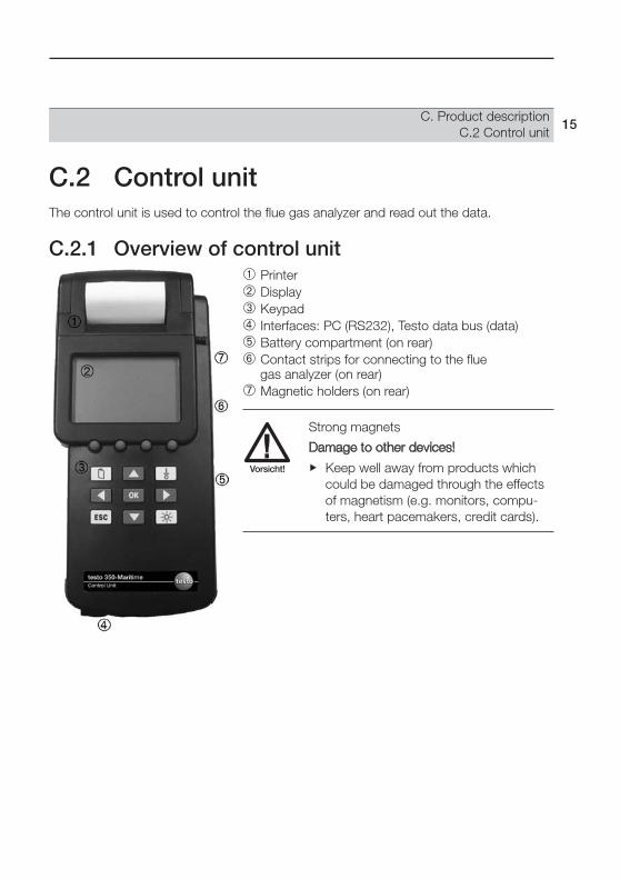
C.2 Control unitThe control unit is used to control the flue gas analyzer and read out the data.
C.2.1 Overview of control unit Printer Display Keypad Interfaces: PC (RS232), Testo data bus (data) Battery compartment (on rear) Contact strips for connecting to the flue
gas analyzer (on rear) Magnetic holders (on rear)
Strong magnets
Damage to other devices!
Keep well away from products whichcould be damaged through the effectsof magnetism (e.g. monitors, compu-ters, heart pacemakers, credit cards).
C. Product descriptionC.2 Control unit
15
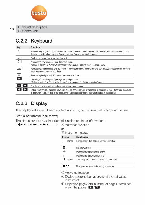
C.2.2 KeyboardKey Functions
Function key (4x): Call up instrument functions or control measurement; the relevant function is shown on thedisplay in the function bar (see Display, section Function bar, on this page
Switch the measuring instrument on/off.
“Readings” view is open: Open the main menu.“Select function” or “Enter value/name” view is open: back to the “Readings” view.
Abort selected processes or a selection or leave submenus. The main menu can always be reached by scrollingback one menu window at a time.
Switch display light on/off or start the automatic timer.
“Readings” view is open: Open system configuration.“Select function” or “Enter value/name” view is open: Confirm a selection/ input.
/ Scroll up/down, select a function, increase/reduce a value.
/ Select function: The function keys may also be assigned further functions in addition to the 4 functions displayedin the function bar. If this is the case, small arrows appear above the function bar in the display.
C.2.3 DisplayThe display will show different content according to the view that is active at the time.
Status bar (active in all views)
The status bar displays the selected function or status information: Activated function or- Instrument status:
Symbol Significance
flashes Error present that has not yet been rectified
Battery warning
Measurement program is active
Measurement program running
rotates Searching for connected system components
Flue gas measurement running alternating
Activated location Device address (bus address) of the activated
instrument Displayed page/ total number of pages, scroll bet-
ween the pages: / .
C. Product descriptionC.2 Control unit
16

Function bar (active in all views)
The function bar shows the function that is currently assigned to the individual functionkeys. The assignment of the function keys can change according to the menu.
The function keys can be configured with the following functions:Function Description
/ Scroll up/down, select a function, increase/reduce a value.Same function as for the / keys.
ESC Abort selected processes or a selection or leave submenus. The main menu can always be rea-ched by scrolling back one menu window at a time.Same function as for the key.
OK “Readings” view is open: Open system configuration.“Select function” or “Enter value/name” view is open: Confirm a selection/ input.Same function as for the key.
Curr. Accept the value currently highlighted.Change Edit the setting.Test Start a test printout.End Accept settings and end the function.
Switch between upper-case and lower-case text.Delete a character in front of the cursor.Insert a space.
Info Display an overview of the settings.Reset value to the factory setting.Add the actual measured/calculated value as an input value.
/ When entering the date/ time: select individual numbers.
Additional functions can be assigned individually, see Assigning a function key, page 36
If an arrow appears above the function bar, it meansthat the / keys can be used to call up furtherfunctions to which a function key was assigned.
Factory setting
C. Product descriptionC.2 Control unit
17

View: Readings
The measurement view displays the readings and the relevant parameters and units ofmeasurement:
Reading Parameter Unit of measurement6 or 3 readings are displayed on each page (this can be set using the Zoom function key).
View is the same as the factory setting.
View: Select function Selected function Available functions; the one currently selected
has a black background
View: Enter values Selected function Minimum/current stored/maximum value that
can be entered Input matrix for selecting the desired numbers;
the selected number has a black background Input value Function bar
View: Enter name Selected function Input matrix for selecting the desired symbols
(letters/numbers/special characters); the selected symbol has a black background
Display of the entered name Function bar
C. Product descriptionC.2 Control unit
18

C.2.4 Setting the automatic switch-off
The automatic switch-off gives you the opportunity to control the control unit so that itswitches itself off if the control unit is not operated within this time. The time before theswitch-off procedure occurs (Auto Off time) can be chosen.
1. Instrument
2. Select the Auto Off menu item with or andpress .
- A pull-down menu appears with the entries: Off, 5min, 10 min, 15 min, 20 min, 25 min, 30 min.
3. Select the desired time for the automatic switch-offof the control unit with or and press .
- The set Auto Off time is applied.
4. The selection menu can be closed with and . The control unit is switched offautomatically after the chosen time.
If Off is selected, the control unit can only be switched off via .
If a measurement program is running with a measuring cycle longer than the auto offtime, the instrument goes into sleep mode after the auto off time and is reactivatedfor the chosen measuring cycle.
C. Product descriptionC.2 Control unit
19

C.2.5 Changing unitsEach parameter can be assigned to a unit. Various systems of units are possible:
1 Instrument .
2 Units .
3 Select Temperature, Humidity or Pressure and confirm with Parameter units
Temperature °C, °FHumidity Off, td°C, g/m3, J/gPressure bar, psi, mmW, Torr, inHg, kPa
C.2.6 Showing/hiding integrated differential pressu-re probe
1. Instrument .
2 Configuration .
3 Select Internal pressure sensor and confirm with
4 Select Show/hide pressure sensor and confirm with .
5 Select Scroll instruments and confirm with
4 Select Current instrument or All instruments and confirm with .
C.2.7 Control unit connections/ interfaces RS232: PC interface Data: Interface to system components
(Testo data bus) Additional probe input Differential pressure
C. Product descriptionC.2 Control unit
20

C.2.8 Control unit power supplyOrdinary or rechargeable batteries must always be inserted in the control unit asotherwise no connection can be established with other system components and thedate/ time setting will be lost.
The batteries/ rechargeable batteries in the control unit are only there to power theclock and establish a connection to the flue gas analyzer. The control unit cannotfunction if it is not connected to an flue gas analyzer. It will switch itself off after 15 s.
Power is supplied by 4 rechargeable batteries/batteries (1.5 V, mignon, type AA).
C.2.9 Air probe (temperature and humidity)Connect the standard air probe (order no. 0636 9740) to the additional probe input via the connecting cable (order no. 0430 0143).
C. Product descriptionC.2 Control unit
21

C.3 Flue gas analyzerThe readings are taken with the help of the flue gas analyzer.
C.3.1 Flue gas analyzer overview
Contact strips for connection to the control unit Status LEDs Particle filter Fresh air inlet filter (fresh air valve option) Gas outlet 1+2 Fresh air inlet Condensate container (see Condensate container, on page 69) Unlocking lever for contact strips
C. Product descriptionC.3 Flue gas analyzer
22

C.3.2 LED status displayThe status LEDs indicate the instrument status of theflue gas analyzer:
Status Display
Power supply (LED ):
Mains operation green/steadyRechargeable battery operation green/ flashing(battery fully charged)Rechargeable battery operation (battery low) red/ flashingBattery recharging, instrument switched off off
Mode (LED ):
Measurement green/steadyFresh air /zeroing green/ flashingError red/ flashing
Battery recharging (LED ):
Recharging battery (rapid charge) green/ flashingBattery fully charged, trickle charge green/steady
C.3.3 Flue gas analyzer connections/ interfaces
Mains supply socket (110/230 V 50/60 Hz) Data: Interfaces to system components (Testo data bus) Dilution air inlet Trigger/alarm: interface for trigger/alarm signal Ambient air temperature (AT) / temperature T2 probe connection Flue gas temperature (FT) / temperature T1 probe connection Flue gas input Pitot tube connections DC Voltage input (11 to 40 V DC)
C. Product descriptionC.3 Flue gas analyzer
23

C.3.4 Flue gas analyzer power supplyThe flue gas analyzer is powered optionally by the integrated mains unit or by the testorechargeable battery pack (0554 1098).
C.3.5 Voltage inputThe flue gas analyzer can also be operated via anexternal voltage source (11 - 40 V DC). The cable with battery terminals and an adapter for connecting the voltage source to the flue gasanalyzer (art. no. 0554 1337) is included in the set.If the flue gas analyzer is switched off, theinstrument’s internal rechargeable battery can be charged via an external voltage source (11 - 40 V DC).
C.3.6 Instrument options Only one SO2 cell is available as an option (on request).
C. Product descriptionC.3 Flue gas analyzer
24

C.4 Flue gas probeAvoid electrical hazards:
Never use the measuring instrument and probes to measure on or near live parts!
Product safety/preserving warranty claims:
Temperatures given on probes/probes relate only to the measuring range of the sen-sors. Do not expose handles and feed lines to any temperatures in excess of 70 °Cunless they are expressly permitted for higher temperatures.
Carry out only the maintenance and repair work that is described in the instructionmanual. Follow the prescribed steps exactly. For safety reasons, use only originalspare parts from Testo.
Any additional work must only be carried out by authorized personnel. Testo willotherwise refuse to accept responsibility for the proper functioning of the measuringinstrument after repair and for the validity of certifications.
The measuring instrument must not be placed on surfaces subject to extremely highvibration.
Operate the measuring instrument in its case in accordance with its intended purpose.
Before use: It is imperative that you observe the fitting instructions for the flue gasprobe.
Preliminary filter Cone mounting flange Probe shaft cone Probe shaft Probe handle with connections
for probe shaft and gas tubes/Thermocouple line
Thermocouple Gas tube Positive pressure release tube
C. Product descriptionC.3 Flue gas analyzer
25

C.4.1 Positive pressure terminalThe max. positive pressure of the flue gas at the measurement gas inlet of the testo 350-MARITIME is 50 hPa (~510 mm WS).
The additional hose is used to compensate the positive pressure of 50 hPa (~510 mm WS) in the flue gas system for sampling points with positive pressure. If thereis no positive pressure, the positive pressure terminal must be closed in order to preventthe intake of external air and consequently an incorrect measurement.
D. CommissioningThis chapter describes the steps required to commission the product.
Control unit
Remove the protective film from the display.
There must always be batteries or rechargeable batteries in the control unit as otherwise it will not be possible to establish a connection to other system components.
The control unit is supplied with a rechargeable battery pack (0554 1097) already inserted.
Flue gas analyzer:
The flue gas analyzer is supplied with a rechargeable battery pack (0554 1098) alreadyinserted.
Charge the rechargeable battery fully before using the flue gas analyzer (see Chargingthe battery).
To power the flue gas analyzer, connect the integrated mains unit and the mains leadto the mains port of the flue gas analyzer or to the line to the voltage source.
On ships where there is no stable mains voltage, the flue gas analyzer should ideallybe operated with the voltage source (11 - 40 V DC) or with a suitable mains filter.
Operation via the integrated mains unit or the DC voltage source is recommended for longer measurements.
To guarantee the reliability of the data connection, it is recommended that the control unit and the flue gas analyzer be connected using the connecting cable (art. no. 0449 0042 included in the set).
D. Commissioning26
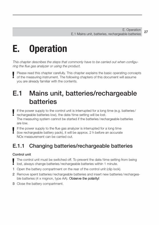
E. OperationThis chapter describes the steps that commonly have to be carried out when configu-ring the flue gas analyzer or using the product.
Please read this chapter carefully. This chapter explains the basic operating conceptsof the measuring instrument. The following chapters of this document will assumeyou are already familiar with the contents.
E.1 Mains unit, batteries/rechargeablebatteries
If the power supply to the control unit is interrupted for a long time (e.g. batteries/rechargeable batteries low), the date/ time setting will be lost. The measuring system cannot be started if the batteries/ rechargeable batteries are low.
If the power supply to the flue gas analyzer is interrupted for a long time (low rechargeable battery pack), it will be approx. 2 h before an accurate NOx measurement can be carried out.
E.1.1 Changing batteries/rechargeable batteries
Control unit
The control unit must be switched off. To prevent the date/ time setting from beinglost, always change batteries/ rechargeable batteries within 1 minute.
1 Open the battery compartment on the rear of the control unit (clip lock).
2 Remove spent batteries/ rechargeable batteries and insert new batteries/ rechargea-ble batteries (4 x mignon, type AA). Observe the polarity!
3 Close the battery compartment.
E. OperationE.1 Mains unit, batteries, rechargeable batteries
27

Flue gas analyzer
The flue gas analyzer must not be connected to a mains socket or to a DC voltagesupply. The flue gas analyzer must be switched off.
1 Open the battery compartment on the rear of the flue gas analyzer (2 cliplocks, ).
2 Remove the rechargeable battery packfrom the battery compartment and disconnect the connector .Only use the Testo rechargeable battery pack 0554 1098). When inserting the rechargeable battery pack,make sure that the connecting cablesdo not get kinked or squashed.
3 Connect the connector of the newrechargeable battery pack in the battery compartment and insert therechargeable battery pack into thecompartment.
4 Close the battery compartment.
E.1.2 Charging the batteryControl unitCharging the rechargeable batteries in the control unit takes place via the flue gas analyzer.
Flue gas analyzer
The rechargeable battery pack can only be charged at an ambient temperature of ±10 - +25 °C. If the battery has discharged completely, the charging time at roomtemperature is approx. 4-5 h.
The flue gas analyzer must be switched off. It is not possible to charge the recharge-able battery pack during operation.
Connect the cable with battery terminals to the flue gas analyzer or the flue gas ana-lyzer to a mains socket.
- The charging process will start automatically. The charge status is indicated on the“Battery charging” LED:Status LED display
Recharging battery (rapid charge) green/ flashingBattery fully charged, trickle charge green/steady
- The fan of the flue gas analyzer can run during the charging process.
E. OperationE.1 Mains unit, batteries, rechargeable batteries
28

Rechargeable battery care
Do not let the rechargeable battery pack discharge completely; when the batterywarning symbol ( ) lights up, charge the rechargeable battery pack as soon as possible.
Only store the rechargeable battery charged and at low temperatures, although notbelow 0°C. During long periods of disuse, discharge and recharge the rechargeablebattery pack every 3 - 4 months. Trickle charge for no longer than 2days.
E.1.3 Mains operation (110/230 V, 47 - 63 Hz)Connect the mains cable to the flue gas analyzer and a mains socket.
- The flue gas analyzer is powered via the mains unit.
- If the flue gas analyzer is switched off and a rechargeable battery pack is inserted, thecharging process will start automatically. Battery charging stops when the measuringsystem is switched on using the control unit.
E.1.4 Operation with DC voltage (11 V - 40 V DC)Connect the cable with battery terminal and adapter (art. no. 0554 337) to the flue gas analyzer and to a designated port.
- If the flue gas analyzer is switched off and a rechargeable battery pack is inserted, the charging process will start automatically. Battery charging stops when the measuring system is switched on using the control unit. It is not possible to chargethe rechargeable battery pack when measuring.
E. OperationE.1 Mains unit, batteries, rechargeable batteries
29

E.2 Probes/sensors
E.2.1 Connecting probes/sensorsProbe detection is carried out during the activation process: Probes that are requiredmust always be connected before the flue gas analyzer is switched on, or the fluegas analyzer must be switched off and then on again after a change of probe, so thatthe correct data can be read.
Connect the required probes/sensors to the corresponding connections.
The flue gas temperature is measured via the thermocouple at the tip of the flue gasprobe below the probe filter.
E.2.2 Positioning flue gas probe
E.2.2.1 Flue gas flow with characteristics comparable tothose in the centre of the flow
The tip of the probe must be in the centre of the flue gas flow.
Align the flue gas probe in the flue gas duct so that the tip is in the area of the highest flue gastemperature.
Do not take readings around the edges.
Measure at distance of min. 3x diameter of flue gas boiler from last elbow.
E. OperationE.2 Probes/sensors
30

E.2.2.2 Flue gas flow without characteristics comparable tothose in the centre of the flow
Preliminary filter
Probe shaft
Insulation
Cone
Handle
Flue gas duct
The immersion depth is dependent on the thickness of the insulation of the flue gasduct. If the flue gas is measured immediately downstream of the flue gas turbocharger,the flue gas in the flue gas duct is extremely homogenous due to the good mixing, i.e.there is no centre of flow. It is therefore not necessary to place the probe shaft in anexact position.
E.2.3 Options for securing the flue gas probeTo avoid damage to the instrument, the engine system or persons, specialprecautions must be taken to secure the flue gas probe if the flue gas duct is subject to strong vibration. Securing it simply by screwing in the probecone will not hold permanently or provide a long-term tight fit if there isstrong vibration.
The probe must be positioned so that no damage to the engine system can be caused by parts attached to the flue gas probe falling off or the probe fracturing.
Only leave the flue gas probe in the flue gas duct while measuring is in pro-gress. Once measuring is finished, remove the probe from the flue gas duct.
If the end of the probe is hanging freely, it must be fixed/supported with anappropriate mechanism in addition to the probe fixture. Otherwise there is a risk that the probe will fracture.
E. OperationE.2 Probes/sensors
31
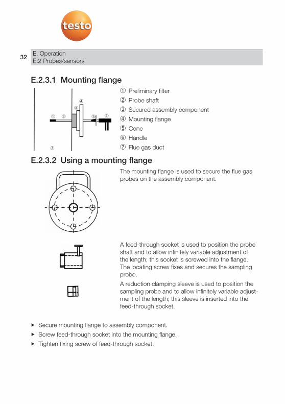
E.2.3.1 Mounting flange Preliminary filter
Probe shaft
Secured assembly component
Mounting flange
Cone
Handle
Flue gas duct
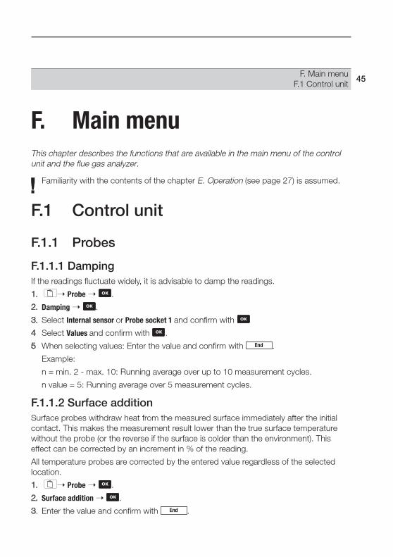
E.2.3.2 Using a mounting flangeThe mounting flange is used to secure the flue gasprobes on the assembly component.
A feed-through socket is used to position the probeshaft and to allow infinitely variable adjustment of the length; this socket is screwed into the flange. The locating screw fixes and secures the samplingprobe.
A reduction clamping sleeve is used to position thesampling probe and to allow infinitely variable adjust-ment of the length; this sleeve is inserted into thefeed-through socket.
Secure mounting flange to assembly component.
Screw feed-through socket into the mounting flange.
Tighten fixing screw of feed-through socket.
E. OperationE.2 Probes/sensors
32

E.2.3.3 Using a cone Preliminary filter
Probe shaft
Cone
Handle
Flue gas duct
Align the flue gas probe in the flue gas duct so that the tip is in the area of the highestflue gas temperature.
Tighten cone firmly.
E.2.3.4 Use welded-on shaft Preliminary filter
Probe shaft
Welded-on shaft
Cone
Handle
Flue gas duct
Align the flue gas probe in the flue gas duct.
Tighten cone firmly.
E.2.4 Vibrations Preliminary filter
Probe shaft
Cone
Handle
Flue gas duct
Secure cone in the sampling point and seal
Ensure that no attached parts can fall into the flue gas shaft.
If the end of the probe is hanging freely, stabilize the probe with appropriate means.
E. OperationE.2 Probes/sensors
33

E.3 Basic operating steps
E.3.1 Connecting the control unit to the flue gasanalyzer
Only one flue gas analyzer can be connected to the control unit.
Connection using contact strips
1 Place the control unit on the flue gas analyzer sothat the guide nose on the left side of the controlunit () is above the guide groove of the flue gasanalyzer ().
2 Press the control unit against the flue gas analyzeruntil you hear it engage.
Connection using a data bus cable (included in the set)Only use Testo data bus cables. Do not lay data bus cables near power cables.Connect the data bus cable to the “Data” ports of the control unit and flue gas analyzer.
E.3.2 Switching on the flue gas analyzerBefore switching the flue gas analyzer on, check that:
· The control unit is correctly connected to the flue gas analyzer.· All the necessary probes/sensors are connected.· The power supply of all system components is guaranteed.
Measuring the ambient air temperature (AT)If no ambient air temperature sensor is connected, the temperature measured by thethermocouple of the flue gas probe during the zeroing phase is used as the ambient airtemperature. All dependent parameters are calculated using this value. This method ofmeasuring ambient air temperature is sufficient for systems dependent on ambient air. The fresh air required for the zeroing phase is drawn in through the fresh air inlet. Theflue gas probe may therefore already be in the flue gas duct before or during the zeroingphase.During the zeroing phase, the measuring instrument verifies the zero point and the driftof the gas sensors. The O2 sensor is also set to 21%O2.
E. OperationE.3 Basic operating steps
34

If an ambient air temperature sensor is connected, the ambient air temperature is measured continuously via this sensor.The flue gas probe may already be in the flue gas duct during the zeroing phase.
Zeroing phase
During the zeroing phase
- the measuring cells of the flue gas analyzer are zeroed.
- no interfering gases (e.g. CO, NO) may be present in the ambient air!
Switching on:
1. Press .
- The initialization screen is displayed and the data bus is scanned for connectedsystem components (this takes up to 60 s).
- The zeroing phase starts (this takes 60 s).
- Measurement view is opened.
2. Access the selection window using the key.
3. Choose between the control unit and flue gas analyzerusing the , arrow keys.
4. Confirm with key.
Switching off:
1. Press .
E.3.3 Calling up a functionFunctions can be called up using function keys or from a selection list.
Calling up a function using a function key
Only particular functions can be called up using a function key, see Display, sectionFunction bar, page 17.
If an arrow appears above the function bar, it meansthat the / keys can be used to call up furtherfunctions to which a function key was assigned.
Press the function key that is assigned the desired function.
E. OperationE.3 Basic operating steps
35

Calling up a function using a selection list
Selection lists appear e.g. when the main menu is called up (press in measurementview).
1 Select function: or press .
- The selected function is shown with a black background.
2 Confirm selection: Press .
- The chosen function is opened.
E.3.4 Assigning a function keyThe function keys that are shown on the display depend on the view that is selected.Only the function keys that can be used in the particular view are displayed.
- The measurement view is opened.
1 Press , release and immediately afterwards press the function key to be assigned.
- A selection list showing the functions that can be assigned to a function key appears.
2 Select the function with or and confirm with :Function Description
PStart, PStop Start the measuring gas pump and display readings or stop the measuring gas pump (the function key switches between the two options automatically)
Zoom Zoom in (display 6 or 3 readings per page)v On, v Off Zero the pressure sensor and activate flow measurement or switch off flow measurement
(the function key switches between the two options automatically)Save Save readingsStart, Stop Start or stop the measurement program (the function key switches between the two options
automatically)Print Print readingsLF Pr Activate the printer line feedZero Start the zeroing phase manually (duration: 60 s)Diag. Display unrectified errorsdP Activates the separate differential pressure measurement in the flue gas analyzer.Gas (air) Manual change from measuring gas to ambient air.CO off Manual disconnection and rinse with fresh air.CO on Manual connection of a deactivated CO sensor to the gas path.(empty) The function key does not trigger any function
E. OperationE.3 Basic operating steps
36

E.3.5 Air humidity/temperature of engine intake airThe ambient humidity and temperature of the intake air of the turbocharger must be factored in to ensure that the flue gas values are calculated correctly in accordance with NOx-TC and MEPC.103(49).
The following values are stored as factory settings:
· Ambient humidity: 80% RH.
· Ambient temperature 20 °C
In order to factor the respective current ambient conditions into the measurement, it is recommended that the air probe (temperature and rel. humidity) with order no. 0636 9740 be connected to the control unit via the connecting cable (length 1.5 m)with order no. 0430 0143.
If the respective current ambient conditions are already known without using the Testo air probe, the factory settings can be overwritten with the current values using the input editor.
E.3.5.1 Accepting the current readingThe data of the air probe is recorded once when the gas sensors are zeroed and thenused permanently for this series of measurements. The current values of the air probeare thus adopted each time the instrument is zeroed again.
Some functions require values (figures) or a name (characters) to be entered. Inputs aremade using an input editor.
Input editor for values
1 Select the value (character): Press , , ,.
2 Accept the value: Press .
Options:
Accept current reading from connected airprobe (art. no. 0636 9740): .
Delete a character in front of the cursor: .
Accept the value currently highlighted: .
Select individual number (only when inputtingdate/ time): , .
3 Repeat steps 1 and 2 as required.
4 Accept settings: Press .End
Curr.
E. OperationE.3 Basic operating steps
37

Input editor for names
1 Select the value (character): Press , , ,.
2 Accept the value: Press .
Options:
Switch between upper-case and lower-case letters: .
Delete a character in front of the cursor: .
Insert space: .
3 Repeat steps 1 and 2 as required.
4 Accept settings: Press .
E.3.6 Printing dataTo print readings, a function key must be assigned the Print (Print readings) function, seeAssigning a function key, page 36.
Only those readings that were assigned a display field in the Measurement view will beprinted.
E.3.6.1 Printing the current readingsTo print readings: .
The measurement data that are currently stored can be printed out while ameasurement program is running.
1 Open the Main menu: Press .
2 Memory Read out .
3 Select the protocol for the current measurement and confirm with .
4 Print readings: .Print
End
E. OperationE.3 Basic operating steps
38

E.3.6.2 Printing stored readings1 Open the Main menu: Press .
2 Memory Read out .
3 Select the measurement protocol with and confirm with .
4 Press function key.
The readings are printed column by column.
E.3.7 Saving dataTo save readings, a function key must be assigned the Save (Save readings) function,see Assigning a function key, page 36.
Only those readings that were assigned a display field in the Measurement view will besaved.
To save readings: .
E.3.8 Switching off the flue gas analyzerUnsaved readings are lost when the flue gas analyzer is switched off!Rinse phase
During the rinse phase the gas sensors of the flue gas analyzer are rinsed with fresh air.The duration of the rinse phase depends on the gas concentration in the measuringcells. The rinse phase is ended once a certain threshold value is reached.
Switching off:
Press .
- The rinse phase starts.
- The measuring system switches itself off. It is normal for the fan of the flue gas analy-zer to run on for a while.
- If the flue gas analyzer is connected to a mains socket and a rechargeable batterypack is inserted, the charging process will start automatically.
Save
E. OperationE.3 Basic operating steps
39

E.4 Setting the measuring system up
E.4.1 Setting the language- The measurement view is opened.
1 Open the Main menu: Press .
2 Service Sprache or Lang. .
3 Select the language and confirm with .
E.4.2 Setting the date/time- The measurement view is opened.
- No measurement program is active (otherwise the function is locked).
1 Open the Main menu: Press .
2 Instrument Change date .
3 Select the date or time with , and press .
- The input editor is opened.
4 Enter values and accept settings with .End
Edit
E. OperationE.4 Setting the measuring system up
40

E.4.3 Setting the fuel- The measurement view is opened.
1 Open the Main menu: Press .
2 Input Fuel .
The following fuels can be selected in the flue gas analyzer:Fuel DescriptionDistillate fuel oil (DM) DMX
DMADMBDMC
Residual fuel oil (RM, RFO) RMA 30RMB 30RMD 80RME 180RMF180RMG 380RMG 380RMH 380RMK380RMH 700RMK 700
Rapeseed Oil Methyl Ester (RME) RME (FAME)Test gas Test gasUser-defined 1 Fuel 1User-defined 2 Fuel 2Low-sulphur diesel (0.1% sulphur) MDO 0.1% S
3 Select the fuel and confirm with .
E.4.3.1 Select user-defined fuel- The measurement view is opened.
1 Open the Main menu: Press .
2 Input Fuel .
3 Select Fuel1/Fuel2 with ,
- Coefficient information window for fuel1/fuel2 - H content (hydrogen content), factory setting 13.6%
- C content (carbon content), factory setting 86.2%
- S content (sulphur content), factory setting 1.5% are displayed
4 Select hydrogen content, carbon content or sulphur content with , confirmwith .
- The input editor is opened.
Change
E. OperationE.4 Setting the measuring system up
41

5 Enter the values
- H content adjustment range: 0.1...99.9%
- C content adjustment range: 0.1...99.9%
- S content adjustment range: 0.0...5.0%
6 Accept settings with .
E.4.4 Changing the display sequenceOnly those parameters and units of measurement to which a display field was assignedin the measurement view are displayed in the measurement view, in the saved measure-ment protocols and on printouts of readings.
The assignment of parameters/units of measurement to the individual display fields inthe Measurement view can be changed. The following parameters and units are availa-ble (may vary from one instrument to another):
- The measurement view is opened.
1 Open the Main menu: Press .
2 Instrument View .
- The parameter and the unit of the display fields is displayed.
3 Select the display field to be changed with , , , and confirm with .
Options:
Insert a new display field: Insert .
Delete the current display field: Delete .
4 Select Parameter and confirm with .
Display Parameter Units
Itemp Instrument temperature °C, °FB/h Operating hours hPump Pump output l /mSpeed Flow speed m/sFuel Fuel -NOxt NOx display value corrected
for CLD (chemiluminescence)This display value is based on ppm %dry flue gas.
NOxn NOx display value correctedfor CLD (chemiluminescence)This display value is based on ppm %wet flue gas.
SO2n Based on wet flue gas ppm %H2Ob Calculated moisture content
of fuel %Pabs Absolute pressure hPa
Display Parameter Units
O2 Oxygen %CO Carbon monoxide ppm, %NO Nitrogen monoxide ppm, %SO2 Sulphur dioxide ppm, %NO2 Nitrogen dioxide ppm, %H2 Hydrogen ppmNOx Nitrogen oxides ppm, % (addition of NO and NO2)FT Flue gas temperature °C, °FAT Ambient air temperature °C, °FCO2i Carbon dioxide %dP Differential pressure mbar, hPa,
mmWS, inWRech. batt. Rechargeable battery voltage V
Flue gas analyzer
End
E. OperationE.4 Setting the measuring system up
42

5 Select the parameter that is to be assigned to the display field and confirm with .
6 Select the unit of measurement that is to be assigned to the parameter and confirmwith .
E.4.5 Setting up locationsThe memory in the testo 350-MARITIME is organized in such a way that what is knownas a “location” must be activated to identify a saved measurement. The default locationis called Noname.
On saving, readings are assigned to whichever location is active at the time of saving.Several measurements can be saved for each location. It is also possible to organizelocations in folders/subfolders.
The maximum possible number of measurements that can be saved depends on whet-her each individual measurement is saved under its own location or all measurementsare stored exclusively under one location.
The saved messages are stored consecutively with the respective date and time andcan therefore be selected easily.
Unsaved readings are lost when the measuring instrument is switched off!
Creating/copying/editing/deleting folder/ location:
- The measurement view is opened.
1 Open location management: and press .
- Available folders ( ) and locations ( ) are displayed.
If the folder / location is to be created in an existing folder: Select the folder andconfirm with .
If a folder / location is to be edited, deleted or copied: Select the folder so that it isgiven a colour background.
2 Press .
Options:
To print saved measurement data records of the selected location: Print location .
To display information about the selected location: Info .
3 Select the desired option and confirm with .
4 When creating, copying or editing a folder / location: Enter the name and confirm with . End
Edit
E. OperationE.4 Setting the measuring system up
43

Activating a location:
- The measurement view is opened.
1 Open location management: and press .
- Available folders ( ) and locations ( ) are displayed.
2 Select the desired folder or location and confirm with .
If a folder was selected: Repeat the process.
- Measurement view is opened.
E.4.6 Changing the instrument name- The measurement view is opened.
1 Open location management: Press .
2 Press .
- The connected instruments are displayed.
3 Select the instrument and press .
4 Enter the name and confirm with .
E.4.7 Set up printerThe control unit must be switched off.
1 Open the printer paper compartment: Hold thecover by the recesses on the sides and pullupwards ().
2 Push the start of the paper roll as far as possibleinto the infeed with the outside (= printable side)facing down ().
3 Switch on the control unit Press .
4 Press 12 or 13 times during the initialization phase to draw the paper in (). Thepaper may have to be pushed in gently by handuntil the forwarder roller picks it up.
5 Place the paper roll into the paper compartment() and close the paper compartment.
LfDr
End
Edit
E. OperationE.4 Setting the measuring system up
44
F. Main menuThis chapter describes the functions that are available in the main menu of the controlunit and the flue gas analyzer.
Familiarity with the contents of the chapter E. Operation (see page 27) is assumed.
F.1 Control unit
F.1.1 Probes
F.1.1.1 DampingIf the readings fluctuate widely, it is advisable to damp the readings.
1. Probe .
2. Damping .
3. Select Internal sensor or Probe socket 1 and confirm with
4 Select Values and confirm with .
5 When selecting values: Enter the value and confirm with .
Example:
n = min. 2 - max. 10: Running average over up to 10 measurement cycles.
n value = 5: Running average over 5 measurement cycles.
F.1.1.2 Surface additionSurface probes withdraw heat from the measured surface immediately after the initialcontact. This makes the measurement result lower than the true surface temperaturewithout the probe (or the reverse if the surface is colder than the environment). Thiseffect can be corrected by an increment in % of the reading.
All temperature probes are corrected by the entered value regardless of the selectedlocation.
1. Probe .
2. Surface addition .
3. Enter the value and confirm with .End
End
F. Main menuF.1 Control unit
45

F.1.1.3 Temp. probe adjustmentTemperature probes with EEPROM can be adjusted to a reference temperature, e.g. using a calibration bath. The reference temperature is preferably present at the wor-king point of the temperature probe. Following the adjustment, the temperature readingsfrom this probe are then correspondingly altered, e.g. an offset correction takes place. An adjustment is only possible with an EEPROM temperature probeconnected to the control unit.
1. Probe .
2. Point .
3. Enter the value and confirm with
F.1.1.4 Hum. probe adjustmentThe 0636.9740 air probe is adjusted via the control unit (Control and adjustment set forhumidity sensors 0554 0660).
1. Probe .
2. Calibr. .
3. Perform adjustment.
No reset can be carried out for the humidity adjustment.
F.1.1.5 ScalingScaling can be performed for the current/voltage cable (order no. 0554.0007).
1. Probe .
2. Scaling .
3. Perform scaling.
F.1.1.6 ResetInternal sensor, Probe socket 1 and/or All probes can be reset to the factory setting.
The following is reset:
• the set damping
• the surface addition
• the adjustment
• and the scaling
End
F. Main menuF.1 Control unit
46

1. Probe .
2. Reset .
3. Select Internal sensor, Probe socket 1 or All probes and confirm with .
F.1.1.7 InfoInformation about adjusted probes.
1. Probe .
2. Info .
3. Select Internal sensor, Probe socket 1 and confirm with
F.1.2 Instrument
F.1.2.1 Change date Setting the date/ time
- No measurement program is active (otherwise the function is locked).
1 Instrument .
2 Change date .
3 Select the date or time .
4 Enter the values .
F.1.2.2 Auto off see Chapter C.2.4 Switch-off, page 19
F.1.2.3 Printer
Setting the contrast
1 Instrument .
2 Printer .
3 Contrast .
4 Set the contrast with , .
Option:
Start a test printout: .
5 .End
Test
End
Edit
F. Main menuF.1 Control unit
47

Entering header/ footer text
To document the assigned company and the assigned employee, it is possible to enterprinted texts: Three lines and one footer can be filled variably with numbers and letters.
1 Instrument .
2 Printer .
3 Print text .
4 Select the line .
5 Enter the text .
F.1.2.4 LightSwitching the display light on/off.
On/off
The display light is switched on/off via . After switching on, the display light must beactivated by pressing the key.
Automatic
The display light is switched on when the control unit is switched on. The display light isswitched off automatically after 3 minutes. By pressing , the display light remains onfor an additional 3 minutes.
1 Instrument .
2 Lighting .
3 Select On/Off or Automatic and confirm with .
The lighting reduces the running time of the control unit in battery operation. Use thelighting only when needed.
F.1.2.5 Diagnosis
In the event of problems and malfunctions, the fault description and possible remedialmeasures are described
1 Instrument .
2 Diagnosis .
1.2.6 Units
see Chapter C2.5 Changing units, page 20
End
F. Main menuF.1 Control unit
48

F.1.2.7 Configurationsee Chapter C2.6 Showing/hiding integrated differential pressure probe, page 20
F.1.3 Service
F.1.3.1 Operating values
Displaying operating values:
1 Service .
2 Operating values .
F.1.3.2 Reset Factory
Displaying operating values:
1 Service .
2 Reset Factory .
3 Yes or No and confirm with .
4 If Yes is selected: The values are reset to the factory setting.
F.1.3.3 Address
Displaying the Testo service address:
1 Service .
2 Address .
F.1.3.4 Instrument data
Displaying instrument data:
1 Service .
2 Instrument data .
F.1.3.5 Language
Setting the menu language:
1 Service .
2 Sprache or Lang. .
3 Select the language .
F. Main menuF.1 Control unit
49
F.2 Flue gas analyzer
F.2.1 Memory
F.2.1.1 Reading out
Viewing/printing saved measurement data:
1 Memory .
2 Read out .
3 Select the measurement data record.
Option:
View the properties of the measurement data record: , return with .
4 Confirm with .
Option:
Print a measurement data record: .
F.2.1.2 ProgramInstrument settings cannot be changed if a program is active or running.
Saving (= activating) a measurement program:
1 Memory .
2 Program .
3 Select the measurement program and confirm with .
4 Select Save and confirm with .
- The measurement program is activated.
Deleting (= deactivating) a measurement program:
1 Memory .
2 Program .
3 Select the measurement program and confirm with .
4 Delete .
- The measurement program is deactivated (not deleted!).
Information
F. Main menuF.2 Flue gas analyzer
50
View the properties of the measurement program:
1 Memory .
2 Program .
3 Select the measurement program.
4 Press - or -
Info .
- The properties of the selected measurement program are displayed.
5 To leave the function without activating a program: .To leave the function and activate a program: .
Editing a measurement program:
1 Memory .
2 Program .
3 Select the measurement program and confirm with .
4 Select the first parameter for defining the measurement program and confirm with .
5 Enter the properties/values and confirm.
6 Repeat the process for other parameters.
Long-term measurement of flue gasProgramming the instrument
No settings can be made on the instrument while the program is active.
Enter values according to the measurement task:
1 Memory Program Start
Start criteria:· Manual:
By pressing the Start function key in the measurement menu.· Date/time:
Beginning of measurement at the selected date/selected time2 Enter the start criterion.
Information
F. Main menuF.2 Flue gas analyzer
51

3 Confirm with .
- Program jumps automatically to the mean calculation:
· With Mean Yes , only the mean values are stored:The measuring rate is the storage cycle of the mean values.
· Mean of mean values:The instrument stores a mean value of all the mean values. Once themeasurement data have been retrieved from the memory, this mean value is marked with *.
4 Enter the measuring rate.
- Program jumps automatically to the selection of the end criterion:Memory fullNumber of valuesDate/Time
5 Enter the values and confirm with End.
- Program jumps automatically to the selection of the gas time cycle (= flue gas measurement).
6 Enter the gas time and confirm.
The pump is stopped when a threshold concentration is reached (e.g. O2 > 20.5%).Reason: low wear and power consumption.
- Program jumps automatically to the selection of the rinse time cycle:
7 Enter the rinse time and confirm.
- An overview of a programmed long-term measurement appears.
8 Confirm measurement program with .
- Measurement program is accepted and configured:
9 Press the Start function key.
- Long-term measurement begins:symbol indicates that a program is running.
The long-term measurement starts with the fresh air/rinse phase:
F. Main menuF.2 Flue gas analyzer52

Fresh air time between measuring cycles:
Minimum and maximum measuring and fresh air cycles:Measuring cycles: 2 min ... 240 min (4 h)Fresh air cycles: 5 min ... 1,440 min (24 h)
10 Stop the programmed measurement early with Stop.
- The measurement program stays activated (indicated by the symbol).
- At the end of the measurement program there is a rinse phase of 2 min (pump runs on).
Restarting the measurement programPress the Start function key.
- The measurement program starts again.
Deleting the instrument’s programming1 Select Memory Program Delete.
The measurement program is only deactivated and not deleted.
2 Select Memory Program Info.
- The measurement program that was last set will be displayed.
3 Reactivate by pressing the function key.
F.2.1.3 Delete memory
Deleting the entire memory (folders, locations and measurement data):
1 Memory .
2 Delete memory .
3 No : Cancel the function.- or -Yes : Clear the memory.
F.2.1.4 Free memory
Viewing free memory space:
1 Memory .
2 Free memory- .
F. Main menuF.2 Flue gas analyzer
53

F.2.2 Sensors
F.2.2.1 Calibration/readjustmentCO, SO2, NO2, NO and O2 sensors can be tested (calibrated) and readjusted; theCO2(IR) sensor can be readjusted. A readjustment of O2 only lasts until zeroing is performed. Calibration data are stored in the sensor, not in the instrument! The relevantcalibration specifications in the applicable standards/guidelines must be observed.
If readings displayed are obviously unrealistic, the measuring cells should be checkedand readjusted as required. To ensure that specific accuracies are retained, Testorecommends testing every six months and readjustment when required.
Dangerous gases
Danger of poisoning!
Observe safety regulations/accident prevention regulations when hand-ling test gases.
Use test gases in well ventilated rooms only.
Before calibrating/readjusting, select the fuel “test gas” (see Setting the-fuels, page 41)
Once the calibration/readjustment has been successfully completed, it is essential thatthe fuel from the application is reset in order to avoid incorrect measurement results.
Recommended test gas concentrations
In order to achieve the maximum sensor accuracy possible, the following test gas concentrations and test gas compositions are recommended:Parameter Meas. range
CO 500 ppm (in N2)CO2 10% (in N2)NO 1000 ppm (in N2)NO2 100 ppm (in synthetic air)SO2 1,000 ppm (in N2) (maximum)
Readjustment with low gas concentrations can lead to deviations in accuracy in theupper measuring ranges. Sensor protection (Switch-off function) is not deactivated inreadjustment. The test gas concentration should therefore be lower than the setthresholds for the sensor protection.
F. Main menuF.2 Flue gas analyzer
54
The following conditions must be met when readjusting:· Use absorption-free tube material· Switch the measuring instrument on at least 20 min before readjustment (warming-up)· Use clean air for gas zeroing· Maximum overpressure of the test gas: 30 hPa (recommended: unpressurized via
bypass)· Charge the test gas for at least 3 minThe Recal. function can be protected by means of a password. The password may becustomized, see Parameter.
Performing CO2(IR) readjustment:
A zeropoint calibration must be performed before CO2(IR) is readjusted. Gradient adjust-ment (2nd calibration point) can be carried out subsequently if necessary.
The zeropoint calibration requires a test gas of 0% CO2 or a CO2 filter (absorption filter).If using a CO2 filter, please follow the corresponding instructions for use.
At ambient temperatures of <10 °C, the warm-up time required by the CO2 IR sensorto reach full measuring accuracy is short. At -5 °C, it is typically 15 min.
Checking the CO2 module
Check the CO2 module at regular intervals using the absorption filter in order to obtainaccurate readings.
The instructions for use enclosed with the CO2 filter set out how the filter should be handled.
The CO2 value displayed should be < 0.3% CO2. If the value is any higher than this, azeropoint calibration and where necessary a gradient calibration must be performed.
1 Sensors .
2 Recal. .
3 If password protection is activated: Enter the password .
4 CO2i .
5 Connect the CO2 filter or apply test gas (0% CO) and confirm with .
- A rinse phase is started.
6 When the rinse phase is over start zero point calibration with .
- Once a stable actual value is reached, the zero point is automatically calibrated.
7 Repeat zero point calibration: Zeropoint calibration .- or -End the function:
Start
End
F. Main menuF.2 Flue gas analyzer
55

- or -Perform gradient calibration: Gradient .
8 Enter the test gas concentration (nominal value) .
9 Start gradient adjustment with .
- Once a stable actual value is reached, the gradient is automatically calibrated.
A test gas check can be carried out to check the readjustment:
10 End the function without carrying out a check: - or -Carry out a check: .
11 Enter the test gas concentration (nominal value) (or a different concentration as inrecalibration) .
- Once a stable actual value is reached, the result of the test gas check is displayed.
12 Save the nominal value/actual value and date/ time of the test without adjusting thesensor and end the function: .
Calibrating/readjusting CO/NO2/NO/O2 sensors:
1 Sensors .
2 Recal. .
3 If password protection is activated: Enter the password .
4 Select the sensor .
5 Enter the test gas concentration (nominal value) .
6 Charge the sensor with test gas and wait until the actual value is stable.
7 Save the nominal value/actual value and date/ time of the test without adjusting thesensor and end the function: .-or-Adjust sensor: .
A test gas check can be carried out to check the readjustment:
8 End the function without carrying out a check: - or -Carry out a check: .
9 Enter the test gas concentration (nominal value) (or a different concentration as inrecalibration) .
10 Charge the sensor with test gas and wait until the actual value is stable.
11 Save the nominal value/actual value and date/ time of the test without adjustingthe sensor and end the function: .Save
End
OK
Save
End
End
Save
Start
Start
Start
F. Main menuF.2 Flue gas analyzer
56
Calibrating/readjusting SO2 sensor
While carrying out steps 6 to 10, the measuring instrument must continuously beconnected to test gas!
1 Sensors .
2 Recal. .
3 If password protection is activated: Enter the password .
4 Select the sensor .
5 Enter the test gas concentration (nominal value) .
6 Charge the SO2 sensor with test gas and wait until the actual value is stable.
7 Save the nominal value/actual value and date/ time of the test without adjusting thesensor and end the function: -or-Adjust SO2 sensor: .
8 Continue test gas connection until the actual value is stable.
9 Save the nominal value/actual value and date/ time of the test without adjusting thesensor and end the function: .-or-End adjustment of SO2 sensor: .
A test gas check can be carried out to check the readjustment.
10 End the function without carrying out a check: - or -Carry out a check: .
11 Enter the test gas concentration (nominal value) (or a different concentration as inrecalibration) .
12 Charge the sensor with test gas and wait until the actual value is stable.
13 Save the nominal value/actual value and date/ time of the test without adjusting thesensor and end the function: .Save
End
OK
Save
OK
Save
Ende
End
F. Main menuF.2 Flue gas analyzer
57

F.2.2.2 Printing sensor dataPrinting saved sensor data:
1 Sensors .
2 Print sensor data .
F.2.2.3 Sensor status
Display the adjustment date, sensitivity of the sensors and filter life (in ppmh):
1 Sensors .
2 Sensor status .
- CO and NO filter life is displayed and can be printed out.
Example calculation for 350 ppm SO2 and 600 ppm NOx and 4 h measurement/dayCO sensor600 ppm NOx + 350 ppm SO2 x 4 h/day = 3,800 ppmh/day275,000 ppmh / 3,800 ppmh/day = 72 days
NO sensor350 ppm SO2 x 4 h/day = 1,400 ppmh/day70,000 ppmh / 1,400 ppmh/day= 50 days
As soon as the sensitivity of a sensor falls below a certain threshold (<50 %), the sensor should be replaced.
F.2.3 Input
F.2.3.1 Fuel
Selecting fuel:
1 Input .
2 Fuel .
3 Select the fuel .
F. Main menuF.2 Flue gas analyzer
58

F.2.3.2 Parameter
Entering calculation parameters:
Some calculated variables relate to particular reference values (ambient conditions orfactors for certain probes). These can be entered by means of the parameter function.
The following values can be entered for the individual parameters:Parameters Value input
Pressure from altitude: Enter the barometric pressure, metres above sea level and differential pressureabsolute: Enter the absolute pressure directly or have the absolute pressure calculated from thevalues of the barometric pressure, metres above sea level and differential pressure parameterswith
Pitot tube factor This value depends on the type of Pitot tube that is usedCross-section Circle: Enter the diameter of the circle
Square: Enter the side lengthRectangle: Enter the side lengths a and bArea: Enter the cross-section area
Correction factor This should be set at 1.00 for all standard applications
1 Input .
2 Parameter .
3 Select the parameter .
4 Enter the value(s) .
Viewing the settings of the calculation parameters:
1 Input .
2 Parameter .
3 Info .
F.2.3.3 AL temp./humidity Input .
2 AL temp./humidity .
3 AL temp .
4 Enter the value(s) .
3 AL humidity .
4 Enter the value(s) .End
End
End
F. Main menuF.2 Flue gas analyzer
59
F.2.4. Instrument
F.2.4.1. View The assignment of parameters/units of measurement to the individual display fields inthe measurement view can be changed, see Changing the display sequence, see page42.
F2.4.2 Diagnostic
In the event of problems and malfunctions, the fault description and possible remedialmeasures are described
1 Instrument .
2 Diagnosis .
F.2.5 Service
F2.5.1 Operating values
Displaying operating values:
1 Service .
2 Operating values .
F.2.5.2 Switch-offThreshold values can be set in order to protect the sensors against overloading. If thesevalues are exceeded, the sensors are switched off automatically.
The switch-off function can be protected by means of a password. The password maybe customized.
Setting switch-off thresholds:
1 Service .
2 Switch-off .
3 If password protection is activated: Enter the password .
4 Select the sensor .
5 Enter the threshold value .End
End
F. Main menuF.2 Flue gas analyzer
60

F.2.5.3 Address
Displaying the Testo service address:
1 Service .
2 Address .
F.2.5.4 Instrument data
Displaying instrument data:
1 Service .
2 Instrument data .
F.2.5.5 Bus addressTo enable the system components to communicate via the Testo databus, each systemcomponent has its own bus address which can be customized.
We recommend that you do not change the preset address.
Changing the bus address:
The changed bus address will not be active until the next time the measuring systemis started.
1 Service .
2 Bus address .
3 Enter the value .End
F. Main menuF.2 Flue gas analyzer
61

G. MeasuringThis chapter describes the measuring tasks that can be carried out with the product.
Familiarity with the contents of the chapter Operation is assumed.
G.1 Preparing measurementsSetting the measuring system up:
Set the fuel of the diesel engine that is to be measured, see Setting fuel.
Activate the location to which the readings are to be assigned, see Setting locations.
Keeping gas outlets clear (see chapter C.2.1. )
When measuring, ensure that the gas outlets of the flue gas analyzer are exposed toallow the gas to escape unobstructed. Otherwise the measurement results may be distorted.
Dangerous mixture of gases
Danger of explosion!
Always perform measurements in flue gas ducts.
If there is a temperature change/change of location, the instrument must be zeroedprior to operation.
G.2 Flue gas measurementThere are two possible ways of carrying out a flue gas measurement. The flue gas analyzer must be in its protective case during the measurement in accordance with pro-per use!
G.2.1 Performing an individual or spotmeasurement
Readings are not automatically stored in the flue gas analyzer in this instance. The reading is only saved if the Save button is pressed during the measurement.
G. MeasuringG.1 Preparing measurements
62

The flue gas analyzer must be calibrated or readjusted prior to the measurement (max. 6-8 hours beforehand) in accordance with country-specific statutory requirements.Observe the calibration specifications prescribed in MARPOL Annex VI and NOx Techni-cal Code. A chosen load point (according to NOx Technical Code) must be maintainedconstantly. Once the load point is stable, start the flue gas measurement.
A function key must be assigned the function PStart (start measuring gas pump) in order to carry out a flue gas measurement, see Assigning a function key, see page 36.
After measurements involving high concentrations and measurements over long peri-ods of time, the instrument should be rinsed with fresh air so that the measuring cellscan regenerate themselves again, see Chapter Recommended rinse times, page7 .
Measuring:
1 Start measuring: .
- The readings are displayed.
2 Stop measuring and record the readings: .
G.2.2 Carrying out a measurement programIn this case, all readings are automatically stored in the flue gas analyzer during thecourse of the measurement program.
The flue gas analyzer must be calibrated or readjusted prior to the measurement (max. 6-8 hours beforehand) in accordance with country-specific statutory requirements.Observe the calibration specifications prescribed in MARPOL Annex VI and NOx Techni-cal Code. A chosen load point (according to NOx Technical Code) must be maintainedconstantly. Once the load point is stable, start the flue gas measurement.
A function key must be assigned the function Start (start measurement program) in orderto carry out a measurement program, see Assigning a function key.
Differential pressure and flow rate readings cannot be determined within one measure-ment program.
The measurement program must be activated, see Program.
Measuring:
1 Start the measurement program: .
- The measurement starts. The measurement program always begins with a rinsephase (duration: 6 min).
- Measuring phases (gas time) and rinsing phases (rinsing time) alternate according tothe programmed values.
Option:
Interrupt the measurement program manually: , start again with .StartStop
Start
PStop
PStart
G. MeasuringG.2 Flue gas measurement
63

- The measurement program runs until the set end criterion has been reached. This isalways followed by a rinse phase (duration: 2 min).
- The measurement program remains active even after the program has come to anend.
Deactivate the measurement program, see Program.
G.3 Differential pressure measurementA differential pressure measurement is built into the flue gas analyzer. In conjunction withthis, Pitot tubes can also be used to carry out velocity measurements simultaneouslywith the gas analysis. If desired, the instrument can then also calculate the mass flow. A function key must be assigned the function dP (draught/differential pressure measurement) in order to carry out a differential pressure measurement, see Assigning afunction key. Measuring:
Do not measure for longer than 5 min, as the drift of the pressure sensor means thatthe readings could be outside the tolerance limits.Do not change between rechargeable battery and mains operation during thedraught/differential pressure measurement (voltage fluctuations influence the measu-rement result)!If you conduct the differential pressure measurement after a flue gas measurement,there will still be back pressure in the hose after the pump has stopped, which mustbe dispelled. This occurs within approx. 30 seconds. Remove any residues of condensate in the flue gas probe (shake out the probe withthe tip towards the floor).
When measuring the gas flow pressure, e.g. in gas heaters:
Dangerous mixture of gases
Danger of explosion!
Make sure there are no leaks between the sampling point and the measuring instrument.
Do not smoke or use naked flames during measurement.
1 Depressurize pressure inlets (ambient pressure).
2 Start measuring: .
- The pressure sensors are zeroed.
dP
G. MeasuringG.3 Differential pressure measurementG.4 Flow measurement
64

3 Pressurise the pressure inputs.
- The readings are displayed.
4 End measurement: .
- If a display field is assigned the parameter dP, the reading is copied into the measure-ment view.
G.4 Velocity measurementA function key must be assigned the V On (flow measurement) function in order to carryout a flow measurement, see Assigning a function key, page36. A display field must beassigned the necessary flow parameter (Spd, Vols, MCO, MSO2, MNOx) in order to displaythe readings. A temperature probe must be connected to the flue gas temperatureprobe input. The flow measurement can be carried out alongside a flue gasmeasurement.
To ensure correct measurement results, the parameters must be pressure, Pitot tube factorand cross section, as well as ambient air dew point.
Measuring:
Do not measure for longer than 5 min, as the drift of the pressure sensor means thatthe readings could be outside the tolerance limits.
1 Depressurize pressure inlets (ambient pressure).
2 Start measuring: .
- The pressure sensors are zeroed.
3 Pressurise pressure inlets/ insert the Pitot tube into the flow duct.
- The readings are displayed.
4 Stop measuring and record the readings: .v Off
v On
G. MeasuringG.4 Velocity measurement
65

H. Care and maintenanceThis chapter describes the action required in order to keep the product functioning pro-perly.
H.1 Cleaning the flue gas analyzerIf the housing of the flue gas analyzer is dirty, clean it with a damp cloth. Do not useany aggressive cleaning agents or solvents! Weak household cleaning agents andsoap suds may be used.
H.2 Changing/retrofitting sensorsA slot bridge (0192 1552) must be inserted in slots which do not have a sensor. Usedsensors must be disposed of as special waste!
The CO2 IR sensor can only be changed/retrofitted by a Testo service centre.
The flue gas analyzer must be switched off and isolated from the mains supply.
1 Place the flue gas analyzer on its front.
2 Open the cover of the sensor compartment (clip lock) and remove.
3 If applicable: disconnect the sensor heater from the faulty sensor.
4 Disconnect the tube connections from the connecting nipples of the faulty sensor/bridge and remove the faulty sensor/bridge from the slot.
Do not remove shorting jumpers/auxiliary circuitboards of the new sensors until immediately beforeinstallation. Do not leave the sensors without ashorting jumper/auxiliary circuit boards for longerthan 15 min.
CO, NO2, SO2, H2S sensor: Remove the shorting jumper.
NO sensor: Remove the auxiliary circuit board.
H. Care and maintenance H.1 Cleaning the flue gas analyzer
66

Sensors must be connected in the designated slots. These are marked accordingly.Measuring cell type Slot
O2 O2CO CONO NONO2, SO2 Set switch to Type A!
5 Insert a new sensor/bridge in the slot.
6 If applicable: connect the sensor heater to the sensor.
7 Attach tube connections to the connecting nipples of the sensor/bridge.
8 Replace the cover of the sensor compartment and close.
After replacing an O2 sensor, wait for an equalization period of 60 min to elapse before using the instrument again. After installation (connection to the supply voltage), an NO sensor needs about 2 hbefore it is operational.
H.3 Calibrating/readjusting the sensorsSee Chapter F.2.2 Sensors, page 55
H.4 Cleaning the flue gas probeSoot or particle deposits on the probe pre-filter can be easily removed using a wirebrush.
The probe pre-filter cannot be exchanged. For safety reasons, the screw on theprobe pre-filter is welded on and is not to be removed.
H. Care and maintenanceH.3 Calibrating/readjusting the sensors
67

H.5 Replacing thermocoupleOnly remove the thermocouple if it is faulty.
- Loosen the screw connection at the end of thehandle with an Allen key (Ø 4 mm).
- Screw in new screw connection with newseal and tighten again.
- Loosen union nut.
- Insert thermocouple.
- Tighten union nut by hand.
- Slide heat guard over handle.
- Screw on heat guard.
H. Care and maintenanceH.5 Replacing thermocouple
68

H.6 Changing the printer paperSee Setting up the printer, page 44
H.7 Changing the batteries/rechargeable batteries
See Changing rechargeable batteries, page 27
H.8 Condensate containerWith gas preparation fitted, the condensate is separated from the measuring gas and isled into a condensate container that is isolated from the gas path. In the case of longermeasurements with moist flue gas, the condensate can be led off using a tube withoutany external air being carried along.
The fill level of the condensate container is indicated by the markings.
Emptying the condensate container
The condensate consists of a weak mix of acids. Avoid contact with the skin. Makesure that the condensate does not run over the housing.
Condensate entering the gas path.
Damage to the measuring cells and flue gas pump!
Do not empty the condensate container while the flue gas pump is inoperation.
1 Detach the condensate container () horizontallyfrom the flue gas analyzer.
2 Open the drain plug () and allow the condensateto drain into a sink.
3 Wipe off any drops still on the condensate outletusing a cloth and close the condensate outlet.
4 Attach the condensate container to the flue gasanalyzer.
H. Care and maintenanceH.6 Changing the printer paper
69

H.9 Checking/replacing the particle filterChecking the particle filter:
Check the particle filter of the flue gas analyzer for contamination at regular intervals:Check visually by looking through the window of the filter chambers. Replace the filter if there are signs of contamination.
Replacing the particle filter:
The filter chamber may contain condensate.
1 Open the filter chamber: Turn the filter cover ()anticlockwise and remove.
2 Remove the spent filter and replace it with a new one (0554 3381).
3 Attach the filter cover and lock by turning it clockwise. The cross part of the filter cover mustbe aligned with the markings on the housing ().
H.10 Cleaning/changing the pumpsDisconnect the mains plug before carrying out maintenance work
1. Switch off the measuring instrument and disconnect the mains plug.
2. Remove the condensate container.
3. Unlock the three filter housings.
4. Unscrew the 8 Philips screws of the bottom of the housing.
5. Turn the measuring instrument back over andremove the upper part of the housing.
H. Care and maintenanceH.9 Checking/replacing the particle filter
70

H.10.1 Cleaning the main gas pump1. Remove the Philips screw from the plastic pump
bracket.
2. Bend the plastic holder gently to one side.
3. Pull the gas pump upwards from the gas measu-ring block.
4. Unscrew the 4 fastening screws from the pumphead of the main gas pump.
5. Pull off the pump head.
6. Remove the two circlips from the recesses on thepump head (front and rear).
7. Remove and clean the pump diaphragm (e.g. withwhite spirit).
8. If necessary, blow through the inlet and outlet fittings with compressed air.
9. Reattach the pump diaphragms with the circlips.
10. Attach the pump head to the main gas pump and fasten with the screws.
11. Replace the pump in the gas measuring block and fasten the pump to the plasticpump bracket with the Philips screw.
12. Add the upper part of the housing. Ensure that no cables are trapped.
13. Turn the measuring instrument over and tighten the 8 Philips screws.
14. Mount the filter housing and the condensate container.
H.10.2Cleaning the purging pump/conveying pumpfor diluting gas
1. Unscrew the Philips screw in the plastic pump holder.
2. Bend the plastic holder gently aside.
3. Pull out the pump carefully.
4. Push the pump tool into the guides of the pumphead.
5. Remove the pump tool from the pump head.
H. Care and maintenanceH.10 Cleaning/changing the pumps
71
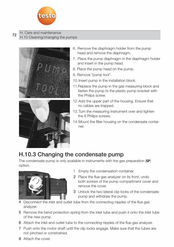
6. Remove the diaphragm holder from the pump head and remove the diaphragm.
7. Place the pump diaphragm in the diaphragm holderand insert in the pump head.
8. Place the pump head on the pump.
9. Remove “pump tool”.
10. Insert pump in the installation block.
11.Replace the pump in the gas measuring block andfasten the pump to the plastic pump bracket withthe Philips screw.
12.Add the upper part of the housing. Ensure that no cables are trapped.
13.Turn the measuring instrument over and tighten the 8 Philips screws.
14.Mount the filter housing on the condensate contai-ner.
H.10.3 Changing the condensate pumpThe condensate pump is only available in instruments with the gas preparation (GP)option.
1 Empty the condensation container.
2 Place the flue gas analyzer on its front, undo both screws of the pump compartment cover andremove the cover.
3 Unlock the two lateral clip locks of the condensatepump and withdraw the pump.
4 Disconnect the inlet and outlet tube from the connecting nipples of the flue gas analyzer.
5 Remove the bend protection spring from the inlet tube and push it onto the inlet tubeof the new pump.
6 Attach the inlet and outlet tube to the connecting nipples of the flue gas analyzer.
7 Push onto the motor shaft until the clip locks engage. Make sure that the tubes arenot pinched or constrained.
8 Attach the cover.
H. Care and maintenanceH.10 Cleaning/changing the pumps
72

H.11 Changing the filter fleece in the gascooler
The flue gas analyzer must be switched off and isolated from the mains supply.
1 Place the flue gas analyzer on its front.
2 Open the cover of the measuring cell compartment (clip lock) and remove.
3 Open the cover of the filter fleece () clockwise.
5 Replace the used filter with a new filter.
6 Close the cover.
7 Replace the cover of the sensor compartment and close.
H. Care and maintenanceH.11 Changing the filter fleece in the cooler
73

H.12 Checking flue gas analyzer forleaks
Check the flue gas analyzer for leaks at regular intervals. This will help to ensure accurate measurement.
The gas sampling probe may not be connected to the flue gas analyzer when carryingout a gas-tightness test. The gas-tightness of the gas path in the flue gas analyzer testo350-MARITIME can be tested by closing the flue gas input (see Ch. 3.3). The instrumentmust be switched on. A function key must be assigned the function Pstart (start measu-ring gas pump), see Assigning a function key, page36. A display field of themeasurement view must be assigned the parameter Pump (flue gas pump volumetricflow rate), see Changing the display sequence, see page 42.
- The measurement view is opened.
1 Close flue gas input (see Ch. 3.3.) in the flue gas analyzer ( e. g. with a thumb).
2 Press .
- Volumetric flow rate less than or equal to 0.1 l/min: measuring system is not leaking.
or-
- Volumetric flow rate greater than 0.1 l/min = measuring system is leaking.
Check the flue gas analyzer for leaks.
H.13 Recommended maintenance cyclesComponent Life Application Remedy
Measuring gas pump 1,200 h general Replace entire pumpDiluting pump 1,200 h general Replace entire pumpHose pump 2,500 h general Replace pump head with
hose 5,000 h general Replace entire pump
Fleece in gas cooler 1,200 h Fuel: gas, light fuel oil Clean the housing, replacefleece
Condensate vessel 25 ml condensate general Free draining of condensatemust be ensured
PStart
H. Care and maintenanceH.12 Checking flue gas analyzer for leaks
74

I. Questions and answersThis chapter gives answers to frequently asked questions.
Question Possible causes Remedy
Rech. battery low - Switch to mains operation.Measuring instrument keeps Batteries/ rech. batteries empty. Charge the battery or change to switching off by itself or mains operationmeasuring instrument (see Operation, page27).will not switch onNO value drifts Aux. voltage for NO measuring cell was Wait until cell is regenerated. Stable
interrupted, e.g. by change of cell NO measuring not possible until approx. 2 h after.
Double module One measuring cell of the same type -is already inserted.
Dilution Gas flow rate in dilution path too high / Please contact your dealer too low. or Testo Customer Service.
O2 cell used up - Replace O2 measuring cell.... signal too high Signal of indicated measuring cell Wait until regenerated (repeat zeroing
is too high. starts automatically).... Signal not stable Signal of indicated measuring cell Replace measuring cell.
drifts too much (faulty).... Switch-off Reading of indicated measuring cell is -
above the set switch-off threshold.Instrument temperature Instrument temperature is outside the -
operating temperaturePump volumetric flow rate Gas flow rate too low (filter clogged) or Check gas path/ filter.
gas flow rate too high (positive pressure)Gas cooling system Gas cooler not working (faulty). Please contact your dealer
or Testo Customer Service.Cell temperature O2 cell temperature outside the -too high specificationsProbe break or probe Temperature sensor not connected or Connect temperature probe ornot connected thermocouple broken replace thermocoupleAmbient air temperature No AT probe connected. The measuredstored temperature of the flue gas analyzer probe
is stored as the ambient air temperatureThe input has effects The programming relates to a memoryon values entered previously program, e.g. end criterion is invalid because
start criterion was changed.Cell no. X of sensor faulty The cell on slot no. X is faulty Contact your dealer or
and must be replaced Testo Customer Service.Check CO2 IR sensor Various Perform zeropoint calibration. If this is
no longer possible, contact your dealer or Testo Customer Service.
If we could not answer your question, please contact your dealer or Testo CustomerService. For contact details see the reverse side of this document or the web pagewww.testo.com/service-contact.
I. Questions and answers 75

J. Technical data
J.1 Checks and certificationsThe testo 350-MARITIME has the following certificate:Germanischer Lloyd (GL) certificate no. 59488 - 08 HH and DET NORSKE VERITAS(DNV)-Certificate No. A-11316 in accordance with MARPOL 73/78 Annex VI andNOx Technical Code and (MEPC.177(58)) guideline
J. Technical dataJ.1 Checks and certifications
76

J. Technical dataJ.1 Checks and certifications
77
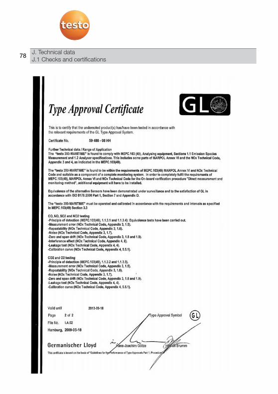
J. Technical dataJ.1 Checks and certifications
78

J. Technical dataJ.1 Checks and certifications
79

J. Technical dataJ.1 Checks and certifications
80

J. Technical dataJ.1 Checks and certifications
81

J. Technical dataJ.1 Checks and certifications
82

J. Technical dataJ.1 Checks and certifications
83

J. Technical dataJ.1 Checks and certifications
84

J. Technical dataJ.1 Checks and certifications
85

J. Technical dataJ.1 Checks and certifications
86

J. Technical dataJ.1 Checks and certifications
87

J. Technical dataJ.1 Checks and certifications
88
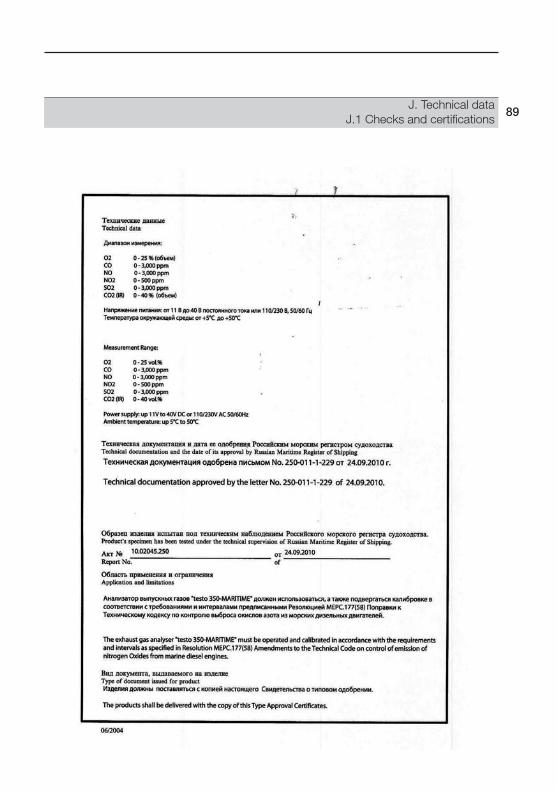
J. Technical dataJ.1 Checks and certifications
89

J.2 Measuring ranges and accuraciesParameter Measuring range Tolerance
°C, exhaust gas -40 - +1,000 °C max. ± 5 KO2 0 - 25 vol.% According to MARPOL, Annex VICO 0 - 3,000 ppm or NOx Technical CodeNO 0 - 3,000ppmNO2 0 - 500 ppmSO2 0 - 3,000 ppmCO2(IR) 0 - 40 vol.%Pabs 600 - 1,150 hPa ± 5 hPa at 22 °C
± 10 hPa at -5 - +45 °C
Parameter Measuring range Accuracy Resolution Response time1)
dP -200 - 200 hPa ±0.5 hPa (-49.9 - 49.9 hPa) 0.1 hPa -±1.5% of reading (rest of range)
Temperature -40 - 1,000 °C max. ±5 °K 0.1°C dependingon probe
Efficiency 0 - 120% - 0.1% -Flue gas loss -20.0 - 99.9% - 0.1% -
1) Recommended minimum duration of measurement to guarantee correct readings: 3 min
Testo 350-MARITIME flue gas analyzer, test gas concentrationsParameter Measuring range
CO 500 ppm (in N2)CO2 10% (in N2)NO 1,000 ppm (in N2)NO2 100 ppm (in synthetic air)SO2 1,000 ppm (in N2) (maximum)
90J. Technical dataJ.2 Measuring ranges and accuracies

J.3 Other instrument dataCharacteristic Values
Measuring system
Operating temperature +5 - +50 °CStorage/ transport temperature -10 - 50 °CHousing ABSGuarantee (according to Measuring instrument: 24 months, flue gas probe: 24 months, thermocouple: 12 months, Testo guarantee conditions) rechargeable battery: 12 months
Measuring cells: NO2 measuring cell: 12 months, O2 measuring cell: 18 months, CO2(IR) measuring cell: 24 months, CO measuring cell: 12 months or max. 275,000 ppmh filter life, NO measuring cell: 12 months or max. 70,000 ppmh filter lifeSO2 measuring cell: 12 months
testo 350-MARITIME control unit
Power supply 4x mignon AA 1.5 VBattery service life approx. 8 hDimensions (L x W x H) 252 x 115 x 58 mmWeight approx. 850 g
testo 350-MARITIME flue gas analyzer
Power supply Rechargeable battery pack (8.4 V/4.5 Ah) Integrated mains unit (90 - 260 V, 47-63 Hz, 0.3 A/230 V AC, 0.5 A/110 V AC)
Rechargeable battery charge time approx. 4-5h Dimensions (L x W x H) 395 x 275 x 95 mmWeight approx. 3,200 gMemory 250,000 readingsMax. flue gas positive pressure 50 hPaMax. underpressure 200 hPa
Pump volumetric flow rate 1.0 m/s, monitoredDiluting gas Fresh air or nitrogenMax. flue gas dust load 20 g/m3
Max. humidity load 70 °Ctd at measuring inletDew point temperature at the measuring inlet of the flue gas analyzer
91J. Technical data
J.3 Other instruments data

J.4 Recommended rinse timesRecommended rinse times for measurements involving high concentrations and measurements over long periods of time:
Rinsing the instrument: Expose the probe to fresh air and start flue gasmeasurement.
Parameter Concentration Measurement Rinse time Calibration cycles/ Filter life[ppm] period [min] [min] Month [ppm/h]
CO 50 60 05100 30 05200 20 10 3500 10 101,000 10 15 275,000 (NOx/SO2)2,000 10 20 .4,000 5 308,000 5 45 110,000 5 60
NO 50 60 05100 45 05200 30 05 3 70,000 (SO2)500 20 101,000 10 102,000 10 20 13,000 5 30
NO2 10 60 0520 45 0550 30 05 3100 20 10200 10 10500 10 20
SO2 50 60 05100 30 05200 20 10 3500 15 10 200,000 (H2S/HCI)1,000 10 102,000 10 20 15,000 05 40
92J. Technical dataJ.4 Recommended rinse times
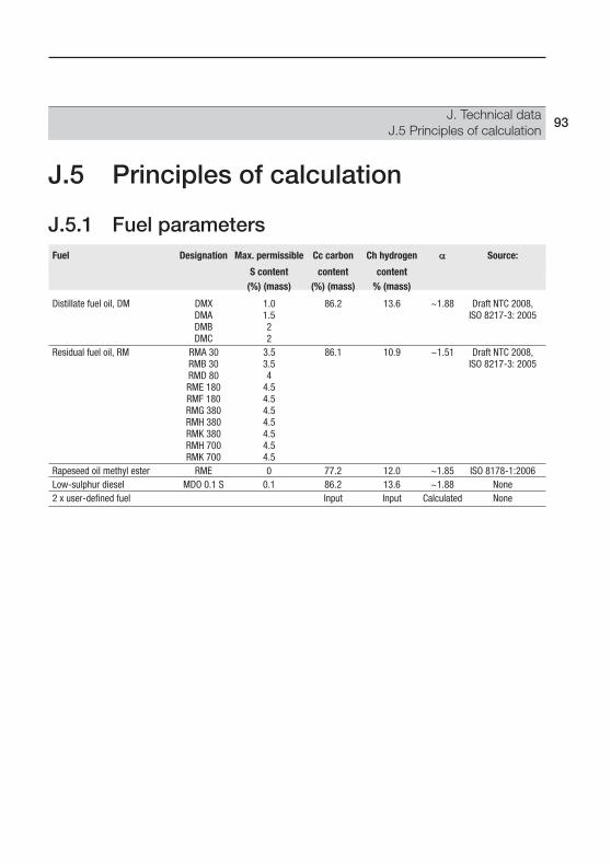
J.5 Principles of calculation
J.5.1 Fuel parametersFuel Designation Max. permissible Cc carbon Ch hydrogen Source:
S content content content(%) (mass) (%) (mass) % (mass)
Distillate fuel oil, DM DMX 1.0 86.2 13.6 ~1.88 Draft NTC 2008,DMA 1.5 ISO 8217-3: 2005DMB 2DMC 2
Residual fuel oil, RM RMA 30 3.5 86.1 10.9 ~1.51 Draft NTC 2008,RMB 30 3.5 ISO 8217-3: 2005RMD 80 4RME 180 4.5RMF 180 4.5RMG 380 4.5RMH 380 4.5RMK 380 4.5RMH 700 4.5RMK 700 4.5
Rapeseed oil methyl ester RME 0 77.2 12.0 ~1.85 ISO 8178-1:2006Low-sulphur diesel MDO 0.1 S 0.1 86.2 13.6 ~1.88 None2 x user-defined fuel Input Input Calculated None
93J. Technical data
J.5 Principles of calculation

K. Accessories/spare partsThis chapter gives important accessory and spare parts for the product.
Designation Article no.
Flue gas probes
Engine probe with filter and hose, 2.20 m 0600 7551Engine probe with filter and hose, 5 m 0600 7553Thermocouple, 2.2 m 0600 8894Thermocouple, 5 m 0600 8895Spare probe shaft with filter 0554 7455
Measuring cells (replacement)
O2 0390 0070CO 0390 0088NO 0390 0074NO2 0390 0075SO2 0390 0081
Measuring cells (for retrofitting by Service)
SO2 0554 3381
Miscellaneous
Thermal paper for printer (6 rolls) 0554 0569Rechargeable battery pack for flue gas analyzer 0554 1098Rechargeable battery pack for control unit 0554 1097Filter for flue gas analyzer, 20 pieces, yellow 0554 3381Testo databus connecting cable, 2 m 0449 0042Testo databus connecting cable, 5 m 0449 0043Testo databus connecting cable, 20 m 0449 0044Refill pack for CO2 filter granulate 0554 0369Measuring gas pump 0239 0009Pump diaphragm for measuring gas pump 0193 0049Purging and diluting pump 0239 0014Pump diaphragm for purging and diluting pump 0193 0072Cassette for hose pump cartridge 0440 0013
For a complete list of all accessories and spare parts, please refer to the product catalogues and brochures or look up our website at: www.testo.com
94 K. Accessories / spare parts

95

testo AG
Postfach 11 40, D-79849 LenzkirchTesto-Straße 1, D-79853 Lenzkirch
Telephone: +49 (0)7653-681-0Fax: +49 (0)7653-681-100
E-mail: [email protected]: http://www.testo.com
0970 3506 en 06 V02.22 en V02.06.