testing and commissioning procedure for lift · pdf filedisclaimer this t & c procedure is...
TRANSCRIPT
TESTING AND COMMISSIONING PROCEDURE
FOR
LIFT, ESCALATOR AND PASSENGER CONVEYOR
INSTALLATION
IN
GOVERNMENT BUILDINGS
OF
THE HONG KONG SPECIAL ADMINISTRATIVE REGION
2007 EDITION
ARCHITECTURAL SERVICES DEPARTMENT THE GOVERNMENT OF THE HONG KONG SPECIAL ADMINISTRATIVE REGION
PREFACE This Testing and Commissioning (T & C) Procedure aims to lay down the minimum testing and commissioning requirements to be carried out on lift, escalator and passenger conveyor installation in Government Buildings of the Hong Kong Special Administrative Region (HKSAR). Such requirements are applicable to both new installations upon completion and existing ones after major alteration. The present edition was developed based on its 2000 edition by the Lift and Escalator Specialist Support Group that was established under the Building Services Branch Technical Information and Research & Development Committee. With the benefit of information technology, electronic version of this new edition is to be viewed on and free for download from the Architectural Services Department (ArchSD) Internet homepage. As part of the Government’s efforts to limit paper consumption, hard copies of this T & C Procedure will not be put up for sale. The Architectural Services Department welcomes comments on its contents at anytime since the updating of this T & C Procedure is a continuous process to tie in with technological advances.
DISCLAIMER This T & C Procedure is solely compiled for use on lift, escalator and passenger conveyor installation carried out for or on behalf of the ArchSD in Government buildings of the HKSAR. There are no representations, either expressed or implied, as to the suitability of this T & C Procedure for purposes other than that stated above. The material contained in this T & C Procedure may not be pertinent or fully cover the extent of the installation in non-government buildings. Users who choose to adopt this T & C Procedure for their works are responsible for making their own assessments and judgement of all information contained here. The Architectural Services Department does not accept any liability and responsibility for any special, indirect or consequential loss or damage whatsoever arising out of or in connection with the use of this T & C Procedure or reliance placed on it.
Table of Contents Page 1 of 2
LF_TCP 2007 Edition
TABLE OF CONTENTS
1. Introduction 2. Objectives of the T & C Works 3. Scope of the T & C Works
3.1 Tests and Inspections during Installation 3.2 Functional Performance Tests 3.3 Commissioning and Statutory Inspections 3.4 Documentation and Deliverables
4. T & C Procedures
4.1 Tests and Inspections during Installation 4.1.1 Lift Installation 4.1.2 Escalator and Passenger Conveyor Installation 4.1.3 Vertical Lifting Platform Installation 4.1.4 Stairlift Installation
4.2 Functional Performance Tests 4.2.1 Lift Installation 4.2.2 Escalator and Passenger Conveyor Installation 4.2.3 Vertical Lifting Platform Installation 4.2.4 Stairlift Installation
4.3 Commissioning and Statutory Inspections
4.3.1 Lift Installation 4.3.2 Escalator and Passenger Conveyor Installation 4.3.3 Vertical Lifting Platform Installation 4.3.4 Stairlift Installation

Table of Contents Page 2 of 2
LF_TCP 2007 Edition
Appendices Appendix A Testing and Commissioning Certificate on Lift Installation Appendix B Testing and Commissioning Certificate on Escalator/
Passenger Conveyor Installation Appendix C Testing and Commissioning Certificate on Vertical Lifting
Platform Installation Appendix D Testing and Commissioning Certificate on Stairlift
Installation Annexes Annex A Test and Examination Report for Electric Passenger Lifts
/Freight Lifts/Non-commercial Vehicle Lifts Annex B Test and Examination Report for Hydraulic Passenger Lifts
/Freight Lifts/Non-commercial Vehicle Lifts Annex C Test and Examination Report for Escalators/Passenger
Conveyors Annex D Test and Examination Report for Electric Service Lifts Annex E Testing and Commissioning Progress Chart for Lift, Escalator,
Passenger Conveyor, Vertical Lifting Platform and Stairlift Installation
Annex F List of Calibrated Instrument Necessary for the Testing and
Commissioning Works
Page 1 of 9
LF_TCP 2007 Edition
Testing and Commissioning Procedure Lift, Escalator and Passenger Conveyor Installation
1. Introduction
The procedures stated in this document cover the activities in preliminary tests and inspections, functional performance tests and the commissioning of newly completed installations and existing ones after major alteration. They are so compiled to facilitate the work of Project Building Services Engineer (PBSE) and Project Building Services Inspector (PBSI) in the following aspects with respect to testing and commissioning (T&C): (i) To vet and approve the T&C procedures proposed and submitted
by the Contractor; (ii) To witness those T&C procedures as specified; and (iii) To accept the T&C certificates and other supporting data. The Contractor shall carry out the T & C works as detailed in this document. Supplementary T&C plans may be proposed by the Contractor as appropriate and agreed by PBSE, e.g. for special equipment supplied and/or installed by the Contractor. The administrative requirements for T & C works are in general as specified in the latest General Specification for Lift, Escalator and Passenger Conveyor Installation (the General Specification) issued by the Building Services Branch of the Architectural Services Department. If there is any discrepancy between this procedure and the General Specification, the General Specification shall take precedence.
2. Objectives of the T & C works
The objectives of the T & C works are: (i) to verify proper functioning of the equipment/system after
installation; (ii) to verify that the performance of the installed equipment/systems
meet with the specified design intent through a series of tests and adjustments; and
(iii) to capture and record performance data of the whole installation
as the baseline for future operation and maintenance.
All the test results shall be recorded by the Contractor in the appropriate test record forms, the reference of which is shown against each individual test. A complete set of these forms is included in the relevant appendices and annexes of this Procedure.

Page 2 of 9
LF_TCP 2007 Edition
3. Scope of the T & C Works
3.1 Tests and Inspections during Installation The purpose of these tests is to ensure that all components and
systems are in a satisfactory and safe condition before start up. Prior to the installation, certain tests and inspections shall be carried out to ensure that proper materials and equipment complying with the specification are provided and that the site conditions are satisfactory and suitable for the execution of the installation. Preliminary adjustment and setting of equipment at this stage shall also be carried out at the same time to pave way for the coming functional performance tests.
Before carrying out any test, the Contractor shall ensure that the
installation complies with all relevant statutory requirements and regulations. The T&C works shall also comply with all site safety regulatory requirements currently in force namely:
(i) Lifts and Escalators (Safety) Ordinance (ii) Electricity Ordinance, Chapter 406, and other subsidiary
legislations (iii) Code of Practice on the Design and Construction of Lifts
and Escalators issued by Electrical and Mechanical Services Department, Government of The Hong Kong Special Administrative Region.
(iv) Code of Practice for Lift Works and Escalator Works issued by Electrical and Mechanical Services Department, Government of The Hong Kong Special Administrative Region
(v) Code of Practice on the Design and Construction of Buildings and Building Works for the Installation and Safe Use of Lifts and Escalators issued by Building Authority, Government of The Hong Kong Special Administrative Region.
(vi) Code of Practice for Safety at Work (Lift & Escalator) issued by Labour Department, Government of The Hong Kong Special Administrative Region.
(vii) The latest Code of Practice for the Electricity (Wiring) Regulations
(viii) ISO 9386-1:2000, ‘Power-operated lifting platforms for persons with impaired mobility – Rules for safety, dimensions and functional operation – Part 1 : Vertical lifting platforms;
(ix) BS6440:1999, ‘Powered Lifting Platforms for Use by Disabled Persons’
(x) ASME A18.1:2005, “Safety Standard for Platform Lifts and Stairway Chairlifts
(xi) Code of Practice for Minimum Fire Service Installations and Equipment and Inspection, Testing and Maintenance of Installations and Equipment issued by the Fire Services Department of The Hong Kong Special Administrative Region
Page 3 of 9
LF_TCP 2007 Edition
(xii) Code of Practice for Energy Efficiency of Lift and Escalator Installations issued by Electrical and Mechanical Services Department of The Hong Kong Special Administrative Region
(xiii) Relevant National/International Standards and Codes of Practice
3.2 Functional Performance Tests
The purpose of functional performance tests is to demonstrate
that the equipment/installation can meet the functional and performance requirements as specified in the General/Particular Specifications. Functional performance test should proceed from the testing of individual components to the testing of different systems in the installation.
The Contractor may have to make temporary modifications as
the test proceeds. The specific tests required and the order of tests will vary depending on the type and size of systems, number of systems, sequence of construction, interface with other installations, relationship with the building elements and other specific requirements as indicated in the General/Particular Specifications. The testing of systems may have to be carried out in stages depending on the progress of work or as proposed by the Contractor.
Part of the tests may be required to be carried out in suppliers’
premises in accordance with the provisions in the General/Particular Specification.
Any performance deficiencies revealed during the functional
performance tests must be evaluated to determine the cause and whether they are part of the contractual obligations. After completion of the necessary corrective measures, the Contractor shall repeat the tests.
If any test cannot be completed because of circumstances that
are beyond the control of the Contractor, it shall be properly documented and reported to the PBSE, who shall then liaise with the relevant parties to resolve the situation. The Contractor shall resume his testing work immediately upon the attainment of a suitable testing environment.
3.3 Commissioning and Statutory Inspections Commissioning is the advancement of an installation from the
stage of static completion to full working conditions and to meet the performance requirements as specified in the General/Particular Specification. This will include setting into operation and regulation of the installation. It is expected that fine-tuning of the commissioned system shall be done by the Contractor to match system performance to the actual needs of
Page 4 of 9
LF_TCP 2007 Edition
the building occupier more closely. Where necessary, after the proper testing and commissioning of
the Lift, Escalator, Passenger Conveyor, Vertical Lifting Platform and Stairlift Installation, the Contractor shall notify the appropriate authority, through the PBSE of the completion of the installation and its readiness for final inspection.
3.4 Documentation and Deliverables
The Contractor shall submit his proposed T & C procedures
together with the Testing and Commissioning Progress Chart shown in Annex E to PBSE for approval.
All inspection and T & C results shall be recorded in the data
record forms shown in the relevant appendices and annexes of this Procedure. Data recorded in other formats may also acceptable subject to agreement between the PBSE and the Contractor. Upon completion of all the required T&C works, the Contractor’s project engineer shall complete and sign the testing and commissioning certificates as shown in the relevant appendices and the certification on test and examination as shown in relevant annexes to the effect that the agreed T & C works have been duly carried out.
A functional performance test report covering all measured data,
data sheets, and a comprehensive summary describing the operation of the system at the time of the functional performance tests shall be prepared and submitted to the PBSE. Deviations in performance from the General/Particular Specifications or the design intent should be recorded, with a description and analysis included.
Where required in the General Specification, the Contractor
shall conduct a final evaluation of the performance of the Lift, Escalator, Passenger Conveyor, Vertical Lifting Platform and Stairlift Installation, the results of which shall be included in the commissioning report.
4. T & C Procedures
4.1 Tests and Inspections during Installation Certain tests will be carried out on different systems of the
installation during construction to ensure their suitability for operating at the design conditions. Prior to the installation, certain tests and inspections shall also be carried out to ensure that proper materials and equipment complying with the specification are provided and that the site conditions are satisfactory and suitable for the execution of the installation. Certificates of such tests have to be issued together with certificates of any work tests.

Page 5 of 9
LF_TCP 2007 Edition
Relevant Clauses
4.1.1 Lift Installation A. Tests/Inspections to be carried out before installation (a) Factory Tests and Off-site Tests (b) Site Inspection prior to Delivery of Equipment
(i) Access (ii) Barrier (iii) Lighting (iv) Storage of Equipment
(c) Inspection of Major Materials/Equipment delivered to site (i) Check against approved lists (ii) Check for any abnormalities
(d) Lift Shaft and Lift Pit Inspection (i) Dimensions (ii) Finishes (iii) Adequacy and accuracy of builder’s work
provision (iv) Straightness of shaft (v) Adequacy of safety measures
(e) Machine Room Inspection (i) Dimensions (ii) Finishes (iii) Adequacy and accuracy of builder’s work
provision (iv) Adequacy and accuracy of building services
provisions (v) Adequacy of waterproofing/drainage
provisions (vi) Adequacy of safety measures
(f) Adequacy and accuracy of associated builder’s work and building services provisions such as door opening, opening on machine room floor, hoisting provision, power supply and cabling facilities etc
(g) Other tests/inspections relating to setting-outs, safety and quality etc required before commencing installation works
B. Tests/Inspections to be carried out during installation (i) Guide rails and fixing inside lift shaft (ii) Guide shoes (iii) Suspension rope termination including
compensating chain/rope (iv) Overspeed governor (v) Buffer (vi) Electrical installation in lift shaft (vii) Electrical installation in machine room (viii) Inspections required before energisation
Clause 3.2 of Appendix A Clause 3.3 of Appendix A
Page 6 of 9
LF_TCP 2007 Edition
4.1.2 Escalator and Passenger Conveyor Installation A. Tests/Inspections to be carried out before installation (a) Factory Tests and Off-site Tests (b) Site Inspection prior to Delivery of Equipment
(i) Access (ii) Barrier (iii) Lighting (iv) Storage of Equipment
(c) Inspection of Major Materials/Equipment delivered to site
(i) Check against approved lists (ii) Check for any abnormalities
(d) Escalator Pit Inspection (i) Dimension (ii) Finishes (iii) Adequacy and accuracy of builder’s work
provision (e) Adequacy and accuracy of associated builder’s work
and building services provisions (f) Other tests/inspections relating to setting-outs, safety
and quality etc required before commencing installation works
B. Tests/Inspections to be carried out during installation
(i) Steps/Pallets (ii) Combs (iii) Balustrades (iv) Handrails (v) Driving Machinery and Braking (vi) Footlight and Step Lights (vii) Safety Device (viii) Control Station (ix) Controller (x) Maintenance Facilities (xi) Electrical installation in escalator pit (xii) Provisions for weatherproof/outdoor escalator (xiii) Other Inspection required before energisation
Clause 3.2 of Appendix B Clause 3.3 of Appendix B
4.1.3 Vertical Lifting Platform Installation A. Tests/Inspections to be carried out before installation (a) Factory Tests and Off-site Tests (b) Site Inspection prior to Delivery of Equipment
(i) Access (ii) Barrier (iii) Lighting (iv) Storage of Equipment
(c) Inspection of Major Materials/Equipment delivered to site
Clause 3.2 of Appendix C

Page 7 of 9
LF_TCP 2007 Edition
(i) Check against approved lists (ii) Check for any abnormalities
(d) Vertical Lift Pit/Ramp and Concrete Wall Inspection (i) Dimension (ii) Finishes (iii) Adequacy and accuracy of builder’s work
provision (e) Adequacy and accuracy of associated builder’s work and building services provisions (f) Other tests/inspections relating to setting-outs, safety and quality etc required before commencing installation works
B. Tests/Inspections to be carried out during installation
(i) Drive system (ii) Liftway enclosure lighting (iii) Platform (iv) Landing door/gate (v) Operation control system (vi) Safety device (vii) Call bell system (viii) Supervisory control panel (ix) Intercom system (x) Close circuit television (xi) Electrical installation in vertical lift pit (xii) Provisions for weatherproof/outdoor vertical
lifting platform (xiii) Other inspection required before energisation
4.1.4 Stairlift Installation
A. Tests/Inspections to be carried out before installation (a) Factory Tests and Off-site Tests (b) Site Inspection prior to Delivery of Equipment
(i) Access (ii) Barrier (iii) Lighting and Power (iv) Storage area
(c) Inspection of Major Materials/Equipment delivered to site
(i) Check against approved lists (ii) Check for any abnormalities
(d) Structural members of building for mounting of stairlift installation
(e) Stairlift railing (f) Adequacy and accuracy of associated builder’s work
and building services provisions (g) Other tests/inspections relating to setting-outs, safety and quality etc required before commencing installation works
Clause 3.3 of Appendix D
Page 8 of 9
LF_TCP 2007 Edition
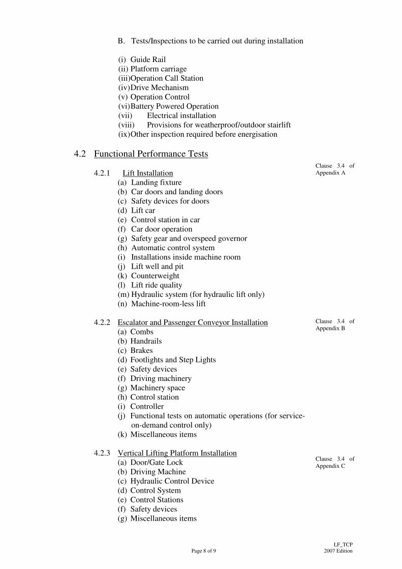
B. Tests/Inspections to be carried out during installation
(i) Guide Rail (ii) Platform carriage (iii)Operation Call Station (iv) Drive Mechanism (v) Operation Control (vi) Battery Powered Operation (vii) Electrical installation (viii) Provisions for weatherproof/outdoor stairlift (ix) Other inspection required before energisation
4.2 Functional Performance Tests
4.2.1 Lift Installation
(a) Landing fixture (b) Car doors and landing doors (c) Safety devices for doors (d) Lift car (e) Control station in car (f) Car door operation (g) Safety gear and overspeed governor (h) Automatic control system (i) Installations inside machine room (j) Lift well and pit (k) Counterweight (l) Lift ride quality (m) Hydraulic system (for hydraulic lift only) (n) Machine-room-less lift
Clause 3.4 of Appendix A
4.2.2 Escalator and Passenger Conveyor Installation (a) Combs (b) Handrails (c) Brakes (d) Footlights and Step Lights (e) Safety devices (f) Driving machinery (g) Machinery space (h) Control station (i) Controller (j) Functional tests on automatic operations (for service-
on-demand control only) (k) Miscellaneous items
Clause 3.4 of Appendix B
4.2.3 Vertical Lifting Platform Installation (a) Door/Gate Lock (b) Driving Machine (c) Hydraulic Control Device (d) Control System (e) Control Stations (f) Safety devices (g) Miscellaneous items
Clause 3.4 of Appendix C

Page 9 of 9
LF_TCP 2007 Edition
4.2.4 Stairlift Installation (a) General Operation (b) Drive System (c) Platform Carriage (d) Operation Control (e) Miscellaneous items
Clause 3.4 of Appendix D
4.3 Commissioning and Statutory Inspections 4.3.1 Lift Installation
(a) Static Examination - Mechanical (b) Static Examination – Electrical (c) Dynamic Tests (d) Electrical System (e) Hydraulic System (for hydraulic lift only) (f) Governor/Safety Ropes/Suspension Gear Tests (g) Car Safety Gear Tests (h) Counterweight Safety Gear Test (i) Clamping Device Tests (for hydraulic lift only) (j) Buffer Tests (k) Anti-creep (for hydraulic lift only) (l) Traction Check (m) Duty Cycle Test (n) General (o) Other tests, inspections and examination as required
Clause 3.5 of Appendix A Annex A or Annex B (for hydraulic lift) or Annex D (for service lift)
4.3.2 Escalator and Passenger Conveyor Installation (a) Static Examination (b) Dynamic Tests (c) Electrical System (d) Clearance (e) Half-hour Run (f) General (g) Other tests, inspections and examination as required
Clause 3.5 of Appendix B Annex C
4.3.3 Vertical Lifting Platform Installation (a) Half Hour Run (b) Other tests, inspections and examination as required
Clause 3.5 of Appendix C
4.4.4 Stairlift Installation (a) Half Hour Run (b) Other tests, inspections and examination as required
Clause 3.5 of Appendix D
Appendix A
Architectural Services Department Appendix A Issue Date: 17 Dec 2007 BSB– Standard Form No:PBS/SR.064(2007) Page 1 of 34 Revision Date: - LF_TCP (2007 Edition)
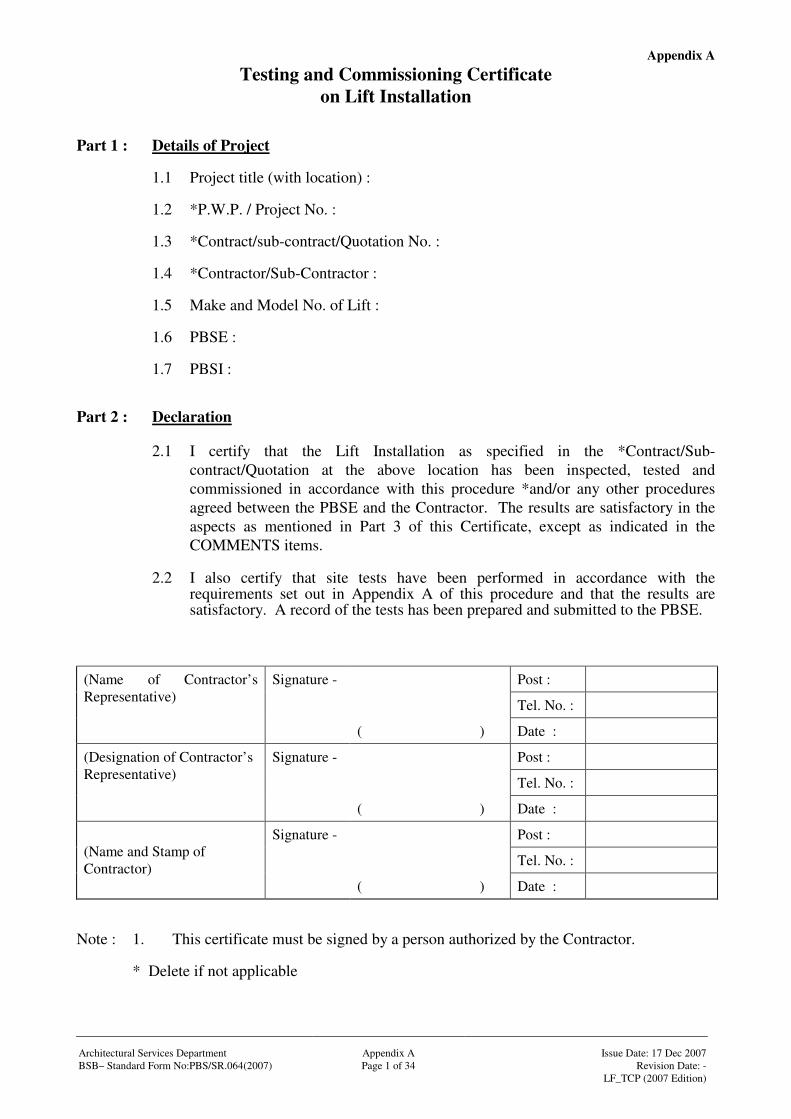
Testing and Commissioning Certificate on Lift Installation
Part 1 : Details of Project
1.1 Project title (with location) : 1.2 *P.W.P. / Project No. : 1.3 *Contract/sub-contract/Quotation No. : 1.4 *Contractor/Sub-Contractor : 1.5 Make and Model No. of Lift : 1.6 PBSE : 1.7 PBSI :
Part 2 : Declaration
2.1 I certify that the Lift Installation as specified in the *Contract/Sub-contract/Quotation at the above location has been inspected, tested and commissioned in accordance with this procedure *and/or any other procedures agreed between the PBSE and the Contractor. The results are satisfactory in the aspects as mentioned in Part 3 of this Certificate, except as indicated in the COMMENTS items.
2.2 I also certify that site tests have been performed in accordance with the
requirements set out in Appendix A of this procedure and that the results are satisfactory. A record of the tests has been prepared and submitted to the PBSE.
Signature - Post :
Tel. No. :
(Name of Contractor’s Representative)
( ) Date :
Signature - Post :
Tel. No. :
(Designation of Contractor’s Representative)
( ) Date :
Signature - Post :
Tel. No. : (Name and Stamp of Contractor)
( ) Date : Note : 1. This certificate must be signed by a person authorized by the Contractor. * Delete if not applicable
Appendix A
Signature - Post :
Tel. No. :
Tested / Checked by : (Name of Contractor’s Representative)
( ) Date :
Signature - Post :
Tel. No. :
Witnessed by : (Name(s) of *PBSE/PBSI)
( ) Date : Architectural Services Department Appendix A Issue Date: 17 Dec 2007 BSB– Standard Form No:PBS/SR.064(2007) Page 2 of 34 Revision Date: - LF_TCP (2007 Edition)
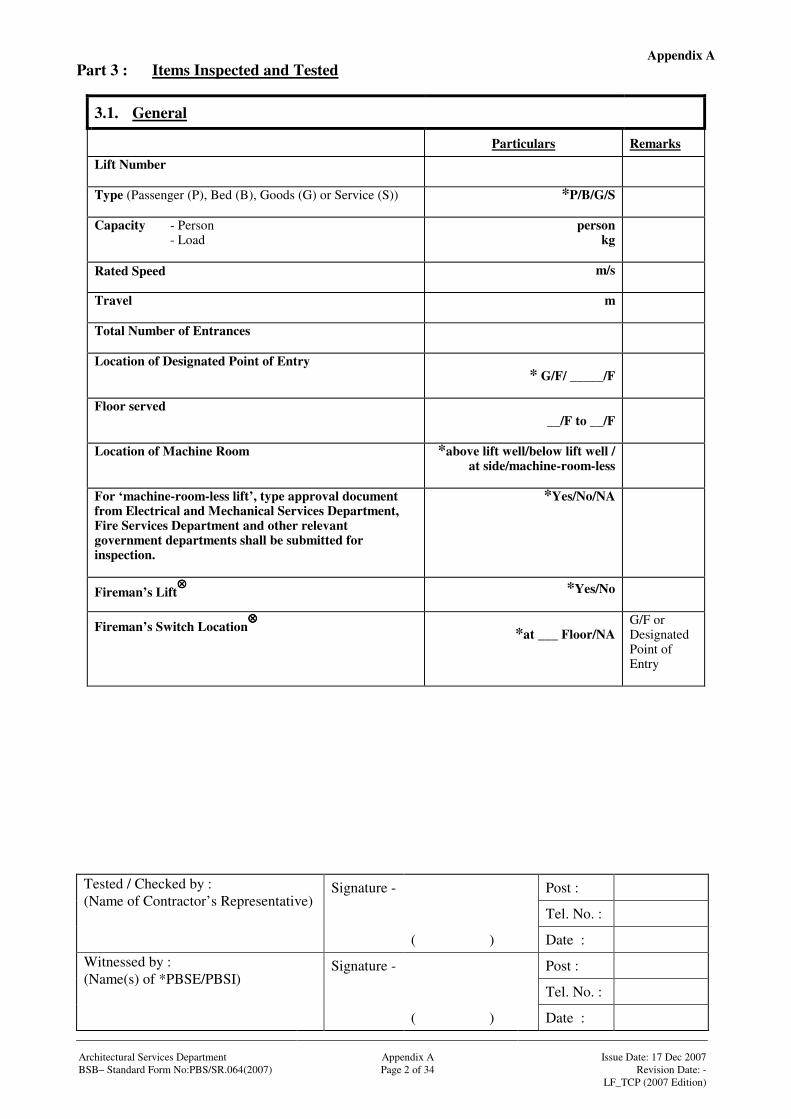
Part 3 : Items Inspected and Tested
3.1. General
Particulars Remarks Lift Number
Type (Passenger (P), Bed (B), Goods (G) or Service (S)) *P/B/G/S
Capacity - Person - Load
person kg
Rated Speed m/s
Travel m
Total Number of Entrances
Location of Designated Point of Entry * G/F/ _____/F
Floor served __/F to __/F
Location of Machine Room *above lift well/below lift well / at side/machine-room-less
For ‘machine-room-less lift’, type approval document from Electrical and Mechanical Services Department, Fire Services Department and other relevant government departments shall be submitted for inspection.
*Yes/No/NA
Fireman’s Lift⊗⊗⊗⊗ *Yes/No
Fireman’s Switch Location⊗⊗⊗⊗
*at ___ Floor/NA
G/F or Designated Point of Entry
Appendix A
Signature - Post :
Tel. No. :
Tested / Checked by : (Name of Contractor’s Representative)
( ) Date :
Signature - Post :
Tel. No. :
Witnessed by : (Name(s) of *PBSE/PBSI)
( ) Date : Architectural Services Department Appendix A Issue Date: 17 Dec 2007 BSB– Standard Form No:PBS/SR.064(2007) Page 3 of 34 Revision Date: - LF_TCP (2007 Edition)
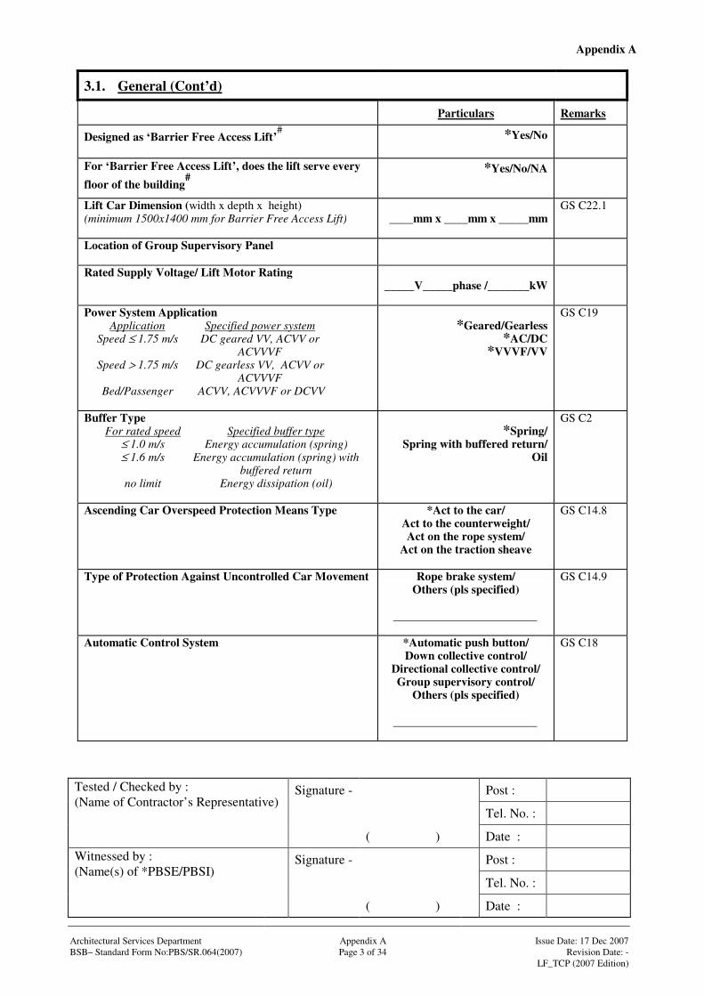
3.1. General (Cont’d)
Particulars Remarks
Designed as ‘Barrier Free Access Lift’#
*Yes/No
For ‘Barrier Free Access Lift’, does the lift serve every floor of the building
#
*Yes/No/NA
Lift Car Dimension (width x depth x height) (minimum 1500x1400 mm for Barrier Free Access Lift)
____mm x ____mm x _____mm
GS C22.1
Location of Group Supervisory Panel
Rated Supply Voltage/ Lift Motor Rating _____V_____phase /_______kW
Power System Application Application Specified power system Speed ≤ 1.75 m/s DC geared VV, ACVV or ACVVVF Speed > 1.75 m/s DC gearless VV, ACVV or ACVVVF Bed/Passenger ACVV, ACVVVF or DCVV
*Geared/Gearless
*AC/DC *VVVF/VV
GS C19
Buffer Type For rated speed Specified buffer type ≤ 1.0 m/s Energy accumulation (spring) ≤ 1.6 m/s Energy accumulation (spring) with buffered return no limit Energy dissipation (oil)
*Spring/
Spring with buffered return/ Oil
GS C2
Ascending Car Overspeed Protection Means Type *Act to the car/ Act to the counterweight/ Act on the rope system/
Act on the traction sheave
GS C14.8
Type of Protection Against Uncontrolled Car Movement Rope brake system/ Others (pls specified)
GS C14.9
Automatic Control System *Automatic push button/ Down collective control/
Directional collective control/ Group supervisory control/
Others (pls specified)
GS C18
Appendix A
Signature - Post :
Tel. No. :
Tested / Checked by : (Name of Contractor’s Representative)
( ) Date :
Signature - Post :
Tel. No. :
Witnessed by : (Name(s) of *PBSE/PBSI)
( ) Date : Architectural Services Department Appendix A Issue Date: 17 Dec 2007 BSB– Standard Form No:PBS/SR.064(2007) Page 4 of 34 Revision Date: - LF_TCP (2007 Edition)
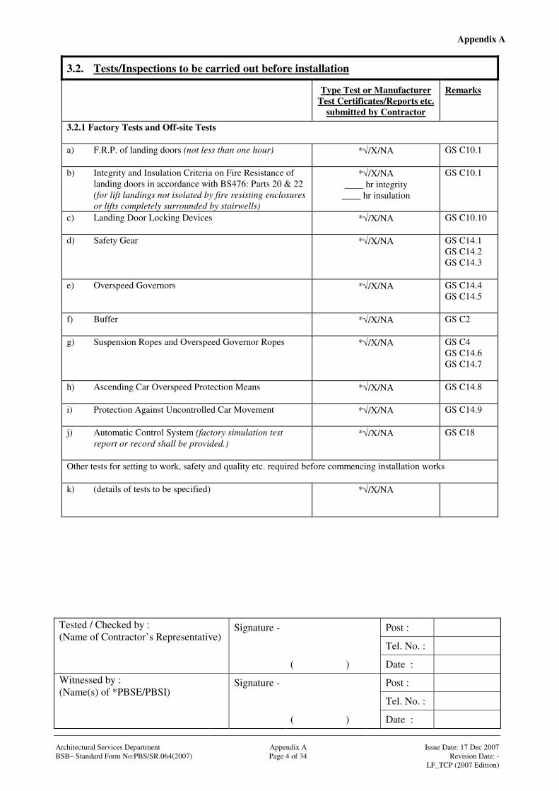
3.2. Tests/Inspections to be carried out before installation
Type Test or Manufacturer Test Certificates/Reports etc.
submitted by Contractor
Remarks
3.2.1 Factory Tests and Off-site Tests a) F.R.P. of landing doors (not less than one hour)
*√/X/NA GS C10.1
b) Integrity and Insulation Criteria on Fire Resistance of landing doors in accordance with BS476: Parts 20 & 22 (for lift landings not isolated by fire resisting enclosures or lifts completely surrounded by stairwells)
*√/X/NA ____ hr integrity
____ hr insulation
GS C10.1
c) Landing Door Locking Devices
*√/X/NA GS C10.10
d) Safety Gear
*√/X/NA GS C14.1 GS C14.2 GS C14.3
e) Overspeed Governors
*√/X/NA GS C14.4 GS C14.5
f) Buffer
*√/X/NA GS C2
g) Suspension Ropes and Overspeed Governor Ropes
*√/X/NA GS C4 GS C14.6 GS C14.7
h) Ascending Car Overspeed Protection Means
*√/X/NA GS C14.8
i) Protection Against Uncontrolled Car Movement
*√/X/NA GS C14.9
j) Automatic Control System (factory simulation test report or record shall be provided.)
*√/X/NA GS C18
Other tests for setting to work, safety and quality etc. required before commencing installation works k) (details of tests to be specified)
*√/X/NA
Appendix A
Signature - Post :
Tel. No. :
Tested / Checked by : (Name of Contractor’s Representative)
( ) Date :
Signature - Post :
Tel. No. :
Witnessed by : (Name(s) of *PBSE/PBSI)
( ) Date : Architectural Services Department Appendix A Issue Date: 17 Dec 2007 BSB– Standard Form No:PBS/SR.064(2007) Page 5 of 34 Revision Date: - LF_TCP (2007 Edition)
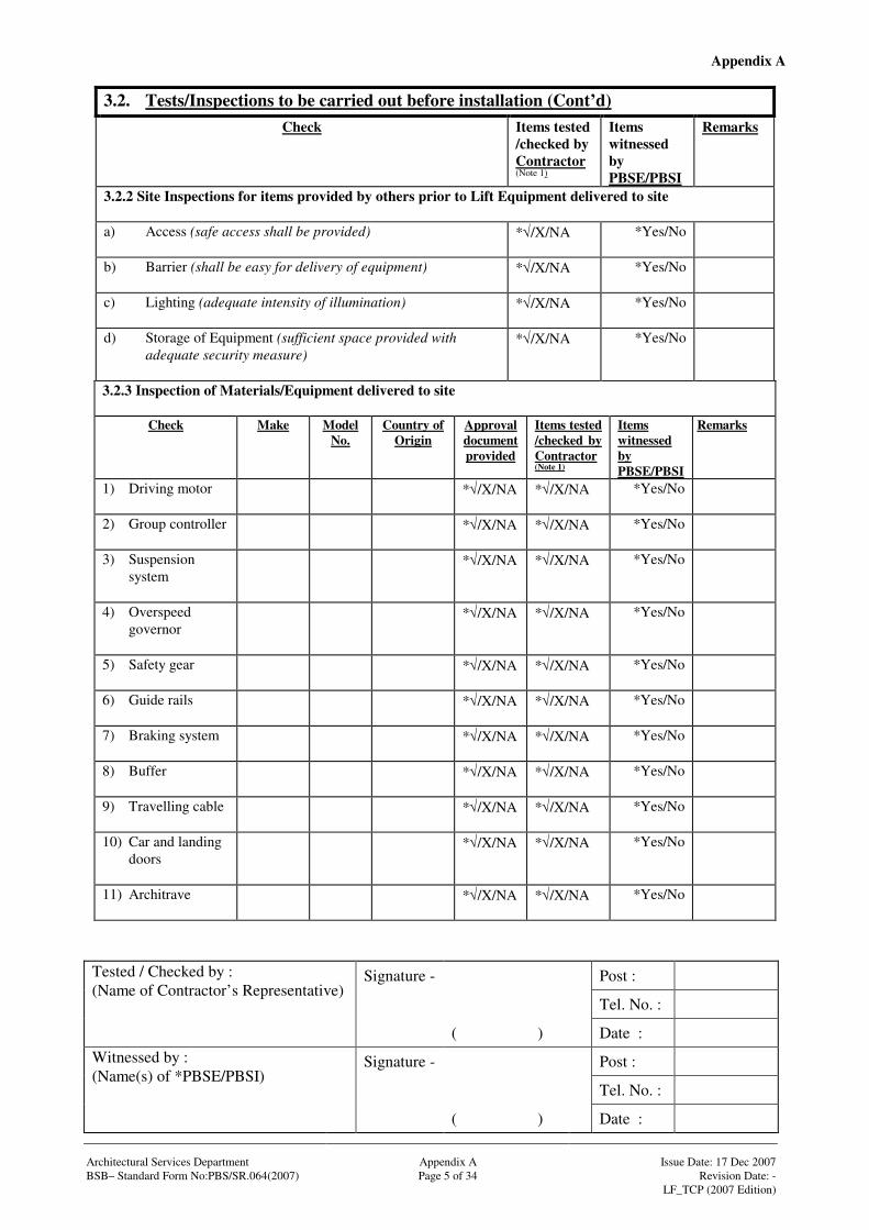
3.2. Tests/Inspections to be carried out before installation (Cont’d)
Check Items tested /checked by Contractor (Note 1)
Items witnessed by PBSE/PBSI
Remarks
3.2.2 Site Inspections for items provided by others prior to Lift Equipment delivered to site a) Access (safe access shall be provided)
*√/X/NA *Yes/No
b) Barrier (shall be easy for delivery of equipment)
*√/X/NA *Yes/No
c) Lighting (adequate intensity of illumination)
*√/X/NA *Yes/No
d) Storage of Equipment (sufficient space provided with adequate security measure)
*√/X/NA *Yes/No
3.2.3 Inspection of Materials/Equipment delivered to site
Check Make Model No.
Country of Origin
Approval document provided
Items tested /checked by Contractor (Note 1)
Items witnessed by PBSE/PBSI
Remarks
1) Driving motor
*√/X/NA *√/X/NA *Yes/No
2) Group controller
*√/X/NA *√/X/NA *Yes/No
3) Suspension system
*√/X/NA *√/X/NA *Yes/No
4) Overspeed governor
*√/X/NA *√/X/NA *Yes/No
5) Safety gear
*√/X/NA *√/X/NA *Yes/No
6) Guide rails
*√/X/NA *√/X/NA *Yes/No
7) Braking system
*√/X/NA *√/X/NA *Yes/No
8) Buffer
*√/X/NA *√/X/NA *Yes/No
9) Travelling cable
*√/X/NA *√/X/NA *Yes/No
10) Car and landing doors
*√/X/NA *√/X/NA *Yes/No
11) Architrave
*√/X/NA *√/X/NA *Yes/No

Appendix A
Signature - Post :
Tel. No. :
Tested / Checked by : (Name of Contractor’s Representative)
( ) Date :
Signature - Post :
Tel. No. :
Witnessed by : (Name(s) of *PBSE/PBSI)
( ) Date : Architectural Services Department Appendix A Issue Date: 17 Dec 2007 BSB– Standard Form No:PBS/SR.064(2007) Page 6 of 34 Revision Date: - LF_TCP (2007 Edition)
3.2. Tests/Inspections to be carried out before installation (Cont’d) Check Make Model
No. Country of
Origin Approval document provided
Items tested /checked by Contractor (Note 1)
Items witnessed by PBSE/PBSI
Remarks
3.2.3 Inspection of Materials/Equipment delivered to site (Cont’d) 12) Indicators
(position, direction and message)
*√/X/NA *√/X/NA *Yes/No
13) Information Display System monitor
*√/X/NA *√/X/NA *Yes/No
14) Information Display System audio & video equipment
*√/X/NA *√/X/NA *Yes/No
15) Intercom facilities
*√/X/NA *√/X/NA *Yes/No
16) Voice Announciator
*√/X/NA *√/X/NA *Yes/No
17) CCTV system
*√/X/NA *√/X/NA *Yes/No
18) Hydraulic Unit(for hydraulic lift only)
*√/X/NA *√/X/NA *Yes/No
19) Hydraulic oil cooler (for hydraulic lift only)
*√/X/NA *√/X/NA *Yes/No
20) Hydraulic oil heater (for hydraulic lift only)
*√/X/NA *√/X/NA *Yes/No
21) Others (pls provide details)
*√/X/NA *√/X/NA *Yes/No

Appendix A
Signature - Post :
Tel. No. :
Tested / Checked by : (Name of Contractor’s Representative)
( ) Date :
Signature - Post :
Tel. No. :
Witnessed by : (Name(s) of *PBSE/PBSI)
( ) Date : Architectural Services Department Appendix A Issue Date: 17 Dec 2007 BSB– Standard Form No:PBS/SR.064(2007) Page 7 of 34 Revision Date: - LF_TCP (2007 Edition)
3.2. Tests/Inspections to be carried out before installation (Cont’d)
Check Items tested /checked by Contractor (Note1)
Items witnessed by PBSE/PBSI
Remarks
3.2.4 Machine Room (provisions by others): a) Dimensions
*√/X/NA *Yes/No
b) Wall, floor and ceiling finishes
*√/X/NA *Yes/No
c) Adequacy of waterproofing/drainage provisions
*√/X/NA *Yes/No
d) Ventilation openings provided and protected against rain
*√/X/NA *Yes/No
e) Adequacy and accuracy of other builder’s work provisions (such as door opening, floor openings, hoisting provision, etc.)
*√/X/NA *Yes/No
f) Adequacy and accuracy of building services provisions (such as lighting points, power supply and cabling facilities etc.)
*√/X/NA *Yes/No GS B2.1 GS B2.2
Appendix A
Signature - Post :
Tel. No. :
Tested / Checked by : (Name of Contractor’s Representative)
( ) Date :
Signature - Post :
Tel. No. :
Witnessed by : (Name(s) of *PBSE/PBSI)
( ) Date : Architectural Services Department Appendix A Issue Date: 17 Dec 2007 BSB– Standard Form No:PBS/SR.064(2007) Page 8 of 34 Revision Date: - LF_TCP (2007 Edition)
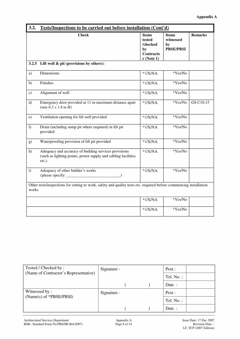
3.2. Tests/Inspections to be carried out before installation (Cont’d) Check Items
tested /checked by Contractor (Note 1)
Items witnessed by PBSE/PBSI
Remarks
3.2.5 Lift well & pit (provisions by others): a) Dimensions
*√/X/NA *Yes/No
b) Finishes
*√/X/NA *Yes/No
c) Alignment of well
*√/X/NA *Yes/No
d) Emergency door provided at 11 m maximum distance apart (min 0.5 x 1.8 m H)
*√/X/NA *Yes/No GS C10.15
e) Ventilation opening for lift well provided
*√/X/NA
*Yes/No
f) Drain (including sump pit where required) in lift pit provided
*√/X/NA
*Yes/No
g) Waterproofing provision of lift pit provided
*√/X/NA *Yes/No
h) Adequacy and accuracy of building services provisions (such as lighting points, power supply and cabling facilities etc.)
*√/X/NA *Yes/No
i) Adequacy of other builder’s works (please specify: )
*√/X/NA *Yes/No
Other tests/inspections for setting to work, safety and quality tests etc. required before commencing installation works
*√/X/NA *Yes/No
*√/X/NA *Yes/No
Appendix A
Signature - Post :
Tel. No. :
Tested / Checked by : (Name of Contractor’s Representative)
( ) Date :
Signature - Post :
Tel. No. :
Witnessed by : (Name(s) of *PBSE/PBSI)
( ) Date : Architectural Services Department Appendix A Issue Date: 17 Dec 2007 BSB– Standard Form No:PBS/SR.064(2007) Page 9 of 34 Revision Date: - LF_TCP (2007 Edition)
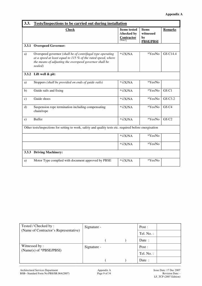
3.3. Tests/Inspections to be carried out during installation
Check Items tested /checked by Contractor (Note1)
Items witnessed by PBSE/PBSI
Remarks
3.3.1 Overspeed Governor: a) Overspeed governor (shall be of centrifugal type operating
at a speed at least equal to 115 % of the rated speed, where the means of adjusting the overspeed governor shall be sealed)
*√/X/NA *Yes/No GS C14.4
3.3.2 Lift well & pit: a) Stoppers (shall be provided on ends of guide rails)
*√/X/NA *Yes/No
b) Guide rails and fixing
*√/X/NA *Yes/No GS C1
c) Guide shoes
*√/X/NA *Yes/No GS C3.2
d) Suspension rope termination including compensating chain/rope
*√/X/NA *Yes/No GS C4
e) Buffer
*√/X/NA *Yes/No GS C2
Other tests/inspections for setting to work, safety and quality tests etc. required before energisation
*√/X/NA *Yes/No
*√/X/NA *Yes/No
3.3.3 Driving Machinery: a) Motor Type complied with document approved by PBSE
*√/X/NA *Yes/No

Appendix A
Signature - Post :
Tel. No. :
Tested / Checked by : (Name of Contractor’s Representative)
( ) Date :
Signature - Post :
Tel. No. :
Witnessed by : (Name(s) of *PBSE/PBSI)
( ) Date : Architectural Services Department Appendix A Issue Date: 17 Dec 2007 BSB– Standard Form No:PBS/SR.064(2007) Page 10 of 34 Revision Date: - LF_TCP (2007 Edition)
3.4. Functional Performance Tests Check Items tested
/checked by Contractor (Note1)
Items witnessed by PBSE/PBSI
Remarks
3.4.1 Landing fixture at Designated Point of Entry: a) Landing call buttons with illuminated call acceptance signal
(shall be of vandal-resistance design, where electronic touch buttons (A) or micro movement push buttons (C) shall be provided for office buildings and location(s) specified in the particulars specification.)
*√/X/NA (*A / C/ other ____ _________)
*Yes/No GS C11.1
b) Position of call buttons not less than 900 mm and not more than 1200 mm above finish floor level of the lift hall# (if specified in particular specification)
*√/X/NA *Yes/No BFA 5.7.1(c)
c) Tactile and Braille floor designations provided on the jambs on both sides of each lift entrance, by means of Arabic numerals, minimum 60 mm high, raised 1 mm, and at 1200 mm above finished floor level# (if specified in particular specification)
*√/X/NA *Yes/No BFA 5.8.1(b)
d) Where a building contains some lifts that do not comply with BFA requirement, each of those lifts that do comply identified at each landing served, by not fewer than one international symbol for access for persons with a disability# (if specified in particular specification)
*√/X/NA *Yes/No BFA 5.8.1(e)
e) Where all lifts in a building comply with BFA requirement (including buildings with only one lift), at least one international symbol for access for persons with a disability provided at each lift lobby where entry to the building can be gained# (if specified in particular specification)
*√/X/NA *Yes/No BFA 5.8.1(f)
f) Emergency key switch for bed/passenger lift
*√/X/NA *Yes/No GS C11.2
g) Audible and visual direction indicators
*√/X/NA *Yes/No GS C11.3

Appendix A
Signature - Post :
Tel. No. :
Tested / Checked by : (Name of Contractor’s Representative)
( ) Date :
Signature - Post :
Tel. No. :
Witnessed by : (Name(s) of *PBSE/PBSI)
( ) Date : Architectural Services Department Appendix A Issue Date: 17 Dec 2007 BSB– Standard Form No:PBS/SR.064(2007) Page 11 of 34 Revision Date: - LF_TCP (2007 Edition)
3.4. Functional Performance Tests (Cont’d) Check Items tested
/checked by Contractor (Note1)
Items witnessed by PBSE/PBSI
Remarks
3.4.1 Landing fixture at Designated Point of Entry: (Cont’d) h) Illuminated position indicator
*√/X/NA *Yes/No GS C11.3
i) Pre-arrival signal for group control of two or more lifts
*√/X/NA *Yes/No GS C11.4
j) Message indicator
*√/X/NA *Yes/No GS C11.5
k) Manual home landing operation (shall be operated by manually operated key switch)
*√/X/NA *Yes/No GS C21.3
l) Buzzer (alarm bell) (the pattern of lift alarms shall be distinguishable from that
of fire alarms and of the following two-tone pattern Low frequency: 600 Hz 15% Duration: 600 ms 20% High frequency: 920 Hz 15% Duration: 300 ms 20%)
*√/X/NA *Yes/No GS C8.11
m) Stainless steel “IN CASE OF FIRE DO NOT USE THE LIFT” notice
*√/X/NA *Yes/No GS C13.3
n) Stainless steel “name of the company, telephone number and emergency instructions ” notice
*√/X/NA *Yes/No GS C13.3
3.4.2 Landing fixture at other floors: a) Landing call buttons with illuminated call acceptance signal
(shall be of vandal-resistance design, where electronic touch buttons(A) or micro movement push buttons (C) shall be provided for office buildings and location(s) specified in the particular specification.)
*√/X/NA (*A / C/ other ____ _________)
*Yes/No GS C11.1
b) Position of call buttons not less than 900 mm and not more than 1200 mm above finish floor level of the lift hall# (if specified in particular specification)
*√/X/NA *Yes/No BFA 5.7.1(c)
Appendix A
Signature - Post :
Tel. No. :
Tested / Checked by : (Name of Contractor’s Representative)
( ) Date :
Signature - Post :
Tel. No. :
Witnessed by : (Name(s) of *PBSE/PBSI)
( ) Date : Architectural Services Department Appendix A Issue Date: 17 Dec 2007 BSB– Standard Form No:PBS/SR.064(2007) Page 12 of 34 Revision Date: - LF_TCP (2007 Edition)
3.4. Functional Performance Tests (Cont’d) Check Items tested
/checked by Contractor (Note1)
Items witnessed by PBSE/PBSI
Remarks
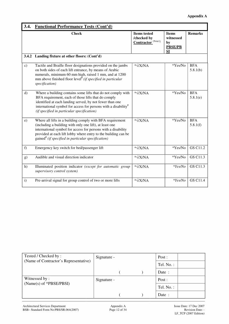
3.4.2 Landing fixture at other floors: (Cont’d) c) Tactile and Braille floor designations provided on the jambs
on both sides of each lift entrance, by means of Arabic numerals, minimum 60 mm high, raised 1 mm, and at 1200 mm above finished floor level# (if specified in particular specification)
*√/X/NA *Yes/No BFA 5.8.1(b)
d) Where a building contains some lifts that do not comply with BFA requirement, each of those lifts that do comply identified at each landing served, by not fewer than one international symbol for access for persons with a disability# (if specified in particular specification)
*√/X/NA *Yes/No BFA 5.8.1(e)
e) Where all lifts in a building comply with BFA requirement (including a building with only one lift), at least one international symbol for access for persons with a disability provided at each lift lobby where entry to the building can be gained# (if specified in particular specification)
*√/X/NA *Yes/No BFA 5.8.1(f)
f) Emergency key switch for bed/passenger lift
*√/X/NA *Yes/No GS C11.2
g) Audible and visual direction indicator
*√/X/NA *Yes/No GS C11.3
h) Illuminated position indicator (except for automatic group supervisory control system)
*√/X/NA *Yes/No GS C11.3
i) Pre-arrival signal for group control of two or more lifts
*√/X/NA *Yes/No GS C11.4
Appendix A
Signature - Post :
Tel. No. :
Tested / Checked by : (Name of Contractor’s Representative)
( ) Date :
Signature - Post :
Tel. No. :
Witnessed by : (Name(s) of *PBSE/PBSI)
( ) Date : Architectural Services Department Appendix A Issue Date: 17 Dec 2007 BSB– Standard Form No:PBS/SR.064(2007) Page 13 of 34 Revision Date: - LF_TCP (2007 Edition)
3.4. Functional Performance Tests (Cont’d) Check Items tested
/checked by Contractor (Note1)
Items witnessed by PBSE/PBSI
Remarks
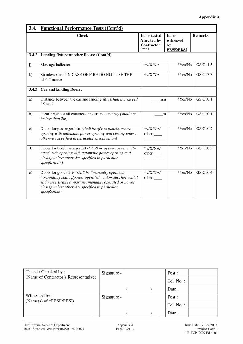
3.4.2 Landing fixture at other floors: (Cont’d) j) Message indicator
*√/X/NA *Yes/No GS C11.5
k) Stainless steel “IN CASE OF FIRE DO NOT USE THE LIFT” notice
*√/X/NA *Yes/No GS C13.3
3.4.3 Car and landing Doors: a) Distance between the car and landing sills (shall not exceed
35 mm)
____mm *Yes/No GS C10.1
b) Clear height of all entrances on car and landings (shall not be less than 2m)
____m *Yes/No GS C10.1
c) Doors for passenger lifts (shall be of two panels, centre opening with automatic power opening and closing unless otherwise specified in particular specification)
*√/X/NA/ other ____ __________
*Yes/No GS C10.2
d) Doors for bed/passenger lifts (shall be of two speed, multi-panel, side opening with automatic power opening and closing unless otherwise specified in particular specification)
*√/X/NA/ other ____ __________
*Yes/No GS C10.3
e) Doors for goods lifts (shall be *manually operated, horizontally sliding/power operated, automatic, horizontal sliding/vertically bi-parting, manually operated or power closing unless otherwise specified in particular specifcation)
*√/X/NA/ other ____ __________
*Yes/No GS C10.4
Appendix A
Signature - Post :
Tel. No. :
Tested / Checked by : (Name of Contractor’s Representative)
( ) Date :
Signature - Post :
Tel. No. :
Witnessed by : (Name(s) of *PBSE/PBSI)
( ) Date : Architectural Services Department Appendix A Issue Date: 17 Dec 2007 BSB– Standard Form No:PBS/SR.064(2007) Page 14 of 34 Revision Date: - LF_TCP (2007 Edition)
3.4. Functional Performance Tests (Cont’d) Check Items tested
/checked by Contractor (Note1)
Items witnessed by PBSE/PBSI
Remarks
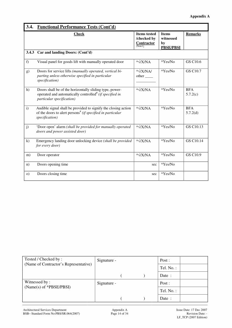
3.4.3 Car and landing Doors: (Cont’d) f) Visual panel for goods lift with manually operated door
*√/X/NA *Yes/No GS C10.6
g) Doors for service lifts (manually operated, vertical bi-parting unless otherwise specified in particular specification)
*√/X/NA/ other ____ __________
*Yes/No GS C10.7
h) Doors shall be of the horizontally sliding type, power-operated and automatically controlled# (if specified in particular specification)
*√/X/NA *Yes/No BFA 5.7.2(c)
i) Audible signal shall be provided to signify the closing action of the doors to alert persons# (if specified in particular specification)
*√/X/NA *Yes/No BFA 5.7.2(d)
j) ‘Door open’ alarm (shall be provided for manually operated doors and power assisted door)
*√/X/NA *Yes/No GS C10.13
k) Emergency landing door unlocking device (shall be provided for every door)
*√/X/NA *Yes/No GS C10.14
m) Door operator
*√/X/NA *Yes/No GS C10.9
n) Doors opening time
sec *Yes/No
o) Doors closing time
sec *Yes/No
Appendix A
Signature - Post :
Tel. No. :
Tested / Checked by : (Name of Contractor’s Representative)
( ) Date :
Signature - Post :
Tel. No. :
Witnessed by : (Name(s) of *PBSE/PBSI)
( ) Date : Architectural Services Department Appendix A Issue Date: 17 Dec 2007 BSB– Standard Form No:PBS/SR.064(2007) Page 15 of 34 Revision Date: - LF_TCP (2007 Edition)
3.4. Functional Performance Tests (Cont’d) Check Items tested
/checked by Contractor (Note1)
Items witnessed by PBSE/PBSI
Remarks
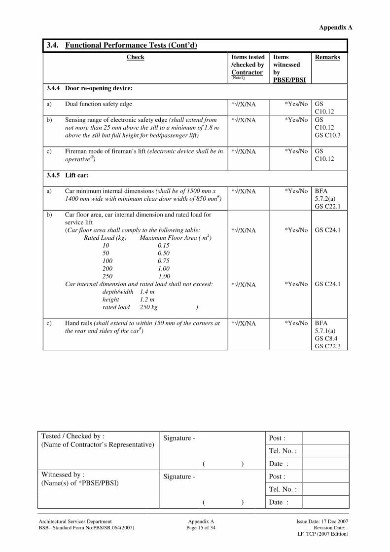
3.4.4 Door re-opening device: a) Dual function safety edge
*√/X/NA *Yes/No GS C10.12
b) Sensing range of electronic safety edge (shall extend from not more than 25 mm above the sill to a minimum of 1.8 m above the sill but full height for bed/passenger lift)
*√/X/NA *Yes/No GS C10.12 GS C10.3
c) Fireman mode of fireman’s lift (electronic device shall be in operative⊗)
*√/X/NA *Yes/No GS C10.12
3.4.5 Lift car: a) Car minimum internal dimensions (shall be of 1500 mm x
1400 mm wide with minimum clear door width of 850 mm#)
*√/X/NA *Yes/No BFA 5.7.2(a) GS C22.1
b) Car floor area, car internal dimension and rated load for service lift
(Car floor area shall comply to the following table: Rated Load (kg) Maximum Floor Area ( m2)
10 0.15 50 0.50 100 0.75 200 1.00 250 1.00
Car internal dimension and rated load shall not exceed: depth/width 1.4 m height 1.2 m rated load 250 kg )
*√/X/NA *√/X/NA
*Yes/No
*Yes/No
GS C24.1 GS C24.1
c) Hand rails (shall extend to within 150 mm of the corners at the rear and sides of the car#)
*√/X/NA *Yes/No BFA 5.7.1(a) GS C8.4 GS C22.3
Appendix A
Signature - Post :
Tel. No. :
Tested / Checked by : (Name of Contractor’s Representative)
( ) Date :
Signature - Post :
Tel. No. :
Witnessed by : (Name(s) of *PBSE/PBSI)
( ) Date : Architectural Services Department Appendix A Issue Date: 17 Dec 2007 BSB– Standard Form No:PBS/SR.064(2007) Page 16 of 34 Revision Date: - LF_TCP (2007 Edition)
3.4. Functional Performance Tests (Cont’d) Check Items tested
/checked by Contractor (Note1)
Items witnessed by PBSE/PBSI
Remarks
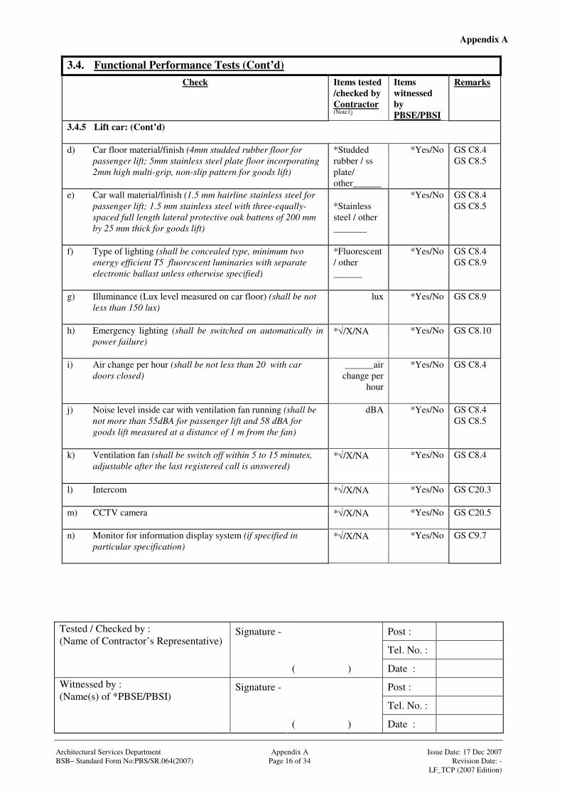
3.4.5 Lift car: (Cont’d) d) Car floor material/finish (4mm studded rubber floor for
passenger lift; 5mm stainless steel plate floor incorporating 2mm high multi-grip, non-slip pattern for goods lift)
*Studded rubber / ss plate/ other______
*Yes/No GS C8.4 GS C8.5
e) Car wall material/finish (1.5 mm hairline stainless steel for passenger lift; 1.5 mm stainless steel with three-equally-spaced full length lateral protective oak battens of 200 mm by 25 mm thick for goods lift)
*Stainless steel / other _______
*Yes/No GS C8.4 GS C8.5
f) Type of lighting (shall be concealed type, minimum two energy efficient T5 fluorescent luminaries with separate electronic ballast unless otherwise specified)
*Fluorescent/ other ______
*Yes/No GS C8.4 GS C8.9
g) Illuminance (Lux level measured on car floor) (shall be not less than 150 lux)
lux *Yes/No GS C8.9
h) Emergency lighting (shall be switched on automatically in power failure)
*√/X/NA *Yes/No GS C8.10
i) Air change per hour (shall be not less than 20 with car doors closed)
______air change per
hour
*Yes/No GS C8.4
j) Noise level inside car with ventilation fan running (shall be not more than 55dBA for passenger lift and 58 dBA for goods lift measured at a distance of 1 m from the fan)
dBA *Yes/No GS C8.4 GS C8.5
k) Ventilation fan (shall be switch off within 5 to 15 minutes, adjustable after the last registered call is answered)
*√/X/NA
*Yes/No GS C8.4
l) Intercom
*√/X/NA *Yes/No GS C20.3
m) CCTV camera
*√/X/NA *Yes/No GS C20.5
n) Monitor for information display system (if specified in particular specification)
*√/X/NA *Yes/No GS C9.7
Appendix A
Signature - Post :
Tel. No. :
Tested / Checked by : (Name of Contractor’s Representative)
( ) Date :
Signature - Post :
Tel. No. :
Witnessed by : (Name(s) of *PBSE/PBSI)
( ) Date : Architectural Services Department Appendix A Issue Date: 17 Dec 2007 BSB– Standard Form No:PBS/SR.064(2007) Page 17 of 34 Revision Date: - LF_TCP (2007 Edition)
3.4. Functional Performance Tests (Cont’d) Check Items tested
/checked by Contractor (Note1)
Items witnessed by PBSE/PBSI
Remarks
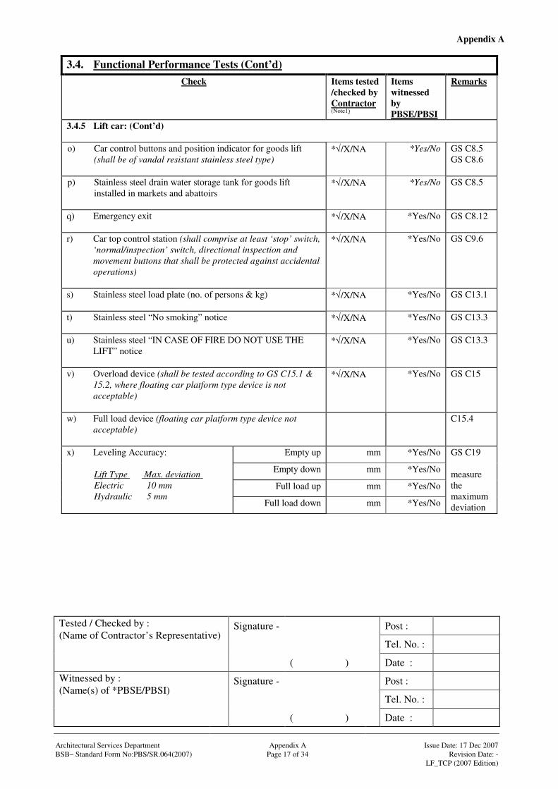
3.4.5 Lift car: (Cont’d) o) Car control buttons and position indicator for goods lift
(shall be of vandal resistant stainless steel type)
*√/X/NA *Yes/No GS C8.5 GS C8.6
p) Stainless steel drain water storage tank for goods lift installed in markets and abattoirs
*√/X/NA *Yes/No GS C8.5
q) Emergency exit
*√/X/NA *Yes/No GS C8.12
r) Car top control station (shall comprise at least ‘stop’ switch, ‘normal/inspection’ switch, directional inspection and movement buttons that shall be protected against accidental operations)
*√/X/NA *Yes/No GS C9.6
s) Stainless steel load plate (no. of persons & kg)
*√/X/NA *Yes/No GS C13.1
t) Stainless steel “No smoking” notice
*√/X/NA *Yes/No GS C13.3
u) Stainless steel “IN CASE OF FIRE DO NOT USE THE LIFT” notice
*√/X/NA *Yes/No GS C13.3
v) Overload device (shall be tested according to GS C15.1 & 15.2, where floating car platform type device is not acceptable)
*√/X/NA *Yes/No GS C15
w) Full load device (floating car platform type device not acceptable)
C15.4
Empty up mm *Yes/No
Empty down mm *Yes/No
Full load up mm *Yes/No
x) Leveling Accuracy:
Lift Type Max. deviation Electric 10 mm Hydraulic 5 mm
Full load down mm *Yes/No
GS C19 measure the maximum deviation

Appendix A
Signature - Post :
Tel. No. :
Tested / Checked by : (Name of Contractor’s Representative)
( ) Date :
Signature - Post :
Tel. No. :
Witnessed by : (Name(s) of *PBSE/PBSI)
( ) Date : Architectural Services Department Appendix A Issue Date: 17 Dec 2007 BSB– Standard Form No:PBS/SR.064(2007) Page 18 of 34 Revision Date: - LF_TCP (2007 Edition)
3.4. Functional Performance Tests (Cont’d) Check Items tested
/checked by Contractor (Note1)
Items witnessed by PBSE/PBSI
Remarks
3.4.6 Control station in car: a) Call button with acceptance signal (shall be engraved in
Arabic number to correspond with the landing served)
*√/X/NA *Yes/No GS C9.1
b) “Door open” & “Door close” push buttons
*√/X/NA *Yes/No GS C9.1
c) Audible & visible signals for overload
*√/X/NA *Yes/No GS C9.1
d) Two-way intercom system
*√/X/NA *Yes/No GS C9.1 GS C20.3
e) Alarm push button with protection from being operated accidentally (if specified in particular specification) (the colour shall be yellow; for Barrier Free Access lift, the emergency alarm push button shall be in tactile bell shape#)
*√/X/Tactile bell/NA
*Yes/No GS C9.1 GS C22 BFA 5.7.1(e)
f) Graphics for tactile markings for open-door and close-door push buttons, emergency alarm button, and main entrance level in accordance with Fig. 14 of Design Manual Barrier Free Access# (if specified in particular specification)
*√/X/NA *Yes/No GS C22 BFA 5.7.2(e)
g) Position of essential lift control buttons (i.e. emergency alarm push button, control to activate intercom, and door opening push buttons) not less than 900 mm and not more than 1200 mm above the floor of the lift car# (if specified in particular specification)
*√/X/NA *Yes/No GS C22 BFA 5.7.1(c)
Appendix A
Signature - Post :
Tel. No. :
Tested / Checked by : (Name of Contractor’s Representative)
( ) Date :
Signature - Post :
Tel. No. :
Witnessed by : (Name(s) of *PBSE/PBSI)
( ) Date : Architectural Services Department Appendix A Issue Date: 17 Dec 2007 BSB– Standard Form No:PBS/SR.064(2007) Page 19 of 34 Revision Date: - LF_TCP (2007 Edition)
3.4. Functional Performance Tests (Cont’d) Check Items tested
/checked by Contractor (Note1)
Items witnessed by PBSE/PBSI
Remarks
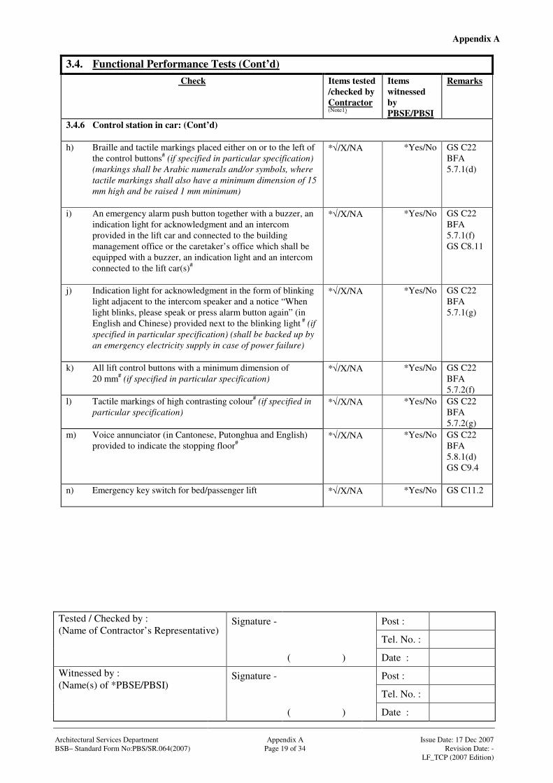
3.4.6 Control station in car: (Cont’d) h) Braille and tactile markings placed either on or to the left of
the control buttons# (if specified in particular specification) (markings shall be Arabic numerals and/or symbols, where tactile markings shall also have a minimum dimension of 15 mm high and be raised 1 mm minimum)
*√/X/NA *Yes/No GS C22 BFA 5.7.1(d)
i) An emergency alarm push button together with a buzzer, an indication light for acknowledgment and an intercom provided in the lift car and connected to the building management office or the caretaker’s office which shall be equipped with a buzzer, an indication light and an intercom connected to the lift car(s)#
*√/X/NA *Yes/No GS C22 BFA 5.7.1(f) GS C8.11
j) Indication light for acknowledgment in the form of blinking light adjacent to the intercom speaker and a notice “When light blinks, please speak or press alarm button again” (in English and Chinese) provided next to the blinking light # (if specified in particular specification) (shall be backed up by an emergency electricity supply in case of power failure)
*√/X/NA *Yes/No GS C22 BFA 5.7.1(g)
k) All lift control buttons with a minimum dimension of 20 mm# (if specified in particular specification)
*√/X/NA *Yes/No GS C22 BFA 5.7.2(f)
l) Tactile markings of high contrasting colour# (if specified in particular specification)
*√/X/NA *Yes/No GS C22 BFA 5.7.2(g)
m) Voice annunciator (in Cantonese, Putonghua and English) provided to indicate the stopping floor#
*√/X/NA *Yes/No GS C22 BFA 5.8.1(d) GS C9.4
n) Emergency key switch for bed/passenger lift
*√/X/NA *Yes/No GS C11.2
Appendix A
Signature - Post :
Tel. No. :
Tested / Checked by : (Name of Contractor’s Representative)
( ) Date :
Signature - Post :
Tel. No. :
Witnessed by : (Name(s) of *PBSE/PBSI)
( ) Date : Architectural Services Department Appendix A Issue Date: 17 Dec 2007 BSB– Standard Form No:PBS/SR.064(2007) Page 20 of 34 Revision Date: - LF_TCP (2007 Edition)
3.4. Functional Performance Tests (Cont’d) Check Items tested
/checked by Contractor (Note1)
Items witnessed by PBSE/PBSI
Remarks
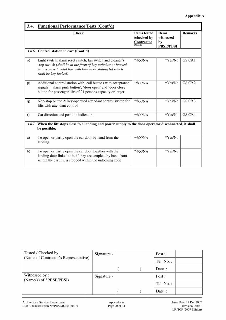
3.4.6 Control station in car: (Cont’d) o) Light switch, alarm reset switch, fan switch and cleaner’s
stop-switch (shall be in the form of key switches or housed in a recessed metal box with hinged or sliding lid which shall be key-locked)
*√/X/NA *Yes/No GS C9.1
p) Additional control station with ‘call buttons with acceptance signals’, ‘alarm push button’, ‘door open’ and ‘door close’ button for passenger lifts of 21 persons capacity or larger
*√/X/NA *Yes/No GS C9.2
q) Non-stop button & key-operated attendant control switch for lifts with attendant control
*√/X/NA *Yes/No GS C9.3
r) Car direction and position indicator
*√/X/NA *Yes/No GS C9.4
3.4.7 When the lift stops close to a landing and power supply to the door operator disconnected, it shall be possible:
a) To open or partly open the car door by hand from the
landing
*√/X/NA *Yes/No
b) To open or partly open the car door together with the landing door linked to it, if they are coupled, by hand from within the car if it is stopped within the unlocking zone
*√/X/NA *Yes/No
Appendix A
Signature - Post :
Tel. No. :
Tested / Checked by : (Name of Contractor’s Representative)
( ) Date :
Signature - Post :
Tel. No. :
Witnessed by : (Name(s) of *PBSE/PBSI)
( ) Date : Architectural Services Department Appendix A Issue Date: 17 Dec 2007 BSB– Standard Form No:PBS/SR.064(2007) Page 21 of 34 Revision Date: - LF_TCP (2007 Edition)
3.4. Functional Performance Tests (Cont’d) Check Items tested
/checked by Contractor (Note1)
Items witnessed by PBSE/PBSI
Remarks
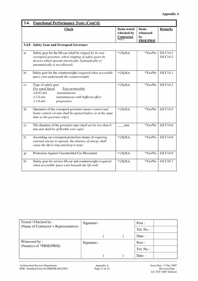
3.4.8 Safety Gear and Overspeed Governor: a) Safety gear for the lift car (shall be tripped by its own
overspeed governor, where tripping of safety gears by devices which operate electrically, hydraulically or pneumatically is not allowed)
*√/X/NA *Yes/No GS C14.1 GS C14.2
b) Safety gear for the counterweight (required when accessible space exist underneath the counterweight)
*√/X/NA *Yes/No GS C14.1
c) Type of safety gear For rated Speed Type permissible ≤ 0.63 m/s instantaneous ≤ 1.0 m/s instantaneous with buffered effect > 1.0 m/s progressive
*√/X/NA *Yes/No GS C14.3
d) Operation of the overspeed governor (motor control and brake control circuits shall be opened before or at the same time as the governor trips)
*√/X/NA *Yes/No GS C14.5
e) The diameter of the governor rope (shall not be less than 6 mm and shall be of flexible wire rope)
____mm *Yes/No GS C14.6
f) Ascending car overspeed protection means (if requiring external energy to operate, the absence of energy shall cause the lift to stop and keep it stop)
*√/X/NA *Yes/No GS C14.8
g) Protection Against Uncontrolled Car Movement
*√/X/NA *Yes/No GS C14.9
h) Safety gear for service lift car and counterweight (required when accessible space exist beneath the lift well)
*√/X/NA *Yes/No GS C24.7

Appendix A
Signature - Post :
Tel. No. :
Tested / Checked by : (Name of Contractor’s Representative)
( ) Date :
Signature - Post :
Tel. No. :
Witnessed by : (Name(s) of *PBSE/PBSI)
( ) Date : Architectural Services Department Appendix A Issue Date: 17 Dec 2007 BSB– Standard Form No:PBS/SR.064(2007) Page 22 of 34 Revision Date: - LF_TCP (2007 Edition)
3.4. Functional Performance Tests (Cont’d) Check Items tested
/checked by Contractor (Note1)
Items witnessed by PBSE/PBSI
Remarks
3.4.9 Automatic Control System (the following control system shall be tested according to the lift manufacturer’s recommended procedure and methodology. Any special testing equipment required, such as portable computer, shall be provided by the Contractor):
a) All lifts other than service lifts (full load device shall be
provided, which will detect the load condition and allow landing calls to be by-passed)
*√/X/NA
*Yes/No GS C18.1
b) Single lift with automatic push button control (shall allow only one call to be registered at a time, where the car shall answer one call before another call can be registered)
*√/X/NA
*Yes/No GS C18.2
c) Single lift with down collective control (Simplex) (see GS C18.3 for the detailed control algorithm)
*√/X/NA
*Yes/No GS C18.3
d) Two inter-connected lifts with down collective control (Duplex) (see GS C18.4 for the detailed control algorithm)
*√/X/NA
*Yes/No GS C18.4
e) Single lift with directional collective control (see GS C18.5 for the detailed control algorithm)
*√/X/NA
*Yes/No GS C18.5
f) Two inter-connected lifts with directional collective control (see GS C18.6 for the detailed control algorithm)
*√/X/NA
*Yes/No GS C18.6
g) 2-8 inter-connected lifts with automatic group supervisory control (see GS C18.7 for the detailed control algorithm regarding (1) flexible service sectors;(2) heavy “Up” traffic; (3) heavy “Down” traffic; (4) light traffic; (5) pre-arrival chiming; (6) traffic sentinel; (7) car preference; (8) car separation)
*√/X/NA
*Yes/No GS C18.7
h) Group operation of lifts under emergency power supply (automatic selector switch shall be provided and the operation of the fireman’s lift(s) shall not be affected in any case)
*√/X/NA
*Yes/No GS C18.7
i) Standby mode during off-peak for energy management (in general, at least one lift car of a lift bank shall operate under a standby mode during off-peak period when the traffic demand is low)
*√/X/NA
*Yes/No GS B4.6

Appendix A
Signature - Post :
Tel. No. :
Tested / Checked by : (Name of Contractor’s Representative)
( ) Date :
Signature - Post :
Tel. No. :
Witnessed by : (Name(s) of *PBSE/PBSI)
( ) Date : Architectural Services Department Appendix A Issue Date: 17 Dec 2007 BSB– Standard Form No:PBS/SR.064(2007) Page 23 of 34 Revision Date: - LF_TCP (2007 Edition)
3.4. Functional Performance Tests (Cont’d) Check Items tested
/checked by Contractor (Note1)
Items witnessed by PBSE/PBSI
Remarks
3.4.10 Machine Room: a) Power supply points provided by others *√/X/NA *Yes/No GS B2.1
& 2.2 b) Direction indicator on machine
*√/X/NA *Yes/No
c) Direction indicator on governor
*√/X/NA *Yes/No
d) Hoist rope shall be well set into groove
*√/X/NA *Yes/No
e) Provision for future Energy Audit (multi-functional metering devices (A) or permanent provisions for connection of such devices (C) shall be provided)
*√/X/NA
*(A)/(C)
*Yes/No GS B4.2
f) A board or suitable container for the necessary tools, together with clear instructions on the method for releasing the brake and moving the lift car in an emergency provided and positioned in a conspicuous manner
*√/X/NA (detail
_________)
*Yes/No GS C13.4
g) Fire extinguisher provided by others *√/X/NA
*Yes/No
h) Handrail provided by others
*√/X/NA *Yes/No
i) Lighting provided by others
*√/X/NA *Yes/No
j) Log book provided
*√/X/NA *Yes/No
3.4.11 Driving Machinery: a) Motor starting full load up/no load down shall be without
any roll back
*√/X/NA *Yes/No
b) Motor enclosure, class of cooling IP________ IC________
*Yes/No
Appendix A
Signature - Post :
Tel. No. :
Tested / Checked by : (Name of Contractor’s Representative)
( ) Date :
Signature - Post :
Tel. No. :
Witnessed by : (Name(s) of *PBSE/PBSI)
( ) Date : Architectural Services Department Appendix A Issue Date: 17 Dec 2007 BSB– Standard Form No:PBS/SR.064(2007) Page 24 of 34 Revision Date: - LF_TCP (2007 Edition)
3.4. Functional Performance Tests (Cont’d) Check Items tested
/checked by Contractor (Note1)
Items witnessed by PBSE/PBSI
Remarks
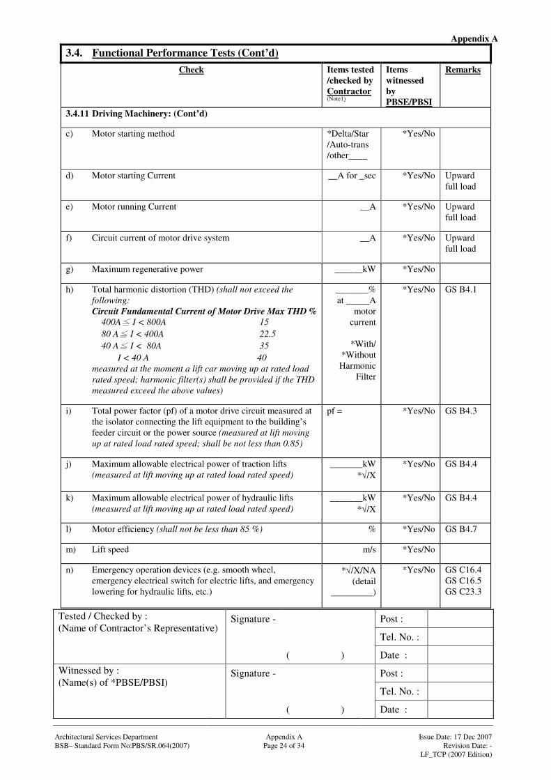
3.4.11 Driving Machinery: (Cont’d) c) Motor starting method
*Delta/Star /Auto-trans /other____
*Yes/No
d) Motor starting Current __A for _sec *Yes/No Upward full load
e) Motor running Current __A *Yes/No Upward full load
f) Circuit current of motor drive system
__A *Yes/No Upward full load
g) Maximum regenerative power
______kW *Yes/No
h) Total harmonic distortion (THD) (shall not exceed the following:
Circuit Fundamental Current of Motor Drive Max THD % 400A I < 800A 15 80 A I < 400A 22.5 40 A I < 80A 35 I < 40 A 40 measured at the moment a lift car moving up at rated load
rated speed; harmonic filter(s) shall be provided if the THD measured exceed the above values)
_______% at _____A
motor current
*With/
*Without Harmonic
Filter
*Yes/No GS B4.1
i) Total power factor (pf) of a motor drive circuit measured at the isolator connecting the lift equipment to the building’s feeder circuit or the power source (measured at lift moving up at rated load rated speed; shall be not less than 0.85)
pf = *Yes/No GS B4.3
j) Maximum allowable electrical power of traction lifts (measured at lift moving up at rated load rated speed)
_______kW *√/X
*Yes/No GS B4.4
k) Maximum allowable electrical power of hydraulic lifts (measured at lift moving up at rated load rated speed)
_______kW *√/X
*Yes/No GS B4.4
l) Motor efficiency (shall not be less than 85 %)
% *Yes/No GS B4.7
m) Lift speed
m/s *Yes/No
n) Emergency operation devices (e.g. smooth wheel, emergency electrical switch for electric lifts, and emergency lowering for hydraulic lifts, etc.)
*√/X/NA (detail
_________)
*Yes/No GS C16.4 GS C16.5 GS C23.3

Appendix A
Signature - Post :
Tel. No. :
Tested / Checked by : (Name of Contractor’s Representative)
( ) Date :
Signature - Post :
Tel. No. :
Witnessed by : (Name(s) of *PBSE/PBSI)
( ) Date : Architectural Services Department Appendix A Issue Date: 17 Dec 2007 BSB– Standard Form No:PBS/SR.064(2007) Page 25 of 34 Revision Date: - LF_TCP (2007 Edition)
3.4. Functional Performance Tests (Cont’d) Check Items tested
/checked by Contractor (Note1)
Items witnessed by PBSE/PBSI
Remarks
3.4.12 Lift well & pit: a) Function of permanent lighting provided by others in lift
well with two ways switch at lift pit & machine room
*√/X/NA
*Yes/No GS B2.2
b) Function of interlock among emergency doors and electric safety device
*√/X/NA
*Yes/No GS C10.14
c) Types of traveling cables complying with the GS: Max. Speed Type permissible
≤ 1.0 m/s rubber insulated & sheathed, flexible 3 to 18 cores maximum freely suspended length15 m ≤ 1.6 m/s rubber insulated & sheathed, flexible 4 to 48 cores@
maximum freely suspended length 35 m
≤ 1.6 m/s PVC insulated & sheathed, flexible 3 to 24 cores @
maximum freely suspended length 35 m
No limit PVC insulated & sheathed, flexible 4 to 72cores No limit on maximum freely suspended length No limit Rubber insulated & sheathed, flexible 36 to72cores having strain-bearing center No limit on maximum freely suspended length @ Higher limits permissible if strain bearing material is
included
*√/X/NA
*Yes/No GS B2.5
d) Travelling cables (shall be properly fixed with no twist or kink while travelling)
*√/X/NA *Yes/No GS B2.5
e) Function of lift pit lighting provided by others
*√/X/NA
*Yes/No GS B2.2
f) Screen between adjacent cars in lift pit provided by others
*√/X/NA
*Yes/No GS C6.2
g) Screen for counterweight in lift pit provided by others
*√/X/NA
*Yes/No GS C6.3
h) Function of drain provided by others in lift pit
*√/X/NA
*Yes/No
i) Function of submersible pump in lift pit *√/X/NA
*Yes/No
j) Cat ladder provided by others in lift pit *√/X/NA
*Yes/No
k) Cleanliness and dryness of lift pit
*√/X/NA
*Yes/No
Appendix A
Signature - Post :
Tel. No. :
Tested / Checked by : (Name of Contractor’s Representative)
( ) Date :
Signature - Post :
Tel. No. :
Witnessed by : (Name(s) of *PBSE/PBSI)
( ) Date : Architectural Services Department Appendix A Issue Date: 17 Dec 2007 BSB– Standard Form No:PBS/SR.064(2007) Page 26 of 34 Revision Date: - LF_TCP (2007 Edition)
3.4. Functional Performance Tests (Cont’d) Check Items tested
/checked by Contractor (Note1)
Items witnessed by PBSE/PBSI
Remarks
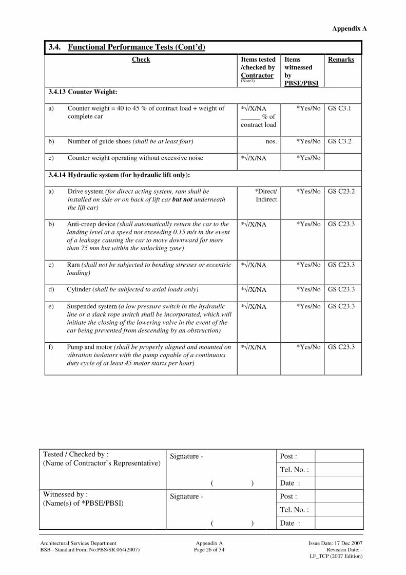
3.4.13 Counter Weight: a) Counter weight = 40 to 45 % of contract load + weight of
complete car
*√/X/NA % of contract load
*Yes/No GS C3.1
b) Number of guide shoes (shall be at least four)
nos. *Yes/No GS C3.2
c) Counter weight operating without excessive noise
*√/X/NA
*Yes/No
3.4.14 Hydraulic system (for hydraulic lift only): a) Drive system (for direct acting system, ram shall be
installed on side or on back of lift car but not underneath the lift car)
*Direct/ Indirect
*Yes/No GS C23.2
b) Anti-creep device (shall automatically return the car to the landing level at a speed not exceeding 0.15 m/s in the event of a leakage causing the car to move downward for more than 75 mm but within the unlocking zone)
*√/X/NA
*Yes/No GS C23.3
c) Ram (shall not be subjected to bending stresses or eccentric loading)
*√/X/NA
*Yes/No GS C23.3
d) Cylinder (shall be subjected to axial loads only)
*√/X/NA
*Yes/No GS C23.3
e) Suspended system (a low pressure switch in the hydraulic line or a slack rope switch shall be incorporated, which will initiate the closing of the lowering valve in the event of the car being prevented from descending by an obstruction)
*√/X/NA
*Yes/No GS C23.3
f) Pump and motor (shall be properly aligned and mounted on vibration isolators with the pump capable of a continuous duty cycle of at least 45 motor starts per hour)
*√/X/NA
*Yes/No GS C23.3

Appendix A
Signature - Post :
Tel. No. :
Tested / Checked by : (Name of Contractor’s Representative)
( ) Date :
Signature - Post :
Tel. No. :
Witnessed by : (Name(s) of *PBSE/PBSI)
( ) Date : Architectural Services Department Appendix A Issue Date: 17 Dec 2007 BSB– Standard Form No:PBS/SR.064(2007) Page 27 of 34 Revision Date: - LF_TCP (2007 Edition)
3.4. Functional Performance Tests (Cont’d) Check Items tested
/checked by Contractor (Note1)
Items witnessed by PBSE/PBSI
Remarks
3.4.14 Hydraulic system (for hydraulic lift only): (Cont’d) g) Hydraulic System (shall be fitted with a silencer unit and
with oil filter on the pump inlet with stop cock for filter cleaning and filter change)
*√/X/NA
*Yes/No GS C23.3
h) Pump flow rate
litre/sec *Yes/No GS C23.3
i) Working pressure
kPa *Yes/No GS C23.3
j) Oil tank capacity (shall be adequate to prevent the entrance of air or gases into the system)
litres *Yes/No GS C23.3
k) Sight glass tube for oil tank provided
*√/X/NA *Yes/No GS C23.3
l) Oil level monitoring device (shall give a visual and audible signal in the control panel when the oil level is at alarming low level)
*√/X/NA *Yes/No GS C23.3
m) Rigid steel pipe (shall be effectively isolated from the building structure)
*√/X/NA *Yes/No GS C23.3
n) Safety Gear fitted to direct acting hydraulic lift (not instantaneous type and shall be made to absorb any impact loading at the cross-head due to the inertia of the ram and attachments)
*√/X/NA *Yes/No GS C23.6
o) Safety Gear – integral or flange-bolted rupture valve (shall stop the descent of car cage)
*√/X/NA *Yes/No GS C23.6
p) Re-levelling device (shall automatically return the lift to the floor should the lift creep down from floor level for a distance not exceeding 75 mm)
*√/X/NA *Yes/No GS C23.7
Appendix A
Signature - Post :
Tel. No. :
Tested / Checked by : (Name of Contractor’s Representative)
( ) Date :
Signature - Post :
Tel. No. :
Witnessed by : (Name(s) of *PBSE/PBSI)
( ) Date : Architectural Services Department Appendix A Issue Date: 17 Dec 2007 BSB– Standard Form No:PBS/SR.064(2007) Page 28 of 34 Revision Date: - LF_TCP (2007 Edition)
3.4. Functional Performance Tests (Cont’d) Check Items tested
/checked by Contractor (Note1)
Items witnessed by PBSE/PBSI
Remarks
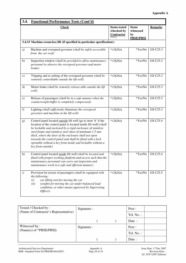
3.4.15 Machine-room-less lift (if specified in particular specification): a) Machine and overspeed governor (shall be safely accessible
from the car roof)
*√/X/NA *Yes/No GS C25.3
b) Inspection window (shall be provided to allow maintenance personnel to observe the overspeed governor and motor brake)
*√/X/NA *Yes/No GS C25.3
c) Tripping and re-setting of the overspeed governor (shall be remotely controllable outside the lift well)
*√/X/NA *Yes/No GS C25.3
d) Motor brake (shall be remotely release-able outside the lift well)
*√/X/NA *Yes/No GS C25.3
e) Release of passengers (shall be in a safe manner when the counterweight buffer is completely compressed)
*√/X/NA *Yes/No GS C25.3
f) Lighting (shall sufficiently illuminate the overspeed governor and machine in the lift well)
*√/X/NA *Yes/No GS C25.3
g) Control panel located outside lift well (go to item ‘h’ if the location of the control panel is located inside lift well) (shall be lockable and enclosed by a rigid enclosure of stainless steel frame and stainless steel sheet of minimum 1.5 mm thick, where the door of the enclosure shall not open towards the control panel and shall be fitted with a lock openable without a key from inside and lockable without a key from outside)
*√/X/NA *Yes/No GS C25.4
h) Control panel located inside lift well (shall be located and fitted with proper working platform and access such that the maintenance personnel can carry out inspection and maintenance work in a safe and efficient manner)
*√/X/NA *Yes/No GS C25.4
i) Provision for rescue of passengers (shall be equipped with the following: (i) car lifting tool for moving the car (ii) weights for moving the car under balanced load
condition, or other means approved by Supervising Officer)
*√/X/NA *Yes/No GS C25.5
Appendix A
Signature - Post :
Tel. No. :
Tested / Checked by : (Name of Contractor’s Representative)
( ) Date :
Signature - Post :
Tel. No. :
Witnessed by : (Name(s) of *PBSE/PBSI)
( ) Date : Architectural Services Department Appendix A Issue Date: 17 Dec 2007 BSB– Standard Form No:PBS/SR.064(2007) Page 29 of 34 Revision Date: - LF_TCP (2007 Edition)
3.4. Functional Performance Tests (Cont’d) Check Items tested
/checked by Contractor (Note1)
Items witnessed by PBSE/PBSI
Remarks
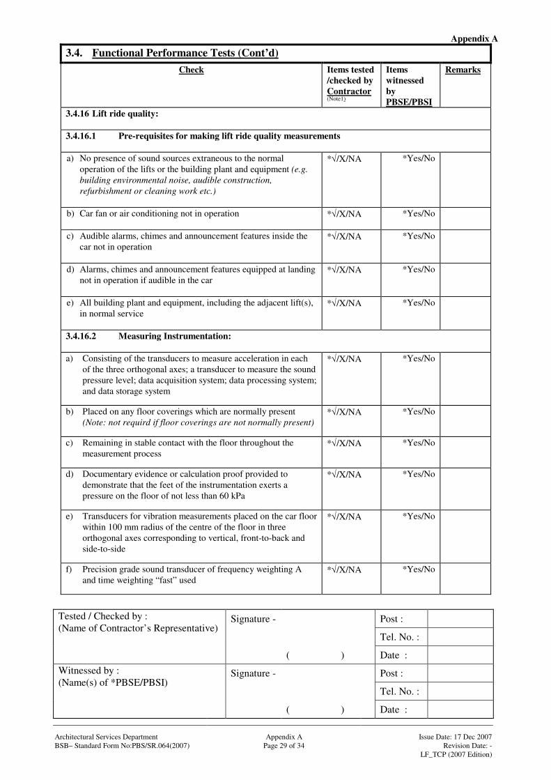
3.4.16 Lift ride quality: 3.4.16.1 Pre-requisites for making lift ride quality measurements a) No presence of sound sources extraneous to the normal
operation of the lifts or the building plant and equipment (e.g. building environmental noise, audible construction, refurbishment or cleaning work etc.)
*√/X/NA *Yes/No
b) Car fan or air conditioning not in operation
*√/X/NA *Yes/No
c) Audible alarms, chimes and announcement features inside the car not in operation
*√/X/NA *Yes/No
d) Alarms, chimes and announcement features equipped at landing not in operation if audible in the car
*√/X/NA *Yes/No
e) All building plant and equipment, including the adjacent lift(s), in normal service
*√/X/NA *Yes/No
3.4.16.2 Measuring Instrumentation: a) Consisting of the transducers to measure acceleration in each
of the three orthogonal axes; a transducer to measure the sound pressure level; data acquisition system; data processing system; and data storage system
*√/X/NA *Yes/No
b) Placed on any floor coverings which are normally present (Note: not requird if floor coverings are not normally present)
*√/X/NA *Yes/No
c) Remaining in stable contact with the floor throughout the measurement process
*√/X/NA *Yes/No
d) Documentary evidence or calculation proof provided to demonstrate that the feet of the instrumentation exerts a pressure on the floor of not less than 60 kPa
*√/X/NA *Yes/No
e) Transducers for vibration measurements placed on the car floor within 100 mm radius of the centre of the floor in three orthogonal axes corresponding to vertical, front-to-back and side-to-side
*√/X/NA *Yes/No
f) Precision grade sound transducer of frequency weighting A and time weighting “fast” used
*√/X/NA *Yes/No
Appendix A
Signature - Post :
Tel. No. :
Tested / Checked by : (Name of Contractor’s Representative)
( ) Date :
Signature - Post :
Tel. No. :
Witnessed by : (Name(s) of *PBSE/PBSI)
( ) Date : Architectural Services Department Appendix A Issue Date: 17 Dec 2007 BSB– Standard Form No:PBS/SR.064(2007) Page 30 of 34 Revision Date: - LF_TCP (2007 Edition)
3.4. Functional Performance Tests (Cont’d) Check Items tested
/checked by Contractor (Note1)
Items witnessed by PBSE/PBSI
Remarks
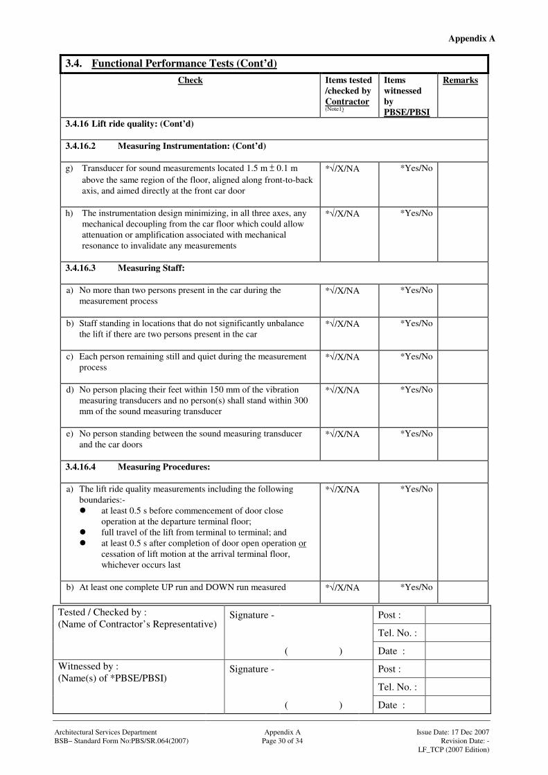
3.4.16 Lift ride quality: (Cont’d) 3.4.16.2 Measuring Instrumentation: (Cont’d) g) Transducer for sound measurements located 1.5 m 0.1 m
above the same region of the floor, aligned along front-to-back axis, and aimed directly at the front car door
*√/X/NA *Yes/No
h) The instrumentation design minimizing, in all three axes, any mechanical decoupling from the car floor which could allow attenuation or amplification associated with mechanical resonance to invalidate any measurements
*√/X/NA *Yes/No
3.4.16.3 Measuring Staff: a) No more than two persons present in the car during the
measurement process
*√/X/NA *Yes/No
b) Staff standing in locations that do not significantly unbalance the lift if there are two persons present in the car
*√/X/NA *Yes/No
c) Each person remaining still and quiet during the measurement process
*√/X/NA *Yes/No
d) No person placing their feet within 150 mm of the vibration measuring transducers and no person(s) shall stand within 300 mm of the sound measuring transducer
*√/X/NA *Yes/No
e) No person standing between the sound measuring transducer and the car doors
*√/X/NA *Yes/No
3.4.16.4 Measuring Procedures: a) The lift ride quality measurements including the following
boundaries:- at least 0.5 s before commencement of door close
operation at the departure terminal floor; full travel of the lift from terminal to terminal; and at least 0.5 s after completion of door open operation or
cessation of lift motion at the arrival terminal floor, whichever occurs last
*√/X/NA *Yes/No
b) At least one complete UP run and DOWN run measured
*√/X/NA *Yes/No
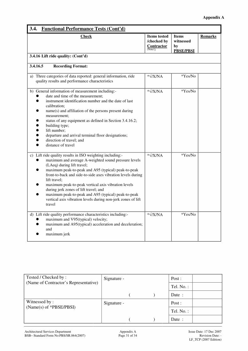
Appendix A
Signature - Post :
Tel. No. :
Tested / Checked by : (Name of Contractor’s Representative)
( ) Date :
Signature - Post :
Tel. No. :
Witnessed by : (Name(s) of *PBSE/PBSI)
( ) Date : Architectural Services Department Appendix A Issue Date: 17 Dec 2007 BSB– Standard Form No:PBS/SR.064(2007) Page 31 of 34 Revision Date: - LF_TCP (2007 Edition)
3.4. Functional Performance Tests (Cont’d) Check Items tested
/checked by Contractor (Note1)
Items witnessed by PBSE/PBSI
Remarks
3.4.16 Lift ride quality: (Cont’d) 3.4.16.5 Recording Format: a) Three categories of data reported: general information, ride
quality results and performance characteristics
*√/X/NA *Yes/No
b) General information of measurement including:- date and time of the measurement; instrument identification number and the date of last
calibration; name(s) and affiliation of the persons present during
measurement; status of any equipment as defined in Section 3.4.16.2; building type; lift number; departure and arrival terminal floor designations; direction of travel; and distance of travel
*√/X/NA *Yes/No
c) Lift ride quality results in ISO weighting including:- maximum and average A-weighted sound pressure levels
(LAeq) during lift travel; maximum peak-to-peak and A95 (typical) peak-to-peak
front-to-back and side-to-side axes vibration levels during lift travel;
maximum peak-to-peak vertical axis vibration levels during jerk zones of lift travel; and
maximum peak-to-peak and A95 (typical) peak-to-peak vertical axis vibration levels during non-jerk zones of lift travel
*√/X/NA *Yes/No
d) Lift ride quality performance characteristics including:- maximum and V95(typical) velocity; maximum and A95(typical) acceleration and deceleration;
and maximum jerk
*√/X/NA *Yes/No

Appendix A
Signature - Post :
Tel. No. :
Tested / Checked by : (Name of Contractor’s Representative)
( ) Date :
Signature - Post :
Tel. No. :
Witnessed by : (Name(s) of *PBSE/PBSI)
( ) Date : Architectural Services Department Appendix A Issue Date: 17 Dec 2007 BSB– Standard Form No:PBS/SR.064(2007) Page 32 of 34 Revision Date: - LF_TCP (2007 Edition)
3.4. Functional Performance Tests (Cont’d) Check Items tested
/checked by Contractor (Note1)
Items witnessed by PBSE/PBSI
Remarks
3.4.16 Lift ride quality: (Cont’d) 3.4.16.6 Acceptance Criteria: a) Lateral and vertical vibrations
Acceptable standards:- [ISO weighting?] Maximum peak-to-peak
vibration Lift speed
< 6 m/s Lift speed 6 to 8 m/s
Lateral (m/s2) 0.25 0.375 Vertical (m/s2) 0.25 0.375
Lateral: m/s2
Vertical:
m/s2
*Yes/No GS B5.2
b) Noise level Acceptable level:-
Without car fan or air conditioning in operation
All lift speeds
Average A-weighted sound pressure level, LAeq (dB(A))
55
dBA *Yes/No GS B5.3
c) Acceleration and deceleration Acceptable rates:-
Maximum All lift speeds Acceleration and deceleration (m/s2) 1
Accelaration: m/s2
Decelaration:
m/s2
*Yes/No GS B5.4
d) Jerk level Acceptable level:-
Maximum All lift speeds Jerk (m/s3) 4
m/s3 *Yes/No GS B5.5
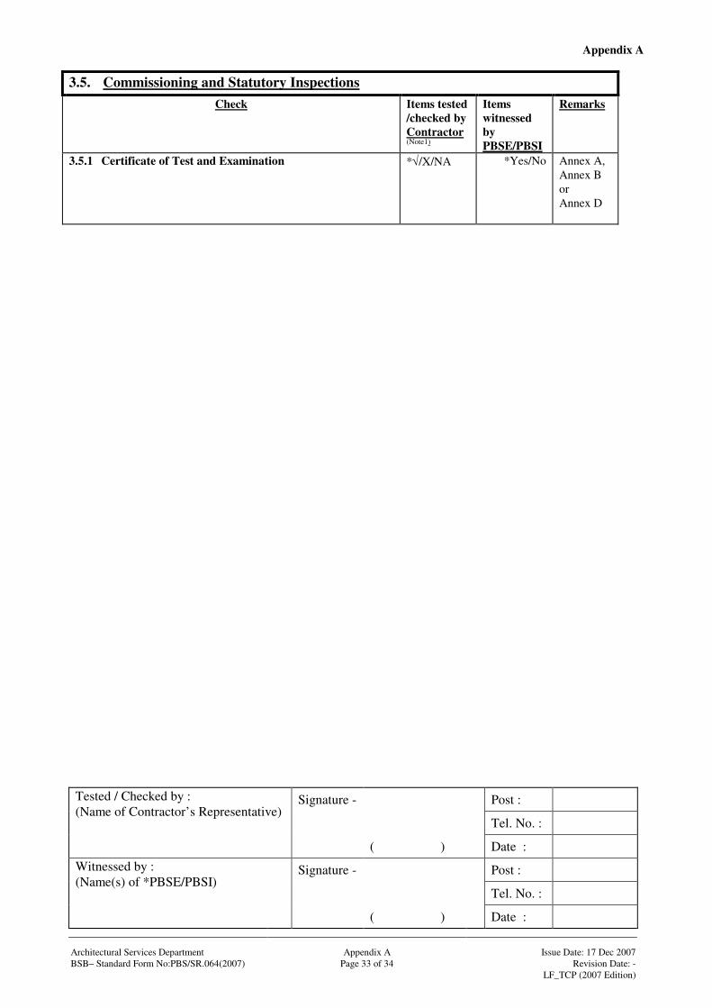
Appendix A
Signature - Post :
Tel. No. :
Tested / Checked by : (Name of Contractor’s Representative)
( ) Date :
Signature - Post :
Tel. No. :
Witnessed by : (Name(s) of *PBSE/PBSI)
( ) Date : Architectural Services Department Appendix A Issue Date: 17 Dec 2007 BSB– Standard Form No:PBS/SR.064(2007) Page 33 of 34 Revision Date: - LF_TCP (2007 Edition)
3.5. Commissioning and Statutory Inspections Check Items tested
/checked by Contractor (Note1)
Items witnessed by PBSE/PBSI
Remarks
3.5.1 Certificate of Test and Examination
*√/X/NA *Yes/No Annex A, Annex B or Annex D

Appendix A
Architectural Services Department Appendix A Issue Date: 17 Dec 2007 BSB– Standard Form No:PBS/SR.064(2007) Page 34 of 34 Revision Date: - LF_TCP (2007 Edition)
3.6 Comments (if any)
Note 1: In the result column, √√√√ means (operating satisfactorily and complied with specified requirement). X (operating unsatisfactorily or did not comply with requirement. Please give detail), NA (not applicable) Symbols : * Delete as appropriate # Barrier Free Access Requirement
⊗ Fireman’s Lift Requirement Abbreviation : GS General Specification for Lift, Escalator and Passenger Conveyor Installation in Government Buildings of the Hong
Kong Special Administrative Region issued by the Architectural Services Department (2007 Ed) COP(D) Code of Practice on the Design and Construction of Lifts and Escalators issued by the Electrical and Mechanical
Services Department (2000 Ed) COP(LEW) Code of Practice for Lift Works and Escalator Works issued by the Electrical and Mechanical Services Department
(2002 Ed) BFA Design Manual: Barrier Free Access 1997 issued by Building Authority
Signature - Post :
Tel. No. :
Tested / Checked by : (Name of Contractor’s Representative)
( ) Date :
Signature - Post :
Tel. No. :
Witnessed by : (Name(s) of PBSE/PBSI)
( ) Date :
Signature - Post :
Tel. No. :
Name in full : (Contractor’s Testing Engineer)
( ) Date :
Company Chop :
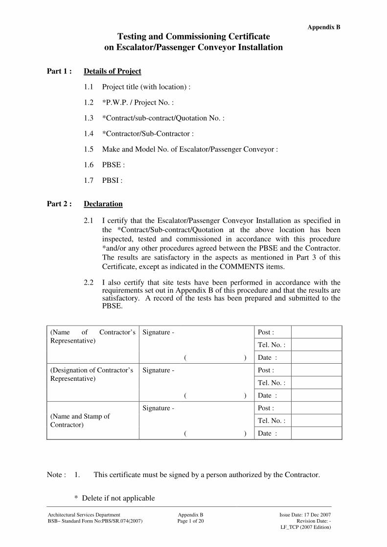
Appendix B
Architectural Services Department Appendix B Issue Date: 17 Dec 2007 BSB– Standard Form No:PBS/SR.074(2007) Page 1 of 20 Revision Date: - LF_TCP (2007 Edition)
Testing and Commissioning Certificate on Escalator/Passenger Conveyor Installation
Part 1 : Details of Project
1.1 Project title (with location) : 1.2 *P.W.P. / Project No. : 1.3 *Contract/sub-contract/Quotation No. : 1.4 *Contractor/Sub-Contractor : 1.5 Make and Model No. of Escalator/Passenger Conveyor : 1.6 PBSE : 1.7 PBSI :
Part 2 : Declaration
2.1 I certify that the Escalator/Passenger Conveyor Installation as specified in the *Contract/Sub-contract/Quotation at the above location has been inspected, tested and commissioned in accordance with this procedure *and/or any other procedures agreed between the PBSE and the Contractor. The results are satisfactory in the aspects as mentioned in Part 3 of this Certificate, except as indicated in the COMMENTS items.
2.2 I also certify that site tests have been performed in accordance with the
requirements set out in Appendix B of this procedure and that the results are satisfactory. A record of the tests has been prepared and submitted to the PBSE.
Signature - Post :
Tel. No. :
(Name of Contractor’s Representative)
( ) Date :
Signature - Post :
Tel. No. :
(Designation of Contractor’s Representative)
( ) Date :
Signature - Post :
Tel. No. : (Name and Stamp of Contractor)
( ) Date : Note : 1. This certificate must be signed by a person authorized by the Contractor. * Delete if not applicable
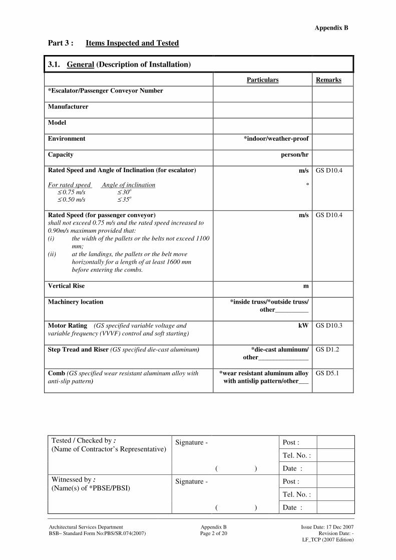
Appendix B
Signature - Post :
Tel. No. :
Tested / Checked by : (Name of Contractor’s Representative)
( ) Date :
Signature - Post :
Tel. No. :
Witnessed by : (Name(s) of *PBSE/PBSI)
( ) Date : Architectural Services Department Appendix B Issue Date: 17 Dec 2007 BSB– Standard Form No:PBS/SR.074(2007) Page 2 of 20 Revision Date: - LF_TCP (2007 Edition)
Part 3 : Items Inspected and Tested
3.1. General (Description of Installation)
Particulars Remarks
*Escalator/Passenger Conveyor Number
Manufacturer
Model
Environment
*indoor/weather-proof
Capacity
person/hr
Rated Speed and Angle of Inclination (for escalator) For rated speed Angle of inclination
≤ 0.75 m/s ≤ 30o ≤ 0.50 m/s ≤ 35o
m/s
o
GS D10.4
Rated Speed (for passenger conveyor) shall not exceed 0.75 m/s and the rated speed increased to 0.90m/s maximum provided that: (i) the width of the pallets or the belts not exceed 1100
mm; (ii) at the landings, the pallets or the belt move
horizontally for a length of at least 1600 mm before entering the combs.
m/s GS D10.4
Vertical Rise
m
Machinery location
*inside truss/*outside truss/ other__________
Motor Rating (GS specified variable voltage and variable frequency (VVVF) control and soft starting)
kW GS D10.3
Step Tread and Riser (GS specified die-cast aluminum)
*die-cast aluminum/ other_______________
GS D1.2
Comb (GS specified wear resistant aluminum alloy with anti-slip pattern)
*wear resistant aluminum alloy with antislip pattern/other___
GS D5.1
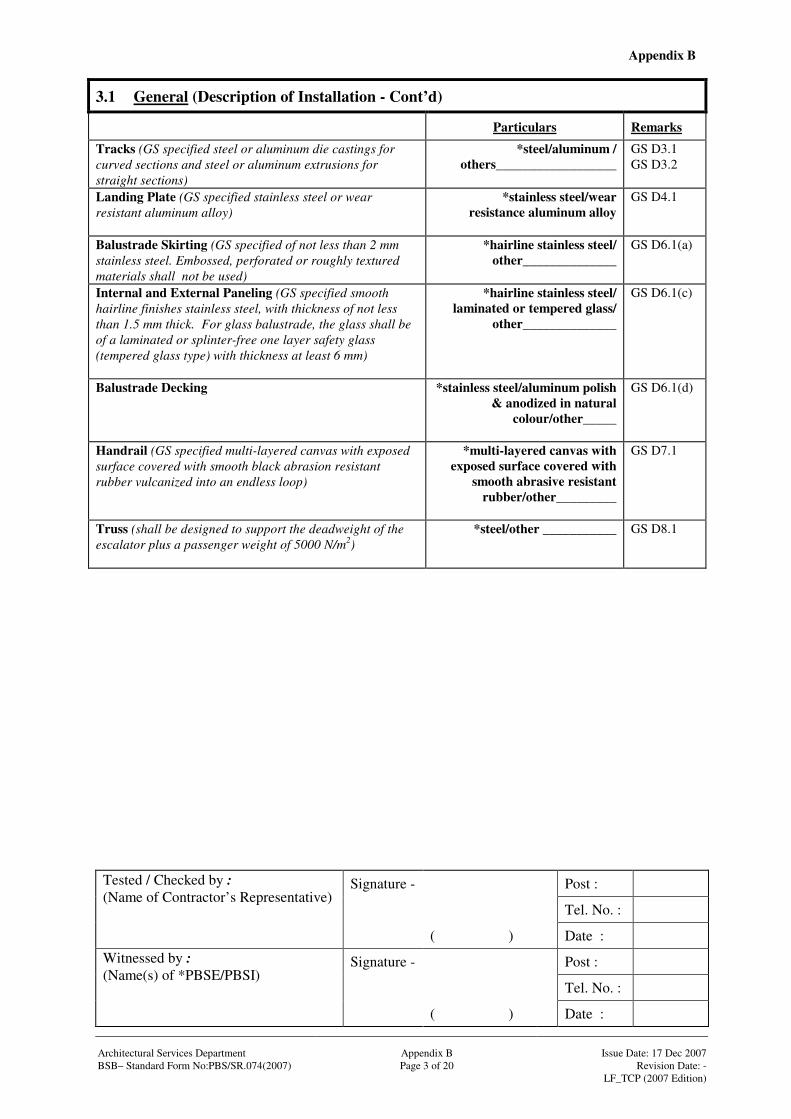
Appendix B
Signature - Post :
Tel. No. :
Tested / Checked by : (Name of Contractor’s Representative)
( ) Date :
Signature - Post :
Tel. No. :
Witnessed by : (Name(s) of *PBSE/PBSI)
( ) Date : Architectural Services Department Appendix B Issue Date: 17 Dec 2007 BSB– Standard Form No:PBS/SR.074(2007) Page 3 of 20 Revision Date: - LF_TCP (2007 Edition)
3.1 General (Description of Installation - Cont’d)
Particulars Remarks
Tracks (GS specified steel or aluminum die castings for curved sections and steel or aluminum extrusions for straight sections)
*steel/aluminum / others__________________
GS D3.1 GS D3.2
Landing Plate (GS specified stainless steel or wear resistant aluminum alloy)
*stainless steel/wear resistance aluminum alloy
GS D4.1
Balustrade Skirting (GS specified of not less than 2 mm stainless steel. Embossed, perforated or roughly textured materials shall not be used)
*hairline stainless steel/ other______________
GS D6.1(a)
Internal and External Paneling (GS specified smooth hairline finishes stainless steel, with thickness of not less than 1.5 mm thick. For glass balustrade, the glass shall be of a laminated or splinter-free one layer safety glass (tempered glass type) with thickness at least 6 mm)
*hairline stainless steel/ laminated or tempered glass/
other______________
GS D6.1(c)
Balustrade Decking
*stainless steel/aluminum polish & anodized in natural
colour/other_____
GS D6.1(d)
Handrail (GS specified multi-layered canvas with exposed surface covered with smooth black abrasion resistant rubber vulcanized into an endless loop)
*multi-layered canvas with exposed surface covered with
smooth abrasive resistant rubber/other_________
GS D7.1
Truss (shall be designed to support the deadweight of the escalator plus a passenger weight of 5000 N/m2)
*steel/other ___________
GS D8.1
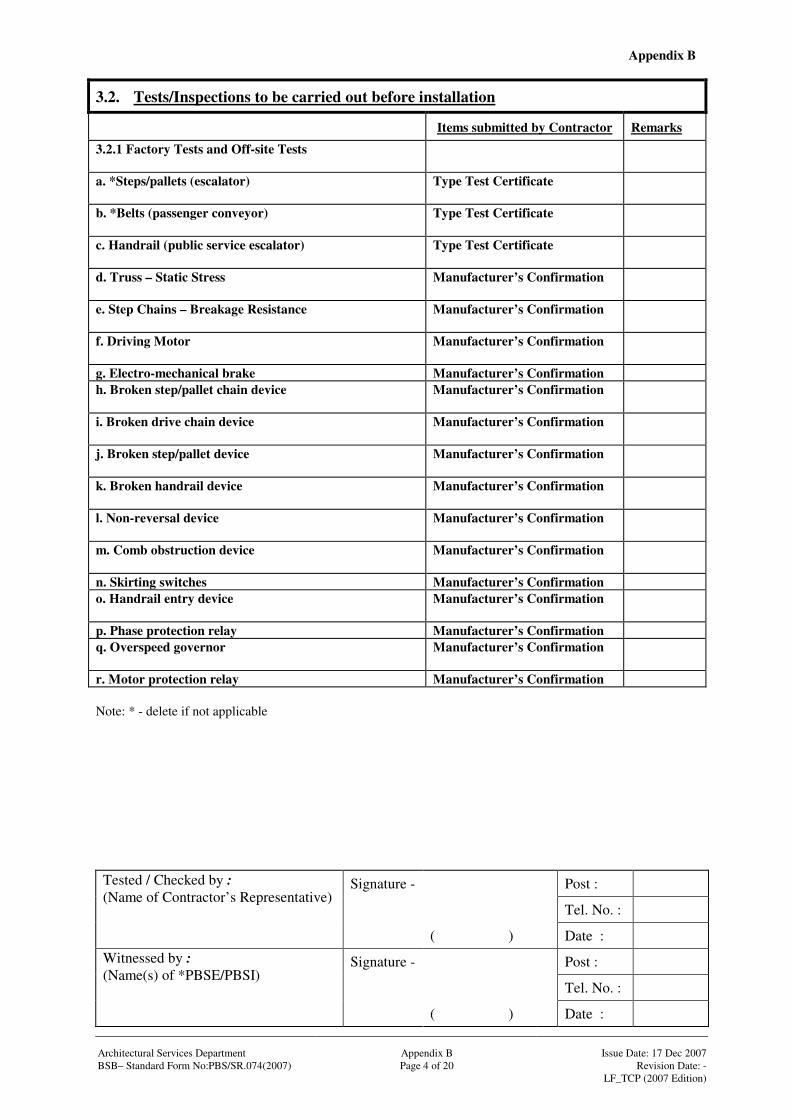
Appendix B
Signature - Post :
Tel. No. :
Tested / Checked by : (Name of Contractor’s Representative)
( ) Date :
Signature - Post :
Tel. No. :
Witnessed by : (Name(s) of *PBSE/PBSI)
( ) Date : Architectural Services Department Appendix B Issue Date: 17 Dec 2007 BSB– Standard Form No:PBS/SR.074(2007) Page 4 of 20 Revision Date: - LF_TCP (2007 Edition)
3.2. Tests/Inspections to be carried out before installation
Items submitted by Contractor Remarks
3.2.1 Factory Tests and Off-site Tests
a. *Steps/pallets (escalator)
Type Test Certificate
b. *Belts (passenger conveyor)
Type Test Certificate
c. Handrail (public service escalator)
Type Test Certificate
d. Truss – Static Stress
Manufacturer’s Confirmation
e. Step Chains – Breakage Resistance
Manufacturer’s Confirmation
f. Driving Motor
Manufacturer’s Confirmation
g. Electro-mechanical brake Manufacturer’s Confirmation h. Broken step/pallet chain device
Manufacturer’s Confirmation
i. Broken drive chain device
Manufacturer’s Confirmation
j. Broken step/pallet device
Manufacturer’s Confirmation
k. Broken handrail device
Manufacturer’s Confirmation
l. Non-reversal device
Manufacturer’s Confirmation
m. Comb obstruction device
Manufacturer’s Confirmation
n. Skirting switches Manufacturer’s Confirmation o. Handrail entry device
Manufacturer’s Confirmation
p. Phase protection relay Manufacturer’s Confirmation q. Overspeed governor
Manufacturer’s Confirmation
r. Motor protection relay Manufacturer’s Confirmation Note: * - delete if not applicable
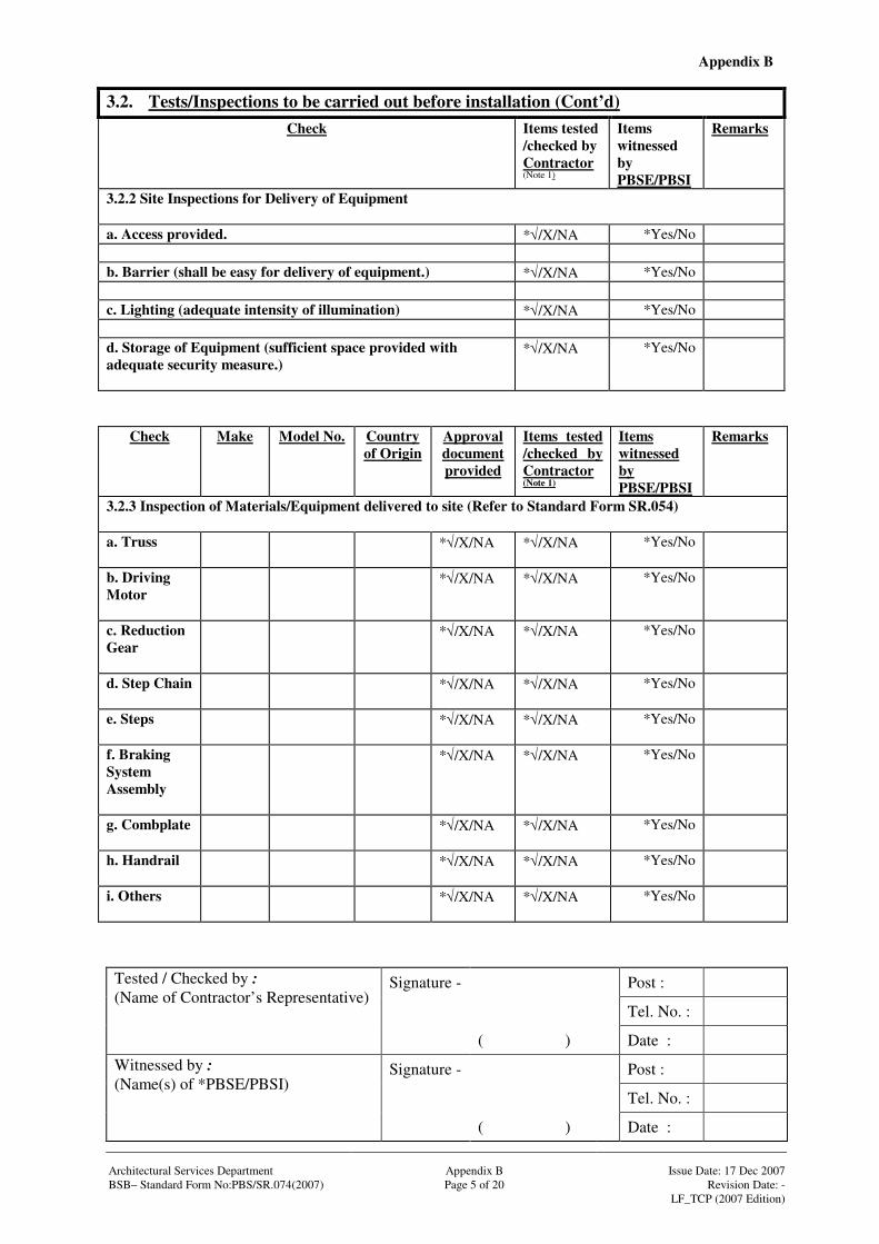
Appendix B
Signature - Post :
Tel. No. :
Tested / Checked by : (Name of Contractor’s Representative)
( ) Date :
Signature - Post :
Tel. No. :
Witnessed by : (Name(s) of *PBSE/PBSI)
( ) Date : Architectural Services Department Appendix B Issue Date: 17 Dec 2007 BSB– Standard Form No:PBS/SR.074(2007) Page 5 of 20 Revision Date: - LF_TCP (2007 Edition)
3.2. Tests/Inspections to be carried out before installation (Cont’d)
Check Items tested /checked by Contractor (Note 1)
Items witnessed by PBSE/PBSI
Remarks
3.2.2 Site Inspections for Delivery of Equipment a. Access provided. *√/X/NA *Yes/No b. Barrier (shall be easy for delivery of equipment.) *√/X/NA *Yes/No c. Lighting (adequate intensity of illumination) *√/X/NA *Yes/No d. Storage of Equipment (sufficient space provided with adequate security measure.)
*√/X/NA *Yes/No
Check Make Model No. Country of Origin
Approval document provided
Items tested /checked by Contractor (Note 1)
Items witnessed by PBSE/PBSI
Remarks
3.2.3 Inspection of Materials/Equipment delivered to site (Refer to Standard Form SR.054) a. Truss
*√/X/NA *√/X/NA *Yes/No
b. Driving Motor
*√/X/NA *√/X/NA *Yes/No
c. Reduction Gear
*√/X/NA *√/X/NA *Yes/No
d. Step Chain
*√/X/NA *√/X/NA *Yes/No
e. Steps
*√/X/NA *√/X/NA *Yes/No
f. Braking System Assembly
*√/X/NA *√/X/NA *Yes/No
g. Combplate
*√/X/NA *√/X/NA *Yes/No
h. Handrail
*√/X/NA *√/X/NA *Yes/No
i. Others
*√/X/NA *√/X/NA *Yes/No

Appendix B
Signature - Post :
Tel. No. :
Tested / Checked by : (Name of Contractor’s Representative)
( ) Date :
Signature - Post :
Tel. No. :
Witnessed by : (Name(s) of *PBSE/PBSI)
( ) Date : Architectural Services Department Appendix B Issue Date: 17 Dec 2007 BSB– Standard Form No:PBS/SR.074(2007) Page 6 of 20 Revision Date: - LF_TCP (2007 Edition)
3.2. Tests/Inspections to be carried out before installation (Cont’d)
Check Items tested /checked by Contractor (Note 1)
Items witnessed by PBSE/PBSI
Remarks
3.2.4 Escalator Pit Installation a. Dimensions (shall be in-lined with installation drawings.) *√/X/NA *Yes/No b. Finishes (shall be in-lined with installation drawings.) *√/X/NA *Yes/No c. Adequacy and accuracy of builder’s work provision *√/X/NA *Yes/No 3.2.5 Other tests/inspections for setting to work, safety and quality tests etc. required before commencing installation works
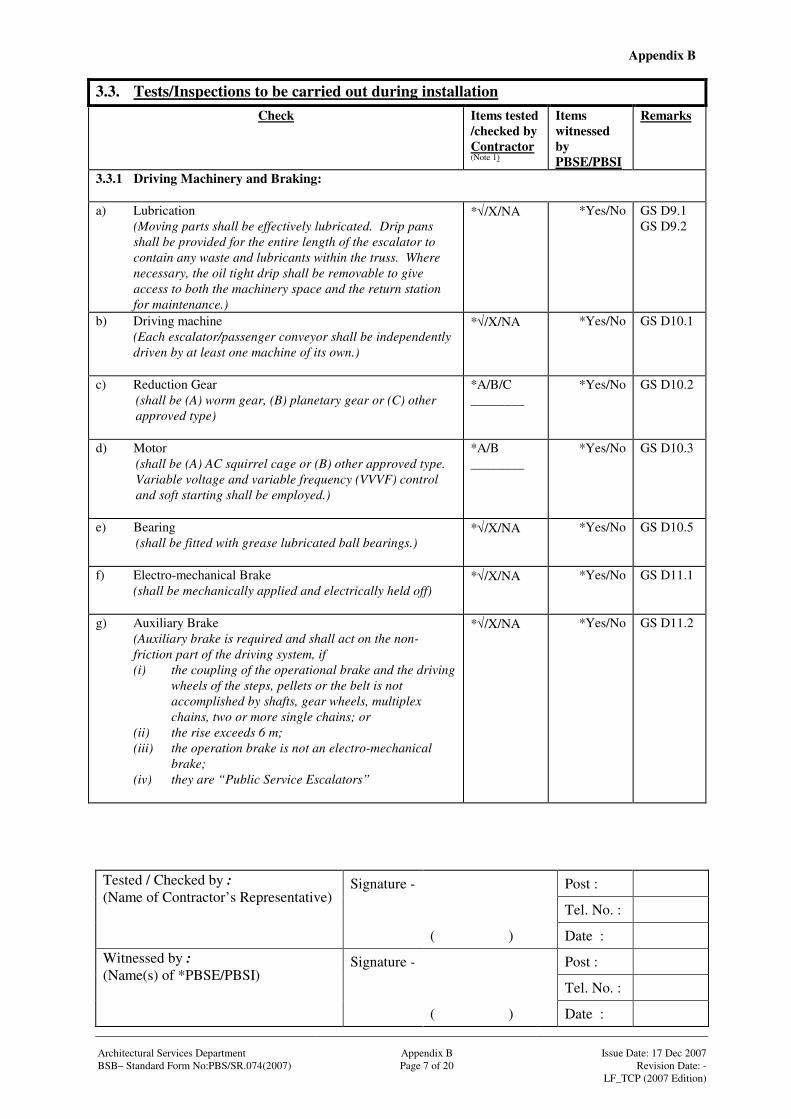
Appendix B
Signature - Post :
Tel. No. :
Tested / Checked by : (Name of Contractor’s Representative)
( ) Date :
Signature - Post :
Tel. No. :
Witnessed by : (Name(s) of *PBSE/PBSI)
( ) Date : Architectural Services Department Appendix B Issue Date: 17 Dec 2007 BSB– Standard Form No:PBS/SR.074(2007) Page 7 of 20 Revision Date: - LF_TCP (2007 Edition)
3.3. Tests/Inspections to be carried out during installation
Check Items tested /checked by Contractor (Note 1)
Items witnessed by PBSE/PBSI
Remarks
3.3.1 Driving Machinery and Braking: a) Lubrication
(Moving parts shall be effectively lubricated. Drip pans shall be provided for the entire length of the escalator to contain any waste and lubricants within the truss. Where necessary, the oil tight drip shall be removable to give access to both the machinery space and the return station for maintenance.)
*√/X/NA
*Yes/No GS D9.1 GS D9.2
b) Driving machine (Each escalator/passenger conveyor shall be independently driven by at least one machine of its own.)
*√/X/NA
*Yes/No GS D10.1
c) Reduction Gear (shall be (A) worm gear, (B) planetary gear or (C) other approved type)
*A/B/C ________
*Yes/No GS D10.2
d) Motor (shall be (A) AC squirrel cage or (B) other approved type. Variable voltage and variable frequency (VVVF) control and soft starting shall be employed.)
*A/B ________
*Yes/No GS D10.3
e) Bearing (shall be fitted with grease lubricated ball bearings.)
*√/X/NA
*Yes/No GS D10.5
f) Electro-mechanical Brake (shall be mechanically applied and electrically held off)
*√/X/NA
*Yes/No GS D11.1
g) Auxiliary Brake (Auxiliary brake is required and shall act on the non-friction part of the driving system, if (i) the coupling of the operational brake and the driving
wheels of the steps, pellets or the belt is not accomplished by shafts, gear wheels, multiplex chains, two or more single chains; or
(ii) the rise exceeds 6 m; (iii) the operation brake is not an electro-mechanical
brake; (iv) they are “Public Service Escalators”
*√/X/NA
*Yes/No GS D11.2

Appendix B
Signature - Post :
Tel. No. :
Tested / Checked by : (Name of Contractor’s Representative)
( ) Date :
Signature - Post :
Tel. No. :
Witnessed by : (Name(s) of *PBSE/PBSI)
( ) Date : Architectural Services Department Appendix B Issue Date: 17 Dec 2007 BSB– Standard Form No:PBS/SR.074(2007) Page 8 of 20 Revision Date: - LF_TCP (2007 Edition)
3.4. Functional Performance Tests Check Items tested
/checked by Contractor (Note 1)
Items witnessed by PBSE/PBSI
Remarks
3.4.1 *Steps/Pallets: a) Width (shall be 1000 mm unless otherwise specified)
mm *Yes/No GS D1.1
b) Depth (shall be 400 mm)
mm *Yes/No GS D1.5
c) Rise (shall be 240 mm)
mm *Yes/No GS D1.5
d) Clear height above step (shall be 2300 mm at all points)
mm *Yes/No GS D1.6
d) 25 mm width yellow lines (For escalator, yellow lines shall be marked on both sides and front of the leading /trailing edges of the steps with durable and wear resistant materials to show demarcation between comb and cleat. For passenger conveyor, yellow lines shall be marked on both sides of the pallets only)
*√/X/NA
*Yes/No GS D1.1
f) Flat steps for escalator (shall have at least a length of two complete steps i.e. 800mm at either end of the escalator traveling horizontally from the comb line)
*√/X/NA
*Yes/No GS D1.7
g) Rollers (each step/pallet shall be supported on four roller or synthetic material tyred ball bearing rollers, grease sealed for life)
*√/X/NA
*Yes/No GS D1.3
h) Step/Pallet Chain and Tracks (shall be made of high tensile steel links with hardened and ground pin)
*√/X/NA
*Yes/No GS D1.4 GS D2.1 GS D2.2 GS D2.3
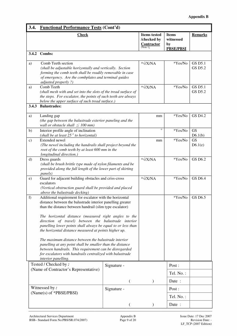
Appendix B
Signature - Post :
Tel. No. :
Tested / Checked by : (Name of Contractor’s Representative)
( ) Date :
Signature - Post :
Tel. No. :
Witnessed by : (Name(s) of *PBSE/PBSI)
( ) Date : Architectural Services Department Appendix B Issue Date: 17 Dec 2007 BSB– Standard Form No:PBS/SR.074(2007) Page 9 of 20 Revision Date: - LF_TCP (2007 Edition)
3.4. Functional Performance Tests (Cont’d)
Check Items tested /checked by Contractor (Note 1)
Items witnessed by PBSE/PBSI
Remarks
3.4.2 Combs: a) Comb Teeth section
(shall be adjustable horizontally and vertically. Section forming the comb teeth shall be readily removable in case of emergency. Are the combplates and terminal guides adjusted properly ?)
*√/X/NA
*Yes/No GS D5.1 GS D5.2
a) Comb Teeth (shall mesh with and set into the slots of the tread surface of the steps. For escalator, the points of such teeth are always below the upper surface of such tread surface.)
*√/X/NA
*Yes/No GS D5.1 GS D5.2
3.4.3 Balustrades: a) Landing gap (the gap between the balustrade exterior paneling and the
wall or obstacle shall 100 mm)
mm *Yes/No GS D4.2
b) Interior profile angle of inclination (shall be at least 25 o to horizontal)
o *Yes/No GS D6.1(b)
c) Extended newel (The newel including the handrails shall project beyond the root of the comb teeth by at least 600 mm in the longitudinal direction.)
mm *Yes/No GS D6.1(e)
d) Dress guards (shall be brush brittle type made of nylon filaments and be provided along the full length of the lower part of skirting panels)
*√/X/NA
*Yes/No GS D6.2
e) Guard for adjacent building obstacles and criss-cross escalators (Vertical obstruction guard shall be provided and placed above the balustrade decking)
*√/X/NA
*Yes/No GS D6.4
f) Additional requirement for escalator with the horizontal distance between the balustrade interior panelling greater than the distance between handrail (slim type escalator) The horizontal distance (measured right angles to the direction of travel) between the balustrade interior panelling lower points shall always be equal to or less than the horizontal distance measured at points higher up. The maximum distance between the balustrade interior panelling at any point shall be smaller than the distance between handrails. This requirement can be disregarded for escalators with handrails centralized with balustrade interior panelling.
*Yes/No GS D6.5
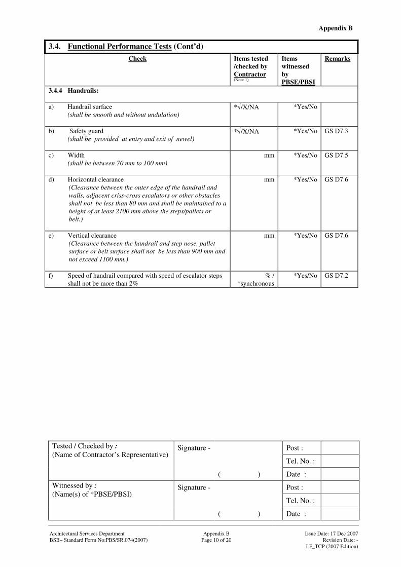
Appendix B
Signature - Post :
Tel. No. :
Tested / Checked by : (Name of Contractor’s Representative)
( ) Date :
Signature - Post :
Tel. No. :
Witnessed by : (Name(s) of *PBSE/PBSI)
( ) Date : Architectural Services Department Appendix B Issue Date: 17 Dec 2007 BSB– Standard Form No:PBS/SR.074(2007) Page 10 of 20 Revision Date: - LF_TCP (2007 Edition)
3.4. Functional Performance Tests (Cont’d)
Check Items tested /checked by Contractor (Note 1)
Items witnessed by PBSE/PBSI
Remarks
3.4.4 Handrails: a) Handrail surface
(shall be smooth and without undulation)
*√/X/NA
*Yes/No
b) Safety guard (shall be provided at entry and exit of newel)
*√/X/NA
*Yes/No GS D7.3
c) Width (shall be between 70 mm to 100 mm)
mm *Yes/No GS D7.5
d) Horizontal clearance (Clearance between the outer edge of the handrail and walls, adjacent criss-cross escalators or other obstacles shall not be less than 80 mm and shall be maintained to a height of at least 2100 mm above the steps/pallets or belt.)
mm *Yes/No GS D7.6
e) Vertical clearance (Clearance between the handrail and step nose, pallet surface or belt surface shall not be less than 900 mm and not exceed 1100 mm.)
mm *Yes/No GS D7.6
f) Speed of handrail compared with speed of escalator steps shall not be more than 2%
% / *synchronous
*Yes/No GS D7.2

Appendix B
Signature - Post :
Tel. No. :
Tested / Checked by : (Name of Contractor’s Representative)
( ) Date :
Signature - Post :
Tel. No. :
Witnessed by : (Name(s) of *PBSE/PBSI)
( ) Date : Architectural Services Department Appendix B Issue Date: 17 Dec 2007 BSB– Standard Form No:PBS/SR.074(2007) Page 11 of 20 Revision Date: - LF_TCP (2007 Edition)
3.4. Functional Performance Tests (Cont’d)
Check Items tested /checked by Contractor (Note 1)
Items witnessed by PBSE/PBSI
Remarks
3.4.5 Brakes: a) Electro-mechanical Brake
(shall be mechanically applied and electrically held off) (Has the brake been examined and found to be mechanically applied and electrically held off of sufficient capacity to efficiently bring the escalator/passenger conveyor to rest with uniform deceleration when travelling at full contract speed in either direction)
*√/X/NA
*Yes/No GS D11.1
b) Auxiliary Brake (Has the brake been examined and found to be in order?)
(Auxiliary brake is required and shall act on the non-friction part of the driving system, if (i) the coupling of the operational brake and the driving
wheels of the steps, pellets or the belt is not accomplished by shafts, gear wheels, multiplex chains, two or more single chains; or
(ii) the rise exceeds 6 m; (iii) the operation brake is not an electro-mechanical
brake; (iv) they are “Public Service Escalators”
*√/X/NA
*Yes/No GS D11.2
c) Has the brake been tested at *unloaded / *full load *Up *down condition, and the stopping distances for *unloaded / *full load *Upward *Downward moving escalators within the range: For rated speed Stopping distance between 0.50 m/s min. 0.20 m & max 1.00 m
0.65 m/s min, 0.30 m & max 1.30 m 0.75 m/s min. 0.35 m & max 1.50 m)
*√/X/NA mm
*Yes/No GS D11.4
d) Has the brake been tested at *unloaded / *full load condition, and the stopping distances for unloaded and loaded passenger conveyors within the range: For rated speed Stopping distance between 0.50 m/s min. 0.20 m & max 1.00 m
0.65 m/s min, 0.30 m & max 1.30 m 0.75 m/s min. 0.35 m & max 1.50 m 0.90 m/s min. 0.40 m & max 1.70 m
*√/X/NA mm
*Yes/No GS D11.4
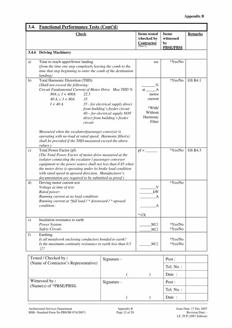
Appendix B
Signature - Post :
Tel. No. :
Tested / Checked by : (Name of Contractor’s Representative)
( ) Date :
Signature - Post :
Tel. No. :
Witnessed by : (Name(s) of *PBSE/PBSI)
( ) Date : Architectural Services Department Appendix B Issue Date: 17 Dec 2007 BSB– Standard Form No:PBS/SR.074(2007) Page 12 of 20 Revision Date: - LF_TCP (2007 Edition)
3.4. Functional Performance Tests (Cont’d)
Check Items tested /checked by Contractor (Note 1)
Items witnessed by PBSE/PBSI
Remarks
3.4.6 Driving Machinery a) Time to reach upper/lower landing (from the time one step completely leaving the comb to the
time that step beginning to enter the comb of the destination landing)
sec
*Yes/No
b) Total Harmonic Distortion (THD) (Shall not exceed the following: Circuit Fundamental Current of Motor Drive Max THD % 80A I < 400A 22.5 40 A I < 80A 35
I < 40 A 35 - for electrical supply direct from building’s feeder circuit 40 – for electrical supply NOT direct from building’s feeder circuit
Measured when the escalator/passenger conveyor is operating with no-load at rated speed. Harmonic filter(s) shall be provided if the THD measured exceed the above values.)
_______% at _____A
motor current
*With/
Without Harmonic
Filter
*Yes/No GS B4.1
c) Total Power Factor (pf) (The Total Power Factor of motor drive measured at the
isolator connecting the escalator / passenger conveyor equipment to the power source shall not less than 0.85 when the motor drive is operating under its brake load condition with rated speed in upward direction. Manufacturer’s documentation are required to be submitted as proof.)
pf = ______ *Yes/No GS B4.3
d) Driving motor current test Voltage at time of test: Rated power: Running current at no load condition: Running current at *full load / * downward / * upward condition:
________V _______kW ________A
________A
*√/X
*Yes/No
e) Insulation resistance to earth Power System:
Safety Circuit:
______M______M
*Yes/No *Yes/No
f) Earthing Is all metalwork enclosing conductors bonded to earth? Is the maximum continuity resistance to earth less than 0.5
?
______M
*Yes/No *Yes/No
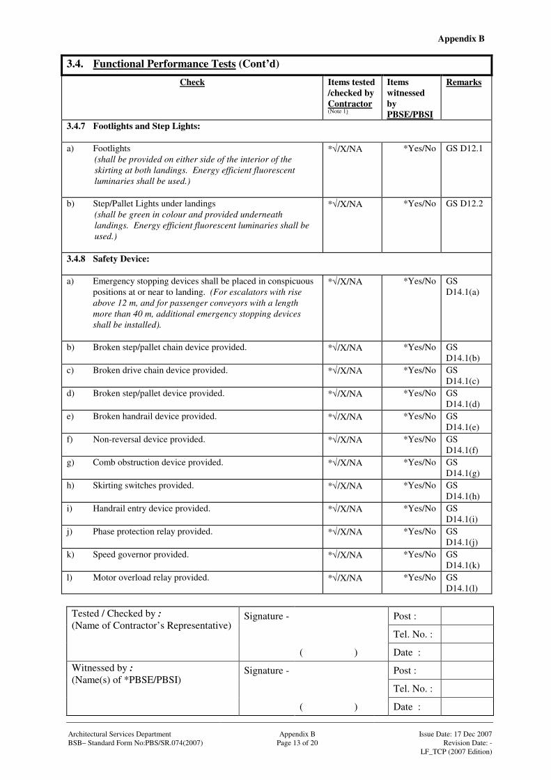
Appendix B
Signature - Post :
Tel. No. :
Tested / Checked by : (Name of Contractor’s Representative)
( ) Date :
Signature - Post :
Tel. No. :
Witnessed by : (Name(s) of *PBSE/PBSI)
( ) Date : Architectural Services Department Appendix B Issue Date: 17 Dec 2007 BSB– Standard Form No:PBS/SR.074(2007) Page 13 of 20 Revision Date: - LF_TCP (2007 Edition)
3.4. Functional Performance Tests (Cont’d)
Check Items tested /checked by Contractor (Note 1)
Items witnessed by PBSE/PBSI
Remarks
3.4.7 Footlights and Step Lights: a) Footlights
(shall be provided on either side of the interior of the skirting at both landings. Energy efficient fluorescent luminaries shall be used.)
*√/X/NA
*Yes/No GS D12.1
b) Step/Pallet Lights under landings (shall be green in colour and provided underneath landings. Energy efficient fluorescent luminaries shall be used.)
*√/X/NA
*Yes/No GS D12.2
3.4.8 Safety Device: a) Emergency stopping devices shall be placed in conspicuous
positions at or near to landing. (For escalators with rise above 12 m, and for passenger conveyors with a length more than 40 m, additional emergency stopping devices shall be installed).
*√/X/NA
*Yes/No GS D14.1(a)
b) Broken step/pallet chain device provided.
*√/X/NA
*Yes/No GS D14.1(b)
c) Broken drive chain device provided.
*√/X/NA
*Yes/No GS D14.1(c)
d) Broken step/pallet device provided.
*√/X/NA
*Yes/No GS D14.1(d)
e) Broken handrail device provided.
*√/X/NA
*Yes/No GS D14.1(e)
f) Non-reversal device provided.
*√/X/NA
*Yes/No GS D14.1(f)
g) Comb obstruction device provided.
*√/X/NA
*Yes/No GS D14.1(g)
h) Skirting switches provided.
*√/X/NA
*Yes/No GS D14.1(h)
i) Handrail entry device provided.
*√/X/NA
*Yes/No GS D14.1(i)
j) Phase protection relay provided.
*√/X/NA
*Yes/No GS D14.1(j)
k) Speed governor provided.
*√/X/NA
*Yes/No GS D14.1(k)
l) Motor overload relay provided. *√/X/NA *Yes/No GS D14.1(l)
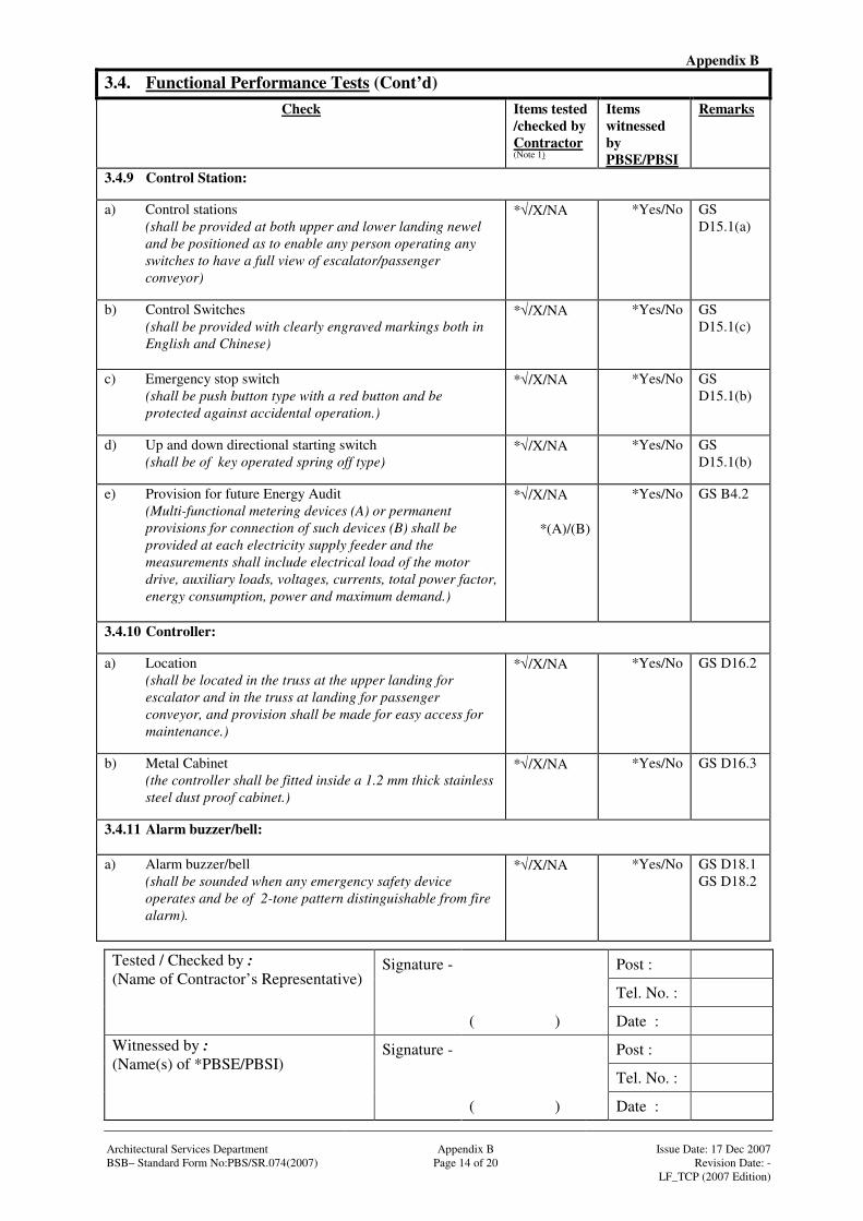
Appendix B
Signature - Post :
Tel. No. :
Tested / Checked by : (Name of Contractor’s Representative)
( ) Date :
Signature - Post :
Tel. No. :
Witnessed by : (Name(s) of *PBSE/PBSI)
( ) Date : Architectural Services Department Appendix B Issue Date: 17 Dec 2007 BSB– Standard Form No:PBS/SR.074(2007) Page 14 of 20 Revision Date: - LF_TCP (2007 Edition)
3.4. Functional Performance Tests (Cont’d)
Check Items tested /checked by Contractor (Note 1)
Items witnessed by PBSE/PBSI
Remarks
3.4.9 Control Station: a) Control stations
(shall be provided at both upper and lower landing newel and be positioned as to enable any person operating any switches to have a full view of escalator/passenger conveyor)
*√/X/NA
*Yes/No GS D15.1(a)
b) Control Switches (shall be provided with clearly engraved markings both in English and Chinese)
*√/X/NA
*Yes/No GS D15.1(c)
c) Emergency stop switch (shall be push button type with a red button and be protected against accidental operation.)
*√/X/NA
*Yes/No GS D15.1(b)
d) Up and down directional starting switch (shall be of key operated spring off type)
*√/X/NA
*Yes/No GS D15.1(b)
e) Provision for future Energy Audit (Multi-functional metering devices (A) or permanent provisions for connection of such devices (B) shall be provided at each electricity supply feeder and the measurements shall include electrical load of the motor drive, auxiliary loads, voltages, currents, total power factor, energy consumption, power and maximum demand.)
*√/X/NA
*(A)/(B)
*Yes/No GS B4.2
3.4.10 Controller: a) Location (shall be located in the truss at the upper landing for
escalator and in the truss at landing for passenger conveyor, and provision shall be made for easy access for maintenance.)
*√/X/NA
*Yes/No GS D16.2
b) Metal Cabinet (the controller shall be fitted inside a 1.2 mm thick stainless steel dust proof cabinet.)
*√/X/NA
*Yes/No GS D16.3
3.4.11 Alarm buzzer/bell: a) Alarm buzzer/bell
(shall be sounded when any emergency safety device operates and be of 2-tone pattern distinguishable from fire alarm).
*√/X/NA
*Yes/No GS D18.1 GS D18.2
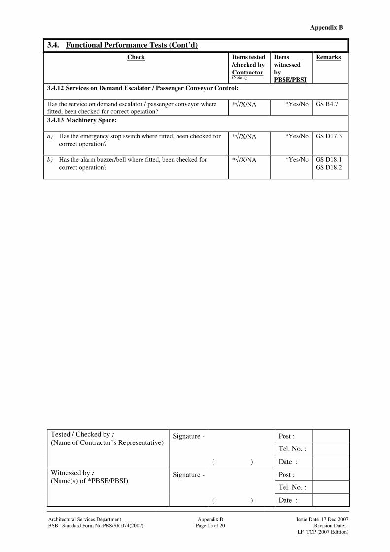
Appendix B
Signature - Post :
Tel. No. :
Tested / Checked by : (Name of Contractor’s Representative)
( ) Date :
Signature - Post :
Tel. No. :
Witnessed by : (Name(s) of *PBSE/PBSI)
( ) Date : Architectural Services Department Appendix B Issue Date: 17 Dec 2007 BSB– Standard Form No:PBS/SR.074(2007) Page 15 of 20 Revision Date: - LF_TCP (2007 Edition)
3.4. Functional Performance Tests (Cont’d)
Check Items tested /checked by Contractor (Note 1)
Items witnessed by PBSE/PBSI
Remarks
3.4.12 Services on Demand Escalator / Passenger Conveyor Control: Has the service on demand escalator / passenger conveyor where fitted, been checked for correct operation?
*√/X/NA
*Yes/No GS B4.7
3.4.13 Machinery Space: a) Has the emergency stop switch where fitted, been checked for
correct operation?
*√/X/NA
*Yes/No GS D17.3
b) Has the alarm buzzer/bell where fitted, been checked for correct operation?
*√/X/NA
*Yes/No GS D18.1 GS D18.2
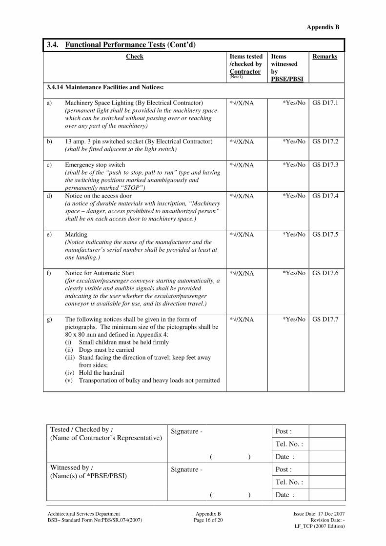
Appendix B
Signature - Post :
Tel. No. :
Tested / Checked by : (Name of Contractor’s Representative)
( ) Date :
Signature - Post :
Tel. No. :
Witnessed by : (Name(s) of *PBSE/PBSI)
( ) Date : Architectural Services Department Appendix B Issue Date: 17 Dec 2007 BSB– Standard Form No:PBS/SR.074(2007) Page 16 of 20 Revision Date: - LF_TCP (2007 Edition)
3.4. Functional Performance Tests (Cont’d)
Check Items tested /checked by Contractor (Note1)
Items witnessed by PBSE/PBSI
Remarks
3.4.14 Maintenance Facilities and Notices: a) Machinery Space Lighting (By Electrical Contractor)
(permanent light shall be provided in the machinery space which can be switched without passing over or reaching over any part of the machinery)
*√/X/NA
*Yes/No GS D17.1
b) 13 amp. 3 pin switched socket (By Electrical Contractor) (shall be fitted adjacent to the light switch)
*√/X/NA
*Yes/No GS D17.2
c) Emergency stop switch (shall be of the “push-to-stop, pull-to-run” type and having
the switching positions marked unambiguously and permanently marked “STOP”)
*√/X/NA
*Yes/No GS D17.3
d) Notice on the access door (a notice of durable materials with inscription, “Machinery space – danger, access prohibited to unauthorized person” shall be on each access door to machinery space.)
*√/X/NA
*Yes/No GS D17.4
e) Marking (Notice indicating the name of the manufacturer and the manufacturer’s serial number shall be provided at least at one landing.)
*√/X/NA
*Yes/No GS D17.5
f) Notice for Automatic Start (for escalator/passenger conveyor starting automatically, a clearly visible and audible signals shall be provided indicating to the user whether the escalator/passenger conveyor is available for use, and its direction travel.)
*√/X/NA
*Yes/No GS D17.6
g) The following notices shall be given in the form of pictographs. The minimum size of the pictographs shall be 80 x 80 mm and defined in Appendix 4: (i) Small children must be held firmly (ii) Dogs must be carried (iii) Stand facing the direction of travel; keep feet away
from sides; (iv) Hold the handrail (v) Transportation of bulky and heavy loads not permitted
*√/X/NA
*Yes/No GS D17.7
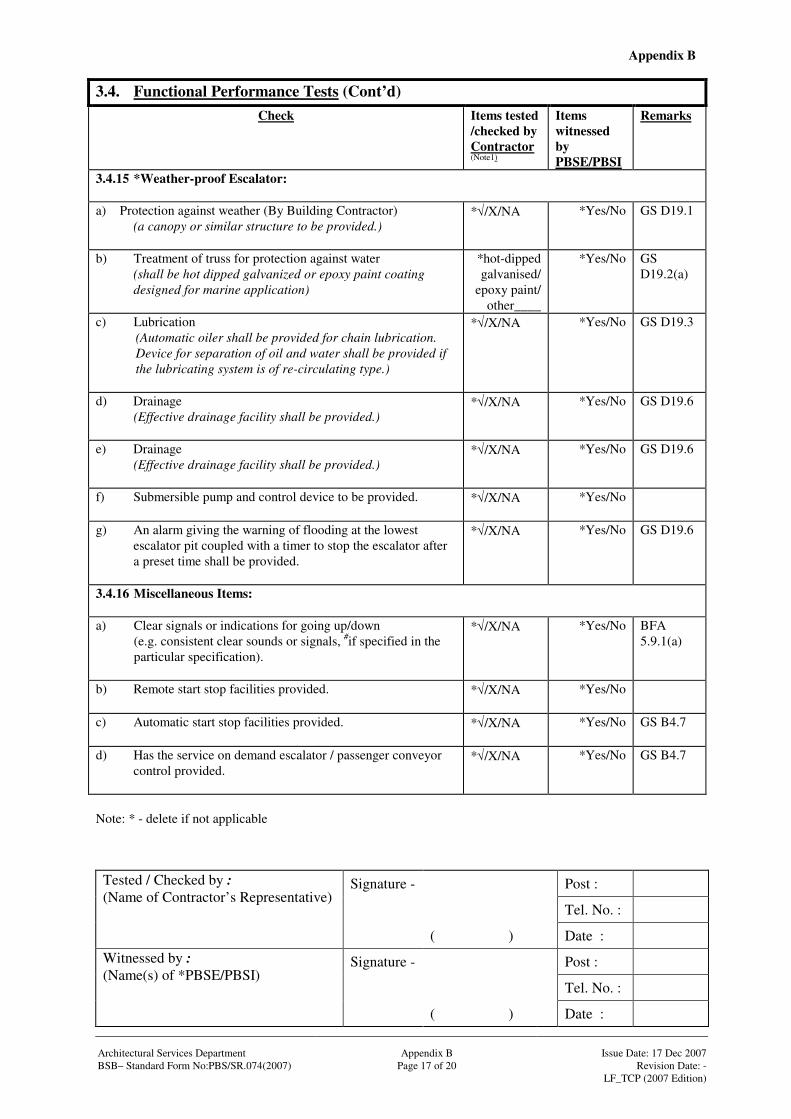
Appendix B
Signature - Post :
Tel. No. :
Tested / Checked by : (Name of Contractor’s Representative)
( ) Date :
Signature - Post :
Tel. No. :
Witnessed by : (Name(s) of *PBSE/PBSI)
( ) Date : Architectural Services Department Appendix B Issue Date: 17 Dec 2007 BSB– Standard Form No:PBS/SR.074(2007) Page 17 of 20 Revision Date: - LF_TCP (2007 Edition)
3.4. Functional Performance Tests (Cont’d)
Check Items tested /checked by Contractor (Note1)
Items witnessed by PBSE/PBSI
Remarks
3.4.15 *Weather-proof Escalator: a) Protection against weather (By Building Contractor)
(a canopy or similar structure to be provided.)
*√/X/NA
*Yes/No GS D19.1
b) Treatment of truss for protection against water (shall be hot dipped galvanized or epoxy paint coating
designed for marine application)
*hot-dipped galvanised/
epoxy paint/ other____
*Yes/No GS D19.2(a)
c) Lubrication (Automatic oiler shall be provided for chain lubrication. Device for separation of oil and water shall be provided if the lubricating system is of re-circulating type.)
*√/X/NA
*Yes/No GS D19.3
d) Drainage (Effective drainage facility shall be provided.)
*√/X/NA
*Yes/No GS D19.6
e) Drainage (Effective drainage facility shall be provided.)
*√/X/NA
*Yes/No GS D19.6
f) Submersible pump and control device to be provided.
*√/X/NA
*Yes/No
g) An alarm giving the warning of flooding at the lowest escalator pit coupled with a timer to stop the escalator after a preset time shall be provided.
*√/X/NA
*Yes/No GS D19.6
3.4.16 Miscellaneous Items: a) Clear signals or indications for going up/down
(e.g. consistent clear sounds or signals, #if specified in the particular specification).
*√/X/NA
*Yes/No BFA 5.9.1(a)
b) Remote start stop facilities provided.
*√/X/NA
*Yes/No
c) Automatic start stop facilities provided.
*√/X/NA
*Yes/No GS B4.7
d) Has the service on demand escalator / passenger conveyor control provided.
*√/X/NA
*Yes/No GS B4.7
Note: * - delete if not applicable
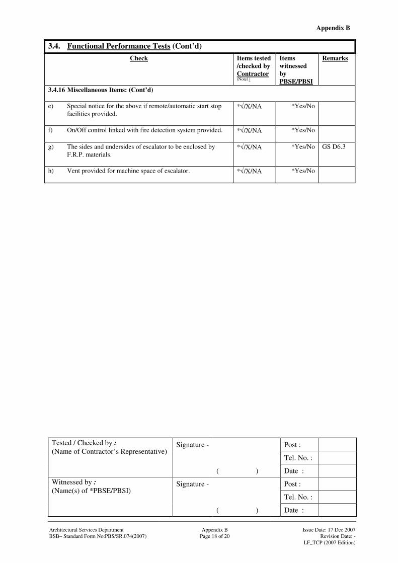
Appendix B
Signature - Post :
Tel. No. :
Tested / Checked by : (Name of Contractor’s Representative)
( ) Date :
Signature - Post :
Tel. No. :
Witnessed by : (Name(s) of *PBSE/PBSI)
( ) Date : Architectural Services Department Appendix B Issue Date: 17 Dec 2007 BSB– Standard Form No:PBS/SR.074(2007) Page 18 of 20 Revision Date: - LF_TCP (2007 Edition)
3.4. Functional Performance Tests (Cont’d)
Check Items tested /checked by Contractor (Note1)
Items witnessed by PBSE/PBSI
Remarks
3.4.16 Miscellaneous Items: (Cont’d) e) Special notice for the above if remote/automatic start stop
facilities provided.
*√/X/NA
*Yes/No
f) On/Off control linked with fire detection system provided.
*√/X/NA
*Yes/No
g) The sides and undersides of escalator to be enclosed by F.R.P. materials.
*√/X/NA
*Yes/No GS D6.3
h) Vent provided for machine space of escalator.
*√/X/NA
*Yes/No
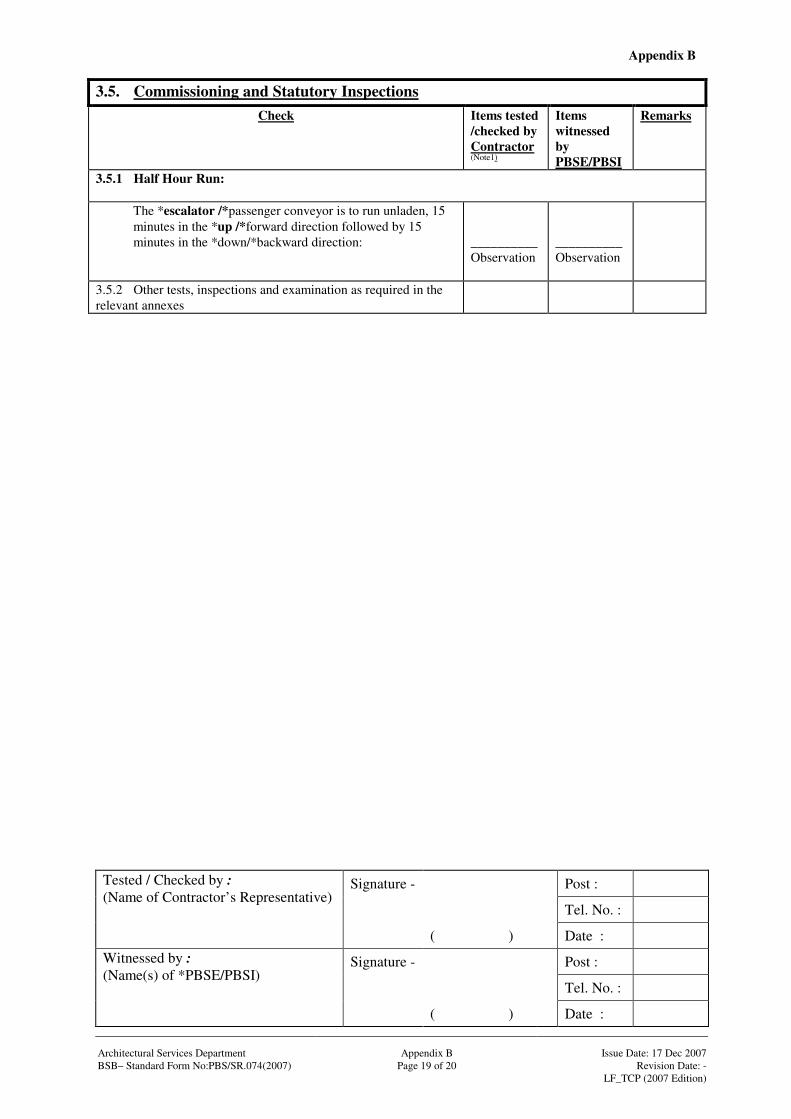
Appendix B
Signature - Post :
Tel. No. :
Tested / Checked by : (Name of Contractor’s Representative)
( ) Date :
Signature - Post :
Tel. No. :
Witnessed by : (Name(s) of *PBSE/PBSI)
( ) Date : Architectural Services Department Appendix B Issue Date: 17 Dec 2007 BSB– Standard Form No:PBS/SR.074(2007) Page 19 of 20 Revision Date: - LF_TCP (2007 Edition)
3.5. Commissioning and Statutory Inspections Check Items tested
/checked by Contractor (Note1)
Items witnessed by PBSE/PBSI
Remarks
3.5.1 Half Hour Run:
The *escalator /*passenger conveyor is to run unladen, 15 minutes in the *up /*forward direction followed by 15 minutes in the *down/*backward direction:
__________Observation
__________Observation
3.5.2 Other tests, inspections and examination as required in the relevant annexes
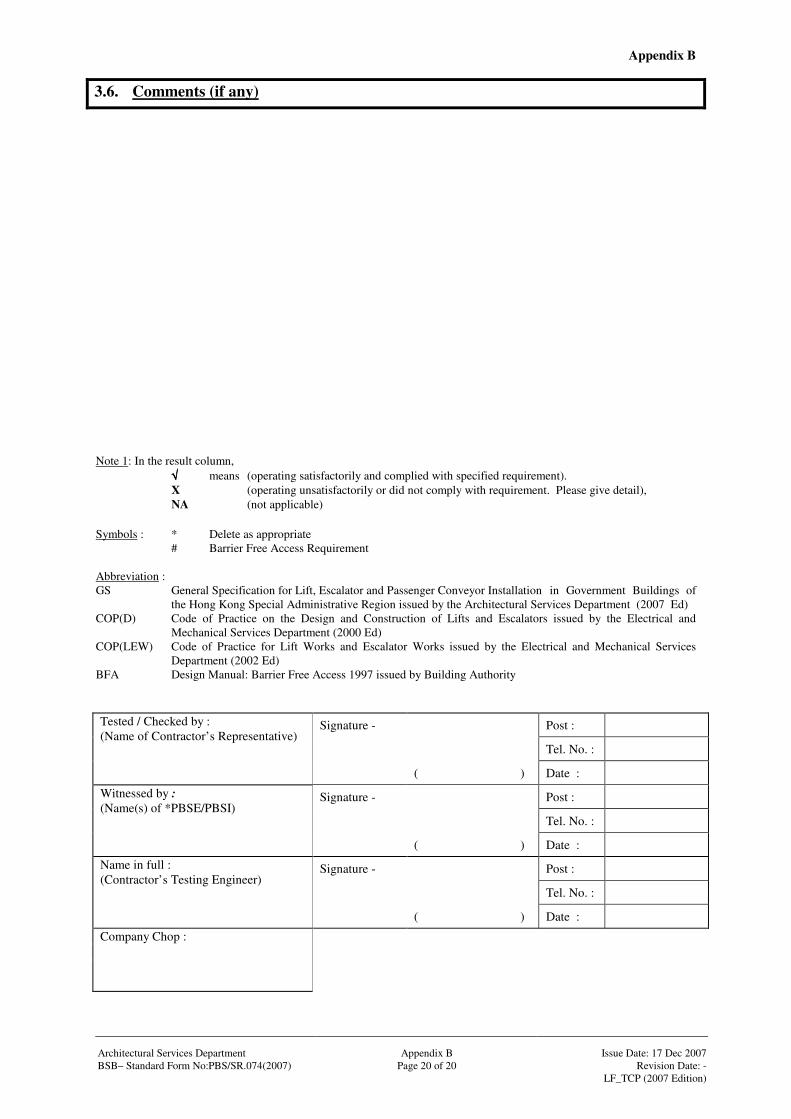
Appendix B
Architectural Services Department Appendix B Issue Date: 17 Dec 2007 BSB– Standard Form No:PBS/SR.074(2007) Page 20 of 20 Revision Date: - LF_TCP (2007 Edition)
3.6. Comments (if any)
Note 1: In the result column, √√√√ means (operating satisfactorily and complied with specified requirement). X (operating unsatisfactorily or did not comply with requirement. Please give detail), NA (not applicable) Symbols : * Delete as appropriate # Barrier Free Access Requirement Abbreviation : GS General Specification for Lift, Escalator and Passenger Conveyor Installation in Government Buildings of
the Hong Kong Special Administrative Region issued by the Architectural Services Department (2007 Ed) COP(D) Code of Practice on the Design and Construction of Lifts and Escalators issued by the Electrical and
Mechanical Services Department (2000 Ed) COP(LEW) Code of Practice for Lift Works and Escalator Works issued by the Electrical and Mechanical Services
Department (2002 Ed) BFA Design Manual: Barrier Free Access 1997 issued by Building Authority
Signature - Post :
Tel. No. :
Tested / Checked by : (Name of Contractor’s Representative)
( ) Date :
Signature - Post :
Tel. No. :
Witnessed by : (Name(s) of *PBSE/PBSI)
( ) Date :
Signature - Post :
Tel. No. :
Name in full : (Contractor’s Testing Engineer)
( ) Date :
Company Chop :
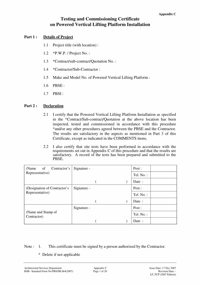
Appendix C
Architectural Services Department Appendix C Issue Date: 17 Dec 2007 BSB– Standard Form No:PBS/SR.064(2007) Page 1 of 20 Revision Date: - LF_TCP (2007 Edition)
Testing and Commissioning Certificate on Powered Vertical Lifting Platform Installation
Part 1 : Details of Project
1.1 Project title (with location) : 1.2 *P.W.P. / Project No. : 1.3 *Contract/sub-contract/Quotation No. : 1.4 *Contractor/Sub-Contractor : 1.5 Make and Model No. of Powered Vertical Lifting Platform : 1.6 PBSE : 1.7 PBSI :
Part 2 : Declaration
2.1 I certify that the Powered Vertical Lifting Platform Installation as specified in the *Contract/Sub-contract/Quotation at the above location has been inspected, tested and commissioned in accordance with this procedure *and/or any other procedures agreed between the PBSE and the Contractor. The results are satisfactory in the aspects as mentioned in Part 3 of this Certificate, except as indicated in the COMMENTS items.
2.2 I also certify that site tests have been performed in accordance with the
requirements set out in Appendix C of this procedure and that the results are satisfactory. A record of the tests has been prepared and submitted to the PBSE.
Signature - Post :
Tel. No. :
(Name of Contractor’s Representative)
( ) Date :
Signature - Post :
Tel. No. :
(Designation of Contractor’s Representative)
( ) Date :
Signature - Post :
Tel. No. : (Name and Stamp of Contractor)
( ) Date : Note : 1. This certificate must be signed by a person authorized by the Contractor. * Delete if not applicable
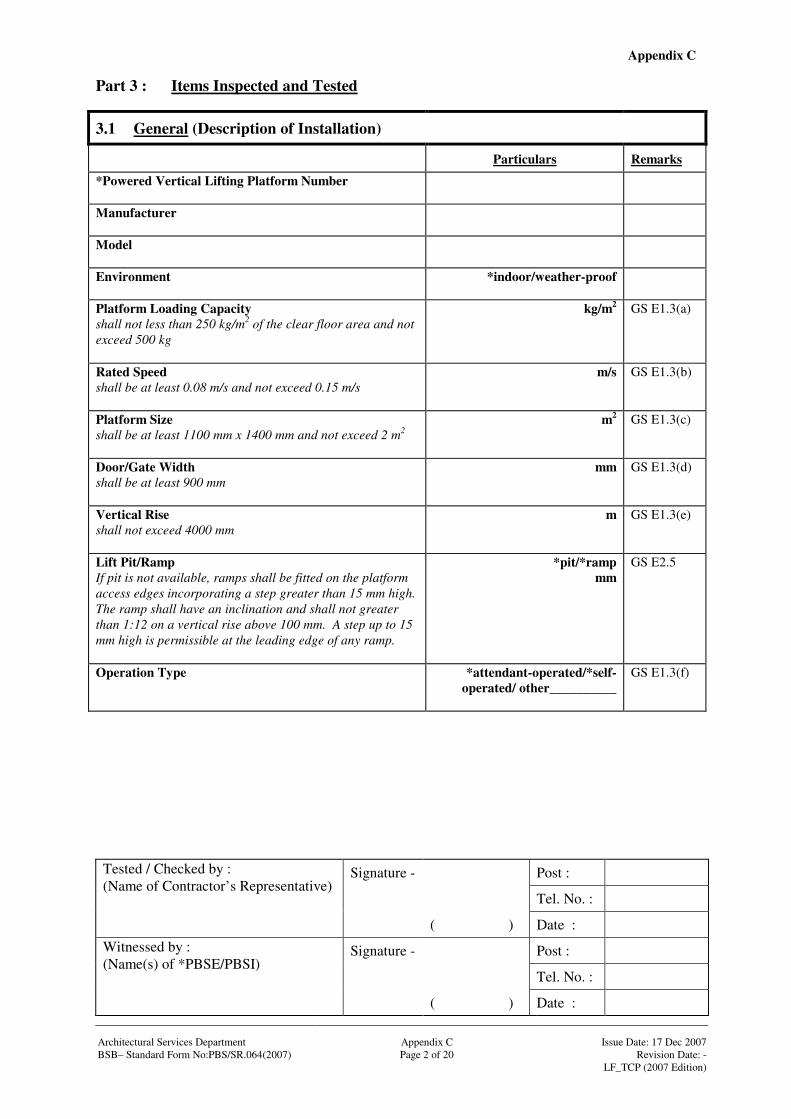
Appendix C
Signature - Post :
Tel. No. :
Tested / Checked by : (Name of Contractor’s Representative)
( ) Date :
Signature - Post :
Tel. No. :
Witnessed by : (Name(s) of *PBSE/PBSI)
( ) Date : Architectural Services Department Appendix C Issue Date: 17 Dec 2007 BSB– Standard Form No:PBS/SR.064(2007) Page 2 of 20 Revision Date: - LF_TCP (2007 Edition)
Part 3 : Items Inspected and Tested
3.1 General (Description of Installation)
Particulars Remarks
*Powered Vertical Lifting Platform Number
Manufacturer
Model
Environment
*indoor/weather-proof
Platform Loading Capacity shall not less than 250 kg/m2 of the clear floor area and not exceed 500 kg
kg/m2 GS E1.3(a)
Rated Speed shall be at least 0.08 m/s and not exceed 0.15 m/s
m/s GS E1.3(b)
Platform Size shall be at least 1100 mm x 1400 mm and not exceed 2 m2
m2 GS E1.3(c)
Door/Gate Width shall be at least 900 mm
mm GS E1.3(d)
Vertical Rise shall not exceed 4000 mm
m GS E1.3(e)
Lift Pit/Ramp If pit is not available, ramps shall be fitted on the platform access edges incorporating a step greater than 15 mm high. The ramp shall have an inclination and shall not greater than 1:12 on a vertical rise above 100 mm. A step up to 15 mm high is permissible at the leading edge of any ramp.
*pit/*ramp mm
GS E2.5
Operation Type
*attendant-operated/*self-operated/ other__________
GS E1.3(f)
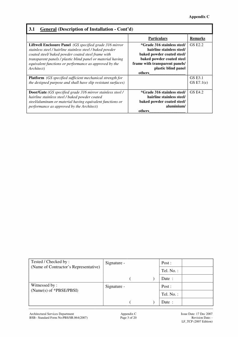
Appendix C
Signature - Post :
Tel. No. :
Tested / Checked by : (Name of Contractor’s Representative)
( ) Date :
Signature - Post :
Tel. No. :
Witnessed by : (Name(s) of *PBSE/PBSI)
( ) Date : Architectural Services Department Appendix C Issue Date: 17 Dec 2007 BSB– Standard Form No:PBS/SR.064(2007) Page 3 of 20 Revision Date: - LF_TCP (2007 Edition)
3.1 General (Description of Installation - Cont’d)
Particulars Remarks
Liftwell Enclosure Panel (GS specified grade 316 mirror stainless steel / hairline stainless steel / baked powder coated steel/ baked powder coated steel frame with transparent panels / plastic blind panel or material having equivalent functions or performance as approved by the Architect)
*Grade 316 stainless steel/ hairline stainless steel/
baked powder coated steel/ baked powder coated steel
frame with transparent panels/ plastic blind panel
others__________________
GS E2.2
Platform (GS specified sufficient mechanical strength for the designed purpose and shall have slip resistant surfaces)
GS E3.1 GS E7.1(e)
Door/Gate (GS specified grade 316 mirror stainless steel / hairline stainless steel / baked powder coated steel/aluminum or material having equivalent functions or performance as approved by the Architect)
*Grade 316 stainless steel/ hairline stainless steel/
baked powder coated steel/ aluminium/
others__________________
GS E4.2
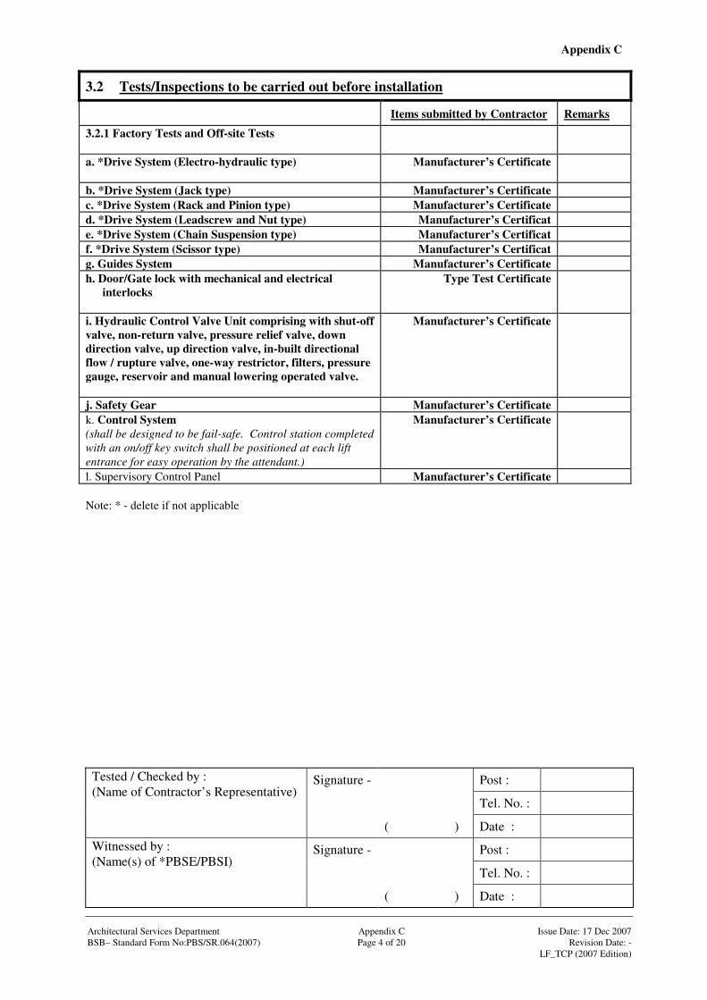
Appendix C
Signature - Post :
Tel. No. :
Tested / Checked by : (Name of Contractor’s Representative)
( ) Date :
Signature - Post :
Tel. No. :
Witnessed by : (Name(s) of *PBSE/PBSI)
( ) Date : Architectural Services Department Appendix C Issue Date: 17 Dec 2007 BSB– Standard Form No:PBS/SR.064(2007) Page 4 of 20 Revision Date: - LF_TCP (2007 Edition)
3.2 Tests/Inspections to be carried out before installation
Items submitted by Contractor Remarks
3.2.1 Factory Tests and Off-site Tests
a. *Drive System (Electro-hydraulic type)
Manufacturer’s Certificate
b. *Drive System (Jack type) Manufacturer’s Certificate c. *Drive System (Rack and Pinion type) Manufacturer’s Certificate d. *Drive System (Leadscrew and Nut type) Manufacturer’s Certificat e. *Drive System (Chain Suspension type) Manufacturer’s Certificat f. *Drive System (Scissor type) Manufacturer’s Certificat g. Guides System Manufacturer’s Certificate h. Door/Gate lock with mechanical and electrical
interlocks
Type Test Certificate
i. Hydraulic Control Valve Unit comprising with shut-off valve, non-return valve, pressure relief valve, down direction valve, up direction valve, in-built directional flow / rupture valve, one-way restrictor, filters, pressure gauge, reservoir and manual lowering operated valve.
Manufacturer’s Certificate
j. Safety Gear Manufacturer’s Certificate k. Control System (shall be designed to be fail-safe. Control station completed with an on/off key switch shall be positioned at each lift entrance for easy operation by the attendant.)
Manufacturer’s Certificate
l. Supervisory Control Panel Manufacturer’s Certificate Note: * - delete if not applicable
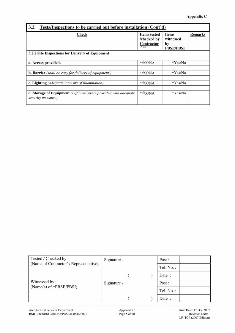
Appendix C
Signature - Post :
Tel. No. :
Tested / Checked by : (Name of Contractor’s Representative)
( ) Date :
Signature - Post :
Tel. No. :
Witnessed by : (Name(s) of *PBSE/PBSI)
( ) Date : Architectural Services Department Appendix C Issue Date: 17 Dec 2007 BSB– Standard Form No:PBS/SR.064(2007) Page 5 of 20 Revision Date: - LF_TCP (2007 Edition)
3.2. Tests/Inspections to be carried out before installation (Cont’d)
Check Items tested /checked by Contractor (Note 1)
Items witnessed by PBSE/PBSI
Remarks
3.2.2 Site Inspections for Delivery of Equipment a. Access provided. *√/X/NA *Yes/No b. Barrier (shall be easy for delivery of equipment.) *√/X/NA *Yes/No c. Lighting (adequate intensity of illumination) *√/X/NA *Yes/No d. Storage of Equipment (sufficient space provided with adequate security measure.)
*√/X/NA *Yes/No

Appendix C
Signature - Post :
Tel. No. :
Tested / Checked by : (Name of Contractor’s Representative)
( ) Date :
Signature - Post :
Tel. No. :
Witnessed by : (Name(s) of *PBSE/PBSI)
( ) Date : Architectural Services Department Appendix C Issue Date: 17 Dec 2007 BSB– Standard Form No:PBS/SR.064(2007) Page 6 of 20 Revision Date: - LF_TCP (2007 Edition)
3.2. Tests/Inspections to be carried out before installation (Cont’d)
Check Make Model No. Country of Origin
Approval document provided
Items tested /checked by Contractor (Note 1)
Items witnessed by PBSE/PBSI
Remarks
3.2.3 Inspection of Materials/Equipment delivered to site a. Drive System
*√/X/NA *√/X/NA *Yes/No
b. Guides System
*√/X/NA *√/X/NA *Yes/No
c. Door/Gate Lock
*√/X/NA *√/X/NA *Yes/No
d. Hydraulic Control Valve Unit
*√/X/NA *√/X/NA *Yes/No
e. Handrail
*√/X/NA *√/X/NA *Yes/No
f. Others
*√/X/NA *√/X/NA *Yes/No
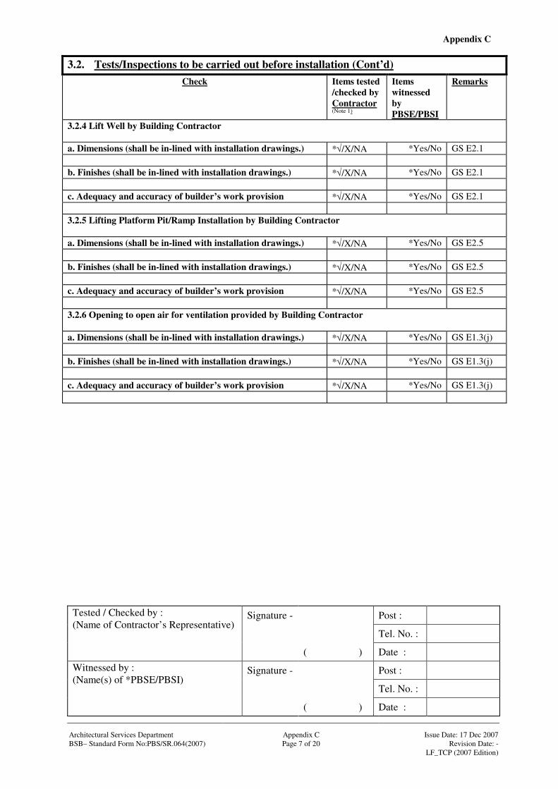
Appendix C
Signature - Post :
Tel. No. :
Tested / Checked by : (Name of Contractor’s Representative)
( ) Date :
Signature - Post :
Tel. No. :
Witnessed by : (Name(s) of *PBSE/PBSI)
( ) Date : Architectural Services Department Appendix C Issue Date: 17 Dec 2007 BSB– Standard Form No:PBS/SR.064(2007) Page 7 of 20 Revision Date: - LF_TCP (2007 Edition)
3.2. Tests/Inspections to be carried out before installation (Cont’d)
Check Items tested /checked by Contractor (Note 1)
Items witnessed by PBSE/PBSI
Remarks
3.2.4 Lift Well by Building Contractor a. Dimensions (shall be in-lined with installation drawings.) *√/X/NA *Yes/No GS E2.1 b. Finishes (shall be in-lined with installation drawings.) *√/X/NA *Yes/No GS E2.1 c. Adequacy and accuracy of builder’s work provision *√/X/NA *Yes/No GS E2.1 3.2.5 Lifting Platform Pit/Ramp Installation by Building Contractor a. Dimensions (shall be in-lined with installation drawings.) *√/X/NA *Yes/No GS E2.5 b. Finishes (shall be in-lined with installation drawings.) *√/X/NA *Yes/No GS E2.5 c. Adequacy and accuracy of builder’s work provision *√/X/NA *Yes/No GS E2.5 3.2.6 Opening to open air for ventilation provided by Building Contractor a. Dimensions (shall be in-lined with installation drawings.) *√/X/NA *Yes/No GS E1.3(j) b. Finishes (shall be in-lined with installation drawings.) *√/X/NA *Yes/No GS E1.3(j) c. Adequacy and accuracy of builder’s work provision *√/X/NA *Yes/No GS E1.3(j)

Appendix C
Signature - Post :
Tel. No. :
Tested / Checked by : (Name of Contractor’s Representative)
( ) Date :
Signature - Post :
Tel. No. :
Witnessed by : (Name(s) of *PBSE/PBSI)
( ) Date : Architectural Services Department Appendix C Issue Date: 17 Dec 2007 BSB– Standard Form No:PBS/SR.064(2007) Page 8 of 20 Revision Date: - LF_TCP (2007 Edition)
3.2. Tests/Inspections to be carried out before installation (Cont’d)
Check Items tested /checked by Contractor (Note 1)
Items witnessed by PBSE/PBSI
Remarks
3.2.7 Electrical Services provided by Electrical Contractor
a. Lockable fused isolator with proper labeling shall be provided adjacent to the lift machine compartment
*√/X/NA *Yes/No GS B2.2
b. RCD protection device shall be provided for the main supply of the lift machine compartment
*√/X/NA *Yes/No
c. Earth bonding for metallic parts shall be provided *√/X/NA *Yes/No GS B2.4 d. Separately fused permanent lighting supply independent of the powered vertical lifting platform installation shall be illuminated to at least 50 lux at above the landings and lift well
*√/X/NA *Yes/No GS E2.3
e. Emergency lighting of at least 1 W lamp fed by an automatically rechargeable battery supply which shall be capable of operating the emergency light for at least 2 hours in case of an interruption upon failure of the normal power supply
*√/X/NA *Yes/No GS E2.3 & E3.3
f. 13A socket of emergency power supply adjacent to the call bell panel
*√/X/NA *Yes/No GS E8.1
g. Cable containment facilities from the lift well at the landing of designated point of entry to the position of the supervisory control panel and call bell system
*√/X/NA *Yes/No GS B2.2 GS E8.1 GS E8.2
h. Where the maximum vertical travel of the Powered Vertical Lifting Platform Installation exceeds 1980 mm, an intercom system and CCTV system shall be provided and the cable containment facilities from the lift well at the landing of designated point of entry to the position of the call bell panel integrated with intercom system and CCTV.
*√/X/NA *Yes/No GS B2.2 GS E8.3 GS E8.4
3.2.8 Fire Services provided by Fire Service Contractor Fire signal dry contact at a point near to the Powered Vertical Lifting Platform Installation control panel
*√/X/NA *Yes/No GS E9.2
3.2.9 Other tests/inspections for setting to work, safety and quality tests etc. required before commencing installation works

Appendix C
Signature - Post :
Tel. No. :
Tested / Checked by : (Name of Contractor’s Representative)
( ) Date :
Signature - Post :
Tel. No. :
Witnessed by : (Name(s) of *PBSE/PBSI)
( ) Date : Architectural Services Department Appendix C Issue Date: 17 Dec 2007 BSB– Standard Form No:PBS/SR.064(2007) Page 9 of 20 Revision Date: - LF_TCP (2007 Edition)
3.3. Tests/Inspections to be carried out during installation Check Items tested
/checked by Contractor (Note 1)
Items witnessed by PBSE/PBSI
Remarks
3.3.1 Drive System a) *Electro-hydraulic Type
*√/X/NA
*Yes/No GS E5.2
b) *Jack Type
*√/X/NA
*Yes/No GS E5.2 (a)
c) *Rack and Pinion Type
*√/X/NA
*Yes/No GS E5.2 (b)
d) *Leadscrew and Nut Type
*√/X/NA
*Yes/No GS E5.2 ©
e) *Chain Suspension Type *√/X/NA
*Yes/No GS E5.2 (d)
f) *Scissor Type *√/X/NA
*Yes/No GS E5.2 (e)
3.3.2 Guides System *√/X/NA
*Yes/No GS E5.1
3.3.3 Landing Door/Gate: a) Height of landing Door/Gate (The platform with travel less than 1980 mm shall be
protected by a gate of at least 1100 mm in height at landing entrance, and if the travel is more than 1980 mm, the platform shall be protected by a door of at least 2000 mm in height at landing entrance.)
mm *Yes/No GS E4.2
Other tests/inspections for setting to work, safety and quality tests etc. required before energisation *√/X/NA *Yes/No *√/X/NA *Yes/No Note: * - delete if not applicable
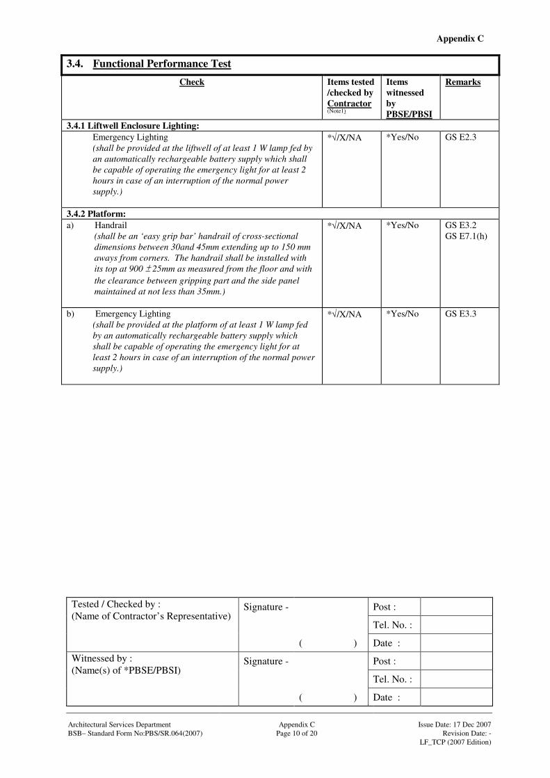
Appendix C
Signature - Post :
Tel. No. :
Tested / Checked by : (Name of Contractor’s Representative)
( ) Date :
Signature - Post :
Tel. No. :
Witnessed by : (Name(s) of *PBSE/PBSI)
( ) Date : Architectural Services Department Appendix C Issue Date: 17 Dec 2007 BSB– Standard Form No:PBS/SR.064(2007) Page 10 of 20 Revision Date: - LF_TCP (2007 Edition)
3.4. Functional Performance Test Check Items tested
/checked by Contractor (Note1)
Items witnessed by PBSE/PBSI
Remarks
3.4.1 Liftwell Enclosure Lighting: Emergency Lighting (shall be provided at the liftwell of at least 1 W lamp fed by an automatically rechargeable battery supply which shall be capable of operating the emergency light for at least 2 hours in case of an interruption of the normal power supply.)
*√/X/NA
*Yes/No GS E2.3
3.4.2 Platform: a) Handrail
(shall be an ‘easy grip bar’ handrail of cross-sectional dimensions between 30and 45mm extending up to 150 mm aways from corners. The handrail shall be installed with its top at 900 25mm as measured from the floor and with the clearance between gripping part and the side panel maintained at not less than 35mm.)
*√/X/NA
*Yes/No GS E3.2 GS E7.1(h)
b) Emergency Lighting (shall be provided at the platform of at least 1 W lamp fed by an automatically rechargeable battery supply which shall be capable of operating the emergency light for at least 2 hours in case of an interruption of the normal power supply.)
*√/X/NA
*Yes/No GS E3.3
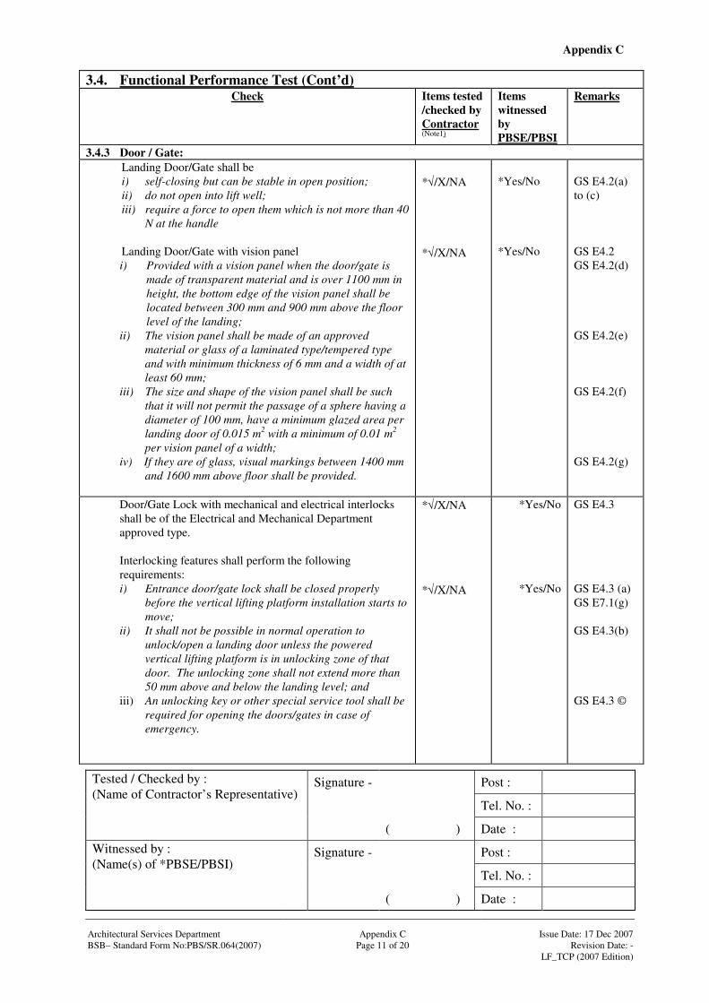
Appendix C
Signature - Post :
Tel. No. :
Tested / Checked by : (Name of Contractor’s Representative)
( ) Date :
Signature - Post :
Tel. No. :
Witnessed by : (Name(s) of *PBSE/PBSI)
( ) Date : Architectural Services Department Appendix C Issue Date: 17 Dec 2007 BSB– Standard Form No:PBS/SR.064(2007) Page 11 of 20 Revision Date: - LF_TCP (2007 Edition)
3.4. Functional Performance Test (Cont’d)
Check Items tested /checked by Contractor (Note1)
Items witnessed by PBSE/PBSI
Remarks
3.4.3 Door / Gate: Landing Door/Gate shall be i) self-closing but can be stable in open position; ii) do not open into lift well; iii) require a force to open them which is not more than 40
N at the handle Landing Door/Gate with vision panel i) Provided with a vision panel when the door/gate is
made of transparent material and is over 1100 mm in height, the bottom edge of the vision panel shall be located between 300 mm and 900 mm above the floor level of the landing;
ii) The vision panel shall be made of an approved material or glass of a laminated type/tempered type and with minimum thickness of 6 mm and a width of at least 60 mm;
iii) The size and shape of the vision panel shall be such that it will not permit the passage of a sphere having a diameter of 100 mm, have a minimum glazed area per landing door of 0.015 m2 with a minimum of 0.01 m2 per vision panel of a width;
iv) If they are of glass, visual markings between 1400 mm and 1600 mm above floor shall be provided.
*√/X/NA *√/X/NA
*Yes/No *Yes/No
GS E4.2(a) to (c) GS E4.2 GS E4.2(d) GS E4.2(e) GS E4.2(f) GS E4.2(g)
Door/Gate Lock with mechanical and electrical interlocks shall be of the Electrical and Mechanical Department approved type. Interlocking features shall perform the following requirements: i) Entrance door/gate lock shall be closed properly
before the vertical lifting platform installation starts to move;
ii) It shall not be possible in normal operation to unlock/open a landing door unless the powered vertical lifting platform is in unlocking zone of that door. The unlocking zone shall not extend more than 50 mm above and below the landing level; and
iii) An unlocking key or other special service tool shall be required for opening the doors/gates in case of emergency.
*√/X/NA *√/X/NA
*Yes/No
*Yes/No
GS E4.3 GS E4.3 (a) GS E7.1(g) GS E4.3(b) GS E4.3 ©
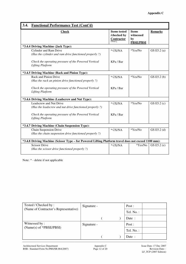
Appendix C
Signature - Post :
Tel. No. :
Tested / Checked by : (Name of Contractor’s Representative)
( ) Date :
Signature - Post :
Tel. No. :
Witnessed by : (Name(s) of *PBSE/PBSI)
( ) Date : Architectural Services Department Appendix C Issue Date: 17 Dec 2007 BSB– Standard Form No:PBS/SR.064(2007) Page 12 of 20 Revision Date: - LF_TCP (2007 Edition)
3.4. Functional Performance Test (Cont’d)
Check Items tested /checked by Contractor (Note1)
Items witnessed by PBSE/PBSI
Remarks
*3.4.4 Driving Machine (Jack Type): Cylinder and Ram Drive (Has the cylinder and ram drive functioned properly ?) Check the operating pressure of the Powered Vertical Lifting Platform
*√/X/NA KPa / Bar
*Yes/No GS E5.2 (a)
*3.4.5 Driving Machine (Rack and Pinion Type): Rack and Pinion Drive (Has the rack an pinion drive functioned properly ?) Check the operating pressure of the Powered Vertical Lifting Platform
*√/X/NA KPa / Bar
*Yes/No GS E5.2 (b)
*3.4.6 Driving Machine (Leadscrew and Nut Type): Leadscrew and Nut Drive (Has the leadscrew and nut drive functioned properly ?) Check the operating pressure of the Powered Vertical Lifting Platform
*√/X/NA KPa / Bar
*Yes/No GS E5.2 (c)
*3.4.7 Driving Machine (Chain Suspension Type): Chain Suspension Drive (Has the chain suspension drive functioned properly ?)
*√/X/NA
*Yes/No GS E5.2 (d)
*3.4.8 Driving Machine (Scissor Type – for Powered Lifting Platform travel does not exceed 1100 mm): Scissor Drive (Has the scissor drive functioned properly ?)
*√/X/NA
*Yes/No GS E5.2 (e)
Note: * - delete if not applicable
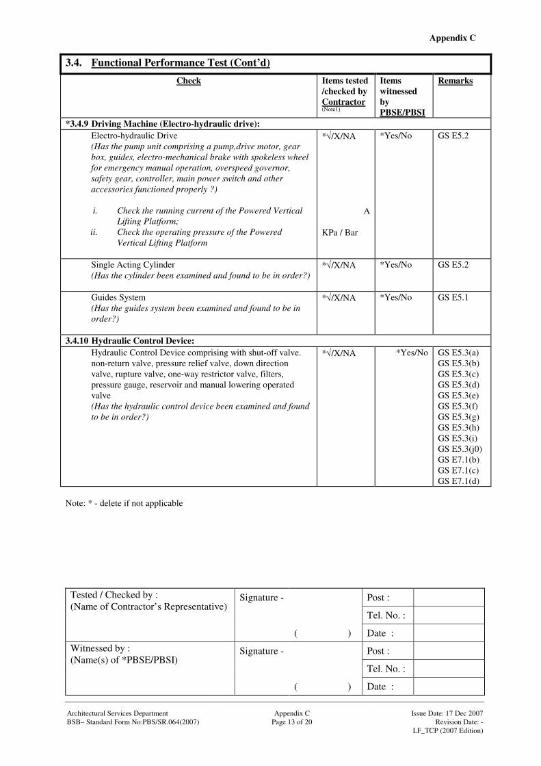
Appendix C
Signature - Post :
Tel. No. :
Tested / Checked by : (Name of Contractor’s Representative)
( ) Date :
Signature - Post :
Tel. No. :
Witnessed by : (Name(s) of *PBSE/PBSI)
( ) Date : Architectural Services Department Appendix C Issue Date: 17 Dec 2007 BSB– Standard Form No:PBS/SR.064(2007) Page 13 of 20 Revision Date: - LF_TCP (2007 Edition)
3.4. Functional Performance Test (Cont’d)
Check Items tested /checked by Contractor (Note1)
Items witnessed by PBSE/PBSI
Remarks
*3.4.9 Driving Machine (Electro-hydraulic drive): Electro-hydraulic Drive (Has the pump unit comprising a pump,drive motor, gear box, guides, electro-mechanical brake with spokeless wheel for emergency manual operation, overspeed governor, safety gear, controller, main power switch and other accessories functioned properly ?) i. Check the running current of the Powered Vertical
Lifting Platform; ii. Check the operating pressure of the Powered
Vertical Lifting Platform
*√/X/NA
A
KPa / Bar
*Yes/No GS E5.2
Single Acting Cylinder (Has the cylinder been examined and found to be in order?)
*√/X/NA
*Yes/No GS E5.2
Guides System (Has the guides system been examined and found to be in order?)
*√/X/NA
*Yes/No GS E5.1
3.4.10 Hydraulic Control Device: Hydraulic Control Device comprising with shut-off valve. non-return valve, pressure relief valve, down direction valve, rupture valve, one-way restrictor valve, filters, pressure gauge, reservoir and manual lowering operated valve (Has the hydraulic control device been examined and found to be in order?)
*√/X/NA
*Yes/No GS E5.3(a) GS E5.3(b) GS E5.3(c) GS E5.3(d) GS E5.3(e) GS E5.3(f) GS E5.3(g) GS E5.3(h) GS E5.3(i) GS E5.3(j0) GS E7.1(b) GS E7.1(c) GS E7.1(d)
Note: * - delete if not applicable
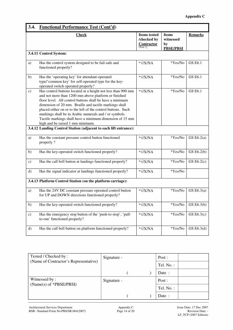
Appendix C
Signature - Post :
Tel. No. :
Tested / Checked by : (Name of Contractor’s Representative)
( ) Date :
Signature - Post :
Tel. No. :
Witnessed by : (Name(s) of *PBSE/PBSI)
( ) Date : Architectural Services Department Appendix C Issue Date: 17 Dec 2007 BSB– Standard Form No:PBS/SR.064(2007) Page 14 of 20 Revision Date: - LF_TCP (2007 Edition)
3.4. Functional Performance Test (Cont’d)
Check Items tested /checked by Contractor (Note 1)
Items witnessed by PBSE/PBSI
Remarks
3.4.11 Control System: a) Has the control system designed to be fail-safe and
functioned properly?
*√/X/NA
*Yes/No GS E6.1
b) Has the ‘operating key’ for attendant-operated type/’common key’ for self-operated type for the key-operated switch operated properly?
*√/X/NA
*Yes/No GS E6.1
c) Has control buttons located at a height not less than 900 mm and not more than 1200 mm above platform or finished floor level. All control buttons shall be have a minimum dimension of 20 mm. Braille and tactile markings shall placed either on or to the left of the control buttons. Such markings shall be in Arabic numerals and / or symbols. Tactile markings shall have a minimum dimension of 15 mm high and be raised 1 mm minimum.
*√/X/NA
*Yes/No GS E6.1
3.4.12 Landing Control Station (adjacent to each lift entrance): a) Has the constant pressure control button functioned
properly ?
*√/X/NA
*Yes/No GS E6.2(a)
b) Has the key-operated switch functioned properly?
*√/X/NA
*Yes/No GS E6.2(b)
c) Has the call bell button at landings functioned properly?
*√/X/NA
*Yes/No GS E6.2(c)
d) Has the signal indicator at landings functioned properly?
*√/X/NA
*Yes/No
3.4.13 Platform Control Station (on the platform carriage): a) Has the 24V DC constant pressure operated control button
for UP and DOWN directions functioned properly?
*√/X/NA
*Yes/No GS E6.3(a)
b) Has the key-operated switch functioned properly?
*√/X/NA
*Yes/No GS E6.3(b)
c) Has the emergency stop button of the ‘push-to-stop’, ‘pull-to-run’ functioned properly?
*√/X/NA
*Yes/No GS E6.3(c)
d) Has the call bell button on platform functioned properly?
*√/X/NA
*Yes/No GS E6.3(d)

Appendix C
Signature - Post :
Tel. No. :
Tested / Checked by : (Name of Contractor’s Representative)
( ) Date :
Signature - Post :
Tel. No. :
Witnessed by : (Name(s) of *PBSE/PBSI)
( ) Date : Architectural Services Department Appendix C Issue Date: 17 Dec 2007 BSB– Standard Form No:PBS/SR.064(2007) Page 15 of 20 Revision Date: - LF_TCP (2007 Edition)
3.4. Functional Performance Test (Cont’d)
Check Items tested /checked by Contractor (Note 1)
Items witnessed by PBSE/PBSI
Remarks
3.4.14 Safety Device: a) Has the mechanical blocking device with an electric switch
where fitted, been checked for correct operation?
*√/X/NA
*Yes/No GS E7.1(a)
b) Has the pressure relief valves where fitted, been checked for correct operation?
*√/X/NA
*Yes/No GS E5.3(c) GS E7.1(b)
c) Has the rupture valve where fitted, been checked for correct operation?
*√/X/NA
*Yes/No GS E5.3(e) GS E7.1(c)
d) Has the one-way restrictor valve where fitted, been checked for correct operation?
*√/X/NA
*Yes/No GS E5.3(f)
e) Has the manual (emergency) operating valve where fitted, been checked for correct operation?
*√/X/NA
*Yes/No GS E5.3(j) GS E7.1(d)
f) Has the positively operated safety switches where fitted, been checked for correct operation?
*√/X/NA
*Yes/No GS E7.1(f)
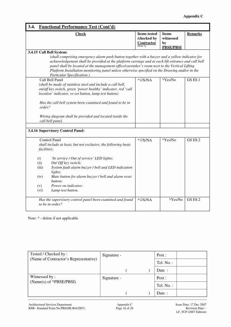
Appendix C
Signature - Post :
Tel. No. :
Tested / Checked by : (Name of Contractor’s Representative)
( ) Date :
Signature - Post :
Tel. No. :
Witnessed by : (Name(s) of *PBSE/PBSI)
( ) Date : Architectural Services Department Appendix C Issue Date: 17 Dec 2007 BSB– Standard Form No:PBS/SR.064(2007) Page 16 of 20 Revision Date: - LF_TCP (2007 Edition)
3.4. Functional Performance Test (Cont’d)
Check Items tested /checked by Contractor (Note 1)
Items witnessed by PBSE/PBSI
Remarks
3.4.15 Call Bell System: (shall comprising emergency alarm push button together with a buzzer and a yellow indicator for acknowledgement shall be provided at the platform carriage and at each lift entrance and call bell panel shall be located at the management office/caretaker’s room next to the Vertical Lifting Platform Installation monitoring panel unless otherwise specified on the Drawing and/or in the Particular Specification.)
Call Bell Panel (shall be made of stainless steel and include a call bell, on/off key switch, green ‘power healthy’ indicator, red ‘call location’ indicator, re-set button, lamp test button)
Has the call bell system been examined and found to be in order?
Wiring diagram shall be provided and located inside the call bell panel.
*√/X/NA
*Yes/No GS E8.1
3.4.16 Supervisory Control Panel:
Control Panel shall include at least, but not exclusive, the following basic facilities:
(i) ‘In service / Out of service’ LED lights; (ii) On/ Off key switch; (iii) System fault alarm buzzer / bell and LED indication
lights; (iv) Mute button for alarm buzzer / bell and alarm reset
button; (v) Power on indicator; (vi) Lamp test button.
*√/X/NA
*Yes/No GS E8.2
Has the supervisory control panel been examined and found to be in order?
*√/X/NA
*Yes/No GS E8.2
Note: * - delete if not applicable
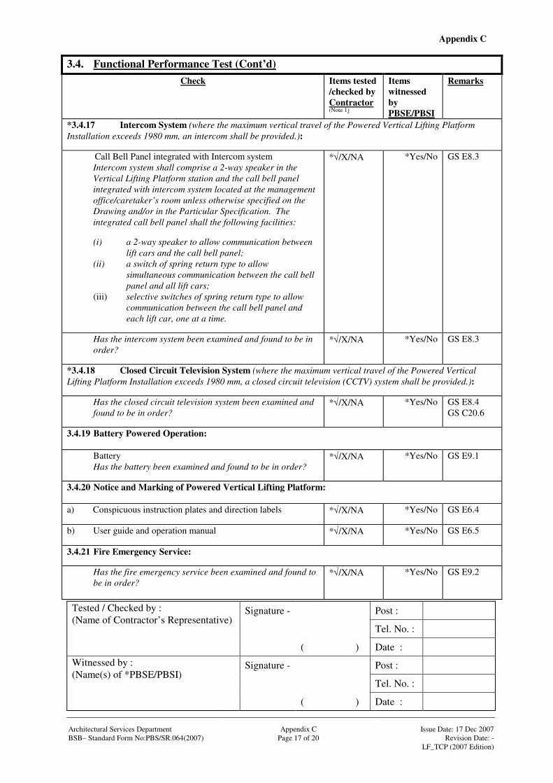
Appendix C
Signature - Post :
Tel. No. :
Tested / Checked by : (Name of Contractor’s Representative)
( ) Date :
Signature - Post :
Tel. No. :
Witnessed by : (Name(s) of *PBSE/PBSI)
( ) Date : Architectural Services Department Appendix C Issue Date: 17 Dec 2007 BSB– Standard Form No:PBS/SR.064(2007) Page 17 of 20 Revision Date: - LF_TCP (2007 Edition)
3.4. Functional Performance Test (Cont’d)
Check Items tested /checked by Contractor (Note 1)
Items witnessed by PBSE/PBSI
Remarks
*3.4.17 Intercom System (where the maximum vertical travel of the Powered Vertical Lifting Platform Installation exceeds 1980 mm, an intercom shall be provided.):
Call Bell Panel integrated with Intercom system Intercom system shall comprise a 2-way speaker in the Vertical Lifting Platform station and the call bell panel integrated with intercom system located at the management office/caretaker’s room unless otherwise specified on the Drawing and/or in the Particular Specification. The integrated call bell panel shall the following facilities: (i) a 2-way speaker to allow communication between
lift cars and the call bell panel; (ii) a switch of spring return type to allow
simultaneous communication between the call bell panel and all lift cars;
(iii) selective switches of spring return type to allow communication between the call bell panel and each lift car, one at a time.
*√/X/NA
*Yes/No GS E8.3
Has the intercom system been examined and found to be in order?
*√/X/NA
*Yes/No GS E8.3
*3.4.18 Closed Circuit Television System (where the maximum vertical travel of the Powered Vertical Lifting Platform Installation exceeds 1980 mm, a closed circuit television (CCTV) system shall be provided.):
Has the closed circuit television system been examined and found to be in order?
*√/X/NA
*Yes/No GS E8.4 GS C20.6
3.4.19 Battery Powered Operation:
Battery Has the battery been examined and found to be in order?
*√/X/NA
*Yes/No GS E9.1
3.4.20 Notice and Marking of Powered Vertical Lifting Platform: a) Conspicuous instruction plates and direction labels
*√/X/NA
*Yes/No GS E6.4
b) User guide and operation manual
*√/X/NA
*Yes/No GS E6.5
3.4.21 Fire Emergency Service:
Has the fire emergency service been examined and found to be in order?
*√/X/NA
*Yes/No GS E9.2
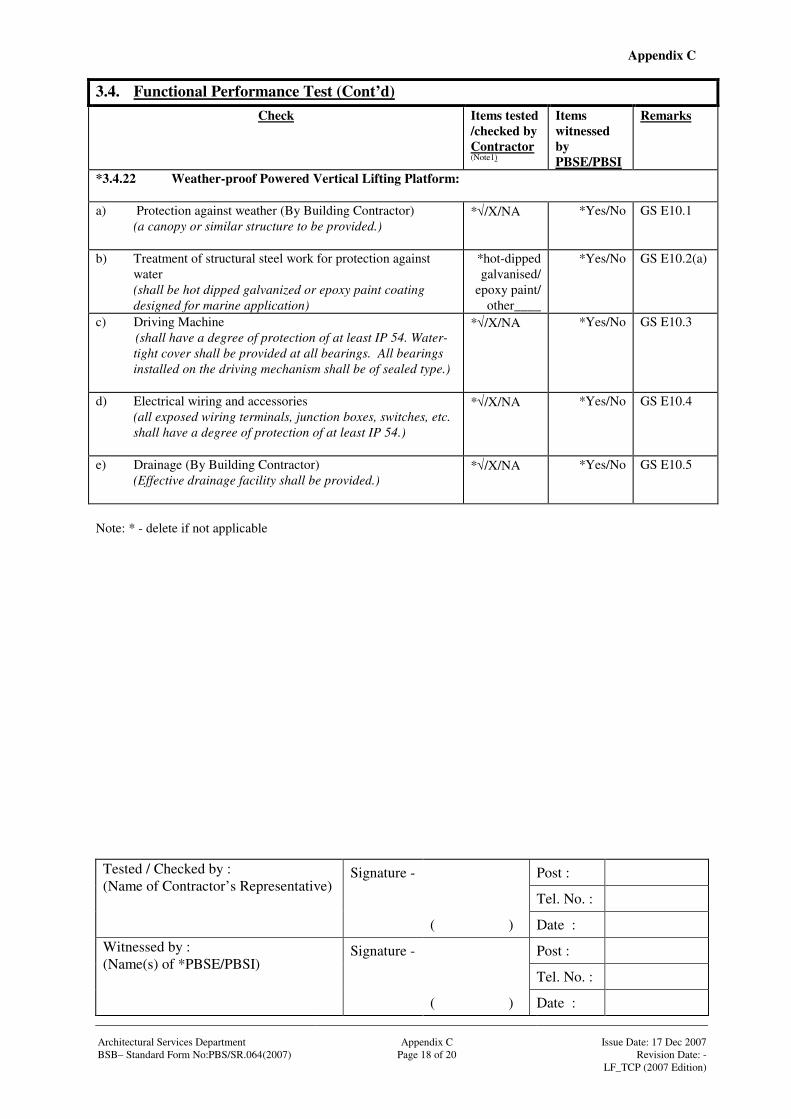
Appendix C
Signature - Post :
Tel. No. :
Tested / Checked by : (Name of Contractor’s Representative)
( ) Date :
Signature - Post :
Tel. No. :
Witnessed by : (Name(s) of *PBSE/PBSI)
( ) Date : Architectural Services Department Appendix C Issue Date: 17 Dec 2007 BSB– Standard Form No:PBS/SR.064(2007) Page 18 of 20 Revision Date: - LF_TCP (2007 Edition)
3.4. Functional Performance Test (Cont’d)
Check Items tested /checked by Contractor (Note1)
Items witnessed by PBSE/PBSI
Remarks
*3.4.22 Weather-proof Powered Vertical Lifting Platform: a) Protection against weather (By Building Contractor)
(a canopy or similar structure to be provided.)
*√/X/NA
*Yes/No GS E10.1
b) Treatment of structural steel work for protection against water
(shall be hot dipped galvanized or epoxy paint coating designed for marine application)
*hot-dipped galvanised/
epoxy paint/ other____
*Yes/No GS E10.2(a)
c) Driving Machine (shall have a degree of protection of at least IP 54. Water-tight cover shall be provided at all bearings. All bearings installed on the driving mechanism shall be of sealed type.)
*√/X/NA
*Yes/No GS E10.3
d) Electrical wiring and accessories (all exposed wiring terminals, junction boxes, switches, etc. shall have a degree of protection of at least IP 54.)
*√/X/NA
*Yes/No GS E10.4
e) Drainage (By Building Contractor) (Effective drainage facility shall be provided.)
*√/X/NA
*Yes/No GS E10.5
Note: * - delete if not applicable

Appendix C
Signature - Post :
Tel. No. :
Tested / Checked by : (Name of Contractor’s Representative)
( ) Date :
Signature - Post :
Tel. No. :
Witnessed by : (Name(s) of *PBSE/PBSI)
( ) Date : Architectural Services Department Appendix C Issue Date: 17 Dec 2007 BSB– Standard Form No:PBS/SR.064(2007) Page 19 of 20 Revision Date: - LF_TCP (2007 Edition)
3.5. Commissioning and Statutory Inspections Check Items tested
/checked by Contractor (Note1)
Items witnessed by PBSE/PBSI
Remarks
3.5.1 Half Hour Run:
The vertical lifting platform is to run unladen in the up direction followed by the down direction at least half hour period:
__________Observation
__________Observation
3.5.2 Other tests, inspections and examination as required in the relevant annexes

Appendix C
Architectural Services Department Appendix C Issue Date: 17 Dec 2007 BSB– Standard Form No:PBS/SR.064(2007) Page 20 of 20 Revision Date: - LF_TCP (2007 Edition)
3.6. Comments (if any)
Note 1: In the result column, √√√√ means (operating satisfactorily and complied with specified requirement). X (operating unsatisfactorily or did not comply with requirement. Please give detail), NA (not applicable) Symbols : * Delete as appropriate # Barrier Free Access Requirement Abbreviation : GS General Specification for Lift, Escalator and Passenger Conveyor Installation in Government Buildings of
the Hong Kong Special Administrative Region issued by the Architectural Services Department (2007 Ed) COP(D) Code of Practice on the Design and Construction of Lifts and Escalators issued by the Electrical and
Mechanical Services Department (2000 Ed) COP(LEW) Code of Practice for Lift Works and Escalator Works issued by the Electrical and Mechanical Services
Department (2002 Ed) BFA Design Manual: Barrier Free Access 1997 issued by Building Authority
Signature - Post :
Tel. No. :
Tested / Checked by : (Name of Contractor’s Representative)
( ) Date :
Signature - Post :
Tel. No. :
Witnessed by : (Name(s) of *PBSE/PBSI)
( ) Date :
Signature - Post :
Tel. No. :
Name in full : (Contractor’s Testing Engineer)
( ) Date :
Company Chop :
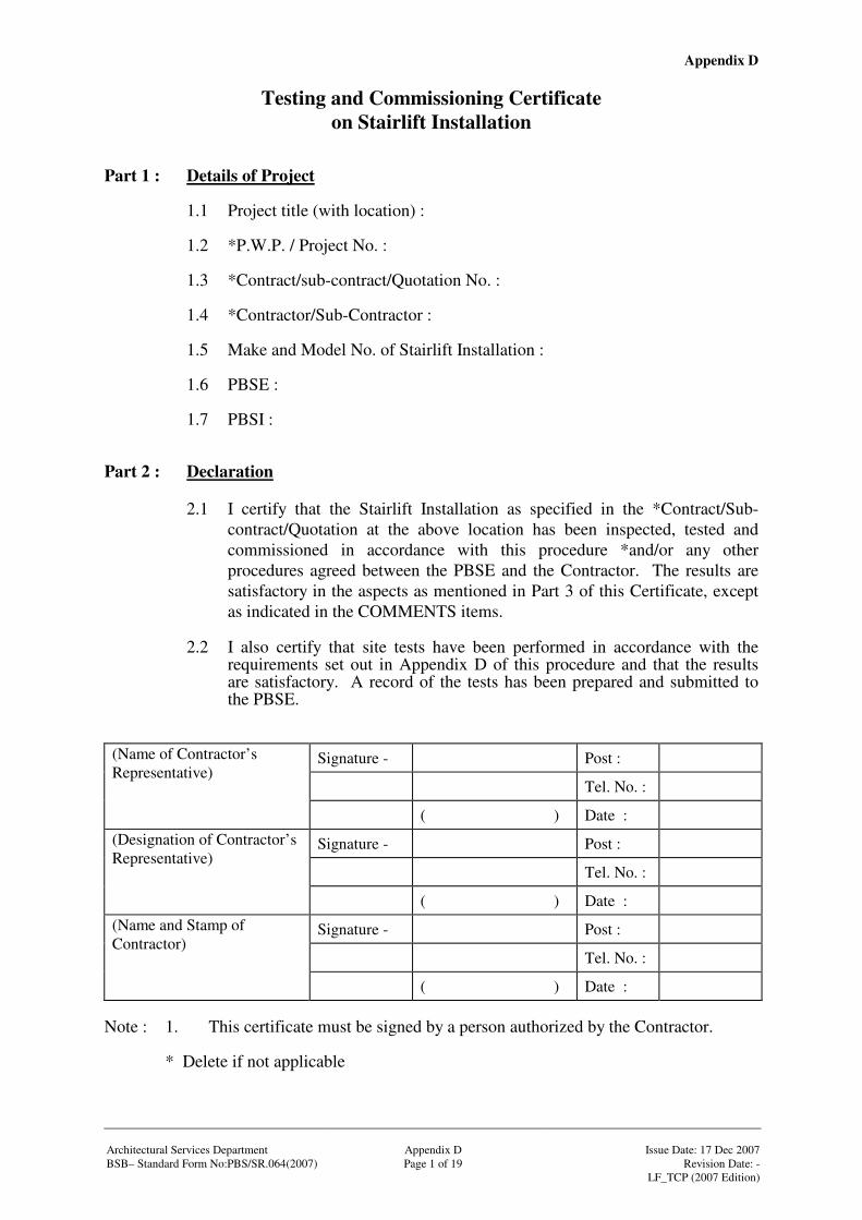
Appendix D
Architectural Services Department
Appendix D
Issue Date: 17 Dec 2007
BSB– Standard Form No:PBS/SR.064(2007) Page 1 of 19 Revision Date: - LF_TCP (2007 Edition)
Testing and Commissioning Certificate on Stairlift Installation
Part 1 : Details of Project
1.1 Project title (with location) : 1.2 *P.W.P. / Project No. : 1.3 *Contract/sub-contract/Quotation No. : 1.4 *Contractor/Sub-Contractor : 1.5 Make and Model No. of Stairlift Installation : 1.6 PBSE : 1.7 PBSI :
Part 2 : Declaration
2.1 I certify that the Stairlift Installation as specified in the *Contract/Sub-contract/Quotation at the above location has been inspected, tested and commissioned in accordance with this procedure *and/or any other procedures agreed between the PBSE and the Contractor. The results are satisfactory in the aspects as mentioned in Part 3 of this Certificate, except as indicated in the COMMENTS items.
2.2 I also certify that site tests have been performed in accordance with the
requirements set out in Appendix D of this procedure and that the results are satisfactory. A record of the tests has been prepared and submitted to the PBSE.
Signature - Post :
Tel. No. :
(Name of Contractor’s Representative)
( ) Date :
Signature - Post :
Tel. No. :
(Designation of Contractor’s Representative)
( ) Date :
Signature - Post :
Tel. No. :
(Name and Stamp of Contractor)
( ) Date : Note : 1. This certificate must be signed by a person authorized by the Contractor. * Delete if not applicable
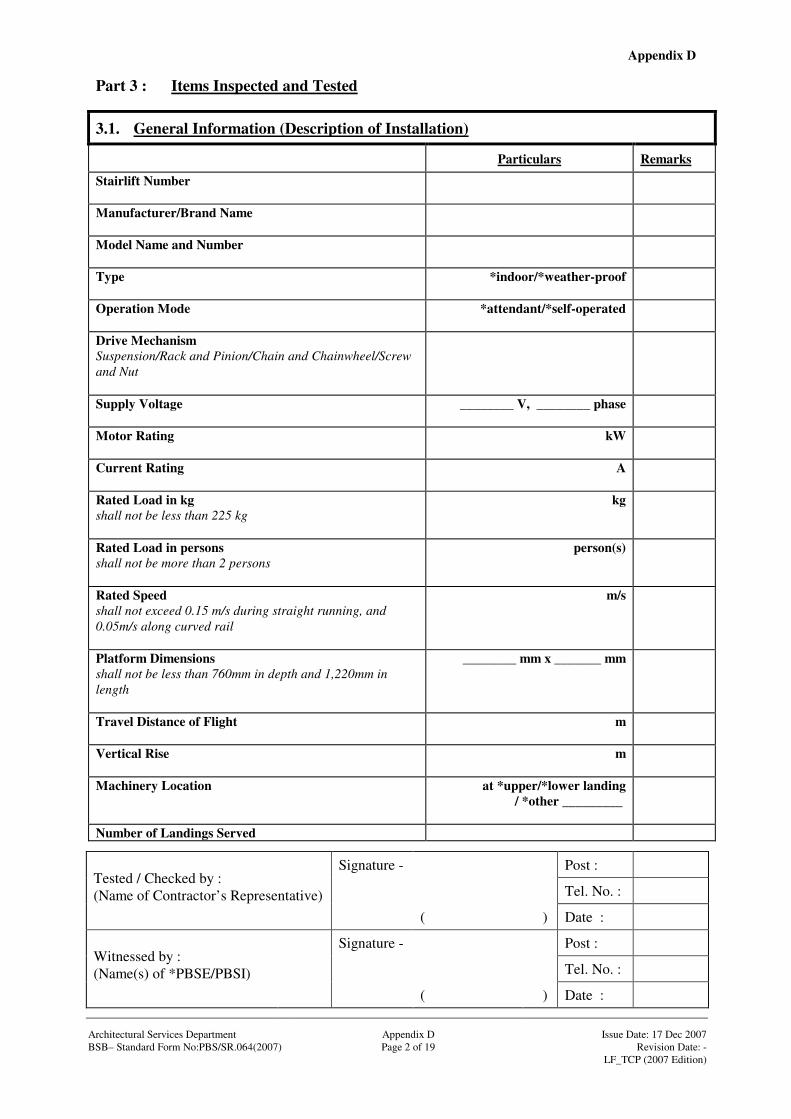
Appendix D
Signature - Post :
Tel. No. :
Tested / Checked by : (Name of Contractor’s Representative)
( ) Date :
Signature - Post :
Tel. No. :
Witnessed by : (Name(s) of *PBSE/PBSI)
( ) Date : Architectural Services Department Appendix D Issue Date: 17 Dec 2007 BSB– Standard Form No:PBS/SR.064(2007) Page 2 of 19 Revision Date: - LF_TCP (2007 Edition)
Part 3 : Items Inspected and Tested
3.1. General Information (Description of Installation)
Particulars Remarks
Stairlift Number
Manufacturer/Brand Name
Model Name and Number
Type
*indoor/*weather-proof
Operation Mode
*attendant/*self-operated
Drive Mechanism Suspension/Rack and Pinion/Chain and Chainwheel/Screw and Nut
Supply Voltage ________ V, ________ phase
Motor Rating
kW
Current Rating
A
Rated Load in kg shall not be less than 225 kg
kg
Rated Load in persons shall not be more than 2 persons
person(s)
Rated Speed shall not exceed 0.15 m/s during straight running, and 0.05m/s along curved rail
m/s
Platform Dimensions shall not be less than 760mm in depth and 1,220mm in length
________ mm x _______ mm
Travel Distance of Flight
m
Vertical Rise
m
Machinery Location
at *upper/*lower landing / *other _________
Number of Landings Served
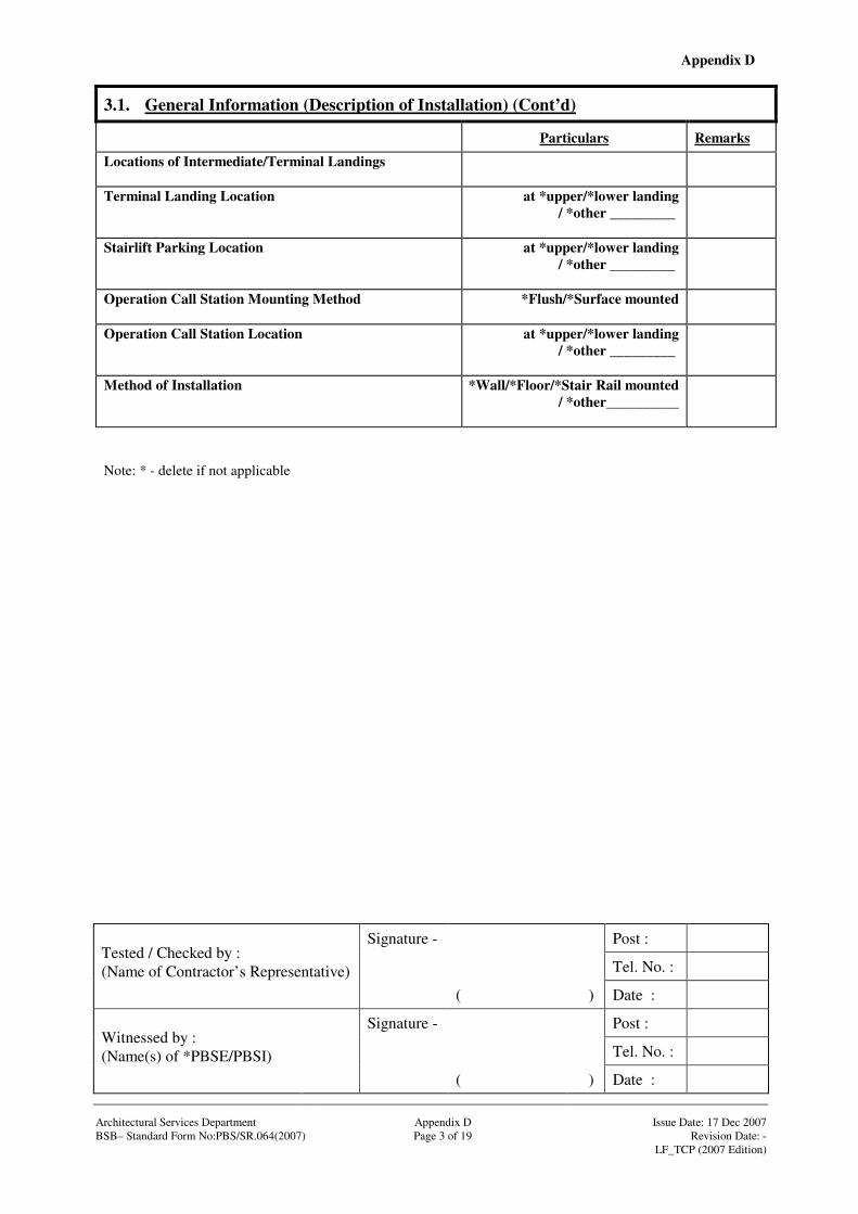
Appendix D
Signature - Post :
Tel. No. :
Tested / Checked by : (Name of Contractor’s Representative)
( ) Date :
Signature - Post :
Tel. No. :
Witnessed by : (Name(s) of *PBSE/PBSI)
( ) Date : Architectural Services Department Appendix D Issue Date: 17 Dec 2007 BSB– Standard Form No:PBS/SR.064(2007) Page 3 of 19 Revision Date: - LF_TCP (2007 Edition)
3.1. General Information (Description of Installation) (Cont’d)
Particulars Remarks
Locations of Intermediate/Terminal Landings
Terminal Landing Location
at *upper/*lower landing / *other _________
Stairlift Parking Location
at *upper/*lower landing / *other _________
Operation Call Station Mounting Method
*Flush/*Surface mounted
Operation Call Station Location
at *upper/*lower landing / *other _________
Method of Installation
*Wall/*Floor/*Stair Rail mounted / *other__________
Note: * - delete if not applicable
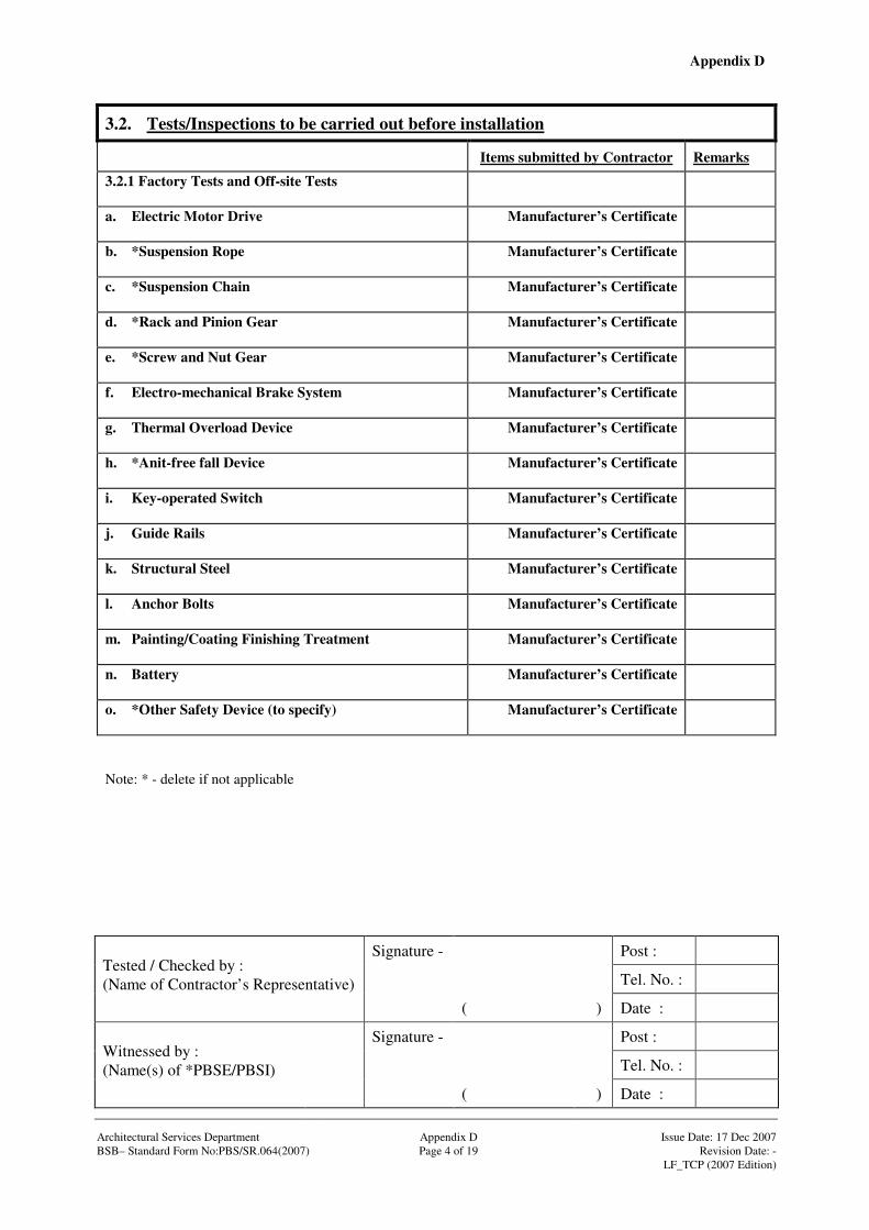
Appendix D
Signature - Post :
Tel. No. :
Tested / Checked by : (Name of Contractor’s Representative)
( ) Date :
Signature - Post :
Tel. No. :
Witnessed by : (Name(s) of *PBSE/PBSI)
( ) Date : Architectural Services Department Appendix D Issue Date: 17 Dec 2007 BSB– Standard Form No:PBS/SR.064(2007) Page 4 of 19 Revision Date: - LF_TCP (2007 Edition)
3.2. Tests/Inspections to be carried out before installation
Items submitted by Contractor Remarks
3.2.1 Factory Tests and Off-site Tests
a. Electric Motor Drive
Manufacturer’s Certificate
b. *Suspension Rope
Manufacturer’s Certificate
c. *Suspension Chain
Manufacturer’s Certificate
d. *Rack and Pinion Gear
Manufacturer’s Certificate
e. *Screw and Nut Gear
Manufacturer’s Certificate
f. Electro-mechanical Brake System
Manufacturer’s Certificate
g. Thermal Overload Device
Manufacturer’s Certificate
h. *Anit-free fall Device
Manufacturer’s Certificate
i. Key-operated Switch
Manufacturer’s Certificate
j. Guide Rails
Manufacturer’s Certificate
k. Structural Steel
Manufacturer’s Certificate
l. Anchor Bolts
Manufacturer’s Certificate
m. Painting/Coating Finishing Treatment
Manufacturer’s Certificate
n. Battery
Manufacturer’s Certificate
o. *Other Safety Device (to specify)
Manufacturer’s Certificate
Note: * - delete if not applicable
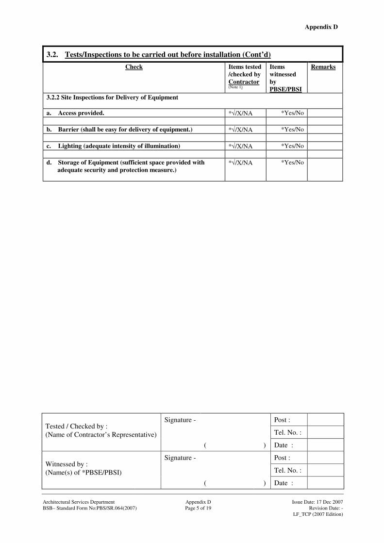
Appendix D
Signature - Post :
Tel. No. :
Tested / Checked by : (Name of Contractor’s Representative)
( ) Date :
Signature - Post :
Tel. No. :
Witnessed by : (Name(s) of *PBSE/PBSI)
( ) Date : Architectural Services Department Appendix D Issue Date: 17 Dec 2007 BSB– Standard Form No:PBS/SR.064(2007) Page 5 of 19 Revision Date: - LF_TCP (2007 Edition)
3.2. Tests/Inspections to be carried out before installation (Cont’d)
Check Items tested /checked by Contractor (Note 1)
Items witnessed by PBSE/PBSI
Remarks
3.2.2 Site Inspections for Delivery of Equipment a. Access provided. *√/X/NA *Yes/No b. Barrier (shall be easy for delivery of equipment.) *√/X/NA *Yes/No c. Lighting (adequate intensity of illumination) *√/X/NA *Yes/No d. Storage of Equipment (sufficient space provided with
adequate security and protection measure.)
*√/X/NA *Yes/No

Appendix D
Signature - Post :
Tel. No. :
Tested / Checked by : (Name of Contractor’s Representative)
( ) Date :
Signature - Post :
Tel. No. :
Witnessed by : (Name(s) of *PBSE/PBSI)
( ) Date : Architectural Services Department Appendix D Issue Date: 17 Dec 2007 BSB– Standard Form No:PBS/SR.064(2007) Page 6 of 19 Revision Date: - LF_TCP (2007 Edition)
3.2. Tests/Inspections to be carried out before installation (Cont’d)
Check Make Model No. Country of Origin
Approval document provided
Items tested /checked by Contractor (Note 1)
Items witnessed by PBSE/PBSI
Remarks
3.2.3 Inspection of Materials/Equipment delivered to site (Refer to Standard Form SR.054) a. Stairlift
*√/X/NA *Yes/No
b. Guide Rails
*√/X/NA *Yes/No
c. Structural Steel
*√/X/NA *Yes/No
d. Anchor Bolts
*√/X/NA *Yes/No
e. Control Panel
*√/X/NA *Yes/No
f. *External Driving System Panel
*√/X/NA *Yes/No
g. *Detachable Hand-held Attendant Control Pendant
*√/X/NA *Yes/No
Note: * - delete if not applicable
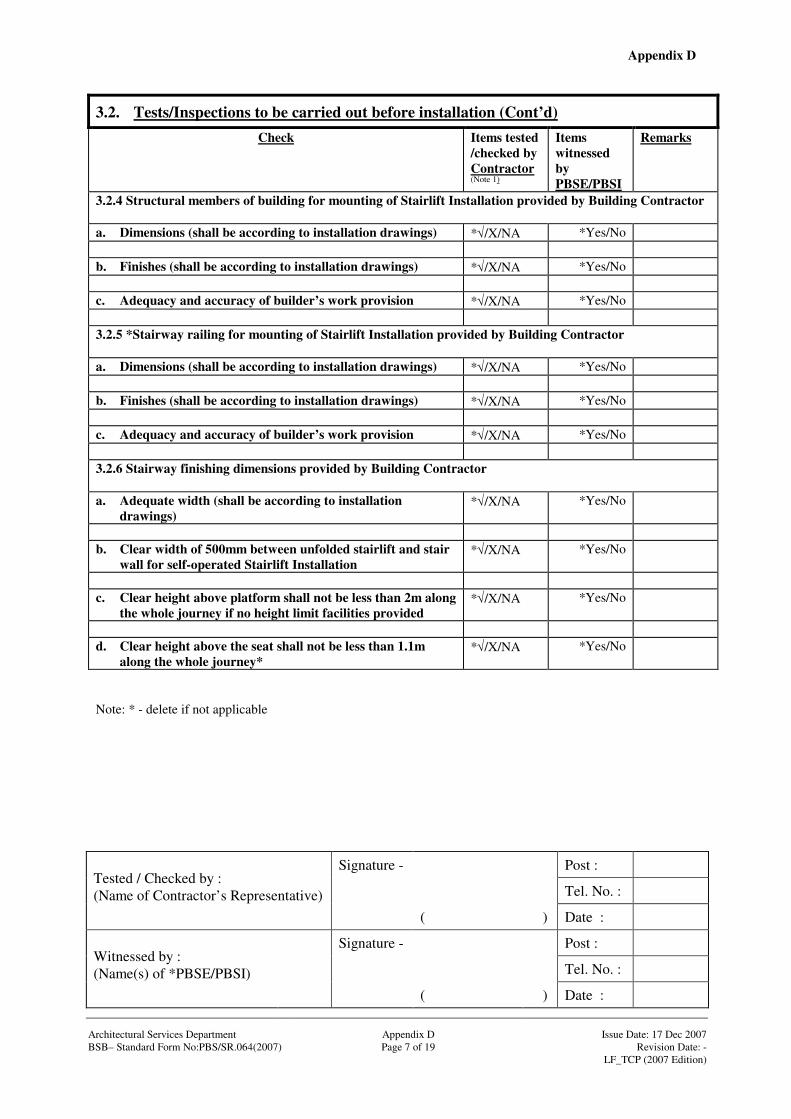
Appendix D
Signature - Post :
Tel. No. :
Tested / Checked by : (Name of Contractor’s Representative)
( ) Date :
Signature - Post :
Tel. No. :
Witnessed by : (Name(s) of *PBSE/PBSI)
( ) Date : Architectural Services Department Appendix D Issue Date: 17 Dec 2007 BSB– Standard Form No:PBS/SR.064(2007) Page 7 of 19 Revision Date: - LF_TCP (2007 Edition)
3.2. Tests/Inspections to be carried out before installation (Cont’d)
Check Items tested /checked by Contractor (Note 1)
Items witnessed by PBSE/PBSI
Remarks
3.2.4 Structural members of building for mounting of Stairlift Installation provided by Building Contractor a. Dimensions (shall be according to installation drawings) *√/X/NA *Yes/No b. Finishes (shall be according to installation drawings) *√/X/NA *Yes/No c. Adequacy and accuracy of builder’s work provision *√/X/NA *Yes/No 3.2.5 *Stairway railing for mounting of Stairlift Installation provided by Building Contractor a. Dimensions (shall be according to installation drawings) *√/X/NA *Yes/No b. Finishes (shall be according to installation drawings) *√/X/NA *Yes/No c. Adequacy and accuracy of builder’s work provision *√/X/NA *Yes/No 3.2.6 Stairway finishing dimensions provided by Building Contractor a. Adequate width (shall be according to installation
drawings) *√/X/NA *Yes/No
b. Clear width of 500mm between unfolded stairlift and stair
wall for self-operated Stairlift Installation *√/X/NA *Yes/No
c. Clear height above platform shall not be less than 2m along
the whole journey if no height limit facilities provided *√/X/NA *Yes/No
d. Clear height above the seat shall not be less than 1.1m
along the whole journey* *√/X/NA *Yes/No
Note: * - delete if not applicable

Appendix D
Signature - Post :
Tel. No. :
Tested / Checked by : (Name of Contractor’s Representative)
( ) Date :
Signature - Post :
Tel. No. :
Witnessed by : (Name(s) of *PBSE/PBSI)
( ) Date : Architectural Services Department Appendix D Issue Date: 17 Dec 2007 BSB– Standard Form No:PBS/SR.064(2007) Page 8 of 19 Revision Date: - LF_TCP (2007 Edition)
3.2. Tests/Inspections to be carried out before installation (Cont’d)
Check Items tested /checked by Contractor (Note 1)
Items witnessed by PBSE/PBSI
Remarks
3.2.7 Electrical Services provided by Electrical Contractor a. Lockable fused isolator with proper labeling shall be
provided adjacent to the Stairlift Installation *√/X/NA *Yes/No GS B2.2
b. RCD protection device shall be provided for the main
supply of the Stairlift Installation *√/X/NA *Yes/No
c. Earth bonding for all metallic parts shall be provided *√/X/NA *Yes/No GS B2.4 3.2.8 Fire Services provided by Fire Service Contractor Fire service signal dry contact at a point near to the control panel of Stairlift Installation
*√/X/NA *Yes/No GS F3.1
3.2.9 Other tests/inspections for setting to work, safety and quality tests etc. required before commencing installation works Please specify
*√/X/NA *Yes/No
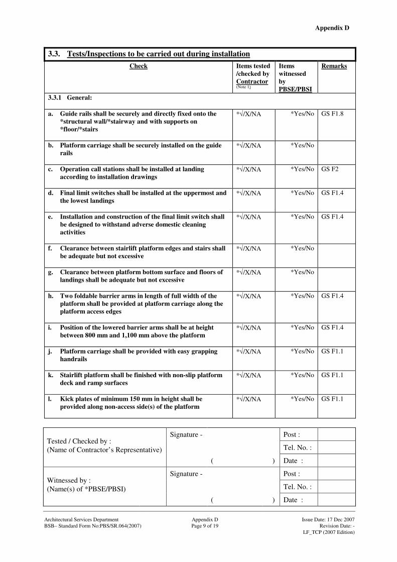
Appendix D
Signature - Post :
Tel. No. :
Tested / Checked by : (Name of Contractor’s Representative)
( ) Date :
Signature - Post :
Tel. No. :
Witnessed by : (Name(s) of *PBSE/PBSI)
( ) Date : Architectural Services Department Appendix D Issue Date: 17 Dec 2007 BSB– Standard Form No:PBS/SR.064(2007) Page 9 of 19 Revision Date: - LF_TCP (2007 Edition)
3.3. Tests/Inspections to be carried out during installation Check Items tested
/checked by Contractor (Note 1)
Items witnessed by PBSE/PBSI
Remarks
3.3.1 General: a. Guide rails shall be securely and directly fixed onto the
*structural wall/*stairway and with supports on *floor/*stairs
*√/X/NA
*Yes/No GS F1.8
b. Platform carriage shall be securely installed on the guide rails
*√/X/NA
*Yes/No
c. Operation call stations shall be installed at landing according to installation drawings
*√/X/NA
*Yes/No GS F2
d. Final limit switches shall be installed at the uppermost and the lowest landings
*√/X/NA
*Yes/No GS F1.4
e. Installation and construction of the final limit switch shall be designed to withstand adverse domestic cleaning activities
*√/X/NA
*Yes/No GS F1.4
f. Clearance between stairlift platform edges and stairs shall be adequate but not excessive
*√/X/NA
*Yes/No
g. Clearance between platform bottom surface and floors of landings shall be adequate but not excessive
*√/X/NA
*Yes/No
h. Two foldable barrier arms in length of full width of the platform shall be provided at platform carriage along the platform access edges
*√/X/NA
*Yes/No GS F1.4
i. Position of the lowered barrier arms shall be at height between 800 mm and 1,100 mm above the platform
*√/X/NA
*Yes/No GS F1.4
j. Platform carriage shall be provided with easy grapping handrails
*√/X/NA
*Yes/No GS F1.1
k. Stairlift platform shall be finished with non-slip platform deck and ramp surfaces
*√/X/NA
*Yes/No GS F1.1
l. Kick plates of minimum 150 mm in height shall be provided along non-access side(s) of the platform
*√/X/NA
*Yes/No GS F1.1
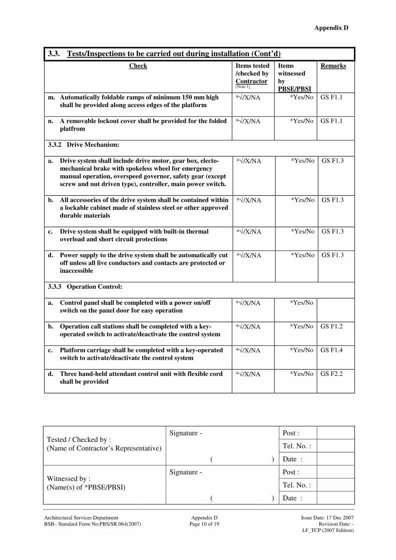
Appendix D
Signature - Post :
Tel. No. :
Tested / Checked by : (Name of Contractor’s Representative)
( ) Date :
Signature - Post :
Tel. No. :
Witnessed by : (Name(s) of *PBSE/PBSI)
( ) Date : Architectural Services Department Appendix D Issue Date: 17 Dec 2007 BSB– Standard Form No:PBS/SR.064(2007) Page 10 of 19 Revision Date: - LF_TCP (2007 Edition)
3.3. Tests/Inspections to be carried out during installation (Cont’d) Check Items tested
/checked by Contractor (Note 1)
Items witnessed by PBSE/PBSI
Remarks
m. Automatically foldable ramps of minimum 150 mm high shall be provided along access edges of the platform
*√/X/NA
*Yes/No GS F1.1
n. A removable lockout cover shall be provided for the folded platfrom
*√/X/NA
*Yes/No GS F1.1
3.3.2 Drive Mechanism: a. Drive system shall include drive motor, gear box, electo-
mechanical brake with spokeless wheel for emergency manual operation, overspeed governor, safety gear (except screw and nut driven type), controller, main power switch.
*√/X/NA
*Yes/No GS F1.3
b. All accessories of the drive system shall be contained within a lockable cabinet made of stainless steel or other approved durable materials
*√/X/NA
*Yes/No GS F1.3
c. Drive system shall be equipped with built-in thermal overload and short circuit protections
*√/X/NA
*Yes/No GS F1.3
d. Power supply to the drive system shall be automatically cut off unless all live conductors and contacts are protected or inaccessible
*√/X/NA
*Yes/No GS F1.3
3.3.3 Operation Control: a. Control panel shall be completed with a power on/off
switch on the panel door for easy operation
*√/X/NA
*Yes/No
b. Operation call stations shall be completed with a key-operated switch to activate/deactivate the control system
*√/X/NA
*Yes/No GS F1.2
c. Platform carriage shall be completed with a key-operated switch to activate/deactivate the control system
*√/X/NA
*Yes/No GS F1.4
d. Three hand-held attendant control unit with flexible cord shall be provided
*√/X/NA
*Yes/No GS F2.2
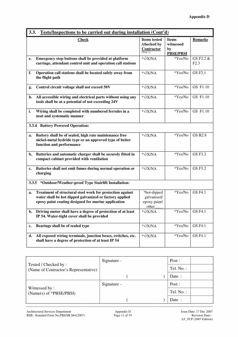
Appendix D
Signature - Post :
Tel. No. :
Tested / Checked by : (Name of Contractor’s Representative)
( ) Date :
Signature - Post :
Tel. No. :
Witnessed by : (Name(s) of *PBSE/PBSI)
( ) Date : Architectural Services Department Appendix D Issue Date: 17 Dec 2007 BSB– Standard Form No:PBS/SR.064(2007) Page 11 of 19 Revision Date: - LF_TCP (2007 Edition)
3.3. Tests/Inspections to be carried out during installation (Cont’d) Check Items tested
/checked by Contractor (Note 1)
Items witnessed by PBSE/PBSI
Remarks
e. Emergency stop buttons shall be provided at platform carriage, attendant control unit and operation call stations
*√/X/NA
*Yes/No GS F2.2 & F2.3
f. Operation call stations shall be located safely away from the flight path
*√/X/NA
*Yes/No GS F2.1
g. Control circuit voltage shall not exceed 50V
*√/X/NA
*Yes/No GS F1.10
h. All accessible wiring and electrical parts without using any tools shall be at a potential of not exceeding 24V
*√/X/NA
*Yes/No GS F1.10
i. Wiring shall be completed with numbered ferrules in a neat and systematic manner
*√/X/NA
*Yes/No GS F1.10
3.3.4 Battery Powered Operation:
a. Battery shall be of sealed, high rate maintenance free nickel-metal hydride type or an approved type of better function and performance
*√/X/NA
*Yes/No GS B2.8
b. Batteries and automatic charger shall be securely fitted in compact cabinet provided with ventilation
*√/X/NA
*Yes/No GS F3.2
c. Batteries shall not emit fumes during normal operation or charging
*√/X/NA
*Yes/No GS F3.2
3.3.5 *Outdoor/Weather-proof Type Stairlift Installation: a. Treatment of structural steel work for protection against
water shall be hot dipped galvanized or factory applied epoxy paint coating designed for marine application
*hot-dipped galvanised/
epoxy paint/ other____
*Yes/No GS F4.1
b. Driving motor shall have a degree of protection of at least IP 54. Water-tight cover shall be provided
*√/X/NA
*Yes/No GS F4.1
c. Bearings shall be of sealed type
*√/X/NA
*Yes/No GS F4.1
d. All exposed wiring terminals, junction boxes, switches, etc. shall have a degree of protection of at least IP 54
*√/X/NA
*Yes/No GS F4.1
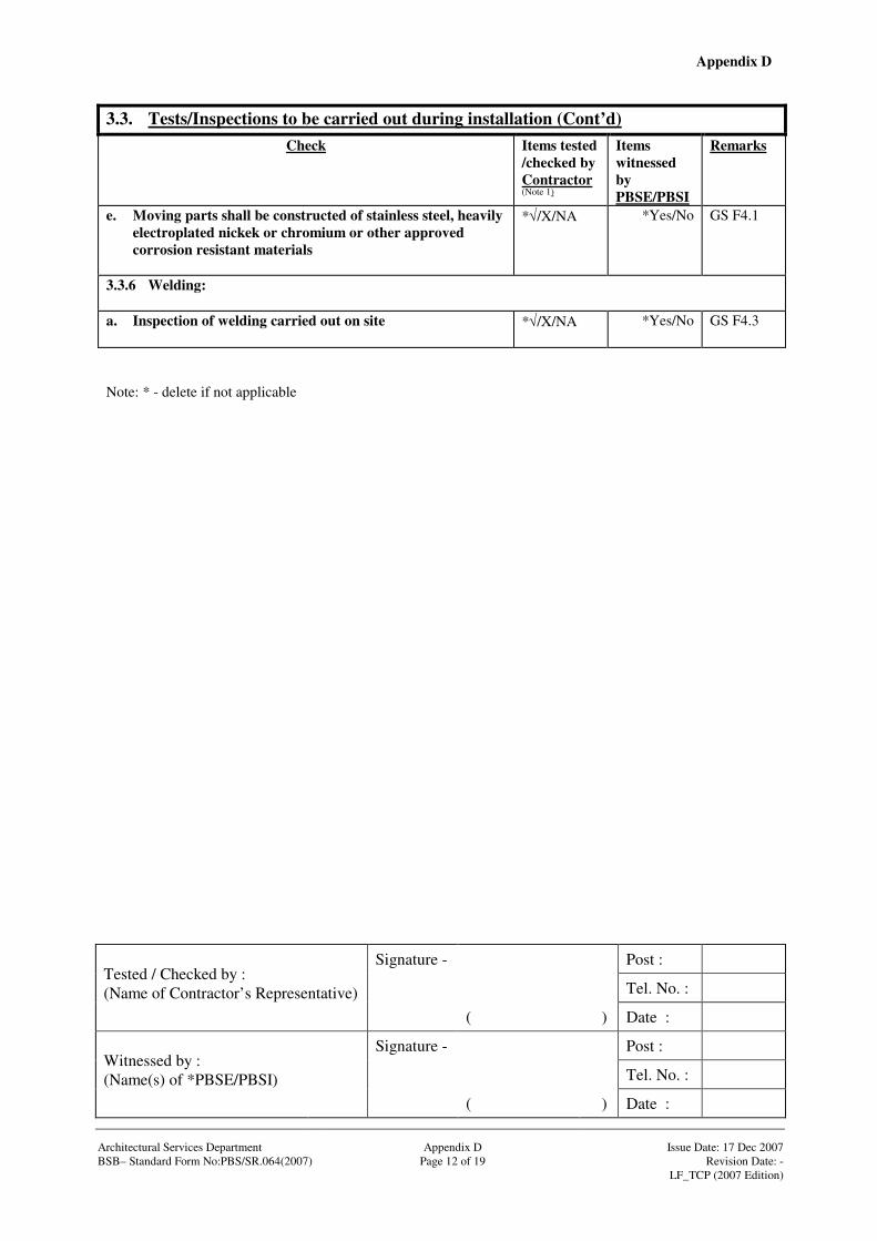
Appendix D
Signature - Post :
Tel. No. :
Tested / Checked by : (Name of Contractor’s Representative)
( ) Date :
Signature - Post :
Tel. No. :
Witnessed by : (Name(s) of *PBSE/PBSI)
( ) Date : Architectural Services Department Appendix D Issue Date: 17 Dec 2007 BSB– Standard Form No:PBS/SR.064(2007) Page 12 of 19 Revision Date: - LF_TCP (2007 Edition)
3.3. Tests/Inspections to be carried out during installation (Cont’d) Check Items tested
/checked by Contractor (Note 1)
Items witnessed by PBSE/PBSI
Remarks
e. Moving parts shall be constructed of stainless steel, heavily electroplated nickek or chromium or other approved corrosion resistant materials
*√/X/NA
*Yes/No GS F4.1
3.3.6 Welding:
a. Inspection of welding carried out on site
*√/X/NA
*Yes/No GS F4.3
Note: * - delete if not applicable
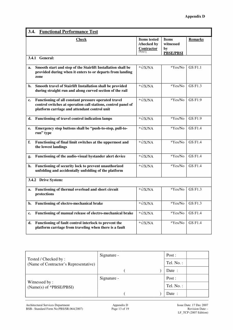
Appendix D
Signature - Post :
Tel. No. :
Tested / Checked by : (Name of Contractor’s Representative)
( ) Date :
Signature - Post :
Tel. No. :
Witnessed by : (Name(s) of *PBSE/PBSI)
( ) Date : Architectural Services Department Appendix D Issue Date: 17 Dec 2007 BSB– Standard Form No:PBS/SR.064(2007) Page 13 of 19 Revision Date: - LF_TCP (2007 Edition)
3.4. Functional Performance Test
Check Items tested /checked by Contractor (Note1)
Items witnessed by PBSE/PBSI
Remarks
3.4.1 General: a. Smooth start and stop of the Stairlift Installation shall be
provided during when it enters to or departs from landing zone
*√/X/NA
*Yes/No GS F1.1
b. Smooth travel of Stairlift Installation shall be provided during straight run and along curved section of the rail
*√/X/NA
*Yes/No GS F1.3
c. Functioning of all constant pressure operated travel control switches at operation call stations, control panel of platform carriage and attendant control unit
*√/X/NA
*Yes/No GS F1.9
d. Functioning of travel control indication lamps *√/X/NA
*Yes/No GS F1.9
e. Emergency stop buttons shall be “push-to-stop, pull-to-run” type
*√/X/NA
*Yes/No GS F1.4
f. Functioning of final limit switches at the uppermost and the lowest landings
*√/X/NA
*Yes/No GS F1.4
g. Functioning of the audio-visual bystander alert device
*√/X/NA
*Yes/No GS F1.4
h. Functioning of security lock to prevent unauthorized unfolding and accidentally unfolding of the platform
*√/X/NA
*Yes/No GS F1.4
3.4.2 Drive System: a. Functioning of thermal overload and short circuit
protections
*√/X/NA
*Yes/No GS F1.3
b. Functioning of electro-mechanical brake *√/X/NA
*Yes/No GS F1.3
c. Functioning of manual release of electro-mechanical brake
*√/X/NA
*Yes/No GS F1.4
d. Functioning of fault control interlock to prevent the platform carriage from traveling when there is a fault
*√/X/NA
*Yes/No GS F1.4
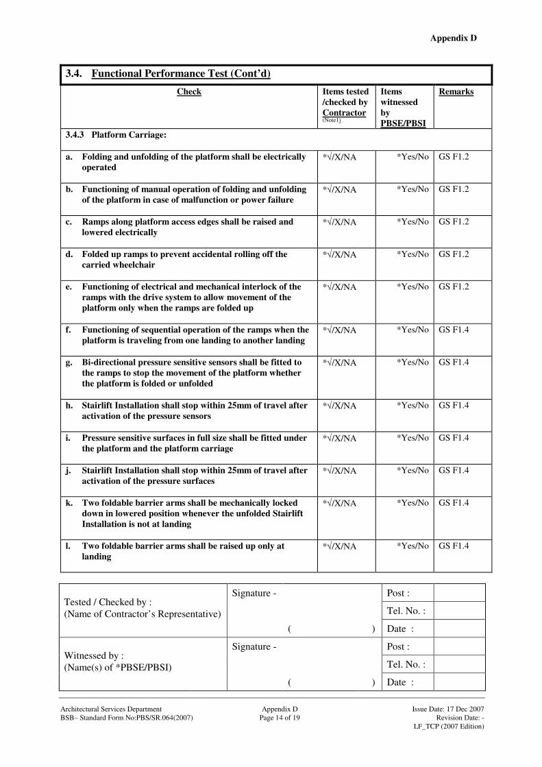
Appendix D
Signature - Post :
Tel. No. :
Tested / Checked by : (Name of Contractor’s Representative)
( ) Date :
Signature - Post :
Tel. No. :
Witnessed by : (Name(s) of *PBSE/PBSI)
( ) Date : Architectural Services Department Appendix D Issue Date: 17 Dec 2007 BSB– Standard Form No:PBS/SR.064(2007) Page 14 of 19 Revision Date: - LF_TCP (2007 Edition)
3.4. Functional Performance Test (Cont’d)
Check Items tested /checked by Contractor (Note1)
Items witnessed by PBSE/PBSI
Remarks
3.4.3 Platform Carriage: a. Folding and unfolding of the platform shall be electrically
operated
*√/X/NA
*Yes/No GS F1.2
b. Functioning of manual operation of folding and unfolding of the platform in case of malfunction or power failure
*√/X/NA
*Yes/No GS F1.2
c. Ramps along platform access edges shall be raised and lowered electrically
*√/X/NA
*Yes/No GS F1.2
d. Folded up ramps to prevent accidental rolling off the carried wheelchair
*√/X/NA
*Yes/No GS F1.2
e. Functioning of electrical and mechanical interlock of the ramps with the drive system to allow movement of the platform only when the ramps are folded up
*√/X/NA
*Yes/No GS F1.2
f. Functioning of sequential operation of the ramps when the platform is traveling from one landing to another landing
*√/X/NA
*Yes/No GS F1.4
g. Bi-directional pressure sensitive sensors shall be fitted to the ramps to stop the movement of the platform whether the platform is folded or unfolded
*√/X/NA
*Yes/No GS F1.4
h. Stairlift Installation shall stop within 25mm of travel after activation of the pressure sensors
*√/X/NA
*Yes/No GS F1.4
i. Pressure sensitive surfaces in full size shall be fitted under the platform and the platform carriage
*√/X/NA
*Yes/No GS F1.4
j. Stairlift Installation shall stop within 25mm of travel after activation of the pressure surfaces
*√/X/NA
*Yes/No GS F1.4
k. Two foldable barrier arms shall be mechanically locked down in lowered position whenever the unfolded Stairlift Installation is not at landing
*√/X/NA
*Yes/No GS F1.4
l. Two foldable barrier arms shall be raised up only at landing
*√/X/NA
*Yes/No GS F1.4

Appendix D
Signature - Post :
Tel. No. :
Tested / Checked by : (Name of Contractor’s Representative)
( ) Date :
Signature - Post :
Tel. No. :
Witnessed by : (Name(s) of *PBSE/PBSI)
( ) Date : Architectural Services Department Appendix D Issue Date: 17 Dec 2007 BSB– Standard Form No:PBS/SR.064(2007) Page 15 of 19 Revision Date: - LF_TCP (2007 Edition)
3.4. Functional Performance Test (Cont’d)
Check Items tested /checked by Contractor (Note 1)
Items witnessed by PBSE/PBSI
Remarks
m. Functioning of emergency stop button on platform carriage
*√/X/NA
*Yes/No GS F2
n. Functioning of the key-operated switch on platform carriage to allow operation of travel control
*√/X/NA
*Yes/No GS F1.4
3.4.4 Operation Control (General): a. Functioning of indication lamps on operation call stations
for power on
*√/X/NA
*Yes/No GS F2.1
b. Functioning of indication lamps on operation call stations for activation of operation call station
*√/X/NA
*Yes/No GS F2.1
c. Functioning of indication lamps on operation call stations for fault signal
*√/X/NA
*Yes/No GS F2.1
d. Functioning of indication lamps on operation call stations for position of platform carriage*
*√/X/NA
*Yes/No GS F2.1
e. Functioning of constant pressure operated control switches on operation call stations for folding and unfolding of platform
*√/X/NA
*Yes/No GS F2.1
f. Functioning of constant pressure operated control switches on operation call stations for calling and sending of platform carriage*
*√/X/NA
*Yes/No GS F2.1
g. Functioning of emergency stop button on operation call stations and platform carriage
*√/X/NA
*Yes/No GS F2.2 & F2.3
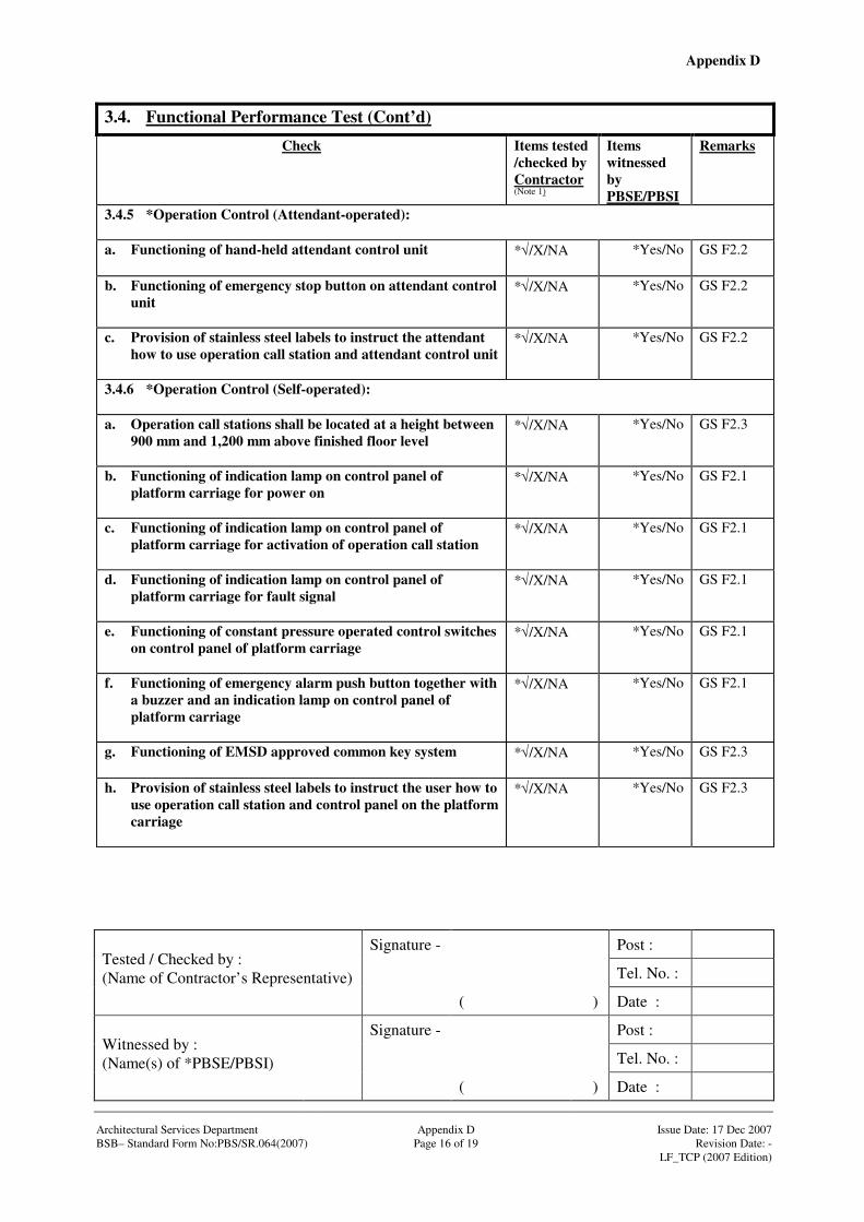
Appendix D
Signature - Post :
Tel. No. :
Tested / Checked by : (Name of Contractor’s Representative)
( ) Date :
Signature - Post :
Tel. No. :
Witnessed by : (Name(s) of *PBSE/PBSI)
( ) Date : Architectural Services Department Appendix D Issue Date: 17 Dec 2007 BSB– Standard Form No:PBS/SR.064(2007) Page 16 of 19 Revision Date: - LF_TCP (2007 Edition)
3.4. Functional Performance Test (Cont’d)
Check Items tested /checked by Contractor (Note 1)
Items witnessed by PBSE/PBSI
Remarks
3.4.5 *Operation Control (Attendant-operated): a. Functioning of hand-held attendant control unit
*√/X/NA
*Yes/No GS F2.2
b. Functioning of emergency stop button on attendant control unit
*√/X/NA
*Yes/No GS F2.2
c. Provision of stainless steel labels to instruct the attendant how to use operation call station and attendant control unit
*√/X/NA
*Yes/No GS F2.2
3.4.6 *Operation Control (Self-operated): a. Operation call stations shall be located at a height between
900 mm and 1,200 mm above finished floor level
*√/X/NA
*Yes/No GS F2.3
b. Functioning of indication lamp on control panel of platform carriage for power on
*√/X/NA
*Yes/No GS F2.1
c. Functioning of indication lamp on control panel of platform carriage for activation of operation call station
*√/X/NA
*Yes/No GS F2.1
d. Functioning of indication lamp on control panel of platform carriage for fault signal
*√/X/NA
*Yes/No GS F2.1
e. Functioning of constant pressure operated control switches on control panel of platform carriage
*√/X/NA
*Yes/No GS F2.1
f. Functioning of emergency alarm push button together with a buzzer and an indication lamp on control panel of platform carriage
*√/X/NA
*Yes/No GS F2.1
g. Functioning of EMSD approved common key system
*√/X/NA
*Yes/No GS F2.3
h. Provision of stainless steel labels to instruct the user how to use operation call station and control panel on the platform carriage
*√/X/NA
*Yes/No GS F2.3

Appendix D
Signature - Post :
Tel. No. :
Tested / Checked by : (Name of Contractor’s Representative)
( ) Date :
Signature - Post :
Tel. No. :
Witnessed by : (Name(s) of *PBSE/PBSI)
( ) Date : Architectural Services Department Appendix D Issue Date: 17 Dec 2007 BSB– Standard Form No:PBS/SR.064(2007) Page 17 of 19 Revision Date: - LF_TCP (2007 Edition)
3.4. Functional Performance Test (Cont’d)
Check Items tested /checked by Contractor (Note 1)
Items witnessed by PBSE/PBSI
Remarks
3.4.7 Fire Emergency Service: a. Functioning of power isolation of Stairlift Installation in
parked position
*√/X/NA
*Yes/No GS F3.1
b. Functioning of full operation of Stairlift Installation located between landings
*√/X/NA
*Yes/No GS F3.1
c. Functioning of automatic switch over between normal and battery supply
*√/X/NA
*Yes/No GS F3.1
3.4.8 Battery Powered Operation: a. Completion of 5 upward and 5 downward continuous
journey under full load without charging
*√/X/NA
*Yes/No GS F3.2
b. *Battery charging shall carry out at each end of guide rail
*√/X/NA
*Yes/No GS F3.2
c. *Indication of out of charging position
*√/X/NA
*Yes/No GS F3.2
Note: * - delete if not applicable
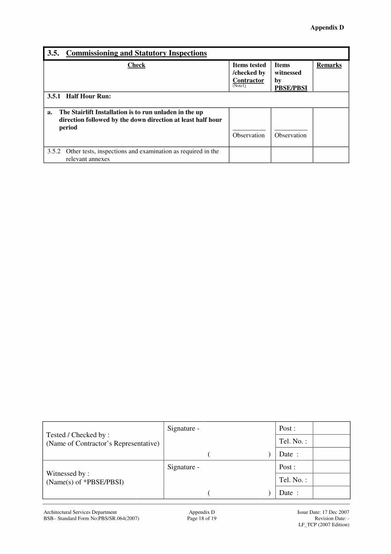
Appendix D
Signature - Post :
Tel. No. :
Tested / Checked by : (Name of Contractor’s Representative)
( ) Date :
Signature - Post :
Tel. No. :
Witnessed by : (Name(s) of *PBSE/PBSI)
( ) Date : Architectural Services Department Appendix D Issue Date: 17 Dec 2007 BSB– Standard Form No:PBS/SR.064(2007) Page 18 of 19 Revision Date: - LF_TCP (2007 Edition)
3.5. Commissioning and Statutory Inspections Check Items tested
/checked by Contractor (Note1)
Items witnessed by PBSE/PBSI
Remarks
3.5.1 Half Hour Run: a. The Stairlift Installation is to run unladen in the up
direction followed by the down direction at least half hour period
__________Observation
__________Observation
3.5.2 Other tests, inspections and examination as required in the relevant annexes
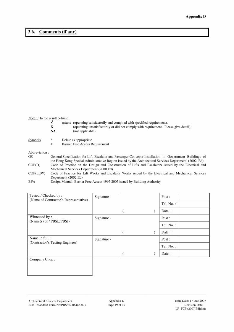
Appendix D
Architectural Services Department
Appendix D
Issue Date: 17 Dec 2007
BSB– Standard Form No:PBS/SR.064(2007) Page 19 of 19 Revision Date: - LF_TCP (2007 Edition)
3.6. Comments (if any)
Note 1: In the result column, √√√√ means (operating satisfactorily and complied with specified requirement). X (operating unsatisfactorily or did not comply with requirement. Please give detail), NA (not applicable) Symbols : * Delete as appropriate # Barrier Free Access Requirement Abbreviation : GS General Specification for Lift, Escalator and Passenger Conveyor Installation in Government Buildings of
the Hong Kong Special Administrative Region issued by the Architectural Services Department (2002 Ed) COP(D) Code of Practice on the Design and Construction of Lifts and Escalators issued by the Electrical and
Mechanical Services Department (2000 Ed) COP(LEW) Code of Practice for Lift Works and Escalator Works issued by the Electrical and Mechanical Services
Department (2002 Ed) BFA Design Manual: Barrier Free Access 1997 2005 issued by Building Authority
Signature - Post :
Tel. No. :
Tested / Checked by : (Name of Contractor’s Representative)
( ) Date :
Signature - Post :
Tel. No. :
Witnessed by : (Name(s) of *PBSE/PBSI)
( ) Date :
Signature - Post :
Tel. No. :
Name in full : (Contractor’s Testing Engineer)
( ) Date :
Company Chop :
Annex A Test and Examination Report for Electric Passenger Lifts/Freight Lifts/Vehicle Lifts

TEST AND EXAMINATION REPORT FOR ELECTRIC PASSENGER LIFTS*/FREIGHT LIFTS*/ VEHICLE LIFTS*
Architectural Services Department
Annex A
Issue Date: 17 Dec 2007
Page 1 of 6 Revision Date: - LF_TCP (2007 Edition) *Delete whichever not applicable
1. Description of Installation Location Manufacturer Plant No. Lift Identification No. Length of Travel m Levels Served Rated Load kg Person Rated Speed m/s Power Supply at Time of Test Volt Phase Hz Levelling tolerance ± mm Number of Starts /hr Car Floor Area m2 Machine Room Location: above lift well*/below lift well*/at side*/others
Is this a fireman's lift? Yes No Is this lift for persons with a disability? Yes No The model no. and manufacturer of the controller _______________________________________________________________________
__________ 2. Static Examination - Mechanical 2.1 Suspension (a) Suspension Ropes Certificate No. & Date of Issue (i) Number (ii) Nominal Diameter mm (b) Type of Anchorages: Car Counterweight Have the anchorages been examined and found in good working condition Yes No 2.2 Safety Gear Has the safety gear been certified in accordance with 5.11.1 of the Design Code, Part 1? Yes
No Model No.,
_________________________________________________________________ Certificate No. & Date of Issue
2.3 Energy Dissipation Buffers N.A.*/Fitted* (a) Have the buffers been certified in accordance with 6.2.1of the Design Code, Part 1? Yes No (b) Model No.,
____________________________________________________________ Certificate No. & Date of Issue (c) Is the buffer switch functioning properly? Yes No
2.4 Energy Accumulation Buffers N.A.*/Fitted* (a) Have the buffers been certified in accordance with 6.2.1
of the Design Code, Part 1? N.A. Yes No (b) Model No.,
____________________________________________________________ Certificate No. & Date of Issue (c) Do the buffers comply with 6.2.2 of the Design Code, Part 1?
Yes No 2.5 Brake Does the brake sustain the static car, in the lower part of
its travel, with the rated load plus 25% (passenger/general freight lifts) or 50%(vehicle lifts/industrial truck loaded freight lifts)? Yes No
2.6 Overspeed Governor (a) Has the governor been certified in accordance with
5.12.1 of the Design Code, Part 1? Yes No (b) Model No.,
___________________________________________________________ Certificate No. & Date of Issue ___________________________________________ (c) Is the data plate in accordance with 11.6 of the Design Code, Part
1? Yes No (d) Does the governor rope conform to 5.12.6 of the Design Code, Part
1? Yes No
(e) Is the governor rope slack switch working properly? Yes No
2.7 Landing Door Locking Device Has the landing door locking device been certified in accordance with
3.7.3.1 of the Design Code, Part 1? Yes
No Model No.,
_________________________________________________________________ Certificate No. & Date of Issue 2.8 Ascending Car Overspeed Protection Means
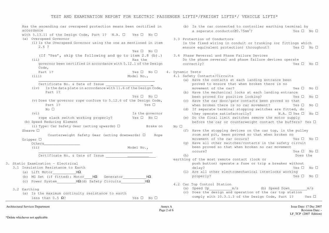
TEST AND EXAMINATION REPORT FOR ELECTRIC PASSENGER LIFTS*/FREIGHT LIFTS*/ VEHICLE LIFTS*
Architectural Services Department
Annex A
Issue Date: 17 Dec 2007
Page 2 of 6 Revision Date: - LF_TCP (2007 Edition) *Delete whichever not applicable
Has the ascending car overspeed protection means been certified in accordance
with 5.13.11 of the Design Code, Part 1? N.A. Yes No (a) Overspeed Governor
(i) Is the Overspeed Governor using the one as mentioned in item 2.6 ?
Yes No (If ‘Yes’, skip the following and go to item 2.8 (b).) (ii) Has the
governor been certified in accordance with 5.12.1 of the Design Code,
Part 1? Yes No (iii) Model No.,
_______________________________________________________ Certificate No. & Date of Issue _ (iv) Is the data plate in accordance with 11.6 of the Design Code,
Part 1? Yes No
(v) Does the governor rope conform to 5.12.6 of the Design Code, Part 1? Yes No
(vi) Is the governor rope slack switch working properly? Yes No
(b) Speed Reducing Element (i) Type: Car Safety Gear (acting upwards) Brake on Sheave Counterweight Safety Gear (acting downwards) Rope Gripper Others_________________
(ii) Model No., ______________________________________________________
Certificate No. & Date of Issue __________ 3. Static Examination - Electrical 3.1 Insulation Resistance to Earth (a) Lift Motor MΩ (b) MG Set (if fitted): Motor MΩ Generator MΩ (c) Power System MΩ(d) Safety Circuits MΩ 3.2 Earthing (a) Is the maximum continuity resistance to earth
less than 0.5 Ω? Yes No
(b) Is the car connected to controller earthing terminal by
a separate conductor≥0.75mm2? Yes No 3.3 Protection of Conductors
Is the fixed wiring in conduit or trunking (or fittings which ensure equivalent protection) throughout? Yes No
3.4 Phase Reversal and Phase Failure Devices
Do the phase reversal and phase failure devices operate correctly? Yes No 4. Dynamic Tests 4.1 Safety Contacts/Circuits (a) Have the contacts at each landing entrance been proved to ensure that when broken there is no movement of the car? Yes No (b) Have the mechanical locks at each landing entrance
been proved for positive locking? Yes No (c) Have the car door/gate contacts been proved so that
when broken there is no car movement? Yes No (d) If separate terminal stopping switches are fitted, do
they operate satisfactorily? N.A. Yes No (e) Do the final limit switches remove the motor supply
before the car or counterweight contact the buffers? Yes No
(f) Have the stopping devices on the car top, in the pulley room and pit, been proved so that when broken no
movement of the car occurs? Yes No (g) Have all other switches/contacts in the safety circuit
been proved so that when broken no car movement occurs? Yes No
(h) Does the earthing of the most remote contact (lock or
push button) operate a fuse or trip a breaker without delay? Yes No
(i) Are all other electromechanical interlocks working properly? Yes No
4.2 Car Top Control Station (a) Speed Up m/s (b) Speed Down m/s (c) Does the design and operation of the car top station
comply with 10.3.1.3 of the Design Code, Part 1? Yes
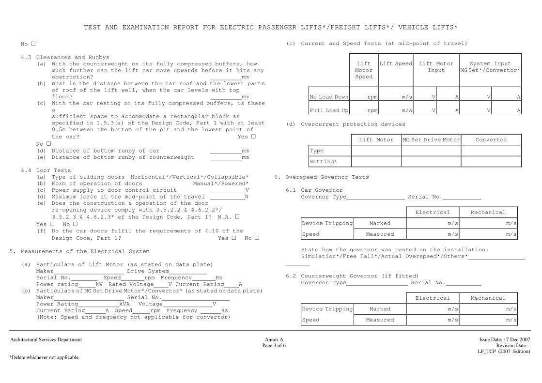
TEST AND EXAMINATION REPORT FOR ELECTRIC PASSENGER LIFTS*/FREIGHT LIFTS*/ VEHICLE LIFTS*
Architectural Services Department
Annex A
Issue Date: 17 Dec 2007
Page 3 of 6 Revision Date: - LF_TCP (2007 Edition) *Delete whichever not applicable
No 4.3 Clearances and Runbys (a) With the counterweight on its fully compressed buffers, how
much further can the lift car move upwards before it hits any obstruction? mm
(b) What is the distance between the car roof and the lowest parts of roof of the lift well, when the car levels with top
floor? mm (c) With the car resting on its fully compressed buffers, is there
a sufficient space to accommodate a rectangular block as specified in 1.5.3(a) of the Design Code, Part 1 with at least
0.5m between the bottom of the pit and the lowest point of the car? Yes No
(d) Distance of bottom runby of car mm (e) Distance of bottom runby of counterweight mm
4.4 Door Tests (a) Type of sliding doors Horizontal*/Vertical*/Collapsible* (b) Form of operation of doors Manual*/Powered* (c) Power supply to door control circuit V (d) Maximum force at the mid-point of the travel N (e) Does the construction & operation of the door
re-opening device comply with 3.5.2.2 & 4.6.2.2*/ 3.5.2.3 & 4.6.2.3* of the Design Code, Part 1? N.A.
Yes No (f) Do the car doors fulfil the requirements of 4.10 of the Design Code, Part 1? Yes No
5. Measurements of the Electrical System (a) Particulars of Lift Motor (as stated on data plate) Maker Drive System
Serial No. Speed rpm Frequency Hz Power rating kW Rated Voltage V Current Rating A (b) Particulars of MG Set Drive Motor*/Convertor* (as stated on data plate)
Maker Serial No. Power Rating kVA Voltage V Current Rating A Speed rpm Frequency Hz (Note: Speed and frequency not applicable for convertor)
(c) Current and Speed Tests (at mid-point of travel)
Lift Motor Speed
Lift Speed
Lift Motor
Input
System Input
MG Set*/Convertor*
No Load Down
rpm
m/s
V
A
V
A
Full Load Up
rpm
m/s
V
A
V
A
(d) Overcurrent protection devices
Lift Motor MG Set Drive Motor Convertor
Type
Settings
6. Overspeed Governor Tests 6.1 Car Governor Governor Type Serial No.
Electrical Mechanical
Device Tripping Marked m/s m/s
Speed Measured m/s m/s
State how the governor was tested on the installation:
Simulation*/Free Fall*/Actual Overspeed*/Others*
6.2 Counterweight Governor (if fitted) Governor Type Serial No.
Electrical Mechanical
Device Tripping Marked m/s m/s
Speed Measured m/s m/s

TEST AND EXAMINATION REPORT FOR ELECTRIC PASSENGER LIFTS*/FREIGHT LIFTS*/ VEHICLE LIFTS*
Architectural Services Department
Annex A
Issue Date: 17 Dec 2007
Page 4 of 6 Revision Date: - LF_TCP (2007 Edition) *Delete whichever not applicable
State how the governor was tested on the installation:
Simulation*/Free Fall*/Actual Overspeed*/Others*
7. Car Safety Gear Tests Note: The following tests should be conducted with the car descending, with the brake open and the machine continuing to run till the ropes slip or become slack. (a) Progressive Type N.A.*/Fitted* (i) Does the safety gear operate correctly when engaging
at rated speed with the rated load uniformly distributed in the lift car? N.A. Yes No
OR (ii) Does the safety gear operate correctly when engaging at
levelling or inspection speed with 125%*/150%* of the rated load uniformly distributed in the lift car? N.A. Yes No State the speed m/s
(b) Instantaneous Type N.A.*/Fitted* Does the safety gear operate correctly when engaging at rated speed with the rated load uniformly distributed? Yes
No (c) What was the stopping distance in the test? m (d) After the lift car was brought to a halt in the above test was
the floor horizontal, or sloping less than 5% from the horizontal? Yes No
8. Counterweight Safety Gear Tests Note: The following tests should be conducted with the counterweight
descending, with the brake open and the machine continuing to run till the ropes slip or become slack. (a) Progressive Type N.A.*/Fitted* (i) Does the safety gear operate correctly when engaging
at rated speed with the car empty? N.A. Yes No OR
(ii) Does the safety gear operate correctly when engaging at levelling or inspection speed with the car empty? N.A. Yes No (b) Instantaneous Type
N.A.*/Fitted* Does the safety gear operate correctly when engaging at
rated speed with the car empty? Yes No 9. Ascending Car Overspeed Protection Means Tests 9.1. Overspeed Governor Tests
(a) Car Governor Governor Type Serial No.
Electrical Mechanical
Device Tripping Marked m/s m/s
Speed (upward) Measured m/s m/s
State how the governor was tested on the installation: Simulation*/ /Actual Overspeed*/Others*
(b) Counterweight Governor (if fitted) Governor Type Serial No.
Electrical Mechanical
Device Tripping Marked m/s m/s
Speed (downward)
Measured m/s m/s
State how the governor was tested on the installation: Simulation*/Actual Overspeed*/Others*
9.2. Speed Reducing Element Tests
(a) Car Safety Gear (if fitted)
The test should be conducted with the car ascending and the brake open.
(i) Does the safety gear operate correctly when engaging at preset
speed with the car empty? Yes No State the measured speed m/s
(ii) What was the stopping distance in the test? m

TEST AND EXAMINATION REPORT FOR ELECTRIC PASSENGER LIFTS*/FREIGHT LIFTS*/ VEHICLE LIFTS*
Architectural Services Department
Annex A
Issue Date: 17 Dec 2007
Page 5 of 6 Revision Date: - LF_TCP (2007 Edition) *Delete whichever not applicable
(iiI) What was the deceleration in the test? ___________m/s2 (b) Counterweight Safety Gear (if fitted)
The test should be conducted with the car ascending and the brake open. (i) Does the safety gear operate correctly when engaging at preset
speed with the car empty? Yes No State the measured speed m/s (ii) What was the stopping distance in the test? m (ii) What was the deceleration in the test? ___________m/s2
(c) Rope Gripper (if fitted) The test should be conducted with the car ascending and the brake open. (i) Does the rope gripper operate correctly when engaging at preset
speed with the car empty? Yes No State the measured speed m/s (ii) What was the stopping distance in the test? m (iiI) What was the deceleration in the test? ____________m/s2
(d) Brake on Sheave (if fitted) The test should be conducted with the car ascending. (i) Does the brake on sheave operate correctly when engaging at preset
speed with the car empty? Yes No State the measured speed m/s
(ii) What was the stopping distance in the test? m
(iiI) What was the deceleration in the test? ____________m/s2
10. Buffer Tests
(a) For Car Buffers (i) When the car was brought into contact with the buffers at rated load at rated speed, or at a speed for which the stroke of the buffers has been calculated, was the operation satisfactory? Yes No (ii) Do the buffers recover automatically after operation? Yes
No (b) For Counterweight Buffers When the counterweight was brought into contact with the buffers with the car empty at rated speed, or a speed for which the stroke of the buffers has been calculated, was the operation satisfactory? Yes No 11. Traction Checks (a) Does the car stop under emergency conditions (i) with the car empty when travelling upwards
at rated speed? Yes No (ii) with the rated load plus 25% when travelling
downwards in the lower part of the lift well at rated speed? Yes No
(b) With the counterweight resting on its fully compressed buffers, is it impossible for the empty car to be raised
under power? Yes No 12. Emergency Stopping Distance What was the stopping distance of the car travelling in down
direction at rated speed and carrying 125% of the rated load under emergency stopping conditions? m
13. Duty Cycle Test Does the lift operate satisfactorily for a period of at least 0.5
hour when running with rated load, full travel and intermediate stops at a rate of starts equal to the number of starts per hour recommended in Item 1? Yes No
14. General (Lift Work) (a) Is the maximum load indicated in the car and does it comply
with 11.2.1 of the Design Code, Part 1? Yes No
(b) Does the fireman's lift operation function correctly? N.A. Yes No
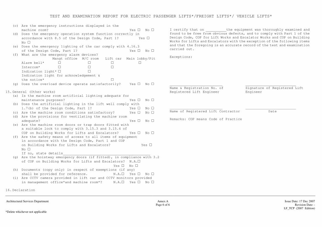
TEST AND EXAMINATION REPORT FOR ELECTRIC PASSENGER LIFTS*/FREIGHT LIFTS*/ VEHICLE LIFTS*
Architectural Services Department
Annex A
Issue Date: 17 Dec 2007
Page 6 of 6 Revision Date: - LF_TCP (2007 Edition) *Delete whichever not applicable
(c) Are the emergency instructions displayed in the machine room? Yes No
(d) Does the emergency operation system function correctly in accordance with 8.5 of the Design Code, Part 1? Yes No
(e) Does the emergency lighting of the car comply with 4.16.3 of the Design Code, Part 1? Yes No
(f) What are the emergency alarm devices? Mangt office M/C room Lift car Main lobby/Pit
Alarm bell* Intercom* Indication light* Indication light for acknowledgement & the notice*
(g) Does the overload device operate satisfactorily? Yes No 15. General (Other works) (a) Is the machine room artificial lighting adequate for
maintenance purposes? Yes No (b) Does the artificial lighting in the lift well comply with
1.7(b) of the Design Code, Part 1? Yes No (c) Are the machine room conditions satisfactory? Yes No (d) Are the provisions for ventilating the machine room
adequate? Yes No (e) Are the machine room doors or trap doors fitted with
a suitable lock to comply with 3.15.3 and 3.15.4 of COP on Building Works for Lifts and Escalators? Yes No
(f) Are the safety means of access to all items of equipment in accordance with the Design Code, Part 1 and COP
on Building Works for Lifts and Escalators? Yes No
If no, state details (g) Are the hoistway emergency doors (if fitted), in compliance with 3.2
of COP on Building Works for Lifts and Escalators? N.A. Yes No
(h) Documents (copy only) in respect of exemptions (if any) shall be provided for reference. N.A. Yes No
(i) Are CCTV camera provided in lift car and CCTV monitors provided in management office*and machine room*? N.A. Yes No
16. Declaration
I certify that on the equipment was thoroughly examined and
found to be free from obvious defects, and to comply with Part 1 of the Design Code, COP for Lift Works and Escalator Works and COP on Building Works for Lifts and Escalators with the exception of the following items and that the foregoing is an accurate record of the test and examination carried out.
Exceptions:
Name & Registration No. of Signature of Registered Lift Registered Lift Engineer Engineer
Name of Registered Lift Contractor Date Remarks: COP means Code of Practice
Annex B Test and Examination Report for Hydraulic Passenger Lifts/Freight Lifts/Vehicle Lifts

TEST AND EXAMINATION REPORT FOR HYDRAULIC PASSENGER LIFTS*/FREIGHT LIFTS*/ VEHICLE LIFTS*
Architectural Services Department
Annex B
Issue Date: 17 Dec 2007
Page 1 of 5 Revision Date: - LF_TCP (2007 Edition) *Delete whichever not applicable
1. Description of Installation Location Manufacturer Plant No. Lift Identification No. Length of Travel
m Levels Served Rated Load kg Persons Rated Speed Up
m/s Dia. of Ram m Ram Action: Direct*/Indirect* Type of Ram:
Single*/Telescopic* Power Supply at Time of Test Volt Phase Hz
Levelling tolerance ± mm Number of Starts /hr Car Floor Area m2 Machine Room Location:above lift well*/below lift well*/at side*/Others
Is this a fireman's lift? Yes No Is this lift for persons with a disability? Yes No
Devices provided against free fall and descent with excessive speed of the car:- (i) Safety gear tripped by overspeed governor Yes No (ii) Safety gear
tripped by failure of suspension gear or by safety rope Yes No (iii) Rupture valve
Yes No (iv) Restrictor
Yes No Devices/systems provided against creeping of the car:- (i) Safety gear tripped by downward movement of the car Yes No (ii) Pawl device
Yes No (iii) Clamping
device Yes No (iv) Electrical
anti-creep system Yes No
2. Static Examination - Mechanical 2.1 Jack Single Jack Multi Jack Number of Jacks In multi jack system, are the jacks, in compliance
with 8.1.3 of the Design Code, Part 2? N.A. Yes No 2.2 Suspension (a) Suspension Ropes (i) Certificate No. & Date of Issue (ii) Number Nominal Diameter mm (b) Type of Anchorage: Car Counterweight (if provided) Have the anchorages been examined and found in good
working condition? Yes No
2.3 Suspension Chains
N.A.*/Fitted* (a) Number (b) Pitch mm (c) Type and Construction 2.4 Safety Gear
N.A.*/Fitted* Has the safety gear been certified in accordance with 5.10.1.5 of the Design Code, Part 2? Yes No Model No.,
_________________________________________________________________ Certificate No. & Date of Issue _______________
2.5 Energy Dissipation Buffers N.A.*/Fitted*
(a) Have the buffers been certified in accordance with F5 of BS5655, Part 2? Yes
No (b) Model No.,
____________________________________________________________ Certificate No. & Date of Issue ____________ (c) Is the buffer switch functioning properly? Yes No 2.6 Energy Accumulation Buffers
N.A.*/Fitted* (a) Have the buffers been certified in accordance with
F5 of BS5655 Part 2? N.A. Yes No (b) Do the buffers comply with 6.2.3 of the Design Code, Part 2?
Yes No 2.7 Overspeed Governor
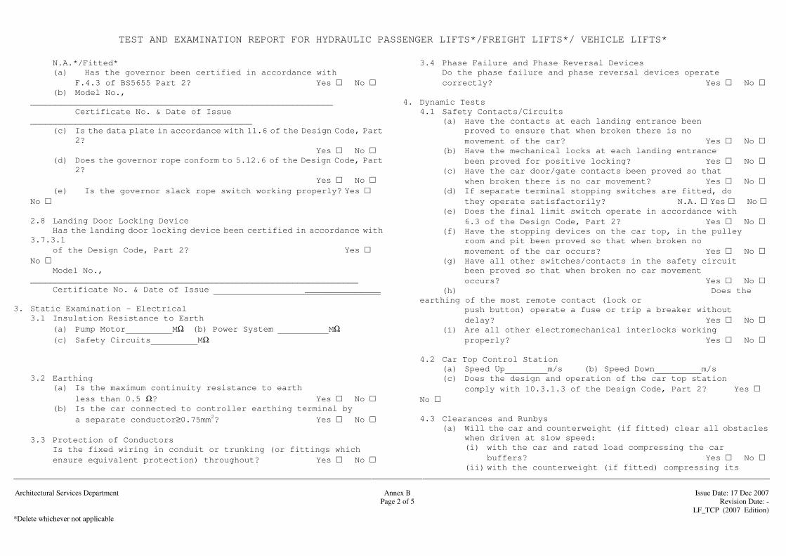
TEST AND EXAMINATION REPORT FOR HYDRAULIC PASSENGER LIFTS*/FREIGHT LIFTS*/ VEHICLE LIFTS*
Architectural Services Department
Annex B
Issue Date: 17 Dec 2007
Page 2 of 5 Revision Date: - LF_TCP (2007 Edition) *Delete whichever not applicable
N.A.*/Fitted* (a) Has the governor been certified in accordance with
F.4.3 of BS5655 Part 2? Yes No (b) Model No.,
____________________________________________________________ Certificate No. & Date of Issue
____________________________________________ (c) Is the data plate in accordance with 11.6 of the Design Code, Part
2? Yes No (d) Does the governor rope conform to 5.12.6 of the Design Code, Part
2? Yes No
(e) Is the governor slack rope switch working properly? Yes No
2.8 Landing Door Locking Device Has the landing door locking device been certified in accordance with
3.7.3.1 of the Design Code, Part 2? Yes
No Model No.,
_________________________________________________________________ Certificate No. & Date of Issue _______________ 3. Static Examination - Electrical 3.1 Insulation Resistance to Earth (a) Pump Motor MΩ (b) Power System MΩ (c) Safety Circuits MΩ 3.2 Earthing (a) Is the maximum continuity resistance to earth
less than 0.5 Ω? Yes No (b) Is the car connected to controller earthing terminal by
a separate conductor≥0.75mm2? Yes No 3.3 Protection of Conductors
Is the fixed wiring in conduit or trunking (or fittings which ensure equivalent protection) throughout? Yes No
3.4 Phase Failure and Phase Reversal Devices Do the phase failure and phase reversal devices operate correctly? Yes No 4. Dynamic Tests 4.1 Safety Contacts/Circuits (a) Have the contacts at each landing entrance been proved to ensure that when broken there is no movement of the car? Yes No (b) Have the mechanical locks at each landing entrance
been proved for positive locking? Yes No (c) Have the car door/gate contacts been proved so that
when broken there is no car movement? Yes No (d) If separate terminal stopping switches are fitted, do
they operate satisfactorily? N.A. Yes No (e) Does the final limit switch operate in accordance with 6.3 of the Design Code, Part 2? Yes No (f) Have the stopping devices on the car top, in the pulley
room and pit been proved so that when broken no movement of the car occurs? Yes No (g) Have all other switches/contacts in the safety circuit
been proved so that when broken no car movement occurs? Yes No
(h) Does the earthing of the most remote contact (lock or
push button) operate a fuse or trip a breaker without delay? Yes No
(i) Are all other electromechanical interlocks working properly? Yes No
4.2 Car Top Control Station (a) Speed Up m/s (b) Speed Down m/s (c) Does the design and operation of the car top station
comply with 10.3.1.3 of the Design Code, Part 2? Yes No
4.3 Clearances and Runbys
(a) Will the car and counterweight (if fitted) clear all obstacles when driven at slow speed: (i) with the car and rated load compressing the car buffers? Yes No (ii) with the counterweight (if fitted) compressing its
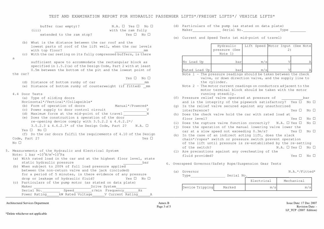
TEST AND EXAMINATION REPORT FOR HYDRAULIC PASSENGER LIFTS*/FREIGHT LIFTS*/ VEHICLE LIFTS*
Architectural Services Department
Annex B
Issue Date: 17 Dec 2007
Page 3 of 5 Revision Date: - LF_TCP (2007 Edition) *Delete whichever not applicable
buffer (car empty)? N.A. Yes No (iii) with the ram fully
extended to the ram stop? Yes No
(b) What is the distance between the car roof and the lowest parts of roof of the lift well, when the car levels with top floor? mm (c) With the car resting on its fully compressed buffers, is there
a sufficient space to accommodate the rectangular block as specified in 1.5.2(a) of the Design Code, Part 2 with at least
0.5m between the bottom of the pit and the lowest point of the car?
Yes No (d) Distance of bottom runby of car mm (e) Distance of bottom runby of counterweight (if fitted) mm 4.4 Door Tests (a) Type of sliding doors
Horizontal*/Vertical*/Collapsible* (b) Form of operation of doors Manual*/Powered* (c) Power supply to door control circuit V (d) Maximum force at the mid-point of the travel N (e) Does the construction & operation of the door
re-opening device comply with 3.5.2.2 & 4.6.2.2*/ 3.5.2.3 & 4.6.2.3* of the Design Code, Part 2? N.A.
Yes No (f) Do the car doors fulfil the requirements of 4.10 of the Design
Code, Part 2? Yes No
5. Measurements of the Hydraulic and Electrical System Note: 1 bar =105N/m2=105Pa (a) With rated load in the car and at the highest floor level, state
static hydraulic pressure bar (b) When subject to 200% of full load pressure applied
between the non-return valve and the jack (included) for a period of 5 minutes, is there evidence of any pressure
drop or leakage of hydraulic fluid? Yes No (c) Particulars of the pump motor (as stated on data plate) Maker Drive System
Serial No. Speed r/min Frequency Hz Power Rating kW Rated Voltage V Current Rating A
(d) Particulars of the pump (as stated on data plate) Maker Serial No. Type (e) Current and Speed Tests (at mid-point of travel)
Hydraulic pressure (See
Note 1)
Lift Speed Motor Input (See Note 2)
No Load Up
bar
m/s
V
A
Rated Load Up
bar
m/s
V
A
Note 1 - The pressure readings should be taken between the check valve, or down direction valve, and the supply line to the cylinder.
Note 2 - The motor current readings on conductors adjacent to the motor terminal block should be taken with the motor running steadily.
(f) Pressure relief valve operated at pressure of bar and is the integrity of the pipework satisfactory? Yes No (g) Is the relief valve secured against any unauthorized interference? Yes No (h) Does the check valve hold the car with rated load at
floor level? Yes No (i) Does the rupture valve function correctly? N.A. Yes No (j) Does the operation of the manual lowering valve lower the
car at a slow speed not exceeding 0.3m/s? Yes No (k) In the case of an indirect acting lift, does the slack
chain*/ropes* switch or pressure switch prevent operation of the lift until pressure is re-established by the re-setting
of the switch? N.A. Yes No (l) Are precautions against any overheating of the fluid provided? Yes No 6. Overspeed Governor/Safety Rope/Suspension Gear Tests (a) Governor N.A.*/Fitted* Type Serial No.
Electrical Mechanical
Device Tripping Marked m/s m/s
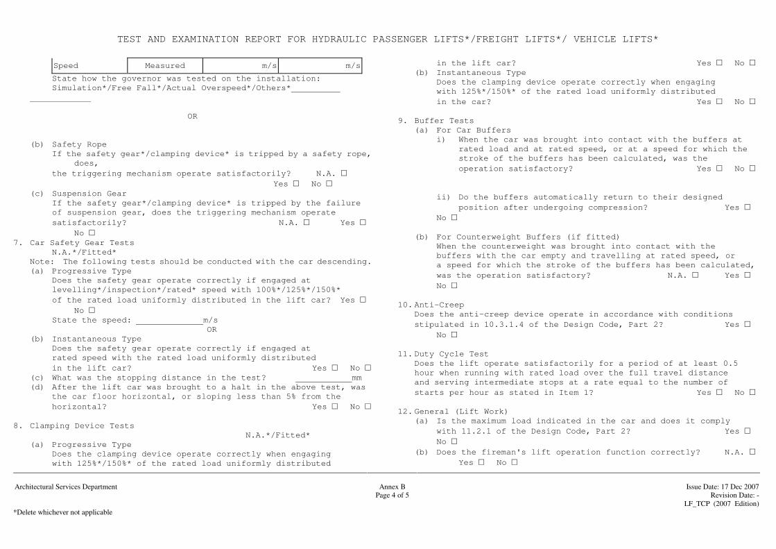
TEST AND EXAMINATION REPORT FOR HYDRAULIC PASSENGER LIFTS*/FREIGHT LIFTS*/ VEHICLE LIFTS*
Architectural Services Department
Annex B
Issue Date: 17 Dec 2007
Page 4 of 5 Revision Date: - LF_TCP (2007 Edition) *Delete whichever not applicable
Speed Measured m/s m/s
State how the governor was tested on the installation: Simulation*/Free Fall*/Actual Overspeed*/Others*
OR
(b) Safety Rope If the safety gear*/clamping device* is tripped by a safety rope,
does, the triggering mechanism operate satisfactorily? N.A.
Yes No (c) Suspension Gear If the safety gear*/clamping device* is tripped by the failure of suspension gear, does the triggering mechanism operate satisfactorily? N.A. Yes
No 7. Car Safety Gear Tests
N.A.*/Fitted* Note: The following tests should be conducted with the car descending. (a) Progressive Type Does the safety gear operate correctly if engaged at
levelling*/inspection*/rated* speed with 100%*/125%*/150%* of the rated load uniformly distributed in the lift car? Yes
No State the speed: m/s
OR (b) Instantaneous Type
Does the safety gear operate correctly if engaged at rated speed with the rated load uniformly distributed in the lift car? Yes No
(c) What was the stopping distance in the test? mm (d) After the lift car was brought to a halt in the above test, was
the car floor horizontal, or sloping less than 5% from the horizontal? Yes No
8. Clamping Device Tests N.A.*/Fitted*
(a) Progressive Type Does the clamping device operate correctly when engaging
with 125%*/150%* of the rated load uniformly distributed
in the lift car? Yes No (b) Instantaneous Type Does the clamping device operate correctly when engaging with 125%*/150%* of the rated load uniformly distributed in the car? Yes No 9. Buffer Tests (a) For Car Buffers i) When the car was brought into contact with the buffers at rated load and at rated speed, or at a speed for which the stroke of the buffers has been calculated, was the operation satisfactory? Yes No ii) Do the buffers automatically return to their designed position after undergoing compression? Yes
No (b) For Counterweight Buffers (if fitted) When the counterweight was brought into contact with the buffers with the car empty and travelling at rated speed, or a speed for which the stroke of the buffers has been calculated, was the operation satisfactory? N.A. Yes
No 10. Anti-Creep Does the anti-creep device operate in accordance with conditions stipulated in 10.3.1.4 of the Design Code, Part 2? Yes
No 11. Duty Cycle Test Does the lift operate satisfactorily for a period of at least 0.5
hour when running with rated load over the full travel distance and serving intermediate stops at a rate equal to the number of starts per hour as stated in Item 1? Yes No
12. General (Lift Work) (a) Is the maximum load indicated in the car and does it comply
with 11.2.1 of the Design Code, Part 2? Yes No
(b) Does the fireman's lift operation function correctly? N.A. Yes No
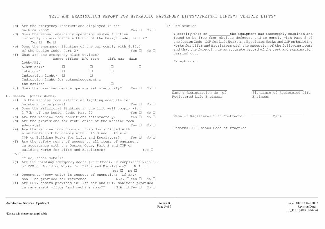
TEST AND EXAMINATION REPORT FOR HYDRAULIC PASSENGER LIFTS*/FREIGHT LIFTS*/ VEHICLE LIFTS*
Architectural Services Department
Annex B
Issue Date: 17 Dec 2007
Page 5 of 5 Revision Date: - LF_TCP (2007 Edition) *Delete whichever not applicable
(c) Are the emergency instructions displayed in the machine room? Yes No
(d) Does the manual emergency operation system function correctly in accordance with 8.9 of the Design code, Part 2?
Yes No (e) Does the emergency lighting of the car comply with 4.16.3
of the Design Code, Part 2? Yes No (f) What are the emergency alarm devices? Mangt office M/C room Lift car Main
lobby/Pit Alarm bell* Intercom* Indication light* Indication light for acknowledgement & the notice*
(g) Does the overload device operate satisfactorily? Yes No 13. General (Other Works) (a) Is the machine room artificial lighting adequate for
maintenance purposes? Yes No (b) Does the artificial lighting in the lift well comply with
1.7(b) of the Design Code, Part 2? Yes No (c) Are the machine room conditions satisfactory? Yes No (d) Are the provisions for ventilation of the machine room
adequate? Yes No (e) Are the machine room doors or trap doors fitted with
a suitable lock to comply with 3.15.3 and 3.15.4 of COP on Building Works for Lifts and Escalators? Yes No
(f) Are the safety means of access to all items of equipment in accordance with the Design Code, Part 2 and COP on Building Works for Lifts and Escalators? Yes No
If no, state details (g) Are the hoistway emergency doors (if fitted), in compliance with 3.2
of COP on Building Works for Lifts and Escalators? N.A. Yes No
(h) Documents (copy only) in respect of exemptions (if any) shall be provided for reference N.A. Yes No
(i) Are CCTV camera provided in lift car and CCTV monitors provided in management office *and machine room*? N.A. Yes No
14. Declaration I certify that on the equipment was thoroughly examined and
found to be free from obvious defects, and to comply with Part 2 of the Design Code, COP for Lift Works and Escalator Works and COP on Building Works for Lifts and Escalators with the exception of the following items and that the foregoing is an accurate record of the test and examination carried out.
Exceptions:
Name & Registration No. of Signature of Registered Lift Registered Lift Engineer Engineer
Name of Registered Lift Contractor Date Remarks: COP means Code of Practice
Annex C Test and Examination Report for Escalators/ Passenger Conveyors

TEST AND EXAMINATION REPORT FOR ESCALATORS/PASSENGER CONVEYORS
Architectural Services Department
Annex C
Issue Date: 17 Dec 2007
Page 1 of 3 Revision Date: - LF_TCP (2007 Edition) *Delete whichever not applicable
1. Description of Installation Location
Environment: Outdoor*/Indoor* Manufacturer Plant No.
Identification No. Model No.
Angle of Inclination degree Rated Speed m/s Vertical Rise m Capacity
Persons/Hour Step Width mm Step Depth mm No. of Exposed Steps between Combplates Step
Height mm Distance between Handrail Centrelines mm Horizontal Travel Distance of the Steps at the ends mm Contract Power Supply Volt Hz Phase Type of Balustrade: Opaque*/Tempered Glass*/Others* Machinery Location: Inside Truss*/Outside Truss* Is yellow band provided on side edges*/leading*/ trailing*edge? Yes No Is sump pump provided at upper*/lower*station? Yes No
Is remote monitoring facilities provided? Yes No
2. Static Examination (a) Are the combplates and terminal guides adjusted properly? Yes No (b) Has the brake(s) been examined and found to be in order? Yes No (c) Is an auxiliary brake provided? N.A. Yes No 3. Dynamic Tests (a) Has the operation brake been tested at no load*/full load*
up*/down* condition? Yes No AND The stopping distance is mm (b) Does the auxiliary brake operate properly? N.A. Yes No (c) Does the overspeed device operate properly? N.A. Yes
No 4. Driving Motor Current Tests Driving Motor Manufacturer Serial Number Voltage at Time of Test Rated Power Form of Overload Protection:
3-Phase circuit breaker Running Current(A)
Overloads in each phase Up Down
Others No Load
Separate supply for machine compartment/power socket? Yes No 5. Clearance (a) Is the clearance between consecutive steps not exceeding 6mm? Yes No (b) Is the clearance between step and adjacent skirting
not exceeding 4mm? Yes No (c) Is the total clearance between step and both skirting not exceeding 7mm? Yes No (d) Is the clearance between the upper surface of the step
and the root of the comb teeth not exceeding 4mm? Yes No
(e) Is the distance between the floor and the lower point of the handrail into the newel within the range of 0.1m to 0.25m? Yes No 6. Insulation Resistance to Earth Power System: MΩ Safety Circuit: MΩ 7. Earthing (a) Is all metalwork enclosing conductors bonded to earth?
Yes No (b) Is the maximum continuity resistance to earth less than
0.5Ω? Yes No
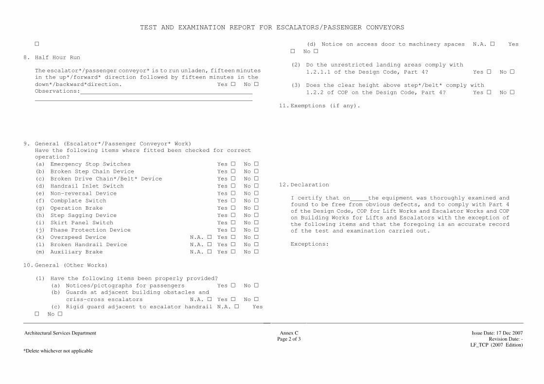
TEST AND EXAMINATION REPORT FOR ESCALATORS/PASSENGER CONVEYORS
Architectural Services Department
Annex C
Issue Date: 17 Dec 2007
Page 2 of 3 Revision Date: - LF_TCP (2007 Edition) *Delete whichever not applicable
8. Half Hour Run The escalator*/passenger conveyor* is to run unladen, fifteen minutes in the up*/forward* direction followed by fifteen minutes in the down*/backward*direction. Yes No Observations: 9. General (Escalator*/Passenger Conveyor* Work) Have the following items where fitted been checked for correct
operation? (a) Emergency Stop Switches Yes No
(b) Broken Step Chain Device Yes No (c) Broken Drive Chain*/Belt* Device Yes No
(d) Handrail Inlet Switch Yes No (e) Non-reversal Device Yes No
(f) Combplate Switch Yes No (g) Operation Brake Yes No
(h) Step Sagging Device Yes No (i) Skirt Panel Switch Yes No
(j) Phase Protection Device Yes No (k) Overspeed Device N.A. Yes No
(l) Broken Handrail Device N.A. Yes No (m) Auxiliary Brake N.A. Yes No 10. General (Other Works) (1) Have the following items been properly provided? (a) Notices/pictographs for passengers Yes No (b) Guards at adjacent building obstacles and criss-cross escalators N.A. Yes No (c) Rigid guard adjacent to escalator handrail N.A. Yes
No
(d) Notice on access door to machinery spaces N.A. Yes No
(2) Do the unrestricted landing areas comply with 1.2.1.1 of the Design Code, Part 4? Yes No
(3) Does the clear height above step*/belt* comply with 1.2.2 of COP on the Design Code, Part 4? Yes No 11. Exemptions (if any). 12. Declaration I certify that on the equipment was thoroughly examined and
found to be free from obvious defects, and to comply with Part 4 of the Design Code, COP for Lift Works and Escalator Works and COP on Building Works for Lifts and Escalators with the exception of the following items and that the foregoing is an accurate record of the test and examination carried out.
Exceptions:
TEST AND EXAMINATION REPORT FOR ESCALATORS/PASSENGER CONVEYORS
Arc
hite
ctur
al S
ervi
ces
Dep
artm
ent
A
nnex
C
Is
sue
Dat
e: 1
7 D
ec 2
007
Pa
ge 3
of 3
R
evis
ion
Dat
e: -
LF_T
CP
(200
7 E
ditio
n)
*Del
ete
whi
chev
er n
ot a
pplic
able
Name & Registration No. of
Signature of Registered
Escalator
Registered Escalator Engineer
Engineer
Name of Registered Escalator
Date
Contractor
Remarks: COP means Code of Practice
Annex D Test and Examination Report for Electric
Service Lifts
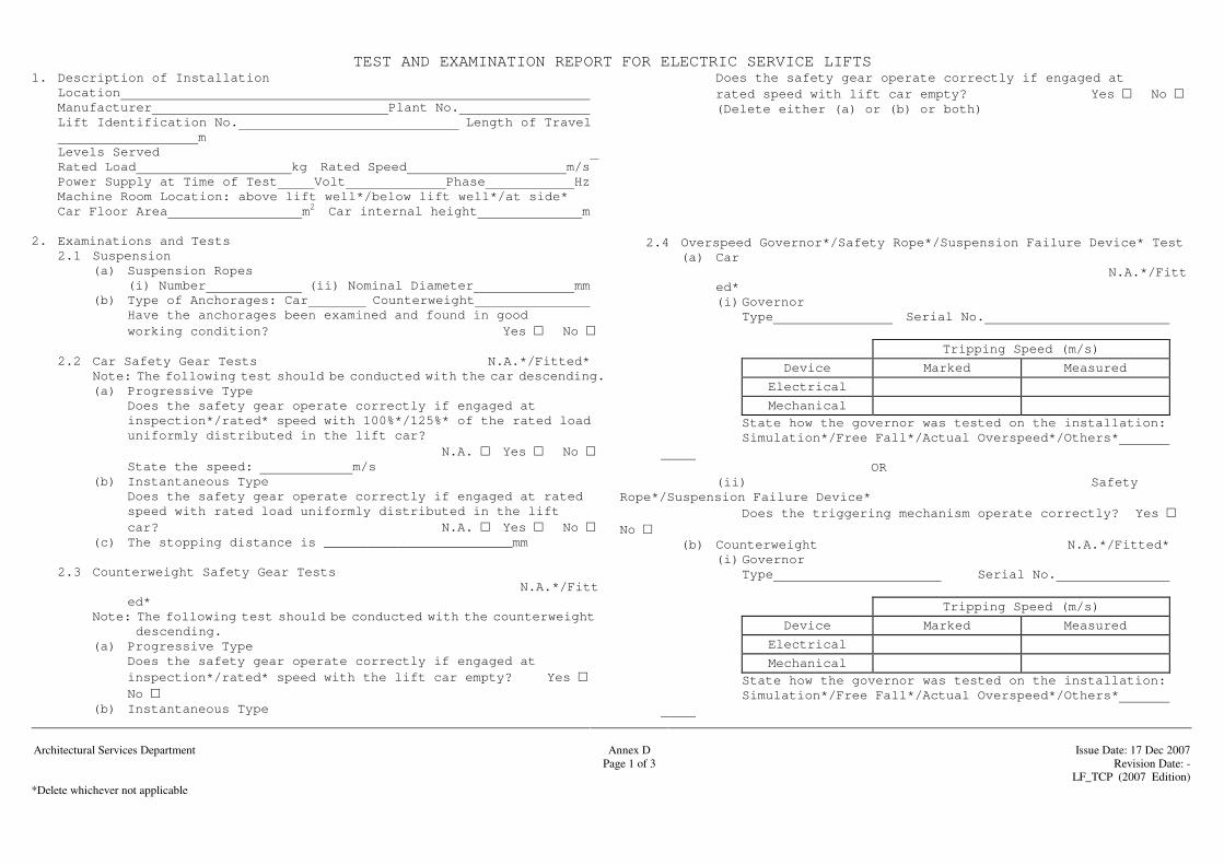
TEST AND EXAMINATION REPORT FOR ELECTRIC SERVICE LIFTS
Architectural Services Department
Annex D
Issue Date: 17 Dec 2007
Page 1 of 3 Revision Date: - LF_TCP (2007 Edition) *Delete whichever not applicable
1. Description of Installation Location Manufacturer Plant No. Lift Identification No. Length of Travel
m Levels Served Rated Load kg Rated Speed m/s Power Supply at Time of Test Volt Phase Hz Machine Room Location: above lift well*/below lift well*/at side* Car Floor Area m2 Car internal height m 2. Examinations and Tests 2.1 Suspension (a) Suspension Ropes (i) Number (ii) Nominal Diameter mm (b) Type of Anchorages: Car Counterweight Have the anchorages been examined and found in good working condition? Yes No 2.2 Car Safety Gear Tests N.A.*/Fitted*
Note: The following test should be conducted with the car descending. (a) Progressive Type Does the safety gear operate correctly if engaged at
inspection*/rated* speed with 100%*/125%* of the rated load uniformly distributed in the lift car?
N.A. Yes No State the speed: m/s (b) Instantaneous Type Does the safety gear operate correctly if engaged at rated
speed with rated load uniformly distributed in the lift car? N.A. Yes No
(c) The stopping distance is ________________________mm
2.3 Counterweight Safety Gear Tests N.A.*/Fitted*
Note: The following test should be conducted with the counterweight descending.
(a) Progressive Type Does the safety gear operate correctly if engaged at
inspection*/rated* speed with the lift car empty? Yes No
(b) Instantaneous Type
Does the safety gear operate correctly if engaged at rated speed with lift car empty? Yes No
(Delete either (a) or (b) or both) 2.4 Overspeed Governor*/Safety Rope*/Suspension Failure Device* Test
(a) Car N.A.*/Fitted* (i) Governor
Type Serial No.
Tripping Speed (m/s)
Device Marked Measured
Electrical
Mechanical
State how the governor was tested on the installation: Simulation*/Free Fall*/Actual Overspeed*/Others*
OR
(ii) Safety Rope*/Suspension Failure Device* Does the triggering mechanism operate correctly? Yes No (b) Counterweight N.A.*/Fitted* (i) Governor Type Serial No.
Tripping Speed (m/s)
Device Marked Measured
Electrical
Mechanical
State how the governor was tested on the installation: Simulation*/Free Fall*/Actual Overspeed*/Others*
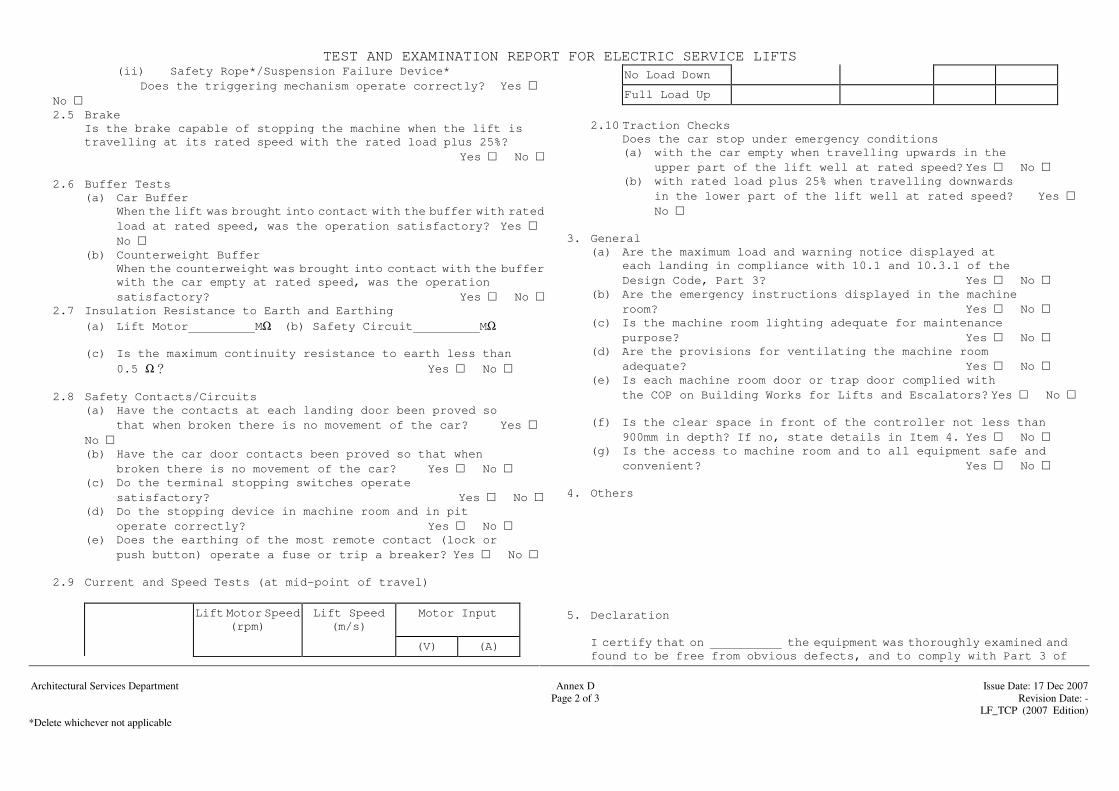
TEST AND EXAMINATION REPORT FOR ELECTRIC SERVICE LIFTS
Architectural Services Department
Annex D
Issue Date: 17 Dec 2007
Page 2 of 3 Revision Date: - LF_TCP (2007 Edition) *Delete whichever not applicable
(ii) Safety Rope*/Suspension Failure Device* Does the triggering mechanism operate correctly? Yes
No 2.5 Brake Is the brake capable of stopping the machine when the lift is
travelling at its rated speed with the rated load plus 25%? Yes No
2.6 Buffer Tests (a) Car Buffer When the lift was brought into contact with the buffer with rated
load at rated speed, was the operation satisfactory? Yes No
(b) Counterweight Buffer When the counterweight was brought into contact with the buffer
with the car empty at rated speed, was the operation satisfactory? Yes No 2.7 Insulation Resistance to Earth and Earthing (a) Lift Motor MΩ (b) Safety Circuit MΩ (c) Is the maximum continuity resistance to earth less than 0.5 Ω Yes No 2.8 Safety Contacts/Circuits (a) Have the contacts at each landing door been proved so
that when broken there is no movement of the car? Yes No
(b) Have the car door contacts been proved so that when broken there is no movement of the car? Yes No
(c) Do the terminal stopping switches operate satisfactory? Yes No
(d) Do the stopping device in machine room and in pit operate correctly? Yes No
(e) Does the earthing of the most remote contact (lock or push button) operate a fuse or trip a breaker? Yes No
2.9 Current and Speed Tests (at mid-point of travel)
Lift Motor Speed (rpm)
Lift Speed (m/s)
Motor Input
(V) (A)
No Load Down
Full Load Up
2.10 Traction Checks Does the car stop under emergency conditions (a) with the car empty when travelling upwards in the
upper part of the lift well at rated speed? Yes No (b) with rated load plus 25% when travelling downwards
in the lower part of the lift well at rated speed? Yes No
3. General
(a) Are the maximum load and warning notice displayed at each landing in compliance with 10.1 and 10.3.1 of the
Design Code, Part 3? Yes No (b) Are the emergency instructions displayed in the machine
room? Yes No (c) Is the machine room lighting adequate for maintenance purpose? Yes No (d) Are the provisions for ventilating the machine room adequate? Yes No (e) Is each machine room door or trap door complied with the COP on Building Works for Lifts and Escalators? Yes No (f) Is the clear space in front of the controller not less than 900mm in depth? If no, state details in Item 4. Yes No (g) Is the access to machine room and to all equipment safe and
convenient? Yes No
4. Others 5. Declaration I certify that on the equipment was thoroughly examined and
found to be free from obvious defects, and to comply with Part 3 of

TEST AND EXAMINATION REPORT FOR ELECTRIC SERVICE LIFTS
Architectural Services Department
Annex D
Issue Date: 17 Dec 2007
Page 3 of 3 Revision Date: - LF_TCP (2007 Edition) *Delete whichever not applicable
the Design Code, COP for Lift Works and Escalator Works and COP on Building Works for Lifts and Escalators with the exception of the following items and that the foregoing is an accurate record of the test and examination carried out.
Exceptions:
Name & Registration No. of Signature of Registered Lift Registered Lift Engineer Engineer
Name of Registered Lift Contractor Date Remarks: COP means Code of Practice


Annex E
Signature - Post :
Tel. No. :
Tested / Checked by : (Name of Contractor’s Representative)
( ) Date :
Signature - Post :
Tel. No. :
Witnessed by : (Name(s) of *PBSE/PBSI)
( ) Date : Architectural Services Department Annex E Issue Date: 17 Dec 2007 BSB– Standard Form No:PBS/SR.024(2007) Page 1 of 9 Revision Date: - LF_TCP (2007 Edition)
Testing and Commissioning Progress Chart “Lift Installation” Contract No. :
Contract Title :
Name of *Contractor / sub-contractor :
Contract Period : / /20 to / /20 * Revised/Actual Completion Date : / / 20
Testing and Commissioning Progress Chart for Lift Installation (Rev. )(1)
Dates (2) Remark Activities Reference to
Approved T&C Procedure
S A S A S A S A S A S A S A S A
1. Testing/checking of Landing Fixtures-including door, architrave, control and indicating devices
Section 3.1 to 3.3
G/F 1/F 2/F 3/F 4/F /F /F Submission of Record of Test
2.
Testing/checking of lift cars internal fittings – including car panel, floor, lighting, ventilation and control station
Section 3.1 to 3.3
Submission of Record of Test

Annex E
Testing and Commissioning Progress Chart “Lift Installation”
Testing and Commissioning Progress Chart for Lift Installation (Rev. )(1)
Dates (2) Remark
Activities Reference to Approved T&C
Procedure
S A S A S A S A S A S A S A S A
Signature - Post :
Tel. No. :
Tested / Checked by : (Name of Contractor’s Representative)
( ) Date :
Signature - Post :
Tel. No. :
Witnessed by : (Name(s) of *PBSE/PBSI)
( ) Date : Architectural Services Department Annex E Issue Date: 17 Dec 2007 BSB– Standard Form No:PBS/SR.024(2007) Page 2 of 9 Revision Date: - LF_TCP (2007 Edition)
3.
Testing/checking Installation within machine room - including governor, controller and lift machine/motor
Section 3.1 to 3.3
Submission of Record of Test
4.
Testing/checking Installation within lift shaft - including guide rail, drainage facilities, counter weight and buffer
Section 3.1 to 3.3
Submission of Record of Test
5. Testing/checking
hydraulic portion of work (for hydraulic lift installation only) -
Section 3.1 to 3.3
Submission of Record of Test
6. Testing/checking of
motor drive system Section 3.1 to 3.3
Submission of Record of Test
7. Testing/checking of
electrical system Section 3.1 to 3.3
Submission of Record of Test
8. Testing/checking of
control/safety system Section 3.1 to 3.3
Submission of Record of Test
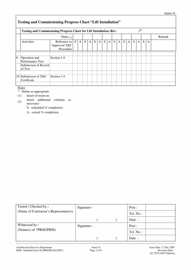
Annex E
Testing and Commissioning Progress Chart “Lift Installation”
Testing and Commissioning Progress Chart for Lift Installation (Rev. )(1)
Dates (2) Remark
Activities Reference to Approved T&C
Procedure
S A S A S A S A S A S A S A S A
Signature - Post :
Tel. No. :
Tested / Checked by : (Name of Contractor’s Representative)
( ) Date :
Signature - Post :
Tel. No. :
Witnessed by : (Name(s) of *PBSE/PBSI)
( ) Date : Architectural Services Department Annex E Issue Date: 17 Dec 2007 BSB– Standard Form No:PBS/SR.024(2007) Page 3 of 9 Revision Date: - LF_TCP (2007 Edition)
9. Operation and
Performance Test Section 3.4
Submission of Record of Test
10 Submission of T&C
Certificate Section 3.4
Notes * Delete as appropriate (1) Insert revision no.
(2) Insert additional columns as necessary
S - scheduled % completion A – actual % completion

Annex E
Signature - Post :
Tel. No. :
Tested / Checked by : (Name of Contractor’s Representative)
( ) Date :
Signature - Post :
Tel. No. :
Witnessed by : (Name(s) of *PBSE/PBSI)
( ) Date :
Architectural Services Department
Annex E
Issue Date: 17 Dec 2007
BSB– Standard Form No:PBS/SR.034(2007) Page 4 of 9 Revision Date: - LF_TCP (2007 Edition)
Testing and commissioning progress chart "Escalator/Passenger Conveyor Installation" Contract No. :
Contract Title :
Name of *Contractor / sub-contractor :
Contract Period : / /20 to / /20 * Revised/Actual Completion Date : / / 20
Testing and Commissioning Progress Chart for Escalator Installation (Rev. )(1)
Dates (2) Remark Activities Reference to
Approved T&C Procedure
S A S A S A S A S A S A S A S A
1. Testing/checking of steps and step chains
Section 3.1-3.3
Submission of Record of Test
2. Testing/checking
of hand rails Section 3.1-3.3
Submission of Record of Test
3. Testing/checking
of driving machineryt
Section 3.1-3.3
Submission of Record of Test
4. Testing/checking
of motor drive system
Section 3.1-3.3
Submission of Record of Test
5 Testing/checking
of electrical system
Section 3.1-3.3
Submission of Record of Test

Annex E
Testing and commissioning progress chart " Escalator Installation "
Testing and Commissioning Progress Chart for Escalator Installation (Rev. )(1)
Dates (2) Remark
Activities Reference to Approved T&C Procedure
S A S A S A S A S A S A S A S A
Signature - Post :
Tel. No. :
Tested / Checked by : (Name of Contractor’s Representative)
( ) Date :
Signature - Post :
Tel. No. :
Witnessed by : (Name(s) of *PBSE/PBSI)
( ) Date :
Architectural Services Department
Annex E
Issue Date: 17 Dec 2007
BSB– Standard Form No:PBS/SR.034(2007) Page 5 of 9 Revision Date: - LF_TCP (2007 Edition)
6 Testing/checking of control/safety system
Section 3.1-3.3
Submission of
Record of Test
7. Operation and
Performance Test
Section 3.4
Submission of Record of Test
8 Submission of
T&C Certificate Section 3.4
Notes * Delete as appropriate (1) Insert revision no. (2) Insert additional columns as necessary S - scheduled % completion A – actual % completion

Annex E
Signature - Post :
Tel. No. :
Tested / Checked by : (Name of Contractor’s Representative)
( ) Date :
Signature - Post :
Tel. No. :
Witnessed by : (Name(s) of *PBSE/PBSI)
( ) Date :
Architectural Services Department
Annex E
Issue Date: 17 Dec 2007
BSB– Standard Form No:PBS/SR.034(2007) Page 6 of 9 Revision Date: - LF_TCP (2007 Edition)
Testing and commissioning progress chart "Power Vertical Lifting Platform Installation" Contract No. :
Contract Title :
Name of *Contractor / sub-contractor :
Contract Period : / /20 to / /20 * Revised/Actual Completion Date : / / 20
Testing and Commissioning Progress Chart for Escalator Installation (Rev. )(1)
Dates (2) Remark Activities Reference to
Approved T&C Procedure
S A S A S A S A S A S A S A S A
1. Testing/checking of platform
Section 3.1-3.3
Submission of Record of Test
2. Testing/checking
of doors/gates Section 3.1-3.3
Submission of Record of Test
3. Testing/checking
of guide system Section 3.1-3.3
Submission of Record of Test
4. Testing/checking
of motor drive system
Section 3.1-3.3
Submission of Record of Test
5 Testing/checking
of electrical system
Section 3.1-3.3
Submission of Record of Test

Annex E
Testing and commissioning progress chart " Escalator Installation "
Testing and Commissioning Progress Chart for Escalator Installation (Rev. )(1)
Dates (2) Remark
Activities Reference to Approved T&C Procedure
S A S A S A S A S A S A S A S A
Signature - Post :
Tel. No. :
Tested / Checked by : (Name of Contractor’s Representative)
( ) Date :
Signature - Post :
Tel. No. :
Witnessed by : (Name(s) of *PBSE/PBSI)
( ) Date :
Architectural Services Department
Annex E
Issue Date: 17 Dec 2007
BSB– Standard Form No:PBS/SR.034(2007) Page 7 of 9 Revision Date: - LF_TCP (2007 Edition)
6 Testing/checking of control/safety system
Section 3.1-3.3
Submission of
Record of Test
7. Operation and
Performance Test
Section 3.4
Submission of Record of Test
8 Submission of
T&C Certificate Section 3.4
Notes * Delete as appropriate (1) Insert revision no. (2) Insert additional columns as necessary S - scheduled % completion A – actual % completion

Annex E
Signature - Post :
Tel. No. :
Tested / Checked by : (Name of Contractor’s Representative)
( ) Date :
Signature - Post :
Tel. No. :
Witnessed by : (Name(s) of *PBSE/PBSI)
( ) Date :
Architectural Services Department
Annex E
Issue Date: 17 Dec 2007
BSB– Standard Form No:PBS/SR.034(2007) Page 8 of 9 Revision Date: - LF_TCP (2007 Edition)
Testing and commissioning progress chart "Stairlift Installation" Contract No. :
Contract Title :
Name of *Contractor / sub-contractor :
Contract Period : / /20 to / /20 * Revised/Actual Completion Date : / / 20
Testing and Commissioning Progress Chart for Escalator Installation (Rev. )(1)
Dates (2) Remark Activities Reference to
Approved T&C Procedure
S A S A S A S A S A S A S A S A
1. Testing/checking of stairlift platform
Section 3.1-3.3
Submission of Record of Test
2. Testing/checking
of doors/gates Section 3.1-3.3
Submission of Record of Test
3. Testing/checking
of guide system Section 3.1-3.3
Submission of Record of Test
4. Testing/checking
of motor drive system
Section 3.1-3.3
Submission of Record of Test
5 Testing/checking
of electrical system
Section 3.1-3.3
Submission of Record of Test

Annex E
Testing and commissioning progress chart " Escalator Installation "
Testing and Commissioning Progress Chart for Escalator Installation (Rev. )(1)
Dates (2) Remark
Activities Reference to Approved T&C Procedure
S A S A S A S A S A S A S A S A
Signature - Post :
Tel. No. :
Tested / Checked by : (Name of Contractor’s Representative)
( ) Date :
Signature - Post :
Tel. No. :
Witnessed by : (Name(s) of *PBSE/PBSI)
( ) Date :
Architectural Services Department
Annex E
Issue Date: 17 Dec 2007
BSB– Standard Form No:PBS/SR.034(2007) Page 9 of 9 Revision Date: - LF_TCP (2007 Edition)
6 Testing/checking of control/safety system
Section 3.1-3.3
Submission of
Record of Test
7. Operation and
Performance Test
Section 3.4
Submission of Record of Test
8 Submission of
T&C Certificate Section 3.4
Notes * Delete as appropriate (1) Insert revision no. (2) Insert additional columns as necessary S - scheduled % completion A – actual % completion
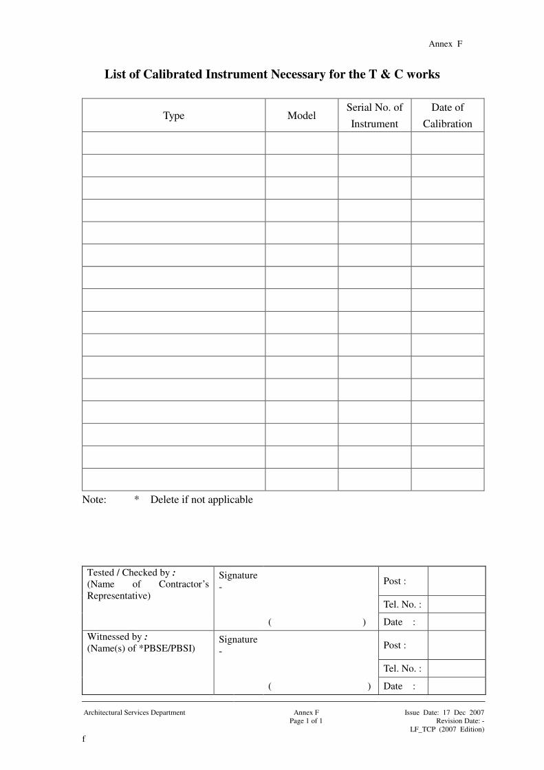
Annex F
Signature - Post :
Tel. No. :
Tested / Checked by : (Name of Contractor’s Representative)
( ) Date :
Signature - Post :
Tel. No. :
Witnessed by : (Name(s) of *PBSE/PBSI)
( ) Date : Architectural Services Department Annex F Issue Date: 17 Dec 2007 Page 1 of 1 Revision Date: - LF_TCP (2007 Edition) f
List of Calibrated Instrument Necessary for the T & C works
Type Model Serial No. of Instrument
Date of Calibration
Note: * Delete if not applicable
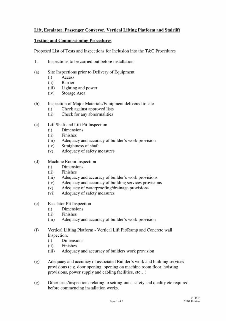
Page 1 of 3
LF_TCP 2007 Edition
Lift, Escalator, Passenger Conveyor, Vertical Lifting Platform and Stairlift Testing and Commissioning Procedures Proposed List of Tests and Inspections for Inclusion into the T&C Procedures 1. Inspections to be carried out before installation (a) Site Inspections prior to Delivery of Equipment
(i) Access (ii) Barrier (iii) Lighting and power (iv) Storage Area
(b) Inspection of Major Materials/Equipment delivered to site
(i) Check against approved lists (ii) Check for any abnormalities
(c) Lift Shaft and Lift Pit Inspection
(i) Dimensions (ii) Finishes (iii) Adequacy and accuracy of builder’s work provision (iv) Straightness of shaft (v) Adequacy of safety measures
(d) Machine Room Inspection
(i) Dimensions (ii) Finishes (iii) Adequacy and accuracy of builder’s work provisions (iv) Adequacy and accuracy of building services provisions (v) Adequacy of waterproofing/drainage provisions (vi) Adequacy of safety measures
(e) Escalator Pit Inspection
(i) Dimensions (ii) Finishes (iii) Adequacy and accuracy of builder’s work provision
(f) Vertical Lifting Platform - Vertical Lift Pit/Ramp and Concrete wall
Inspection: (i) Dimensions (ii) Finishes (iii) Adequacy and accuracy of builders work provision
(g) Adequacy and accuracy of associated Builder’s work and building services
provisions (e.g. door opening, opening on machine room floor, hoisting provisions, power supply and cabling facilities, etc…)
(g) Other tests/inspections relating to setting-outs, safety and quality etc required
before commencing installation works.
Page 2 of 3
LF_TCP 2007 Edition
2. Inspections to be carried out during installation
(i) Guide rails and fixing inside lift shaft (ii) Guide shoes (iii) Suspension rope termination including compensation chain/rope (iv) Traction machine (v) Overspeed governor (vi) Buffer (vii) Electrical installation in lift shaft (viii) Electrical installation in machine room (ix) Inspection required before energisation
3. Inspection and functional performance tests to be carried out upon completion A. Lifts
(i) Landing fixture (ii) Car door and landing doors (iii) Safety devices for doors (iv) Lift car (v) Control station in car (vi) Car door operation (vii) Safety gear and overspeed governor (viii) Ascending car protection means/speed reducing element (ix) Automatic control system (x) Installations inside machine room (xi) Motor (xii) Lift shaft and pit (xiii) Counterweight (xiv) Riding quality (xv) Hydraulic system (for hydraulic lift only)
B. Escalators
(i) Steps (ii) Combs (iii) Balustrades (iv) Handrails (v) Driving Machinery and Braking (vi) Machinery space (vii) Safety devices (viii) Control station (ix) Controller (x) Functional tests on automatic operations (for Service-on-demand only) (xi) Adequate provisions for weatherproof/outdoor escalator (xii) Miscellaneous items
Page 3 of 3
LF_TCP 2007 Edition
C. Vertical Lifting Platform
(i) Visual inspections on general provisions and miscellaneous items (ii) Safety devices (iii) Performance tests (iv) Adequate provisions for weatherproof/outdoor vertical lifting platform
D. Stairlifts
(i) Visual inspections on general provisions and miscellaneous items (ii) Safety devices (iii) Performance tests
4. Statutory Tests as stipulated in COPs