testing 5g new radio devices...with 5g new radio (nr) initial standards approved by 3gpp and first...
TRANSCRIPT

Testing 5G New Radio Devices
Master the complexities of 5G New Radio and accelerate your 5G designs

With 5G New Radio (NR) initial standards approved by 3GPP and first chipsets released, the race is on to design and deliver high quality devices that can meet the tough requirements of 5G. 5G NR uses new technologies and provides performance improvements due to flexible numerology, more complex waveforms and channel coding techniques, frequencies that extend into millimeter-wave (mmWave), wider channel bandwidths, and advanced multi-antenna access schemes. This combination of new technologies significantly increases complexity in design and test. This application brochure describes new test methodologies and techniques for testing 5G NR chipsets, components, and devices so you can accelerate your 5G NR designs.
5G NR Test Applications
• Testing 5G NR Data Throughput
• 5G NR OTA Beamforming Functional Test
• OTA Test for mmWave 5G NR Devices and Systems
Testing 5G NR Data Throughput
5G NR will require much faster data rates in order to support enhanced mobile
broadband (eMBB) use cases like UHD video streaming, virtual reality (VR), and
augmented reality (AR). As mobile operators accelerate their 5G NR deployment
plans, chipset and device manufacturers must also accelerate their development
activities, including determining how to test 5G NR data throughput most effectively.
The 5G eMBB (enhanced mobile broadband) use case targets data rates of up to
20 Gbps in the downlink (DL) and 10 Gbps in the uplink (UL). 5G NR accomplishes
this by utilizing higher-frequency mmWave spectrum, in addition to using sub-6 GHz
frequencies. LTE operates at frequencies up to 6 GHz, whereas mmWave operating
bands up to 52.6 GHz are already approved in 5G NR Release-15. 5G NR introduces
new frame structures and beamforming access procedures that increase design
complexity, increasing design difficulty and functional prototype test procedures.
Top challenges testing 5G NR device throughput include:• Configuring 5G NR frame structures for higher throughput
• Configuring 5G NR devices to make and report measurements for optimal
link adaptation
• Optimizing 5G NR beamforming performance at mmWave frequencies
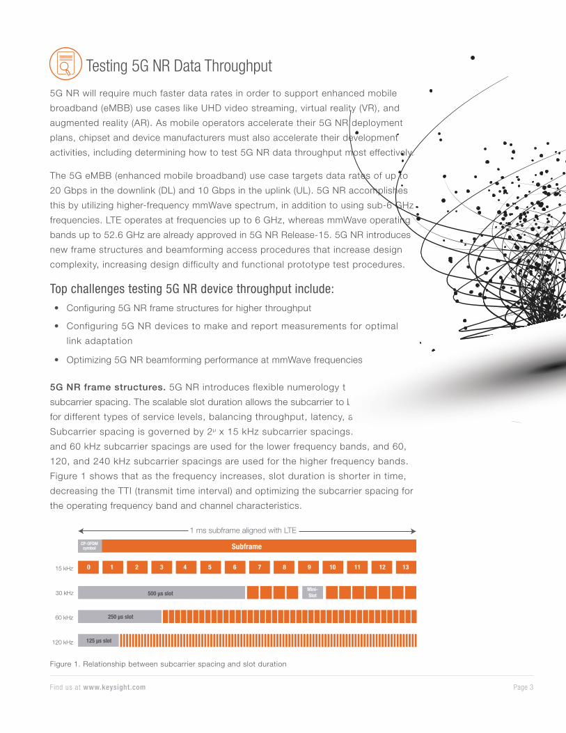
5G NR frame structures. 5G NR introduces flexible numerology that scales the
subcarrier spacing. The scalable slot duration allows the subcarrier to be optimized
for different types of service levels, balancing throughput, latency, and reliability.
Subcarrier spacing is governed by 2µ x 15 kHz subcarrier spacings. 15, 30,
and 60 kHz subcarrier spacings are used for the lower frequency bands, and 60,
120, and 240 kHz subcarrier spacings are used for the higher frequency bands.
Figure 1 shows that as the frequency increases, slot duration is shorter in time,
decreasing the TTI (transmit time interval) and optimizing the subcarrier spacing for
the operating frequency band and channel characteristics.
0 1 2 3 4 5 6 7 8 9 10 11 12 13
Mini-Slot
125 µs slot
500 µs slot
250 µs slot
120 kHz
60 kHz
30 kHz
15 kHz
SubframeCP-OFDM symbol
1 ms subframe aligned with LTE
Figure 1. Relationship between subcarrier spacing and slot duration
Page 3Find us at www.keysight.com

In TDD (time division duplex) bands, 5G NR also allows dynamic TDD operation
where the network can dynamically assign each slot to be DL or UL. This allows
more efficient use of the spectrum. By using dynamic TDD, the network can
allocate more or fewer resources for DL or UL, depending on the specific traffic
requirement of the network, device, and service being provided.
While testing 5G NR device throughput, it is critical to have access into the lower-
layer frame structure to configure and test for maximum throughput.
Beamforming performance at mmWave frequencies. Beamforming can be
used to overcome propagation and penetration losses at higher frequencies.
Beamforming achieves a stronger signal-to-noise ratio (SNR) by using high
directive radiation beams that provide additional antenna gain. The following new
procedures for beamforming have been defined in the 5G NR specifications:
• Beam acquisition and tracking
• Beam refinement
• Beam feedback
• Beam switching
1
2
3
4
5G LTE
TD-LTE HSPA+
WCDMA GSM
WiFi
1 2 3 4
Beam State Information
Beam index
BR
S R
ecei
ved
Pow
er
1 2 3 4
Beam State Information
Beam index
BR
S R
ecei
ved
Pow
er
Beam State Information (BSI) based on BRS
gNB5G UE
Candidate beam set(beams 1, 2, 3 and 4)
Figure 2. Analyzing 5G beam refinement
Many factors at different
layers of the protocol
stack impact beamforming
performance. Locating
bottlenecks and testing
different structures is vital
for optimizing throughput.
In addition, testing
beamforming at mmWave
frequencies requires over-
the-air (OTA) test methods
that further complicate the
test solution.
Page 4Find us at www.keysight.com
Since 5G NR implements new frame structures and beamforming techniques at
mmWave frequencies, having a test platform that enables evaluation and tuning at
different layers of the protocol stack can be very valuable. Keysight’s 5G Protocol R&D
Toolset provides an easy-to-use solution with the ability to monitor and make changes
at different layers of the protocol stack, providing insights for rapid optimization of
device throughput.
For more information see application note: Testing 5G Data Throughput
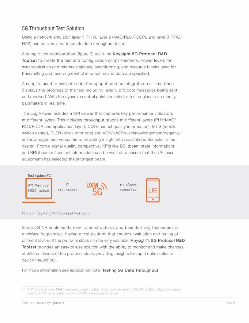
Figure 3. Keysight 5G throughput test setup
Page 5Find us at www.keysight.com
5G Throughput Test SolutionUsing a network emulator, layer 1 (PHY), layer 2 (MAC/RLC/PDCP), and layer 3 (RRC/
NAS) can be simulated to create data throughput tests.1
A sample test configuration (figure 3) uses the Keysight 5G Protocol R&D
Toolset to create the test and configuration script elements. Power levels for
synchronization and reference signals, beamforming, and resource blocks used for
transmitting and receiving control information and data are specified.
A script is used to evaluate data throughput, and an integrated real-time trace
displays the progress of the test including layer 3 protocol messages being sent
and received. With the dynamic control points enabled, a test engineer can modify
parameters in real time.
The Log Viewer includes a KPI viewer that captures key performance indicators
at different layers. This includes throughput graphs at different layers (PHY/MAC/
RLC/PDCP and application layer), CQI (channel quality information), MCS (mobile
switch center), BLER (block error rate) and ACK/NACKs (acknowledgement/negative
acknowledgement) versus time, providing insight into possible bottlenecks in the
design. From a signal quality perspective, KPIs like BSI (beam state information)
and BRI (beam refinement information) can be verified to ensure that the UE (user
equipment) has selected the strongest beam.
UXMUE
mmWaveconnection
IPconnection
5G ProtocolR&D Toolset
Test system PC
1 PHY: physical layer, MAC: medium access control, RLC: radio link control, PDCP: packet data convergence control, RRC: radio resource control, NAS: non-access stratum
5G NR OTA Beamforming Functional Test
3GPP 5G NR Release-15 specifies mobile operation up to 52.6 GHz. To overcome
higher path loss and multi-path propagation issues at these higher frequencies, beam
steering or beamforming will be used. Beam steering is not new and can provide
high directivity signals to a desired direction. However, beam steering for mobile
communications at mmWave frequencies requires new access techniques that need
to be tested and validated. Devices and base stations need to find each other and
maintain a quality communication link while the device moves through the network.
5G NR devices operating in the new frequency range 2 (FR2) mmWave operating
bands are likely to have their antennas integrated into the chipset and handsets
making it difficult to probe for conducted tests. Therefore, over-the-air (OTA) testing
is expected to replace traditional conducted test methods that were used in sub-
6 GHz designs. OTA testing can also provide a more realistic assessment of beam
performance in real-world scenarios.
Top challenges testing mmWave beamforming include:• Validating mmWave initial access
• Optimizing mmWave beam tracking and switching
• Testing beamforming over-the-air (OTA)
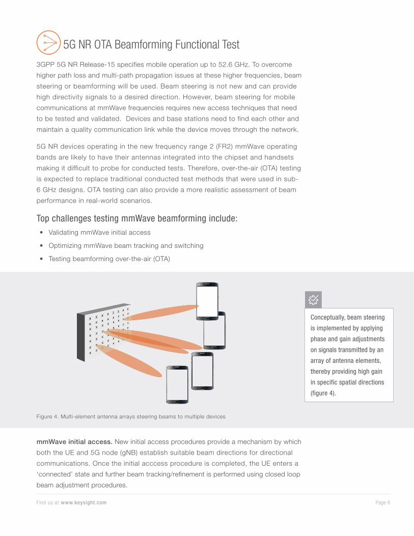
Figure 4. Multi-element antenna arrays steering beams to multiple devices
Conceptually, beam steering
is implemented by applying
phase and gain adjustments
on signals transmitted by an
array of antenna elements,
thereby providing high gain
in specific spatial directions
(figure 4).
mmWave initial access. New initial access procedures provide a mechanism by which
both the UE and 5G node (gNB) establish suitable beam directions for directional
communications. Once the initial acccess procedure is completed, the UE enters a
‘connected’ state and further beam tracking/refinement is performed using closed loop
beam adjustment procedures.
Page 6Find us at www.keysight.com
Beam refinement. Using the channel state reporting (CSI) reporting mechanism, the
5G node can track the state of downlink beams with periodic reference signal (CSI-
RS) measurements. If the serving beam is sub-optimal, the 5G node can instruct the
UE to switch to a different beam.
The highly directional nature of beamformed signals makes it critical to test initial
access, beam tracking, and beam switching procedures with beams coming from
different angular directions. This requires a real-time OTA test environment.
Solution for testing mmWave OTA beamforming
To support mmWave OTA beamforming measurements, the Keysight UXM 5G wireless
test platform can be used with mmWave RF heads and dual polarized horn antennas.
The UXM network emulator, together with mmW RF heads, acts as a gNB and supports
above-6 GHz transmitter (i.e., downlink) and receiver (i.e., uplink) RF ports. The
solution implements the baseband and protocol processing elements to emulate
the 5G network entities. This platform enables 5G NR protocol and RF tests. When
combined with mmWave RF heads, dual polarized horn antennas, and an anechoic
chamber, emulation of simultaneous downlink beams is possible. This setup can be
further enhanced, with the addition of positioners to control UE orientation. In this
configuration, 5G beamforming with angle of arrival (AoA) test capability in different
spatial orientations is possible.
Page 7Find us at www.keysight.com

The Keysight 5G Protocol R&D Toolset provides scripted control of 5G NR protocol
configuration parameters and procedures such that this OTA test setup can be
used to test UE beam power measurements, beam acquisition and tracking, beam
switching, and other mobility and protocol test scenarios.
For more information see application note: OTA Setup for 5G TF Beamforming
Functional Tests
mmWhead
mmWhead
mmWhead
mmWhead
mmWhead
mmWhead
mmWhead
mmWhead
Tx/Rx
Tx/Rx
Tx/Rx
Tx/Rx
Tx/Rx
Tx/Rx
Tx/Rx
Tx/Rx
NETWORK EMULATOR
HORN
HORN
HORN
HORN
HH
H H
HH
H H
VV
VV
VV
VV
HV
POLARIZATIONPOLARIZATION
Figure 5. Simulating downlink with multiple angle of arrivals
Page 8Find us at www.keysight.com
OTA Test for mmWave 5G NR Devices and Systems
mmWave frequencies are important in 5G because they offer more contiguous spectrum
and wider bandwidth radio channels. mmWave signals, however, are also subject to
signal propagation issues such as increased path loss, delay spread, or even blockage
due to chassis or human interference, all of which make it more difficult to establish
and maintain a mobile-to-base station wireless communication link. Over-the-air (OTA)
testing is needed to test modems that have integrated antennas. OTA tests will be used
to visualize, characterize, and validate 5G device beam patterns and performance in a
variety of real-world scenarios. OTA testing is one of the most challenging aspects of 5G
device development.
Top challenges testing mmWave beamforming include:• Issues testing mmWave devices in the far-field
• OTA test methodologies still being defined
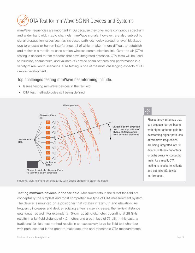
Figure 6. Multi-element antenna array with phase shifters to steer the beam
Phased array antennas that
can produce narrow beams
with higher antenna gain for
overcoming higher path loss
at mmWave frequencies,
are being integrated into 5G
devices with no connectors
or probe points for conducted
tests. As a result, OTA
testing is needed to validate
and optimize 5G device
performance.
Transmitter (TX)
Element controls phase shifters to vary the beam direction
Antenna array
Variable beam direction due to superposition of phase-shifted signals from antenna elements
Phase shifters (Φ)
Wave planes
�
�
�
�
�
�
�
�
Testing mmWave devices in the far-field. Measurements in the direct far-field are
conceptually the simplest and most comprehensive type of OTA measurement system.
The device is mounted on a positioner that rotates in azimuth and elevation. As
frequency increases and device-radiating antenna size increases, the far-field distance
gets longer as well. For example, a 15-cm radiating diameter, operating at 28 GHz,
results in a far-field distance of 4.2 meters and a path loss of 73 dB. In this case, a
traditional far-field test method results in an excessively large far-field test chamber
with path loss that is too great to make accurate and repeatable OTA measurements.
Page 9Find us at www.keysight.com

OTA test methodologies. OTA tests are required at different phases of the
development cycle, from R&D through conformance tests, and into manufacturing,
installation, and maintenance. OTA test solutions must be flexible to handle a wide
range of needs. Conformance testing is a critical milestone that all base stations and
UEs must pass before being released into the market. 3GPP conformance tests can be
grouped into RF, radio resource management (RRM), demodulation, and signaling tests.
To date, these tests are less than 50% defined, leaving a big gap in OTA test methods.
Due to the range of test requirements across the design and validation lifecycle, no
single test method can fully cover all possible test needs. Understanding the underlying
challenges and proposed OTA test methods will be essential to early success with 5G
NR device development.
OTA Test Solution
A typical OTA test solution will include an anechoic chamber, different probing
techniques, and test equipment to generate and analyze the radiated signals in a spatial
setting. The anechoic chamber provides a non-reflective environment with shielding
from outside interferences so that radiated signals of known power and direction can be
generated and measured in a controlled environment.
OTA test methodology can roughly be determined by the operation frequency, device
radiating antenna array dimension, and what tests need to be performed. To date,
3GPP has approved three RF performance OTA test methods for base stations and
UEs as shown in table 1.
Direct Far-Field (DFF) In-Direct Far-Field (IFF)Near-Field to Far-Field Transformation (NFTF)
A simple, comprehensive approach
Provides a near-field to far-field conversion enabled in a compact antenna test range
(CATR)
A compact approach that can be lower cost
Can be very large with greater path loss for
mmWave devices
Suitable for testing mmWave devices but not well suited for
spatial RRM test
Limited application for transceiver only, no receiver or
RF parametric tests yet
Table 1. A comparison of 3GPP approved OTA test methods
The DFF test method is the most capable and covers a broad spectrum of test needs.
However, due to the excessive path loss with larger radiating antenna arrays, the DFF
method can only be used with devices that have radiating antenna arrays ≤ 5 cm.
The IFF test method is a new alternative offering a far-field test environment in a much
shorter distance than the DFF method.
Page 10Find us at www.keysight.com
Page 11This information is subject to change without notice. © Keysight Technologies, 2018, Published in USA, October 31, 2018, 5992-3413EN
Find us at www.keysight.com
Learn more at: www.keysight.com
For more information on Keysight Technologies’ products, applications or services,
please contact your local Keysight office. The complete list is available at:
www.keysight.com/find/contactus
It can take a considerable amount of time and rework to investigate and implement an
OTA test solution on your own. Consider Keysight as an OTA partner wth experience
implementing the different OTA methods that can be used across different phases of
the device lifecycle. Keysight’s OTA test solutions include chambers, probing, and
the test equipment used to address a wide range of RF, demodulation, and functional
performance tests requirements from RF to mmWave frequencies.
For more information see white paper: OTA Test for Millimeter-Wave 5G NR Devices
and Systems
ConclusionNew 5G technologies and performance improvements are driving the need for new test
methodologies. As flexible numerology, more complex waveforms and channel coding
techniques, frequencies that extend into mmWave, wider channel bandwidths, and
advanced multi-antenna access schemes are implemented in 5G devices, designers
need to access multiple levels of the protocol stack to sufficiently test throughput and
beamforming performance. In addition, the need for OTA test solutions complicates the
situation even further.
Keysight partnered early with industry leaders to understand the complexities of
5G and to develop test solutions that span the entire workflow, from simulation and
development, to design verification, conformance and acceptance test, and ultimately
to manufacturing and deployment.
Our solutions leverage the same measurement techniques throughout the workflow
to ensure consistent results, guiding you to the appropriate test solutions specified
by chipset vendors and operators, enabling you to leverage measurements and get to
market faster.