test report - adafruit industries · pdf fileemc test report report no.: i15d00070-emc east...
TRANSCRIPT

TEST REPORT
No. I15D00070-EMC
For
Client: Shanghai SIMCom Wireless Solutions
Co.,Ltd.
Production: GSM/GPRS+GPS Module
Model Name: SIM808
Hardware Version: V2.01
Software Version: SIM800 R14.18
Issued date: 2015-06-26
Note:
The test results in this test report relate only to the devices specified in this report. This report shall not
be reproduced except in full without the written approval of ECIT Shanghai.
Test Laboratory:
ECIT Shanghai, East China Institute of Telecommunications
Add: 7-8F, G Area, No.668, Beijing East Road, Huangpu District, Shanghai, P. R. China
Tel: (+86)-021-63843300, E-Mail: [email protected]

EMC Test Report Report No.: I15D00070-EMC
East China Institute of Telecommunications Page Number : 2 of 30 TEL: +86 21 63843300FAX:+86 21 63843301 Report Issued Date : Jun. 26,2015
Revision Version
Report Number Revision Date Memo
I15D00070-EMC 00 2015-06-26 Initial creation of test report

EMC Test Report Report No.: I15D00070-EMC
East China Institute of Telecommunications Page Number : 3 of 30 TEL: +86 21 63843300FAX:+86 21 63843301 Report Issued Date : Jun. 26,2015
CONTENTS
1. TEST LABORATORY ............................................................................................................................ 5
1.1. TESTING LOCATION ............................................................................................................................ 5
1.2. TESTING ENVIRONMENT .................................................................................................................... 5
1.3. PROJECT DATA .................................................................................................................................... 5
1.4. SIGNATURE .......................................................................................................................................... 5
2. CLIENT INFORMATION ........................................................................................................................ 6
2.1. APPLICANT INFORMATION ................................................................................................................ 6
2.2. MANUFACTURER INFORMATION ...................................................................................................... 6
3. EQUIPMENT UNDER TEST (EUT) AND ANCILLARY EQUIPMENT (AE) ......................................... 7
3.1. ABOUT EUT .......................................................................................................................................... 7
3.2. INTERNAL IDENTIFICATION OF EUT USED DURING THE TEST .................................................... 7
3.3. INTERNAL IDENTIFICATION OF AE USED DURING THE TEST ...................................................... 7
4. REFERENCE DOCUMENTS ................................................................................................................ 8
4.1. REFERENCE DOCUMENTS FOR TESTING ....................................................................................... 8
4.2. GENERAL PERFORMANCE DESCRIPTION FOR EN 55024 ............................................................ 9
4.2.1GENERAL DESCRIPTION ..................................................................................................................... 9
4.2.2.GENERAL PERFORMANCE CRITERIA DESCRIPTION ................................................................... 10
5. TEST RESULTS .................................................................................................................................. 11
5.1. SUMMARY OF TEST RESULTS ......................................................................................................... 11
5.2. STATEMENTS ..................................................................................................................................... 11
6. TEST METHODOLOGY ...................................................................................................................... 12
6.1. DECISION OF FINAL TEST MODE .................................................................................................... 12
6.2. EUT SYSTEM OPERATION ................................................................................................................ 12
7. TEST EQUIPMENTS UTILIZED .......................................................................................................... 13
8. MEASUREMENT RESULTS ............................................................................................................... 15

EMC Test Report Report No.: I15D00070-EMC
East China Institute of Telecommunications Page Number : 4 of 30 TEL: +86 21 63843300FAX:+86 21 63843301 Report Issued Date : Jun. 26,2015
8.1. RADIATED EMISSION ........................................................................................................................ 15
8.2. ELECTROSTATIC DISCHARGE......................................................................................................... 18
8.3. RF ELECTROMAGNETIC FIELD ....................................................................................................... 20
ANNEX A TEST CONFIGURATION PHOTOS ............................................................................................. 25
ANNEX B EUT PHOTOS .............................................................................................................................. 27

EMC Test Report Report No.: I15D00070-EMC
East China Institute of Telecommunications Page Number : 5 of 30 TEL: +86 21 63843300FAX:+86 21 63843301 Report Issued Date : Jun. 26,2015
1. Test Laboratory
1.1. Testing Location
Company Name: ECIT Shanghai, East China Institute of Telecommunications
Address: 7-8F, G Area,No. 668, Beijing East Road, Huangpu District, Shanghai, P. R.
China
Postal Code: 200001
Telephone: (+86)-021-63843300
Fax: (+86)-021-63843301
1.2. Testing Environment
NormalTemperature: 15-35℃
Relative Humidity: 30-60%
1.3. Project data
Project Leader: Chen Kan
Testing Start Date: 2015-06-01
Testing End Date: 2015-06-26
1.4. Signature

EMC Test Report Report No.: I15D00070-EMC
East China Institute of Telecommunications Page Number : 6 of 30 TEL: +86 21 63843300FAX:+86 21 63843301 Report Issued Date : Jun. 26,2015
2. Client Information
2.1. Applicant Information
Company Name: Shanghai SIMCom Wireless Solutions Co.,Ltd.
Address: Building A,SIM Technology Building,No.633,Jinzhong Road,Changning
District,Shanghai R.R.China
Telephone: 86-021-32523300
Postcode: 200335
2.2. Manufacturer Information
Company Name: Shenyang Simcom Technology Ltd.
Address: No.37, Shenbei Rd, Shenbei New Aear, Shenyang,P.R.China
Telephone: 86-024-88922222
Postcode: N/A

EMC Test Report Report No.: I15D00070-EMC
East China Institute of Telecommunications Page Number : 7 of 30 TEL: +86 21 63843300FAX:+86 21 63843301 Report Issued Date : Jun. 26,2015
3. Equipment under Test (EUT) and Ancillary Equipment (AE)
3.1. About EUT
ProductName GSM/GPRS+GPS Module
Model name SIM808
GSM Frequency Band GSM900/GSM1800/GSM850/GSM1900
Additional Communication Function GPS/2G AGPS
Note: Photographs of EUT are shown in ANNEX B of this test report.
3.2. Internal Identification of EUT used during the test
EUT ID* SN or IMEI HW Version SW Version Date of receipt
N01 865067020388784 V2.01 SIM800 R14.18 2015-05-25
*EUT ID: is used to identify the test sample in the lab internally.
3.3. Internal Identification of AE used during the test
AE ID* Description Model SN
AE1 GPS Antenna / /
AE2 Earphone / /
AE3 USB cable / /
AE4 Notebook ThinkPad Edge E430 /
*AE ID: is used to identify the test sample in the lab internally.

EMC Test Report Report No.: I15D00070-EMC
East China Institute of Telecommunications Page Number : 8 of 30 TEL: +86 21 63843300FAX:+86 21 63843301 Report Issued Date : Jun. 26,2015
4. Reference Documents
4.1. Reference Documents for testing
The following documents listed in this section are referred for testing.
Reference Title Version
ETSI EN
301489-1 Part 1: Common technical requirements V1.9.2(2011-09)
ETSI EN
301489-3
Part 3: Specific conditions for Short-Range Devices (SRD)
operating on frequencies between 9 kHz and 40 GHz V1.6.1(2013-08)
ETSI EN
301489-7
Part 7: Specific conditions for mobile and portable radio and
ancillary equipment of digital cellular radio telecommunications
systems (GSM and DCS)
V1.3.1(2005-11)
EN
55022:(2010)
Information technology equipment –-- Radio disturbance
characteristics---- Limits and methods of measurement 2010-12
EN
55024:(2010)
Information technology equipment –-- Immunity characteristics----
Limits and methods of measurement 2010-11

EMC Test Report Report No.: I15D00070-EMC
East China Institute of Telecommunications Page Number : 9 of 30 TEL: +86 21 63843300FAX:+86 21 63843301 Report Issued Date : Jun. 26,2015
4.2. GENERAL PERFORMANCE DESCRIPTION for EN 55024
4.2.1GENERAL DESCRIPTION
Product Standard EN 55024: 2010
Test Type Minimum Requirements
Basic Standard, Specification,
and Performance Criterion required
EN 61000-4-2 Electrostatic Discharge – ESD: 8KV air discharge, 4KV Contact discharge, Performance Criterion B
EN 61000-4-3 Radio-Frequency Electromagnetic Field Susceptibility Test – RS: 80 ~1000 MHz, 3V/m, 80% AM(1KHz), Performance Criterion A
EN 61000-4-4 Electrical Fast Transient/Burst - EFT, AC PowerPort: 1KV DC PowerPort: 0.5KV SignalPorts and TelecommunicationPorts: 0.5KV Performance Criterion B
EN 61000-4-5 Surge Immunity Test: For Power: 1.2/50 μs Open Circuit Voltage, 8/20 μs Short Circuit Current, AC Power Port ~ line to line: 1KV, line to earth (ground): 2KV DC Power Port ~ line to earth: 0.5KV Performance Criterion B
For SignalPorts and TelecommunicationPorts: 10/700μs generator: With primary protectors fitted:4KV Without primary protectors:1KV Performance Criterion C
EN 61000-4-6 Conducted Radio Frequency Disturbances Test –CS: 0.15 ~ 80 MHz, 3Vrms, 80% AM, 1KHz, Performance Criterion A
EN 61000-4-11 Voltage Dips:AC 50Hz
i) >95% reduction for 0.5 period, Performance Criterion B
ii) 30% reduction for 25 period, Performance Criterion C
Voltage Interruptions:
>95% reduction for 250 period
Performance Criterion C

EMC Test Report Report No.: I15D00070-EMC
East China Institute of Telecommunications Page Number : 10 of 30 TEL: +86 21 63843300FAX:+86 21 63843301 Report Issued Date : Jun. 26,2015
4.2.2.GENERAL PERFORMANCE CRITERIA DESCRIPTION
Criteria A:
The apparatus shell continues to operate as intended without operator intervention. No degradation of performance or loss of function is allowed below a performance level specified by the manufacturer, when the apparatus is used as intended. The performance level may be replaced by a permissible loss of performance. If the manufacturer does not specify the minimum performance level or the permissible performance loss, then either of these may be derived from the product description and documentation, and by what the user may reasonably expect from the equipment if used as intended.
Criteria B:
After test, the apparatus shell continues to operate as intended without operator intervention. No degradation of performance or loss of function is allowed, after the application of the phenomenon below a performance level specified by the manufacturer, when the apparatus is used as intended. The performance level may be replaced by a permissible loss of performance.
During the test, degradation of performance is however allowed. However, no change of operating state if stored data is allowed to persist after the test. If the manufacturer does not specify the minimum performance level or the permissible performance loss, then either of these may be derived from the product description and documentation, and by what the user may reasonably expect from the equipment if used as intended.
Criteria C:
Temporary loss of function is allowed, provided the functions is self-recoverable or can be restored by the operation of controls by the user in accordance with the manufacturer instructions.
Functions, and/or information stored in non-volatile memory, or protected by a battery backup, shall not be lost.

EMC Test Report Report No.: I15D00070-EMC
East China Institute of Telecommunications Page Number : 11 of 30 TEL: +86 21 63843300FAX:+86 21 63843301 Report Issued Date : Jun. 26,2015
5. Test Results
5.1. Summary of Test Results
Note: NA means not applicable.
Items Test List Standard Verdict
1 Radiated Emission EN55022 (2010) Pass
2 Conducted Emission EN55022 (2010) NA
3 Harmonic Current Emissions EN61000-3-2
(2006+A1:2009+A2:2009) NA
4 Voltage Fluctuations and Flicker EN61000-3-3 (2008) NA
5 Electrostatic Discharge EN 61000-4-2(2009) Pass
6 RF Electromagnetic Field EN 61000-4-3
(2006+A1:2008+A2:2010) Pass
7 Fast Transients Common Mode EN 61000-4-4 (2004+A1:2010) NA
8 Surge EN 61000-4-5 (2006) NA
9 RF Common Mode EN 61000-4-6 (2009) NA
10 Voltage Dips and Interruptions EN 61000-4-11 (2004) NA
5.2. Statements
The SIM808, supporting GSM manufactured by Shenyang Simcom Technology Ltd. is a new product for
testing. ECIT only performed test cases which identified with Pass/Fail/Inc result in section 5.1.
ECIT has verified that the compliance of the tested device specified in section 3 of this test report is
successfully evaluated according to the procedure and test methods as defined in type certification
requirement listed in section 4 of this test report.
EMC Test Report Report No.: I15D00070-EMC
East China Institute of Telecommunications Page Number : 12 of 30 TEL: +86 21 63843300FAX:+86 21 63843301 Report Issued Date : Jun. 26,2015
6. TEST METHODOLOGY
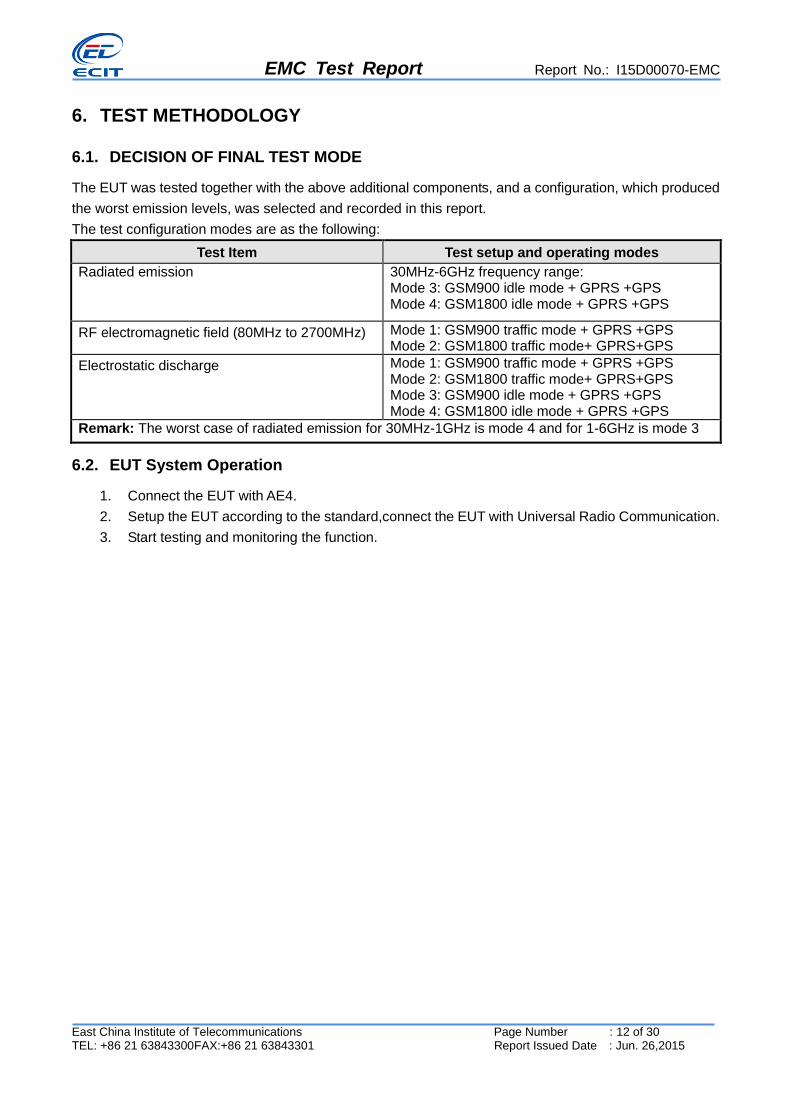
6.1. DECISION OF FINAL TEST MODE
The EUT was tested together with the above additional components, and a configuration, which produced
the worst emission levels, was selected and recorded in this report.
The test configuration modes are as the following:
Test Item Test setup and operating modes
Radiated emission 30MHz-6GHz frequency range: Mode 3: GSM900 idle mode + GPRS +GPS Mode 4: GSM1800 idle mode + GPRS +GPS
RF electromagnetic field (80MHz to 2700MHz) Mode 1: GSM900 traffic mode + GPRS +GPS Mode 2: GSM1800 traffic mode+ GPRS+GPS
Electrostatic discharge Mode 1: GSM900 traffic mode + GPRS +GPS Mode 2: GSM1800 traffic mode+ GPRS+GPS Mode 3: GSM900 idle mode + GPRS +GPS Mode 4: GSM1800 idle mode + GPRS +GPS
Remark: The worst case of radiated emission for 30MHz-1GHz is mode 4 and for 1-6GHz is mode 3
6.2. EUT System Operation
1. Connect the EUT with AE4.
2. Setup the EUT according to the standard,connect the EUT with Universal Radio Communication.
3. Start testing and monitoring the function.

EMC Test Report Report No.: I15D00070-EMC
East China Institute of Telecommunications Page Number : 13 of 30 TEL: +86 21 63843300FAX:+86 21 63843301 Report Issued Date : Jun. 26,2015
7. Test Equipments Utilized
No
. Name Type Series Number Producer Cal.Date
Cal.int
erval
1 Universal Radio
Communication
Tester
CMU200 123102 R&S 2014-07-07 1
2 Test Receiver ESCI 101235 R&S 2014-07-06 1
3 Test Receiver ESU40 100307 R&S 2014-07-25 1
4 Trilog Antenna VULB9163 VULB9163-515 Schwarzbeck 2014-11-05 3
5 Double Ridged
Guide
Antenna
ETS-3117 00135885 ETS 2014-05-06 3
6 2-Line
V-Network ENV216 101380 R&S 2014-07-25 1
7 Single Phase
Harmonic
&Flicker
DPA500N V1126109988 EM Test 2014-07-25 1
8 Multifunction
AC/DC Power
Source
Netwave7 V1126109989 EM Test 2014-07-25 1
9 Ultra Compact
Simulator UCS 500N7 V1126109983 EM Test 2014-07-22 1
10 Motorized
Variac MV 2616 V1126109987 EM Test 2014-07-22 1
11 Telecom Surge
Module TSurge7 V0902104582 EM Test 2014-07-22 1
12 Audio Analyzer UPV 101950 R&S 2014-07-07 1
13 Power Meter NRP2 101804 R&S 2014-07-07 1
14 Signal
Generator SMB 100A 105563 R&S 2014-07-07 1
15 Power Amplifier BLWA
0810-160/100D 118564A R&S N.C.R NA
16 Power Amplifier BLWA
1060-100/50D 118564B R&S N.C.R NA
17 Power Sensor NRP-Z51 102840 R&S 2014.07.07 1
18 Power Sensor NRP-Z51 102841 R&S 2014.07.07 1
19 ESD Test
Simulator Dito V1126109982 EM Test 2014-07-28 1
20 Signal
Generator SMB 100A 105562 R&S 2014-07-07 1

EMC Test Report Report No.: I15D00070-EMC
East China Institute of Telecommunications Page Number : 14 of 30 TEL: +86 21 63843300FAX:+86 21 63843301 Report Issued Date : Jun. 26,2015
21 Power Meter NRP2 101805 R&S 2014-07-07 1
22 Power Amplifier BBA100 100994 R&S N.C.R NA
23 Power Sensor NRP-Z91 101503 R&S 2014.07.07 1
24 Power Sensor NRP-Z91 101504 R&S 2014.07.07 1
25 CDN FCC-801-M2/M
3-16A 111779 FCC FISCHER 2014-07-25 1
26 EMI Test
Software EMC32 V9.15 NA R&S NA NA
27 EFT/SURGE/DI
P Test Software
iec . control
V5.1.7.0 NA EM TEST NA NA
28 Universal Radio
Communication CMW500 144668 R&S 2015-01-21 1

EMC Test Report Report No.: I15D00070-EMC
East China Institute of Telecommunications Page Number : 15 of 30 TEL: +86 21 63843300FAX:+86 21 63843301 Report Issued Date : Jun. 26,2015
8. Measurement Results
8.1. Radiated Emission
Method of Measurement
a. For 30-1000MHz, the EUT was placed on the top of a rotating 0.8-m table above the ground at a
semi-anechoic chamber. The distance between the EUT and the received antenna was 3 meters.
The table was rotated 360 degree andthe received antenna mounted on a variable-height antenna
tower was varied from 1m to 4m to find the maximum value of the field strength. Both horizontal and
vertical polarizations of the antenna were set during the measurement.
b. For 1000-6000MHz, the EUT was placed on the top of a 1.50m table above the ground at a 3m fully
anechoic chamber. The Received antenna was also fixed on the 1.50m height of the tower, 3m away
from the EUT. The table was rotated 360 degree to determine the maximum value of the field
strength. Both horizontal and vertical polarizations of the antenna were set during the measurement.
Limits for Radiated Emission at a measuring distance of 3m
Table 1:
Frequency Range (MHz) Quasi-Peak (dBV/m)
30-230 40
230-1000 47
Table 2:
Frequency Range (MHz) Peak (dBV/m) Average (dBV/m)
1000-3000 70 50
3000-6000 74 54
Table 3:
Test conditions
Frequency Range (MHz) RBW/VBW Sweep Time (s)
30-1000 120KHz/300KHz AUTO
1000-6000 1MHz/1MHz AUTO
Uncertainty Measurement
The measurement uncertainty is 5.59dB (k=2).

EMC Test Report Report No.: I15D00070-EMC
East China Institute of Telecommunications Page Number : 16 of 30 TEL: +86 21 63843300FAX:+86 21 63843301 Report Issued Date : Jun. 26,2015
Test Results
0
1 0
2 0
3 0
4 0
5 0
6 0
7 0
8 0
3 0 M 5 0 6 0 8 0 1 0 0 M 2 0 0 3 0 0 4 0 0 5 0 0 8 0 0 1 G
Le
vel i
n d
B礦
/m
F re q u e n c y in H z
E N 3 0 1 4 8 9 -1 R E 3 m Q P _ 3 0 M -1 G
Mode 4 (30M-1GHz)
Final Result 1
Frequency
(MHz)
QuasiPeak
(dBV/m)
Limit
(dBV /m)
Margin
(dB)
Meas.
Time
(ms)
Bandwidth
(kHz)
Height
(cm)
Pol Azimuth
(deg)
Corr.
(dB)
50.491667 27.43 40.00 12.57 1000.0 120.000 100.0 V 106.0 -25.1
96.097000 25.43 40.00 14.57 1000.0 120.000 100.0 V 43.0 -24.7
170.497667 31.69 40.00 8.31 1000.0 120.000 200.0 H 0.0 -26.1
231.299667 33.48 47.00 13.52 1000.0 120.000 200.0 H 203.0 -23.2
480.015333 35.92 47.00 11.08 1000.0 120.000 100.0 V 156.0 -15.5
941.436667 34.51 47.00 12.49 1000.0 120.000 100.0 V 202.0 -7.7
EMC Test Report Report No.: I15D00070-EMC
East China Institute of Telecommunications Page Number : 17 of 30 TEL: +86 21 63843300FAX:+86 21 63843301 Report Issued Date : Jun. 26,2015
0
1 0
2 0
3 0
4 0
5 0
6 0
7 0
8 0
1 G 2 G 3 G 4 G 5 G 6 G
Le
vel i
n d
B礦
/m
F re q u e n c y in H z
E N 3 0 1 4 8 9 -1 R E 3 m P K _ 1 G -6 G
E N 3 0 1 4 8 9 -1 R E 3 m A V _ 1 G -6 G
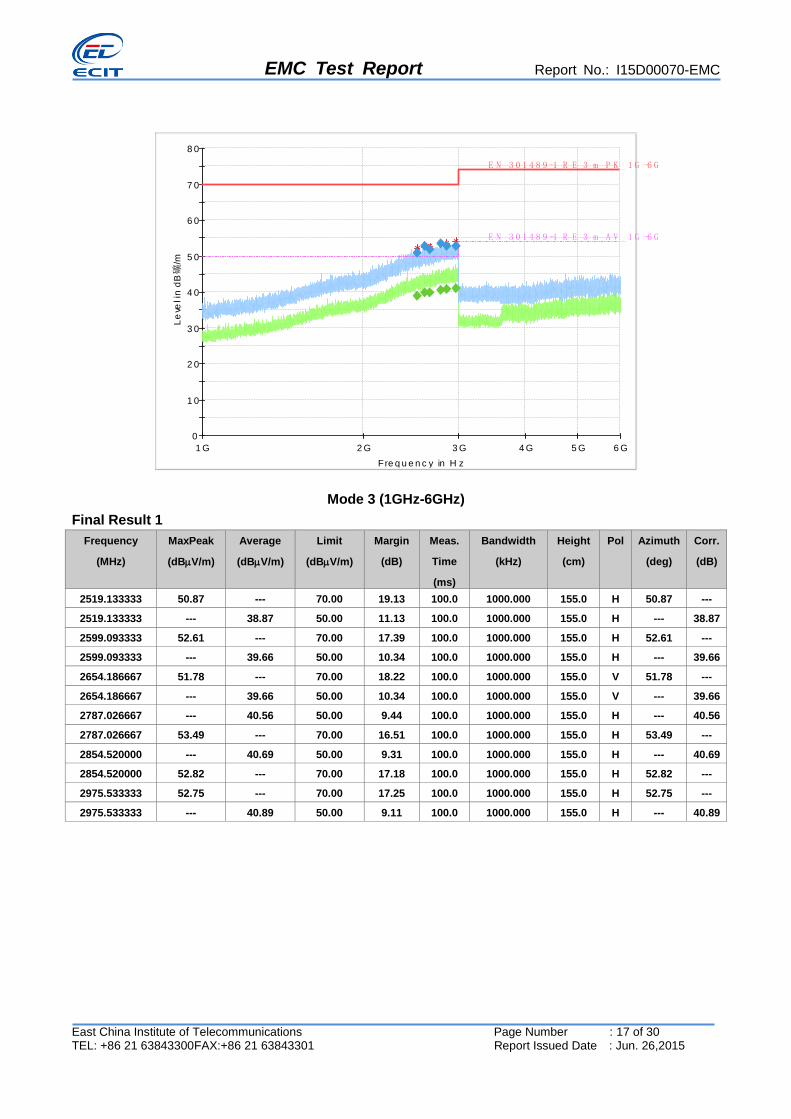
Mode 3 (1GHz-6GHz)
Final Result 1
Frequency
(MHz)
MaxPeak
(dBV/m)
Average
(dBV/m)
Limit
(dBV/m)
Margin
(dB)
Meas.
Time
(ms)
Bandwidth
(kHz)
Height
(cm)
Pol Azimuth
(deg)
Corr.
(dB)
2519.133333 50.87 --- 70.00 19.13 100.0 1000.000 155.0 H 50.87 ---
2519.133333 --- 38.87 50.00 11.13 100.0 1000.000 155.0 H --- 38.87
2599.093333 52.61 --- 70.00 17.39 100.0 1000.000 155.0 H 52.61 ---
2599.093333 --- 39.66 50.00 10.34 100.0 1000.000 155.0 H --- 39.66
2654.186667 51.78 --- 70.00 18.22 100.0 1000.000 155.0 V 51.78 ---
2654.186667 --- 39.66 50.00 10.34 100.0 1000.000 155.0 V --- 39.66
2787.026667 --- 40.56 50.00 9.44 100.0 1000.000 155.0 H --- 40.56
2787.026667 53.49 --- 70.00 16.51 100.0 1000.000 155.0 H 53.49 ---
2854.520000 --- 40.69 50.00 9.31 100.0 1000.000 155.0 H --- 40.69
2854.520000 52.82 --- 70.00 17.18 100.0 1000.000 155.0 H 52.82 ---
2975.533333 52.75 --- 70.00 17.25 100.0 1000.000 155.0 H 52.75 ---
2975.533333 --- 40.89 50.00 9.11 100.0 1000.000 155.0 H --- 40.89

EMC Test Report Report No.: I15D00070-EMC
East China Institute of Telecommunications Page Number : 18 of 30 TEL: +86 21 63843300FAX:+86 21 63843301 Report Issued Date : Jun. 26,2015
8.2. Electrostatic Discharge
Test Specification
Discharge Impedance: 330 ohm / 150pF
Discharge Voltage: Contact discharge (±4KV)
Polarity: Positive & Negative
Discharge Mode: Single Discharge
Discharge Period: 1 second minimum
Reference standard:
EN 301 489-1 V1.9.2 (2011-09)
EN 301 489-3 V1.6.1 (2013-08)
EN 301 489-7 V1.3.1(2005-11)
EN 55024:(2010)
Method of Measurement
The discharges shall be applied in two ways:
a. Contact discharges to the conductive surfaces and coupling planes
A method of testing, in which the electrode of the test generator is held in contact with the EUT, and
the discharge actuated by the discharge switch within the generator. Test shall be performed at a
maximum repetition rate of one discharge per second.
b. Air discharges at slots and apertures and insulating surfaces
On those parts of the EUT where it is not possible to perform contact discharge testing, the equipment
should be investigated to identify user accessible points where breakdown may occur. Such points
are tested using the air discharge method. This investigation should be restricted to those area
normally handled by the user. A minimum of 10 single air discharges shall be applied to the selected
test point for each such area.
Performance Criteria:
Performance criteria for Transient phenomena applied to Transmitters (TT)
Performance criteria for Transient phenomena applied to Receivers (TR)
A communications link shall be established at the start of the test.
At the conclusion of each exposure the EUT shall operate with no user noticeable loss of the
communication link.
At the conclusion of the total test comprising the series of individual exposures, the EUT shall
operate as intended with no loss of user control functions or stored data, as declared by the
manufacturer, and the communication link shall have been maintained.
In addition to confirming the above performance during a call, the test shall also be performed in
idle mode, and the transmitter shall not unintentionally operate.
Test Points
1. HCP 2. VCP
Test Results

EMC Test Report Report No.: I15D00070-EMC
East China Institute of Telecommunications Page Number : 19 of 30 TEL: +86 21 63843300FAX:+86 21 63843301 Report Issued Date : Jun. 26,2015
Test Points Test Level
(KV)
Contact or Air Application
Quantity
Result
1 ±4 Contact(indirect
discharge)
100 Pass
2 ±4 Contact(indirect
discharge)
100 Pass
EMC Test Report Report No.: I15D00070-EMC
East China Institute of Telecommunications Page Number : 20 of 30 TEL: +86 21 63843300FAX:+86 21 63843301 Report Issued Date : Jun. 26,2015
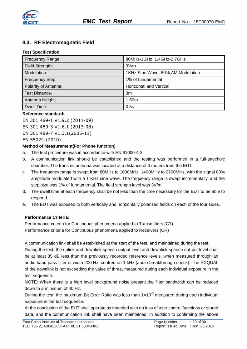
8.3. RF Electromagnetic Field
Test Specification
Frequency Range: 80MHz-1GHz ,1.4GHz-2.7GHz
Field Strength: 3V/m
Modulation: 1KHz Sine Wave, 80%,AM Modulation
Frequency Step: 1% of fundamental
Polarity of Antenna: Horizontal and Vertical
Test Distance: 3m
Antenna Height: 1.50m
Dwell Time: 0.5s
Reference standard:
EN 301 489-1 V1.9.2 (2011-09)
EN 301 489-3 V1.6.1 (2013-08)
EN 301 489-7 V1.3.1(2005-11)
EN 55024:(2010)
Method of Measurement(For Phone function)
a. The test procedure was in accordance with EN 61000-4-3.
b. A communication link should be established and the testing was performed in a full-anechoic
chamber. The transmit antenna was located at a distance of 3 meters from the EUT.
c. The frequency range is swept from 80MHz to 1000MHz, 1400MHz to 2700MHz, with the signal 80%
amplitude modulated with a 1 KHz sine wave. The frequency range is swept incrementally, and the
step size was 1% of fundamental. The field strength level was 3V/m.
d. The dwell time at each frequency shall be not less than the time necessary for the EUT to be able to
respond.
e. The EUT was exposed to both vertically and horizontally polarized fields on each of the four sides.
Performance Criteria:
Performance criteria for Continuous phenomena applied to Transmitters (CT)
Performance criteria for Continuous phenomena applied to Receivers (CR)
A communication link shall be established at the start of the test, and maintained during the test.
During the test, the uplink and downlink speech output level and downlink speech out put level shall
be at least 35 dB less than the previously recorded reference levels, when measured through an
audio band pass filter of width 200 Hz, centred on 1 kHz (audio breakthrough check). The RXQUAL
of the downlink is not exceeding the value of three, measured during each individual exposure in the
test sequence.
NOTE: When there is a high level background noise present the filter bandwidth can be reduced
down to a minimum of 40 Hz.
During the test, the maximum Bit Error Ratio was less than 1×10⁻³
measured during each individual
exposure in the test sequence.
At the conclusion of the EUT shall operate as intended with no loss of user control functions or stored
data, and the communication link shall have been maintained. In addition to confirming the above

EMC Test Report Report No.: I15D00070-EMC
East China Institute of Telecommunications Page Number : 21 of 30 TEL: +86 21 63843300FAX:+86 21 63843301 Report Issued Date : Jun. 26,2015
performance during a call, the test shall also be performed in idle mode, and the transmitter shall not
unintentionally operate.
Test Specification (For ITE function)
The test procedure was in accordance with EN 61000-4-3
a) The testing was performed in a fully anechoic chamber. The EUT and load, which are placed on a table
that is 0.8 meter above ground, are placed with one coincident with the calibration plane such that the
distance from antenna to the EUT was 3 meters.
b) All the scanning conditions are as follows:
Condition of Test Remarks
1. Field Strength 3 V/m
2. Radiated Signal AM80% Modulated with 1kHz
3. Scanning Frequency 80MHz - 1000MHz
4 Dwell Time 3 Seconds
5. Frequency step size △f: 1%
c) The dwell time at each frequency shall be not less than the time necessary for the EUT to be able to respond.
d) The test was performed with the EUT exposed to both vertically and horizontally polarized fields on each of the four sides.
e) In order to judge the EUT performance, a CCD camera is used to monitor EUT screen.
Test Conditions
Frequency
(MHz) EUT state Polarity
Field Strength
(V/m) Result Comments
80M-1GHz,
1.4-2.7GHz Front side H/V 3 Pass None
80M-1GHz,
1.4-2.7GHz Back side H/V 3 Pass None
80M-1GHz,
1.4-2.7GHz Left side H/V 3 Pass None
80M-1GHz,
1.4-2.7GHz Right side H/V 3 Pass None
Test Results
The worst case for RF electromagnetic field (80M-1G, 1.4-2.7G) is mode 2, and only the test data of this
mode was reported.

EMC Test Report Report No.: I15D00070-EMC
East China Institute of Telecommunications Page Number : 22 of 30 TEL: +86 21 63843300FAX:+86 21 63843301 Report Issued Date : Jun. 26,2015
-9 0
-8 0
-7 0
-6 0
-5 0
-4 0
-3 0
-2 0
-1 0
0
1 0
8 0 M 1 0 0 M 2 0 0 3 0 0 4 0 0 5 0 0 8 0 0 1 G 2 G 2 .7 G
AB
T_U
L in
dB
Pa
F re q u e n c y in H z
N o g o L im itlin e
2 .7 0 0 0 0 0 0 0 0 G H z-6 3 .0 0 1 d B P a
ABT_Uplink in dBPa (80M-1G, 1.4-2.7G, Horizontal)
-9 0
-8 0
-7 0
-6 0
-5 0
-4 0
-3 0
-2 0
-1 0
0
1 0
8 0 M 1 0 0 M 2 0 0 3 0 0 4 0 0 5 0 0 8 0 0 1 G 2 G 2 .7 G
AB
T_
DL
in
dB
Pa
Fre q u e n c y in H z
N o g o L im itlin e
2 .7 0 0 0 0 0 0 0 0 G H z-3 9 .1 0 2 d B P a
ABT_Downlink in dBPa (80M-1G, 1.4-2.7G, Horizontal)

EMC Test Report Report No.: I15D00070-EMC
East China Institute of Telecommunications Page Number : 23 of 30 TEL: +86 21 63843300FAX:+86 21 63843301 Report Issued Date : Jun. 26,2015
0
1
2
3
4
5
6
7
8
9
1 0
8 0 M 1 0 0 M 2 0 0 3 0 0 4 0 0 5 0 0 8 0 0 1 G 2 G 2 .7 G
Rx
Qu
al
Fre q u e n c y in H z
N o g o L im itlin e
2 .7 0 0 0 0 0 0 0 0 G H z0 .0 0 0
RX Quality (80M-1G, 1.4-2.7G, Horizontal)
-9 0
-8 0
-7 0
-6 0
-5 0
-4 0
-3 0
-2 0
-1 0
0
1 0
8 0 M 1 0 0 M 2 0 0 3 0 0 4 0 0 5 0 0 8 0 0 1 G 2 G 2 .7 G
AB
T_U
L in
dB
Pa
F re q u e n c y in H z
N o g o L im itlin e
2 .7 0 0 0 0 0 0 0 0 G H z-6 4 .2 5 8 d B P a
ABT_Uplink in dBPa (80M-1G, 1.4-2.7G, Vertical)

EMC Test Report Report No.: I15D00070-EMC
East China Institute of Telecommunications Page Number : 24 of 30 TEL: +86 21 63843300FAX:+86 21 63843301 Report Issued Date : Jun. 26,2015
-9 0
-8 0
-7 0
-6 0
-5 0
-4 0
-3 0
-2 0
-1 0
0
1 0
8 0 M 1 0 0 M 2 0 0 3 0 0 4 0 0 5 0 0 8 0 0 1 G 2 G 2 .7 G
AB
T_D
L in
dB
Pa
F re q u e n c y in H z
N o g o L im itlin e
2 .7 0 0 0 0 0 0 0 0 G H z-3 8 .9 1 5 d B P a
ABT_Downlink in dBPa (80M-1G, 1.4-2.7G, Vertical)
0
1
2
3
4
5
6
7
8
9
1 0
8 0 M 1 0 0 M 2 0 0 3 0 0 4 0 0 5 0 0 8 0 0 1 G 2 G 2 .7 G
Rx
Qu
al
F re q u e n c y in H z
N o g o L im itlin e
2 .7 0 0 0 0 0 0 0 0 G H z0 .0 0 0
RX Quality (80M-1G, 1.4-2.7G, Vertical)

EMC Test Report Report No.: I15D00070-EMC
East China Institute of Telecommunications Page Number : 25 of 30 TEL: +86 21 63843300FAX:+86 21 63843301 Report Issued Date : Jun. 26,2015
Annex A Test Configuration Photos
Picture1 : Photo of RE test
Picture2 : Photo of ESD test

EMC Test Report Report No.: I15D00070-EMC
East China Institute of Telecommunications Page Number : 26 of 30 TEL: +86 21 63843300FAX:+86 21 63843301 Report Issued Date : Jun. 26,2015
Picture3 : Photo of RS test

EMC Test Report Report No.: I15D00070-EMC
East China Institute of Telecommunications Page Number : 27 of 30 TEL: +86 21 63843300FAX:+86 21 63843301 Report Issued Date : Jun. 26,2015
Annex B EUT Photos
Picture1 : EUT + test AE
Picture2 : EUT + test AE

EMC Test Report Report No.: I15D00070-EMC
East China Institute of Telecommunications Page Number : 28 of 30 TEL: +86 21 63843300FAX:+86 21 63843301 Report Issued Date : Jun. 26,2015
Picture3 : EUT
Picture4 : EUT

EMC Test Report Report No.: I15D00070-EMC
East China Institute of Telecommunications Page Number : 29 of 30 TEL: +86 21 63843300FAX:+86 21 63843301 Report Issued Date : Jun. 26,2015
Picture5 : Photo of GPS Antenna
Picture6 : Photo of main antenna
EMC Test Report Report No.: I15D00070-EMC
East China Institute of Telecommunications Page Number : 30 of 30 TEL: +86 21 63843300FAX:+86 21 63843301 Report Issued Date : Jun. 26,2015
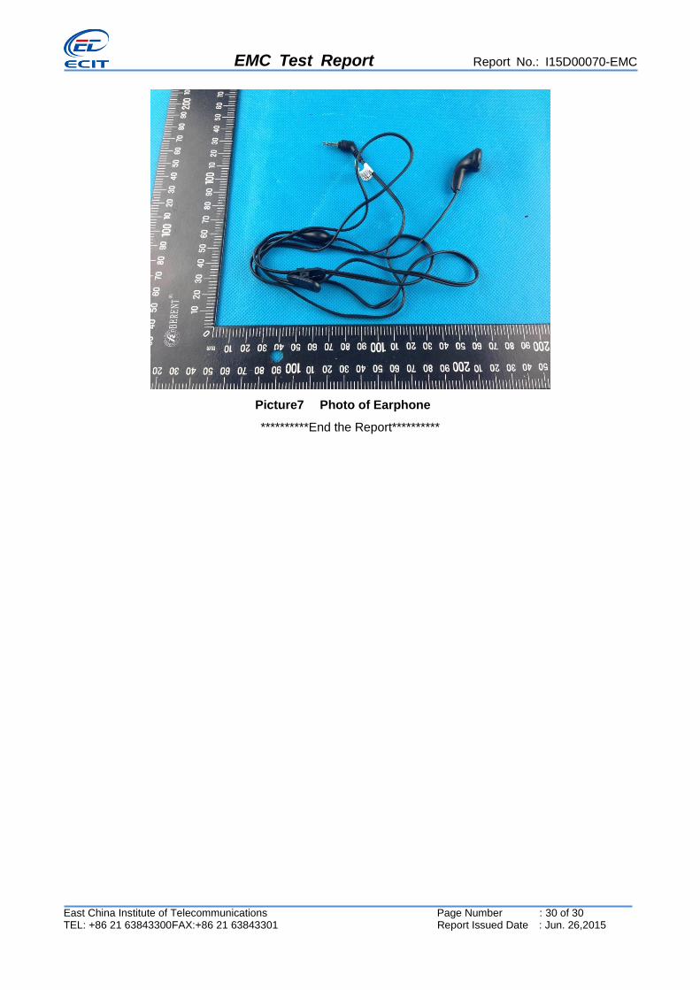
Picture7 Photo of Earphone
**********End the Report**********