fd30 test report & certificates - egger€¦ · fd30 test report & certificates global...
TRANSCRIPT
www.egger.co.uk
FD30 test report & certiFicates
Global assessment, acoustic RepoRt & DuRability RepoRt

Global Assessment of:
EGGER (UK) Limited
EGGER FD30 & FD30 Decor 44mm Door Blanks
For:
30 Minutes Fire Resistance
Report No: Chilt/A13085
Valid From: 29th April 2013
Valid Until: 29th April 2018
This document is confidential and remains the property of Chiltern International Fire Ltd. The legal validity of this report can only be claimed on the presentation of the complete report.
Prepared for: Egger (UK) Ltd. Anick Grange Road Hexham Northumberland NE46 4JS

The legal validity of this report can only be claimed on presentation of the complete report.
Report for: Egger (UK) Ltd. Ref: Chilt/A13085 Page 2 of 37
Contents
Page
No.
1 Introduction ................................................................................................................. 3
2 General Description of Construction ........................................................................... 3
3 Leaf Sizes................................................................................................................... 3
4 Configurations ............................................................................................................ 3
5 Leaf Size Adjustment .................................................................................................. 3
6 Edging Materials ......................................................................................................... 4
7 Door Frames .............................................................................................................. 5
8 Intumescent Materials ................................................................................................ 7
9 Overpanels ................................................................................................................. 8
10 Glazing ..................................................................................................................... 10
11 Leaf Facing Materials ............................................................................................... 11
12 Adhesives ................................................................................................................. 12
13 Tested Hardware ...................................................................................................... 12
14 Additional & Alternative Hardware ............................................................................ 13
15 Door Gaps ................................................................................................................ 16
16 Classification of Timber ............................................................................................ 16
17 Fixings ...................................................................................................................... 17
18 Sealing to Structural Opening ................................................................................... 17
19 Insulation .................................................................................................................. 18
20 Smoke Control .......................................................................................................... 19
21 Conclusion................................................................................................................ 19
22 Declaration by the Applicant ..................................................................................... 20
23 Limitations ................................................................................................................ 21
24 Validity ...................................................................................................................... 21
Appendix A > Performance Data ...................................................................................... 22
Appendix B > Proprietary 30 Minute Glazing Systems ..................................................... 22
Appendix C > Revisions ................................................................................................... 25
Appendix D > Data Sheets ............................................................................................... 26
The legal validity of this report can only be claimed on presentation of the complete report.
Report for: Egger (UK) Ltd. Ref: Chilt/A13085 Page 3 of 37
1 Introduction
This document constitutes a global assessment relating to Egger (UK) Ltd. 44mm thick, 30 minute fire resisting doorsets. The assessment uses established extrapolation and interpretation techniques in order to extend the scope of application by determining the limits for the design based on the tested constructions and performances obtained. The assessment is an evaluation of the potential fire resistance performance, if the elements were to be tested in accordance with BS 476: Part 22: 1987.
2 General Description of Construction
The primary construction for door leaves of this design comprises the following:
• A solid sheet of 44mm thick Egger particleboard (minimum density 540kg/m3 to maximum density 580kg/m3). Where required, the leaves are to be lipped.
3 Leaf Sizes
Assessment for increased leaf dimensions is based on the design’s performance and the characteristics exhibited during test. Data sheets specifying the maximum assessed leaf sizes and graphs showing the permitted gradient between maximum height and width are contained in appendix D.
Unequal leaf double doorsets are covered by this assessment with no restriction on the smaller leaf.
4 Configurations
Based on the test evidence listed in appendix A, this assessment covers the following doorset configurations:
Abbreviation Description
LSASD & ULSASD Latched & unlatched, single acting, single doorset
DASD Double acting, single doorset
LSASD+OP+ULSASD+OP Latched & unlatched, single acting, single doorset with overpanel
LSADD+ULSADD Latched & unlatched, single acting, double doorset
LSADD+OP+ULSADD+OP Latched & unlatched, single acting, double doorset with overpanel
DADD Double acting, double doorset
5 Leaf Size Adjustment
Egger particleboard core door leaves may be altered as follows:
Element Reduction
Leaf The manufactured size of the leaf may be reduced in height or width without restriction
Timber lippings
Dimensions stated in section 6.1 may be reduced by 20% for fitting purposes

The legal validity of this report can only be claimed on presentation of the complete report.
Report for: Egger (UK) Ltd. Ref: Chilt/A13085 Page 4 of 37
6 Edging Materials
6.1 Timber Lippings
Egger particleboard core door leaves must be lipped in accordance with the following specification:
Material Size (mm) Min. Density
(kg/m³)
Straight grained, joinery quality hardwood, free from knots, splits and
checks
1. Flat = 6A13 thick with a maximum 2mm profiling permitted at corners of lipping (see section 7.1)
640 2. Rounded = 10A15 thick with a radius matching the distance between the leaf edge and floor pivot (see section 7.1)
3. Rebated = 23A28 thick with a 15 high x 22 deep rebate
Notes:
• Single doorsets are not permitted with rebated vertical edges.
• Single & double doorsets without flush overpanels only require lipping on the vertical edges, but may be lipped on all edges if required.
• Doorsets with flush overpanels must be lipped on the vertical edges and additionally at the bottom edge of the overpanel and top edge of the doors.
• Single and double doorsets without flush overpanels must use square edges only.
• Double doorsets with flush overpanels may use a square or rebated overpanel junction.
• Double doorsets are not permitted with rebated meeting edges.
6.2 ABS Lippings
Single leaf Egger particleboard doors may be lipped in accordance with the following specification:
Material Size (mm) Density (kg/m3)
ABS 2 thick 1150A1160
Notes:
1. ABS lippings may be applied to all edges of single leaf doorsets only (see appendix D for leaf size ranges).
2. Where ABS lippings are fitted to single leaf doors, door edge intumescent seals must be fitted in the frame reveal, not the leaf edge.

The legal validity of this report can only be claimed on presentation of the complete report.
Report for: Egger (UK) Ltd. Ref: Chilt/A13085 Page 5 of 37
7 Door Frames
7.1 Door Frame Construction
Door frames for Egger particleboard core door leaves may be timber or MDF as follows:
Material Frame Section Size (mm) Min. Density
(kg/m³) Single Acting Double Acting
Softwood 70 x 32 70 x 40 510
Hardwood 70 x 32 70 x 40 510
MDF 70 x 30 70 x 40 750
If the doorset features a transomed overpanel, the door frame must be softwood or hardwood with a minimum section of 70mm x 32mm and of the minimum densities stated above. All door frame timber must be to class J30 as specified in BS EN 942: 2007 (see section 16).
Flush overpanels are not permitted with double acting doorsets.
A 12mm deep planted stop is adequate for single acting frames whilst double acting frames may be scalloped or square. If frames are square the maximum radius to the corners of the leaf is 8mm. Frame joints must be mortice and tenoned, mitred, half lapped, nailed or screwed and with no gaps.
The following diagram depicts the assessed frame profiles and dimensions:
Standard Scalloped Profiled edges
A = 70mm B = 30A40mm (see table above for details) C = 12mm
R = Radius from floor spring – 8mm radius to create maximum 2mm edge profiling

The legal validity of this report can only be claimed on presentation of the complete report.
Report for: Egger (UK) Ltd. Ref: Chilt/A13085 Page 6 of 37
7.2 Door Frame Installation
The following diagrams indicate acceptable door frame installations:
6 to 1 0 m m
M a x 10 x 1 0 m m sh a d ow g ap w ith 2 m m
in tu m e s ce n t m a s tic ca p p ing o r
10 x 4 m m P V C e n ca se d in tum e sce n t se a l
15 m m
P e rm itte d P e rm itte d
P e rm itte dN o t P e rm itte dN o t P e rm itte d
P e rm itte d
Note: See section 18 for sealing to structural opening requirements.
7.3 Door Frame Joints
Half Lapped Joint Mitre Joint
Mortice and Tenon Joint Butt Joint Note: Drawing is representative of each type of door frame joint; actual construction in terms of intumescent seal location and material, etc. must be as the text within this document specifies.

The legal validity of this report can only be claimed on presentation of the complete report.
Report for: Egger (UK) Ltd. Ref: Chilt/A13085 Page 7 of 37
8 Intumescent Materials
It is important that the type, size and fitting detail for the intumescent seals remains as tested. These products can often exhibit significantly different characteristics, which could alter the performances obtained during test, and therefore they must not be considered interchangeable, irrespective of whether the product has been tested and the seal dimensions are maintained.
The seal specification for each configuration is shown in appendix D.
The intumescent materials tested/assessed for this doorset design are as follows:
Application Location Product/Manufacturer
Edge seals Fitted in the frame jambs or leaf edges
1. Type 617 A Lorient Polyproducts Ltd. 2. 100P A Mann McGowan Fabrication Ltd. 3. Pyroplex Rigid Box Seal – Pyroplex Ltd.
Hinges
Under hinge blades
(doorsets over 2440)
1. 1mm MAP paper A Lorient Polyproducts Ltd. 2. 1mm Interdens A Dufaylite Developments Ltd. 3. 1mm ThermAAAFlex A Intumescent seals Ltd. 4. 1mm Pyrostrip A Mann McGowan Ltd.
Lock/latches
Under forend & keep
(forends over 57 x 26)
1. 1mm MAP paper A Lorient Polyproducts Ltd. 2. 1mm Interdens A Dufaylite Developments Ltd. 3. 1mm ThermAAAFlex A Intumescent seals Ltd. 4. 1mm Pyrostrip A Mann McGowan Ltd.
Flush bolts Lining all
sides of the mortices
1. 1mm MAP paper A Lorient Polyproducts Ltd. 2. 1mm Interdens A Dufaylite Developments Ltd. 3. 1mm ThermAAAFlex A Intumescent seals Ltd. 4. 1mm Pyrostrip A Mann McGowan Ltd.
Cableways Lining the
base of the groove
1. 1mm MAP paper A Lorient Polyproducts Ltd. 2. 1mm Interdens A Dufaylite Developments Ltd. 3. 1mm ThermAAAFlex A Intumescent seals Ltd. 4. 1mm Pyrostrip A Mann McGowan Ltd.
Top and bottom pivot
points
Lining all sides of the mortice
1. Interdens – Dufaylite Developments Ltd. 2. MAP paper A Lorient Polyproducts Ltd. 3. Approved intumescent protection pack as
supplied by hardware manufacturer
Note: See section 6.2 for intumescent seal location when ABS lippings are fitted to single leaf doors.
The legal validity of this report can only be claimed on presentation of the complete report.
Report for: Egger (UK) Ltd. Ref: Chilt/A13085 Page 8 of 37
9 Overpanels
9.1 Solid
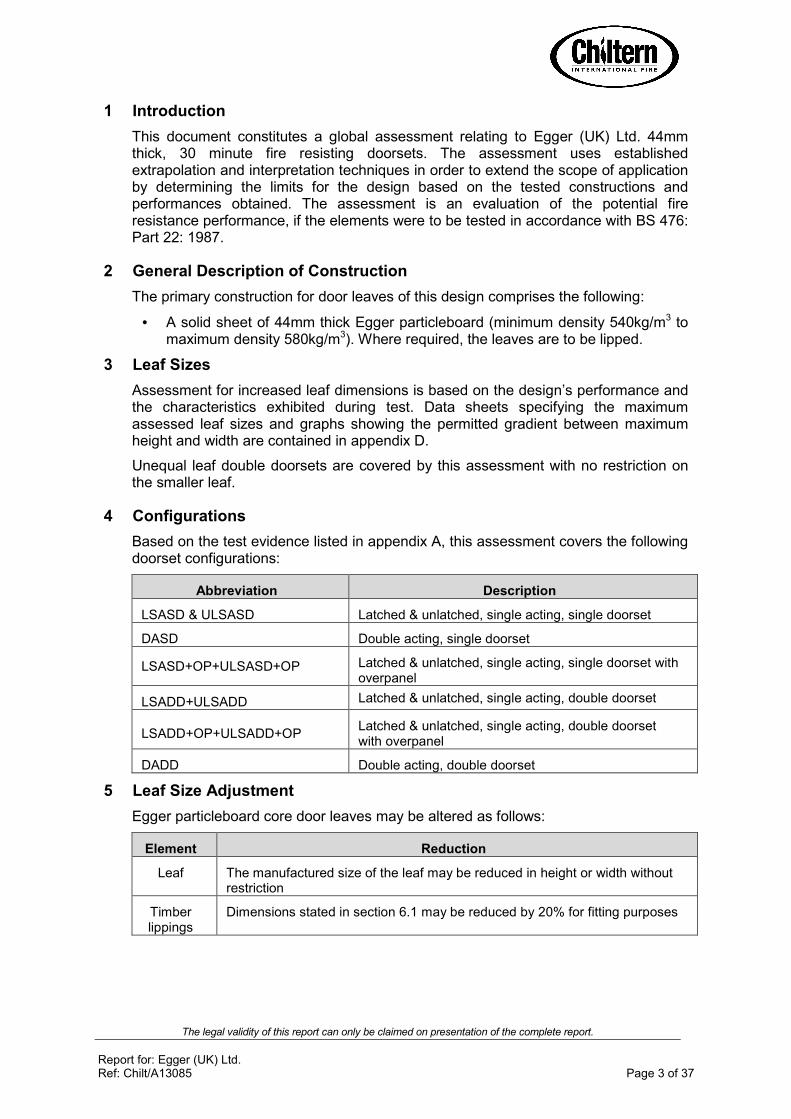
Overpanels of the same construction as the door leaves may be used with this doorset design, either with or without a transom between the leaf head and overpanel. When transomed, a transom to the same specification as the timber door frame must separate the leaf heads from the overpanel.
Door frame joints for overpanels must utilise one of the following four methods: mortice and tenon joints; half lapped joints; mitre joints or butt joints (see section 7.3). All methods require joints to be tight, with no gaps, and require mechanical fixing with the appropriate size ring shank nails or screws. Butt joints must be additionally bonded with urea formaldehyde or equivalent.
Overpanels must be fixed by steel screws through the rear of the frame penetrating at least 30mm centrally into all edges of the overpanel. Fixings must be no more than 100mm from each corner and a maximum of 400mm centres in between.
The intumescent seals required for concealed overpanel edges are as for the jamb seals and are specified in appendix D. The seals may be fitted in the overpanel edges or alternatively in the frame reveal. Providing the seals are fitted to all concealed edges of the overpanel, the gap between the overpanel and frame is permitted to have a 2mm gap tolerance.
Maximum overpanel heights are as follows:
• Single doorsets A 2000mm
• Double doorsets A 1500mm
Note: Drawing is representative of doorset construction only; actual construction must be as the text within this document specifies.
Leaf head
Transom
Overpanel fixings
Intumescent seals

The legal validity of this report can only be claimed on presentation of the complete report.
Report for: Egger (UK) Ltd. Ref: Chilt/A13085 Page 9 of 37
9.2 Glazed Fanlights
Timber frame doorsets including a transom may have the overpanel section glazed in lieu of a section of door. The glazing system and glass must be able to demonstrate adequate performance when tested as a window or screen in accordance with BS 476: Part 22: 1987 or BS EN 1634A1: 2000 or 2008. The timber frame and glazing beads must be hardwood with a minimum density of 640kg/m3 and the frame sections must be a minimum of 70mm x 44mm. MDF frame sections are not assessed for glazed fanlights.
The maximum assessed fanlight dimensions are detailed in the table below:
Configuration Height (mm) Width (mm)
Single & double doorsets ≤600 Overall door width
Note: Drawing is representative of doorset construction only; actual construction must be as the text within this document specifies.
Bead fixings
Assessed glass type
Glazing seal
Transom
Leaf head
The legal validity of this report can only be claimed on presentation of the complete report.
Report for: Egger (UK) Ltd. Ref: Chilt/A13085 Page 10 of 37
10 Glazing
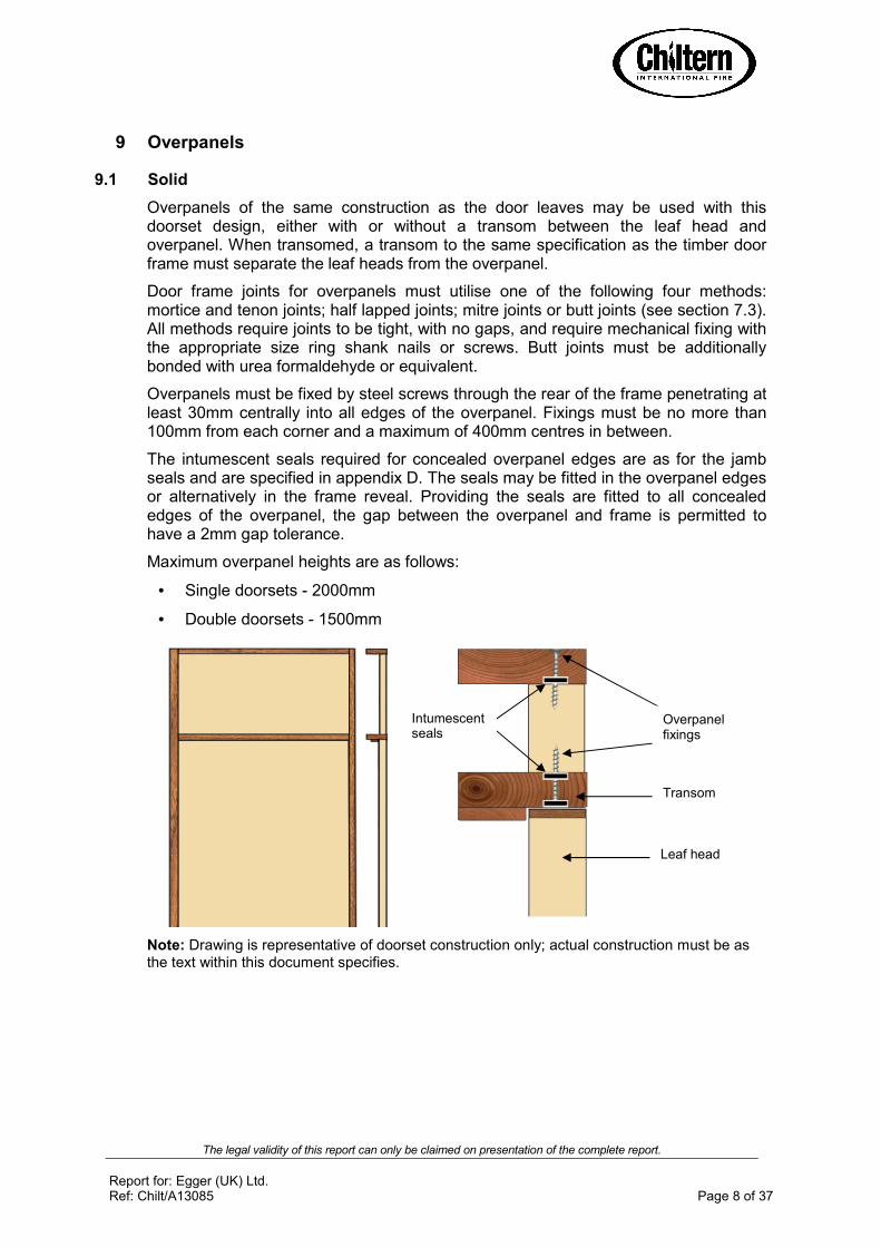
10.1 General
The testing conducted on the Egger particleboard core door leaf has demonstrated that the design is capable of tolerating glazed apertures, whilst providing a margin of over performance. The maximum assessed glazed area is 1.29m2.
Glazing is therefore acceptable within the following parameters:
10.2 Assessed Glazing Systems
The glazing system must be one of the following tested proprietary systems:
Glazing System Manufacturer
1. ThermAAAStrip Intumescent Seals Ltd.
2. Fireglaze 30 Sealmaster Ltd.
3. Firestrip 30 Hodgsons Sealants Ltd.
4. Pyroglaze 30 Mann McGowan Ltd.
5. R8193 Pyroplex Ltd.
6. System 36+ Lorient Polyproducts Ltd.
7. Flexible Figure 1 Lorient Polyproducts Ltd.
10.3 Assessed Glass Products
Glass Type Manufacturer Thickness (mm) Max. Area (m²)
1. Pyroshield Pilkington Group Ltd. 6 & 7 1.29
2. Pyroshield II Pilkington Group Ltd. 6 & 7 1.29
3. Pyran S Schott UK Ltd. 6 1.29
4. Pyrostem CGI Ltd. 6 1.29
5. Pyroguard EW30 CGI Ltd. 7 0.87
6. Pyrobelite 7 AGC Flat Glass UK 7 1.29
7. Pyrodur 30A104 Pilkington Group Ltd. 7 1.29
8. Pyrodur 60A10 Pilkington Group Ltd. 10 1.29
9. Pyroguard EW MAXI CGI Ltd. 11 0.58
10. Pyranova 15AS2.0 Schott UK Ltd. 11 1.29
11. Pyrobelite 12 AGC Flat Glass UK 12 1.29
12. Pyrodur 60A20 Pilkington Group Ltd. 13 1.29
13. Swissflam Lite Vetrotech Saint Gobain AG 14 1.29
14. Pyroguard EI30 CGI Ltd. 15 0.54
15. Pyrostop 30A10 Pilkington Group Ltd. 15 1.29
16. Pyrobel 16 AGC Flat Glass UK 16 1.29
Note: All glass types must be fitted fully in accordance with the manufacturers' tested details/installation requirements, particularly with respect to edge cover and expansion clearance.
The legal validity of this report can only be claimed on presentation of the complete report.
Report for: Egger (UK) Ltd. Ref: Chilt/A13085 Page 11 of 37
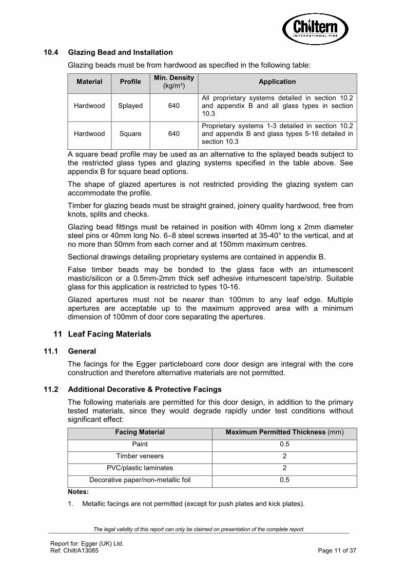
10.4 Glazing Bead and Installation
Glazing beads must be from hardwood as specified in the following table:
Material Profile Min. Density
(kg/m³) Application
Hardwood Splayed 640 All proprietary systems detailed in section 10.2 and appendix B and all glass types in section 10.3
Hardwood Square 640 Proprietary systems 1A3 detailed in section 10.2 and appendix B and glass types 5A16 detailed in section 10.3
A square bead profile may be used as an alternative to the splayed beads subject to the restricted glass types and glazing systems specified in the table above. See appendix B for square bead options.
The shape of glazed apertures is not restricted providing the glazing system can accommodate the profile.
Timber for glazing beads must be straight grained, joinery quality hardwood, free from knots, splits and checks.
Glazing bead fittings must be retained in position with 40mm long x 2mm diameter steel pins or 40mm long No. 6–8 steel screws inserted at 35A40° to the vertical, and at no more than 50mm from each corner and at 150mm maximum centres.
Sectional drawings detailing proprietary systems are contained in appendix B.
False timber beads may be bonded to the glass face with an intumescent mastic/silicon or a 0.5mmA2mm thick self adhesive intumescent tape/strip. Suitable glass for this application is restricted to types 10A16.
Glazed apertures must not be nearer than 100mm to any leaf edge. Multiple apertures are acceptable up to the maximum approved area with a minimum dimension of 100mm of door core separating the apertures.
11 Leaf Facing Materials
11.1 General
The facings for the Egger particleboard core door design are integral with the core construction and therefore alternative materials are not permitted.
11.2 Additional Decorative & Protective Facings
The following materials are permitted for this door design, in addition to the primary tested materials, since they would degrade rapidly under test conditions without significant effect:
Facing Material Maximum Permitted Thickness (mm)
Paint 0.5
Timber veneers 2
PVC/plastic laminates 2
Decorative paper/nonAmetallic foil 0.5
Notes:
1. Metallic facings are not permitted (except for push plates and kick plates).

The legal validity of this report can only be claimed on presentation of the complete report.
Report for: Egger (UK) Ltd. Ref: Chilt/A13085 Page 12 of 37
2. The door leaf thickness may be reduced by a total maximum of 0.5mm for calibration purposes in order to accommodate the chosen finish.
3. Materials must not conceal intumescent strips.
4. PVC/ABS may be applied to the edges of this door design meeting the specification given in section 6.2.
12 Adhesives
The following adhesives must be used in construction of this doorset design:
Element Product/Manufacturer
Timber lippings PVA, Polyurethane, Urea/Phenol formaldehyde
ABS lipping PVA
13 Tested Hardware
The following hardware has been successfully incorporated in the tests on this design:
Element Make/type Size (mm) Location
Hinges
Royde and Tucker H105 liftAoff type
101 x 32 (blade size)
See section 14.2 Hafele bearing butt type
hinge ref: 926.90.203 101 x 30 (blade
size)
Closers
Dorma Door Controls TS68
220 x 54 (foot print size)
Fitted to exposed face of leaf as per
manufacturer’s specification
Hafele overhead type closer Ref: 931.16.169
230 x 68 (footprint size)
Locks/latches
Henderson Hardware Tubular mortice latch
57 x 26 (forend size) Fitted in leaf edge 1000mm up from
threshold Eurospec EasiAT mortice sash lock
235 x 24 (forend size)
175 x 38 (keep size)
Furniture
Aluminium lever type handle
100 x 38 (footprint size)
Fitted appropriate to the latch
Handle and lock escutcheon:
Eurospec EasiAT mortice sashlock set
52 diameter rose
Eurocylinder: Eurospec EasiAT
mortice sashlock set 80 long
Floor Springs Dorma Door Controls
BTS80F 341 long x 78 wide x
60 deep
Fitted as per manufacturer’s specification
Top Pivots Dorma Door Controls
8067 165 long x 25 wide
Fitted as per manufacturer’s specification
Drop down seal
Hafele Ref: 950.07.546 33.5 high x 15 wide Fitted at the
threshold
Flush bolt Hafele Ref: 911.62.125 200 long x 24 wide x
30 deep Fitted at the
threshold

The legal validity of this report can only be claimed on presentation of the complete report.
Report for: Egger (UK) Ltd. Ref: Chilt/A13085 Page 13 of 37
14 Additional & Alternative Hardware
14.1 Latches & Locks
Latches and locks must either be as tested, or alternatively components with the following specification are acceptable:
Maximum forend and strike plate dimensions
235mm high by 25mm wide by 4mm thick
Maximum body dimensions
180mm high by 150mm wide by 18mm thick
Intumescent protection See section 8
Materials All parts essential to the locking/latching action (including
the latch bolt, forend and strike) to be steel
Maximum height of threshold
1200mm
14.2 Hinges
Egger particleboard core door designs must be hung on a minimum of 3 hinges. Leaves over 2440mm high must fit 4 hinges. Hinges with the following specification are acceptable:
Blade height 90 – 120mm
Blade width (excluding knuckle)
30 – 35mm
Blade thickness 2.5 A 4mm
Fixings Minimum of 4No. 30mm long No. 8 A 10 steel wood screws per blade
Materials Steel, stainless steel, or brass (melting point = or >800°C)
Hinge positions
If 3 hinges are required
Top 150A180mm from the head to top of hinge
2nd
Equispaced between top and bottom
Bottom 150A250mm from the foot of leaf to bottom of hinge
If 4 hinges are required
Top 100A180mm from the head to top of hinge
2nd
& 3
rd
Equispaced between top and bottom or 2nd
hinge 200mm from top hinge and 3
rd hinge
equally spaced between 2nd
and bottom hinge
Bottom 180A250mm from the foot of leaf to bottom of hinge
Intumescent protection See section 8

The legal validity of this report can only be claimed on presentation of the complete report.
Report for: Egger (UK) Ltd. Ref: Chilt/A13085 Page 14 of 37
14.3 Automatic Closing
Automatic closing devices must either be as tested, or components of equal specification that have demonstrated contribution to the required integrity performance of these types of doorset design, when tested to BS 476: Part 22: 1987 or BS EN 1634A1: 2000 or 2008.
Note: The top and bottom pivots to floor spring assemblies must be protected with intumescent gaskets (see section 8).
14.4 Flush Bolts
Flush bolts may be incorporated into the top and bottom of the meeting edge of the inactive leaf of a double doorset, provided that the following maximum dimensions are not exceeded and they are located opposite the leaf edge fitted with intumescent strips:
200mm long x 20mm deep x 20mm wide
Flush bolts must be steel or brass and the mortice must be as tight to the mechanism as is compatible with its operation. All edges of the mortice must be lined with an intumescent gasket (see section 8). See diagram below for example of intumescent protection to flush bolt:
14.5 Pull Handles
These may be surfaceAfixed to the door leaf provided that they are steel or brass and the length is limited to 1200mm between the fixing points. No additional intumescent protection is required provided that the hole for the bolt through the leaf is tight.
14.6 Push Plates/Kick Plates
FaceAfixed hardware such as push plates and kick plates may be fitted to the doorsets provided that their fitting requires the removal of no part of the door leaf. These items of hardware must not amount to more than 20% of the door leaf area.
Door leaf
Flush bolt mechanism
Intumescent gaskets

The legal validity of this report can only be claimed on presentation of the complete report.
Report for: Egger (UK) Ltd. Ref: Chilt/A13085 Page 15 of 37
14.7 Door Selectors
These may be freely applied, provided that they are not invasive in the leaf edges or door frames. Those that are invasive will require fire resistance test/assessment evidence to support their use. No additional intumescent protection is required unless test evidence dictates otherwise.
14.8 Door Security Viewers
Door security viewers with brass or steel bodies of a diameter less than or equal to 15mm may be used provided that the throughAhole is bored tight to the case of the viewer (maximum tolerance +1mm). Lenses must be glass and the item must be bedded in to a tested intumescent acrylic mastic.
14.9 Panic Hardware
Panic hardware may be fitted, provided that its installation does not require the removal of any timber from the leaf, stop or frame reveal and it in no way interferes with the selfAclosing action of the door leaf.
14.10 Air Transfer Grilles
Air transfer grilles may be fitted providing the product has suitable test evidence to BS 476: Part 22: 1987 or BS EN 1634A1: 2000 or 2008, that demonstrates the required integrity performance when installed within a timber based doorset of comparable thickness. Margins to the leaf edges will remain as detailed for glazing and the position of the unit will be dictated by the pressure regime tested in the proving evidence (normally below midAheight). The area occupied by the air transfer grille must not exceed 0.2m2 and must be deducted from the percentage of glazing, if both elements are fitted.
14.11 Acoustic, Weather and Dust Seals
Silicon based flame retardant acoustic, weather and dust seals (e.g. Norseal 710, Lorient IS1212, IS1511, IS7025, IS7060) may be fitted to this doorset design without compromising the performance, providing their fitting does not interfere with the activation of the intumescent seals or hinder the self closing function of the leaves.
14.12 Threshold Seals
The following types of automatic threshold drop seals may be recessed in to the bottom rail of leaves to this design without compromising the performance:
Manufacturer Product
Lorient Polyproducts Ltd. IS8010si
Lorient Polyproducts Ltd. IS8005si
Raven Products RP8Si
Athmer SchallAEx Duo LA15
Norseal Ltd. 810
Hafele Ltd. 950.07.546
Alternative products may be used providing they are essentially of the same construction, materials and dimensions.

The legal validity of this report can only be claimed on presentation of the complete report.
Report for: Egger (UK) Ltd. Ref: Chilt/A13085 Page 16 of 37
14.13 CableBWay
Based on the integrity performance of the doorset construction, with no burn through of the core material, we consider it acceptable to allow the provision for a concealed cableAway to facilitate electroAmagnetic closing/latching mechanisms. The cableAway must be concealed in the following way:
1. A hole drilled centrally through the leaf of maximum 10mm diameter;
2. The cable for the electronic closing/latching mechanisms must be no more than 2mm smaller in diameter than the hole through the leaf;
3. The cable for the electronic closing/latching mechanism must be PVC encased;
4. Cable ways are only permitted for use with latched, single leaf, single acting doorsets with maximum leaf dimensions of 2100mm (h) x 900mm (w);
5. The hole must be located below 1500mm from the threshold and must be spaced a minimum of 90mm from any apertures within the leaf, e.g. glazing, air transfer grilles or letter plates, etc.
This approval is subject to the hardware manufacturer having the appropriate test evidence for the product for use with this type of 30 minute construction. Test evidence generated in steel doorsets is not acceptable. Any tested intumescent gaskets for the lockset, closing mechanism, receiver plate, cable loops, etc. must be replicated.
14.14 Letter Boxes/Plates
Letter boxes/plates may be fitted providing the product can demonstrate contribution to the required integrity performance of this type of doorset design, and tested to BS 476: Part 22: 1987 or BS EN 1634A1: 2000 or 2008, when installed within a timber based doorset of comparable thickness. Margins to the leaf edges must remain as detailed for glazing. The position of the letter box/plate will be dictated by the pressure regime tested in the proving evidence (normally below midAheight).
15 Door Gaps
If gaps are substantially different to those in the tested specimens, the fire resistance performance of this doorset design may change. The following table is presented for guidance:
Location Dimensions
Door edge gaps Representative of those tested but as a guideline, a minimum of 2mm and a maximum of 4mm
Alignment tolerances Leaves must not be proud of each other or from the door frame by more than 1mm
Threshold 10mm between bottom of leaf and top of floor covering
16 Classification of Timber
All timber used for door frames (softwood/hardwood as applicable) must meet or exceed class J30 as specified in BS EN 942: 2007, providing any defects are adequately repaired.

The legal validity of this report can only be claimed on presentation of the complete report.
Report for: Egger (UK) Ltd. Ref: Chilt/A13085 Page 17 of 37
17 Fixings
The supporting construction must be capable of staying in place and intact for the full period of fire resistance required from the doorset. The frame jambs are to be fixed to the supporting construction using steel fixings at 600mm maximum centres. The fixings must be of the appropriate type for the supporting construction and must penetrate to a minimum depth of 40mm. It is not necessary to fix the frame head, although packers must be inserted.
18 Sealing to Structural Opening
The door frame to structural opening gap must be protected using one of the following methods:
1. Gaps up to 10mm must be sealed on both sides with a 10mm depth of acrylic intumescent mastic, fire tested for this application to BS 476: Part 22: 1987 or BS EN 1634A1: 2000 or 2008. Joint must be fitted with 15mm thick architraves overlapping at least 15mm each side.
2. Gaps between 10mm and 20mm must be tightly packed with mineral fibre capped on both sides with a 10mm depth of acrylic intumescent mastic, fire tested for this application to BS 476: Part 22: 1987 or BS EN 1634A1: 2000 or 2008. Architraves are optional.
3. Gaps up to 20mm filled with proprietary fire stopping product (e.g. expanding PU foam or preformed compressible intumescent foam). Products must be tested for this application to BS 476: Part 22: 1987 or BS EN 1634A1: 2000 or 2008. Joint must be fitted with 15mm thick architraves overlapping at least 15mm each side.
Architrave for joints not filled with mineral wool and optional for filled joints
Frame fixing Mineral fibre infill for joints exceeding 10mm
Acrylic intumescent mastic
Fire stopping product
Frame fixing Architrave
The legal validity of this report can only be claimed on presentation of the complete report.
Report for: Egger (UK) Ltd. Ref: Chilt/A13085 Page 18 of 37
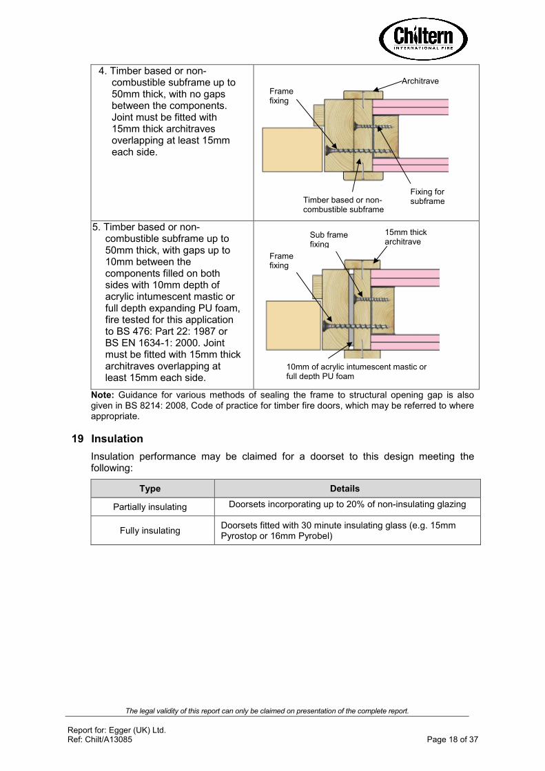
4. Timber based or nonAcombustible subframe up to 50mm thick, with no gaps between the components. Joint must be fitted with 15mm thick architraves overlapping at least 15mm each side.
5. Timber based or nonAcombustible subframe up to 50mm thick, with gaps up to 10mm between the components filled on both sides with 10mm depth of acrylic intumescent mastic or full depth expanding PU foam, fire tested for this application to BS 476: Part 22: 1987 or BS EN 1634A1: 2000. Joint must be fitted with 15mm thick architraves overlapping at least 15mm each side.
Note: Guidance for various methods of sealing the frame to structural opening gap is also given in BS 8214: 2008, Code of practice for timber fire doors, which may be referred to where appropriate.
19 Insulation
Insulation performance may be claimed for a doorset to this design meeting the following:
Type Details
Partially insulating Doorsets incorporating up to 20% of nonAinsulating glazing
Fully insulating Doorsets fitted with 30 minute insulating glass (e.g. 15mm Pyrostop or 16mm Pyrobel)
Timber based or nonAcombustible subframe
Architrave
Fixing for subframe
Frame fixing
15mm thick architrave
10mm of acrylic intumescent mastic or full depth PU foam
Frame fixing
Sub frame fixing

The legal validity of this report can only be claimed on presentation of the complete report.
Report for: Egger (UK) Ltd. Ref: Chilt/A13085 Page 19 of 37
20 Smoke Control
20.1 General
If the doorset design is required to provide a smoke control function to comply with Building Regulations, in the absence of a suitable pressurisation system, the doorset must meet one of the following criteria:
(a) have a leakage rate not exceeding 3m3/m/hour (head and jambs only) when tested at 25Pa under BS 476 Fire tests on building materials and structures, Section 31.1 A Methods for measuring smoke penetration through doorsets and shutter assemblies, Method of measurement under ambient temperature conditions; or
(b) meet the additional classification requirement of Sa when tested to BS EN 1634A3: 2001 A Fire resistance tests for door and shutter assemblies, Part 3 – Smoke control doors.
Smoke seals or combined intumescent/smoke seals that are fitted to the door to achieve the performance requirements specified above, must have been tested in accordance with the associated test method. Providing the smoke seals, any interruptions, door gaps, and the type/configuration of the doorset are consistent with the detail tested, the doorset will comply with current smoke control legislation under approved document B; and a suffix ‘S’ or ‘Sa’, as appropriate, may be added to the designation. Any other components installed where smoke leakage may occur must also be taken into account.
Note: The incorrect specification and fitting of smoke seals may impair the operation of a doorset and therefore compromise the fire resistance performance. Advice should be sought from the seal manufacturers regarding the correct specification and installation of smoke seals or combined smoke and intumescent seals.
20.2 Further Considerations
Note that there is other guidance available, including BS EN 9999A2008 A Code of practice for fire safety in the design, management and use of buildings, which may impose different or additional requirements, such as consideration of the gap between door leaf and threshold.
Responsibility for the appropriate smoke sealing specification and performance of the doors should be agreed between the relevant parties (i.e. specifier, manufacturer, contractor) prior to commencing manufacture and/or installation.
21 Conclusion
If the Egger particleboard core doorset design, constructed in accordance with the specification documented in this global assessment, were to be tested in accordance with BS 476: Part 22: 1987, it is our opinion that it would provide a minimum of 30 minutes integrity and insulation (subject to section 19).

The legal validity of this report can only be claimed on presentation of the complete report.
Report for: Egger (UK) Ltd. Ref: Chilt/A13085 Page 20 of 37
22 Declaration by the Applicant
1) We the undersigned confirm that we have read and comply with obligations placed on us by FTSG Resolution No. 82: 2001.
2) We confirm that the component or element of structure, which is the subject of this assessment, has not to our knowledge been subjected to a fire test to the Standard against which this assessment is being made.
3) We agree to withdraw this assessment from circulation should the component or element of structure be the subject of a fire test to the Standard against which this assessment is being made.
4) We are not aware of any information that could adversely affect the conclusions of this assessment.
5) If we subsequently become aware of any such information we agree to ask the assessing authority to withdraw the assessment.
Signed:
Name:
For and on behalf of: EGGER (UK) Ltd.
The legal validity of this report can only be claimed on presentation of the complete report.
Report for: Egger (UK) Ltd. Ref: Chilt/A13085 Page 21 of 37
23 Limitations
The following limitations apply to this assessment:
1) This assessment addresses itself solely to the elements and subjects discussed and does not cover any other criteria. All other details not specifically referred to should remain as tested or assessed.
2) This assessment is issued on the basis of test data and information to hand at the time of issue. If contradictory evidence becomes available, CIF reserves the right to withdraw the assessment unconditionally but not retrospectively.
3) This assessment has been carried out in accordance with Fire Test Study Group Resolution No. 82: 2001.
4) Opinions and interpretations expressed herein are outside the scope of UKAS accreditation.
5) This assessment relates only to those aspects of design, materials and construction that influence the performance of the element(s) under fire resistance test conditions. It does not purport to be a complete specification ensuring fitness for purpose and longAterm serviceability. It is the responsibility of the client to ensure that the element conforms to recognised good practice in all other respects and that, with the incorporation of the guidance given in this assessment, the element is suitable for its intended purpose.
24 Validity
1) The assessment is initially valid for five years after which time it must be submitted to CIFL for reAappraisal.
2) This assessment report is not valid unless it incorporates the declaration given in Section 22, duly signed by the applicant.
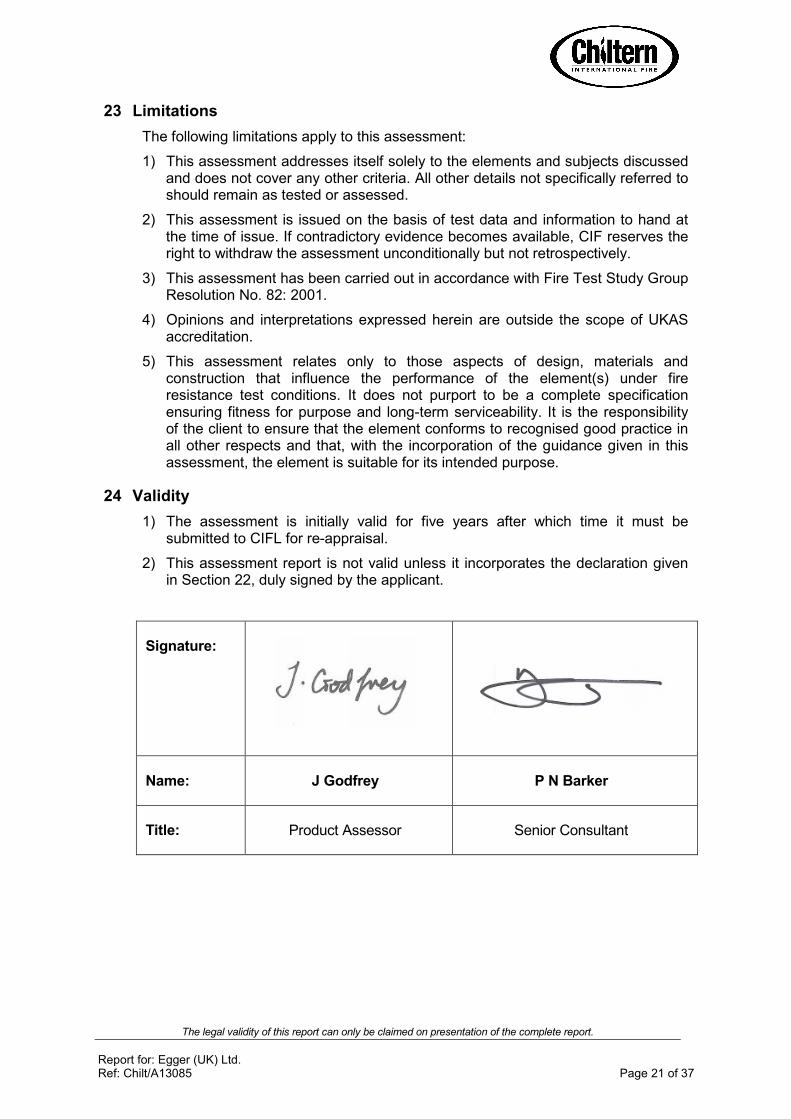
Signature:
Name: J Godfrey P N Barker
Title: Product Assessor Senior Consultant
The legal validity of this report can only be claimed on presentation of the complete report.
Report for: Egger (UK) Ltd. Ref: Chilt/A13085 Page 22 of 37
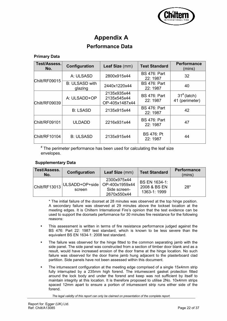
Appendix A
Performance Data
Primary Data
Test/Assess. No.
Configuration Leaf Size (mm) Test Standard Performance
(mins)
Chilt/RF09015 A: ULSASD 2800x915x44
BS 476: Part 22: 1987
32
B: ULSASD with glazing
2440x1220x44 BS 476: Part
22: 1987 40
Chilt/RF09039 A: ULSADD+OP
2135x935x44 2135x545x44
OPA405x1487x44
BS 476: Part 22: 1987
31# (latch) 41 (perimeter)
B: LSASD 2135x915x44 BS 476: Part
22: 1987 42
Chilt/RF09101 ULDADD 2216x931x44 BS 476: Part
22: 1987 47
Chilt/RF10104 B: ULSASD 2135x915x44 BS 476: Pt 22: 1987
44
# The perimeter performance has been used for calculating the leaf size envelopes.
Supplementary Data
Test/Assess. No.
Configuration Leaf Size (mm) Test Standard Performance
(mins)
Chilt/RF13013 ULSADD+OP+side
screen
2300x975x44 OPA400x1959x44
Side screenA2670x550x44
BS EN 1634A1: 2008 & BS EN 1363A1: 1999
28*
* The initial failure of the doorset at 28 minutes was observed at the top hinge position. A secondary failure was observed at 29 minutes above the lockset location at the meeting edges. It is Chiltern International Fire’s opinion that the test evidence can be used to support the doorsets performance for 30 minutes fire resistance for the following reasons:
• This assessment is written in terms of fire resistance performance judged against the BS 476: Part 22: 1987 test standard, which is known to be less severe than the equivalent BS EN 1634A1: 2008 test standard.
• The failure was observed for the hinge fitted to the common separating jamb with the side panel. The side panel was constructed from a section of timber door blank and as a result, would have increased erosion of the door frame at the hinge location. No such failure was observed for the door frame jamb hung adjacent to the plasterboard clad partition. Side panels have not been assessed within this document.
• The intumescent configuration at the meeting edge comprised of a single 15x4mm strip fully interrupted by a 235mm high forend. The intumescent gasket protection fitted around the lock body and under the forend and keep was not sufficient by itself to maintain integrity at this location. It is therefore proposed to utilise 2No. 10x4mm strips spaced 12mm apart to ensure a portion of intumescent strip runs either side of the forend.

The legal validity of this report can only be claimed on presentation of the complete report.
Report for: Egger (UK) Ltd. Ref: Chilt/A13085 Page 23 of 37
Appendix B
Proprietary 30 Minute Glazing Systems
1 0 A15 °
515
A ss es se d g lassH o dg son s
F ire s tr ip 30
F ire s tr ip 3 0
H o d g s o n s S e a la n ts L td
5 0m m p ins
o r 40 m m s c rew s40mm pins or screws
System 36+ gasket
System 36+ Lorient Polyproducts Ltd.

The legal validity of this report can only be claimed on presentation of the complete report.
Report for: Egger (UK) Ltd. Ref: Chilt/A13085 Page 24 of 37
Assessed Square Glazing Bead Profiles The following square bead profiles may be used as an alternative to the splayed beads detailed above A refer to section 10 for glazing system and glass restrictions.
3
3
15
5
5
Suited to glass thickness
15
To finish flush with the leaf face
15
To finish flush with the leaf face

The legal validity of this report can only be claimed on presentation of the complete report.
Report for: Egger (UK) Ltd. Ref: Chilt/A13085 Page 25 of 37
Appendix C
Revisions
Revision Date Description

The legal validity of this report can only be claimed on presentation of the complete report.
Report for: Egger (UK) Ltd. Ref: Chilt/A13085 Page 26 of 37
Appendix D
Data Sheets for:
EGGER (UK) Ltd.
Egger 44mm FD30 Door Blank
30 Minutes Fire Resistance

The legal validity of this report can only be claimed on presentation of the complete report.
Report for: Egger (UK) Ltd. Ref: Chilt/A13085 Page 27 of 37
Maximum Door Leaf Size
2400
2500
2600
2700
2800
2900
3000
3100
12001300140015001600
Width (mm)
He
igh
t (m
m)
DASD & ULSASD LSASD
Egger 44mm FD30 Door Blank – Type 617
Latched & Unlatched, Single & Double Acting, Single Doorsets
Leaf Sizes
Configuration Height (mm) Width (mm)
DASD & ULSASD
From: To:
2440 x 1525
3050 x 1220
LSASD From:
To:
2440 x 1550
3100 x 1220
Maximum Overpanel Height (mm) Transomed 2000
Intumescent Materials: Lorient Polyproducts Ltd. Type 617
Head: 1No. 15x4mm centrally fitted in the leaf edge or frame reveal. For leaves over 2440mm high, increase this to 1No.
20x4mm. Jambs: 1No. 15x4mm centrally fitted in the leaf edge or frame reveal. Hardware Protection: See section 8. Note, for leaves over 2440mm high, intumescent protection is required under the hinge blades on both leaf and frame.

The legal validity of this report can only be claimed on presentation of the complete report.
Report for: Egger (UK) Ltd. Ref: Chilt/A13085 Page 28 of 37
Maximum Door Leaf Size
2200
2300
2400
2500
2600
2700
2800
2900
3000
3100
3200
3300
90010001100120013001400
Width (mm)
He
igh
t (m
m)
DASD & ULSASD LSASD
Egger 44mm FD30 Door Blank – Type 617
Latched & Unlatched, Single & Double Acting, Single Doorsets
Leaf Sizes
Configuration Height (mm) Width (mm)
DASD & ULSASD
From: To:
2216 x 1372
3246 x 931
LSASD From:
To:
2216 x 1397
3296 x 931
Maximum Overpanel Height (mm) Transomed 2000
Intumescent Materials: Lorient Polyproducts Ltd. Type 617
Head: 1No. 15x4mm centrally fitted in the leaf edge or frame reveal. For leaves over 2440mm high, increase this to 1No.
20x4mm. Jambs: 1No. 15x4mm centrally fitted in the leaf edge or frame reveal. Hardware Protection: See section 8. Note, for leaves over 2440mm high, intumescent protection is required under the hinge blades on both leaf and frame.

The legal validity of this report can only be claimed on presentation of the complete report.
Report for: Egger (UK) Ltd. Ref: Chilt/A13085 Page 29 of 37
Maximum Door Leaf Size
2100
2200
2300
2400
2500
2600
2700
2800
2900
3000
3100
90010001100120013001400
Width (mm)
He
igh
t (m
m)
DASD & ULSASD LSASD
Egger 44mm FD30 Door Blank – Pyrostrip 100P
Latched & Unlatched, Single & Double Acting, Single Doorsets
Leaf Sizes
Configuration Height (mm) Width (mm)
DASD & ULSASD
From: To:
2135 x 1337
3011 x 935
LSASD From:
To:
2135 x 1362
3061 x 935
Maximum Overpanel Height (mm) Transomed 2000
Intumescent Materials: Mann McGowan Ltd. – Pyrostrip 100P
Head: 1No. 15x4mm centrally fitted in the leaf edge or frame reveal. For leaves over 2440mm high, increase this to 1No.
20x4mm. Jambs: 1No. 15x4mm centrally fitted in the leaf edge or frame reveal. Hardware Protection: See section 8. Note, for leaves over 2440mm high, intumescent protection is required under the hinge blades on both leaf and frame.

The legal validity of this report can only be claimed on presentation of the complete report.
Report for: Egger (UK) Ltd. Ref: Chilt/A13085 Page 30 of 37
Maximum Door Leaf Size
2250
2350
2450
2550
2650
9501000105011001150
Width (mm)
He
igh
t (m
m)
DASD & ULSASD LSASD
Egger 44mm FD30 Door Blank – Pyroplex
Latched & Unlatched, Single & Double Acting, Single Doorsets
Leaf Sizes
Configuration Height (mm) Width (mm)
DASD & ULSASD
From: To:
2300 x 1125
2600 975
LSASD From:
To:
2300 x 1150
2650 x 975
Maximum Overpanel Height (mm) Transomed 2000
Intumescent Materials: Pyroplex Ltd. – Pyroplex Rigid Box Seals
Head: 1No. 20x4mm centrally fitted in the leaf head or frame reveal. Jambs: 1No. 15x4mm centrally fitted in the leaf edge or frame reveal. Hardware Protection: See section 8. Note, for leaves over 2440mm high, intumescent protection is required under the hinge blades on both leaf and frame.
The legal validity of this report can only be claimed on presentation of the complete report.
Report for: Egger (UK) Ltd. Ref: Chilt/A13085 Page 31 of 37
Maximum Door Leaf Size
2100
2200
2300
2400
2500
2600
2700
2800
2900
3000
90095010001050110011501200125013001350
Width (mm)
He
igh
t (m
m)
ULSASD+OP LSASD+OP
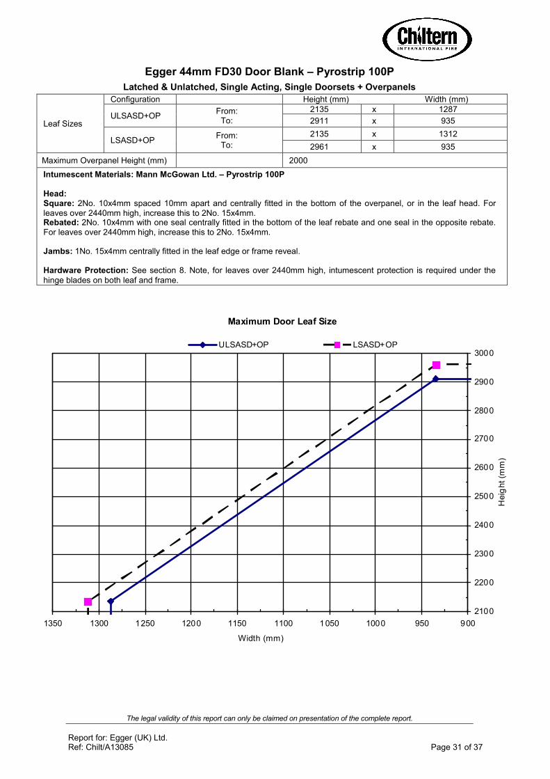
Egger 44mm FD30 Door Blank – Pyrostrip 100P
Latched & Unlatched, Single Acting, Single Doorsets + Overpanels
Leaf Sizes
Configuration Height (mm) Width (mm)
ULSASD+OP From:
To:
2135 x 1287
2911 x 935
LSASD+OP From:
To:
2135 x 1312
2961 x 935
Maximum Overpanel Height (mm) 2000
Intumescent Materials: Mann McGowan Ltd. – Pyrostrip 100P
Head: Square: 2No. 10x4mm spaced 10mm apart and centrally fitted in the bottom of the overpanel, or in the leaf head. For leaves over 2440mm high, increase this to 2No. 15x4mm. Rebated: 2No. 10x4mm with one seal centrally fitted in the bottom of the leaf rebate and one seal in the opposite rebate. For leaves over 2440mm high, increase this to 2No. 15x4mm. Jambs: 1No. 15x4mm centrally fitted in the leaf edge or frame reveal. Hardware Protection: See section 8. Note, for leaves over 2440mm high, intumescent protection is required under the
hinge blades on both leaf and frame.

The legal validity of this report can only be claimed on presentation of the complete report.
Report for: Egger (UK) Ltd. Ref: Chilt/A13085 Page 32 of 37
Maximum Door Leaf Size
2250
2300
2350
2400
2450
2500
2550
2600
950975100010251050107511001125
Width (mm)
He
igh
t (m
m)
ULSASD+OP LSASD+OP
Egger 44mm FD30 Door Blank – Pyroplex
Latched & Unlatched, Single Acting, Single Doorsets + Overpanels
Leaf Sizes
Configuration Height (mm) Width (mm)
ULSASD+OP From:
To:
2300 x 1075
2500 975
LSASD+OP From:
To:
2300 x 1100
2550 x 975
Maximum Overpanel Height (mm) 2000
Intumescent Materials: Pyroplex Ltd. – Pyroplex Rigid Box Seals
Head: Square: 2No. 15x4mm spaced 7mm apart and centrally fitted in the bottom of the overpanel, or in the leaf head. Rebated: 2No. 15x4mm with one seal centrally fitted in the bottom of the leaf rebate and one seal in the opposite rebate. Jambs: 1No. 15x4mm centrally fitted in the leaf edge or frame reveal. Hardware Protection: See section 8. Note, for leaves over 2440mm high, intumescent protection is required under the hinge blades on both leaf and frame.

The legal validity of this report can only be claimed on presentation of the complete report.
Report for: Egger (UK) Ltd. Ref: Chilt/A13085 Page 33 of 37
Maximum Door Leaf Size
2100
2200
2300
2400
2500
2600
2700
2800
2900
9009501000105011001150120012501300
Width (mm)
He
igh
t (m
m)
DADD & ULSADD LSADD
Egger 44mm FD30 Door Blank – Pyrostrip 100P
Latched & Unlatched, Single & Double Acting, Double Doorsets
Leaf Sizes
Configuration Height (mm) Width (mm)
DADD & ULSADD
From: To:
2135 x 1237
2811 x 935
LSADD From:
To:
2135 x 1262
2861 x 935
Maximum Overpanel Height (mm) Transomed 1500
Intumescent Materials: Mann McGowan Ltd. – Pyrostrip 100P
Head: 1No. 15x4mm centrally fitted in the leaf edge or frame reveal. For leaves over 2440mm high, increase this to 1No.
20x4mm. Meeting Edges: 1No. 15x4mm centrally fitted in the meeting edge of one leaf only. Jambs: 1No. 15x4mm centrally fitted in the leaf edge or frame reveal. Hardware Protection: See section 8. Note, for leaves over 2440mm high, intumescent protection is required under the hinge blades on both leaf and frame.
The legal validity of this report can only be claimed on presentation of the complete report.
Report for: Egger (UK) Ltd. Ref: Chilt/A13085 Page 34 of 37
Maximum Door Leaf Size
2200
2300
2400
2500
2600
2700
2800
2900
3000
3100
3200
900950100010501100115012001250130013501400
Width (mm)
He
igh
t (m
m)
DADD & ULSADD LSADD
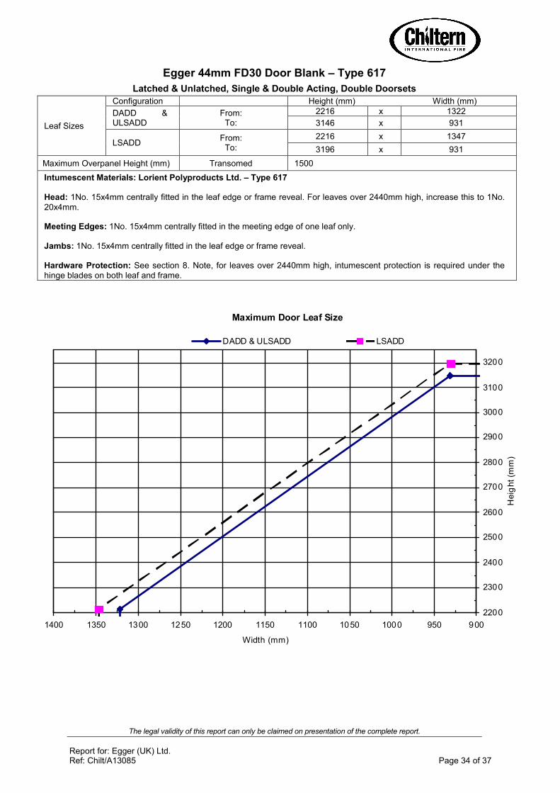
Egger 44mm FD30 Door Blank – Type 617
Latched & Unlatched, Single & Double Acting, Double Doorsets
Leaf Sizes
Configuration Height (mm) Width (mm)
DADD & ULSADD
From: To:
2216 x 1322
3146 x 931
LSADD From:
To:
2216 x 1347
3196 x 931
Maximum Overpanel Height (mm) Transomed 1500
Intumescent Materials: Lorient Polyproducts Ltd. – Type 617
Head: 1No. 15x4mm centrally fitted in the leaf edge or frame reveal. For leaves over 2440mm high, increase this to 1No.
20x4mm. Meeting Edges: 1No. 15x4mm centrally fitted in the meeting edge of one leaf only. Jambs: 1No. 15x4mm centrally fitted in the leaf edge or frame reveal. Hardware Protection: See section 8. Note, for leaves over 2440mm high, intumescent protection is required under the hinge blades on both leaf and frame.

The legal validity of this report can only be claimed on presentation of the complete report.
Report for: Egger (UK) Ltd. Ref: Chilt/A13085 Page 35 of 37
Maximum Door Leaf Size
2250
2300
2350
2400
2450
2500
9509751000102510501075
Width (mm)
He
igh
t (m
m)
DADD & ULSADD LSADD
Egger 44mm FD30 Door Blank – Pyroplex
Latched & Unlatched, Single & Double Acting, Double Doorsets
Leaf Sizes
Configuration Height (mm) Width (mm)
DADD & ULSADD
From: To:
2300 x 1025
2400 975
LSADD From:
To:
2300 x 1050
2450 x 975
Maximum Overpanel Height (mm) Transomed 1500
Intumescent Materials: Pyroplex Ltd. – Pyroplex Rigid Box Seals
Head: Square: 1No. 20x4mm centrally fitted in the leaf head or frame reveal.
Meeting Edges: 2No. 10x4mm spaced 12mm apart in the meeting edge of one leaf only. Jambs: 1No. 15x4mm centrally fitted in the leaf edge or frame reveal.
Hardware Protection: See section 8. Note, for leaves over 2440mm high, intumescent protection is required under the hinge blades on both leaf and frame.

The legal validity of this report can only be claimed on presentation of the complete report.
Report for: Egger (UK) Ltd. Ref: Chilt/A13085 Page 36 of 37
Maximum Door Leaf Size
2250
2300
2350
2400
95097510001025
Width (mm)
He
igh
t (m
m)
ULSADD+OP LSADD+OP
Egger 44mm FD30 Door Blank – Pyroplex
Latched & Unlatched, Single Acting, Double Doorsets + Overpanels
Leaf Sizes
Configuration Height (mm) Width (mm)
ULSADD+OP Max: 2300 x 975
LSADD+OP From:
To:
2300 x 1000
2350 x 975
Maximum Overpanel Height (mm) 1500
Intumescent Materials: Pyroplex Ltd. – Pyroplex Rigid Box Seals
Head: Square: 2No. 15x4mm spaced 7mm apart and centrally fitted in the bottom of the overpanel, or in the leaf head. Rebated: 2No. 15x4mm with one seal centrally fitted in the bottom of the leaf rebate and one seal in the opposite rebate. Meeting Edges: 2No. 10x4mm spaced 12mm apart in the meeting edge of one leaf only. Jambs: 1No. 15x4mm centrally fitted in the leaf edge or frame reveal.
Hardware Protection: See section 8.
The legal validity of this report can only be claimed on presentation of the complete report.
Report for: Egger (UK) Ltd. Ref: Chilt/A13085 Page 37 of 37
Maximum Door Leaf Size
2100
2200
2300
2400
2500
2600
2700
2800
900950100010501100115012001250
Width (mm)
He
igh
t (m
m)
ULSADD+OP LSADD+OP
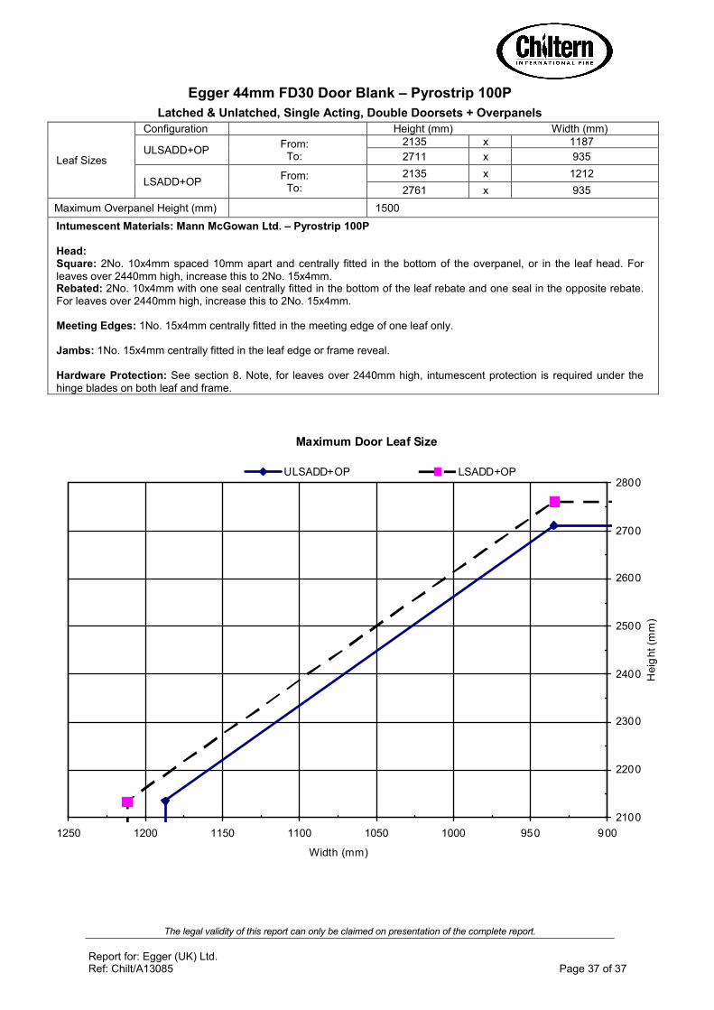
Egger 44mm FD30 Door Blank – Pyrostrip 100P
Latched & Unlatched, Single Acting, Double Doorsets + Overpanels
Leaf Sizes
Configuration Height (mm) Width (mm)
ULSADD+OP From:
To:
2135 x 1187
2711 x 935
LSADD+OP From:
To:
2135 x 1212
2761 x 935
Maximum Overpanel Height (mm) 1500
Intumescent Materials: Mann McGowan Ltd. – Pyrostrip 100P
Head: Square: 2No. 10x4mm spaced 10mm apart and centrally fitted in the bottom of the overpanel, or in the leaf head. For leaves over 2440mm high, increase this to 2No. 15x4mm. Rebated: 2No. 10x4mm with one seal centrally fitted in the bottom of the leaf rebate and one seal in the opposite rebate. For leaves over 2440mm high, increase this to 2No. 15x4mm. Meeting Edges: 1No. 15x4mm centrally fitted in the meeting edge of one leaf only. Jambs: 1No. 15x4mm centrally fitted in the leaf edge or frame reveal.
Hardware Protection: See section 8. Note, for leaves over 2440mm high, intumescent protection is required under the hinge blades on both leaf and frame.

EGGER (UK) Limited anick Grange Road Hexham, northumberland ne46 4Js united Kingdom t +44 1434 602191 f +44 1434 605103 [email protected]
www.egger.co.uk
FRITZ EGGER GmbH & Co. Holzwerkstoffe Weiberndorf 20 6380 st. Johann in tirol austria t +43 50 600-0 f +43 50 600-10111 [email protected]
en_1
9023
2_12
/10
subj
ect t
o te
chni
cal m
odifi
catio
ns a
nd a
men
dmen
ts. e
GG
eR re
serv
e th
e rig
ht to
am
end
the
rang
e at
any
tim
e.