test psi-bc / si-bc - gossenmetrawatt.com · 1 recording chart (psi module only) 2 ink cartridge...
TRANSCRIPT
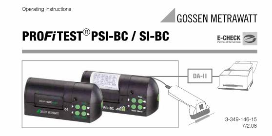
PROFiTEST®PSI-BC / SI-BC
3-349-146-157/2.08
Operating Instructions
DA-II
2 GMC-I Gossen-Metrawatt GmbH
MenuStore7
6
5
4
3
2
1
14
13
12
11
10
9
1516
8
GMC-I Gossen-Metrawatt GmbH 3
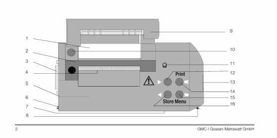
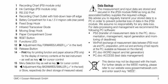
1 Recording Chart (PSI module only)2 Ink Cartridge (PSI module only)3 RS 232 Port4 Recording Chart Outlet with fold-down tear-off edge5 Battery Compartment for 4 ea.1.5 V mignon cells (rear panel)6 Fixed Snap Hook7 Infrared Transceiver Diode8 Moving Snap Hook9 Paper Compartment Cover
10 RESET Button11 Functions LED12 Adjustment Key FORWARDS/LARGER („>“ in the text)13 Release Button14 – Print Key for printing function and paper advance (PSI only)
for the display of memory contents at the test instrument – as well as key for cursor control
15 Menu Selection Key as well as key for cursor control16 Adjustment Key BACKWARDS/SMALLER („<“ in the text)
or Store, respectively (for direct storage of measured values)
Data BackupThe measurement and input data are stored and secured in the (P)SI module RAM as long as the
associated battery supplies the required voltage.We advise you to regularly transmit your stored data to a PC in order to prevent potential loss of data in the (P)SI module. We assume no responsibility for any data loss.For data processing and management we recommend the following PC software:• PS3 (transfer of measurement data to the PC, docu-
mentation, management, report generation and moni-toring of deadlines)
• WinProfi (exchange of measurement data between (P)SI mod-ule and PC, preparation, print-out and archiving of test reports at the PC; available as freeware on the internet)
• PC.doc-WORD (report and list generation)• PC.doc-ACCESS (test data management)
This device may not be disposed with the trash. For further details on the WEEE marking, please refer to our website www.gossenmetrawatt.com and enter search key ’WEEE’.
!
4 GMC-I Gossen-Metrawatt GmbH
Contents Page Contents Page
1 Applications ................................................ 6
2 Safety Features and Precautions ................ 6
3 Initial Start-Up ............................................. 73.1 Installing the Ink Cartridge (PSI module only) and the
Batteries ................................................................73.2 Attaching and Removing the (P)SI Module ................93.3 Resetting the (P)SI Module Functions .......................9
4 Operation .................................................. 104.1 Activating the (P)SI Module ....................................104.2 Storing Measured Values to Memory ......................114.2.1 Direct Storage of Measured Values ........................114.2.2 Activating Automatic Memory ................................124.2.3 Deactivating Automatic Memory .............................13
4.3 Selecting an Object, a Distribution Cabinet, an RCCB and an Electrical Circuit .......................... 14
4.3.1 Insulation Measurement Settings ........................... 154.3.2 Allocating Errors to the Corresponding Circuit ......... 164.3.3 Number of Circuits in the Distribution Cabinet ........ 174.4 Reviewing and Printing Stored Measured Values .... 184.4.1 Printing Measured Values for the Active Circuit ...... 184.4.2 Printing Measured Values for Stored Circuits
(PSI module only) ................................................. 194.4.3 Hard Copy Print-Out at the PSI Module .................. 214.4.4 Hard Copy Print-Out with External A4 Printer .......... 214.5 Displaying and Printing the List of
Stored Electrical Circuits (PSI module only) ............. 234.6 Deleting Stored Measured Values .......................... 244.7 Deleting the Entire Memory ................................... 26

GMC-I Gossen-Metrawatt GmbH 5
Contents Page Contents Page
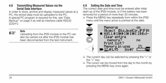
4.8 Transmitting Measured Values via the Serial Data Interface ..............................................28
4.9 Setting the Date and Time .....................................284.10 Error Message Assistance .....................................29
5 Using the B3261 Barcode Scanner ............325.1 Use ......................................................................325.2 Connecting (P)SI Module and Barcode Scanner .......325.3 Operation .............................................................325.4 Barcode Layout .....................................................335.5 Configuring the Barcode Scanner ...........................345.6 Sample Barcodes ..................................................35
6 Characteristic Values .................................36
7 Maintenance ..............................................377.1 Batteries ..............................................................37
7.2 Recording Chart Paper (PSI module only) ............... 387.2.1 Inserting the Recording Chart ................................ 387.3 Ink Cartridges ....................................................... 397.3.1 Replacing the Ink Cartridge (PSI module only) ......... 397.4 Housing ............................................................... 40
8 Appendix ................................................... 408.1 Abbreviations and their Meanings .......................... 40
9 Repair and Replacement Parts Service .... 41
10 Product Support ........................................ 41
6 GMC-I Gossen-Metrawatt GmbH
1 ApplicationsThe PSI (Printer Storage Interface) module PROFiTEST®PSI-BC is used as an output unit for the test instruments PROFiTEST®0100S, 0100S-I I as well as PROFiTEST® ONE and functions simultaneously as a printer, a memory and a data interface.Contrary to the PSI module, the SI module PROFiTEST®SI-BC does not have an internal printer.The (P)SI module can be directly attached and secured to the test instrument with two snap hooks.Values measured with the test instrument within an electri-cal circuit are transmitted directly to the (P)SI module with an infrared transceiver diode and stored there to memory. All measured values from a total of up to 200 electrical cir-cuits can be stored at the (P)SI module.PSI module: Measured values are printed out for each indi-vidual electrical circuit in the form of a measurement and test report including date and time of testing.(P)SI module: Stored measured values can be uploaded to a PC from the (P)SI module via the RS 232 port, and can be archived or printed out in a predefined report template with a special PC software, see “Data Backup” on page 3.
2 Safety Features and PrecautionsWhen used for its intended purpose, safety of the operator, as well as that of the instrument, is assured.An electrically conductive plastic has been used to manu-facture the housing and provide shielding in order to com-ply with legal requirements for electromagnetic compatibility (EMC). There is, however, no danger in touching the (P)SI module during normal operation, because the (P)SI module is fully isolated from the test instrument, and because no hazardous voltages occur within the (P)SI module.
Attention!Voltage conducting components may not be contacted with the housing of the (P)SI module, because the housing would otherwise become electrically charged. The housing of the (P)SI module demonstrates conductive, metal-like characteristics.
Read the operating instructions thoroughly and carefully before placing your instrument into service, and follow all instructions contained therein.
!
GMC-I Gossen-Metrawatt GmbH 7
3 Initial Start-Up3.1 Installing the Ink Cartridge (PSI module only) and
the BatteriesPSI module: Install the ink cartridge before initial start-up (see Replacing the Ink Cartridge (PSI module only), page 39). Four commercially available 1.5 V mignon cells in accor-dance with IEC LR6 are required for operation of the (P)SI module.
Attention!Only alkaline-manganese batteries should be used which are in compliance with the IEC LR6 standard. The (P)SI module does not function correctly if zinc-carbon batteries are used.
Rechargeable NiCd cells may also be used. However, they must be recharged with an external battery charger. Always replace the entire set of batteries. Dispose of depleted batteries in an environmentally sound fashion.
The battery compartment is located at the rear of the (P)SI module.➭ Open the battery compartment by pressing the retainer
to the side and removing the cover. Slightly tilting the (P)SI modules in a backwards direction causes the bat-tery holder to fall from the battery compartment, and can thus be easily removed.
➭ Place four 1.5 V alkaline-manganese mignon batteries into the battery holder poled correctly in the direction indicated by the symbols.
➭ Return the battery holder, along with the batteries, to the battery compartment.
➭ Return the battery compartment cover to the battery compartment and press lightly until it snaps into place.
PSI module: If battery voltage falls to a level below the acceptable value during printing or during paper advance, the printing sequence is interrupted.
!
8 GMC-I Gossen-Metrawatt GmbH
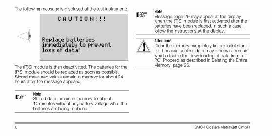
The following message is displayed at the test instrument:
The (P)SI module is then deactivated. The batteries for the (P)SI module should be replaced as soon as possible. Stored measured values remain in memory for about 24 hours after the message appears.
NoteStored data remain in memory for about 10 minutes without any battery voltage while the batteries are being replaced.
NoteMessage page 29 may appear at the display when the (P)SI module is first activated after the batteries have been replaced. In such a case, follow the instructions at the display.
Attention!Clear the memory completely before initial start-up, because useless data may otherwise remain which disable the downloading of data from a PC. Proceed as described in Deleting the Entire Memory, page 26.
☞
☞
!
GMC-I Gossen-Metrawatt GmbH 9
3.2 Attaching and Removing the (P)SI ModuleThe (P)SI module is secured to the swing-out control and display panel at the test instrument by means of snap hooks.
NoteIf the test instrument is operated while lying on its back, the support bar should be opened out before securing the (P)SI module to the control and dis-play panel at the test instrument.
➭ In order to attach the (P)SI module to the control and display panel, insert the fixed snap hook at the (P)SI module into the slot at the upper left of the test instru-ment, and press the (P)SI module until the moving snap hook audibly snaps into its holder (at the right).
➭ In order to remove the (P)SI module, lift it up and away to the right while holding the release button depressed.
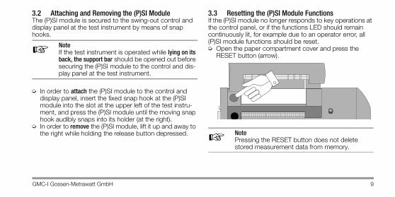
3.3 Resetting the (P)SI Module Functions If the (P)SI module no longer responds to key operations at the control panel, or if the functions LED should remain continuously lit, for example due to an operator error, all (P)SI module functions should be reset.➭ Open the paper compartment cover and press the
RESET button (arrow).
NotePressing the RESET button does not delete stored measurement data from memory.
☞
☞
10 GMC-I Gossen-Metrawatt GmbH
4 Operation4.1 Activating the (P)SI Module
Attention!Before activating the (P)SI module, the test instrument must first be activated by pressing the “Menu” key.
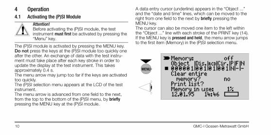
The (P)SI module is activated by pressing the MENU key.Do not press the keys at the (P)SI module too quickly one after the other. An exchange of data with the test instru-ment must take place after each key stroke in order to update the display at the test instrument. This takes approximately 0.4 s.The menu arrow may jump too far if the keys are activated too quickly.The (P)SI selection menu appears at the LCD of the test instrument.The menu arrow is advanced from one field to the next, from the top to the bottom of the (P)SI menu, by briefly pressing the MENU key at the (P)SI module.
A data entry cursor (underline) appears in the “Object ...” and the “date and time” lines, which can be moved to the right from one field to the next by briefly pressing the MENU key.The cursor can also be moved one item to the left within the “Object ...” line with each stroke of the PRINT key (14).If the MENU key is pressed and held, the menu arrow jumps to the first item (Memory) in the (P)SI selection menu.
!
MENU
GMC-I Gossen-Metrawatt GmbH 11
After 10 seconds – the red lamp goes outIf none of the keys at the (P)SI module are activated for a period of 10 s, the module is shut down automatically in order to extend battery service life. However, the display at the test instrument remains active.If any of the keys at the (P)SI module is pressed after these10 s have expired, the module is reactivated. The key must be pressed a second time in order to execute the corresponding function.
After 15 to 90 seconds 1) – the LCD is deactivatedIf none of the keys at the (P)SI module are activated for a period of 15 to 90 s, the test instrument is automatically shut down in order to extend battery service life.In order to reactivate the (P)SI module, one of the keys at the test instrument must first be pressed, and then one of the keys at the (P)SI module.
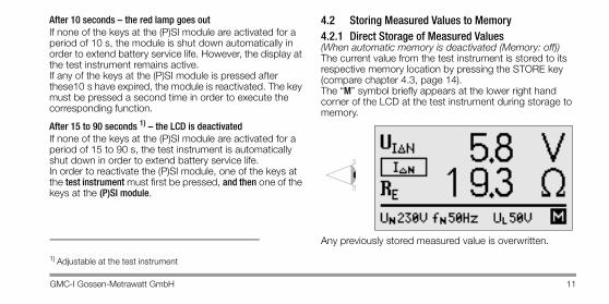
4.2 Storing Measured Values to Memory4.2.1 Direct Storage of Measured Values(When automatic memory is deactivated (Memory: off))The current value from the test instrument is stored to its respective memory location by pressing the STORE key (compare chapter 4.3, page 14).The “M” symbol briefly appears at the lower right hand corner of the LCD at the test instrument during storage to memory.
Any previously stored measured value is overwritten.
1) Adjustable at the test instrument
12 GMC-I Gossen-Metrawatt GmbH
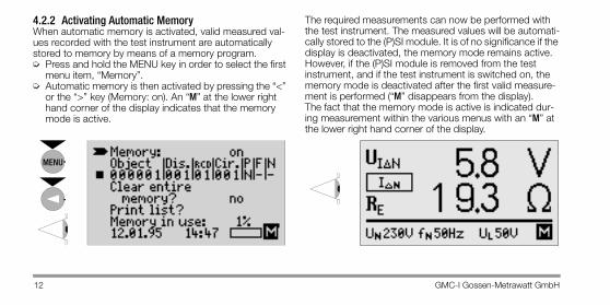
4.2.2 Activating Automatic MemoryWhen automatic memory is activated, valid measured val-ues recorded with the test instrument are automatically stored to memory by means of a memory program.➭ Press and hold the MENU key in order to select the first
menu item, “Memory”.➭ Automatic memory is then activated by pressing the “<”
or the “>” key (Memory: on). An “M” at the lower right hand corner of the display indicates that the memory mode is active.
The required measurements can now be performed with the test instrument. The measured values will be automati-cally stored to the (P)SI module. It is of no significance if the display is deactivated, the memory mode remains active. However, if the (P)SI module is removed from the test instrument, and if the test instrument is switched on, the memory mode is deactivated after the first valid measure-ment is performed (“M” disappears from the display).The fact that the memory mode is active is indicated dur-ing measurement within the various menus with an “M” at the lower right hand corner of the display.
MENU
GMC-I Gossen-Metrawatt GmbH 13
Only one valid measured value is stored for a given mea-sured quantity for the duration of measurement within a given electrical circuit. The storage program registers only the optimal value. The following are stored to memory:
1) The calculated UIΔN value is also stored at the RE memory location if no measurement of RE has been performed in the RE selector switch position. Measurements performed in the RE selector switch position take precedence and overwrite the corresponding value measured for UIΔN. The storage program cannot differentiate between measurements performed with or without a probe (loop).
2) The highest value is always stored for measurements within the UL-N range.Nominal voltages and frequencies are stored for the other ranges. The UL-N range takes precedence.
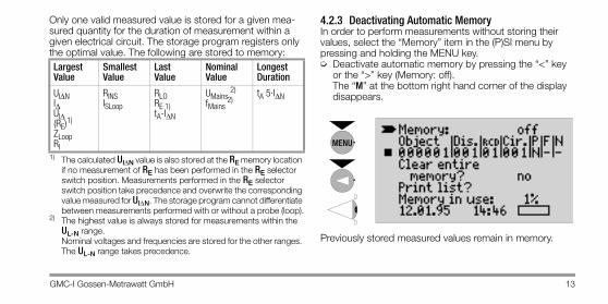
4.2.3 Deactivating Automatic MemoryIn order to perform measurements without storing their values, select the “Memory” item in the (P)SI menu by pressing and holding the MENU key.➭ Deactivate automatic memory by pressing the “<” key
or the “>” key (Memory: off).The “M” at the bottom right hand corner of the display disappears.
Previously stored measured values remain in memory.
Largest Value
Smallest Value
Last Value
Nominal Value
Longest Duration
UIΔNIΔUIΔ(RE)1)
ZLoopRI
RINSISLoop
RLORE 1)tA-IΔN
UMains 2)
fMains 2)
tA 5·IΔN
MENU
14 GMC-I Gossen-Metrawatt GmbH
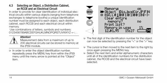
4.3 Selecting an Object, a Distribution Cabinet, an RCCB and an Electrical Circuit
In order to provide for clear identification of individual elec-trical circuits within various objects (ranging from telephone exchanges to telephone booths) a unique identification number must be assigned to each object, each distribution cabinet, each RCCB and each electrical circuit within memory. Use combinations of letters, symbols and numbers:0123456789ABCDEFGHIJKLMNOPQRSTUVWXYZ·+-:. .
Attention!Measurement data from a maximum of up to 200 electrical circuits can be stored to memory at the (P)SI module.
➭ In order to enter the object identification number, repeatedly press the MENU key from within the (P)SI menu until the menu arrow is pointed at the “Object” item.
➭ The first digit of the identification number for the object can now be selected by pressing the “<” or the “>” key.
➭ The cursor is then moved to the next item to the right by
once again pressing the MENU key.➭ Select the next item and enter alphanumeric characters
until all of the identification numbers for the distribution cabinet, the RCCB and the electrical circuit have been selected.
!
MENU

GMC-I Gossen-Metrawatt GmbH 15
Attention!Circuits for which data have already been recorded are identified with a solid square ( ) in the identification number line within the (P)SI menu.Circuits for which data have not yet been recorded are represented with an empty square ( ) in the identification number line.
4.3.1 Insulation Measurement SettingsTwo measured values per electrical circuit can be recorded for insulation measurements.➭ Move the cursor to position P by pressing the MENU
key.➭ Select Phase L or N, with or without load (L), by press-
ing the “<” or the “>” key.➭ Continue to the next menu item with the MENU key.
!
16 GMC-I Gossen-Metrawatt GmbH
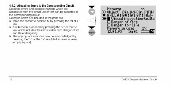
4.3.2 Allocating Errors to the Corresponding CircuitDetected errors and possible hazards which are associated with the circuit under test can be allocated to the corresponding circuit. Detected errors are included in the print-out.➭ Move the cursor to position M by pressing the MENU
key.➭ A sub-menu is opened by pressing the “<” or the “>”
key which includes the items visible flaw, danger of fire and life endangering.
➭ The appropriate error can now be acknowledged by pressing the “<” or the “>” key (filled square), or reset (empty square).
MENU
GMC-I Gossen-Metrawatt GmbH 17
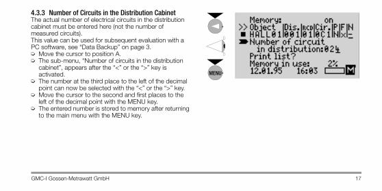
4.3.3 Number of Circuits in the Distribution CabinetThe actual number of electrical circuits in the distribution cabinet must be entered here (not the number of measured circuits).This value can be used for subsequent evaluation with a PC software, see “Data Backup” on page 3.➭ Move the cursor to position A.➭ The sub-menu, “Number of circuits in the distribution
cabinet”, appears after the “<” or the “>” key is activated.
➭ The number at the third place to the left of the decimal point can now be selected with the “<” or the “>” key.
➭ Move the cursor to the second and first places to the left of the decimal point with the MENU key.
➭ The entered number is stored to memory after returning to the main menu with the MENU key.
MENU
18 GMC-I Gossen-Metrawatt GmbH
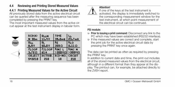
4.4 Reviewing and Printing Stored Measured Values4.4.1 Printing Measured Values for the Active CircuitAll previously stored data from the active electrical circuit can be queried after the measuring sequence has been completed by pressing the PRINT key.The most important measured values from the active cir-cuit appear at the test instrument display in tabular form.
Attention!If one of the keys at the test instrument is activated, the display is immediately switched to the corresponding measurement window for the test instrument, at which point measurement of the electrical circuit can be continued.
PSI module:➭ Prior to issuing a print command: Disconnect any link to the
PC which may have been established (RS232 interface).➭ If the measured values are correct and complete, start
the print job for the active electrical circuit data by pressing the PRINT key once again.
The data can be printed as often as required by pressing the PRINT key.In addition to current date and time, the print-out includes all of the stored measured values from the electrical circuit, although in a different format than they appear at the dis-play. The printout can, for example, be attached directly to the ZVEH report.
!
GMC-I Gossen-Metrawatt GmbH 19
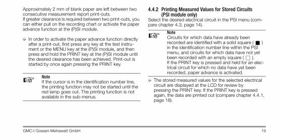
Approximately 2 mm of blank paper are left between two consecutive measurement report print-outs.If greater clearance is required between two print-outs, you can either pull on the recording chart or activate the paper advance function at the (P)SI module.
➭ In order to activate the paper advance function directly after a print-out, first press any key at the test instru-ment or the MENU key at the (P)SI module, and then press and hold the PRINT key at the (P)SI module until the desired clearance has been achieved. Print-out is started by once again pressing the PRINT key.
NoteIf the cursor is in the identification number line, the printing function may not be started until the red lamp goes out. The printing function is not available in the sub-menus.
4.4.2 Printing Measured Values for Stored Circuits (PSI module only)
Select the desired electrical circuit in the PSI menu (com-pare chapter 4.3, page 14).
NoteCircuits for which data have already been recorded are identified with a solid square ( ) in the identification number line within the PSI menu, and circuits for which data have not yet been recorded with an empty square ( ). If the PRINT key is pressed and held for an elec-trical circuit for which no data have yet been recorded, paper advance is activated.
➭ The stored measured values for the selected electrical circuit are displayed at the LCD for review by pressing the PRINT key. If the PRINT key is pressed again, the data are printed out (compare chapter 4.4.1, page 18).
☞
☞
20 GMC-I Gossen-Metrawatt GmbH
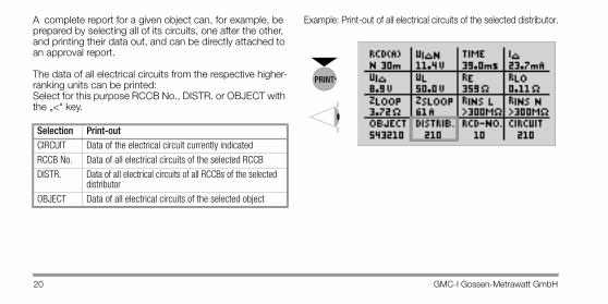
A complete report for a given object can, for example, be prepared by selecting all of its circuits, one after the other, and printing their data out, and can be directly attached to an approval report.
The data of all electrical circuits from the respective higher-ranking units can be printed:Select for this purpose RCCB No., DISTR. or OBJECT with the „<“ key.
Example: Print-out of all electrical circuits of the selected distributor.
Selection Print-outCIRCUIT Data of the electrical circuit currently indicated
RCCB No. Data of all electrical circuits of the selected RCCB
DISTR. Data of all electrical circuits of all RCCBs of the selected distributor
OBJECT Data of all electrical circuits of the selected object
GMC-I Gossen-Metrawatt GmbH 21
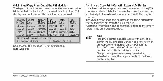
4.4.3 Hard Copy Print-Out at the PSI ModuleThe layout of the lines and columns for the measured value table printed out by the PSI module differs from the LCD display, and includes additional information as well.
See chapter 8.1 on page 40 for definitions of abbreviations.
4.4.4 Hard Copy Print-Out with External A4 PrinterIf the DA-I I printer adapter has been connected to the (P)SI module, all stored data for the selected object are read out exclusively to the external printer when the PRINT key is pressed.The layout of the lines and columns in the table differs from that of the print-out from the (P)SI module.Additional information can be manually added to the empty fields in the print-out if required.
NoteThe DA-II printer adapter works with almost all commercially available Centronics printers which are capable of understanding ASCII format. Pure “Windows printers” do not work in combination with the printer adapter. The printer’s parameters may have to be adjusted to meet the requirements of the DA-II printer adapter.
☞
22 GMC-I Gossen-Metrawatt GmbH
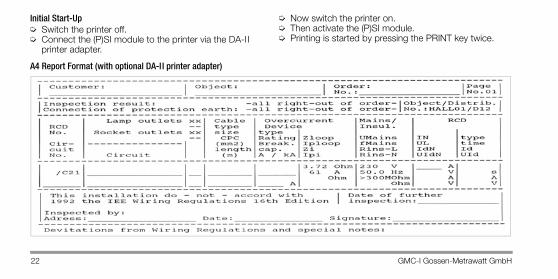
Initial Start-Up➭ Switch the printer off.➭ Connect the (P)SI module to the printer via the DA-I I
printer adapter.
➭ Now switch the printer on.➭ Then activate the (P)SI module.➭ Printing is started by pressing the PRINT key twice.
A4 Report Format (with optional DA-I I printer adapter)
GMC-I Gossen-Metrawatt GmbH 23
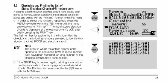
4.5 Displaying and Printing the List of Stored Electrical Circuits (PSI module only)
In order to determine which electrical circuits have already been stored to memory, a brief overview of these circuits can be dis-played and printed with the “Print list?” function in the (P)SI menu.➭ In order to select this function, repeatedly press the
MENU key from within the (P)SI menu until the menu arrow points to “Print list?”. The list of stored electrical circuits is displayed at the test instrument’s LCD after briefly pressing the PRINT key.
The first number for each entry in the list identifies the object, and the following numbers are used to identify dis-tribution cabinet, RCCB and electrical circuit.
NoteThe order in which the entries appear corre-sponds to the sequence in which measurement data have been recorded, as long as none of the electrical circuits have been deleted.
➭ If the PRINT key is pressed again, printing is started, or the display scrolls to the next page of stored electrical circuits. The Display can be returned to the (P)SI menu with the MENU key.
MENU
24 GMC-I Gossen-Metrawatt GmbH
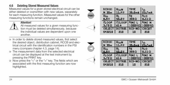
4.6 Deleting Stored Measured ValuesMeasured values for a given stored electrical circuit can be either deleted or overwritten with new values, separately for each measuring function. Measured values for the other measuring functions remain unchanged.
Attention!All measured values for a given measuring func-tion must be deleted simultaneously, because the individual values are dependent upon one another.
➭ In order to delete stored measured values, first select the desired object, distribution cabinet, RCCB and elec-trical circuit with the identification numbers in the PSI menu (compare chapter 4.3, page 14).
➭ The measurement data from the selected electrical circuit can be displayed at the test instrument by pressing the PRINT key.
➭ Now press the “<” or the “>” key. The fields which are associated with the first measuring function are now highlighted.

GMC-I Gossen-Metrawatt GmbH 25
➭ The field within the measuring function which needs to be deleted can now be selected by pressing the “<” or the “>” again.
➭ Acknowledge deletion of the stored measurement data by simultaneously pressing the “<” and the “>” keys. All measured values for the selected measuring function have now been deleted.
The corresponding measurement data can be recorded again, after the appropriate measuring function has been selected with the meas. range switch at the test instrument.
NoteIf you want to delete measured values for several measurement functions at the same time, select the appropriate measuring functions one after the other with the “<” or the “>” key, and delete the stored data by simultaneously pressing the “<” and the “>” keys.
☞
26 GMC-I Gossen-Metrawatt GmbH
Attention! If the CIRCUIT field has been selected for deletion, all measurement data for the corresponding elec-trical circuit are deleted. The other circuits remain unchanged. If the RCCB NO. field has been selected for dele-tion, all circuits for the selected RCCB are deleted. The circuits for all other RCCBs remain unaffected.If the DISTR. field has been selected for deletion, all electrical circuits from the selected distribution cabinet are deleted. The circuits for all other dis-tribution cabinets remain unaffected.If the OBJECT field has been selected for deletion, all circuits within the selected object are deleted. The circuits from all other objects remain unaf-fected. Additional space for new measurements can thus be quickly created, without deleting the entire memory.
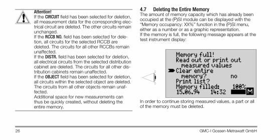
4.7 Deleting the Entire MemoryThe amount of memory capacity which has already been occupied at the (P)SI module can be displayed with the “Memory occupancy: XX%” function in the (P)SI menu, either as a number or as a graphic representation. If the memory is full, the following message appears at the test instrument display:
In order to continue storing measured values, a part or all of the memory must be deleted.
!
GMC-I Gossen-Metrawatt GmbH 27
Attention!Print all stored measured values out before dele-tion if they might be needed again in the future, or upload and store them to a PC (compare chapter 4.8, page 28).
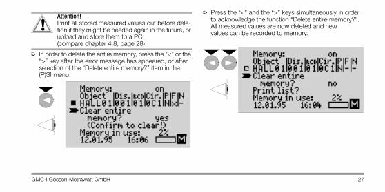
➭ In order to delete the entire memory, press the “<” or the “>” key after the error message has appeared, or after selection of the “Delete entire memory?” item in the (P)SI menu.
➭ Press the “<” and the “>” keys simultaneously in order to acknowledge the function “Delete entire memory?”.All measured values are now deleted and new values can be recorded to memory.
!
28 GMC-I Gossen-Metrawatt GmbH
4.8 Transmitting Measured Values via the Serial Data Interface
In order to store, archive and display measured values at a PC, the stored data must be uploaded to the PC. A special PC program is required for this, see “Data Backup” on page 3 as well as interface cable RS232 (Z3241).
NoteUploading from the (P)SI module to the PC can also be carried out after the (P)SI module has been disconnected from the test instrument.
4.9 Setting the Date and Time The correct date and time must be entered after initial start-up of the (P)SI module, or if the battery has been removed for a period of more than 30 minutes.➭ Press the MENU key repeatedly from within the (P)SI
menu until the menu arrow is pointed at the date.
➭ The current day can be selected by pressing the “<” or the “>” key.
➭ The cursor can be moved from the day to the month by pressing the MENU key once again.
☞MENU
GMC-I Gossen-Metrawatt GmbH 29
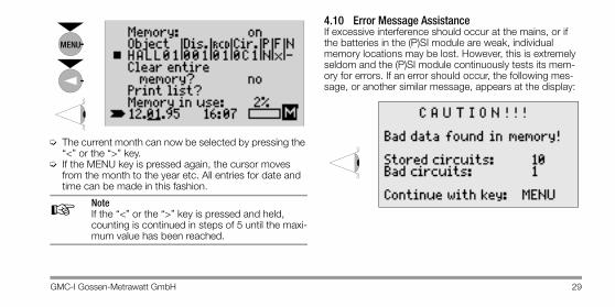
➭ The current month can now be selected by pressing the “<” or the “>” key.
➭ If the MENU key is pressed again, the cursor moves from the month to the year etc. All entries for date and time can be made in this fashion.
NoteIf the “<” or the “>” key is pressed and held, counting is continued in steps of 5 until the maxi-mum value has been reached.
4.10 Error Message AssistanceIf excessive interference should occur at the mains, or if the batteries in the (P)SI module are weak, individual memory locations may be lost. However, this is extremely seldom and the (P)SI module continuously tests its mem-ory for errors. If an error should occur, the following mes-sage, or another similar message, appears at the display:
MENU
☞

30 GMC-I Gossen-Metrawatt GmbH
➭ One of the following menu items can be selected after pressing the MENU key.
➭ An overview of circuits with defective data is displayed by pressing the PRINT key. PSI module: The list can be printed out by pressing the PRINT key again.
➭ The error message can be ignored by pressing the MENU key without deleting any data.
Tip Always print out the list of defective circuits first with the PRINT function, before ignoring the error message with the MENU key. (SI module: please take note of this list, if necessary)The questionable circuits can be tested for possible problems with the printed list (compare chapter 4.4, page 18).If an error has occurred in the assignment of an object or an electrical circuit, all electrical circuits from the affected object are copied to object 999, and the individual circuits are numbered consecutively starting with 0. The individual electrical circuits can be checked in object 999 for possible errors.Incorrect symbols appear as a “–” at the LCD and are printed as an “X”.
☞

GMC-I Gossen-Metrawatt GmbH 31
➭ If you are not certain that the measured values are cor-rect, delete the defective circuit by simultaneously pressing the “<” and the “>” keys. The following message then appears:
32 GMC-I Gossen-Metrawatt GmbH
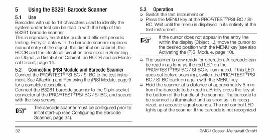
5 Using the B3261 Barcode Scanner5.1 UseBarcodes with up to 14 characters used to identify the system under test can be read in with the help of the B3261 barcode scanner.This is especially helpful for quick and efficient periodic testing. Entry of data with the barcode scanner replaces manual entry of the object, the distribution cabinet, the RCCB and the electrical circuit as described in Selecting an Object, a Distribution Cabinet, an RCCB and an Electri-cal Circuit, page 14.
5.2 Connecting (P)SI Module and Barcode ScannerConnect the PROFiTEST®PSI-BC / SI-BC to the test instru-ment. See Attaching and Removing the (P)SI Module, page 9 for a complete description.Connect the B3261 barcode scanner to the 9-pin socket connector at the PROFiTEST®PSI-BC / SI-BC, and secure with the two screws.
The barcode scanner must be configured prior to initial start-up (see Configuring the Barcode Scanner, page 34).
5.3 Operation➭ Switch the test instrument on.➭ Press the MENU key at the PROFiTEST®PSI-BC / SI-
BC. Wait until the menu is displayed in its entirety at the test instrument.
If the cursor does not appear in the entry line within the display (Object ...), move the cursor to the desired position with the MENU key (see also Activating the (P)SI Module, page 10).
➭ The scanner is now ready for operation. A barcode can be read in as long as the red LED on the PROFiTEST®PSI-BC / SI-BC is illuminated. If this LED goes out before scanning, switch the PROFiTEST®PSI-BC / SI-BC back on again with the MENU key.
➭ Hold the scanner at a distance of approximately 5 mm from the barcode to be read in. Briefly press the key at the bottom of the handle at the scanner. The barcode to be scanned is illuminated and as soon as it is recog-nized, an acoustic signal sounds. The red control LED lights up at the scanner. If the barcode is not recognized ☞
☞
GMC-I Gossen-Metrawatt GmbH 33
after the first attempt, change the distance and positioning of the scanner and activate the scan key once again.
➭ The system description is then transmitted from the scanner to the PROFiTEST®PSI-BC / SI-BC. After approximately 1 to 2 seconds, the data appear at the display of the test instrument. The red LED at the PROFiTEST®PSI-BC / SI-BC goes out immediately after the code has been transmitted. Electrical circuit settings are now complete.
➭ Testing of the electrical circuit may now begin.➭ In order to save measured values to the
PROFiTEST®PSI-BC / SI-BC, refer to chapter 4.2 and subsequent sections.
5.4 Barcode LayoutA suitable barcode consists of 4 categories and is laid out as follows:Building description (6 characters)Distribution cabinet entries (3 characters)RCCB entries (2 characters)Electrical circuit entries (3 characters)
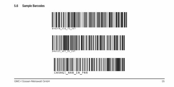
All characters must always be used. Do not use any blanks in the barcode, because the number cannot otherwise be correctly read in by the PC programs. Underlines (_) can be used for better legibility. Use characters and numbers only. Periods (.), colons (:) and commas (,) can also be used. Other characters may not be used.The so-called CODE128 system is used as barcode. Other common barcode systems may not be used.Barcodes used for configuring the scanner, as well as several sample barcodes for test purposes, are included below.

34 GMC-I Gossen-Metrawatt GmbH
5.5 Configuring the Barcode ScannerThe B3261 barcode scanner must be configured prior to initial start-up before it can be used with the PROFiTEST®PSI-BC / SI-BC. Proceed as follows:
➭ Connect the barcode scanner to the PROFiTEST®PSI-BC / SI-BC.
➭ Switch the test instrument on.➭ Press the MENU key at the (P)SI module.➭ Scan the following two barcodes, one after the other.
If you want to use the B3261 barcode scanner in combination with another device, the following configuration must be scanned in. This cancels the special configuration from the previous step.
GMC-I Gossen-Metrawatt GmbH 35
5.6 Sample Barcodes

36 GMC-I Gossen-Metrawatt GmbH
6 Characteristic ValuesConnectorsFor Fastening to theTest Instrument 2 snap hooks
for direct mountingto the test instrumentDirect measurement data transmission via bidirectional infrared interface
Interface RS 232, 9-pole socket
MemoryRAM (data) 32 kByte
Printer (PSI module only)Printing Mechanism 4-needle matrix printerPrint Width 40 characters per lineReal-Time Clock with Date Integrated battery backup
Data InterfaceType RS 232 serial port per
DIN 19241Baud Rate 9600 baudParity NoneData Bits 8Stop Bits 1
Interface Connector Pin AssignmentsThe 9-pole connector socket for the serial interface is connected as follows:
1: NC2: TxD (display (P)SI)3: RxD (display (P)SI)4: NC 5: GND6: +5V7: NC 8: Reset9: NC 9 8 7 6
5 4 3 2 1
RxD TxD
GND+5VReset
GMC-I Gossen-Metrawatt GmbH 37
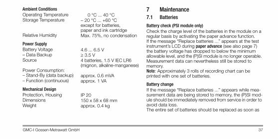
Ambient ConditionsOperating Temperature 0 °C ... 40 °CStorage Temperature − 20 °C ... +60 °C
except for batteries, paper and ink cartridge
Relative Humidity Max. 75%, no condensation
Power SupplyBattery Voltage 4.6 ... 6.5 V– Data Backup ≥ 3.5 VSource 4 batteries, 1.5 V IEC LR6
(mignon, alkaline-manganese)Power Consumption:– Stand-By (data backup) approx. 0.6 mVA– Function (continuous) approx. 1 VA
Mechanical DesignProtection, Housing IP 20Dimensions 150 x 58 x 68 mmWeight approx. 0.4 kg
7 Maintenance7.1 Batteries
Battery check (PSI module only)Check the charge level of the batteries in the module on a regular basis by activating the paper advance function.If the message “Replace batteries ...” appears at the test instrument’s LCD during paper advance (see also page 7) the battery voltage has dropped to below the minimum allowable level, and the (P)SI module is no longer operable. Measurement data can nevertheless still be stored to memory. Note: Approximately 3 rolls of recording chart can be printed with one set of batteries.
Battery changeIf the message “Replace batteries ...” appears while mea-surement data are being stored to memory, the (P)SI mod-ule should be immediately removed from service in order to avoid data loss.The entire set of batteries should be replaced as soon as
38 GMC-I Gossen-Metrawatt GmbH
possible (compare chapter 3.1, page 7).Stored measured values remain in memory for approximately 1 day.
AttentionDead batteries may not be left inside the module. Dispose of depleted batteries in an environmen-tally sound fashion.
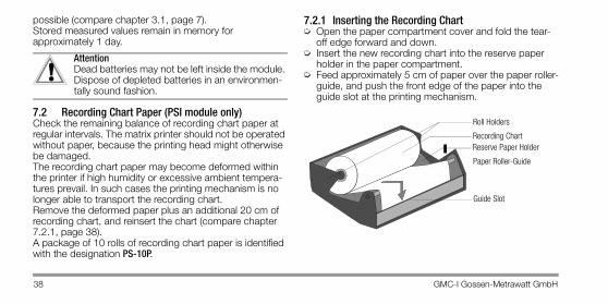
7.2 Recording Chart Paper (PSI module only)Check the remaining balance of recording chart paper at regular intervals. The matrix printer should not be operated without paper, because the printing head might otherwise be damaged.The recording chart paper may become deformed within the printer if high humidity or excessive ambient tempera-tures prevail. In such cases the printing mechanism is no longer able to transport the recording chart. Remove the deformed paper plus an additional 20 cm of recording chart, and reinsert the chart (compare chapter 7.2.1, page 38).A package of 10 rolls of recording chart paper is identified with the designation PS-10P.
7.2.1 Inserting the Recording Chart➭ Open the paper compartment cover and fold the tear-
off edge forward and down.➭ Insert the new recording chart into the reserve paper
holder in the paper compartment. ➭ Feed approximately 5 cm of paper over the paper roller-
guide, and push the front edge of the paper into the guide slot at the printing mechanism.
!
Paper Roller-Guide
Guide Slot
Reserve Paper HolderRecording Chart
Roll Holders

GMC-I Gossen-Metrawatt GmbH 39
➭ Press and hold the PRINT key for about 4 seconds in order to activate paper advance, and the paper is auto-matically fed through the printing mechanism. Hold the PRINT key depressed until the front edge of the paper appears at the discharge slot.
➭ Clinch the paper roll between the two roll holders in the paper compartment.
➭ Return the tear-off edge to its original position and press the paper compartment cover closed, until it audibly snaps into place.
7.3 Ink CartridgesIf the print-out becomes overly faded, the ink cartridge should be replaced (compare chapter 7.3.1, page 39).
NoteA package of 10 ink ribbon cartridges is identified with the designation Z3210. Approximately 6 rolls of recording chart can be printed with one ink cartridge.
7.3.1 Replacing the Ink Cartridge (PSI module only)➭ Open the paper compartment cover and fold the tear-
off edge forward and down.➭ In order to remove the cartridge, press on it gently at the
right hand side. The cartridge is tilted away from the holder. Carefully remove the ink cartridge.
MenuStore
40 GMC-I Gossen-Metrawatt GmbH
➭ Insert the new ink ribbon cartridge, with the ribbon ten-sioning screw pointing to the left, into the slot provided for this purpose. Press lightly at the right hand side of the cartridge until it snaps into its holder.
If recording chart paper has already been installed, it must be fed between the ink ribbon and the cartridge before the ink cartridge is inserted into the slot.The ink ribbon must be flat, and must be situated under-neath the recording chart when the cartridge is inserted into the slot. The tension at the ink ribbon can be adjusted by turning the ribbon tensioning screw.
7.4 HousingNo special maintenance is required for the housing. Keep outside surfaces clean. Use a slightly dampened cloth for cleaning. Avoid the use of cleansers, abrasives or solvents.
8 Appendix8.1 Abbreviations and their MeaningsFI (A) Nominal fault current IΔN (N = normal, S = selective)
UIΔN Contact voltage with reference to nominal fault current IΔN
tA Release time
IΔ Tripping current
UIΔ Contact voltage at the moment of tripping
UL Contact voltage limit value
ZLoop Loop Impedance
ISLOOPCalculated short-circuit current during loop impedancemeasurement
RINS LInsulation resistance, measured with phase = L
RINS NInsulation resistance, measured with phase = N
RLO Resistance at bonding conductors
RE Measured earth resistance
ZST Standing surface insulation resistance
UMainsLine voltage
GMC-I Gossen-Metrawatt GmbH 41
9 Repair and Replacement Parts ServiceIf required please contact:
GMC-I Gossen-Metrawatt GmbHService-CenterThomas-Mann-Strasse 2090471 Nürnberg • Germany Phone +49 911 8602-0Fax +49 911 8602-253E-Mail [email protected]
This address is only valid in Germany. Please contact our representatives or subsidiaries for service in other coun-tries.
10 Product SupportIf required please contact:
GMC-I Gossen-Metrawatt GmbHProduct Support Hotline Phone +49 911 8602-0Fax +49 911 8602-709E-Mail [email protected]
Edited in Germany • Subject to change without notice • pdf version is available on the internet
GMC-I Gossen-Metrawatt GmbHThomas-Mann-Str. 16-2090471 Nürnberg • Germany
Phone +49 911 8602-111Fax +49 911 8602-777E-Mail [email protected]