test procedure for measurement of … emf measurement.pdf · – icinrp guidelines for limiting...
TRANSCRIPT

Division: Radio
Issue: June 2018
TEST PROCEDURE
FOR MEASUREMENT OF
ELECTROMAGNETIC FIELDS
FROM
BASE STATION ANTENNA
No: TEC/TP/EMF/001/04.JUN 2018
(Supersedes document No: TEC/TP/EMF/001/02.OCT 2012 and other related addendums)
© TEC
TELECOMMUNICATION ENGINEERING CENTRE
KHURSHID LAL BHAVAN, JANPATH
NEW DELHI-110001
INDIA
All rights reserved and no part of this publication may be reproduced, stored in a retrieval system or transmitted, in any
form or by any means, electronic, mechanical, photocopying, recording, scanning or otherwise without written permission
from the Telecommunication Engineering Centre New Delhi.

No: TEC/TP/EMF/001/04.JUN 2018
2
Contents
History Sheet.......................................................................................................... 5
1.0 Scope ................................................................................................................................... 6
1.1 References ....................................................................................................................... 7
2.0 EMF exposure zones. .......................................................................................................... 7
3.0 Exposure level assessment .................................................................................................. 8
4.0 The installation classification scheme ................................................................................. 9
5.0 Procedure for determining installation class ....................................................................... 9
6.0 EMF evaluation techniques ............................................................................................... 11
7.0 Prediction of R.F. fields..................................................................................................... 13
7.1 Equations for predicting RF fields................................................................................. 13
7.2 Field regions .................................................................................................................. 14
8.0 Determination of EIRPth ................................................................................................. 15
8.1 Accessibility categories ................................................................................................. 16
8.2 Antenna directivity categories ....................................................................................... 19
8.3 The exclusion area ......................................................................................................... 21
9.0 Compliance options available to service providers for submission of self ertification ..... 22
10.0 Field Measurement Approach. ......................................................................................... 24
10.1 Test Instruments Required ............................................................................................. 25
10.2 Calibration of instruments ............................................................................................. 26
11.0 Responsibility of Service Providers at Shared Sites .......................................................... 26
12.0 Numbering Scheme for Base Station and its Self-Certificates .......................................... 27
13.0 Compliance by calculations of EIRP/EIRPth based on ITU-T Recommendation K.52 .... 31
14.0 Compliance by Simplified Assessment Procedure Criteria based on ITU-T
Recommendation K.100 ................................................................................................................ 36

No: TEC/TP/EMF/001/04.JUN 2018
3
15.0 Compliance by Software Simulation ................................................................................. 37
16.0 Compliance by Measurements .......................................................................................... 39
16.1 Measurement Spots and Time ................................................................................... 40
16.2 DoT Limits for Compliance when using Broadband Instruments ............................. 40
17.0 Compliance by Broadband Measurements ........................................................................ 40
18.0 Compliance by Frequency Selective Measurements. ........................................................ 41
19.0 Safety Signage ................................................................................................................... 42
20.0 LSA Cell Audit ................................................................................................................... 43
21.0 EMF Portal: ....................................................................................................................... 43
22.0 Conclusion ......................................................................................................................... 43
Appendix – A ................................................................................................................................ 44
EXAMPLE OF EIRPth CALCULATION ..................................................................................... 44
Appendix-B ................................................................................................................................... 51
FORMAT FOR CERTIFICATION OF BASE STATION FOR COMPLIANCE OF THE EMF
EXPOSURE LEVELS (CALCULATION OF EIRP/EIRPth) ...................................................... 51
Appendix-C .......................................................................................................................................
FORMAT FOR CERTIFICATION OF BASE STATION FOR COMPLIANCE OF THE EMF
EXPOSURE LEVELS (BROADBAND MEASUREMENT) ...................................................... 55
Appendix –D ................................................................................................................................. 58
FORMAT FOR CERTIFICATION OF BASE STATION FOR COMPLIANCE OF THE EMF
EXPOSURE LEVELS (SOFTWARE SIMULATION) ................................................................ 58
Appendix –E .................................................................................................................................. 62
FORMAT FOR FREQUENCY SELECTIVE MEASUREMENT FOR CERTIFICATION OF
BASE STATION FOR COMPLIANCE WITH THE SAFE LIMITS FOR EMF EXPOSURE
FROM CELLULAR RADIO BASE STATIONS ......................................................................... 62
Appendix –F .................................................................................................................................. 75

No: TEC/TP/EMF/001/04.JUN 2018
4
FORMAT FOR SIMPLIFIED ASSESSMENT PROCEDURE FOR SELF CERTIFICATION AS
PER ITU-T RECOMMENDATION K.100 .................................................................................. 75
Appendix- G .................................................................................................................................. 79
FORMAT FOR MONTHLY SUMMARY REPORT OF COMPLIANCE FOR TSP XXX (LSA)
SITES - DUE TO UPGRADES/ ADDITIONS BY OTHER TSPs ..................................................
TERMS AND DEFINITIONS ...................................................................................................... 79

No: TEC/TP/EMF/001/04.JUN 2018
5
HISTORY SHEET
Name of Document/ title Document No. Status
Test Procedure for Measurement of
Electromagnetic Field Strength from
Base station Antennas
TEC/TP/EMF/001/01.SEP2012 Superseded
Test Procedure for Measurement of
Electromagnetic Field Strength from
Base station Antennas
TEC/TP/EMF/001/02.OCT 2012 Superseded
Amendment-1 dated 26-12-2012
Addendum-2 dated 21-04-2015
Amendment-3 and its revision 01 on
Frequency Selective Measurement of
EMF
Amendment-4 and its revision 01 on
Simplified Assessment Procedure for
EMF compliance of Low Power BTS
Test Procedure for Measurement of
Electromagnetic Field Strength from
Base station Antennas
TEC/TP/EMF/001/04.JUN 2018 In force
No: TEC/TP/EMF/001/04.JUN 2018
6
TEST PROCEDURE FOR MEASUREMENT OF ELECTROMAGNETIC
FIELDS FROM BASE STATION ANTENNA
1.0 Scope
This document provides the detailed procedure for the certificate of compliance of EMF
exposure norms by the Telecom Service Providers (TSPs) and audit by the Licensed
Service Area (LSA) Units of the Department of Telecommunications (DOT).
The objective of this Test Procedure is to confirm the EMF exposure from base station
installations as per the exposure limits prescribed by the DOT.
The Telecom Service Providers will establish necessary facility for self-testing and
offering them for auditing of EMF measurement to the concerned LSA Unit for
complying with emission limits as per limits prescribed by the Department of
Telecommunications vide Memo No. 800-15/2010-VAS (Pt), dated 30.12.2011
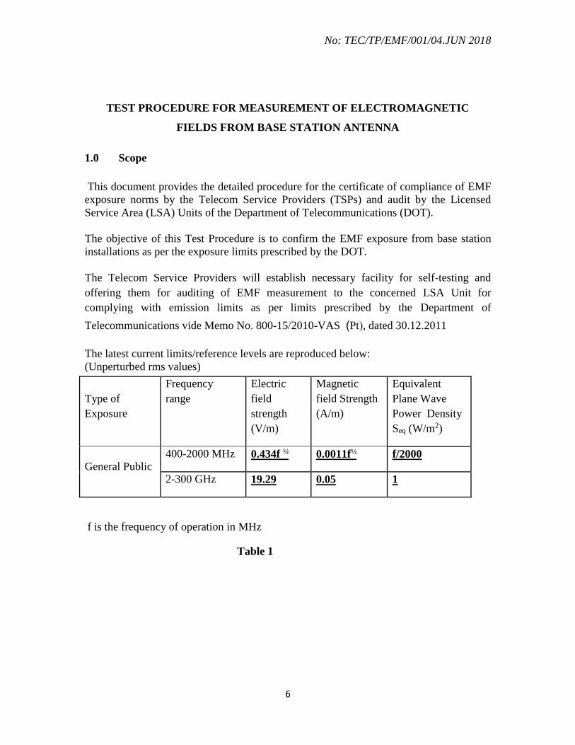
The latest current limits/reference levels are reproduced below:
(Unperturbed rms values)
f is the frequency of operation in MHz
Table 1
Type of
Exposure
Frequency
range
Electric
field
strength
(V/m)
Magnetic
field Strength
(A/m)
Equivalent
Plane Wave
Power Density
Seq (W/m2)
General Public 400-2000 MHz 0.434f ½ 0.0011f½ f/2000
2-300 GHz 19.29 0.05 1

No: TEC/TP/EMF/001/04.JUN 2018
7
1.1 References
The following ITU-T Recommendations:
ITU-T Recommendation K.52 (212/2016), Guidance on complying with limits for
human exposure to electromagnetic fields.
ITU-T Recommendation K.61 (2003), Guidance to measurement and numerical
prediction of electromagnetic fields for compliance with human exposure limits
for telecommunication installations.
K.70 (2007): “Mitigation techniques to limit human exposure to EMFs in the
vicinity of radiocommunication stations”
– K.100 (2014): “Measurement of radio frequency electromagnetic fields to
determine compliance with human exposure limits when a base station is put into
service”
– IEC 62232 (2011): Determination of RF field strength and SAR in the vicinity of
radiocommunication base stations for the purpose of evaluating human exposure.
– ICINRP Guidelines for limiting exposure to time- varying Electric, magnetic and
electromagnetic fields (upto 300 GHz)
– EN 50492:2008 & A1 (2014): Basic standard for in-situ measurement of
electromagnetic field strength related to human exposure in the vicinity of base
stations.
– IEC TR/62669: Case studies supporting IEC 62232.
2.0 EMF exposure zones.
2.1 EMF exposure assessment is made if the intentional emitters are present, and
conducted for all locations where people might be exposed to EMF in course of their
normal activities. All such exposures to EMF pertain to one of these three zones (See
Figure below):
(1) Compliance zone: In the compliance zone, potential exposure to EMF is
below the applicable limits for both controlled/occupational exposure and
uncontrolled/general public exposure.
(2) Occupational zone: In the occupational zone, potential exposure to EMF is
below the applicable limits for controlled/occupational exposure but exceeds
the applicable limits for uncontrolled/general public exposure.
(3) Exceedance zone: In the exceedance zone, potential exposure to EMF
exceeds the applicable limits for both controlled/occupational exposure and
uncontrolled/general public exposure.

No: TEC/TP/EMF/001/04.JUN 2018
8
Figure 1 – Figurative illustration of exposure zones
3.0 Exposure level assessment
3.1 The assessment of the exposure level shall consider:
(i) the worst emission conditions;
(ii) the simultaneous presence of several EMF sources, even at different
frequencies.
3.2 The following parameters should be considered:
(i) the maximum EIRP of the antenna system (see definition: Equivalent
Isotropic Radiated Power (EIRP));
NOTE – Maximum EIRP should be calculated for mean transmitter power.
For the majority of sources, the mean transmitter power is the nominal
(rated) transmitter power.
(ii) the antenna gain G (see definition: antenna gain) or the relative numeric gain
F (see definition: relative numeric gain), including maximum gain and beam
width;
(iii) the frequency of operation; and
(iv) various characteristics of the installation, such as the antenna location,
antenna height, beam direction, beam tilt and the assessment of the
probability that a person could be exposed to the EMF.
No: TEC/TP/EMF/001/04.JUN 2018
9
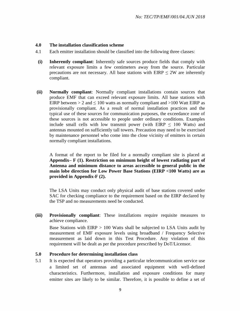
4.0 The installation classification scheme
4.1 Each emitter installation should be classified into the following three classes:
(i) Inherently compliant: Inherently safe sources produce fields that comply with
relevant exposure limits a few centimeters away from the source. Particular
precautions are not necessary. All base stations with EIRP ≤ 2W are inherently
compliant.
(ii) Normally compliant: Normally compliant installations contain sources that
produce EMF that can exceed relevant exposure limits. All base stations with
EIRP between > 2 and ≤ 100 watts as normally compliant and >100 Watt EIRP as
provisionally compliant. As a result of normal installation practices and the
typical use of these sources for communication purposes, the exceedance zone of
these sources is not accessible to people under ordinary conditions. Examples
include small cells with low transmit power (with EIRP ≤ 100 Watts) and
antennas mounted on sufficiently tall towers. Precaution may need to be exercised
by maintenance personnel who come into the close vicinity of emitters in certain
normally compliant installations.
A format of the report to be filed for a normally compliant site is placed at
Appendix– F (1). Restriction on minimum height of lowest radiating part of
Antenna and minimum distance to areas accessible to general public in the
main lobe direction for Low Power Base Stations (EIRP <100 Watts) are as
provided in Appendix-F (2).
The LSA Units may conduct only physical audit of base stations covered under
SAC for checking compliance to the requirement based on the EIRP declared by
the TSP and no measurements need be conducted.
(iii) Provisionally compliant: These installations require requisite measures to
achieve compliance.
Base Stations with EIRP > 100 Watts shall be subjected to LSA Units audit by
measurement of EMF exposure levels using broadband / Frequency Selective
measurement as laid down in this Test Procedure. Any violation of this
requirement will be dealt as per the procedure prescribed by DoT/Licensor.
5.0 Procedure for determining installation class
5.1 It is expected that operators providing a particular telecommunication service use
a limited set of antennas and associated equipment with well-defined
characteristics. Furthermore, installation and exposure conditions for many
emitter sites are likely to be similar. Therefore, it is possible to define a set of

No: TEC/TP/EMF/001/04.JUN 2018
10
reference configurations, reference exposure conditions and corresponding critical
parameters that will enable convenient classification of sites.
5.2 A useful procedure is as follows:
(1) An installation source belongs to the inherently compliant class if the emitter is
inherently compliant (as defined above). There is no need to consider other
installation aspects.
NOTE – An inherently compliant source for International Commission on Non –
ionizing Radiation Protection (ICNIRP) limits has EIRP less than 2 W.
(2) Define a set of reference antenna parameters or antenna types. These categories
can be customized to the types of emitters used for the particular application.
(3) Define a set of accessibility conditions. These categories depend on the
accessibility of various areas in the proximity of the emitter to people. These
categories can be customized to the most commonly occurring installation
environment for the particular service or application.
(4) For each combination of reference antenna parameters and accessibility
condition, determine the threshold EIRP. This threshold EIRP, which will be
denoted as EIRPth, is the value that corresponds to the exposure limit for the
power density or field from the reference antenna for the accessibility condition.
The determination may be performed by calculation or measurements.
(5) For each site, an installation belongs to the normally compliant class, if the
following criterion is fulfilled:
1,
i ith
i
EIRP
EIRP
where EIRPi is the temporal averaged radiated power of the antenna at a
particular frequency i, and EIRPth,i is the EIRP threshold relevant to the particular
antenna parameters and accessibility conditions. For a multiple-antenna
installation, the following two conditions need to be distinguished:
• If the sources have overlapping radiation patterns as determined by
considering the half-power beam width, the respective maximum time-
averaged EIRP should satisfy the criterion.
• If there is no overlap of the multiple sources, they shall be considered
independently.

No: TEC/TP/EMF/001/04.JUN 2018
11
6) Sites that do not meet the conditions for normally compliant classification are
considered provisionally compliant.
For sites where the application of these categories is ambiguous, additional calculations
or measurements will need to be performed.
6.0 EMF evaluation techniques
6.1 Evaluation of EMF for telecommunication installations can be done by following
techniques:
(i) Calculation Method
Following two methods are being prescribed. Either of which could be used
for predicting compliance to the exposure limits for RF electromagnetic fields
from mobile radio base stations.
(a) ITU-T K.52 based Calculation Method for determination of EIRPth
(b) ITU-T K.100 based simplified assessment procedure criteria of minimum
distance and minimum height of radiating antenna.
(ii) Field Measurement Approach. -
(a) Broadband Measurement
(b) Frequency Selective Measurement.
(iii) Electromagnetic mapping by software simulation method.
A flow chart of the exposure assessment for single EMF source of a telecommunication
installation is given in Figure 2.

No: TEC/TP/EMF/001/04.JUN 2018
12
Inherently
Compliant
Accessibility
Normally
Compliant
Provisionally
Compliant
Exposure Measurement
Procedure
Determine the appropriate
EMF limits.
Determine
EIRPth
Determine exposure zone.
No further precautions are
needed
End
Mitigation
Techniques
Frequency
Assessment
procedure not
required
Directivity
Protection measures or
further measurement
not required
Analytical Methods,
Numerical Methods,
Field Measurements
Yes
No
Yes
No
Yes
No
EIRP
< 2W
EIRP <
EIRPth or
≤100
Watts
Are Exposure
zone accessible
Start
Figure 2: Flowchart of assessment of EMF
exposure

No: TEC/TP/EMF/001/04.JUN 2018
13
7.0 Prediction of R.F. Fields
7.1 Equations for Predicting RF fields.
The geometry for calculating exposure at the ground level due to an elevated antenna is
shown in Figure 3.
2 m
Figure 3: Sample configuration for calculating exposure at ground level
An antenna is installed so that the centre of radiation is at the height h above the ground.
The goal of the calculation is to evaluate the power density at a point 2 m above the
ground (approximate head level) at a distance x from the tower. In this example the main
beam is parallel to the ground and the antenna gain is axially symmetrical
(omnidirectional).
To simplify the foregoing, define h' = h – 2 [m]. Using trigonometry,
222 xhR
x
h1–tan
Taking into account reflections from the ground, the power density becomes:
22
)(4
56.2
hx
EIRPFS
NOTE – The factor of 2.56 could be replaced by 4 (i.e., considering a reflection factor of
1) if a more severe approach is necessary.

No: TEC/TP/EMF/001/04.JUN 2018
14
7.2 Field regions
7.2.1 The properties of EM Fields need to be taken into consideration for their
measurement and evaluation. For example:
(i) measurement of both the electric and magnetic components may be necessary in
the non-radiating near field region;
(ii) for numerical prediction: the far-field model usually leads to an overestimation of
the field if applied in near field regions.
Therefore, it is important to be aware of the boundaries of each field region before
starting a compliance procedure.
7.2.1 Near Field Region
i) Reactive near-field zone: It is immediately surrounding the antenna where
reactive field predominates and typically extends to a distance of one wavelength
from the antenna. For compliance with the safe exposure limits, measurement of
both E & H components, or evaluation of SAR is required in this region.
ii) Reactive – radiating near-field region
The transitional region wherein the radiating field is beginning to be important
compared with the reactive component. This outer region extends to a few (e.g.,
3) wavelengths from the electromagnetic source. For compliance with the safe
exposure limits, measurement of both E & H components or evaluation of SAR is
required in this region.
iii) Radiating near-field (Fresnel) zone
The region of the field of an antenna between the reactive near-field and the far-
field region and wherein the radiation field predominates. Here, the electric and
magnetic components can be considered locally normal; moreover, the ratio E/H
can be assumed constant (and almost equal to Z0, the intrinsic impedance of free
space). This region exists only if the maximum dimension D of the antenna is
large compared with the wavelength. For compliance with the safe exposure
limits, measurement of only E component is required in this region.
7.2.2 Far Field Zone-Radiating
The region of the field where the angular field distribution in essentially independent of
the distance from the antenna and the radiated power density [W/m2] is constant. The
inner boundary of the radiating far-field region is defined by the larger between 3 and

No: TEC/TP/EMF/001/04.JUN 2018
15
2D2/ in most of the technical literature (i.e., the limit is 2D2/ if the maximum
dimension D of the antenna is large compared with the wavelength). In the far-field
region, the E and H field components are transverse and propagate as a plane wave.
For compliance with the safe exposure limits, measurement of E or Power (S) is required
in this region.
The above regions are shown in Figure 4 given below (where D is supposed to be large
compared with the wavelength).
K.61_F01
Distance from the source
Radiating far-field
Reactive
near-field
Reactive-
radiating
near-field
Radiating
(Fresnel)
near-field
EM
source
3 2D2/
Figure 4 – Field regions around an EM source
(the antenna maximum dimension D is supposed to
be large compared with the wavelength)
In the case of EMF exposure assessment, however, a large phase difference and thus a
shorter distance marking the beginning of the far-field zone is acceptable. A realistic
practical distance from a large antenna, where the far-field begins is:
Rf= 0.5D2/
Where Rf = distance which marks the beginning of the far-field region
D = the maximum dimension of the antenna
= wavelength, in metres (m)
8.0 Determination of EIRPth
The procedure is the following:
(1) Determine the field or the power density for each point O, where exposure can
occur, for the particular antenna.
(2) Find the maximum power density Smax within the exposure area from this set.
(3) The condition Smax = Slim gives the EIRPth where Slim is the relevant limit
given by the EMF exposure standard at the relevant frequency.

No: TEC/TP/EMF/001/04.JUN 2018
16
This procedure may be performed by calculations methods or by measurements. If
measurements are used, it is necessary to perform them at a number of representative
locations for each accessibility configuration and antenna type.
8.1 Accessibility categories
These categories, which depend on the installation circumstances, assess the likelihood
that a person can access the exceedance zone of the emitter are given in Table 2 below:
Table 2 – Accessibility categories
Accessibility
category Relevant installation circumstances
Figure
reference
1
Antenna is installed on an inaccessible tower – the centre
of radiation is at a height h above ground level. There is a
constraint h > 3 m.
Figure 5 Antenna is installed on a publicly accessible structure
(such as a rooftop) – the centre of radiation is at a height h
above the structure.
2
Antenna is installed at ground level – the centre of
radiation is at a height h above ground level. There is an
adjacent building or structure accessible to the general
public and of approximately height h located a distance d
from the antenna along the direction of propagation. There
is a constraint h > 3 m.
Figure 6
3
Antenna is installed at ground level – the centre of
radiation is at a height h (h > 3 m) above ground level.
There is an adjacent building or structure accessible to the
general public and of approximately height h' located at a
distance d from the antenna along the direction of
propagation.
Figure 7
4
Antenna is installed on a structure at a height h (h > 3 m).
There is an exclusion area associated with the antenna.
Two geometries for the exclusion area are defined:
– A circular area with radius a surrounding the antenna; or
Figure 8
– A rectangular area of size a × b in front of the antenna.
Figure 9

No: TEC/TP/EMF/001/04.JUN 2018
17
h
Figure 5 – Illustration of the accessibility category 1
Figure 6 – Illustration of the accessibility category 2

No: TEC/TP/EMF/001/04.JUN 2018
18
Figure 7 – Illustration of the accessibility category 3
Figure 8 – Illustration of the accessibility category 4, circular exclusion area

No: TEC/TP/EMF/001/04.JUN 2018
19
Figure 9 – Illustration of the accessibility category 4, rectangular exclusion area
8.2 Antenna directivity categories
Antenna directivity is important because it determines the pattern of potential exposure.
High directivity means that most of the radiated power is concentrated in a narrow beam
which may allow good control of the location of the exposure zones.
The antenna pattern is a major determinant and a frequently varying factor in determining
the field. Table 3 presents a description to facilitate classification of antennas into generic
categories. The most important parameter for determining the exposure due to elevated
antennas is the vertical (elevation) antenna pattern. The horizontal (azimuth) pattern is
not relevant because the exposure assessment assumes exposure along the direction of
maximum radiation in the horizontal plane.
Note, however, that the vertical and horizontal patterns determine the antenna gain, and
that horizontal pattern determines the exclusion area for accessibility category 4.

No: TEC/TP/EMF/001/04.JUN 2018
20
Table 3 – Antenna directivity categories
Directivity
category Antenna description Relevant parameters
1 Half-wave dipole None See Figure 10
2 Broad coverage antenna (omnidirectional
or sectional), such as those used for
wireless communication or broadcasting
• Vertical half-power beamwidth:
bw
• Maximum side-lobe amplitude
with respect to the maximum: Asl
• Beam tilt: α
See Figure 11.
3 High-gain antenna producing a "pencil"
(circularly symmetrical beam), such as
those used for point-to-point
communication or earth stations
• Vertical half-power beamwidth:
bw
• Maximum side-lobe amplitude
with respect to the maximum: Asl
• Beam tilt: α
See Figure 11.
Figure 10 – Vertical pattern for a half-wave dipole in vertical polarization

No: TEC/TP/EMF/001/04.JUN 2018
21
Figure 11 – Illustration of terms relating to antenna patterns
8.3 The exclusion area
This clause describes the exclusion areas for accessibility category 4. The exclusion area
depends on the horizontal pattern of the antenna. The relevant parameter is the horizontal
coverage of the antenna. Table 4 presents the exclusion areas for a few typical values of
the horizontal coverage of omnidirectional, sectional or narrow-beam antennas.
Table 4 – Exclusion area as function of horizontal coverage
Horizontal coverage Exclusion area
Omnidirectional Circular area (Figure 8)
120º Rectangular area (Figure 9) b = 0.866a
90º Rectangular area (Figure 9) b = 0.707a
60º Rectangular area (Figure 9) b = 0.5a
30º Rectangular area (Figure 9) b = 0.259a
Less than 5º Rectangular area (Figure 9) b = 0.09a

No: TEC/TP/EMF/001/04.JUN 2018
22
The details of calculation of EIRPth and the relevant formats are covered subsequently in
this document.
9.0 Compliance options available to Service Providers for submission of Self
Certification
Mobile Service Operator may self certify their base station for compliance of limits
mentioned in Table-1, page 7 (or as may be prescribed from time to time) after
assessment of estimated levels of EMR in the 60 meters radius of the base station based
on appropriate methods from amongst the following:
(a) Calculations of EIRP/EIRPth based on ITU-T Recommendation K.52
Assessment of the value of (EIRP/EIRPth) can be made at various publicly accessible
points in the environment surrounding the base station site under study (On rooftop, On
Ground, at adjacent buildings etc…). The assessment is based on the formulae given in
the, Appendix -A. The calculation procedure is detailed with the help of an example in
this document at Section 13.
If the value of (EIRP/EIRPth) is found to be less than unity at all points outside the
exclusion zone, the site will be taken as compliant. A format of the report to be filed for
a normally compliant site is placed at Appendix – B.
(b) : Electromagnetic Mapping by Software Simulation.
Electromagnetic mapping can be done by software simulation based on any of the
methods mentioned in ITU-T Recommendation K-70 / 61, which include the following:
a. Ray tracing model, as per ITU-T rec. K.61.
b. Point Source Model, as per ITU-T rec. K.70 Annex -B
The test results of software simulation are to be presented in the form of power density in
percentage of reference levels prescribed as above for general public for various positions
2 meters above the Roof Top Level of the base station site, Ground level and Roof Top of
adjacent buildings in the vicinity of 60 meters from the base station under consideration.
The site can be self certified as compliant if the electromagnetic mapping by software
simulation are within 50 % of the DoT prescribed limits in terms of power density value
corresponding to the lowest frequency radiated at that site as mentioned in Table No. 1 on
page 7 (may be revised time to time).

No: TEC/TP/EMF/001/04.JUN 2018
23
Details of software simulation are described in section 13.0. Sample format of the reports
are enclosed at Appendix-C.
(c) Broadband Measurements
Broadband measurement facilitates overall exposure from all types of base stations of
mobile services but it does not indicate the individual contributions made by individual
sources such as GSM-900, GSM- 1800, WCDMA, LTE mobile phone services. The
overall measured value of the Power Density with broadband measurement test set, if
found within the reference levels prescribed by DoT for general public, the service
provider may choose to certify the site as normally compliant.
Broadband measurement to be conducted for the frequency range from 700 MHz to 3
GHz. Broadband measurement of power density (watt /sq. m) may be done with an
isotropic field probe.
Broadband measurements will be done for first stage audit verification by LSA Unit to
certify EMF compliance of a site subject to the condition that measured values do not
exceed 50% of DoT prescribed limits in terms of power density value corresponding to
the lowest frequency radiated at that site as mentioned in Table No. 1 on page 7 (may be
revised time to time).
A format of the report for a compliant site (cleared by measurement using Broadband
instruments) is placed at Appendix- D.
Mere exceedance of measured levels beyond 50% of the power density limits under
broadband measurement does not amount to site being non-compliant. In these
circumstances, Frequency Selective measurement should be conducted, as mentioned
below.
(d) Frequency Selective Measurements
Frequency Selective measurements with extrapolation for maximum traffic must be
performed if the broadband measurement exceeds 50 % of limits prescribed by DoT.
For Frequency Selective Measurement Service Operator would be required to assess
contribution of each base station for determination of compliance to limits prescribed for
exposure to the general public before self certification of the base station. For such base
station audit verification by LSA Unit would be carried out by selective measurement as
described in Appendix E-III. Format of the report for Selective Measurement to be filed

No: TEC/TP/EMF/001/04.JUN 2018
24
for a compliant site is placed at Appendix E-I and E-II. Please refer Note at the end of
Appendix E-II for definition of a compliant site.
(e) Calculation of minimum height and minimum distance for Simplified
Assessment Criteria based ITU-T Recommendation K.100
For base station not coming in the definition of shared site, compliance to EMF norms
can be submitted with calculation of minimum height and minimum distance based on
simplified assessment criteria given in ITU-T K.100 recommendation depending on the
EIRP level, antenna installation characteristics such as mounting height, main lobe
direction and distance to other ambient sources.
Format of the report for Simplified Assessment Criteria to be filed for a compliant site is
placed at Appendix- F (1).
10.0 Field Measurement Approach.
Before beginning a measurement, it is important to characterize the exposure situation as
much as possible. An attempt should be made to determine:
(i) The frequency and maximum power of the RF source(s) in question, as well as
any nearby sources.
(ii) Areas those are accessible to the general public.
(iii) If appropriate, antenna gain and vertical and horizontal radiation patterns.
(iv) Type of modulation of the source(s).
(v) If possible, one should estimate the maximum expected field levels, in order to
facilitate the selection of an appropriate survey instrument. For safety purposes,
the electric field (or the far-field equivalent power density derived from the E-
field) should be measured first because the body absorbs more energy from the
electric field. Measurements have to be carried out in publically accessible area
which should be more than 1.3 m away from the antenna main lobe direction. In
many cases it may be best to begin by using a broadband instrument capable of
accurately measuring the total field from all sources in all directions. If the total
field does not exceed the relevant exposure guideline in accessible areas, and if
the measurement technique employed is sufficiently accurate, such a
determination would constitute a showing of compliance with that particular
guideline, and further measurements would be unnecessary.
No: TEC/TP/EMF/001/04.JUN 2018
25
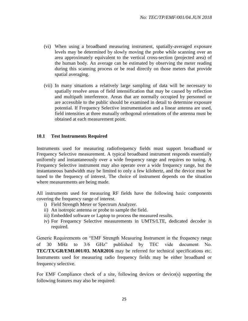
(vi) When using a broadband measuring instrument, spatially-averaged exposure
levels may be determined by slowly moving the probe while scanning over an
area approximately equivalent to the vertical cross-section (projected area) of
the human body. An average can be estimated by observing the meter reading
during this scanning process or be read directly on those meters that provide
spatial averaging.
(vii) In many situations a relatively large sampling of data will be necessary to
spatially resolve areas of field intensification that may be caused by reflection
and multipath interference. Areas that are normally occupied by personnel or
are accessible to the public should be examined in detail to determine exposure
potential. If Frequency Selective instrumentation and a linear antenna are used,
field intensities at three mutually orthogonal orientations of the antenna must be
obtained at each measurement point.
10.1 Test Instruments Required
Instruments used for measuring radiofrequency fields must support broadband or
Frequency Selective measurement. A typical broadband instrument responds essentially
uniformly and instantaneously over a wide frequency range and requires no tuning. A
Frequency Selective instrument may also operate over a wide frequency range, but the
instantaneous bandwidth may be limited to only a few kilohertz, and the device must be
tuned to the frequency of interest. The choice of instrument depends on the situation
where measurements are being made.
All instruments used for measuring RF fields have the following basic components
covering the frequency range of interest.
i) Field Strength Meter or Spectrum Analyzer.
ii) An isotropic antenna or probe to sample the field.
iii) Embedded software or Laptop to process the measured results.
iv) For Frequency Selective measurements in UMTS/LTE, dedicated decoder is
required.
Generic Requirements on “EMF Strength Measuring Instrument in the frequency range
of 30 MHz to 3/6 GHz” published by TEC vide document No.
TEC/TX/GR/EMI.001/03. MAR2016 may be referred for technical specifications etc.
Instruments used for measuring radio frequency fields may be either broadband or
frequency selective.
For EMF Compliance check of a site, following devices or device(s) supporting the
following features may also be required:

No: TEC/TP/EMF/001/04.JUN 2018
26
(a) Built in or plug in GPS Receiver for Longitude-Latitude logging.
(b) Laser Distance Meter.
(c) Digital Camera
(d) Magnetic Compass for azimuth measurement.
(e) Measuring Tape
10.2 Calibration of instruments
It is important that EMF Measuring Instruments should have valid calibration certificate.
Calibration certificate issued by OEM or from an accredited lab (NABL or any
international accreditation under ISO/IEC 17025) will be considered as valid.
11.0 Responsibility of Service Providers at Shared Sites
(1) A shared site may be defined as having:
(a) Multiple base stations on a tower.
(b) Multiple towers with base stations on the same or different plots within 20
m radius.
(c) Multiple Roof Top Poles on with a base station on the same/ Adjacent
Building within 20 m.
(2) Guidelines for capture of the lat/long of base station are as follows:
(a) Lat/long will be recorded in 5 decimal points.
(b) Lat/long to be captured of first clockwise northernmost leg of Tower in
case of GBT/RTT
(c) Lat/long to be captured at the base in case of Monopole (GBMP/RTMP)
(d) A common reference point is specified in order to standardize the process
of measuring the distance between two adjacent sites. In case multiple
RTP/RTT/WM common reference point will be marked at the
approximate geometrical center of the roof in the layout plan of the self
certificate submitted.
(3) For self certification of shared sites,
(a) For new tenancy, only that TSP will submit self-certificate incorporating
details of all constituent base stations on that shared site.

No: TEC/TP/EMF/001/04.JUN 2018
27
In case of upgradation, only the upgrading TSP will submit self-certificate
incorporating details of all constituent base stations on that shared site. All
TSPs shall submit a separate duly digitally signed self-certificate, in the
form of consolidated monthly summary report (to be submitted by 10th
day of the following month), for all the upgrades/additions on shared sites
done by other TSPs, for each LSA. It will be deemed to be a self-
certificate for all technical and legal purposes. The format of the summary
report is at Appendix G.
(4) In case of non-compliance of shared site, penalty shall be imposed as per
DoT instruction.
12.0 Numbering Scheme for Base Station and its Self-Certificates
Development of EMF Portal has necessitated for the standardization of numbering
system for each base station and its associated certifications..
Coding for the numbering of base station will be based on aggregation of ten different
parameters as follows:
SITE-ID LSA / SSA /IP ID / IP Site No.
Base Station-ID LSA/SSA/ IP ID/ IP Site No./ SP /RF Band / Technology / SP Base
Station No.
Certificate Number LSA /SSA /IP ID /IP Site No./ SP /RF Band /Technology /SP Base Station No. /ToS /
DDMMYYYY
Complete Code for Unique Numbering Scheme
Details of different fields used in above nomenclature are as follows:
a. LSA: First classification of any site is based on broad geographical areas i.e. LSA, a
very familiar term in telecom fraternity. Various licenses issued for provision of
telecom services are based on LSA. In above coding LSA will be represented by two
alphanumeric digits, for example- Andhra Pradesh as ‘AP’, Rajasthan as ‘RJ’, etc.
Complete list of LSA coding is available in worksheet “LSA” in Appendix – A
(“Nomenclature.xlsx”)
b. SSA: As an LSA covers a huge area, there was a need to further go down to smaller
geographical units to achieve a better administration and monitoring. Thus it is
proposed to include “SSA” in this nomenclature. In above coding SSA will be
represented by two numeric digit (LSA Madhya Pradesh consists of a maximum 40

No: TEC/TP/EMF/001/04.JUN 2018
28
nos. of SSAs, thus codes 01 to 99 are sufficient), for example- “Adilabad” SSA as
“01”, “Anantpur” SSA as “02”, etc. Complete list of SSA coding is available in
worksheet “SSA” in “Nomenclature.xlsx”. (Also see Note-1).
c. IP ID: Further division for identification of site is based on different Infrastructure
Providers in the LSA. Therefore, this code identifies the “Infrastructure Provider of
the site”. Infrastructure Provider can be anyone of the following:
i. Existing TSP: Presently 206 in number.
ii. Existing ISP: Presently 392 in number.
iii. Existing IP-I: Presently 403 in number.
iv. Any other SP, other than TSP and ISP
IP ID will be represented by four numeric digit ranging from 0001 to 9999. It is
further divided as follows:
i. TSPs: 0001 to 2000
ii. ISPs: 2001 to 5000
iii. IP-Is: 5001 to 7000
iv. Others: 7001 to 9999
(Also see Note-2) These IP IDs are issued by DoT.
d. IP Site No.: This part of coding identifies a specific site of a specific Infrastructure
provider in a particular LSA. Thus the first four part of the above coding together
constitutes to form a nationally-unique-site-identifier and is called as “SITE-ID”
(Figure-1). IP Site No. will be represented by four numeric digit ranging from 0001
to 9999 which will be decided by different IPs (TSPs/ISPs/IP-Is) LSA-wise.
e. SP: This segment of coding identifies a service provider who is responsible for
setting up the radiating elements. An SP can be anyone of the following:
i. Existing TSP of the LSA: Presently 206 in number.
ii. Existing ISP: Presently 392 in number
SP will be represented by four numeric digit ranging from 0001 to 9999. However, it
is further proposed that SP may use the same code allotted to him as an IP ID in (c)
above for better monitoring and administration of sites. (Also see Note-2)
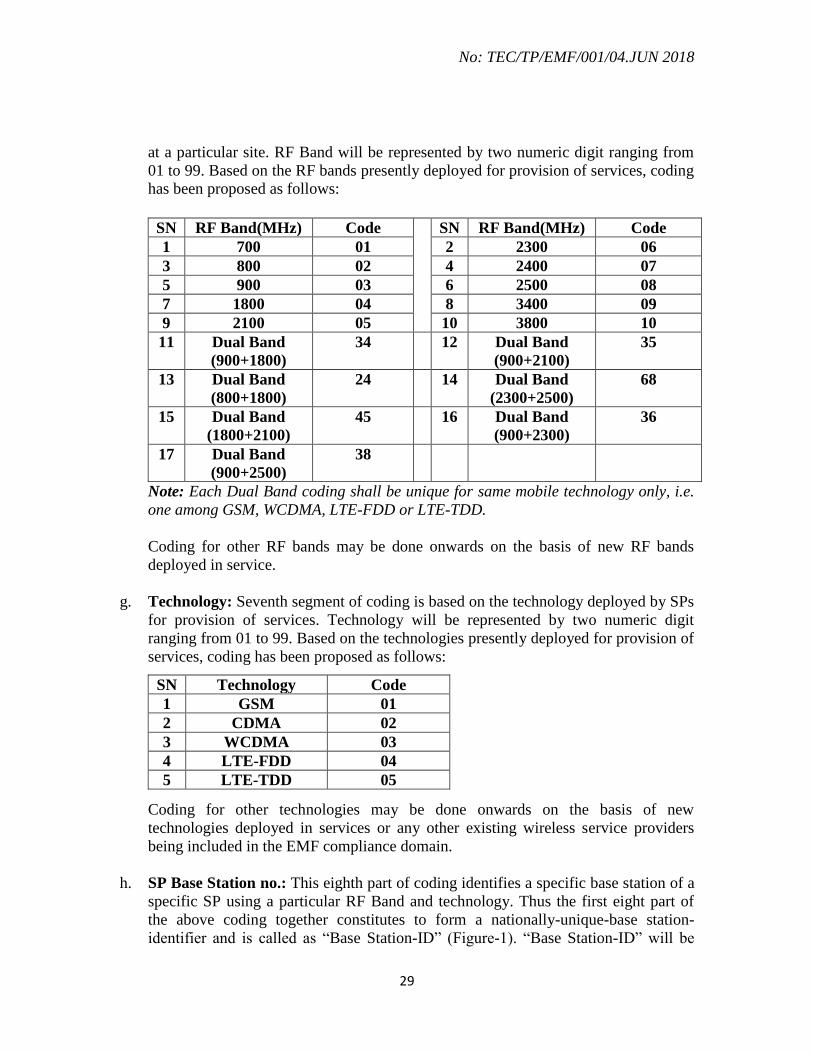
f. RF Band: This is the sixth segment of proposed coding, which represents that RF
Band on which the radiation is taking place by the radiating element installed by SP
No: TEC/TP/EMF/001/04.JUN 2018
29
at a particular site. RF Band will be represented by two numeric digit ranging from
01 to 99. Based on the RF bands presently deployed for provision of services, coding
has been proposed as follows:
SN RF Band(MHz) Code SN RF Band(MHz) Code
1 700 01 2 2300 06
3 800 02 4 2400 07
5 900 03 6 2500 08
7 1800 04 8 3400 09
9 2100 05 10 3800 10
11 Dual Band
(900+1800)
34 12 Dual Band
(900+2100)
35
13 Dual Band
(800+1800)
24 14 Dual Band
(2300+2500)
68
15 Dual Band
(1800+2100)
45 16 Dual Band
(900+2300)
36
17 Dual Band
(900+2500)
38
Note: Each Dual Band coding shall be unique for same mobile technology only, i.e.
one among GSM, WCDMA, LTE-FDD or LTE-TDD.
Coding for other RF bands may be done onwards on the basis of new RF bands
deployed in service.
g. Technology: Seventh segment of coding is based on the technology deployed by SPs
for provision of services. Technology will be represented by two numeric digit
ranging from 01 to 99. Based on the technologies presently deployed for provision of
services, coding has been proposed as follows:
SN Technology Code
1 GSM 01
2 CDMA 02
3 WCDMA 03
4 LTE-FDD 04
5 LTE-TDD 05
Coding for other technologies may be done onwards on the basis of new
technologies deployed in services or any other existing wireless service providers
being included in the EMF compliance domain.
h. SP Base Station no.: This eighth part of coding identifies a specific base station of a
specific SP using a particular RF Band and technology. Thus the first eight part of
the above coding together constitutes to form a nationally-unique-base station-
identifier and is called as “Base Station-ID” (Figure-1). “Base Station-ID” will be

No: TEC/TP/EMF/001/04.JUN 2018
30
represented by four numeric digit ranging from 0001 to 9999 which will be decided
by different SPs (TSPs/ISPs etc.).
i. ToS: This is the ninth segment of above coding which has emerged to identify “Type
of Submission” of a self-certificate by any TSP for a particular base station. Thus
this segment will be a part of different certifications of that base station. Presently,
on the basis of present regulations, the following Types of Submissions” are in-
effect:
SN ToS (Type of Submission) Code
1 Self certificate submission for a new site NS
2 Self certificate submission for a Self-Base Station upgrade US
3 Self certificate submission on Bi-ennial basis BE
4 Revised Self certificate RS
5 Self revised Self certificate SR
j. DDMMYYYY: This is the last segment in above coding which will be used to
identify the date of self-certificate. Here DD represents date of submission, MM
represents month, for example – 01 for January, 12 for December, etc. and YYYY
represents year of submission, for example – 2013, 2014, etc. All the ten segments
together constitute a nationally-unique-EMF-radiation-certificate-number.
Notes:
1. The option of “SSA” has been preferred over “District” as smaller geographical
units. The reason behind this preference is that administrative boundaries of District
are quite volatile in nature in comparison to SSA. Any change in District boundaries
might result into ambiguities in coding/ recognition of the sites lying in affected
areas. However, there is a least possibility of any change in the boundaries of SSAs.
Further, the new license regime (ULs) has also started considering SSAs as sub
telecom units.
2. Presently, coding has been done as per the list provided by different concerned units
of DoT HQ in respect of TSPs, ISPs, and IP-Is. It is proposed to forward this list to
concerned unit after finalization so that in future these codes may be issued by these
units only. This is also in accordance to the “First report of the Committee for
selection/ validation of EMF portal” duly approved by DoT HQ.
3. EMF guidelines issued by DoT HQ are not currently applicable for ISPs. The
numbering scheme will take care of the situation when ISPs or any wireless service
provider is included by DoT in the EMF compliance domain.
4. Base station numbering can undergo change due to changes in data fields like TSP
Site ID, IP Site ID, SSA mapping and other related parameters. TSPs can inform the
LSA Units about such changes through Tarang Sanchar.

No: TEC/TP/EMF/001/04.JUN 2018
31
5. However, a unique ID for each site will be created which shall remain unchanged
and by which one should be able to track the history of changes made at a particular
site
13.0 Compliance by Calculations of EIRP/EIRPth based on ITU-T
Recommendation K.52
As mentioned above in section 10.0 an assessment of the value of (EIRP / EIRPth), is
made at various publicly accessible points in the environment surrounding the base
station site under study (On rooftop, On Ground, and at adjacent buildings). The
assessment is based on the formulae given in the Appendix-A of this document for
measurement of EMF from base station. The data required for these calculations is
enumerated below
13.1 Format of Report for Normal Compliance Calculation
A sample format of the report to be filed with LSA Unit for a site, cleared by calculations
is place at Appendix-B. An explanation of the various terms / data required in this report
is place below:
13.1.1 Site Data
Site ID, Date of Commissioning of base station, Name, Address, Lat / Long (WGS 84),
RTT / GBT, Bldg Ht (in case of RTT), Lowest RF Ant. Ht AGL for each operator.
13.1.2 Adjacent Building Data
The surrounding high rise buildings (first highest building in each main lobe direction)
within the range of 60m which are likely to experience EMF exposure to be marked as
B1, B2, B3 etc…. Following data to be provided for each of these buildings:
Horizontal Distance from the Tower base (m)
Lat/Long of the Tower (Deg)
Height of the buildings (m) AGL
13.1.3 Site Layout
A Site / Roof layout is to be submitted, having marking for North Direction, location of
the Tower / Poles / GBT, marking for corners / points (C1, C2 C3 and C4). The layout is
also to be marked with the location of Safety Signs installed at Site.
13.1.4 Technical Parameters
Technical details of each operator on the Tower need to be provided:

No: TEC/TP/EMF/001/04.JUN 2018
32
Base Station
Technology
CDMA/UMTS/LTE
Frequency Band
(MHz)
700, 850, 900, 1800, 2100, 2300, 2500, 2600
Base Ch. Freq BCCH Freq (GSM) / Center Frequency (CDMA/UMTS/ LTE)
Carriers / Sector
(Worst)
Max. No. of carriers / sector eg. if two sectors are having three
carriers, while the third one has four carriers, the value to be
provided would be four.
Total Tilt In built tilt+Electrical Tilt + Mechanical Tilt (Deg)
Antenna Tx Gain Antenna Gain in dBi
Vertical BW The Base Station Antenna vertical 3 db beam-width (Deg)
Side Lobe Atten The db down value of the largest side lobe, w.r.t to the main
lobe, in the vertical radiation pattern of the antenna.
Tx Power Transmitter Output power (dBm)
Combiner Loss Combiner Loss if any (dB)
Jumper & Connector
Loss
Jumper & Connector Loss if any (dB)
RF Cable Length Length of the RF Cable from Antenna to the Base Station (m)
RF Cable Unit Loss Unit Loss of RF Cable (dB/100m)
13.1.5 Estimation of Total EIRP (EIRP [T]) for each Operator
To calculate the total EIRP (EIRP [T]) for an operator, the EIRP of the BCCH Channel
(Pilot Channel in case of CDMA) is worked out as follows:
EIRP (BCCH) = Tx Power – Combiner Loss – (Cable Length x Unit Loss) + Antenna
Gain (dBm)
The EIRP [T] is then given by:
EIRP [T] =EIRP (BCCH) watts x (Carriers / Sector)
An example of the calculation of EIRP [T] is given below:

No: TEC/TP/EMF/001/04.JUN 2018
33
13.1.6 Estimation of EIRP [T] /EIRPth at Ground
As per, Appendix-. A, the case of calculation of EIRPth for ground points for Base Station
sites falls under Accessibility category 1 and Directivity Category 2. Appropriate
Formulae may be used from Table A.1 (400 – 2000 MHz) or Table A.2 (above 2000
MHz) depending upon Freq Band of Operation.
CALCULATION OF EIRPth FOR ACCESSIBILITY CATEFORY 1
(ON ROADS AT THE GROUND LEVEL)
h
Figure12: Accessibility Category 1
Base Station
TCH
TCH
BCCH 316 W
TCH
TOTAL EIRP
= 948 W
o GSM 1800 o 3 Carriers o Tx O/p = 20 W (43 dBm)
18 dBi Gain
6 dB Loss
No: TEC/TP/EMF/001/04.JUN 2018
34
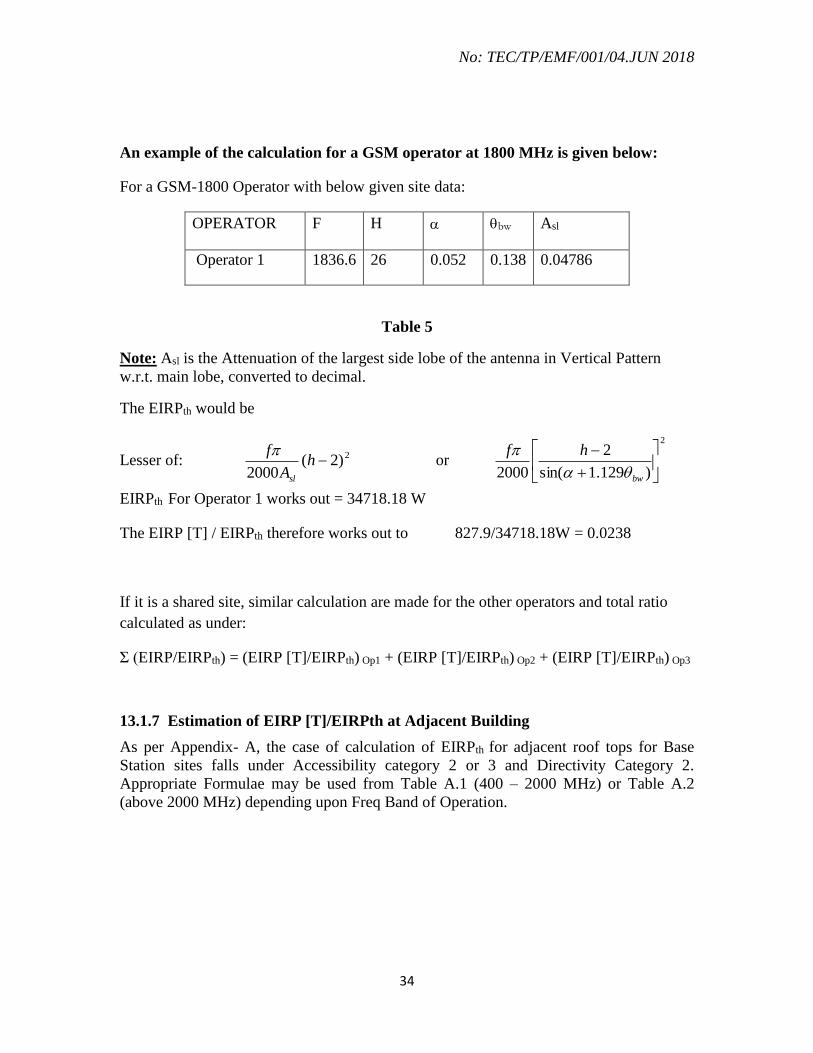
An example of the calculation for a GSM operator at 1800 MHz is given below:
For a GSM-1800 Operator with below given site data:
OPERATOR F H bw Asl
Operator 1 1836.6 26 0.052 0.138 0.04786
Table 5
Note: Asl is the Attenuation of the largest side lobe of the antenna in Vertical Pattern
w.r.t. main lobe, converted to decimal.
The EIRPth would be
Lesser of: 2)2(2000
hA
f
sl
or
2
)129.1sin(
2
2000
bw
hf
EIRPth For Operator 1 works out = 34718.18 W
The EIRP [T] / EIRPth therefore works out to 827.9/34718.18W = 0.0238
If it is a shared site, similar calculation are made for the other operators and total ratio
calculated as under:
Σ (EIRP/EIRPth) = (EIRP [T]/EIRPth) Op1 + (EIRP [T]/EIRPth) Op2 + (EIRP [T]/EIRPth) Op3
13.1.7 Estimation of EIRP [T]/EIRPth at Adjacent Building
As per Appendix- A, the case of calculation of EIRPth for adjacent roof tops for Base
Station sites falls under Accessibility category 2 or 3 and Directivity Category 2.
Appropriate Formulae may be used from Table A.1 (400 – 2000 MHz) or Table A.2
(above 2000 MHz) depending upon Freq Band of Operation.

No: TEC/TP/EMF/001/04.JUN 2018
35
CALCULATION OF EIRPth FOR ACCESSIBILITY CATEFORY 2/3
(ON ADJACENT BUILDING ROOF TOP)
Figure 13: Accessibility Category 2
For a CDMA operator at 800 MHz with site data given below:
OPERATOR F Asl H H D
Operator 2 836.6 0.0724436 34.5 33 10
Table 6
The EIRPth would be
Lesser of: 2)2(2000
hA
f
sl
or
222 )(
2000
d
hhd
A
f
sl
Thus the EIRPth for the Operator 2 works out to be 1304.62 W
Considering 4 carriers / sector, 20W output, 3dB Combiner Loss and 45m Cable (3.69 db
/ 100m Unit Loss) and Antenna gain of 15.8 dbi, the EIRP [T] works out to:
EIRP (Pilot) = 43 – 3 – (45x3.69) + 15.8 = 54.13 dBm = 258W

No: TEC/TP/EMF/001/04.JUN 2018
36
EIRP [T] = 258 x 4 = 1032W
The Ratio EIRP [T] / EIRPth = 1032 / 1304.62 = 0.79
Similar calculations are made for the other operators and total ratio calculated as under:
Σ (EIRP/EIRPth) = (EIRP [T]/EIRPth) Op1 + (EIRP [T]/EIRPth) Op2 + (EIRP [T]
/EIRPth) Op3
13.1.8 Other guidelines for Compliance Calculation
Following points may be taken into consideration for calculations:
(1) EIRP / EIRPth has to be worked out for each operator, at the buildings B1, B2, B3…
defined above at various floors. The calculation has to be made based on the data
defined above and using the formulae given in Appendix A. The sum of the EIRP /
EIRPth at each building should be less than 1 for normal compliance.
(2) EIRP / EIRPth is also to be worked out for each operator, at the roof top level on the
building (B0) on which the base station under observation is installed. The sum of
(EIRP / EIRPth) values for individual operators must be less than 1 for normal
compliance.
(3) EIRP / EIRPth has to be worked out for General Public Exposure on Ground (for both
GBT as well as RTT / RTP case) based on the formulae given in Appendix A. The
sum of values for EIRP / EIRP th should be less than 1 for normal compliance.
(4) Photographs are required for the site, as well as the Buildings B1, B2, B3… etc. at
which the evaluation of EIRP / EIRPth has been done in the report.
14.0 Compliance by Simplified Assessment Procedure Criteria based on ITU-T
Recommendation K.100
14.1 Simplified assessment procedures to be used for single transmitter are provided to
identify a base station which is known to be in compliance with relevant exposure limits
without the necessity of following the general or comprehensive exposure assessment
processes. This is relevant, for example because of the low power transmitted or because
of the position of the antennas of base station with respect to the general public.
14.2. The simplified assessment procedures are based on knowledge of the equivalent
isotropic radiated power (EIRP), and depending on the EIRP level, antenna installation

No: TEC/TP/EMF/001/04.JUN 2018
37
characteristics such as mounting height, main lobe direction and distance to other
ambient sources.
14.3. For low power base station (EIRP ≤ 100 Watts) the report is to be filed by TSP
for such base station site as per the format given in Appendix– F (1)
The base station (EIRP ≤ 100 Watts) shall comply the restriction on minimum height of
lowest radiating part of Antenna and minimum distance to areas accessible to general
public in the main lobe direction as per the table given in Appendix-F (2)”
14.4 For EIRP larger than 100 W, minimum height Hm and minimum distance Dm (in
meters) are to be computed for Cellular Radio Base Stations in for frequencies between
400 MHz and 2 000 MHz are given by the equations below:
14.5 To ensure compliance to the prescribed safety levels / limits for EMF for general
public the Base Station should be installed so that:
(i) the lowest radiating part of the antenna(s) is at a minimum height of Hm metres
above the general public walkway,
(ii) the minimum distance to areas accessible to the general public in the main lobe
direction is Dm metres,
(iii)no other RF sources with EIRP above 100 W is located within a distance of 5Dm
metres in the main lobe direction and within Dm metres in other directions.
A format of the report to be filed for base station site is placed at Appendix– F(1)
15.0 Compliance by Software Simulation
For more complex scattering environments as envisaged in a shared base station site
having multiple towers or multiple antennae mounted on a single tower or multiple
antennas on a roof top in urban area that involve reflections from building, fluctuations in
earth elevations, etc., numerical ray-tracing / point source algorithms are recommended.
No: TEC/TP/EMF/001/04.JUN 2018
38
It would require detailed Electromagnetic mapping of the area around the base station
using appropriate software based on ray tracing / point source method. (Refer to section
I.2.3: Ray Tracing Method of calculation, Appendix-I of ITU-T Rec. K.61, Annex B of
ITU-T K 70 for Point Source Model)
15.1 Format of Report for Software Simulation
A sample format of the report to be filed with LSA Unit for a site, cleared by software
simulation is place at Appendix-C. An explanation of the various terms / data required in
this report is place below:
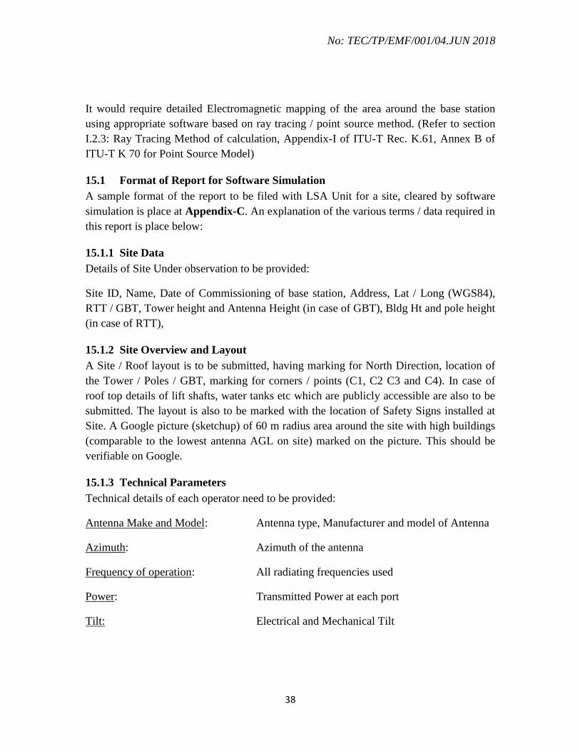
15.1.1 Site Data
Details of Site Under observation to be provided:
Site ID, Name, Date of Commissioning of base station, Address, Lat / Long (WGS84),
RTT / GBT, Tower height and Antenna Height (in case of GBT), Bldg Ht and pole height
(in case of RTT),
15.1.2 Site Overview and Layout
A Site / Roof layout is to be submitted, having marking for North Direction, location of
the Tower / Poles / GBT, marking for corners / points (C1, C2 C3 and C4). In case of
roof top details of lift shafts, water tanks etc which are publicly accessible are also to be
submitted. The layout is also to be marked with the location of Safety Signs installed at
Site. A Google picture (sketchup) of 60 m radius area around the site with high buildings
(comparable to the lowest antenna AGL on site) marked on the picture. This should be
verifiable on Google.
15.1.3 Technical Parameters
Technical details of each operator need to be provided:
Antenna Make and Model: Antenna type, Manufacturer and model of Antenna
Azimuth: Azimuth of the antenna
Frequency of operation: All radiating frequencies used
Power: Transmitted Power at each port
Tilt: Electrical and Mechanical Tilt

No: TEC/TP/EMF/001/04.JUN 2018
39
15.1.4 Adjacent Building Data
The 60 m by 60 m rectangular cross section with the site at the centre of rectangle (in
case of RTT/RTP, centre of rectangular area will be assumed at the notional centre of
such site) are to be surveyed and high rise buildings, which are likely to experience EMF
exposure to be marked as B1, B2, B3 etc…. Following data to be provided for each of
these buildings:
Horizontal Distance from the Tower base (m) or building base (if RTT)
Azimuth from the Tower (Deg)
Height of the adjacent buildings (m) AGL
15.1.5 Orthoslice at Ground Level
Orthoslice (in horizontal plane) at 2 m above ground level of power density in percentage
of current prescribed limits as in section 1.0 for general public is to be submitted with
legend in logarithmic scale and north direction marked. Sample pictures are enclosed at
Appendix- C.
15.1.6 Orthoslice at Roof Top Level
Orthoslice at 2m above rooftop level of power density in percentage of restriction levels
prescribed by DoT for general public is to be submitted with legend in logarithmic scale
and north direction marked. Sample pictures are enclosed at Appendix- C.
15.1.7 Orthoslice for Adjacent Buildings
Orthoslice at the antenna height (to analyze the crossover of exclusion zones with
adjacent nearby buildings in close vicinity, if any) power density in percentage of
restriction levels prescribed in section1.0 for general public is to be submitted with
legend in logarithmic scale and north direction marked.
15.1.8 Compliance Distances/ Exclusion Zone
Sample pictures are enclosed at Appendix- C.
15.1.9 Site Photographs
Photographs are required for the site, as well as the adjacent buildings B1, B2, B3 etc.
16.0 Compliance by Measurements
Measurements can be undertaken for compliance of a site if EIRPth calculations and
electromagnetic mapping by software simulation with Power Density exceeding 50 % of
power density levels prescribed by DOT for general public. Compliance by measurement
would require calibrated instruments as defined in Section 10.2 of this document. The
measurements can first be made using a broadband Meter and would be accepted for

No: TEC/TP/EMF/001/04.JUN 2018
40
compliance if the broadband measurements are within 50% of power density limits
prescribed by DOT as mentioned in Table No. 1 on page 7 (may be revised time to time).
Following sections detail the measurement locations, time limits and other parameters.
16.1 Measurement Spots and Time
At any given base station location under test, the E Field Strength / Power Density
measurements may be undertaken at:
(i) Various points & Corners on the roof top (which are publicly accessible) in case
of RTT / RTP sites.
(ii) On roof top of adjacent buildings, and at various heights if required.
(iii) Representative Locations on Ground Level surrounding the site, if required.
At each location, the measurement will be done for a period not less than 6 minutes, and
RMS value of Electric Field/ Power density will be measured during the above period of
6 minutes.
16.2 DoT Limits for Compliance when using Broadband Instruments
The RMS value of power density as measured above will be compared with the DoT
Limit of the lowest Frequency being used at the base station site.
17.0 Compliance by Broadband Measurements
A sample format of the report to be filed with LSA Unit for a site, cleared by
measurements is placed at Appendix D. An explanation of the various terms / data
required in this report is place below:
17.1 Site Data
Site ID, Name, Date of Commissioning of base station, Address, Lat / Long up to 5
decimal places, RTT / GBT, Bldg Ht (in case of RTT), Lowest RF Ant. Ht AGL for each
operator
17.2 Site Layout
A Site / Roof layout is to be submitted, having marking for North Direction, location of
the Tower / Poles / GBT, marking for corners / points (C1, C2 C3 and C4 etc) where
measurements have been undertaken. The layout is also to be marked with the location of
Safety Signs installed at Site.
No: TEC/TP/EMF/001/04.JUN 2018
41
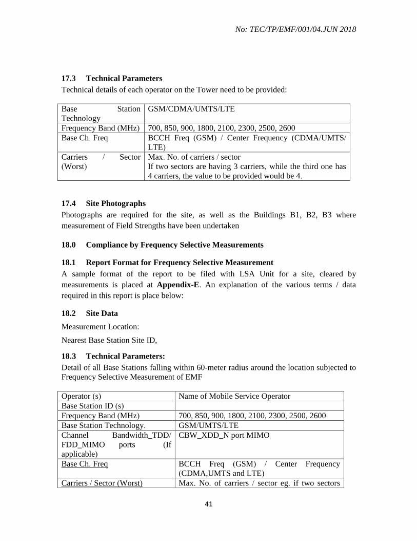
17.3 Technical Parameters
Technical details of each operator on the Tower need to be provided:
Base Station
Technology
GSM/CDMA/UMTS/LTE
Frequency Band (MHz) 700, 850, 900, 1800, 2100, 2300, 2500, 2600
Base Ch. Freq BCCH Freq (GSM) / Center Frequency (CDMA/UMTS/
LTE)
Carriers / Sector
(Worst)
Max. No. of carriers / sector
If two sectors are having 3 carriers, while the third one has
4 carriers, the value to be provided would be 4.
17.4 Site Photographs
Photographs are required for the site, as well as the Buildings B1, B2, B3 where
measurement of Field Strengths have been undertaken
18.0 Compliance by Frequency Selective Measurements
18.1 Report Format for Frequency Selective Measurement
A sample format of the report to be filed with LSA Unit for a site, cleared by
measurements is placed at Appendix-E. An explanation of the various terms / data
required in this report is place below:
18.2 Site Data
Measurement Location:
Nearest Base Station Site ID,
18.3 Technical Parameters:
Detail of all Base Stations falling within 60-meter radius around the location subjected to
Frequency Selective Measurement of EMF
Operator (s) Name of Mobile Service Operator
Base Station ID (s)
Frequency Band (MHz) 700, 850, 900, 1800, 2100, 2300, 2500, 2600
Base Station Technology. GSM/UMTS/LTE
Channel Bandwidth_TDD/
FDD_MIMO ports (If
applicable)
CBW_XDD_N port MIMO
Base Ch. Freq BCCH Freq (GSM) / Center Frequency
(CDMA,UMTS and LTE)
Carriers / Sector (Worst) Max. No. of carriers / sector eg. if two sectors

No: TEC/TP/EMF/001/04.JUN 2018
42
are having three carriers, while the third one has
four carriers, the value to be provided would be
four.
18.4: General comments on measurements
(i) Setting up Measurement Range (MR) has significant impact on readings. The MR
must be set based on the presence of field strength. Start with minimum value of
MR/attenuation and then increase the MR/Attenuation such that instrument just
comes out of saturation mode. Alternatively set for automatic selection for MR, if
feature exist in the instrument.
(ii) Screenshots of the measurement results should be recorded and included in the
Measurement report for the EMF audit.
19.0 Safety Signage
The mobile service operator will ensure provision of proper signage warning for general
public. The sign board should be clearly visible and identifiable and may contain the
following text (as given in the sample below):
The sample of signboard is given below for reference
The rules for placement of signage are as follows:
(1) The signage is to be fixed at an appropriate point on the roof of the building of base
station in case of RTT/RTP or on the tower structure in case of GBT.
(2) For base station installed on self supporting towers/GBM, the safety signage may be
pasted around / install on the tower structure at 2 to 4 meters above the ground level.
Size of Signage: Signage shall be of 200mmX150mm.

No: TEC/TP/EMF/001/04.JUN 2018
43
20.0 LSA Unit Audit
During LSA Unit Audit, following points must be adhered to:
a) For the purpose of audit by LSA Units, only the latest self-certificate
submitted by the TSPs for the site will be considered.
b) EMF Test Instruments for LSA Unit audit must be as per latest TEC GR.
c) LSA Unit is required to formally certify the site to be compliant / non
compliant on the Audit Report, after completion of Audit.
21.0 EMF Portal:
A portal having database of all base stations and their emission compliance status (i.e.
Compliant/Non-compliant) has been launched with the name ‘Tarang-Sanchar’ in May
2017 (tarangsanchar.gov.in).
The salient features and the objectives of the portal are as follows:
1. The Portal disseminates information to the public regarding Electro Magnetic
Field (EMF) emissions for different telecom base stations in an area and to allay
the misconceptions and apprehensions related to health issues of the same.
2. The Portal facilitates Department of Telecom field units and Telecom Operators
to manage technical parameters of a base station for EMF compliance.
3. The portal provides facility to get EMF exposure assessment done at any location
by requesting for the same through the portal on payment of a nominal fee.
22.0 Conclusion
This document is an attempt to cover many practical situations as conceivable. However,
in any peculiar / un-foreseen case, the estimation of EMF exposure should be on a
conservative note and for public good.
No: TEC/TP/EMF/001/04.JUN 2018
44
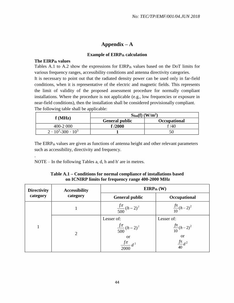
Appendix – A
Example of EIRPth calculation
The EIRPth values
Tables A.1 to A.2 show the expressions for EIRPth values based on the DoT limits for
various frequency ranges, accessibility conditions and antenna directivity categories.
It is necessary to point out that the radiated density power can be used only in far-field
conditions, when it is representative of the electric and magnetic fields. This represents
the limit of validity of the proposed assessment procedure for normally compliant
installations. Where the procedure is not applicable (e.g., low frequencies or exposure in
near-field conditions), then the installation shall be considered provisionally compliant.
The following table shall be applicable:
f (MHz) Slim(f) (W/m2)
General public Occupational
400-2 000 f /2000 f /40
2 · 103-300 · 103 1 50
The EIRPth values are given as functions of antenna height and other relevant parameters
such as accessibility, directivity and frequency.
.
NOTE – In the following Tables a, d, h and h' are in metres.
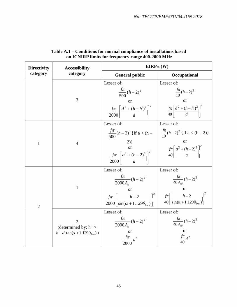
Table A.1 – Conditions for normal compliance of installations based
on ICNIRP limits for frequency range 400-2000 MHz
Directivity
category
Accessibility
category
EIRPth (W)
General public Occupational
1
1 2)2(
500h
f
2)2(10
hf
2
Lesser of:
2)2(500
hf
or
2
2000d
f
Lesser of:
2)2(10
hf
or
2
40d
f
No: TEC/TP/EMF/001/04.JUN 2018
45
Table A.1 – Conditions for normal compliance of installations based
on ICNIRP limits for frequency range 400-2000 MHz
Directivity
category
Accessibility
category
EIRPth (W)
General public Occupational
3
Lesser of:
2)2(500
hf
or 2
22 )(
2000
d
hhdf
Lesser of:
2)2(10
hf
or 2
22 )(
40
d
hhdf
1 4
Lesser of:
2)2(500
hf
{If a < (h –
2)}
or 2
22 )2(
2000
a
haf
Lesser of:
2)2(10
hf
{If a < (h – 2)}
or 2
22 )2(
40
a
haf
2
1
Lesser of:
2)2(2000
hA
f
sl
or 2
)129.1sin(
2
2000
bw
hf
Lesser of:
2)2(40
hA
f
sl
or 2
)129.1sin(
2
40
bw
hf
2
(determined by: h' >
)129.1tan( bwdh )
Lesser of:
2)2(2000
hA
f
sl
or
2
2000d
f
Lesser of:
2)2(40
hA
f
sl
or
2
40d
f

No: TEC/TP/EMF/001/04.JUN 2018
46
Table A.1 – Conditions for normal compliance of installations based
on ICNIRP limits for frequency range 400-2000 MHz
Directivity
category
Accessibility
category
EIRPth (W)
General public Occupational
3
(determined by: h' <
)129.1tan( bwdh )
Lesser of:
2)2(2000
hA
f
sl
or 2
22 )(
2000
d
hhd
A
f
sl
Lesser of:
2)2(40
hA
f
sl
or 2
22 )(
40
d
hhd
A
f
sl
4
Lesser of: 2
22 )2(
2000
a
ha
A
f
sl
or 2
)129.1sin(
2
2000
bw
hf
Lesser of: 2
22 )2(
40
a
ha
A
f
sl
or 2
)129.1sin(
2
40
bw
hf
3 1
Lesser of:
2)2(2000
hA
f
sl
or 2
)129.1sin(2000
bw
hf
Lesser of:
2)2(40
hA
f
sl
or 2
)129.1sin(40
bw
hf
3
2
N/A
(Line of sight is usually
required)
N/A
(Line of sight is usually
required)
3
(determined by: h' <
)129.1tan( bwdh )
Lesser of:
2)2(2000
hA
f
sl
or 2
22 )(
500
d
hhd
A
f
sl
Lesser of:
2)2(40
hA
f
sl
or 2
22 )(
10
d
hhd
A
f
sl

No: TEC/TP/EMF/001/04.JUN 2018
47
Table A.1 – Conditions for normal compliance of installations based
on ICNIRP limits for frequency range 400-2000 MHz
Directivity
category
Accessibility
category
EIRPth (W)
General public Occupational
4
Lesser of: 2
22 )2(
2000
a
ha
A
f
sl
or 2
)129.1sin(
2
2000
bw
hf
Lesser of: 2
22 )2(
40
a
ha
A
f
sl
or 2
)129.1sin(
2
40
bw
hf
Table A.2 – Conditions for normal compliance of installations based on ICNIRP limits for
frequency range 2000-300 000 MHz
Directivity
category
Accessibility
category
EIRPth (W)
General public Occupational
1
1 2)2(4 h 2)2(200 h
2
Lesser of: 2)2(4 h
or 2d
Lesser of:
2)2(200 h
or 250 d
3
Lesser of: 2)2(4 h
or 2
22 )(
d
hhd
Lesser of:
2)2(200 h
or 2
22 )(50
d
hhd

No: TEC/TP/EMF/001/04.JUN 2018
48
Table A.2 – Conditions for normal compliance of installations based on ICNIRP limits for
frequency range 2000-300 000 MHz
Directivity
category
Accessibility
category
EIRPth (W)
General public Occupational
1 4
Lesser of: 2)2(4 h {If a < (h – 2)}
or 2
22 )2(
a
ha
Lesser of:
2)2(200 h {If a < (h –
2)}
or 2
22 )2(50
a
ha
2
1
Lesser of:
2)2( hAsl
or 2
)129.1sin(
2
bw
h
Lesser of:
2)2(50
hAsl
or 2
)129.1sin(
250
bw
h
2
(determined by: h' >
)129.1tan( bwdh )
Lesser of:
2)2( hAsl
or 2d
Lesser of:
2)2(50
hAsl
or 250 d
3
(determined by: h' <
)129.1tan( bwdh )
Lesser of:
2)2( hAsl
or 2
22 )(
d
hhd
Asl
Lesser of:
2)2(50
hAsl
or 2
22 )(50
d
hhd
Asl

No: TEC/TP/EMF/001/04.JUN 2018
49
Table A.2 – Conditions for normal compliance of installations based on ICNIRP limits for
frequency range 2000-300 000 MHz
Directivity
category
Accessibility
category
EIRPth (W)
General public Occupational
4
Lesser of: 2
22 )2(
a
ha
Asl
or 2
)129.1sin(
2
bw
h
Lesser of: 2
22 )2(50
a
ha
Asl
or 2
)129.1sin(
250
bw
h
3 1
Lesser of:
2)2( hAsl
or 2
)129.1sin(
2
bw
h
Lesser of:
2)2(50
hAsl
or 2
)129.1sin(
250
bw
h
3
2
N/A
(Line of sight is usually
required)
N/A
(Line of sight is usually
required)
3
(determined by: h' <
)129.1tan( bwdh )
Lesser of:
2)2( hAsl
or 2
22 )(25.0
d
hhd
Asl
Lesser of:
2)2(50
hAsl
or 2
22 )(5.12
d
hhd
Asl

No: TEC/TP/EMF/001/04.JUN 2018
50
Table A.2 – Conditions for normal compliance of installations based on ICNIRP limits for
frequency range 2000-300 000 MHz
Directivity
category
Accessibility
category
EIRPth (W)
General public Occupational
4
Lesser of: 2
22 )2(
a
ha
Asl
or 2
)129.1sin(
2
bw
h
Lesser of: 2
22 )2(50
a
ha
Asl
or 2
)129.1sin(
250
bw
h
NOTE 1 – f is in MHz.
NOTE 2 – All angles should be expressed in radians.
NOTE 3 – Asl should be expressed as a numerical factor. However, usually, it is given in dB with
respect to the maximum. To convert: 10/][10
dBAsl
slA .

No: TEC/TP/EMF/001/04.JUN 2018
51
Appendix-B
FORMAT FOR CERTIFICATION OF BASE STATION FOR COMPLIANCE OF THE EMF EXPOSURE LEVELS
(CALCULATION OF EIRP/EIRPth)
B-I: SITE DATA & TECHNICAL PARAMETERS
Name of the Base Station : Date :
SITE
DA
TA
Item Units Operator 1 Operator 2 Operator n REMARKS
Site ID
Name
Date of Commissioning
Address
Lat / Long
RTT / GBT
Building Height AGL (m)
Height of Lowest Antenna AGL (m)
TE
CH
NIC
AL
PA
RA
MT
ER
S System Type
(GSM/CDMA/UMTS/LTE)
Base Channel Frequency (MHz)
Carriers / Sector (Worst)
Make and Model of Antenna
Antenna Gain (dBi)

No: TEC/TP/EMF/001/04.JUN 2018
52
Total Tilt (Deg)
Vertical Beamwidth (Deg)
Side Lobe Attenuation (db)
Tx Power (dBm)
Combiner Loss (db)
RF Cable Length (m)
Unit Loss (dB/100m)
EIRP (Base Channel) (W)
DTX factor
ATPC factor
EIRP (TCH) incl DTX , ATPC (W)
EIRP (Total) (W)

No: TEC/TP/EMF/001/04.JUN 2018
53
B-II: EIRP/EIRPth CALCULATION
Co
mp
uta
tio
n o
f o
f
EIR
P/
EIR
Pth
at
Base
Sta
tio
n B
uild
ing
Building 0 (B0) EIRPth at the Building Roof Top Level
Remarks
Lat Long
Operator 1
Operator 2
Operator 3
Overall EIRP/EIRPth
NORMALLY COMPLIANT (YES/ NO)
Co
mp
uta
tio
n o
f o
f E
IR
P/
EIR
Pth
at
ad
jacen
t
bu
ild
ing
s/
co
nsp
icu
ou
s l
ocati
on
s w
ith
in 6
0
mete
rs r
ad
ius.
Building 1 (B1) EIRPth at various floors of the building around the Base Station site
Lat Long
I II III IV Remarks
Operator 1
Operator 2
Operator 3
Overall EIRP/EIRPth
NORMALLY COMPLIANT (YES/ NO)
Building 2 (B2) EIRPth at various floors of the building around the Base Station site
Lat Long
I II III IV Remarks
Operator 1
Operator 2
Operator 3
Overall EIRP/EIRPth
NORMALLY COMPLIANT (YES/ NO)
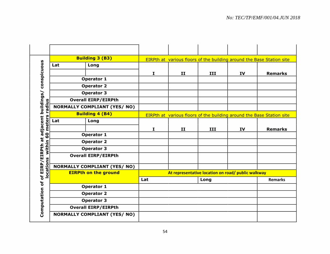
No: TEC/TP/EMF/001/04.JUN 2018
54
Co
mp
uta
tio
n o
f o
f E
IR
P/
EIR
Pth
at
ad
jacen
t b
uil
din
gs/
co
nsp
icu
ou
s
locati
on
s w
ith
in 6
0 m
ete
rs r
ad
ius
Building 3 (B3) EIRPth at various floors of the building around the Base Station site
Lat Long
I II III IV Remarks
Operator 1
Operator 2
Operator 3
Overall EIRP/EIRPth
NORMALLY COMPLIANT (YES/ NO)
Building 4 (B4) EIRPth at various floors of the building around the Base Station site
Lat Long
I II III IV Remarks
Operator 1
Operator 2
Operator 3
Overall EIRP/EIRPth
NORMALLY COMPLIANT (YES/ NO)
EIRPth on the ground At representative location on road/ public walkway
Lat Long Remarks
Operator 1
Operator 2
Operator 3
Overall EIRP/EIRPth
NORMALLY COMPLIANT (YES/ NO)

No: TEC/TP/EMF/001/04.JUN 2018
55
APPENDIX-C
FORMAT FOR CERTIFICATION OF BASE STATION FOR COMPLIANCE OF THE EMF EXPOSURE LEVELS
(BROADBAND MEASUREMENT)
C-I : SITE DATA & TECHNICAL PARAMETERS
Name of the Base Station :
System Type:
SITE
DA
TA
Item Units Operator 1 Operator 2
Operator n REMARKS
Site ID
Name
Date of Commissioning
Address
Lat / Long
RTT / GBT
Building Height AGL (m)
Height of lowest Antenna AGL (m)
Make and model of Antenna
System Type
(GSM/CDMA/UMTS/LTE)
Base Channel Frequencies (MHz) Sec 1, Sec2,
Sec 3
Sec 1,
Sec2, Sec 3
Sec 1, Sec2,
Sec 3
Carriers / Sector Sec1, Sec 2,
Sec 3
Sec1, Sec
2, Sec 3
Sec1, Sec 2,
Sec 3
Tx Power
(dBm)
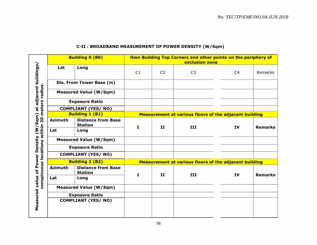
No: TEC/TP/EMF/001/04.JUN 2018
56
C-II : BROADBAND MEASUREMENT OF POWER DENSITY (W/Sqm)
Measu
red
valu
e o
f P
ow
er D
en
sit
y (
W/
Sq
m) a
t ad
jacen
t b
uild
ing
s/
co
nsp
icu
ou
s lo
cati
on
s w
ith
in 2
0 m
ete
rs r
ad
ius.
Building 0 (B0) Own Building Top Corners and other points on the periphery of
exclusion zone
Lat
Long
C1 C2 C3
C4 Remarks
Dis. From Tower Base (m)
Measured Value (W/Sqm)
Exposure Ratio
COMPLIANT (YES/ NO)
Building 1 (B1) Measurement at various floors of the adjacent building
Azimuth Distance from Base
Station I II III
IV Remarks
Lat Long
Measured Value (W/Sqm)
Exposure Ratio
COMPLIANT (YES/ NO)
Building 2 (B2) Measurement at various floors of the adjacent building
Azimuth Distance from Base
Station I II III
IV Remarks
Lat Long
Measured Value (W/Sqm)
Exposure Ratio
COMPLIANT (YES/ NO)

No: TEC/TP/EMF/001/04.JUN 2018
57
Measu
red
valu
e o
f P
ow
er D
en
sit
y (
W/
Sq
m) a
t
ad
jacen
t b
uild
ing
s/
co
nsp
icu
ou
s lo
cati
on
s w
ith
in 2
0
mete
rs r
ad
ius.
Building 3 (B3) Measurement at various floors of the adjacent building
Azimuth Distance from Base
Station I II III
IV Remarks
Lat Long
Measured Value (W/Sqm)
Exposure Ratio
COMPLIANT (YES/ NO)
OT
HE
R R
EP
RE
SE
NT
AT
IV
E
LO
CA
TIO
NS
ON
TH
E G
RO
UN
D
(if
req
uir
ed
)
SPOT LANDMARK Spot 1 Spot 2 Spot 3 Spot 4 Spot 5
Lat
Long
Azimuth
Distance from Base
Station
Measured Value
(W/Sqm)
Exposure Ratio
COMPLIANT (YES/ NO)
NOTE: Reference levels/ limits for EMF exposure to be applied as per the frequency band of the system. This is 13.27 V/m for 900 MHz band
(lowest frequency: 935 MHz) and 18.44 V/m for 1800 MHz band (lowest frequency: 1805 MHz).

No: TEC/TP/EMF/001/04.JUN 2018
58
APPENDIX –D
FORMAT FOR CERTIFICATION OF BASE STATION FOR COMPLIANCE OF THE EMF EXPOSURE LEVELS
(SOFTWARE SIMULATION)
D-I : SITE DATA & TECHNICAL PARAMETERS
Name of the Base
Station : Date :
SITE
DA
TA
Item Units Operator 1 Operator 2 Operator n
Site ID
Name
Date of Commissioning
Address
Lat / Long
RTT / GBT
Building Height AGL (m)
Height of Lowest Antenna AGL (m)
TE
CH
NIC
AL
PA
RA
MT
ER
S
System Type (GSM/CDMA/UMTS)
Frequency of operation (MHz)
Make and Model of Antenna
Antenna Gain (dBi)
Electrical Tilt (Deg)
Mechanical Tilt (Deg)
Tx Power (dBm)

No: TEC/TP/EMF/001/04.JUN 2018
59
D-II :ORTHOSLICE AT GROUND LEVEL
OR
TH
OS
LIC
E A
T G
RO
UN
D L
EV
EL
POWER DENSITY AT 2 M ABOVE THE GROUND LEVEL

No: TEC/TP/EMF/001/04.JUN 2018
60
D-III :ORTHOSLICE AT ROOF TOP LEVEL
OR
TH
OS
LIC
E A
T R
OO
F T
OP
LE
VE
L
POWER DENSITY AT 2 M ABOVE THE ROOF TOP LEVEL

No: TEC/TP/EMF/001/04.JUN 2018
61
EX
CLU
SIO
N D
IS
TA
NC
ES
D-IV : EXCLUSION ZONES AND SAFETY SIGNAGE AT ROOFTOP

No: TEC/TP/EMF/001/04.JUN 2018
62
APPENDIX –E
FORMAT FOR FREQUENCY SELECTIVE MEASUREMENT FOR CERTIFICATION OF BASE
STATIONS FOR COMPLIANCE WITH THE SAFE LIMITS FOR EMF EXPOSURE FROM CELLULAR
RADIO BASE STATIONS
.
E-I: TECHNICAL PARAMETERS FOR BASE STATIONS WITHIN 60 METER RADIUS OF THE
LOCATION UNDER CONSIDERATION
Operator 1 Operator 2 Operator 3 Operator n
BASE STATION ID (s)
Frequency Band (700, 850,
900, 1800, 2100, 2300, 2500,
2600 MHz)
Base Station Technology
(GSM/UMTS/LTE)
Channel
Bandwidth_TDD/FDD_MIMO
ports
(If applicable)
Base Ch. Freq [BCCH Freq
(GSM) / Center Frequency
(CDMA,UMTS and LTE)]
Carriers / Sector (Worst)

No: TEC/TP/EMF/001/04.JUN 2018
63
E-II : Measurements Records
Measurement Location :
Sr.
No.
Op
erat
or
Base Station Technology
(GSM-900/ GSM-1800/UMTS/
LTE-BAND_CBW_XDD_N
port MIMO)
BCCHn /
Scramblin
g Code/
(Cell_ID +
RSi
MIMO
Antenna
Path)
Frequency
(MHz)
[BCCH for
GSM,
Center
Frequency
of CDMA
/UMTS/
LTE]
Measured Value
corresponding to
BCCH (GSM)/
CPICH for each
Scrambling
Code(UMTS)/
Reference Signal RS
Cell specific or the
CPICH signal (LTE)
[d V/m]
Meas
ureme
nt
Uncer
tainty
Extrapolation
Factor [Nc for GSM
/ NCPICH for CDMA/
UMTS/ Ki for
LTE
Correcti
on
Factor
K2 for
TDD
only
[dB]
Extrapolated
Field
Strength
Emax, n
[d V/m]
Emax, n
[V/m]
Limit
Value of
Field
Strength
EG,n
[V/m] Linear dB
(1) (2) (3) (4) (5) (6) (7) (8) (9) (10) (11) (12) (13)
1 GSM-900 BCCH1 936.8 116.4 4 6 122.40 1.3183 13.02
2 GSM-900 BCCH2 946.6 105.3 2 3 108.30 0.2600 13.02
3 GSM-900 BCCH3 948.6 113.9 4 6 119.90 0.9886 13.02
4 GSM-1800 BCCH4 1860.0 109.8 4 6 115.80 0.6166 18.41
5 GSM-1800 BCCH5 1863.8 125.4 4 6 131.40 3.7154 18.41
6 GSM-1800 BCCH6 1864.6 116.4 4 6 122.40 1.3183 18.41
7 UMTS 178 2132.6 103.4 10 113.40 0.4677 19.29
8 UMTS 298 2132.6 117.3 10 127.30 2.3174 19.29
9 UMTS 155 2132.6 101 10 111.00 0.3548 19.29
10 LTE-1800_5_FDD_2-
MIMO 280_0 1846.6 100.5 300 24.8 125.8 1.8408 18.41

No: TEC/TP/EMF/001/04.JUN 2018
64
11 LTE-1800_5_FDD_2-
MIMO 280_1 1846.6 100 300 24.8 124.8 1.7378 18.41
12 LTE-800_10_TDD_2-
MIMO 133_0 816.0 105.6 600 27.8 -1.5 131.9 3.9355 12.28
13 LTE-800_10_TDD_2-
MIMO 133_1 816.0 105 600 27.8 -1.5 131.3 3.6728 12.28
14
Exposure Index
%100......
2
max,
2
2
2max,
2
1
1max,
Gn
n
GG
EE
E
E
E
E
EI = 53.83%*
Note: *For a compliant site, the exposure index shall be within 100%

No: TEC/TP/EMF/001/04.JUN 2018
65
E-III: Application Note on Frequency Selective Measurement of EMF from
channelized mobile/wireless Base Transceiver Stations of various technologies.
Many operators make use of common tower or use the same site to provide
mobile services. If there is any dispute each one will want to show how much their
transmitter is contributing to the overall exposure. That is impossible with a simple,
broadband measurement.
Depending upon the technology used for mobile wireless stations, Spectrum or Code
Analyser performs the measurement of the time invariant signal and applies
appropriate extrapolation to arrive at the power density of the EMF from mobile base
stations under maximum output power condition.
For specific technology of the mobile base station, the time invariant component of
the signal is transmitted at constant power level for specific frequencies within a
certain band. The used time invariant signals for different technologies are:
(1) Broadcast Control Channel (BCCH) in GSM.
(2) Common Pilot Channel (CPICH) signal in UMTS and CDMA systems using
dedicated Scrambling Code Decoder.
(3) Cell specific Reference Signal (RS) in LTE Systems.
(1) GSM Technology:
Time division multiple access (TDMA) mobile phone technology utilise a time
invariant BS radio channel that operates at constant full power and can be used as a
stable reference. In the GSM system this constant power channel is known as the
BCCH.
If the Traffic Channels each operate at a maximum power equal to the constant power
component, which is the case for GSM, then a conservative maximum transmit power
(Pmax) can be determined by multiplying the power of the constant power component
(Pconst) by the total number of carriers that are feed into the antenna, NC (Example: NC
= 4, if BCCH carrier plus 3 additional Traffic Channels are feed into the antenna).
Therefore, the power density corresponding to the maximum emitted power condition
(Smax) can be obtained by measuring the power density in the BCCH (SBCCH) of the
EUT scaled by NC:
CBCCH NSS max
In terms of electric field intensity:
NcEE BCCH max

No: TEC/TP/EMF/001/04.JUN 2018
66
In logarithmic scale : Emax (dBµV/m) = EBCCH (dBµV/m) + 10 log10
Nc
For frequency selective level measurement, the configuration parameters of the EMF
measuring instrument for GSM signals is as follows:
Perform a frequency selective measurement (Spectrum Analyser).
Span: 935 - 960 MHz (GSM-900) and 1805 - 1880 MHz (GSM-1800) or only
a part of the spectrum, if the signals are located in a smaller frequency range
within the band.
RBW = 200 kHz (smaller RBW would lead to an underestimation of the
exposure, higher RBW, e.g. 300 kHz can be accepted, if influence of adjacent
channels on the measurement results is negligible.
Ensure RMS detection of the signal.
Use "Max Hold" function of the instrument and move the measurement
antenna slowly within the volume of investigation to get the spatial maximum.
Watch the instrument display during the measurement and stop measurement,
when no significant changing in the spectrum display appears any more. A
measurement time of six minutes is not necessary.
Example: One operator with a 3 sector antenna system for GSM
Measure the electric field intensity corresponding to BCCH frequency of each sector
antenna.
333max,
222max,
111max,
CBCCHSector
CBCCHSector
CBCCHSector
NEE
NEE
NEE
EBCCHn Value of the measured electric field for the BCCH of nth sector.
NCn Total number of carriers in the nth sector (Typical values:
2…6).
Each extrapolated Electric Field strength Emax value has to be compared with the
corresponding limit EG. EG has to be applied as per the frequency band of the system.
This is 13.27 V/m for 900 MHz band (lowest frequency: 935 MHz) and 18.44 V/m
for 1800 MHz band (lowest frequency: 1805 MHz).
If more than one operator is present at the site, perform this extrapolation and limit
consumption with all BCCH signals radiated from the antennas of the site.
%100......
2
max,
2
2
2max,
2
1
1max,
Gn
nSectror
G
Sector
G
Sector
EE
E
E
E
E
EI

No: TEC/TP/EMF/001/04.JUN 2018
67
EGn: Limit value (electric field strength) for the band used by the antenna. (13.27
V/m for 900 MHz band and 18.44 V/m for 1800 MHz band)
(2) CDMA/WCDMA technology:
Code Division Multiple Access (CDMA) and Wideband Code Division Multiple
Access (WCDMA) technology use spread spectrum technology employing a constant
power control/pilot channel which has a fixed power relationship to the maximum
allocated power.
Dedicated decoding instruments are available that enable the constant power reference
channel (e.g. CPICH in UMTS/WCDMA) to be measured allowing calculation of
maximum RF field strength. In the absence of decoder for CDMA, spectral
measurement method can be used.
If the ratio of the maximum allocated power to the power in the control channel of the
EUT is NCPICH and the measured RF power density from the control channel is SCPICH
then the extrapolated value is:
The parameter NCPICH is set by the telecommunications operator. A typical value is 10
(i.e., 10 % of total power allocated to CPICH).
For code selective level measurement, the configuration parameters of the EMF
measuring instrument for UMTS/WCDMA signals is as follows:
• Measuring Mode: Code selective demodulation
• Center frequency: Centre frequency of the CDMA or UMTS signals; may be
slightly different to the centre frequency of the channel (with steps of 100
kHz). Else the decoding does not work. Service providers often specify a
number denoting the exact centre frequency of a UMTS frequency channel
that they are using. This number is known as the UARFCN (UTRA Absolute
Radio Frequency Channel Number). The corresponding frequency is
determined using the following equation. fcent = UARFCN/5.
Example: UARFCN = 10836 then channel center frequency fcent = 2167.2
MHz.
• Measurement Range: Dependent on the strength of signals to be measured
(typically 20 dB higher than the strongest CPICH signal measured.
CPICHCPICH
CPICH
CPICH NSP
PSS max
max
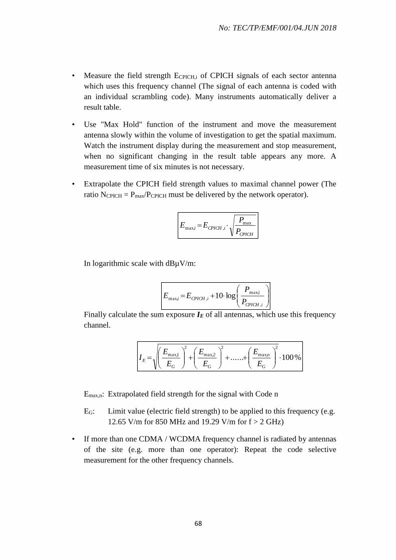
No: TEC/TP/EMF/001/04.JUN 2018
68
• Measure the field strength ECPICH,i of CPICH signals of each sector antenna
which uses this frequency channel (The signal of each antenna is coded with
an individual scrambling code). Many instruments automatically deliver a
result table.
• Use "Max Hold" function of the instrument and move the measurement
antenna slowly within the volume of investigation to get the spatial maximum.
Watch the instrument display during the measurement and stop measurement,
when no significant changing in the result table appears any more. A
measurement time of six minutes is not necessary.
• Extrapolate the CPICH field strength values to maximal channel power (The
ratio NCPICH = Pmax/PCPICH must be delivered by the network operator).
In logarithmic scale with dBµV/m:
Finally calculate the sum exposure IE of all antennas, which use this frequency
channel.
Emax,n: Extrapolated field strength for the signal with Code n
EG: Limit value (electric field strength) to be applied to this frequency (e.g.
12.65 V/m for 850 MHz and 19.29 V/m for f > 2 GHz)
• If more than one CDMA / WCDMA frequency channel is radiated by antennas
of the site (e.g. more than one operator): Repeat the code selective
measurement for the other frequency channels.
CPICH
iCPICHiP
PEE max
,max,
%100......
2
max,
2
2max,
2
1max,
G
n
GG
EE
E
E
E
E
EI
iCPICH
i
iCPICHiP
PEE
,
max,
,max, log10
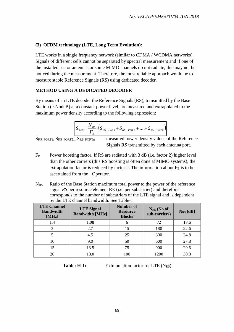
No: TEC/TP/EMF/001/04.JUN 2018
69
(3) OFDM technology (LTE, Long Term Evolution):
LTE works in a single frequency network (similar to CDMA / WCDMA networks).
Signals of different cells cannot be separated by spectral measurement and if one of
the installed sector antennas or some MIMO channels do not radiate, this may not be
noticed during the measurement. Therefore, the most reliable approach would be to
measure stable Reference Signals (RS) using dedicated decoder.
METHOD USING A DEDICATED DECODER
By means of an LTE decoder the Reference Signals (RS), transmitted by the Base
Station (e-NodeB) at a constant power level, are measured and extrapolated to the
maximum power density according to the following expression:
SRS_PORT1, SRS_PORT2… SRS_PORTn measured power density values of the Reference
Signals RS transmitted by each antenna port.
FB Power boosting factor. If RS are radiated with 3 dB (i.e. factor 2) higher level
than the other carriers (this RS boosting is often done at MIMO systems), the
extrapolation factor is reduced by factor 2. The information about FB is to be
ascertained from the Operator.
NRS Ratio of the Base Station maximum total power to the power of the reference
signal RS per resource element RE (i.e. per subcarrier) and therefore
corresponds to the number of subcarriers of the LTE signal and is dependent
by the LTE channel bandwidth. See Table-1
LTE Channel
Bandwidth
[MHz]
LTE Signal
Bandwidth [MHz]
Number of
Resource
Blocks
NRS (No of
sub-carriers) NRS [dB]
1.4 1.08 6 72 18.6
3 2.7 15 180 22.6
5 4.5 25 300 24.8
10 9.0 50 600 27.8
15 13.5 75 900 29.5
20 18.0 100 1200 30.8
Table: H-1: Extrapolation factor for LTE (NRS)
nPortRSPortRSPortRS
B
RS SSSF
NS _2_1_max ....

No: TEC/TP/EMF/001/04.JUN 2018
70
For EMF exposure assessment, the field strength per resource element of RS signals
cell specifically through averaging across a configurable frequency range (span) is to
be measured. Where radiation takes place via multiple antenna ports (MIMO), the RS
signals are to be recorded antenna-specifically.
At LTE base stations, the signals P-SS, S-SS and RS are coded (Cell ID) for specific
cell (Sector Antenna). Cell Specific Reference Signal (RS) is transmitted at every sub-
frame and span all across the operating bandwidth.
Figure H-1: RS radiation scheme for 2 port MIMO
The RS signal can be separated relative to MIMO antenna ports. As displayed in
figure 1, RS0 / RS1 signals are transmitted by the same carriers, but not at the same
time (3 or 4 symbols shift). For 2 port MIMO the values of RS0 and RS1 have to be
measured. Measurement values of RS0 and RS1 can differ due to antenna
characteristic. If 4 antennae MIMO are used, RS2 and RS3 will also be required to be
measured.
The RS field strength is measured as linear average over the field strength
contributions of all resource elements that carry RS within the operating bandwidth.
Thus the measured value corresponds to the average power transmitted for one
subcarrier. If multiple antennas are used for transmission by the same cell (MIMO),
the RS should be determined for each antenna (or antenna port).
In case of LTE-FDD, the maximum electric field strength Emax can also be expressed
as
RS
B
RS EF
NE .max

No: TEC/TP/EMF/001/04.JUN 2018
71
In case of LTE-FDD with smart antenna, the maximum electric field strength Emax can
also be expressed as
RS
B
RS EF
DNE .max
Where ERS is the field strength of RS per RE; NRS is the extrapolation factor for RS,
which is the ratio of the maximum transmission power to transmission power
corresponding to the RS per RE; and FB is the boosting factor for the RS; D is the
beam forming gain of smart antenna.
The extrapolation factor Ki of antenna i therefore is:
..
B
RSii
F
DNK
In logarithmic scale: Ki (dB) = 10 log10 NRS + 10 log10 D - 10 log10 FB
Emax (dBμV/m)= ERS (dBμV/m) + Ki (dB)
Example: One operator with a 3 sector antenna system for LTE and 2 port MIMO
Measure the electric field intensity ERSn corresponding to the RS signals for each
MIMO port of each sector antenna.
Sector 1:
111,1max
100,1max
KEE
KEE
RSPort
RSPort
Sector 2:
211,2max
200,2max
KEE
KEE
RSPort
RSPort
Sector 3:
311,3max
300,3max
KEE
KEE
RSPort
RSPort
In most cases the extrapolation factors Ki are identical for antenna 1, 2 and 3.

No: TEC/TP/EMF/001/04.JUN 2018
72
Finally calculate the sum exposure IE of all antennas and ports.
%100
2
1,3max
2
0,3max
2
1,2max
2
0,2max
2
1,1max
2
0,1max
Gn
Port
Gn
Port
Gn
Port
Gn
Port
Gn
Port
Gn
Port
EE
E
E
E
E
E
E
E
E
E
E
EI
Emax,m,Portn: Extrapolated field strength for the signal with mth Cell ID and nth
MIMO port.
EGn: Limit value (electric field strength) to be applied to this frequency (e.g. 18.44
V/m for 1800 MHz band and 19.29 V/m for f > 2 GHz)
Figure H-2: Typical result of a RS measurement (3 sector antennas with 2 port
MIMO)
For code selective level measurement of EMF exposure from LTE-FDD, the
configuration parameters of the EMF Measuring Instrument is as follows:
• Mode: LTE Analyser / Code demodulation (Cell ID+ MIMO path)
• Center frequency: The centre frequency of the code analyser should be equal
to the centre frequency of the LTE signal.
• RBW = Automatic selection.
• Measurement Range: Dependent on the strength of signals to be measured
(typically 30 dB higher than the strongest RS signal measured.
• Use "Max Hold" function of the instrument and move the measurement
antenna slowly within the volume of investigation to get the spatial maximum.

No: TEC/TP/EMF/001/04.JUN 2018
73
• Extrapolate the RS field strength values to maximal channel power (see
description above).
• In case of LTE-TDD signal, additional correction factor K2 (negative dB
value) is required, because downlink signal is switched off during several sub
frames. This TDD correction factor (ranging from -0.7 to -6.2 dB) depend
upon the UL/DL configuration. K2 = ton/10 ms, where ton is the total time
within a 10 ms frame in which the antenna is radiating RF signals.
Figure H-3: Example for LTE-TDD with ton = 7.1 ms (Check of ton is possible
with Zero Span (time domain) mode of a spectrum analyser).
ALTERNATIVE APPROACH: METHOD WITHOUT DECODING USING A
STANDARD SPECTRUM ANALYSER
For LTE, which uses orthogonal frequency division multiplexing (OFDM)
technology, basic spectrum analyser is less expensive is more commonly available.
However, the power of the Reference Signal (RS) cannot be accurately detected since
they are transmitted on single resource elements spread in frequency and time. To
overcome this, the PBCH power can be measured.
Bit these kinds of measurements have some important disadvantages:
Signals of different cells cannot be separated by this kind of spectrum
analyser measurement and if one of the three sector antenna or some MIMO
channels do not radiate, this may not (!) be noticed during the measurement.

No: TEC/TP/EMF/001/04.JUN 2018
74
Exposure will be overestimated, if the PBCH signals have higher level than
the other parts of the spectrum (at many sites the PBCH signals are boosted by
3 dB).
Exposure will be underestimated by factor 3 dB, if the PBCH signals are not
radiated synchronous but alternately via the MIMO ports.
The PBCH signals are transmitted with the same characteristics regardless of the
configuration or signal bandwidth and span a bandwidth of approximately 1 MHz
over the centre frequency of the LTE signal.
The extrapolation to maximum power is based on the measured field strength
ESYNCH/PBCH, the measurement bandwidth and the total signal bandwidth:
tMeasuremen
Signal
PBCHB
BEE max
EPBCH : Measurement result
BSignal : Signal bandwidth acc. Table 1
BMeasurement: Measurement bandwidth (depending on the used measurement
instrument type, and the filter used, this value will slightly differ).
For a measurement of LTE signals with a simple spectrum analyser, the instrument
should be adjusted as follows:
Use Zero Span (time domain) or Receiver mode of the analyser.
Centre frequency: The center frequency of the instrument should be equal to
the center frequency of the LTE signal.
Measurement Bandwidth (RBW): About 1 MHz
(Smaller RBW can be used as long as all the contributions inside the occupied
bandwidth of the PBCH signal are summed or the influence of the smaller
bandwidth is included into the extrapolation factor.
Detection mode: RMS.
Use sufficient measurement time to catch the maximum signal power (Six-
minute measurement time is not necessary).
In case of LTE-TDD signal, additional correction factor K2 (negative dB
value) is required because downlink signal is switched off during several sub
frames (Details: See code selective measurements of LTE above).

No: TEC/TP/EMF/001/04.JUN 2018
75
Appendix –F(1) FORMAT FOR SIMPLIFIED ASSESSMENT PROCEDURE FOR SELF
CERTIFICATION AS PER ITU-T RECOMMENDATION K.100
SITE DATA & TECHNICAL PARAMETERS
( Applicable only if no other Base Station within 5 * Dm)
Name of TSP :
Name of the Base Station :
Base Station ID :
Sr.
No. Item Units Site Data
1 Site ID
2 Date of Commissioning
3 Address
4 Lat / Long (minimum 5 decimal places) deg
5 Make and model of Antenna/Base Station
6
System Technology
(GSM/CDMA/UMTS/LTE-FDD/TDD)
7
Base Channel Frequencies ( BCCH
(GSM)/CPICH/PBCH and Centre Frequency
(UMTS/LTE) (MHz)
8
Max No. of Carriers in the sector (For GSM) /
MIMO configuration (For LTE)
9 Antenna Tilt deg
10 Antenna Gain dBi
11 Tx Power (dBm)
12 EIRP (dBm)
13 Pole/wall Height (m)
14
Height of lowest part of radiating antenna(s)
from public accessible area (m)
15 Computed value of Hm # (m)
16 Computed value of Dm # (m) # In case of EIRP > 2 Watts and ≤ 100 Watts, the Hm and Dm
values as per Table in Appendix-F(2)
It is to certify that no other RF sources with EIRP above 100 W is located within a
distance of 5Dmmetres in the main lobe direction
Signature of authorized representative of TSP
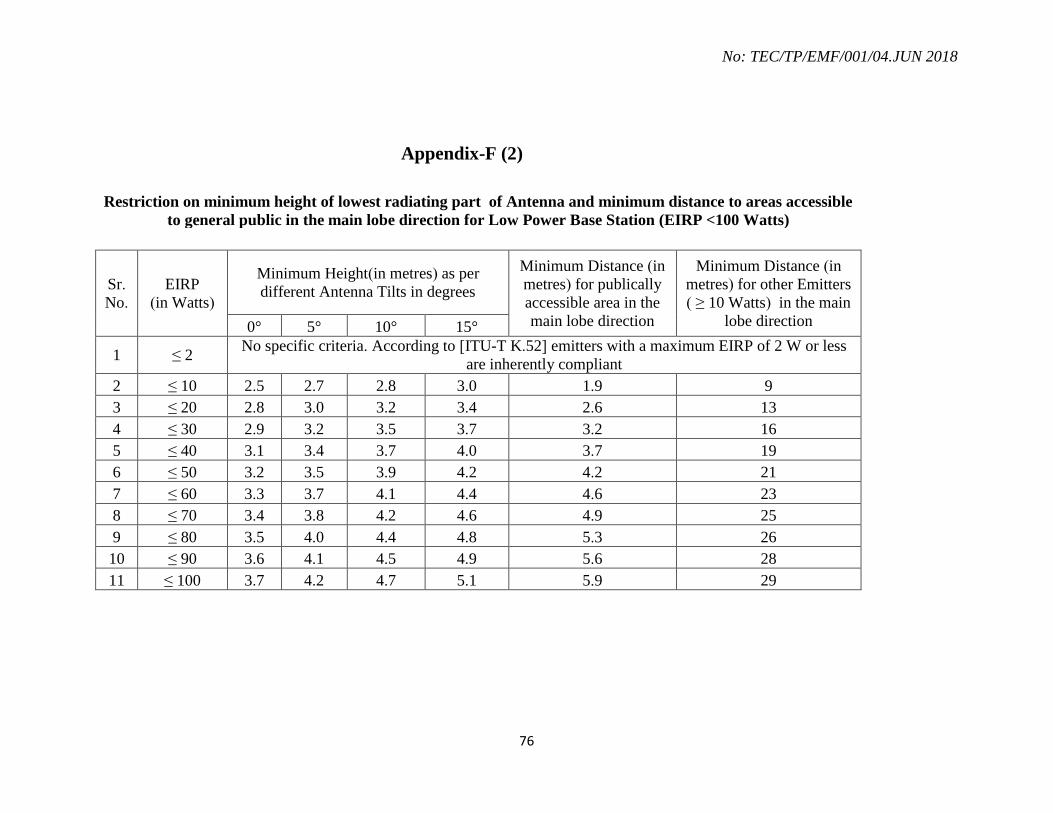
No: TEC/TP/EMF/001/04.JUN 2018
76
Appendix-F (2)
Restriction on minimum height of lowest radiating part of Antenna and minimum distance to areas accessible
to general public in the main lobe direction for Low Power Base Station (EIRP <100 Watts)
Sr.
No.
EIRP
(in Watts)
Minimum Height(in metres) as per
different Antenna Tilts in degrees
Minimum Distance (in
metres) for publically
accessible area in the
main lobe direction
Minimum Distance (in
metres) for other Emitters
( ≥ 10 Watts) in the main
lobe direction 0° 5° 10° 15°
1 ≤ 2 No specific criteria. According to [ITU-T K.52] emitters with a maximum EIRP of 2 W or less
are inherently compliant
2 ≤ 10 2.5 2.7 2.8 3.0 1.9 9
3 ≤ 20 2.8 3.0 3.2 3.4 2.6 13
4 ≤ 30 2.9 3.2 3.5 3.7 3.2 16
5 ≤ 40 3.1 3.4 3.7 4.0 3.7 19
6 ≤ 50 3.2 3.5 3.9 4.2 4.2 21
7 ≤ 60 3.3 3.7 4.1 4.4 4.6 23
8 ≤ 70 3.4 3.8 4.2 4.6 4.9 25
9 ≤ 80 3.5 4.0 4.4 4.8 5.3 26
10 ≤ 90 3.6 4.1 4.5 4.9 5.6 28
11 ≤ 100 3.7 4.2 4.7 5.1 5.9 29

No: TEC/TP/EMF/001/04.JUN 2018
77
Appendix- G
Format for Monthly Summary Report of compliance for TSP XXX (LSA) sites –
Due to upgrades/additions by other TSPs
Note: This Monthly Summary Report has to be submitted by all TSPs for all the upgrades/additions on shared sites done by other TSPs, for
each LSA.
Jurisdiction - LSA, XXXX
Period - Month 1- 2018
1 2 3 4 5 6 7 8 9 10
S.No IP
ID
TSPXXX
Site ID
Other
Tenant's Site
ID
Date of
Upgrade
SC by
other
Tenant
Certificate Id
submitted by
other Tenant for
each upgrade/
addition
Reason for Upgrade -
Increase in TRX/
Electrical, Mechanical
Tilt/ Antenna Change/
TX Power Increase/
Antenna Height/
Antenna Azimuth
Change / New Site
Addition
Compliance
Methodology
EIRP
Ratio
Figure
Certificate of
Compliance
1

No: TEC/TP/EMF/001/04.JUN 2018
78
2
3
4
5
6
7
8
TSP XXX hereby certifies that the mentioned sites are EMF compliant to the laid down guidelines of DoT
vide…….. and amendment to the said instructions from time to time. This Monthly Summary Report will be
deemed to be a self-certificate for all technical and legal purposes.
Name:
Signature:
Date:
Place:

No: TEC/TP/EMF/001/04.JUN 2018
79
Appendix- H
TERMS AND DEFINITIONS
1. antenna gain: The antenna gain G (θ, ) is the ratio of power radiated per unit
solid angle multiplied by 4π to the total input power. Gain is frequently expressed in
decibels with respect to an isotropic antenna (dBi). The equation defining gain is:
d
dP
PG r
in
4),(
where:
θ, are the angles in a polar coordinate system
Pr is the radiated power along the (θ, ) direction
Pin is the total input power
Ω elementary solid angle along the direction of observation
2. average (temporal) power (Pavg): The time-averaged rate of energy transfer
defined by:
2
1
)(1
12
t
tavg dttPtt
P
where t1 and t2 are the start and stop time of the exposure. The period t1 – t2 is the
exposure duration time.
3. averaging time (Tavg): The averaging time is the appropriate time period over
which exposure is averaged for purposes of determining compliance with the limits.
4. continuous exposure: Continuous exposure is defined as exposure for duration
exceeding the corresponding averaging time. Exposure for less than the averaging time is
called short-term exposure.
5. contact current: Contact current is the current flowing into the body by touching
a conductive object in an electromagnetic field.
6. controlled/occupational exposure: Controlled/occupational exposure applies to
situations where persons are exposed as a consequence of their employment and in which
those persons who are exposed have been made fully aware of the potential for exposure
and can exercise control over their exposure. Occupational/controlled exposure also
applies where the exposure is of transient nature as a result of incidental passage through
a location where the exposure limits may be above the general population/uncontrolled
limits, as long as the exposed person has been made fully aware of the potential for
No: TEC/TP/EMF/001/04.JUN 2018
80
exposure and can exercise control over his or her exposure by leaving the area or by some
other appropriate means.
7. directivity: Directivity is the ratio of the power radiated per unit solid angle over
the average power radiated per unit solid angle.
8. Equivalent Isotropically Radiated Power (EIRP): The EIRP is the product of
the power supplied to the antenna and the maximum antenna gain relative to an isotropic
antenna.
9. exposure: Exposure occurs wherever a person is subjected to electric, magnetic or
electromagnetic fields, or to contact currents other than those originating from
physiological processes in the body or other natural phenomena.
10. exposure level: Exposure level is the value of the quantity used when a person is
exposed to electromagnetic fields or contact currents.
11. exposure, non-uniform/partial body: Non-uniform or partial-body exposure
levels result when fields are non-uniform over volumes comparable to the whole human
body. This may occur due to highly directional sources, standing waves, scattered
radiation or in the near field.
12. far-field region: That region of the field of an antenna where the angular field
distribution is essentially independent of the distance from the antenna. In the far-field
region, the field has a predominantly plane-wave character, i.e., locally uniform
distribution of electric field strength and magnetic field strength in planes transverse to
the direction of propagation.
13. general public: All non-workers (see definition of workers in 3.27) are defined as
the general public.
14. induced current: Induced current is the current induced inside the body as a
result of direct exposure to electric, magnetic or electromagnetic fields.
15. intentional emitter: Intentional emitter is a device that intentionally generates
and emits electromagnetic energy by radiation or induction.
16. near-field region: The near-field region exists in proximity to an antenna or other
radiating structure in which the electric and magnetic fields do not have a substantially
plane-wave character but vary considerably from point-to-point. The near-field region is
further subdivided into the reactive near-field region, which is closest to the radiating
structure and that contains most or nearly all of the stored energy, and the radiating near-

No: TEC/TP/EMF/001/04.JUN 2018
81
field region where the radiation field predominates over the reactive field, but lacks
substantial plane-wave character and is complicated in structure.
NOTE – For many antennas, the outer boundary of the reactive near-field is taken to exist
at a distance of one-half wavelength from the antenna surface.
17. power density (S): Power flux-density is the power per unit area normal to the
direction of electromagnetic wave propagation, usually expressed in units of Watts per
square metre (W/m2).
NOTE – For plane waves, power flux-density, electric field strength (E), and magnetic
field strength (H) are related by the intrinsic impedance of free space, 0 = 377 . In
particular,
EHHE
S
20
0
2
where E and H are expressed in units of V/m and A/m, respectively, and S in units of
W/m2. Although many survey instruments indicate power density units, the actual
quantities measured are E or H.
18. general population/uncontrolled exposure: General population/uncontrolled
exposure applies to situations in which the general public may be exposed, or in which
persons who are exposed as a consequence of their employment may not be made fully
aware of the potential for exposure, or cannot exercise control over their exposure.
19. workers: Employed and self-employed persons are termed workers, whilst
following their employment.
20. unintentional emitter: An unintentional emitter is a device that intentionally
generates electromagnetic energy for use within the device, or that sends electromagnetic
energy by conduction to other equipment, but which is not intended to emit or radiate
electromagnetic energy by radiation or induction.
-------------------------------End of Document---------------------------