test on circular steel tube confined uhpc and uhpfrc ... · afgc-aci-fib-rilem int. symposium on...
TRANSCRIPT

AFGC-ACI-fib-RILEM Int. Symposium on Ultra-High Performance Fibre-Reinforced Concrete,
UHPFRC 2017 – October 2-4, 2017, Montpellier, France
499
TEST ON CIRCULAR STEEL TUBE CONFINED UHPC AND UHPFRC
COLUMNS UNDER AXIAL LOADING
Hoang An Le (1) and Ekkehard Fehling (1)
(1) Institute of Structural Engineering, University of Kassel, Germany
Abstract
This paper presents the behavior of ultra high performance concrete with and without steel
fibers (UHPC and UHPFRC) filled circular steel tube columns under axial loading on only
concrete core. The experimental investigation was conducted with six columns having an
outer diameter of 152.4 mm and steel thickness of 8.8 mm. These columns were divided into
short columns with length of 600 mm and long columns with length of 1000 mm. The test
results including load versus axial shortening curves, strength enhancement ratio, and
ductility index were discussed in detail. In general, the confinement effect induced by steel
tube provides an improvement in both strength and ductility for UHPC and UHPFRC. Test
results demonstrated that the addition of steel fibers does not increase the strength
enhancement for confined concrete, whereas the post-peak ductility can be considerably
improved as compared to the columns without steel fibers. Furthermore, the presence of steel
fibers reduces the localization of deformation of steel tube and the sudden drop of load right
after the first peak load.
Résumé
Cet article présente le comportement de poteaux constitués de tubes d’acier circulaires
remplis de béton à ultra-hautes performances sans fibres (BUHP) ou avec fibres métalliques
(BFUP) sous chargement axial uniquement appliqué sur le cœur en béton. L’investigation
expérimentale a été menée sur six poteaux d’un diamètre extérieur de 152.4 mm et d’une
épaisseur d’acier de 8.8 mm. Les poteaux se divisaient en deux groupes, poteaux courts de
600 mm de long et poteaux longs de 1000 mm. L’analyse détaillée des résultats a porté sur
les courbes chargement / raccourcissement axial, le taux d’augmentation de résistance et
l’indice de ductilité. En général, l’effet de confinement provoqué par le tube en acier engendre
une amélioration de ténacité et ductilité pour le BUHP comme pour le BFUP. Les résultats des
tests ont montré que l’addition des fibres d’acier ne contribue pas à l’augmentation de
résistance du béton confiné, mais que la ductilité post-pic peut être considérablement
améliorée par rapport aux poteaux sans fibres d’acier. De plus, la présence de fibres d’aciers
réduit la localisation de la déformation du tube d’acier et la chute brutale de la charge juste
après le pic d’effort.

AFGC-ACI-fib-RILEM Int. Symposium on Ultra-High Performance Fibre-Reinforced Concrete,
UHPFRC 2017 – October 2-4, 2017, Montpellier, France
500
1. INTRODUCTION
It is well-understood that ultra high performance concrete (UHPC) with compressive
strength higher than 150 MPa exhibits a brittle failure under compression, thus leading to a
drawback for its utilization in construction, especially in seismically active regions. On the
other hand, it is also established that lateral confinement of concrete results in a significant
enhancement for its compressive strength and deformability. Therefore, steel tube confined
UHPC columns (STC-UHPCCs) are capable of reducing the inherent brittleness of UHPC
material as well as improving the load bearing capacity [14, 15]. The STC-UHPCCs refer as a
form of UHPC filled steel tube columns (UHPC-FSTCs) under axial loading on only concrete
core. In the past, there were several experimental studies on UHPC-FSTCs under two axial
loading patterns including: on concrete core only and on entire section [4, 8, 9, 11, 12, 13].
These studies demonstrated that for the case of axial loading on entire section, no significant
confinement effect is developed until reaching the peak load. The reason for this is that UHPC
core is crushed before steel tube yields since in the elastic phase the Poisson’s ratio of UHPC
core is smaller than that of steel tube before. As a consequence, these authors suggested that
the confinement effect should be neglected for UHPC-FSTCs under axial loading on entire
section. However, Liew and Xiong (2012) [8] recommended that the tri-axial confinement
effect reaches its maximum when only UHPC core is being loaded, thus improving both
strength and ductility of UHPC-FSTCs. Likewise, Tue et al. (2004) [12] and Schneider (2006)
[11] asserted that loading on UHPC core with thicker steel tube can generate sufficient
confinement and impede the sudden load drop right after the peak load of UHPC-FSTCs.
Based on these findings, in order to obtain more benefits of strength and ductility for UHPC
columns, STC-UHPCCs should be further considered and examined.
To the best knowledge of the authors, experimental studies on UHPC-FSTCs, in general, and
STC-UHPCCs, in particular remain very limited. In addition, all current design codes for
concrete filled steel tube columns (CFSTCs) may be applicable for normal strength concrete
(NSC). Recently, Liew and Xiong (2015) [7] have presented an extended design guideline of
Eurocode 4 (EC4, 2004) for CFSTCs using concrete with cylinder compressive strength up to
90 MPa, while Australia standard (AS, 2014) for CFSTCs in composite bridges and building
allows the concrete cylinder compressive strengths up to 100 MPa. Hence, additional tests on
UHPC-FSTCs under two types of loading patterns as discussed above should be conducted to
investigate the suitability of design codes and to extend their applicability for the case of UHPC.
From the issues highlighted above, this paper aims at reporting on an experimental
investigation into circular STC-UHPCCs on a total of 6 monotonically loaded short and long
columns. The discussion on the testing processing, failure modes and the results of axial load
versus axial shortening curve, strength and ductility enhancement will be presented.
2. EXPERIMENTAL STUDY
2.1 Details of Materials and Test Specimens
UHPC without steel fibers (UHPC) and UHPC with steel fibers of 1% by volume
(UHPFRC-SF1%) and 2% by volume (UHPFRC-SF2%) was used in this study, following the
recipe of M3Q which was developed at University of Kassel during the work on the priority
program (SPP1182) of the German Research Foundation (Deutsche Forschungsgemeinschaft
DFG) [10]. It should be noted that M3Q mix was designed to provide a very high self-
compacting characteristic. The fine-grained UHPC and UHPFRC mix have a water-binder

AFGC-ACI-fib-RILEM Int. Symposium on Ultra-High Performance Fibre-Reinforced Concrete,
UHPFRC 2017 – October 2-4, 2017, Montpellier, France
501
ratio of 0.21 and a maximum grain size of 0.5 mm. The details of the mix proportions are
given in Table 1. The steel fibers with diameter df of 0.175 mm and length lf of 13 mm were
added to the UHPC mix in volume fraction of 1% and 2%. The mechanical properties of steel
fibers are illustrated in Table 2.
Table 1: Composition of UHPC and UHPFRC mixes
Mix composition
Unit Cast 1 Cast 2 Cast 3
UHPC UHPFRC-SF1% UHPFRC-SF2%
Water kg/m3 187.98 187.98 187.98
CEM I 52.5R HS-NA kg/m3 795.4 795.4 795.4
Silica fume kg/m3 168.6 168.6 168.6
Superplasticizer Sika Viscorete 2810 kg/m3 24.1 24.1 24.1 Ground Quartz W12 kg/m3 198.4 198.4 198.4
Quartz sand 0.125/0.5 kg/m3 971 971 971
Steel fibers kg/m3 - 79.31 160.25
Slump flow mm 895/915 885/900 880/865
Table 2: Properties of steel fibers
Diameter df
(mm)
Length lf
(mm)
Aspect ratio
(lf /df)
Density
(g/cm3)
Tensile strength
(MPa)
Elastic Modulus
(GPa)
Characteristics
0.175 13 13/0.175 = 74.29 7.8 2500 200 Smooth and brass
coated surface
As a first series of experimental studies on circular STC-UHPCCs tested at the Laboratory
of Structural Engineering Department of Kassel University, a total of 6 steel tubes (type of
S355J2H) with an outer diameter (D) of 152.4 mm and a steel tube thickness (t) of 8.8 mm
were manufactured for filling with UHPC. The height (L) of short columns and long columns
were 600 mm and 1000 mm, respectively. Figures 1(a)-(b) show the formworks for filling
UHPC into steel tubes, in which steel bars were used to connect the top wooden plate with the
bottom wooden plate of European pallet, thereby holding the steel tube in place and
preventing any movement during the casting process. Due to very high slump flow even with
incorporation of steel fiber volume up to 2% (see Table 1), UHPC and UHPFRC mixes were
directly and vertically poured into steel tubes without vibration (see Figure 1b). Figures 1(c)-
(d) describe the test specimens and the top level of concrete after casting and hardening.
There were 3 batches of concrete mix corresponding with UHPC, UHPCFRC-SF1% and
UHPCFRC-SF2% for 6 columns. The compressive strengths (fc) and elastic modulus (Ec)
were determined from three100200 mm cylindrical specimens for each batch in
accordance with the German standards DIN EN 12390-3:2009-07 [3] and DIN 1048-5 [2],
respectively. Besides, the direct tension tests on 6 notches prisms of 40x40x80 mm to
determine the fiber efficiency and 6 prisms without notches of 40x40x160 mm to determine
the tensile strength (ft) were carried out according to Leutbecher (2008) [6].
The details of circular STC-UHPCCs and concrete properties are presented in Table 3. The
letters in the specimen names indicate volume fraction of steel fibers, steel tube thickness and
the length of steel tube. For example, SF2-t8.8-L600 is the column constructed with 2% of
steel fibers, steel tube thickness of 8.8 mm and steel tube height of 600 mm.

AFGC-ACI-fib-RILEM Int. Symposium on Ultra-High Performance Fibre-Reinforced Concrete,
UHPFRC 2017 – October 2-4, 2017, Montpellier, France
502
(a) (b) (c) (d)
Figure 1: Specimen fabrication
Table 3: Details of specimens
Mix
Specimen name
Steel
fibers
Vol.
(%)
D x t (mm)
Length
of
columns
L (mm)
Length of
concrete
core Lc
(mm)
Compressive
strength fc
(MPa)
Elastic
modulus
Ec (MPa)
Direct
tensile
strength
ft (MPa)
Cast 1 SF0-t8.8-L600 0 152.4 x 8.8 600 551.87 178.9 48370 7.1
SF0-t8.8-L1000 152.4 x 8.8 1000 942.93
Cast 2 SF1-t8.8-L600 1 152.4 x 8.8 600 559.67 195.5 49645 7.3
SF1-t8.8-L1000 152.4 x 8.8 1000 951.27
Cast 3 SF2-t8.8-L600 2 152.4 x 8.8 600 549.83 188.2 48421 8.5
SF2-t8.8-L1000 152.4 x 8.8 1000 943.77
2.2 Test Setup and Instrumentation
To monitor the longitudinal and hoop strain of the steel tube, six single-strain gauges were
attached to the external surface at the mid-height of the steel tube and placed at 120o spacing
around the steel tube perimeter. The axial shortening displacements between two stiff steel
blocks were measured by three Linear Varying Displacement Transducers (LVDTs) which
were placed between two hoop ring stiffeners at 120o apart. The LVDTs were equally spaced
around the steel tube and coincident with the position of the strain gauges. The axial load was
applied by a displacement control of hydraulic testing machine with a maximum capacity of
6300 kN. The axial compression test setup and instrumentation are shown in Figures 2(a)-(b).
Prior to testing, the top surface of concrete core was capped using a very thin layer of sand
(about 4 mm) to ensure even load distribution from the upper stiff steel block to the concrete
core and to provide uniform stress distribution during the testing (see Figure 1d). To avoid
premature local failure at the top region of any column due to lateral pressure on the steel tube
due to the sand, a steel plate was produced and used to confine the column at the top position.
Axial load was applied at a constant displacement rate of 0.01 mm/s up to the ultimate
load. This process was found to be continued well beyond the attainment of ultimate load.
When the performance of post-peak branch was fully observed at the axial displacement of
about 15 mm, the displacement rate was increased up to 0.05 mm/s. The testing was
continued until the axial displacement reached a value of 20 mm. The duration of loading for
each test ranged between 25 and 30 minutes.

AFGC-ACI-fib-RILEM Int. Symposium on Ultra-High Performance Fibre-Reinforced Concrete,
UHPFRC 2017 – October 2-4, 2017, Montpellier, France
503
(a) Sketch of Test setup (b) Photo of Test setup
Figure 2: Test setup and instrumentation
3. TEST RESULTS AND DISCUSSION
3.1 Test observations and failure mode
The values recorded from three LVDTs were observed to be quite similar during testing
process, thus indicating the proper action of the sand layer. In contradiction to the behavior of
unconfined UHPC and UHPFRC cylinder under compression test, there was no loud
cracking/crushing noise emanating from the concrete core around the peak load for all
columns. When the load reached the ultimate load, oblique slip lines appeared on the outer
walls of the steel tubes and expanded along the length of steel tube beyond the ultimate load.
After testing, two small bulges were observed at opposite side of the columns. It can be
inferred from these observations that the failure of the columns is associated with a shear
failure of the concrete core and the steel tube provided a restraint to restrict the slip movement
along the shear plane. Therefore, all columns exhibited a softening behavior due to the shear
failure. However, the ductility and the residual strength could be increased due to the
utilization of comparatively thick steel tubes of 8.8 mm, resulting in small bulges of steel
tube. This phenomenon is supported and explained by some previous studies for high strength
concrete confined by steel tube columns [1, 5, 13].
Short column
Long column

AFGC-ACI-fib-RILEM Int. Symposium on Ultra-High Performance Fibre-Reinforced Concrete,
UHPFRC 2017 – October 2-4, 2017, Montpellier, France
504
The typical failure modes of test specimens with and without internal steel fibers are
presented in Figure 3. The local deformation of the steel tube wall in the specimens SF0-t8.8-
L600 and SF0-t8.8-L1000 were found to be near the top and the bottom of column,
respectively. On the contrary, the local deformation occurred near the mid-height in the
columns using steel fibers. The comparison of failure modes between columns with and
without steel fiber stated that the steel fibers formed bridges across the crack of the concrete
core, leading to a distribution of load to whole column length. Moreover, the outward bulges
in the columns without fiber is more pronounced than those of the columns containing steel
fibers, which can be attributed to the contribution of the steel fibers together with the steel
tube in delaying and minimizing the localized deformation.
(a) SF0-t8.8-L600 (b) SF0-t8.8-L1000 (c) SF2-t8.8-L600 (d) SF2-t8.8-L1000
Figure 3: Failure modes after testing
3.2 Axial load versus axial shortening response
The structural behaviors of confined UHPC and UHPFRC are represented in Figure 4 by
the relations between the axial load and the shortening displacement. In addition, the mean
values of longitudinal and hoop strain recorded from strain gauges at mid-height of steel tube
were plotted against axial loads as illustrated in Figure 5. It can be observed from these
figures that all columns behaved in a similar manner in the ascending branch of the loading
response, performing an almost linear and a short plastic stage until the first peak load (Nu),
then followed by a decrease of load until the second peak load (Nres) at which a slight
recovery of strength developed.
The initial stage of loading is linear and quite similar to unconfined UHPC and UHPFRC.
At this stage, although the load is applied on the concrete core only, the steel tube carries the
load together with the concrete core through the interfacial bond between two materials. The
axial load transfer from the concrete core to the steel tube for all columns was confirmed by
the value of strain gauges which measured the longitudinal strain of steel as seen in Figure 5.
The second stage corresponds to a plastic behavior when the applied load is close to the
ultimate load. The bond at the interface of steel – concrete might be broken because of the
occurrence of relative slip, thus the load is mainly sustained by concrete core while the steel
tube shares less load. Therefore, the load versus shortening curve becomes softer. Otherwise,

AFGC-ACI-fib-RILEM Int. Symposium on Ultra-High Performance Fibre-Reinforced Concrete,
UHPFRC 2017 – October 2-4, 2017, Montpellier, France
505
at the second stage, the lateral dilation of concrete core is quickly increased, which in turn
activates the confinement effect of steel tube. It can be evident from Figure 5 that the values
of hoop strains measured from strain gauges at this stage start increasing, thus indicating the
activation of confinement effect. At the maximum load, the concrete core is crushed and its
strength degrades rapidly, thus the third stage is marked by a gradual load decrease in cases
with UHPFRC core due to the incorporation of steel fibers and a sudden load drop for the
case of a UHPC core due to its extremely brittleness. After obtaining the second peak load,
the final stage is regarded as a strength recovery by an ascending branch. This behavior may
be attributed to the fact that, the larger confining stress and the hardening effect of steel tube
are, a better compensation of the strain-softening of concrete core is achieved, leading to an
increase in axial load again. The slope of the ascending branch in the post-peak stage is
dependent on the confining level.
Among short columns, a more pronounced plastic behavior before the first peak load was
found in the columns using steel fibers. Generally, the decrease of load in descending branch
was gradual for all short columns and the residual strength ratio (Nres/Nu) was about 0.83-0.88.
The specimens SF0-t8.8-L600 (without steel fibers) exhibited a sudden drop of load soon
after the first peak load but the amount of load decrease was extremely small. Afterwards, a
horizontal plateau of load-shortening curve was developed before the load dropped again.
With respect to the short columns using steel fibers, the specimen SF2-t8.8-L600 presented a
steeper drop of load compared to the short specimens SF1-t8.8-L600.
For long columns, it can be clearly seen in Figure 4(b) that after the maximum load was
reached, the specimens SF0-t8.8-L1000 (without steel fibers) performed a sudden and a steep
drop of load of about 15%, while there was a gradual decrease in the gradient of the
descending branch in both specimens SF1-t8.8-L1000 and SF2-t8.8-L1000 with the ratio
Nres/Nu of 0.78 and 0.82, respectively.
(a) Short columns (b) Long columns
Figure 4: Axial load versus shortening curves

AFGC-ACI-fib-RILEM Int. Symposium on Ultra-High Performance Fibre-Reinforced Concrete,
UHPFRC 2017 – October 2-4, 2017, Montpellier, France
506
(a) Short columns (b) Long columns
Figure 5: Axial load versus longitudinal and hoop strain of steel tube
3.3 Strength enhancement and ductility
The confinement effect on the unconfined concrete strength is quantified by means of the
strength enhancement ratio, which is defined as the ratio fcc/fc of the confined strength (fcc) to
the unconfined concrete strength (fc). The confined strength fcc can be calculated by the
following equation:
c
ucc
A
Nf (1)
where Nu is the ultimate load (the first peak load) and Ac is the cross section area of the
concrete core.
The ductility index (DI) defined in Eq. (2) is introduced by numerous studies so as to
evaluate the ability of circular STC-UHPCCs to withstand a large plastic deformation without
a significant loss of load bearing capacity.
u
DI
%85 (2)
in whichΔ85% is the axial shortening when the load decreased to 85% of the ultimate load,
andΔu is equal to the axial shortening at the ultimate load.
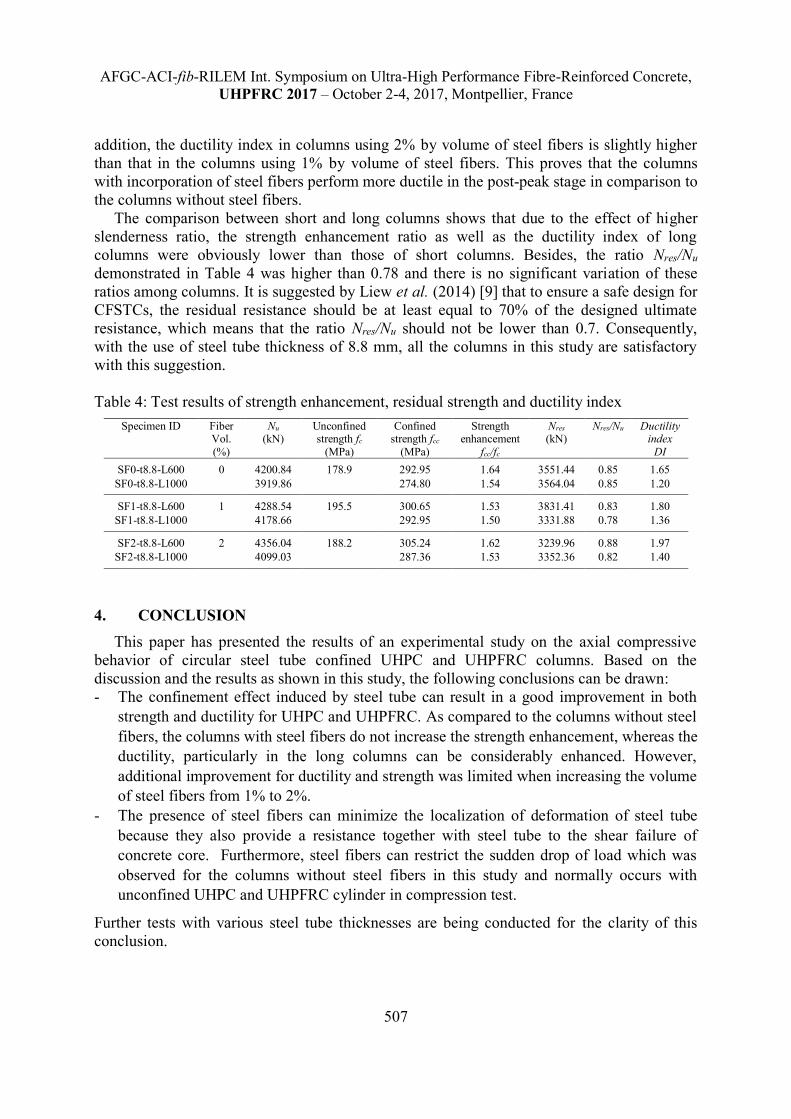
The test results of strength enhancement ratio fcc/fc, ductility index DI and the residual load
(the second peak load Nres) are given in Table 4. As evident in this table, there was no
increase in strength enhancement in the columns with internal steel fibers compared to the
columns without steel fibers. In addition, the increase in steel fiber volume from 1% to 2%
did not significantly increase the strength enhancement. The provision of steel fibers only
slightly increased the unconfined strength of concrete cylinder as compared to the case of no
steel fibers. As noted in some previous studies [1, 5], higher unconfined concrete strength
results in lower confined concrete strength for CFSTCs because lower concrete strength can
generate larger lateral deformation leading to stronger restraint by steel tube and, thus, a
higher confinement effect. Therefore, in this test series, there were no significant differences
in the strength enhancement ratio between the columns using steel fibers up to 2% by volume
and the columns without steel fibers.
With regard to the ductility of columns, it can be seen from Table 4 that the columns using
steel fibers had higher ductility index compared to the columns without steel fibers. In
AFGC-ACI-fib-RILEM Int. Symposium on Ultra-High Performance Fibre-Reinforced Concrete,
UHPFRC 2017 – October 2-4, 2017, Montpellier, France
507
addition, the ductility index in columns using 2% by volume of steel fibers is slightly higher
than that in the columns using 1% by volume of steel fibers. This proves that the columns
with incorporation of steel fibers perform more ductile in the post-peak stage in comparison to
the columns without steel fibers.
The comparison between short and long columns shows that due to the effect of higher
slenderness ratio, the strength enhancement ratio as well as the ductility index of long
columns were obviously lower than those of short columns. Besides, the ratio Nres/Nu
demonstrated in Table 4 was higher than 0.78 and there is no significant variation of these
ratios among columns. It is suggested by Liew et al. (2014) [9] that to ensure a safe design for
CFSTCs, the residual resistance should be at least equal to 70% of the designed ultimate
resistance, which means that the ratio Nres/Nu should not be lower than 0.7. Consequently,
with the use of steel tube thickness of 8.8 mm, all the columns in this study are satisfactory
with this suggestion.
Table 4: Test results of strength enhancement, residual strength and ductility index
Specimen ID Fiber Vol.
(%)
Nu
(kN) Unconfined strength fc
(MPa)
Confined strength fcc
(MPa)
Strength enhancement
fcc/fc
Nres
(kN) Nres/Nu Ductility
index
DI
SF0-t8.8-L600 0 4200.84 178.9 292.95 1.64 3551.44 0.85 1.65
SF0-t8.8-L1000 3919.86 274.80 1.54 3564.04 0.85 1.20
SF1-t8.8-L600 1 4288.54 195.5 300.65 1.53 3831.41 0.83 1.80
SF1-t8.8-L1000 4178.66 292.95 1.50 3331.88 0.78 1.36
SF2-t8.8-L600 2 4356.04 188.2 305.24 1.62 3239.96 0.88 1.97
SF2-t8.8-L1000 4099.03 287.36 1.53 3352.36 0.82 1.40
4. CONCLUSION
This paper has presented the results of an experimental study on the axial compressive
behavior of circular steel tube confined UHPC and UHPFRC columns. Based on the
discussion and the results as shown in this study, the following conclusions can be drawn:
- The confinement effect induced by steel tube can result in a good improvement in both
strength and ductility for UHPC and UHPFRC. As compared to the columns without steel
fibers, the columns with steel fibers do not increase the strength enhancement, whereas the
ductility, particularly in the long columns can be considerably enhanced. However,
additional improvement for ductility and strength was limited when increasing the volume
of steel fibers from 1% to 2%.
- The presence of steel fibers can minimize the localization of deformation of steel tube
because they also provide a resistance together with steel tube to the shear failure of
concrete core. Furthermore, steel fibers can restrict the sudden drop of load which was
observed for the columns without steel fibers in this study and normally occurs with
unconfined UHPC and UHPFRC cylinder in compression test.
Further tests with various steel tube thicknesses are being conducted for the clarity of this
conclusion.
AFGC-ACI-fib-RILEM Int. Symposium on Ultra-High Performance Fibre-Reinforced Concrete,
UHPFRC 2017 – October 2-4, 2017, Montpellier, France
508
ACKNOWLEDGEMENTS
The work presented in this paper was supported by Vietnamese Government for PhD
scholarship and Institute of Structural Engineering – University of Kassel for the project of
UHPC confined by circular steel tube columns. The first author also wishes to thank the
assistance of Dr.-Ing. Jenny Thiemicke, Dipl.-Ing. Beniamino Faion, Dr.-Ing. Thomas Hahn,
Mr. Klaus Trost, Mr. Hendrik Mattfeld, M.Sc. Paul Lorenz who actively participated during
the tests.
REFERENCES
[1] De Oliveira, W.L.A., De Nardin, S., De Cresce El Debs, A.L.H. and El Debs, M.K., ‘Evaluation of
passive confinement in CFT columns’, J. Constructional Steel Research, 66(4), 2010, 487-495.
[2] DIN 1048-5:1991-06, Prüfverfahren für Beton, Teil 5: Festbeton, gesondert hergestellte
Probekörper. Normenausschuss für Bauwesen (NABau) im DIN Deutsches Institut für Norming
e.V., Beuth Verlag GmBH, Berlin, 1991.
[3] DIN EN 12390-3:2009-7, Testing hardened concrete-Part 3: Compressive strength of test
specimens, German version EN 12390-3:2009, Beuth Verlag, Berlin.
[4] Guler, S., Aydogan, M. and Copur, A., ‘Axial Capacity and Ductility of Circular UHPC-filled
Steel Tube Columns’, Magazine of Concrete Research, February, 2013.
[5] Johansson M., ‘The efficiency of passive confinement in CFT columns’, Steel and Compos. Struct,
Int. J, 2(5), 2002, 379-396.
[6] Leutbecher T, ‘Rissbildung und Zugtragverhalten von mit Fasern und Stabstahl bewehrtem
Ultrahochfesten Beton (UHPC)’. Ph.D. Dissertation, Heft 9, kassel university press GmbH,
University of Kassel, Germany, 2008. [In German].
[7] Liew, J.Y.R. and Xiong, M.X., ‘Design Guide For Concrete Filled Tubular Members With High
Strength Materials to Eurocode 4’, Research Publishing, Blk 12 Lorong Bakar Batu, 349568
Singapore, 2015.
[8] Liew, J.Y.R. and Xiong, D.X., ‘Ultra-high strength concrete filled composite columns for multi-
storey building construction’. Adv. Struct. Eng., 15(9), 2012, 1487-1503.
[9] Liew, J.Y.R., Xiong, M.X. and Xiong, D.X., ‘Design of high strength concrete filled tubular
columns for tall buildings’, International Journal of High-Rise Building, 3(3), 2014, 215-221.
[10] Schmidt, M., Fehling, E., Fröhlich, S. and Thiemicke, J., ‘Sustainable Building with Ultra-High
Performance Concrete, Results of the German Priority Programme 1182 funded by Deutsche
Forschungsgemeinschaft (DFG)’, No. 22, 2015, kassel university press GmbH, Germany
[11] Schneider, H., ‘Zum Tragverhalten kurzer, umschnürter, kreisförmiger, Druckglieder aus
ungefasertem UHFB’. Doctoral Dissertation, 2006, University of Leipzig.
[12] Tue, N.V., Schneider, H., Simsch, G. and Schmidt, D., ‘Bearing Capacity of Stub columns
made of NSC, HSC and UHPC confined by a Steel Tube’, in Proceeding of 1st International
Symposium on Ultra High Performance Concrete, kassel university press, Kassel, March 2004,
pp. 339-350.
[13] Xiong, D.X., ‘Structural behaviour of concrete filled steel tube with high strength materials’,
Ph.D. Dissertation, 2012, National University of Singapore, Singapore.
[14] An, L.H. and Fehling, E., ‘Numerical analysis of circular steel tube confined UHPC stub
columns’, Computer and Concrete, 19(3), 2017: 263-273. DOI: 10.12989/cac.2017.19.3.263
[15] An, L.H. and Fehling, E., ‘Analysis of circular steel tube confined UHPC stub columns’, Steel
and Composite Structures, 23(6), 2017: 669-682. DOI: 10.12989/scs.2017.23.6.669.