test and 1/1 eyaluation(u) navy experimental · pdf fileproject, task navy experimental diving...
TRANSCRIPT

AAiB92 RCMRSONCHAMBER COMMUNICATION SYSTEMS TEST AND 1/1EYALUATION(U) NAVY EXPERIMENTAL DIVING UNIT PANAMA CITYFL J D PELTON ET AL. APR 84 NEDU-8-84
UNCLASSIFIED F/O 17/2 NL
EIillllEl lEIiBmImImIIIBB
-~ ~ ~~~ . .~ .... ... .... ...
I-!
11111"2---0 ::lg :111U 211.5
1.0-
118MICROCOPY RESOLUTION TEST CHART
WATIMAI. BUt *J OF STANOAROS - 63-A
2,
" i-;-'-"-"-,. ." "--.-i.,....., .'.' - -"..-.. -.......-.. - .. ',.., .,-. ..... .. .. •.-.,-. .. ..-. ... . . ., ,
"-" " J -* - -'-*' """ " """" '""" " " """" '"" """ ""."""" " "'"" """" "'""" " ,."...".".. .-. .;,'.._.. .-.
,...-"-.".. .,"...'.*.."- -i .". ..
REPROWCEW AT GOVIERNkiP4T EXP~W4S
4~do
*A
CD
NAVY EXPERIMENTAL DIVING UNIT
RECOMPRESSION CHA14BER COMMUNICATION SYSTEMSTEST AND EVALUATION
"iRY [. PELTWI
NAVY EXPERIMENTAL DIVING UIT
4 ~ c'Dig
84 12 12 012
DEPARTMENT OF THE NAVY1/ NAVY EXPERIMENTAL DIVING UNIT
PANAMA CITY. FLORIDA 32407 IN mWPV Wam TW
NAVY IEXPERI14ENTAL DIVING UNIT
REPORT No. 8-84
RECOMPRESSION CHAMBER COMMUNICATION SYSTEMSTEST AND EVALUATION
JERRY D. PELTONMICHAEL D. CURLEY
APRIL 1984
..* ........
Approved for public release; distribution unlimited
Reviewed andSubmitted by: Reviewed by: Approved by:
DPELTON RMIDLETON FRANK E. EISSINGG 13CDR, USN
Test Engineer Senior Projects Officer Commanding Officer
M.D. CURLEYLCDR, MSC, USNHuman Factors Engineer

UNCLASSIFIED___
42CUftITY CLASSIFICATION Of TH41S PAGE (When Date Entered)
READ INSTRUCTIONSREPORT DOCUMENTATION PAGE BEFORE COMPLETING FORM1. REPORT NUMBER I2. ACCESMONO No RECIPIENT'S CATALOG NUMBER
NEDU REPORT NO. 8 -84 AIZ GMIj.~rg4. TITLE (mid Subtitle) s. TYPE OF REPORT & PERIOD COVERED
RECOMPRESSION CHAMBER COMMfUNICATION SYSTEMS FINALTEST AND EVALUATION S. PERFORMING ORG. REPORT NUMBER
7. AUTHOR(s) II. CONTRACT OR GRANT NUMBER(a) -
JERRY D. PELTON and MICHAEL D. CURLEY-
9. PERFORMING ORGANIZATION NAME AND ADDRESS 10. PROGRAM ELEMENT. PROJECT, TASK
NAVY EXPERIMENTAL DIVING UNIT AREA & WORK UNIT NUMBERS
PANAMA CITY, FL 32407
11. CONTROLLING OFFICE NAME AND ADDRESS 12. REPORT DATE
APRIL 198413. NUMBER OF PAGES
14. MONITORING AGENCY NAME aADDRESS(If different from Controlling Office) IS. SECURITY CLASS. (of this report)
UNCLASSIFIED 0tSa. DECL ASSI FICATION/ DOWNGRADING
SCHEDULE
16. DISTRIBUTION STATEMENT (of this Report)
Approved for public release; distribution unlimited.
17. DISTRIBUTION STATEMENT (of the abstract entered In Block 20. If different free Report)
I$. SUPPLEMENTARY NOTES
IS. KEY WORDS (Continue an reverse aide If necessary mid Identify by btock number)------
Hardwire Communicat ions Human FactorsCommunicators MIL-STD-810CDiver PhoneRecompression Chambers
20. ABSTRACT (Continue on reverse side if necessary mid Identify by block number)
_--- Five commercially available Hardwire Communications Systems were testedat the Navy Experimental Diving Unit for use as two-wire communicationssystems on recompression chambers. These systems were designed to serve asthe primary means of communication between outside personnel and personnelinside the chamber. The communication systems were evaluated and rated by how Swell they fulfilled specific critical parameters related to this application.The five systems evaluated were Helle Models 3220 and 3214, Amron Model AMCUM
DD I1JAA75 1473 E0ITION OF INOV 65 IS OBSOLETE UNCLASSIFIED
SECURITY CLASSIFICATION OF THIS PAGE (Wheon Dae Entered)
UNCLASSIFIED
S9CWW?, CLAISIICATION OF THIS PAGE. (Whom Data Eatere
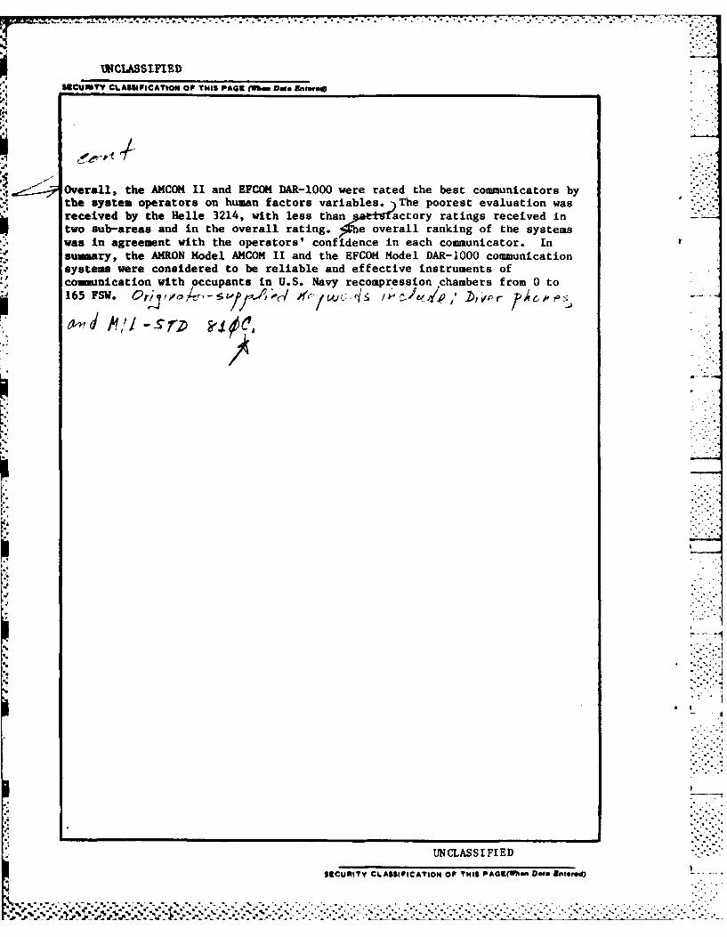
Overall, the AMCOM II and EFCOM DAR-1000 were rated the best communicators bythe system operators on human factors variables. The poorest evaluation wasreceived by the Helle 3214, with less than aut coyrtng eevdiStwo sub-areas and in the overall rating. he ove rall ranking of the systemswas in agreement with the operators' confidence in each communicator. Insuary, the AMRON Model ANCOM II and the EFCOM Model DAR-1000 communicationsystems were considered to be reliable and effective instruments of
!Joimaunication with occupants in U.S. Navy recompression chambers from 0 to165 FSW. 4r",dA~ U/-!S '~c P' v ri e Fos
UNCLASSIFIED
SECURITY CLASSIFICATION OF THIS PAGEWbefl Dae. Entoeed)
'I7 .7 -- o- --. - .-. - -
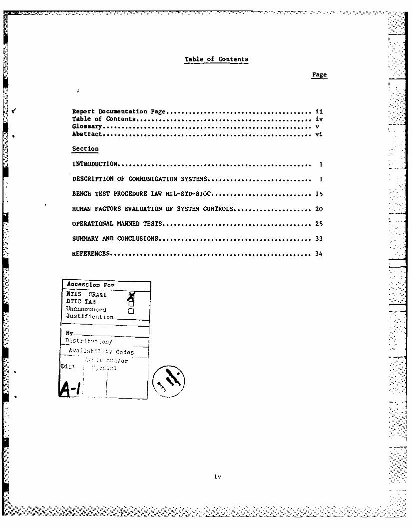
Table of Contents
Page
Vt ~~Report Documentation Page. . . .. .. . .. . ... . .. . .. . ... . .. . ..........
Glossary. " .. . .. . 0 .. .. 00.. ************* *********** *.. . . . . . . . . . . . V
Section
INTRODUCTION.* ................................................. 1
DESCRIPTION OF COMMUNICATION SYSTEMS............ ....... ........ 1
BENCH TEST PROCEDURE IAW MIL-STD-810C ........................... 15
HUMAN FACTORS EVALUATION OF SYSTEM CONTROLS......................20
OPERATIONAL MANNED TESTS. ... .. .. .. .. .. . ... . .... . .. .. .. .. .. . .. .. o. 25
SUMMARY AND CONCLUSIONS. .. .. .. .. . .. . . . . . . . . . . . . . ............ . .. 33
......................................................................... 34
Accession F y or e
NNI.GR;
'o.
-By_
.4i.
iv
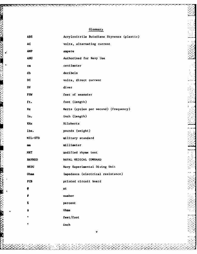
Glossary
ABS Acrylonitrile Butadiene Styrenes (plastic)
AC volts, alternating current
AMP ampere
ANU Authorized for Navy Use
-. cm centimeter
db decibels
DC volts, direct current
DV diver
FSW feet of seawater
ft. foot (length)
Hz Hertz (cycles per second) (frequency)
In. inch (length)
K"z Kilohertz
lbs. pounds (weight)
MIL-STD military standard
mm millimeter
MRT modified rhyme test
NAVMED NAVAL MEDICAL COMMAND
NEDU Navy Experimental Diving Unit
Ohms Impedance (electrical resistance)
PCB printed circuit board
@ at
# number
2 percent
Ohms
feet/foot
inch
v
.. . *•. . ... ...... . ...-. .- -.- • -.--....-..-.. . . .--.... -.. ... .. .. - --.. . ,-. -. -..-..--.-..- --"q " "J *o " .. '""-". . ,, .- . . " .- "-"- . -* . . . . . . . ,, . . . . . . """"-""""'-"""""""""°""" . -"-"""""""""-"
". ",. ,_% '_.'_"
"._' . . ", % ... .-. .,.... . .... -..... . . . . . . . . . . . . . . .. . % . ". ". ' - -. *. - % . . . ". " " " . . ". '

ABSTRACT
Five commercially available Hardwire Communications Systems were testedat the Navy Experimental Diving Unit for use as two-wire communicationssystems on recompression chambers. These systems were designed to serve asthe primary means of communication between outside personnel and personnelinside the chamber. The communication systems were evaluated and rated by howwell they fulfilled specific critical parameters related to this application.The five systems evaluated were Helle Models 3220 and 3214, Amron Model AMCOMI 2820, EFCOM Model DAR-1000, and Atkinson Dynamics Model AD-27H-M2.Overall, the AMCOM II and EFCOM DAR-1000 were rated the best communicators bythe system operators on human factors variables. The poorest evaluation wasreceived by the Helle 3214, with less than satisfactory ratings received intwo sub-areas and in the overall rating. The overall ranking of the systems
was in agreement with the operators' confidence in each communicator. Insummary, the AMRON Model AMCOM II and the EFCOM Model DAR-1000 communicationsystems were considered to be reliable and effective instruments ofcommunication with occupants in U.S. Navy recompression chambers from 0 to165 FSW.
1
KEY WORDS:
Hardwire CommunicationsCommunicatorsDiver PhoneRecompression ChambersHuman FactorsMIL-STD-810C
v i%' '=
* , .-.-*

-.- . ' • -. r - .- -- . . . .
INTRODUCTION
The purpose of this test was to evaluate the adequacy of fivecommercially available Hardwire Communications Systems to meet the Navyrequirements for chamber use. All tests were conducted by Navy ExperimentalDiving Unit (NEDU) personnel at Panama City, Florida and were under the
auspices of NEDU Test Plan 83-28 "Evaluation of Commercially AvailableUnderwater Hardwire Telephone (Hardwire Diver's Communication Systems)". Thisreport correlates the test results and presents evaluation comparisons on theHELLE Models 3220 and 3214, AMRON Model AMCOM II 2820, EFCOM Model DAR-1O00,
and the ATKINSON DYNAMICS Model AD-27H-M2. The evaluation presentationincludes:
A. An assessment of the safety and human engineering characteristics of
the communications systems as a result of bench tests and user inputs(APPENDICES BI, B2 and B3).
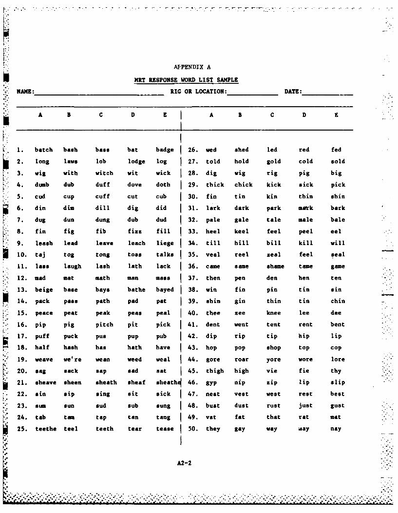
B. A word intelligibility assessment using the Modified Rhyme Test (MRT)which was conducted with both equipment and operators subjected to the actualconditions of expected use (sample APPENDIX Al and A2). ."
C. A study of the interoperability of these communicators with existingequipment, i.e. chambers, transceivers and wiring.
DESCRIPTION OF COMMUNICATION SYSTEMS
Five Hardwire Communications Systems were tested and are pictured inFigure 1. The manufacturers' addresses and model numbers of the systemstested are shown in Table 1. Each system was purchased directly from itsrespective manufacturer and shipped to Panama City, Florida, where all of thetesting was conducted. A brief description of each system follows.
HELLE Model 3114 Wire Diver Phone. The 3214 wire diver phone (Figure 2) is anintercom system between a surface tender and from one to three divers (in thiscase personnel inside the recompression chamber) at the same time or to each.diver individually. Specifications for the communicator are listed in
Table 2.
The system was packaged in an ABS plastic case with a flat cover of thesame material. The front panels were aluminum with descriptive lettering 'silkscreened onto the panels, and all connections were made on the frontpanels. The system as tested was powered by two internal lantern type 6 VDCbatteries which were each connected in series for the 12 VDC needed to powerthe unit. A low voltage indicator light on the front panel was set toactivate when the operating voltage fell below 7 VLC. The cabinet speakerfunctions as both a speaker and a microphone; the speakers inside the testchamber provided the same dual function. The system was tested in the twoI wire mode (see Figure 3 for wiring layout).
% %S-* -. :, -, : -.- , - ..-..-.-. ' .... ........ . . ...... . ..-.-...-.. ... .... .-. . . ... . . . . .. .. . . . .

6.77777 .7 7 .. .
00 I
FIGURE 1. The five Hardwire Communication Systems evaluated for chamber use.
2 ...

TABLE 1
LIST OF MANUFACTURERS ..
Manufacturer Model Number
HELLE ENGINEERING, INC. 3214 Wire Diver Phone7198 Convoy Court andSan Diego, CA 92111 3220 Wire Diver Phone -Telephone (619) 278-3521 0
AMRON INTERNATIONAL AMCOM 2820Diving Supply, Inc.751 West Fourth AvenueEscondido, CA 92025 UTelephone (714) 746-3834
EFCOM COMMUNICATIONS SYSTEMS DAR-100018851 Bardeen AvenueIrvine, CA 92715Telephone (714) 752-2891
ATKINSON DYNAMICS AD-27H-M210 West Orange AvenueSouth San Francisco, CA 94080Telephone (415) 583-9845
3
*
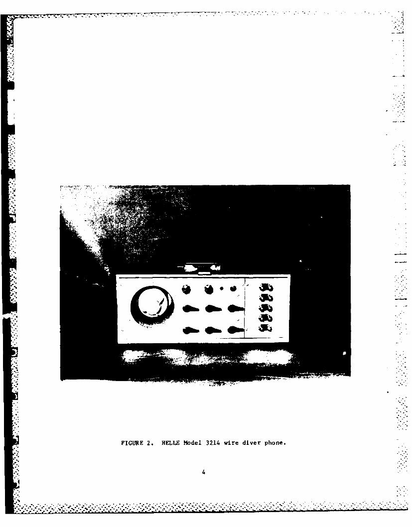
FIGURE 2. HELLE Model 3214 wire diver phone.
. . . . . . . ......... ................

6M' 0. 0 Aj
0 04 -.4 cf *WI ct4 O(.J 0-
.. 4 0 4 *
J 4 0n
0V4 to
04 to' C -04
.)'4a N 3t 0 r
4b4 41J 01C
C1'.4J 0
00
oj G-4 N 41
w-4w04 -
-4 40'.
C-4 4
E-4 0. 4 1 4.1
1w,@.. 0 CJ 41i~
-44 . 8r U
-4 -# 4-
-4 0a 0x0% 0 Io A 0
N- 0-4 Q) :' ~ r.
C'I 0 en I CO
(a
w ae >4 -4
-4010 :.~~~00'CL In-~J '

00
W wzz Iz
0 0
CC
w w0 > c2
- - -
Ir Q
ow w-J Z
ZZ- i -.
I- L7
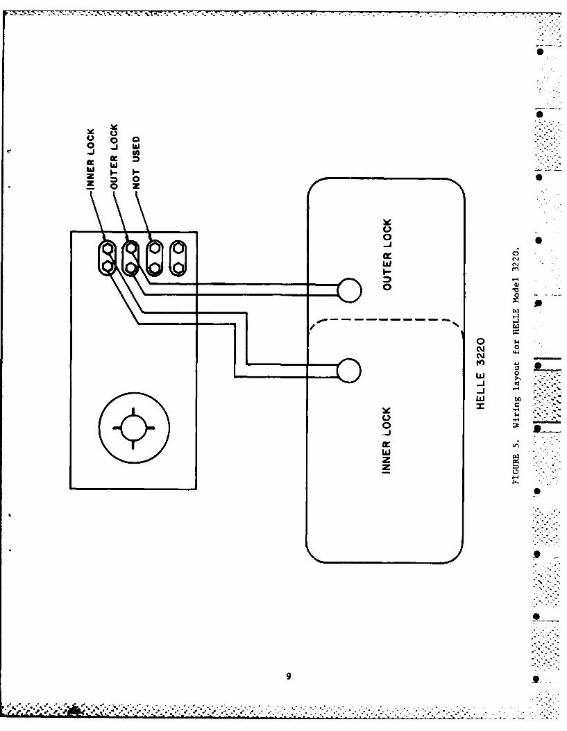
BELLE Model 3220 Wire Diver Phone. The HELLE model 3220 wire diver phone(Figure 4) is an intercom system between a surface tender and either one ortwo divers (in this case personnel inside the recompression chamber, inner orouter lock) at the same time or individually.
Specifications for the
communicator are shown in Table 2.
The system was packaged in an ABS plastic case with a flat cover of thesame material. The front panel was aluminum with silkscreen markings and allconnections were made on the front panel. The system as tested was powered bytwo internal lantern type 6 VDC batteries connected in series to provide12 VDC to the system. There was a low voltage indicator light on the frontpanel that illuminated when the system voltage dropped below 7 VDC. Thecabinet speaker functioned as both a speaker and a microphone; speakers insidethe test chamber provided the same dual function. The system was used in thetwo wire mode (see Figure 5 for wiring layout).
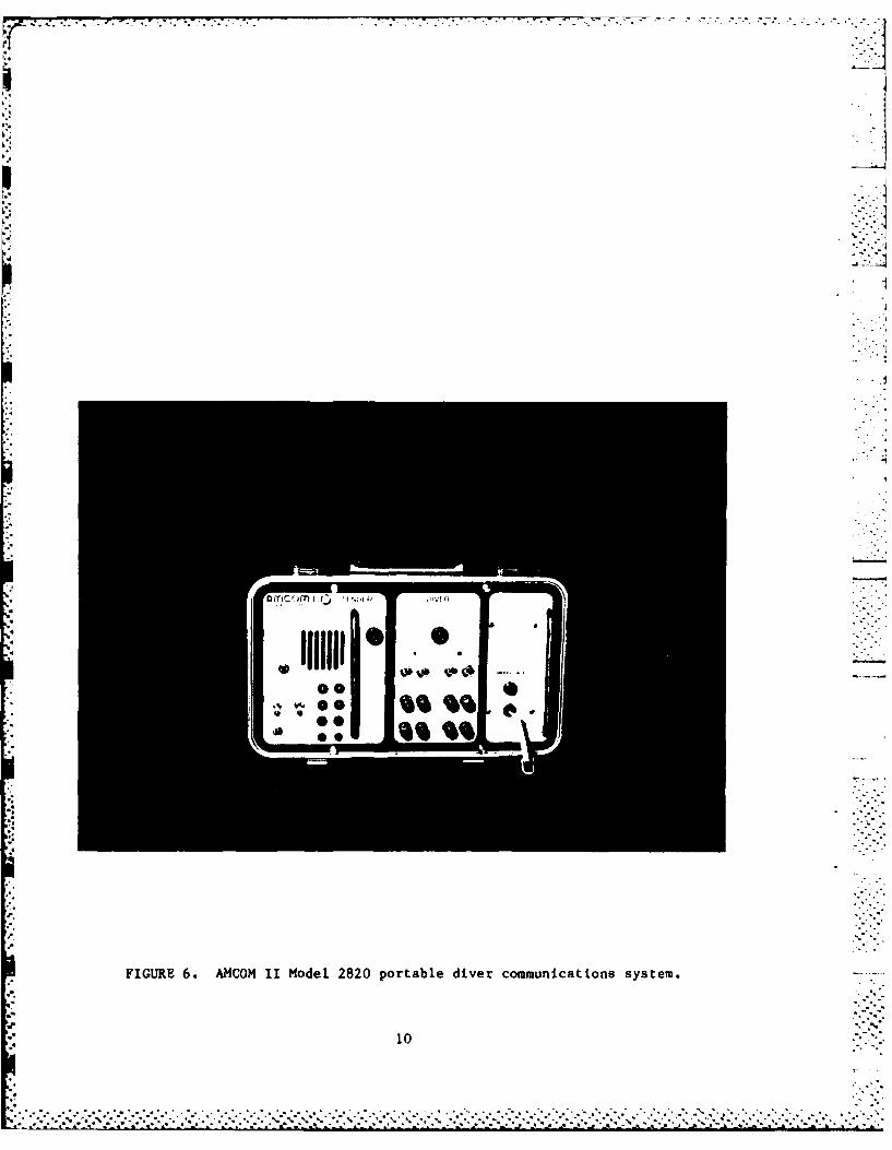
AMCOM II Model 2820. The AMRON International AMCOM II model 2820 (Figure 6)is a portable diver communications system (tested as a chamber intercom) thatoperates from internal batteries or an external 12 VDC power source. Thesystem tested had an internal rechargeable battery and could be operated on a110 VAC power supply. The A.C. power feature was not used during the chambertest but was tested during the bench test. The system was contained in afiberglass case with a detachable cover made of the same material. The frontpanel was aluminum with silk screen markings. All connections were made onthe front panel. The system was tested in the two wire mode; see Figure 7 forthe wiring layout. Specifications for this communicator are listed inTable 2.
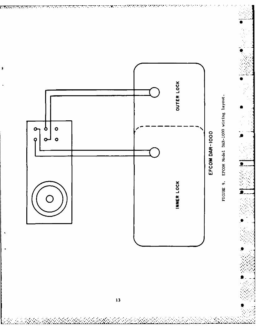
EFCOM Model DAR-1000 Diver Air Radio Communications System. The EFCOMDAR-1000 Diver Air Radio (Figure 8) is a communications system (tested as a ' -
chamber intercom system) that provides two-way communications from a surfacetender to one or two divers. During this evaluation, it was used with theinner and outer locks of a recompression chamber. The speaker on the front ..__panel served as a speaker and microphone and in this test scenario thespeakers inside the chamber also served dual functions. The system waspowered by two 6 VDC batteries contained in a compartment that had a separatecover placed on top of the system container. The container was constructed offiberglass, with the protecting battery cover and the main cover also madefrom fiberglass. The front panel was aluminum with silkscreen type markings.The system was tested in the two wire mode; see Figure 9 for the wiring
. layout. Specifications for this communicator are listed in Table 2.
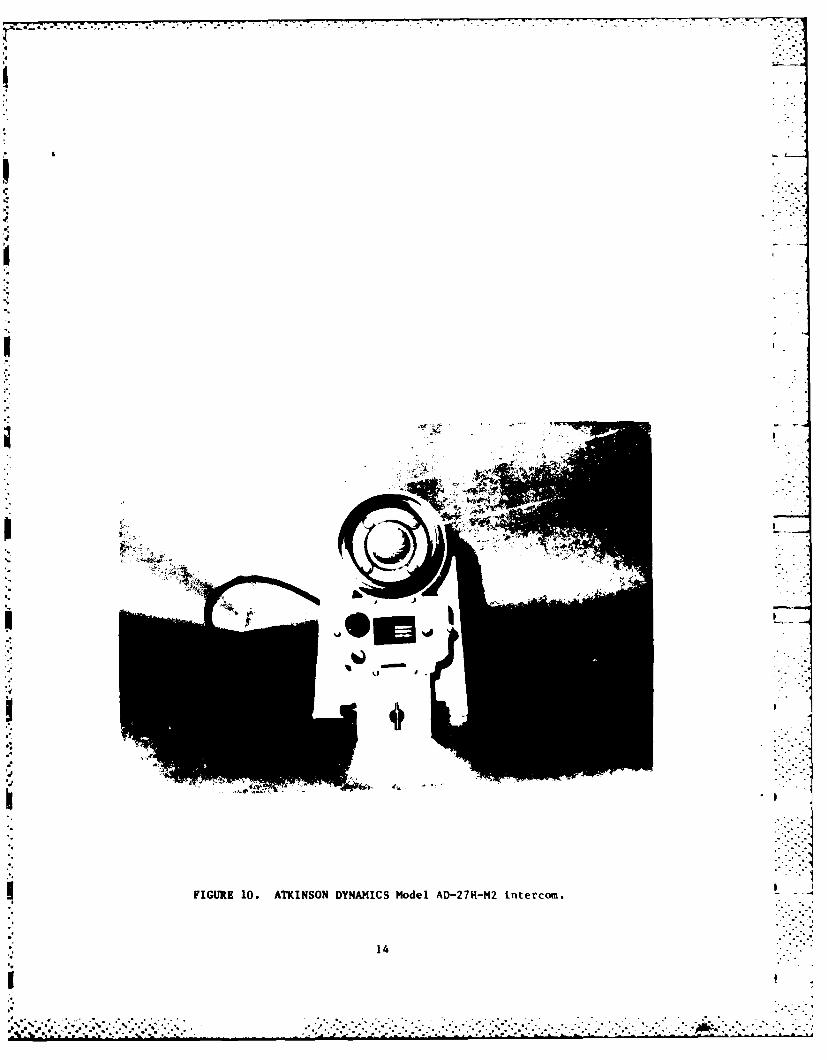
ATKINSON DYNAMICS Model AD-27H-M2. The ATKINSON DYNAMICS Model AD-27H-M2intercom (Figure 10) is a modified industrial intercom built and furnished toDixie Chamber Co. for use as a chamber intercom. The system as testedoperated on 115 VAC power that was internally reduced and rectified to 12 VDC.The system was housed in a cast aluminum case, and the front panel wasconstructed of the same material with engraved markings. Connections weremade at the bottom of the panel. This system was not portable, and was builtto be mounted on a bulkhead or in an upright position. The speaker serveddual functions as a microphone and speaker. A small interface box with aswitch and plugs was built by the test facility in order for the system to beused on the test chamber. The recompression chamber's internal speakers wereconnected to this interface box and also served dual functions as microphone
* 7
52%*..

- . --. . . .-.- . - -
S
p
0. -
*
FIGURE 4. KELLE Model 3220 wire diver phone.
8
.......................................................................................
."%.*. ***%*.*......* -. .. .. . .--------. . . .
P J *.*~~'*.i. Si~.... - . .~
S
U 00~I I&lU)
0
C)0 S-J
0
(N(N
I.--4
________ 0 w__________ 'I
~
rz.i
/
0 1.iNN
_______ 0
-I ~
wz .-..'-4 ... -.(~) S.' *.
d.(1i1)hh. 0 '-4 ____
.4U,
wzz
'-4
0
.9
0
g .9
C ~ . . . . .
V ~ ... . . . .
.-... * *.**.-**'.*.***.*.*.. *. -. . .'-..- . .... .. .
7 7. 7. .
"r
I00
4.0
FIGUE 6 AMOM I Mdel 820porabl dier cmmuicaion sytem
10I

- . .
I
I
V
I00
4J,I-.0 - -
o Cu I______ -4
cc
4.4
- '~~*%% ~
N 0
________ ~ IN e.~
-4ILl ~o
0o'-4
- 4-4~ L
-:
________ ~ L..0
_______ 4-4U0
__ 4%z2
I
11
I-
. .
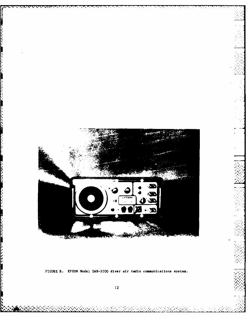
FIGURE 8. EFCOM Model DAR-1OOO diver air radio communications system.7:
12*4**
'do . .*'% *$-:K K *~ K:~ .-4 . . . >. :. .- x.- . . . .x- .. : n .:*. *.
I
0- 0
UU
00
o --
-4
ww
13-
I
I
I
4.
I I
I .- I
I
I I
4'
I FIGURE 10. ATKINSON DYNAMICS Model AD-27H-N2 interccui.
14
I 9
d* * 4. .. -. . . 4
S. .. 4.........4*...*
4. .4 4 . .4.* 4 4 4 4 . . 4.4 . 4 4 4 .
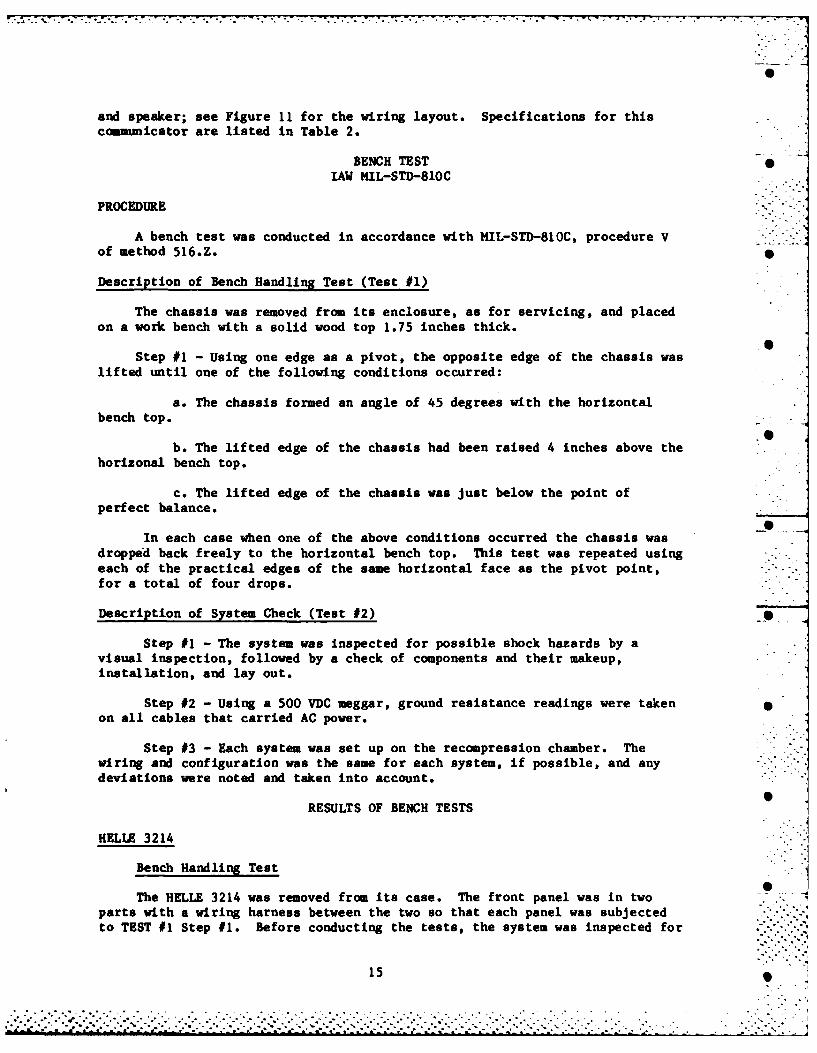
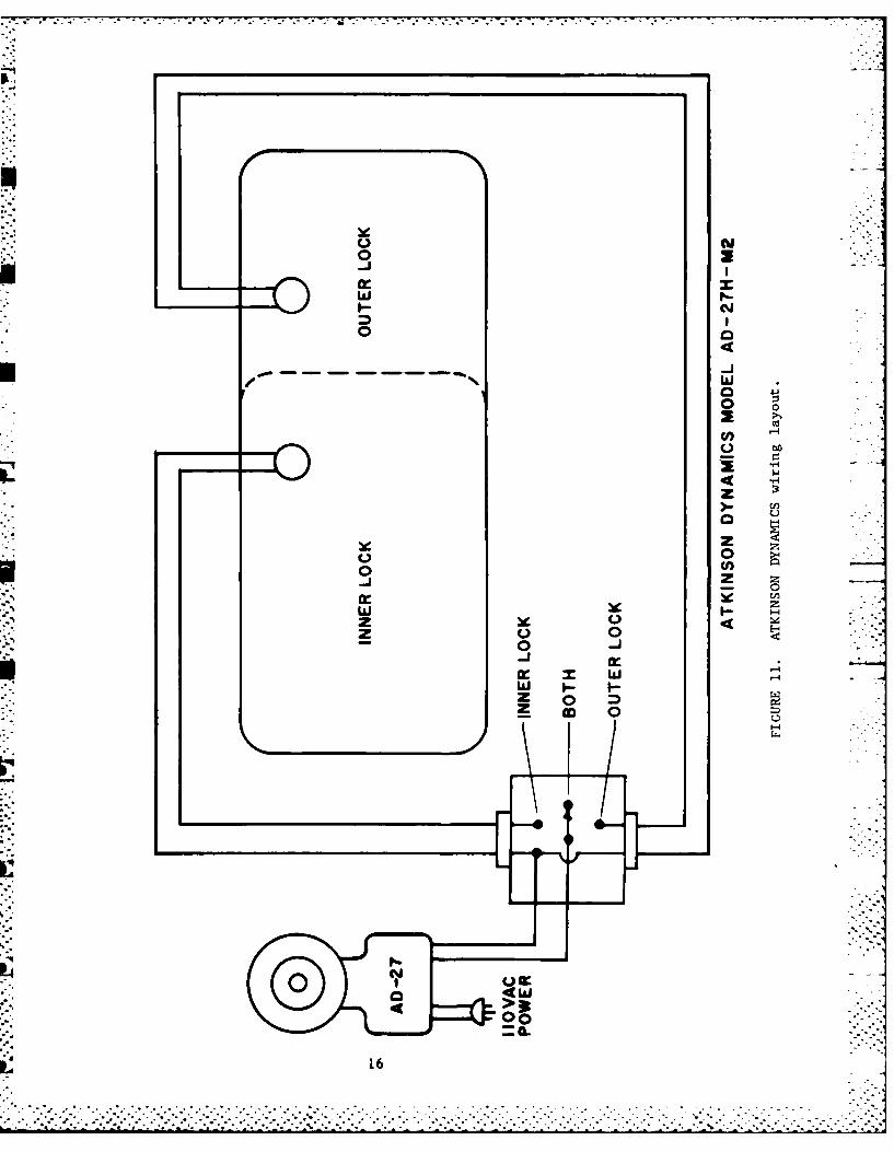
and speaker; see Figure 11 for the wiring layout. Specifications for thiscommunicator are listed in Table 2.
BENCH TEST •IAW MIL-STD-810C
PROCEDURE
A bench test was conducted in accordance with HIL-STD-810C, procedure Vof method 516.Z.
Description of Bench Handling Test (Test #1)
The chassis was removed from its enclosure, as for servicing, and placedon a work bench with a solid wood top 1.75 inches thick.
Step #1 - Using one edge as a pivot, the opposite edge of the chassis waslifted until one of the following conditions occurred:
a. The chassis formed an angle of 45 degrees with the horizontalbench top.
b. The lifted edge of the chassis had been raised 4 inches above thehorizonal bench top.
c. The lifted edge of the chassis was just below the point ofperfect balance.
In each case when one of the above conditions occurred the chassis wasdropped back freely to the horizontal bench top. This test was repeated usingeach of the practical edges of the same horizontal face as the pivot point,for a total of four drops.
Description of System Check (Test #2)
Step #1 - The system was inspected for possible shock hazards by avisual inspection, followed by a check of components and their makeup,installation, and lay out.
Step #2 - Using a 500 VDC meggar, ground resistance readings were takenon all cables that carried AC power.
Step #3 - Each system was set up on the recompression chamber. Thewiring and configuration was the same for each system, if possible, and anydeviations were noted and taken into account.
RESULTS OF BENCH TESTS
HELLE 3214
Bench Handling Test
The HELLE 3214 was removed from its case. The front panel was in twoparts with a wiring harness between the two so that each panel was subjectedto TEST #1 Step #1. Before conducting the tests, the system was inspected for
15
:j-.- ........ ,.......°........,,....., ... , ........................... •,•..........,.... .......
o 1 o
o 0 044
wwo 0
L 4w>z000
16 >
any visual problems, broken wires, loose components, etc. None were apparent.The system was powered up and the output signals checked. Then TEST #1, Steps#1 and #2 were conducted. Upon completion of this phase of the evaluation,the system was again visually inspected for loose components, broken ordamaged wires, etc. None were apparent. Once again, the system was energizedand output signals checked out satisfactorily. During the visual inspectionof the system, it became apparent that some of the key component part numbershad been removed and that part numbers listed in the manual did not agree withpart numbers on the components (i.e. the Printed Circuit Board). The lowvoltage indicator light also came on when the system was moved or subjected tothe slightest vibration while energized. The voltage of the batteries waschecked and found to be 12.3 VDC. The low voltage flasher circuit was part ofthe Printed Circuit Board (PCB) and the wiring diagram provided with thesystem did not cover the PCB. Consequently, no further troubleshooting wasattempted. The system was placed back in its case with fresh batteries. Thesystem was not difficult to remove or replace into its case, although there . •
was one screw located behind one of the cross talk switches (DV 1 & 2).
System Check Test
The internal layout was such that troubleshooting of components would bevery difficult. The wiring diagram and parts list indicated one part numberon the Printed Circuit Board while the PCB in the system had another number.The wiring diagram provided with the system would also be of little value inrepairing the system.
There appeared to be no shock hazards either to the operator, diver orrepair personnel. This system, as provided, was powered by batteries with noA.C. power input so ground resistance readings were not taken as part of thistest. The system was checked for compatible hook-ups with the test chamberand no alterations were needed in order to conduct the test as planned.
HELLE 3220
Bench Handling Test
The HELLE 3220 was removed from its case. The front panel was in twoparts, one of which was the battery compartment cover that was held in placeby a lip on the right side and a thumb screw on the left. The main frontcover was held in place with six screws, all of which were easily removed. 0All of the internal components were attached to the main front panel exceptthe batteries to power the system.
Before conducting the bench tests, the system was inspected for anyvisual damage, i.e. broken wires, loose components, corrosion, etc. None wereapparent except for a problem with the batteries which were in the system when Sit arrived at NEDU. They were badly corroded and discharged. New batterieswere connected and the system was powered up and the output signals checked.Then the batteries were disconnected and TEST #1, Steps #1 & 2 were conducted.Upon completion of this phase of the evaluation, the system was visually -
inspected for loose, broken or otherwise damaged components. None wereapparent. The system was again energized and output signals checked outsatisfactorily.
17
-. ---. .

System Check Test
Key components on the PCB had identifying markings removed, thushindering any repairs by users. Also the wiring diagrams provided with thesystem were for the most part unreadable and of little value as atroubleshooting aid. However, the component layout was simple and most of thecomponents were easy to access. The system as tested was battery poweredalone with no A.C. inputs so ground readings were not taken. The system waschecked for compatible hook-ups with the test chamber and no alterations were -needed in order to conduct the planned test.
AMCOH II Model 2820
Bench Handling Test
The AMCOM II system was removed from its case. This was accomplishedvery easily as only four thumb screws held the system in its case. However,they were placed at points that hold the system in place evenly. After thefour thumb screws were removed there were two handles provided to lift thesystem from its case. Removal of the batteries was not difficult but someresistance was experienced with one of the batteries because it rubbed theback of the speaker driver as it cleared the battery compartment. Beforeconducting the bench tests the system was inspected fuc visual damage and nonewas apparent. The system was powered up and output signals verified. Powerwas then secured and TEST #1, Steps #1 & 2 were conducted. Upon completion ofthis phase of the evaluation, the system was again visually inspected forloose, broken or otherwise damaged components. None were detected. Again thesystem was energized and output signals checked out satisfactorily.
System Check Test
The system was visually inspected for possible shock hazards and nonewere apparent. A check of component layout, make up and installation was madeand found to be satisfactory in all respects. Along with the physical checkof the system a comparison between the parts lists, drawings and actualcomponents was made. The results were that the parts list and drawings werevery good with no discrepancies between the software and the actual hardware.The manual would provide the necessary guidance for user maintenance to beconducted by U.S. Navy personnel with an electrical background.
Using a 500 VDC meggar, ground resistance readings were taken on the A.C.power lead with the proper readings recorded. Following the bench tests, thesystem was placed back in its case. No configuration changes were required inorder for the system to be tested on the recompression chamber.
" EFCOM DAR-1000.
Bench Handling Test
The EFCOM DAR-1000 system was removed from its case. This wasaccomplished by removal of six screws from the face, each having lock nuts onthe back lip of the case front. The was followed by removal of four more
18
. . . . *. .. .% •.-
. , , ': , ; .. ' .'- -. .. "." . -'. " .... '-'. .. '.'....'..'.. .'.... -....-..... ... . .. ....-... . .. . . .. .... .. .. .. . - .- . .. '
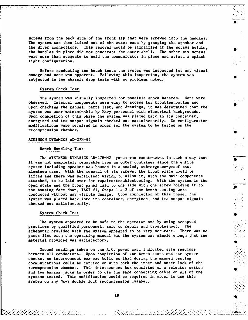
screws from the back side of the front lip that were screwed into the handles.The system was then lifted out of the outer case by grasping the speaker andthe diver connections. This removal could be simplified if the screws holding 0the handles in place did not penetrate the outer shell. The other six screwswere more than adequate to hold the communicator in place and afford a splashtight configuration.
Before conducting the bench tests the system was inspected for any visualdamage and none was apparent. Following this inspection, the system wassubjected to the chassis drop tests with no problems noted.
System Check Test
The system was visually inspected for possible shock hazards. None wereobserved. Internal components were easy to access for troubleshooting and
upon checking the manual, parts list, and drawings, it was determined that thesystem was user maintainable by Navy personnel with electrical backgrounds.Upon completion of this phase the system was placed back in its container,energized and its output signals checked out satisfactorily. No configurationmodifications were required in order for the system to be tested on therecompression chamber.
ATKINSON DYNAMICS AD-27H-M2
Bench Handling Test
The ATKINSON DYNAMICS AD-27H-M2 system was constructed in such a way thatit was not completely removable from an outer container since the entiresystem including speaker was housed in a sealed, submergence-proof castaluminum case. With the removal of six screws, the front plate could belifted and there was sufficient wiring to allow it, with the main componentsattached, to be laid over for repairs/troubleshooting. With the system in theopen state and the front panel laid to one side with one screw holding it tothe housing face down, TEST #1, Steps I & 2 of the bench testing wereconducted without any visible damage. Upon completion of this phase, thesystem was placed back into its container, energized, and its output signalschecked out satisfactorily.
System Check Test 0
The system appeared to be safe to the operator and by using acceptedpractices by qualified personnel, safe to repair and troubleshoot. Theschematic provided with the system appeared to be very accurate. There was noparts list with the operating manual but the system was simple enough that thematerial provided was satisfactory.
Ground readings taken on the A.C. power cord indicated safe readingsbetween all conductors. Upon completion of the bench tests and the systemchecks, an interconnect box was built so that during the manned testingcommunications could be carried on with both the inner and outer lock of therecompression chamber. This interconnect box consisted of a selector switchand two banana jacks in order to use the same connecting cable on all of thesystems tested. This modification would be required in order to use thissystem on any Navy double lock recompression chamber.
19

,qg -,,,-- .- - . . . .- . 'a . .- .7 ' -. ' . . . - . ,-. -'- " "-" - .
Summary of Bench Test and Evaluation Checks
While all of the systems were found to have some discrepancies, all werefound to be safe to operate as designed. The most significant problems werefound to be in the area of maintainability, i.e. troubleshooting and repair inthe field by Navy Technicians. The Helle models 3214 and 3220 both hadshortcomings in this area in that there were several key components that wereunidentified because their markings had been removed. Further, the ellemanuals were incomplete and inaccurate, and the system schematics weredifficult to read.
The Atkinson Dynamics System did not come with a manual; a Sales andSpecification sheet and a package of System Drawings/Schematics accompaniedthe unit. However, there was sufficient material to troubleshoot the systemand make repairs if necessary. The AMRON and EFCOM Systems both wereaccompanied by very good manuals, drawings and schematics. Included in bothpackages was a complete parts list. The Atkinson Dynamics AD-27H-M2 was theonly system that had to be modified in preparation for the manned test on therecompression chamber. This modification, previously described in the text ofthis report, would be required on U.S. Navy double-lock chambers.
During the course of testing, only one system, the elle 3214,experienced a failure. The failure is described elsewhere in this report.The other systems proved reliable during the limited time each wasoperational. In particular, the AMRON model 2820 and the EFCOM DAR-1000 wereaccompanied by very good reference literature. Workmanship was of highquality in these two systems. These features are good indications of areliable product. Lastly, linked to the concept of reliability is the lifecycle cost of each system. Based on the purchase price of each system and thereliability exhibited during this evaluation, the AMRON model 2820 and theEFCOM DAR-1000 should have the most favorable life-cycle costs.
HUMAN FACTORS EVALUATION OF SYSTEM CONTROLS
Procedure:
A human factors evaluation of each communication unit was undertaken toassess the areas of control coding, control designation, control resistance,control location and control feel. These areas influence operator efficiencyand accuracy, which in turn effects the efficiency of the communication systemand the safety and performance of the chamber occupants. For a furtherdiscussion of the principles of control design, the reader is referred toVan Cott and Kinkade (1972).
RESULTS
The following observations were noted for each unit:
HELLE MODEL 3214
Coding and Designation
(1) The "press to cross connect" switch label was under theappropriate switches, whereas the "press to talk" labels were placed abovetheir respective switches, resulting in non-conformity of label positioning.
20
.............. " . .. -..... ......- ......... ..........*t -d , . * . i . * * . . o . . * . . . . . . .. . . . . . * . .
-. . . . ...-. .-.
(2) "Diver 1 to" label was not adequately grouped near the bottomlegends; the lettering should be closer to "Divers 2 and 3".
(3) The black 3mm high coding letters showed up well on the silver 0gray background.
(4) There was no directional indication on the diver's volumecontrol.
Location Variables •
(1) The "press to talk" toggle switch was in the upper right handcorner. As this is the most frequently used control, it should be locatedcloser to the speaker because it is activated when the person talks into thespeaker.
(2) Volume controls were grouped together nicely, as were the "pressto talk" and "press to cross connect" levers.
(3) The hardwire inputs were appropriately labeled.
(4) The physical spacing between the adjacent "press to talk" leverswas less than the minimum required in the horizontal plane. Minimumrecommended distance is a 5.8 cm radius around a control (Van Cott andKinkade, 1972); actual radius was 4.6 cm between adjacent levers. Theoperator's fingers (e.g. middle finger) contacted adjacent levers when usingthumb and forefinger operation.
Resistance and Feel Characteristics
(1) None of the press levers provided indication of positiveactivation. All press levers required 2 finger operation with no positivedetent on these controls. A "grating" resistance was felt by the operator.
(2) The "press to talk" toggle switch provided good positivefeedback to the operator via a detent and was covered to prevent dirt andmoisture contamination. One finger was all that was required to operate thisswitch.
(3) The "tender volume" knob had a positive on-off action. The
"divers volume" knob had no positive detent, but positive stops. When thesevolume control knobs were placed in the fully open position, three operatorsreported that the knobs were in the "off" position.
HELLE MODEL 3220 9
Coding and Designation
(1) The speaker toggle switch did not have an "off" label.
(2) Color coordinated plug inlets were provided for the 12 VDCexternal power source. .
21I
!' . .._.,_." - ,/ . ',.-...-.. .. --..... -".... ......-....-"..".-"...-".--..".- .-"- ...'.."- .-.---..--".-..... ".".-..-.

• . . _.
location Variables
(1) The "press to talk" lever position and that of the "cross talk"lever were suitable only for a right-handed operator.
(2) The "press to talk" lever was physically located too close to
the "cross talk" lever.
(3) The "cross talk" lever was located too close to the hardwire
inputs. Operation of this lever also required two fingers, and the operator'shand would cover, rub against, or interfere with the hardwire input entry.Cuts and abrasions to the hand may result.
Resistance and Feel Characteristics
(1) There was no positive evidence of actuation (e.g. detent) whenoperating the "press to talk" lever.
(2) The "cross talk" lever provided just discernable audio andtactile feedback. However, each lever on the unit tested provided differentpoints of feedback dependent upon whether the operator was pressing orreleasing the lever.
(3) The "speaker" toggle switch provided a good detent for feedbackto the operator.
(4) The "tender volume" knob had a positive on-off mode and stops.
(5) The "diver volume" knob did not provide positive on-offfeedback, but did provide a positive stop.
(6) The "press to talk" lever had excessive resistance for singlefinger operation. Should the operator attempt to use two fingers, the wristof the operator will be placed in a strained, awkward position.
AMCOM II MODEL 2820
Coding and Designation
(1) This unit incorporated good grouping of diver and tendercontrols by using black colored bands for separation.
(2) Directional indications and on/off codes were not provided onthe tender and diver volume controls.
(3) The diver "push to talk" switches labeled "on" and "off" weresomewhat misleading because on the tender side the switch with the samefunction was labeled "push to talk".
(4) "Push to talk" switches are more appropriately labeled "depressto talk".
22
... .......... . . . .. . -. . .... ..

*2 .1 .7- .D .. .. =.. . .. :: =r : - - .. :-. ...... --< "- ' " : - -"-.
Location Variables
(1) To activate the diver crosstalk momentary switch, the operator'shand rested against the hardwire input/output connections, raising the spectreof injury to the hand and displacement of wires.
(2) The diver crosstalk controls were placed non-sequentially in ahorizontal row (i.e. on-crosstalk-crosstalk-on) rather than in a sequentialfashion (i. e. on-crosstalk-on-crosstalk). The present configuration wasconfusing.
(3) The "power on", "speaker on", and "push to talk" switches on thetender panel were all in the same location, of the same configuration, and invery close proximity to each other. Control confusion and inadvertantactivation by the operator are a distinct possibility.
(4) The carrying handle on the tender side of the unit was
imediately adjacent to the microphone. This physical obstruction couldresult in decreased or altered sensitivity, and also interfere with theoperator's line of sight for the wiring labels.
(5) Placing the front AC plug on the lower right hand sidenecessitated a connection with a power supply in an exposed position.
Resistance and Feel Characteristics
(1) All toggle switches had positive feedback and required onefinger operation only, with a positive return action on the "push to talk"switches.
(2) The volume controls had no positive on-off detents. However,they did have positive stops and were easy to rotate with thumbs andforefingers.
(3) Finally, a right handed operator must talk over his right armand into the speaker when operating the "push to talk" switch in the tenderpanel.
EFCOM DAR 1000
Coding and Designation
(1) The panel face was blocked off by blue and black lines, but wasnot grouped either by function or components. The layout of the controlsappeared arbitrary and the graphics were for aesthetics alone.
(2) "Push to talk" switches should be labeled "depress to talk".
(3) The label for "diver speaker" located above the diver selectorknob was the same letter height and distance from the control knob as were thefunctioning labels. The labeling used did not discriminate selector positionfrom selector label.
23

- --- 7 7 . . . .- .2 . .
(4) The "Crosstalk" label was difficult to read in the verticalplane. The placement of the crosstalk labels (i.e. "Diver 1 to 2", "Diver 2to 1") were equidistant or closer to the hardwire inputs than to theirrespective crosstalk switches. 0
(5) The diver volume controls had no "on" or "off" labels. -' -.
(6) The EFCOM signature label and graphics take up considerablespace which could be used for functional operations.
S
Location Variables
(1) There was good spacing between the tender volume and diverspeaker rotary knobs.
(2) Inadequate spacing existed between the diver volume knob and the Searphone hardwire input.
(3) The crosstalk switches and the push to talk switches were ingood position concerning clearances for the operator's hand.
Resistance and Feel Characteristics P
(1) All toggle switches had a positive detent and provided feedbackto the operator.
(2) The crosstalk toggle switches were of different colors and indifferent locations. However, the horizontal activation of switches wasunusual and may cause confusion and/or breakage.
(3) The tender volume knob had a positive "on-off" detent, whereasthe diver volume knob had no positive "on-off" detent. Further, the graphicsdid not indicate the position of full on and full off, and there appeared tobe excessive rotation of the knob (approximately 80% full circle).
(4) The "push to talk" toggle switch required excessive force toactivate and keep depressed.
(5) The crosstalk toggle switches will generally call for two fingeroperation (thumb and forefinger) and require a strong force to operate. S
(6) Dust covers on the toggle switches and spring covers on themicrophone and headset were good protective devices.
ATKINSON DYNAMICS AD-27H-M2
Coding and Designation
(1) This unit had silver letters, 4 - high, etched into the consoleface. These letters (labels) were located above their respective controls.
(2) The "power" and "audio" labels should have a directional arrowbeneath each label pointing to where the cables enter the unit.
- -'.
e-o oo~e..'.t. .o.°. . . ..°..o 'oo .o o o• - . .. '. . -. .. - . - . .... .. .... .°. . 'o o •
(3) There was no "on-off" indication or labeling to direct theoperator how to turn the unit on or off.
(4) No arrow indicator or pointer was furnished on either the, "local" or "remote" volume knob to indicate control setting and/or direction.
Location Variables
(1) The toggle switch for "talk" was centered on the right side ofthe console in a good position for right-handed operators.
(2) Both volume knobs were located on the left side of the console,grouped nicely, but closer together than optimally desired (5.8 cm radiusdesired; 3.5 cm radius obtained).
. (3) A clean, uncluttered console face was provided.
Resistance and Feel Characteristics
(1) The "listen-talk" toggle switch had a faint positive detent anda protective dustcap.
(2) A positive on-off detent and stop was provided for the localvolume knob.
(3) The remote volume knob had no positive on-off detent.
SUMMARY
To varying degrees all units reflected their manufacturer's efforts atcontrol coding, location and activation. As was evident from the results ofthe human factors evaluation, however, all units fell short in several areas.Inadequate spacing between controls, inappropriate labeling, lack of positivefeedback on controls, and failure to protect the operator's bare hand fromaccidental cuts and scrapes were the most prevalent discrepancies noted. Allof the documented human factor control discrepancies appear to be easilycorrectable by the manufacturers with careful prior planning design. Mostimportant, no human factor control discrepancies were noted on any unit whichwere serious enough to warrant a unit failing this portion of the evaluation.
OPERATIONAL MANNED TESTS
PURPOSE
This portion of the evaluation was conducted to test the communicators in
the actual environment in which the communicators would be used.
METHOD
Subjects
One female and five male U.S. Navy divers, all volunteers and in goodhealth, served as test subjects. Auditory acuity levels of all diver-subjects
25 .A5
S.''' -' / .. ,""V ""' "''''"- ', ",.".-". .". ".." ,---" " .- " " .'-,'-'. ' . .".."... ' '

as assessed by an audiogram within the last nine months were within limitsoutlined in Article 15-11 of NAVMED P-117. Subjects did not exhibit anynoticeable articulation problems, unusual dialects or speech deficits.
Intelligibility Test [Modified Rhyme Test (MRT)]
Following the guidelines set forth in NEDU Test Plan 83-28, each of thetest communication systems was set up on a double lock recompression chamberwith three listeners on the inside of the inner lock of the chamber and threelisteners on the outside. Close attention was paid to insure that listenerswere sitting in the same location for the tests conducted on each system.These tests were conducted twice on each communication system at each of thefollowing depths: 0, 60 and 165 feet of sea water (FSW). Twenty-five wordswere read from the MRT word lists vice 50 words to minimize overall bottomtime and decompression time for the divers. A sample MRT is included inAppendix A.
Procedure
All divers wore flame-retardant clothing and were seated side-by-side indesignated places inside the chamber. Each diver carried a clipboard and aMRT response or reading sheet as appropriate. Diver and outside operatorlocations were set in the same position for each test, with the readers of theMRT always in the center position. Positions are shown in Figure 12.Speakers were rotated 1-2-3-1-2-3 on each dive team. Communicator tests weresequenced to ensure that no communicator immediately followed anothercommunicator on both trials. The volume of both the inside anx4 outsidespeakers was adjusted to the listeners' preference before each test started.The carrier sentences containing the designated MRT words were delivered atthe rate of one every five seconds.
Interior and exterior chamber lighting was kept constant, as wascommunicator placement on a desk outside the chamber and operator seatpositions. The area around the chamber was kept clear, and control wasexercised over noise sources such as talking, door slamming, etc. to preventdistractions and loss of data. Identifiable, uncontrolled noise sources thatoccurred during testing included intermittent telphone ringing, elevatoroperation, paging over an intercom, operation of gas compressors in anadjoining facility, and occasional helicopter landings 200 yards away.
Compression of the chamber on air was accomplished at a rate of 75 feetper minute to depths of 60 and 165 FSW. Testing was conducted at 165, 60 and0 FSW. The chamber was ventilated upon reaching each test depth beforetesting started. A carbon dioxide scrubber was running during compression and jdecompression, but not during testing. During each test, the reader and onelistener on the outside team filled out a questionnaire on the communciatorthey were using. The standard internal transceiver (speaker) was used insidethe chamber in all cases. These transceivers serve a dual function as amicrophone for transmitting and as a speaker for receiving. The transceiversused had a value of 8 Ohms at the communicator system. "
26
.... °. . . ................. .. ........ * . .. .. . . .. . . . .
%°% ... . . . . . . . . . . . . . ..'*o.''.°"....*o.* • . - .- ,. .. ° . • .. .' ...... " ...-.. . ,. ".-*. . . . . . . . . . . . . . . . .. . .oO ' '',,"_,"."J '.... .. _."_," :_."-..._."."."."_.- /_-' -'--'.,". : -:."."..".... ..- ",,..._... . ... ...... . .- "-.-.. .-.- "-.-.-'.-.-. .-. ."-'- -- ". .- '-.-

0
S
0
4.10
-40
a,a,4.1
*1*4ha
*0
-.44.1-. 4S
00.
ha0'a0haa,0.0
a,
-4S4.1
o
0
haa,
.2CI
'-4
1
S
27 ft
- . - . . .......... i. -*..*..*.*v*..*.~..*..*..*. **I*.~.~ *.~ . **~**~II.****~.~.....

.i
Results
The formula used for scoring the MRT was: Z correct =(no. right- n o. wrong) x 4. Temperature ranges inside the chamber during
testing (and after venting) were as follows: 0 FSW (70-78"F); 60 FSW(72-82°F); 165 FSW (78-87"F). " .,
Four of the five communicators met or exceeded the minimal acceptableintelligibility score of 75% for the MRT as set forth in MIL-STD-1472B; theHelle 3214 did not meet this criteria. The following overall speech
intelligibility scores on the MRT were recorded for each system: Helle
3214-62%; Helle 3220-86%; AMCOM 11-80%; EFCOM 1000-84%; AD-27H-M2-77%.
A two-way repeated measures analysis of variance (Myers, 1972) wasconducted to determine the significance of the differences among the meancorrect word scores recorded by communicator units on the MRT. Significantdifferences among communicators were found IF(4,20) - 12.76, p <.011, as wellas among test depths IF(2,10) - 12.42 < (.011.
Subsequent tests were performed among the means using Duncan's MultipleRange Test (Bruning and Kintz, 1968). These tests found that the Helle 3214was significantly poorer overall (p <.01) than any of the other communicatorunits in word intelligibility; none of the other communicators differedsignificantly from each other. A similar analysis was performed on thecombined mean communicator scores at each depth. Significant improvement
(p <.01) in word intelligibility was found between 0 and 60 FSW, and between 0and 165 FSW. There were no significant differences in word intelligibilitybetween 60 and 165 FSW.
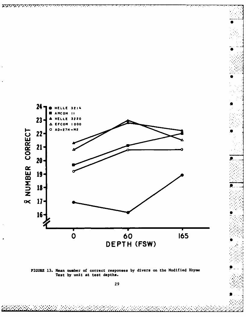
Figure 13 shows the mean number of correct responses by divers on theMRT by unit at the test depths. A significant depth/communicator unitinteraction was present [F(8,40) - 29.02, p <.01]. Whereas the number ofcorrect answers rose steadily for four of five units from 0 to 60 FSW, two of - -
the five units (EFCOM and Helle 3220) showed a decrease in intelligibility asthe depth was increased to 165 FSW. The other units either increased inintelligibility (AMCOM and Helle 3214) or remained stable (AD). It should benoted that the magnitude of the loss of intelligibility was not enough to fallbelow surface levels recorded from these units except for the Helle 3214, theperformance of which was poorer at 60 FSW than at the surface. Correctresponses of all subjects on all communicators were consistently lower whenrecording on the outside of the chamber (2 - 72.6% correct; SD = 12.4%) thanwhen recording on the inside of the chamber (5E - 91.5% correct; SD - 4.4%).
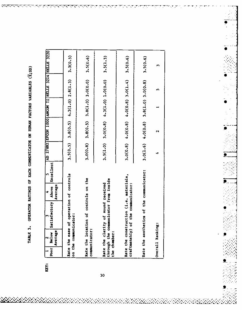
During the manned dives the operators kept a log and two outsidepersonnel completed questionnaires on each unit tested. (See Appendix B for a
.- sample of the questionnaire used). Operator ratings of each unit on humanfactors variables are presented in Table 3. The AMCOM II was rated the bestcommunicator overall on human factors variables by the operators, and alsoscored highest in 4 of the 5 specific areas. The AMCOM II also was ratedsubstantially higher on clarity of sound when compared to all other units.The EFCOM 1000 communicator received high marks in 4 of 5 areas and was ranked
* overall as the second best communicator. The Belle 3220 and the AD-27H-M2ranked third and fourth, receiving satisfactory evaluations on human factors
44 28
gh.* -
_______ ___ .-____ .1
24 0 HELLE 3214
U ANCOM 11
A EFCOM 1000
~22w~210
0U2 0
I)19
16
o 60 165DEPTH (FSW)
FIGURE 13. Mean number of correct responses by divers on the Modified Rhyme 7-Test by unit at test depth.
29
A A-
00
0 0-40% A~
>% 1-4-%0
-4 G
Cd,
Le) 0I -
-n 0 >4 090 > U 0 0 01
-0 01 0 -f4 00 .-4 W
o 0t 41) 0V 0o
t~to00
o0 0 0 0 14
0 01 C u,
go 0 Z04 A
0 93 cosJA
0 0 401 41 ccI4 w41 Au A 4 41
41 U4 00 A- A 410
20 441
300
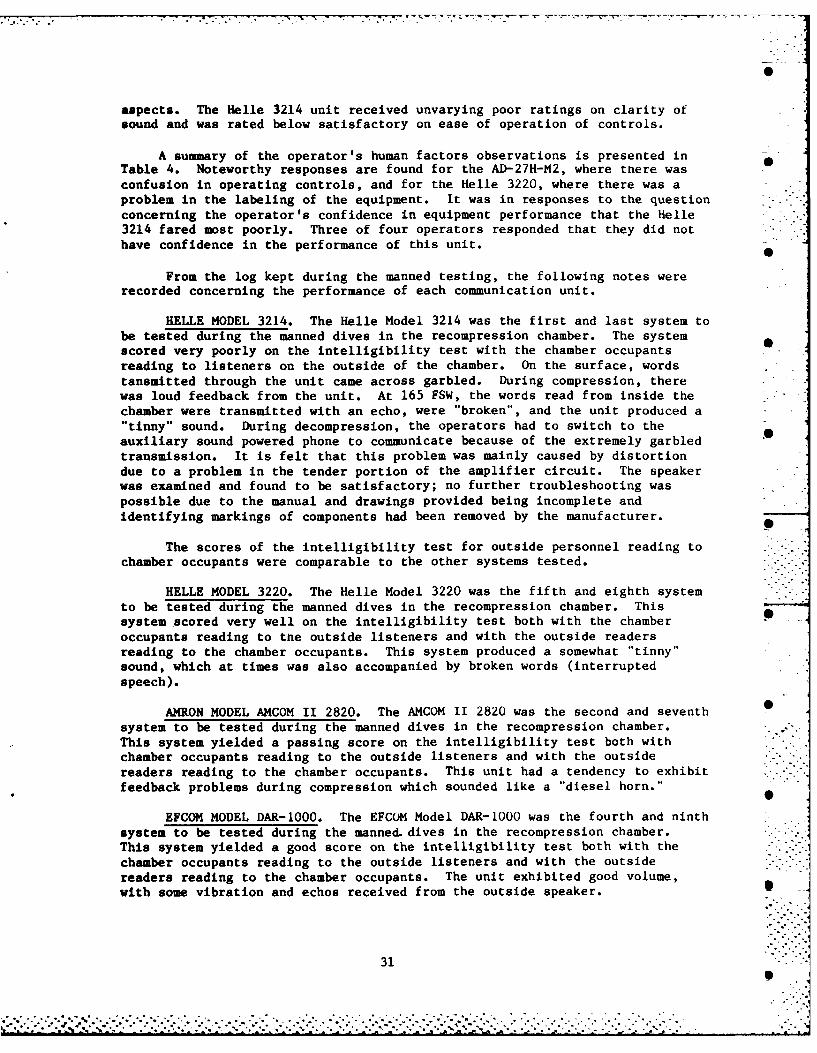
aspects. The Helle 3214 unit received unvarying poor ratings on clarity ofsound and was rated below satisfactory on ease of operation of controls.
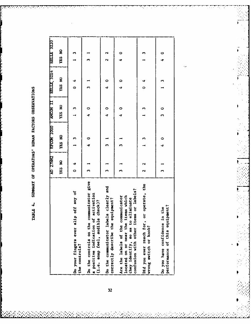
A summary of the operator's human factors observations is presented inTable 4. Noteworthy responses are found for the AD-27H-M2, where there was
confusion in operating controls, and for the Helle 3220, where there was aproblem in the labeling of the equipment. It was in responses to the questionconcerning the operator's confidence in equipment performance that the helle3214 fared most poorly. Three of four operators responded that they did nothave confidence in the performance of this unit.
From the log kept during the manned testing, the following notes were
recorded concerning the performance of each communication unit.
HELLE MODEL 3214. The Helle Model 3214 was the first and last system tobe tested during the manned dives in the recompression chamber. The systemscored very poorly on the intelligibility test with the chamber occupantsreading to listeners on the outside of the chamber. On the surface, wordstansmitted through the unit came across garbled. During compression, therewas loud feedback from the unit. At 165 FSW, the words read from inside the
chamber were transmitted with an echo, were "broken", and the unit produced a"tinny" sound. During decompression, the operators had to switch to theauxiliary sound powered phone to communicate because of the extremely garbled
transmission. It is felt that this problem was mainly caused by distortiondue to a problem in the tender portion of the amplifier circuit. The speakerwas examined and found to be satisfactory; no further troubleshooting waspossible due to the manual and drawings provided being incomplete and
identifying markings of components had been removed by the manufacturer.
The scores of the intelligibility test for outside personnel reading to
chamber occupants were comparable to the other systems tested.
HELLE MODEL 3220. The Helle Model 3220 was the fifth and eighth systemto be tested during the manned dives in the recompression chamber. Thissystem scored very well on the intelligibility test both with the chamber
occupants reading to the outside listeners and with the outside readersreading to the chamber occupants. This system produced a somewhat "tinny"sound, which at times was also accompanied by broken words (interruptedspeech).
AMRON MODEL AMCOM II 2820. The AMCOM II 2820 was the second and seventhsystem to be tested during the manned dives in the recompression chamber.This system yielded a passing score on the intelligibility test both with
chamber occupants reading to the outside listeners and with the outsidereaders reading to the chamber occupants. This unit had a tendency to exhibitfeedback problems during compression which sounded like
a "diesel horn."
EFCOM MODEL DAR-1000. The EFCOM Model DAR-1000 was the fourth and ninthsystem to be tested during the manned. dives in the recompression chamber.This system yielded a good score on the intelligibility test both with the
chamber occupants reading to the outside listeners and with the outsidereaders reading to the chamber occupants. The unit exhibited good volume,with some vibration and echos received from the outside speaker.
31S
"% .""°°o .%°
"'"o - ° l .° ." - ° . ". . . . . . . . ...' . - ° o °""'""'-.1 .-"% 0° . . . ..'° ." . -. ". . -, °"-.• •
"
00
E-44 -
>.4
0o
00
.-4
09 1
0 0 0 0 0
0 0% .0 0
> 1-r 4 . 0 .
2 d Qcc 0 cc c -4 0
> W C., C-
0 -i .4 0 4 ' 41
to o3 w C w
10 d 41 q 4
41 0 10 m 44A0q $40 -4 ca000 A..i 01 4104 V
(9 CO~ 4JA 4 040 4J44.
04 0.4.lC V .4. 41 44.0( $ 00 4W V. 0 0 4)' 0 0 O Ow.-%41 l..i
4.4 FA W.44 0 .. 44 0 w14=
0 421 9 4) 41-0~C- 004ccr1A A
44 4 4J0 .0.01 4-0 041 *.4 l4a 4 0 0 41
04.1 041 4 A .041 0 w'. go>% 0 4
0m 4 04u10 0 0.* 0'- w5 0 411..'i
0-4( 441 r~4~ 410 44n
~0 010. 04.1~32

ATKINSON DYNAMICS MODEL AD-27H-M2. The Atkinson Dynamics ModelAD-27H-M2 was the third and sixth system to be tested during the manned divesin the recompression chamber. The system's score on the intelligibility testwas barely passable, mainly due to insufficient volume both inside and outside
the chamber. The entire tests were conducted with the volume controls set onmaximum. All test subjects were observed leaning forward in their seats tolisten to the transmissions, even with minimal background noise present. Goodtransmission clarity was exhibited on the surface, and there was an absence of"squealing (feedback)" noted during compression.
OVERALL SUMMARY AND CONCLUSIONS
The five commercially available hardwire communication systems wereevaluated side-by-side in a series of tests designed to assess theirreliability, operability, safety, and intelligibility. These tests included
bench handling, system checks, human factors assessment of controls,operational clarity, and operator use. No communication system was free from
defects as assessed by the evaluation. However, three systems possesseddeficiencies serious enough to prevent them from being considered for use bythe U.S. Navy. The Helle Model 3214 failed to obtain a minimum acceptablelevel of speech intelligibilty at any depth tested, had key component numbers
removed from the chassis, was difficult to troubleshoot with the limitedinformation provided in the wiring diagram, and did not win the confidence ofthe operators. The Helle Model 3220 also lacked adequate schematics and
information for even the most basic repair functions and thus was notrecommended for use because of the discrepancy. While the Atkinson DynamicsModel AD-27H-M2 system met the minimum criteria for speech intelligibility,the volume of the system was insufficient to carry sound to the operator's
ears at a distance of three feet or more. In addition, modifications wouldhave to be made in order to mount this system to recompression chambers.
Two systems (AMRON Model AMCOM II and EFCOM Model DAR-1000) met all of
the basic requirements outlined in the bench, human factors, and operationalsubtests. The operators rated these two units highest on human factorsvariables, and indicated that they had confidence in the performance of these
units. Both units scored well in the speech intelligibility portion of theevaluation, and came with adequate information for repair and troubleshooting.These two systems should also prove to be reliable and, in conjunction with
their other merits, should have the lowest life cycle costs of the unitsevaluated. Additional consideration of the human factors aspects of systemcontrols by the manufacturers of these units would result in safer, easier tooperate units, but the units are considered satisfactory in their current
configuration for Navy use.
33
>K S*
REFERENCES
1. Bruning, J. L. and Kintz, B. L., Computational Handbook ofStatistics. Glenview, IL. Scott, Foresman and Company 1968.
2. Myers, J. L., Fundamentals of Experimental Design. Boston, MA.Allyn and Bacon, Inc. 1972.
3. NAVSEAINST 9597.1.
4. Operation and Maintenance Manuals, provided by each manufacturer of
systems tested.
5. MIL-STD-810C.
6. NEDU Test Plan 83-28.
7. U.S. Navy Manual of Medical Department, NAVMED P-117.
8. U.S. Navy Diving Manual, NAVSEA 0994-LP-OO1-9010.
9. Van Cott, H.P. and Kinkade, R.G. (Eds.) Human Engineering Guide toEquipment Design. Washington, D.C. American Institutes forResearch, 1972.
34

APPENDIX A
MRT READING WORD LIST SAMPLE
A B C D E A B C D EI p
1. bat batch bash bass 26. led shed red wed
2. laws long log lob o27 cld hold told gold
3. with wit witch wick 28. dig big rig pig
4. dub doth duff dove 29. kick chick thick pick sick
5. cuff cut cup cud ( 30. tin shin kin thin
6. din dic din dill 31. bark mark lark park
7. dun dud dung dug 32. gale pale bale male
8. f fig fin fizz fib 33. peel feel eel keel
9. leave liege leach leash lead 34. will hill till bill
10. 1 taj tong talks tog (35. feel reel seal veal
11 ah lack las luh ( j l36. shame came same tame
12. mat m math man mass 1 37. ten pen den then
13. beige base bathe bays 38. pin sin tin fin
14. pass pack pad pat 39. tin chin shin gin j7-
15. peak peas peace peat 40. dee lee knee zee
16. pick pip pig pitchj 41. rent went dent tent
17. pup puff pub pus 42. hip tip dip lip
18. hath hash half have 43. top hop Pop cop shop 0
19. we're weal weed wean j44. yore gore wore lore roar
20. sad sat sag sack k 45. vie thy fie high
21. sheen sheave sheathe sheath 46. zip lip nip gyp
22. g sip sin sit sick j47. nest best vest west ,
23. sud sub sun sung 48. bust just rust gust tIiji24. tab tan tam tap 49. mat vat fat rat
25. e tear tease teal teeth 50. way may they nay
Al-I
. . . . . . .. . . -- '---, .~--- . . . . . .2 . .i .~ . 2 2 . .A ** '- , .. ..
APPENDIX A
MRT RESPONSE WORD LIST SAMPLE
NAME: RIG OR LOCATION: DATE:
A B C D E A B C D E
1 . batch bash bass bat badge 26. wed shed led red fed
2. long laws lob lodge log 27. told hold gold cold sold
3. wig with witch wit wick 28. dig wig rig pig big
4. dumb dub duff dove doth 29. thick chick kick sick pick
5. cud cup cuff cut cub 30. fin tin kin thin shin
6. din dim dill dig did 31. lark dark park mark bark
7. dug dun dung dub dud 32. pale gale tale male bale
S. fin fig fib fizz fill 33. heel keel feel peel eel
9. leash lead leave leach liege 34. till hill bill kill will
10. taj tog tong toss talks 35. veal reel zeal feel seal
11. lass laugh lash lath lack 36. came same shame tame game
12. mad mat math man mass 37. then pen den hen ten
13. beige base bays bathe bayed 38. win fin pin tin sin
14. pack pass path pad Pat 39. shin gin thin tin chin
K 15. peace peat peak peas peal 40. thee zee knee lee dee
16. pip pig pitch pit pick 41. dent went tent rent bent
17. puff puck pus pup pub 42. dip rip tip hip lip
18. half hash has hath have 43. hop pop shop top cop19. weave we're wean weed weal 44. gore roar yore wore lore
S20. sag sack sap sad sat 45. thigh high vie fie thy
21. sheave sheen sheath sheaf sheathl 46. gyp nip zip lip slip
22. sin sip sing sit sick 47. nest vest west rest best
23. su sun sud sub sung 48. bust dust rust just gust
LK. 24. tab tam tap tan tang 49. vat fat that rat mat
25. teethe teel teeth tear tease 50. they gay way way nay
A2-2
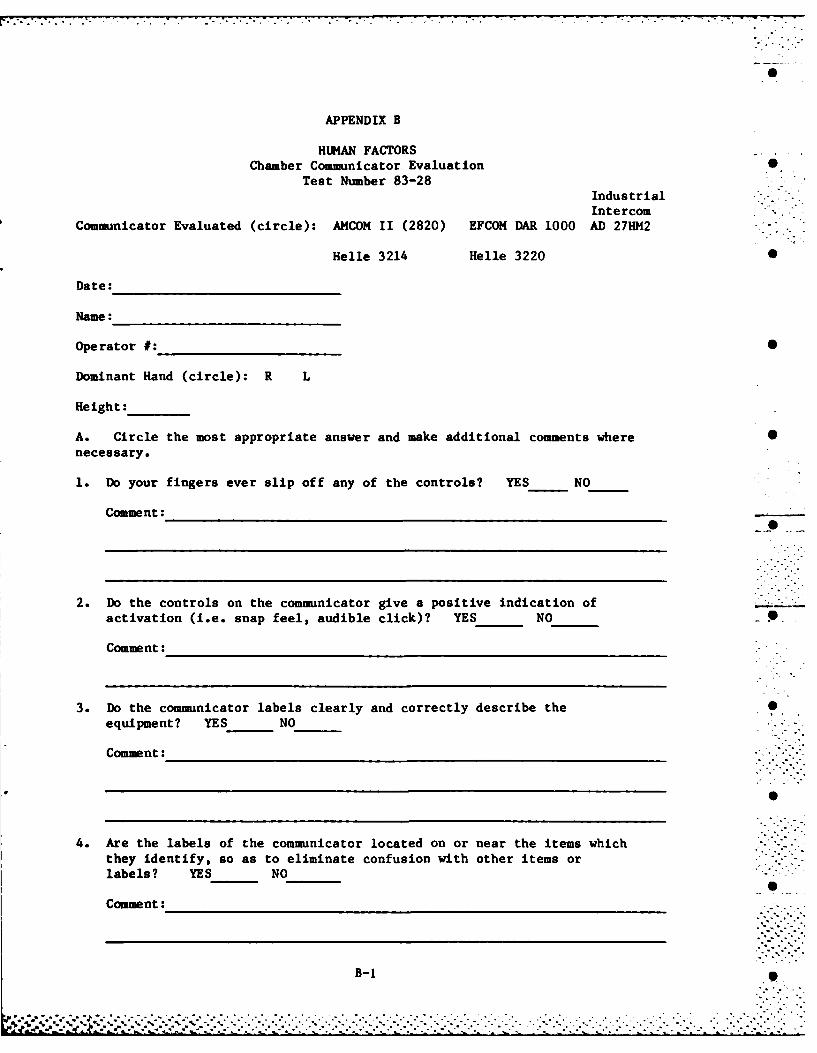
APPENDIX B
HUMAN FACTORSChamber Communicator Evaluation 0
Test Number 83-28IndustrialIntercom
Communicator Evaluated (circle): AMCOM II (2820) EFCOM DAR 1000 AD 27HM2 -""
Helle 3214 Helle 3220 •
Date:
Name:
Operator #: 0
Dominant Hand (circle): R L
Height:
A. Circle the most appropriate answer and make additional comments where Snecessary.
1. Do your fingers ever slip off any of the controls? YES NO
Comment:
2. Do the controls on the communicator give a positive indication ofactivation (i.e. snap feel, audible click)? YES NO_____
Comment:
3. Do the communicator labels clearly and correctly describe the Sequipment? YES_ NO______
Comment:
4. Are the labels of the communicator located on or near the items whichthey identify, so as to eliminate confusion with other items orlabels? YES NO_______
Comment:
B-1

83-28 (Continued)
5. Did you ever reach for, or operate, the wrong switch or knob? YES NO
Comment:
I p q
B. Answer the following questions by inserting the number corresponding tothe appropriate rating next to the question.
Key: 1 2 3 4 5
poor below satisfactory above excellent 0
average average
6. Rate the ease of operation of controls on the communicator:
Comment: S
7. Rate the location of controls on the communicator:
Comment:
8. Rate the clarity of sound received through the communicator from insidethe chamber:________
Comment:
9. Rate the construction (i.e. materials, craftsmanship) of thecommunicator:____
Comment:
10. Rate the aesthetics (beauty) of the communicator:________
Comment:
B-2S
* . * . . . . - . . - .* . , *. ° . .-. ** ....- *. . . - *.• .. .*.. . . . . - . . . . .. . . ... . . - . .. . .. in ..- .

83-28 (Continued)
C. Comment on how you would improve this communicator:_ _________
Do you have confidence in the performance of this equipment? YES NO
*D. Remarks on any item of importance to you that was not covered by thisquestionnaire:__________________________ ______
B-3
1-8
J 4I
. . . . . . . . . .