terrestrial laser scanner towers - fig ... laser scanner for surveying and monitoring middle age...
TRANSCRIPT
FIG Congress 2010 Facing the Challenges – Building the Capacity Sydney, Australia, 11‐16 April 2010 1
TERRESTRIAL LASER SCANNER FOR SURVEYING AND
MONITORING MIDDLE AGE TOWERS
Eleonora BERTACCHINI, Emanuele BONI, Alessandro CAPRA, Cristina CASTAGNETTI, Marco DUBBINI, Italy
Laboratory of Geomatics Dept. of Mechanical and Civil Engineering University of Modena and Reggio Emilia
XXIV FIG International Congress 2010 - 11-16 April, Sidney, Australia Session TS 4D - TLS applications I -paper n.4445
TLS surveying for 3D model resitution and for geometrical determination of the structures
Surveying and data processing methods in order to:
• define the height of the towers with respect to the gorund or, if possible, with respect to a benchmark of known height;
• determine the overhang of the towers and the direction of greatest vertical deviation;
•analyze the planimetric ad altymetric trajectory of geometrical barycenter versus the height variation
• enhance the diagnostic approach of TLS 3D surveying
Introduction
Scan Station 2 model of Leica was used.
Size sampling of 8 mm was used from each scan station
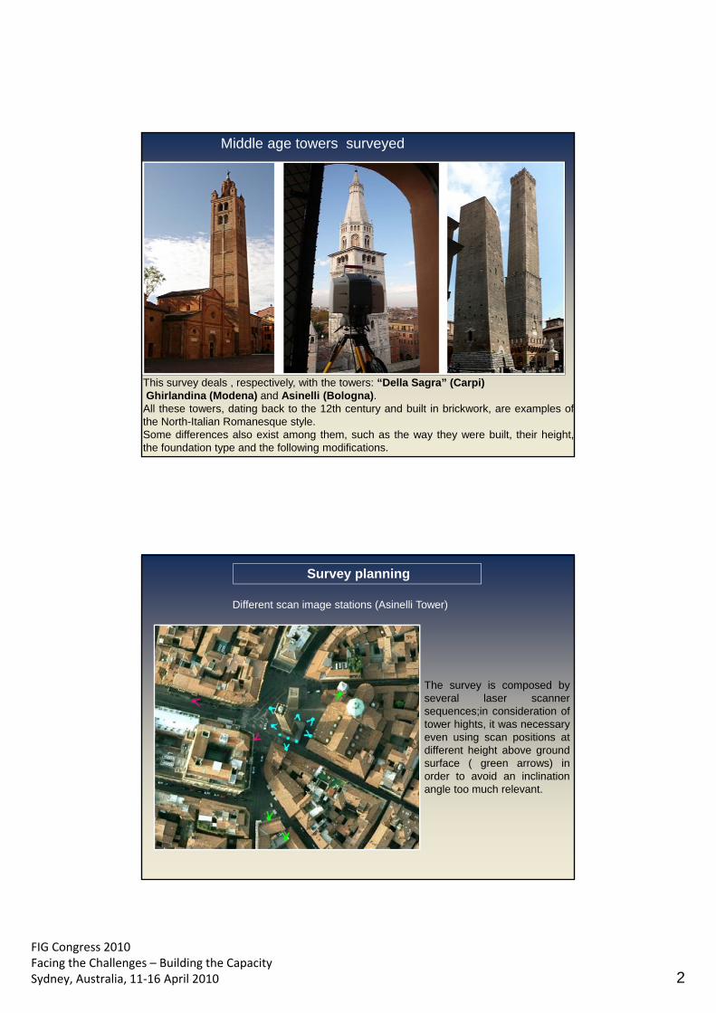
FIG Congress 2010 Facing the Challenges – Building the Capacity Sydney, Australia, 11‐16 April 2010 2
Middle age towers surveyed
This survey deals , respectively, with the towers: “Della Sagra” (Carpi) Ghirlandina (Modena) and Asinelli (Bologna). All these towers, dating back to the 12th century and built in brickwork, are examples of the North-Italian Romanesque style. Some differences also exist among them, such as the way they were built, their height, the foundation type and the following modifications.
Different scan image stations (Asinelli Tower)
The survey is composed by several laser scanner sequences;in consideration of tower hights, it was necessary even using scan positions at different height above ground surface ( green arrows) in order to avoid an inclination angle too much relevant.
Survey planning
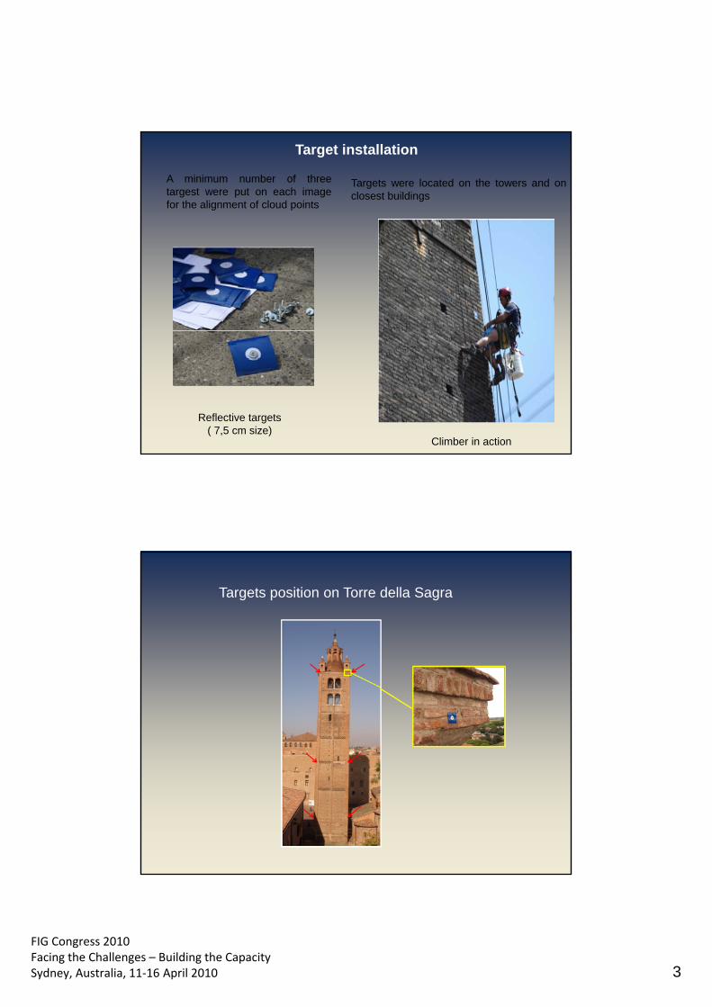
FIG Congress 2010 Facing the Challenges – Building the Capacity Sydney, Australia, 11‐16 April 2010 3
Reflective targets ( 7,5 cm size)
Climber in action
A minimum number of three targest were put on each image for the alignment of cloud points
Targets were located on the towers and on closest buildings
Target installation
Targets position on Torre della Sagra
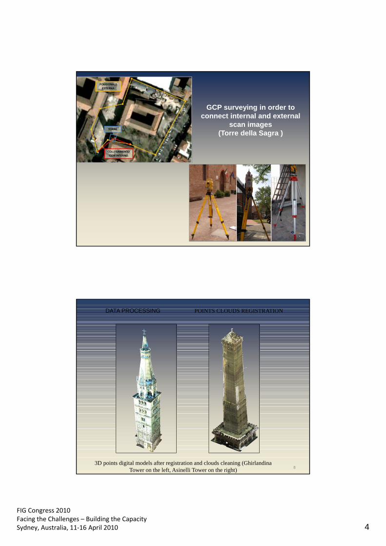
FIG Congress 2010 Facing the Challenges – Building the Capacity Sydney, Australia, 11‐16 April 2010 4
GCP surveying in order to connect internal and external
scan images (Torre della Sagra )
8
DATA PROCESSING POINTS CLOUDS REGISTRATION
3D points digital models after registration and clouds cleaning (Ghirlandina Tower on the left, Asinelli Tower on the right)
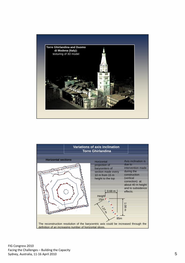
FIG Congress 2010 Facing the Challenges – Building the Capacity Sydney, Australia, 11‐16 April 2010 5
Torre Ghirlandina and Duomo di Modena (Italy):
texturing of 3D model
Height 15m
1.08 m
85m
0.68 m
Horizontal projection of barycenters of section made every 10 m from 15 m height to the top
Horizontal sections
Variations of axis inclination Torre Ghirlandina
The reconstruction resolution of the barycentric axis could be increased through the definition of an increasing number of horizontal slices.
Axis inclination is due to intervention made during the construction (vertical correction) at about 40 m height and to subsidence effects.
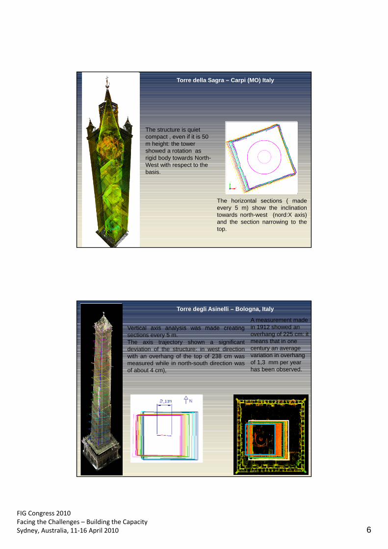
FIG Congress 2010 Facing the Challenges – Building the Capacity Sydney, Australia, 11‐16 April 2010 6
The horizontal sections ( made every 5 m) show the inclination towards north-west (nord:X axis) and the section narrowing to the top.
The structure is quiet compact , even if it is 50 m height: the tower showed a rotation as rigid body towards North-West with respect to the basis.
Torre della Sagra – Carpi (MO) Italy
m
Vertical axis analysis was made creating sections every 5 m. The axis trajectory shown a significant deviation of the structure: in west direction with an overhang of the top of 238 cm was measured while in north-south direction was of about 4 cm),
Torre degli Asinelli – Bologna, Italy
A measurement made in 1912 showed an overhang of 225 cm: it means that in one century an average variation in overhang of 1,3 mm per year has been observed.
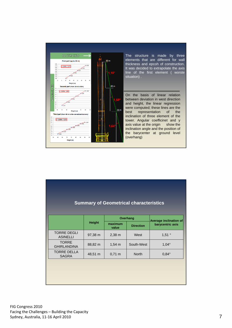
FIG Congress 2010 Facing the Challenges – Building the Capacity Sydney, Australia, 11‐16 April 2010 7
The structure is made by three elements that are different for wall thickness and epcoh of construction. It was decided to extrapolate the axis line of the first element ( worste situation) .
On the basis of linear relation between deviation in west direction and height, the linear regression were computed; these lines are the best representation of the inclination of three element of the tower. Angular coefficinet and y axis value at the origin show the inclination angle and the position of the barycenter at ground level (overhang)
Height Overhang
Average inclination of barycentric axis maximum
value Direction
TORRE DEGLI ASINELLI
97,38 m 2,38 m West 1,51 °
TORRE GHIRLANDINA
88,82 m 1,54 m South-West 1,04°
TORRE DELLA SAGRA
48,51 m 0,71 m North 0,84°
Summary of Geometrical characteristics
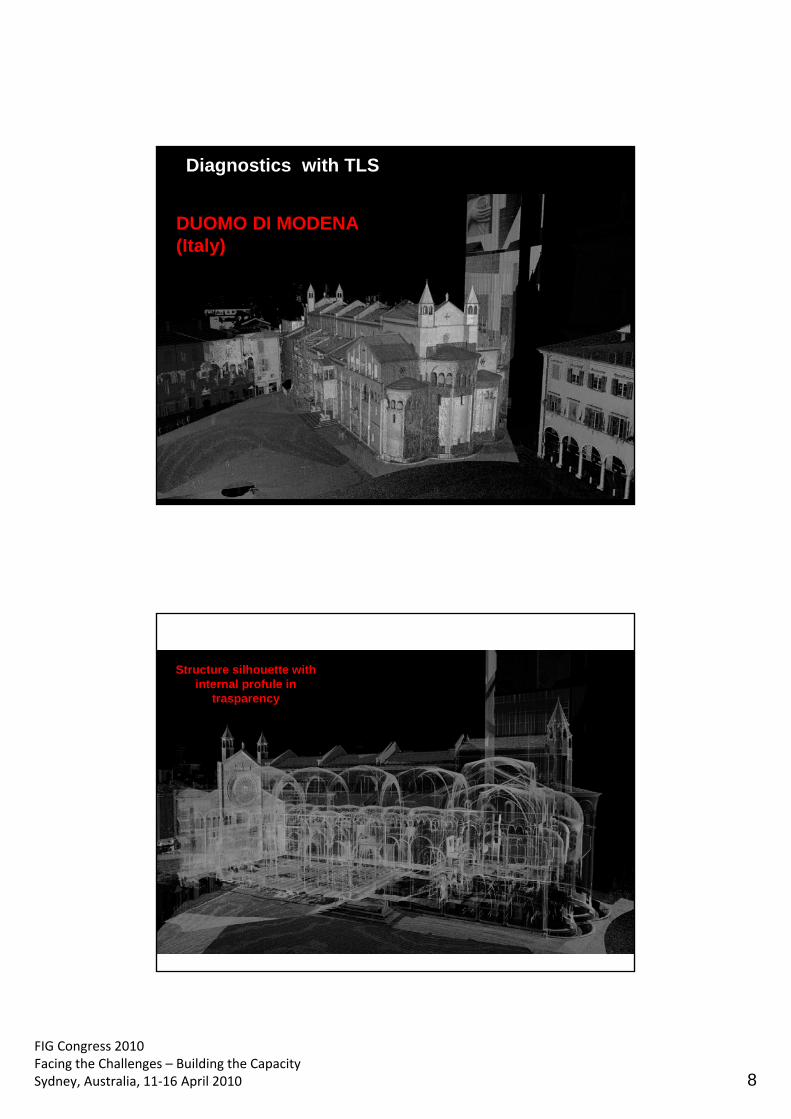
FIG Congress 2010 Facing the Challenges – Building the Capacity Sydney, Australia, 11‐16 April 2010 8
DUOMO DI MODENA (Italy)
Diagnostics with TLS
Structure silhouette with internal profule in
trasparency
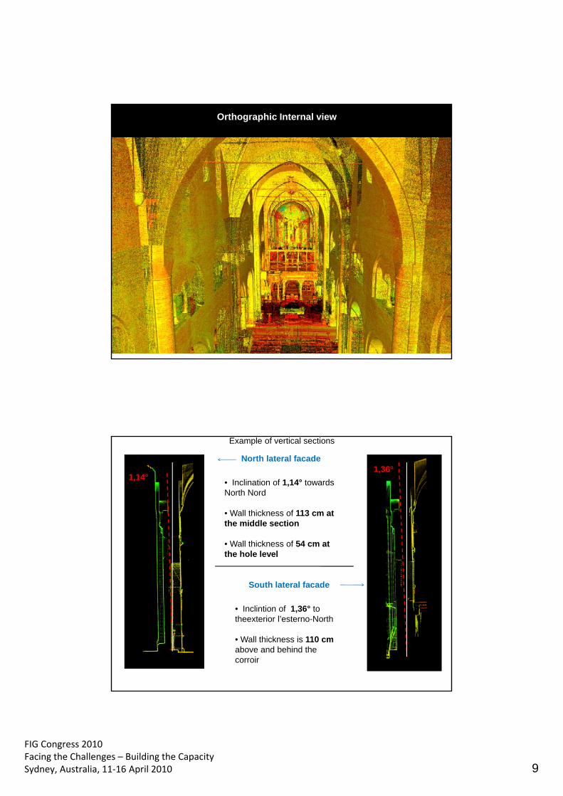
FIG Congress 2010 Facing the Challenges – Building the Capacity Sydney, Australia, 11‐16 April 2010 9
Orthographic Internal view
North lateral facade
• Inclination of 1,14° towards North Nord
• Wall thickness of 113 cm at the middle section • Wall thickness of 54 cm at the hole level
1,14°
South lateral facade
• Inclintion of 1,36° to theexterior l’esterno-North
• Wall thickness is 110 cm above and behind the corroir
1,36°
Example of vertical sections
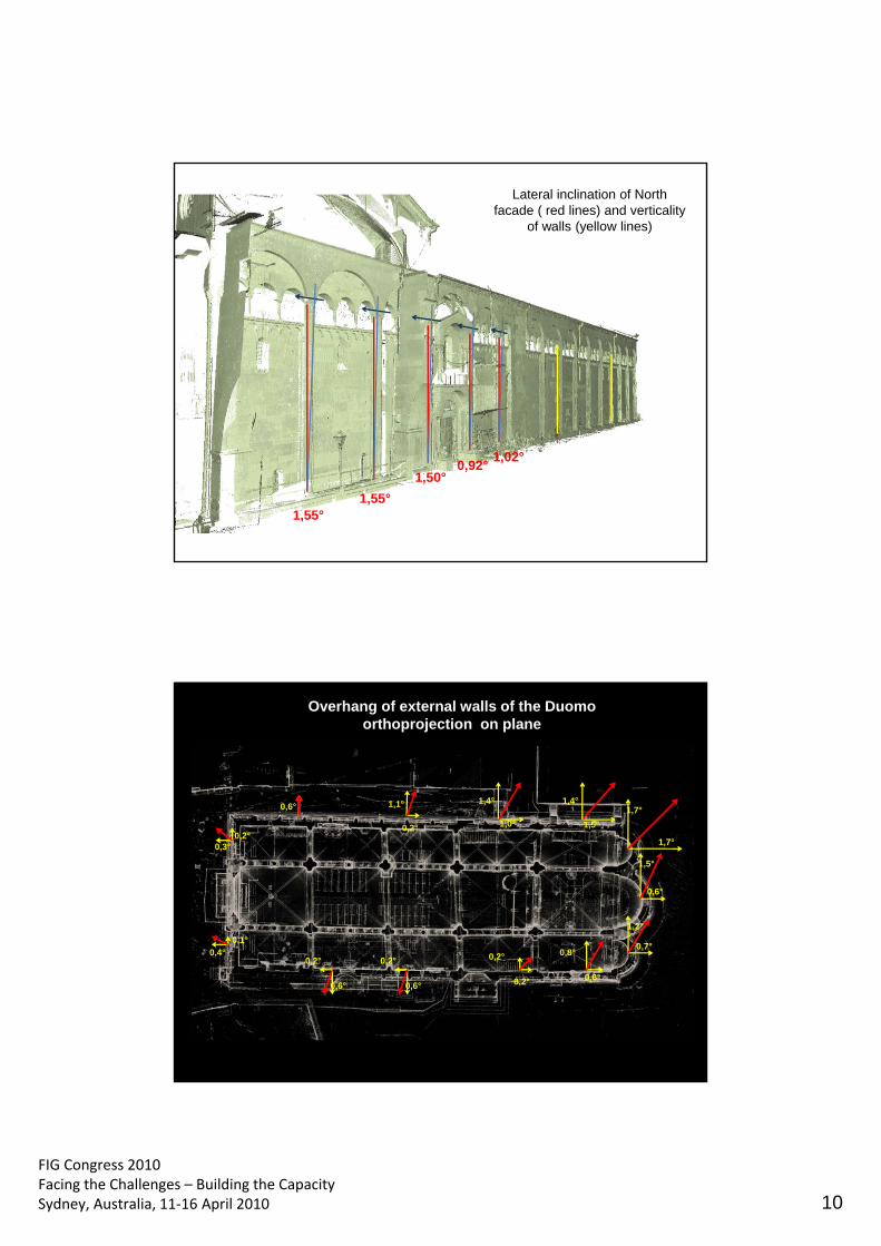
FIG Congress 2010 Facing the Challenges – Building the Capacity Sydney, Australia, 11‐16 April 2010 10
Lateral inclination of North facade ( red lines) and verticality
of walls (yellow lines)
1,55° 1,55°
0,92° 1,50°
1,02°
0,6° 1,1°
1,5°
0,7°
0,6°
1,7°
0,2°
0,8°
0,6°
0,3°
0,4°
Overhang of external walls of the Duomo orthoprojection on plane
0,2° 0,2°
0,1°
0,2° 1,0° 0,2°
1,5°
1,2°
0,6°
1,4°
1,7°
0,6°
0,2°
1,4°
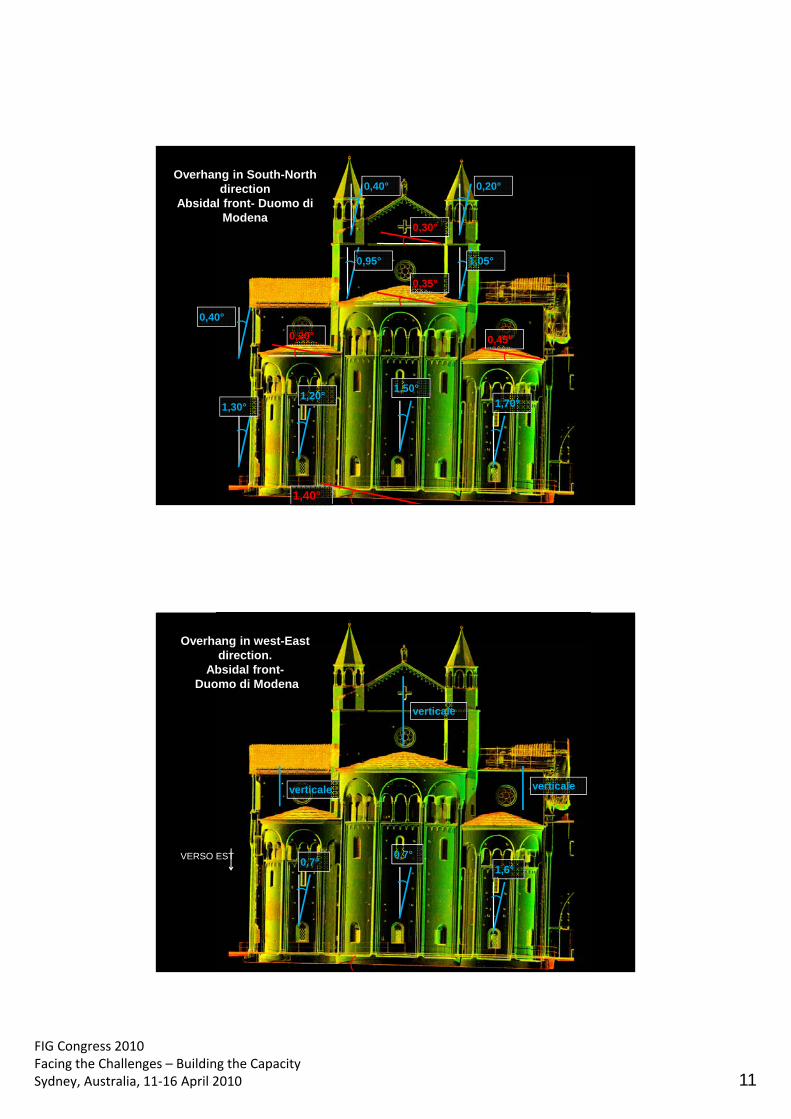
FIG Congress 2010 Facing the Challenges – Building the Capacity Sydney, Australia, 11‐16 April 2010 11
1,40°
0,35°
0,20°
0,30°
0,45°
0,20° 0,40°
0,95° 1,05°
1,20° 1,50°
1,70°
0,40°
1,30°
Overhang in South-North direction
Absidal front- Duomo di Modena
verticale
verticale
0,7° 0,7°
1,6°
Overhang in west-East direction.
Absidal front- Duomo di Modena
verticale
VERSO EST
FIG Congress 2010 Facing the Challenges – Building the Capacity Sydney, Australia, 11‐16 April 2010 12
TLS surveying for 3D restitution and geometrical determination of the structure with good accuracy at a centimeter level
The surveying procedure and processing methods allow an accurate determination of towers height and inclination. The achieved accuracy (centimetric-level precision) is a great result in relation to the short survey and processing time which was required.
The exact and clear location of the geometrical barycenter, related to the horizontal slice at the base of the towers, could be sometimes very difficult; the actual overhang can only be known by means of the barycentric axis extrapolation to the ground level.
The application shows the diagnostic use of TLS 3D surveying; very important tool for conservation and restauration intervention
Laboratory of Geomatics Dept. of Mechanical and Civil Engineering University of Modena and Reggio Emilia
XXIV FIG International Congress 2010 - 11-16 April, Sidney, Australia Session TS 4D - TLS applications I -paper n.4445
Conclusion