terrasar x
DESCRIPTION
radar imaging satellite skdfjaskdfj askdjfa skdjfka dkfja dkfja ksdjf kadfkasj dkfjaskd jfkasd fkjdfk asdjkfTRANSCRIPT

Airbus Defence and Space Geo-Intelligence Programme Line
TerraSAR-X Image Product Guide Basic and Enhanced Radar Satellite Imagery
TerraSAR-X Image Product Guide Basic and Enhanced Radar Satellite Imagery
Page 2 of 24 Issue 2.0 August 2014 Airbus Defence and Space
1 Introduction
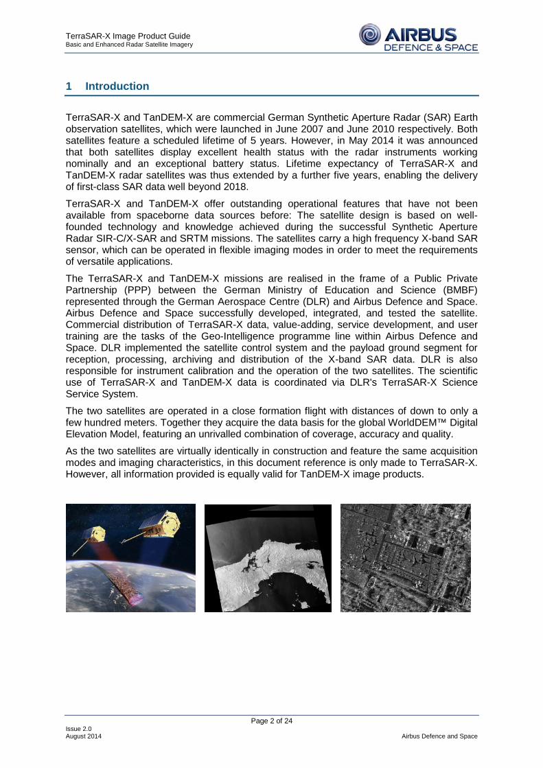
TerraSAR-X and TanDEM-X are commercial German Synthetic Aperture Radar (SAR) Earth observation satellites, which were launched in June 2007 and June 2010 respectively. Both satellites feature a scheduled lifetime of 5 years. However, in May 2014 it was announced that both satellites display excellent health status with the radar instruments working nominally and an exceptional battery status. Lifetime expectancy of TerraSAR-X and TanDEM-X radar satellites was thus extended by a further five years, enabling the delivery of first-class SAR data well beyond 2018.
TerraSAR-X and TanDEM-X offer outstanding operational features that have not been available from spaceborne data sources before: The satellite design is based on well-founded technology and knowledge achieved during the successful Synthetic Aperture Radar SIR-C/X-SAR and SRTM missions. The satellites carry a high frequency X-band SAR sensor, which can be operated in flexible imaging modes in order to meet the requirements of versatile applications.
The TerraSAR-X and TanDEM-X missions are realised in the frame of a Public Private Partnership (PPP) between the German Ministry of Education and Science (BMBF) represented through the German Aerospace Centre (DLR) and Airbus Defence and Space. Airbus Defence and Space successfully developed, integrated, and tested the satellite. Commercial distribution of TerraSAR-X data, value-adding, service development, and user training are the tasks of the Geo-Intelligence programme line within Airbus Defence and Space. DLR implemented the satellite control system and the payload ground segment for reception, processing, archiving and distribution of the X-band SAR data. DLR is also responsible for instrument calibration and the operation of the two satellites. The scientific use of TerraSAR-X and TanDEM-X data is coordinated via DLR's TerraSAR-X Science Service System.
The two satellites are operated in a close formation flight with distances of down to only a few hundred meters. Together they acquire the data basis for the global WorldDEM™ Digital Elevation Model, featuring an unrivalled combination of coverage, accuracy and quality.
As the two satellites are virtually identically in construction and feature the same acquisition modes and imaging characteristics, in this document reference is only made to TerraSAR-X. However, all information provided is equally valid for TanDEM-X image products.
TerraSAR-X Image Product Guide Basic and Enhanced Radar Satellite Imagery
Page 3 of 24 Issue 2.0 August 2014 Airbus Defence and Space
2 TerraSAR-X Facts
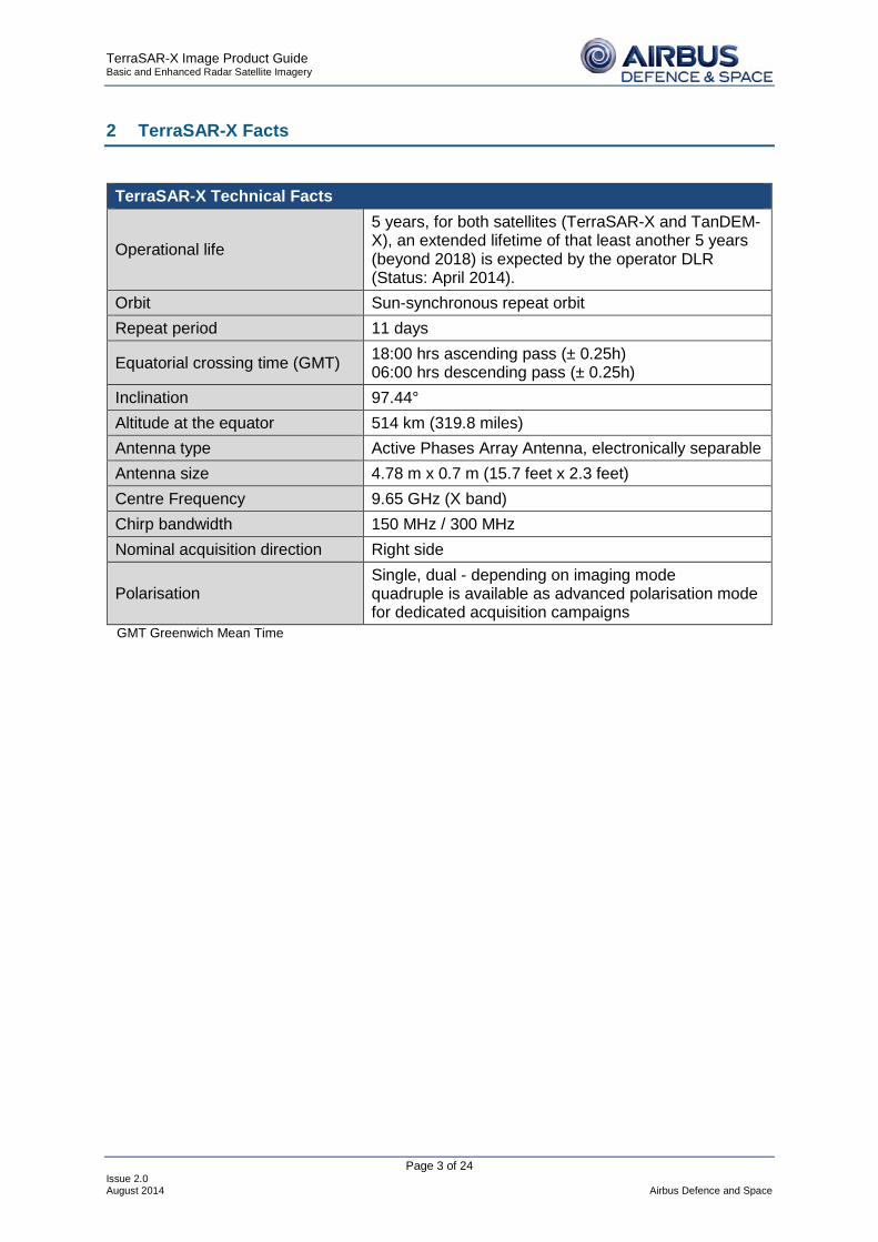
TerraSAR-X Technical Facts
Operational life
5 years, for both satellites (TerraSAR-X and TanDEM-X), an extended lifetime of that least another 5 years (beyond 2018) is expected by the operator DLR (Status: April 2014).
Orbit Sun-synchronous repeat orbit Repeat period 11 days
Equatorial crossing time (GMT) 18:00 hrs ascending pass (± 0.25h) 06:00 hrs descending pass (± 0.25h)
Inclination 97.44° Altitude at the equator 514 km (319.8 miles) Antenna type Active Phases Array Antenna, electronically separable Antenna size 4.78 m x 0.7 m (15.7 feet x 2.3 feet) Centre Frequency 9.65 GHz (X band) Chirp bandwidth 150 MHz / 300 MHz Nominal acquisition direction Right side
Polarisation Single, dual - depending on imaging mode quadruple is available as advanced polarisation mode for dedicated acquisition campaigns
GMT Greenwich Mean Time

TerraSAR-X Image Product Guide Basic and Enhanced Radar Satellite Imagery
Page 4 of 24 Issue 2.0 August 2014 Airbus Defence and Space
3 TerraSAR-X Imaging Modes
The standard TerraSAR-X operational mode is the single receive antenna mode from which the following imaging modes can be retrieved: SpotLight, StripMap, and ScanSAR. The single receive antenna mode uses a chirp bandwidth of up to 300 MHz.
The SpotLight imaging modes use phased array beam steering in azimuth direction to increase the illumination time, i.e. the size of the synthetic aperture. This leads to a restriction in the image / scene size. Thus, the scene size is technically restricted to a defined size: 10 km x 10 km (width x length) for the SpotLight (SL) mode and 5 to 10 km x 5 km (width x length) in the High Resolution SpotLight (HS) mode. The Staring SpotLight (ST) mode is an extreme case, in which the antenna footprint rests on the scene and the scene length corresponds to the length of the antenna footprint. Thus, the scene size is highly dependent on the incidence angle: at small incidence angle wide footprints at short length are received and with increasing incidence angle nearly equal proportions are obtained, i.e. 7.5 km x 2.5 km @ 20° incidence angle and 4 km x 3.7 km @ 60° incidence angle (width x length). This sophisticated imaging mode makes it possible to acquire data with up to 0.25 m resolution in Staring SpotLight mode, 1 m resolution in High Resolution SpotLight mode (acquired with a bandwidth of 300 MHz) and 2 m in SpotLight mode.
StripMap (SM) is the basic SAR imaging mode as known e.g. from ERS-1 and other radar satellites. The ground swath is illuminated with continuous sequence of pulses while the antenna beam is fixed in elevation and azimuth. This results in an image strip with a continuous image quality (in flight direction). StripMap dual polarisation data have a slightly lower spatial resolution and smaller swath than the single polarisation data.
In StripMap mode, a spatial resolution of up to 3 m can be achieved. The standard scene size is 30 km x 50 m (width x length) in order to obtain manageable image files; however, acquisition length is extendable up to 1,650 km.
In the ScanSAR imaging modes, electronic antenna elevation steering is used to acquire adjacent, slightly overlapping coverages with different incidence angles that are processed into one scene. In ScanSAR (SC) mode, a swath width of 100 km (and even more) is achieved by scanning four adjacent ground sub-swaths with quasi-simultaneous beams, each with different incidence angle.

TerraSAR-X Image Product Guide Basic and Enhanced Radar Satellite Imagery
Page 5 of 24 Issue 2.0 August 2014 Airbus Defence and Space
In Wide ScanSAR (WS) mode, a swath width of up to 270 km is achieved by scanning six adjacent ground sub-swaths. Due to the switching between the beams, only bursts of SAR echoes are received, resulting in a reduced bandwidth and hence, reduced azimuth resolution.
In ScanSAR mode a spatial resolution of up to 18.5 m is achieved, while for Wide ScanSAR a spatial resolution of 40 m is achieved. The standard scene size is 100 km x 150 km (width x length) for ScanSAR and up to 270 km x 200 km for Wide ScanSAR for easily manageable image file size. The acquisition length is extendable up to 1,650 km for ScanSAR and up to 1,500 km for Wide ScanSAR.
The advanced TerraSAR-X imaging modes use a dual receive antenna by splitting the antenna into two parts. The dual receive antenna is only available for ordering in case of designated mission campaigns, which are announced by the operator DLR. It enables the acquisition of the following products:
StripMap twin polarisation data in HH and VV at a standard scene size of 30 km x 50 km (width x length).
StripMap quadruple polarisation data recording the full scattering matrix, allows the derivation of further polarisation states (circular or elliptic).
The table below gives an overview of the operational modes of TerraSAR-X. The six different imaging modes are distinguished by their spatial resolution and coverage:

TerraSAR-X Image Product Guide Basic and Enhanced Radar Satellite Imagery
Page 6 of 24 Issue 2.0 August 2014 Airbus Defence and Space
Imaging Mode
Standard Scene Sizea [km]
Maximum Acquisition
Length [km]
Slant Range
Resolutionb [m]
Azimuth Resolutionb
[m]c Polarisation
Full Per-formance
Range [°]
Staring SpotLight
(ST) 4 x 3.7d 3.7 0.6 0.24 Single
(VV or HH) 20° to 45°
HighRes SpotLight 300 MHz (HS300)
10 x 5c 5 0.6 1.1 Single (VV or HH) 20° to 55°
HighRes SpotLight
(HS) 10 x 5 5
1.2
1.2
1.1
2.2
Single (VV or HH)
Dual (HH & VV)
20° to 55°
SpotLight (SL)
10 x 10 10
1.2
1.2
1.7
3.4
Single (VV or HH)
Dual (HH & VV)
20° to 55°
StripMap (SM)
30 x 50 single pol
15 x 50 dual pol
1,650
1.2
1.2
3.3
6.6
Single (VV or HH)
Dual
(HH & VV, HH & HV, or VV and
VH)
20° to 45°
ScanSAR (SC) 100 x 150 1,650 1.2 (at 150
MHz) 18.5 Single (VV or HH) 20° to 45°
Wide ScanSAR
(WS) 270 x 200c 1,500
Depending on range
bandwidth 1.7 - 3.3
40 Single
(VV, HH, HV or VH)
15.6° to 49°
a Width x length (range x azimuth) b Figures correspond to the Single Look Slant range Complex (SSC) image products c Figures correspond to the Single Look Slant range Complex (SSC) image products d Depending on incidence angle

TerraSAR-X Image Product Guide Basic and Enhanced Radar Satellite Imagery
Page 7 of 24 Issue 2.0 August 2014 Airbus Defence and Space
4 TerraSAR-X Product Suites
TerraSAR-X products are differentiated into two major product groups: Basic Image Products (or L1B Products) and Enhanced Image Products (EI Products).
Basic Image Products are satellite path oriented data sets. They correspond to the CEOS Level 1b quality and can be ordered as future acquisitions or from the data catalogue. In case of a future acquisition order, the customer can determine the following acquisition options:
Acquisition Options Area of Interest (or scene centre coordinate) Imaging Mode Staring SpotLight (ST)
High Resolution SpotLight 300MHz (HS300) High Resolution SpotLight (HS) SpotLight (SL) StripMap (SM) ScanSAR (SC) Wide ScanSAR (WS)
Polarisation Mode Single (S) for all modes Dual (D) for High Resolution SpotLight (HS), SpotLight (SL) and StripMap (SM)
Incidence Angle Range 15° - 60° e
Pass Direction Ascending (A) or Descending (D)
Acquisition Start and Stop Time
Polarisation Channels Single polarisation: HH or VV, for Wide ScanSAR additionally: HV or VH, Dual polarisation: HH/VV, for StripMap only: HH/HV or VV/VH
Naturally, for Basic Image Products ordered from the catalogue, these parameters are fixed.
Processing options for TerraSAR-X Basic Image Products, however, can be determined for both future acquisition orders and catalogue orders. The Basic Image Products processing options are described in the detailed in Section 5 of this document.
Enhanced Image Products are typically area of interest or map oriented products, which represent a higher level of processing in terms of a more precise geometric correction, orthorectification or mosaicking.
TerraSAR-X Basic Image Products are used as input for generating Enhanced Image Products. Thus they can be generated based on future acquisition, catalogue data, or a combination of both. For future acquisition orders, the customer can influence the acquisition options. More processing options and auxiliary raster data are part of the Enhanced Image Products; further described in section 6.
e Data outside performance range (see table chapter 3) might not fulfill the product specification.

TerraSAR-X Image Product Guide Basic and Enhanced Radar Satellite Imagery
Page 8 of 24 Issue 2.0 August 2014 Airbus Defence and Space
5 TerraSAR-X Basic Image Products
The SAR raw data are processed by the TerraSAR-X Multi Mode SAR Processor (TMSP). For each order - future acquisition order or catalogue order - the customer can specify processing options, which determine the Basic Image Product w.r.t.
■ the geometric and radiometric resolution,
■ the geometric projection and
■ the auxiliary information and annotation.
All TerraSAR-X Basic Image Products are processed and delivered in radar brightness β0, making them comparable to the detected ground range products from ERS-1 and 2, ENVISAT/ASAR and RADARSAT. In contrast to ENVISAT and ERS, the complex slant range products are also delivered in radar brightness.
With respect to the geometric projection and data representation of the data, TerraSAR-X Basic Image Products are differentiated into four product types, which are described in the following. Each product type is available individually; a combination is also possible.
5.1 Slant Range Product
The slant range product is a single look product of the focused radar signal. For this product, no additional processing options are available.
SSC - Single Look Slant Range Complex
The SSC product is a single look product of the focused radar signal. The pixels are spaced equidistant in azimuth (according to the pulse repetition interval PRI=1/PRF) and in slant range (according to the range sampling frequency). The data are represented as complex numbers containing amplitude and phase information. Each image pixel is processed to zero Doppler coordinates in range direction, i.e. perpendicular to the flight track. Due to the nature of azimuth/slant-
range coordinates, no geocoding is available. The SSC is delivered in the DLR-defined binary COSAR format (see TerraSAR-X Level1B Product Format Specification).
The product is compatible with the standard slant range products (SLC) available from ERS-1/2, ENVISAT ASAR, RADARSAT-1 and X-SAR/SIR-C.
The SSC product is intended for applications that require the full bandwidth and phase information, e.g. for SAR interferometry and polarimetry. Depending on the required application, this product may be preferred to geocoded data, since it does not include any radiometric artefacts, which may be introduced during spatial resampling and geocoding.

TerraSAR-X Image Product Guide Basic and Enhanced Radar Satellite Imagery
Page 9 of 24 Issue 2.0 August 2014 Airbus Defence and Space
5.2 Detected Products
In the detected products, the spatial resolution is reduced (the number of looks is increased accordingly) in order to reduce speckle and thermal noise, i.e. to improve the radiometric resolution. Three different product types of detected image products exist for all imaging modes.
MGD - Multi Look Ground Range Detected
The MGD product is a detected multi look product with reduced speckle and approximately square resolution cells. The image coordinates are oriented along flight direction and along ground range. The pixel spacing is equidistant in azimuth and in ground range. For the slant to ground range projection the WGS84 ellipsoid and an average, constant terrain height value are used.
The MGD corresponds to the ERS-1/2 PRI or ENVISAT ASAR product called ASA_IMP_1P.
The advantage of this product is the fact that no image rotation to a map coordinate system has been performed and interpolation artefacts are thus avoided. This product is useful, if geocoding or orthorectification is to be applied by the customer, or in case geocoding is not required.
GEC - Geocoded Ellipsoid Corrected
The GEC product is a multi-look detected product, which is resampled and projected to the WGS84 reference ellipsoid assuming one average height. The image is represented in map geometry with ellipsoidal corrections only, thus no terrain correction is performed. Available grid formats are UTM (Universal Transversal Mercator) and UPS (Universal Polar Stereographic).
Since the ellipsoid correction does not use height information from a Digital Elevation Model (DEM) for geometric correction, the pixel location accuracy varies depending on the local terrain. For other types of relief, the terrain induced SAR specific distortions are not corrected and significant location shifts can appear, particularly for a strong relief and/or steep incidence angles (see Annex for details on pixel location accuracy).
The product corresponds to the ERS-1/2 GEC or the ENVISAT SAR product called ASA_IMG_1P.
The GEC allows a fast orientation for the interpreter. Further, the data can be combined directly with other sources of information. For flat terrain, a good pixel location accuracy of the multi-temporal and reference data sets is achieved.

TerraSAR-X Image Product Guide Basic and Enhanced Radar Satellite Imagery
Page 10 of 24 Issue 2.0 August 2014 Airbus Defence and Space
EEC - Enhanced Ellipsoid Corrected
The EEC product is a multi-look detected product as well, projected and resampled to the WGS84 reference ellipsoid. However, image distortions caused by varying terrain height are corrected using an external Digital Elevation Model (DEM). The image is represented in map geometry with terrain correction. The available map projections are UTM or UPS.
The pixel localization of this product is of a higher accuracy, however, it depends on the type of terrain, the quality and the resolution of the DEM used for the orthorectification and the incidence angle of the acquisition (see Annex for details on pixel location accuracy).
The product corresponds to the ERS-1/2 GTC or respective ENVISAT ASAR DLR-value-added product.
The EEC product features the highest level of geometric correction available for TerraSAR-X Basic Image Products and is thus quickly interpretable and combinable with other sources of information.
5.3 Basic Image Products Processing Options
For the Detected Products, the customer can specify additional processing options. These influence the spatial / radiometric resolution and the auxiliary information and annotation.
5.3.1 Resolution Mode
In contrast to ERS-1 and ENVISAT/ASAR, the range resolution of TerraSAR-X is close to or even better than the azimuth resolution and looks cannot be derived by degrading the azimuth resolution. Therefore, two variants of detected products have been designed: one is optimised for resolution (spatially enhanced) and one is optimised for radiometry (radiometrically enhanced). In either variant, a square ground resolution cell is implemented.
For each Detected Product, the customer can choose either one of the two resolution modes: spatially enhanced (SE) or radiometrically enhanced (RE) products.
The Spatially Enhanced Product (SE) is designed for the highest possible square ground resolution. Depending on imaging mode, polarisation and incidence angle, the larger resolution value of azimuth or ground range determines the square pixel size. The smaller resolution value is adjusted to this size and the corresponding reduction of the bandwidth is used for speckle reduction.
For the two ScanSAR modes no Spatially Enhanced Products are available.
The Radiometrically Enhanced Product (RE) is optimised with respect to radiometry. The range and azimuth resolution are intentionally reduced. This significantly reduces speckle by averaging 5 to 7 looks to obtain a radiometric resolution of about 1.5 dB.

TerraSAR-X Image Product Guide Basic and Enhanced Radar Satellite Imagery
Page 11 of 24 Issue 2.0 August 2014 Airbus Defence and Space
5.3.2 Orbit Measurement Precisions Positional accuracies depend (among other things) on the precision of the orbit measurement (see Annex for details on pixel location accuracy).
Three orbit precisions are available for Basic Product generation. Customers can choose between them, taking their availability into account.
Type of Orbit Accuracy Processing Purpose
Predicted Orbit 700 m along track Used for processing of Near Real Time products; available within 2 to 4 h.
Rapid Orbit 2 m (3-d, 1 sigma) Standard processing for basic image products; available within 1 to 2 days after acquisition.
Science Orbit 20 cm (3-d, 1 sigma) aiming at 10 cm
The science orbit provides the highest location accuracy and is recommended for data stacks (e.g. time series, interferometry). Basic image products generated with this orbit are typically available within 5 to 7 days after acquisition.
5.3.3 Auxiliary Raster Products
A Geocoded Incidence Angle Mask (GIM) is available for the Enhanced Ellipsoid Corrected (EEC) product. The GIM contains information on the local incidence angle and on the location of radar shadowing and layover in a coded mask. The mask can be used for further processing such as radiometric calibration.
The EEC product is always accompanied by a DEM Coverage Map (DEM Map). The DEM Map is a matrix containing an index that identifies the name(s) of the DEM(s) used for the orthorectification (EEC generation) process. A lookup table, which describes the index, is part of the delivered product.
The DEM used for EEC product generation itself is typically not a TerraSAR-X product and is not delivered with the product.
5.3.4 File Format
The TerraSAR-X Basic Image Product SSC is delivered in the DLR-defined COSAR binary format. The detected products are delivered in GeoTiff format. The annotation information of all Basic Image Products is provided in xml format.
Standard COTS software packages (e.g. Leica Geosystems Erdas Imagine, PCI Geomatics, ENVI, etc.) support the formats. For up-to-date information on software that supports TerraSAR-X data, please visit http://www.geo-airbusds.com/en/3018-software-tools.

TerraSAR-X Image Product Guide Basic and Enhanced Radar Satellite Imagery
Page 12 of 24 Issue 2.0 August 2014 Airbus Defence and Space
5.3.5 Processor Gain Attenuation
TerraSAR-X Basic Image Products are available in 16 bit integer values. As sometimes the backscatter values of the TerraSAR-X images exceed this data range, a scaling of the values is required. It might happen that the backscatter values of very bright targets (e.g. corner reflectors) are clipped due to this scaling.
The processing parameter processor gain attenuation parameter influences the scaling, i.e. the clipping of values of very bright targets is prevented at the cost of not optimally quantised radiometry for low backscatter areas. Thus, it can be used to increase or reduce the radiometric contrast between very high returns (from land) versus very low return (water).
Selectable values: 0 dB (default), 10 dB and 20 dB
Examples:
For military applications, where shadows or low values are of interest, the default value 0 dB is usually used. For images of very dense urban area acquired in the Staring Spotlight mode, which are characterised by a lot of very high returns, the recommended value for the processor gain attenuation is 10 dB.

TerraSAR-X Image Product Guide Basic and Enhanced Radar Satellite Imagery
Page 13 of 24 Issue 2.0 August 2014 Airbus Defence and Space
6 TerraSAR-X Enhanced Image Products
TerraSAR-X Enhanced Image (EI) Products are mainly focussed on a particular area of interest or are map products, which represent a higher level of processing in terms of radiometric correction and orthorectification, mosaics, subsets and merges.
The Enhanced Image Products are based on TerraSAR-X Basic Image Products and they can be generated from future acquisition, catalogue orders or a combination of both. Thanks to their higher processing level, the products provide more processing options than the Basic Image Products, along with additional auxiliary information. With these products, customers are not limited to satellite specific images and image strips but can order a full geometrically and radiometrically adjusted coverage of a particular region of interest. Further, it is possible to generate Enhanced Image Products from other Enhanced Image Products, e.g. a radar mosaic based on high-quality orthorectified images.
In the next chapter the different TerraSAR-X Enhanced Image Products are described, followed by details regarding the main processing options.
6.1 Enhanced Image Products
ORISAR - Orthorectified Image
The Orthorectified Image product is a highly accurate geocoded image with terrain correction included. Terrain distortions inherent in satellite imagery, particularly in areas of high relief, are removed. Due to the major influence of the Digital Elevation Model (DEM) on the pixel location accuracy of an orthorectified image, only high precision DEMs are used for ORISAR production. The result shows increased pixel location accuracy in comparison to an EEC product. (See Annex for more information on the influencing factors on pixel location accuracy and the quality of DEMs used for EEC production.)
The high precision DEMs used for ORISAR production can either be provided by the customer or be purchased by Airbus Defence and Space. The image is represented in map geometry. The standard map projections are UTM or UPS with WGS84 ellipsoid.
ORISAR products are available with the same radiometric representation in radar brightness β0 as the Basic Image Products, but an additional radiometric calibration (σ0) or radiometric normalisation (γ0) can be ordered (see RaNSAR).
This product has a higher level of geometric correction in comparison to Basic Image Products. It is quickly interpretable and an excellent complement to other sources of information.

TerraSAR-X Image Product Guide Basic and Enhanced Radar Satellite Imagery
Page 14 of 24 Issue 2.0 August 2014 Airbus Defence and Space
RaNSAR - Radiometrically Corrected Image
The Basic Image Products GEC and EEC are delivered in radar brightness (β0). The customer can request an additional radiometric calibration or radiometric normalisation of these products. The resulting product is called RaNSAR (radiometrically corrected or normalised GEC or EEC image).
Both corrections compensate for topography induced effects such as local pixel scattering area and local incidence angle. Radiometric
calibration and normalisation lead to an absolute measurement of the sigma naught (σ0) or gamma naught (γ0) coefficient respectively, depending on the customer’s selection (see also chapter 6.2.1). Like the Basic Image Products GEC and EEC the RaNSAR product is represented in map geometry. The standard map projections are UTM or UPS with WGS84 ellipsoid.
Radiometric correction is recommended if the imagery is to be used for classifications which do not take angular dependencies of the SAR data into account. Further, it is also important whenever several images of the same area or neighbouring areas are to be composed, as this minimises the differences in the radiometry of the various images.
MCSAR - Mosaic
In order to cover a geographical area larger than a standard scene, neighbouring geocoded or orthorectified images are combined into one image in a seamless way. Supported input products are ORISAR, EEC or GEC depending on the customer’s localisation accuracy requirements.
During production, specific mosaicking boundaries are automatically detected, e.g. along natural edges or line structures like tree lines, streets or field borders. These are used in the mosaicking production in
order to avoid the visibility of cutting edges in the final image product. All scenes are radiometrically balanced, which results in a seamless mosaic without breaks or visible cutlines. The MCSAR is represented in map geometry. The standard map projections are UTM or UPS with WGS84 ellipsoid.
The product provides seamless image information of an area larger than a standard scene. It is quickly interpretable and combinable with other sources of information and can be used for map sheet generation.
ADMSAR - Ascending / Descending Merge
The ADMSAR product is an orbit merge, i.e. a combination of SAR images from ascending and descending right looking orbits is used for image analysis. This achieves a reduction of the impact of the typical SAR effects of shadow and layover, which are usually visible and may obscure parts of the area under investigation.
EEC, ORISAR or MCSAR from both orbit directions are used as an input to ADMSAR generation. The Source Image Mask (SOU) shows the origin of
each pixel in the product. Optionally, the delivery includes all individual orthorectified source images (ORISAR) for the respective ascending and descending orbits.

TerraSAR-X Image Product Guide Basic and Enhanced Radar Satellite Imagery
Page 15 of 24 Issue 2.0 August 2014 Airbus Defence and Space
The ADMSAR is represented in map geometry. The standard map projections are UTM or UPS with WGS84 ellipsoid. The ADMSAR is of particular interest for areas with steep mountainous terrain, where shadow and layover can significantly disturb the analysis.
6.2 Enhanced Image Products Processing Options
In addition to the processing options for the TerraSAR-X Basic Imagery, a number of processing options are available for Enhanced Image Products only:
6.2.1 Radiometric Correction
TerraSAR-X Basic Image Products are delivered in radar brightness (β0). A radiometric correction yielding either sigma naught or gamma naught is delivered for the Enhanced Image Products RANSAR or optionally also for ORISAR (see chapter 6.1).
The following types of radiometric corrections are selectable for ORISAR and RANSAR:
Radiometric Calibration
The correction factor sinθ results in sigma naught (σ°). It is normalised over the actual ground area and thus it is independent of the acquisition geometry and topography. Radiometric calibration is preferred by scientists as sigma naught values are those values directly related to the ground.
Radiometric Normalisation
The correction function 1/cosθ is applied to sigma naught, which results in gamma naught (γ°). It is normalised orthogonally to the incidence ray. A relatively constant reflectivity is maintained for a wide range of incidence angles, particularly for rough surfaces, thus it is preferred for calibration purposes.
6.2.2 Auxiliary Raster Products
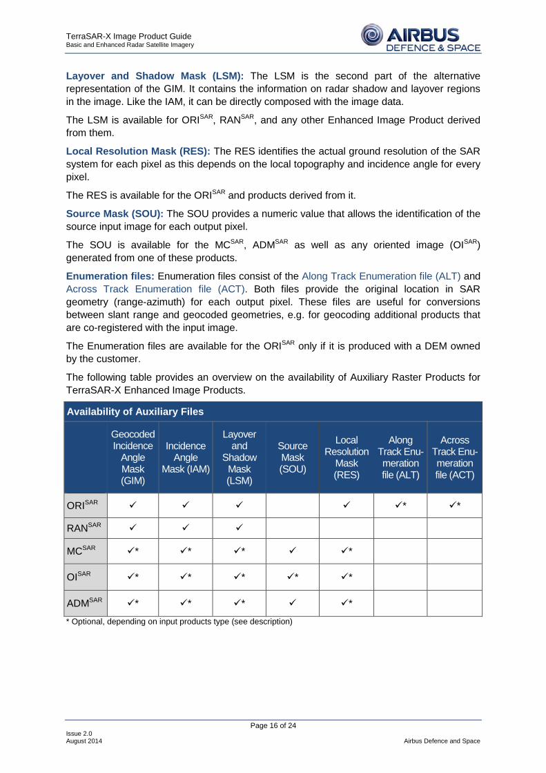
All TerraSAR-X Enhanced Image Products are accompanied by auxiliary raster products, which contain conversion, positional information and / or other ancillary information. Depending on the Enhanced Image Product type, different auxiliary raster products are available. All auxiliary raster products available for the different Enhanced Image Products are detailed below:
Geocoded Incidence Angle Mask (GIM): The GIM contains information on the local incidence angle and on the location of radar shadow and layover. The mask can be used for further processing like radiometric calibration using the incidence angle information.
The GIM is available for EEC products and for ORISAR, RANSAR, and any other Enhanced Image Product derived from them.
Incidence Angle Mask (IAM): The IAM is an alternative representation of the local incidence angle information. The values are not coded, thus the mask can be applied directly for further processing such as radiometric calibration.
The IAM is available for ORISAR, RANSAR, and any other Enhanced Image Product derived from them.
TerraSAR-X Image Product Guide Basic and Enhanced Radar Satellite Imagery
Page 16 of 24 Issue 2.0 August 2014 Airbus Defence and Space
Layover and Shadow Mask (LSM): The LSM is the second part of the alternative representation of the GIM. It contains the information on radar shadow and layover regions in the image. Like the IAM, it can be directly composed with the image data.
The LSM is available for ORISAR, RANSAR, and any other Enhanced Image Product derived from them.
Local Resolution Mask (RES): The RES identifies the actual ground resolution of the SAR system for each pixel as this depends on the local topography and incidence angle for every pixel.
The RES is available for the ORISAR and products derived from it.
Source Mask (SOU): The SOU provides a numeric value that allows the identification of the source input image for each output pixel.
The SOU is available for the MCSAR, ADMSAR as well as any oriented image (OISAR) generated from one of these products.
Enumeration files: Enumeration files consist of the Along Track Enumeration file (ALT) and Across Track Enumeration file (ACT). Both files provide the original location in SAR geometry (range-azimuth) for each output pixel. These files are useful for conversions between slant range and geocoded geometries, e.g. for geocoding additional products that are co-registered with the input image.
The Enumeration files are available for the ORISAR only if it is produced with a DEM owned by the customer.
The following table provides an overview on the availability of Auxiliary Raster Products for TerraSAR-X Enhanced Image Products.
Availability of Auxiliary Files
Geocoded Incidence
Angle Mask (GIM)
Incidence Angle
Mask (IAM)
Layover and
Shadow Mask (LSM)
Source Mask (SOU)
Local Resolution
Mask (RES)
Along Track Enu-meration file (ALT)
Across Track Enu-meration file (ACT)
ORISAR * *
RANSAR
MCSAR * * * *
OISAR * * * * *
ADMSAR * * * *
* Optional, depending on input products type (see description)

TerraSAR-X Image Product Guide Basic and Enhanced Radar Satellite Imagery
Page 17 of 24 Issue 2.0 August 2014 Airbus Defence and Space
6.3 Customisation Services
Customisation Services are available for TerraSAR-X Basic and Enhanced Image Products. In the following the different customisation services are detailed.
6.3.1 Oriented Image (OISAR) OISAR - Oriented Image
The Oriented Image is a subset of an orthorectified or geocoded image scene, a mosaic or an ascending / descending merge. The subset region is defined by the customer via an Area of Interest polygon or corner coordinates of the desired region. The product can either be characterised by the user defined Area of Interest or by a map sheet orientation according to relevant mapping standards or customer defined extensions.
The product is represented in map geometry, with the standard map projections being UTM or UPS with WGS84 ellipsoid.
The OISAR can be combined with other sources of information, thus it can be used as direct input e.g. for map sheet generation. Customers receive an image that covers the selected Area of Interest instead of satellite-typical image strips that cover the area only in fractions.
6.3.2 Projections
The standard cartographic projections for TerraSAR-X Basic and Enhanced Image Products are Universal Transversal Mercator (UTM) and Uniform Polar Stereographic (UPS) with WGS84 ellipsoid.
The Customisation Services include the transfer of the products to other cartographic projections selectable by the customer.
6.3.3 Scaling
All TerraSAR-X Basic and Enhanced Image Products are produced in 16 bit. On occasion, the data may be reduced to 8 bit, e.g. for visualisation purposes in mapping applications, or in case that such scaling does not lead to significant loss of informational detail.
The Customisation Services provide an additional 8 bit scaling of the image data, either as automated or as interactive 8 bit scaling.
The automated option considers the minimum and maximum data values inherent to the input data set and scales this data range to the 8 bit numerical range of 1 to 255.
In the interactive option the minimum and maximum values of the input data set to be scaled to 8 bit can be specified by the customer.

TerraSAR-X Image Product Guide Basic and Enhanced Radar Satellite Imagery
Page 18 of 24 Issue 2.0 August 2014 Airbus Defence and Space
7 Ordering & Delivery
7.1 Ordering Process
7.1.1 Standard Ordering Procedures
The easiest way to order TerraSAR-X data is to contact the regional TerraSAR-X Services Partner (http://www.geo-airbusds.com/en/34-commercial-network) or Airbus Defence and Space's Customer Service at tel.: +49 7545 8 4344 or eMail [email protected].
In order to select exactly the TerraSAR-X data product optimised for a specific purpose, it is recommended to refer to the TerraSAR-X data request form (available on http://www.geo-airbusds.com/en/2901-terrasar-x-data-request-form). Airbus Defence and Space's Customer Service Team is happy to support the selection of the most suitable ordering parameters.
Together with the customer, Airbus Defence and Space's Customer Service Team carefully reviews the data requirements and discusses any remaining questions. The customers will then receive an acquisition plan, with technical details about the requested acquisition for the Area of Interest, and a financial quotation, which must be countersigned by the customer and returned by fax.
Upon receipt of the signed financial quotation, the acquisition request is entered into the ordering system and the order is confirmed to the customer, who will be kept informed about the status of the acquisition. An automated email will be sent as soon as the product has been delivered to the customer's account. Invoicing will follow delivery of the data.
For customers that require large data volumes, it is possible to install an on-site order work station with a direct link to Airbus Defence and Space's system, so the customer can search, plan and set up orders. A corresponding training will be provided. This unique agreement is typically part of a framework contract.
7.1.2 Priority and Tasking Concept
The acquisition of TerraSAR-X images is subject to a priority concept. There are three Levels of Priority:
Standard orders and programming are handled as Low, which is applied for signed order sent anytime up to 3 days before submission deadline. No surcharges apply.
The next level of priority, named Medium, applies for orders signed and sent any time up to 1 day before submission deadline. A surcharge applies for this priority level.
The highest level of priority is High. With this level of programming, customers can decide with submission of the signed order until the submission deadline whether to confirm the order or not. A surcharge is applicable for this priority level.
In case of conflicts between two acquisitions, the one with higher priority will be acquired.
There are two submission deadlines each day: 8:30 hrs and 21:30 hrs (UTC). They correspond to uplink windows for satellite tasking. The early submission deadline

TerraSAR-X Image Product Guide Basic and Enhanced Radar Satellite Imagery
Page 19 of 24 Issue 2.0 August 2014 Airbus Defence and Space
corresponds to an acquisition window in the evening of the same day, the later submission deadline corresponds to the acquisition window early in the next day.
The submission deadlines are indicated in the acquisition plan. The financial quotation must be signed and sent back to Airbus Defence and Space prior to this point in time in order for the desired acquisition to be tasked at the specified programming level and the corresponding price.
7.1.3 Archive Orders
All acquired images are archived and can be ordered by customers. The TerraSAR-X Archive (http://terrasar-x-archive.infoterra.de/) contains an overview of all available archive data as Google Earth file (.kml) and ESRI-Shapefile (.shp).
Depending on acquisition parameters and acquisition date, discounts are applicable for archive data.
For placing an archive order, customers are asked to provide details regarding the selected scene, i.e. acquisition date, time and location (as .kml or .shp) to Airbus Defence and Space's Customer Service Team.
7.1.4 Considerations before Ordering
In order to identify the best possible data parameters for a specific application, the following considerations should be made before ordering:
■ What application will the data be used for?
■ Are several acquisitions required (time? repeat passes?)?
■ Resolution and extend of the area of interest are key factors for selecting the acquisition mode (ST, HS, SL, SM, SC or WS).
■ Will single or dual polarisation imagery provide the required information better (reduced resolution in dual polarisation acquisitions)?
Airbus Defence and Space’s Customer Service is happy to assist with any doubts regarding these choices. If need be, a team of SAR experts is available to discuss such problems so the customer is guaranteed a sound advice.
TerraSAR-X Image Product Guide Basic and Enhanced Radar Satellite Imagery
Page 20 of 24 Issue 2.0 August 2014 Airbus Defence and Space
7.2 Registration and Legal Aspects
In order for Airbus Defence and Space to meet the requirements of the German Satellite Data Security Law (SatDSiG), all customers must be formally checked and registered with the ordering system.
For this registration, companies must provide:
■ Full name and legal address of the company
■ Name and nationality of a key contact person
■ A valid fax number
Further, a copy of your business licence (or another appropriate document for institutions such as universities or governmental authorities) is required for an identity verification of the company. In some cases, a certified document may be requested by the German Satellite Data Security Law (SatDSiG).
7.2.1 German Satellite Data Security Law
Airbus Defence and Space has to comply with the German Satellite Data Security Law (SatDSiG). This means that for images with a certain resolution and / or covering specific areas, German governmental authorities reserve the right to either release or to prohibit the delivery of the data. This is decided on a case by case basis. A delivery delay of 5 days is possible for certain resolutions.
Customers must be aware that Airbus Defence and Space is required by law to disclose the customer data to the governmental authorities responsible for the Satellite Data Security Law (SatDSiG). The authorities are obliged to keep these data confidential.
7.2.2 End User Licence Agreement
The End User Licence Agreement applies to all TerraSAR-X data and any derived products purchased by an end user. An end user is either a person acting in their own name, or an organisation, which is supplied with TerraSAR-X data and / or any derived products. The end user must accept Airbus Defence and Space’s End User Licence Agreement in advance of any usage.
In case an end user plans to use TerraSAR-X data and / or derived products as a single user the Single User Licence Agreement shall be applicable. The current version is available on http://www.geo-airbusds.com/en/886-legal-documents-and-supply-conditions.
In case an end user wishes to use TerraSAR-X data and / or derived products as multi user (e. g. within a project together with other project partners) the Multi User Licence Agreement is be applicable. This agreement will be provided upon request.

TerraSAR-X Image Product Guide Basic and Enhanced Radar Satellite Imagery
Page 21 of 24 Issue 2.0 August 2014 Airbus Defence and Space
7.3 Delivery
7.3.1 Delivery Media
TerraSAR-X Basic Image and Enhanced Image Products can be delivered via S-FTP or on DVD.
7.3.2 File Sizes
TerraSAR-X Basic Image Product file dimensions depend on image mode, product type, near or far range position of the image, resolution, and polarisation mode. For the Enhanced Image products ORISAR and RANSAR, the image file sizes are similar to those of the basic image product file sizes. For all other Enhanced Image products the file size depends on the customer specified area of interest.
The following table provides an overview of the file dimensions of Basic Image Products.
Imaging Mode
Polarisation Mode
Minimum and Maximum Number of
Pixels of an MGD Product f
Product Size [Mb] EEC g
Product Size [Mb] SSC
Staring SpotLight Single 9.375 x 3.125 to 20.000
x 18.500 117 to 1.480 592 to 750
HS 300 MHz Single 5.600 x 4.000 to 14.000
x 10.000 90 to 560 350 to 625
High Resolution SpotLight
Single 5.000 x 2.500 to 20.000 x 10.000 50 to 800 275
Dual 3.333 x 1.667 to 10.000 x 5.000 33 to 300 333
SpotLight Single 3.333 x 3.333 to
13.333 x 13.333 44 to 711 338
Dual 2.500 x 2.500 to 10.000 x 10.000 38 to 600 342
StripMap Single 7.500 x 12.500 to
24.000 x 40.000 375 to 3840 3300
Dual 2.727 x 9.091 to 5.000 x 16.667 149 to 500 2667
ScanSAR Single 12.121 x 18.182 802 5940
Wide ScanSAR Single 12.933 to 17.733 x
13.333 690 to 946 ~7500
f Width x length (range x azimuth) g EEC is the largest of the detected products; approximated size including GIM.

TerraSAR-X Image Product Guide Basic and Enhanced Radar Satellite Imagery
Page 22 of 24 Issue 2.0 August 2014 Airbus Defence and Space
8 Annex
8.1 Pixel Location Accuracy
Positional accuracies depend on the precision of the orbit measurement, on incidence angle under which the scene had been acquired and on the type of DEM which has been used for the orthorectification. The available orbit measurement precisions are described in the section on Basic Image Product processing options (chapter 5.3.2).
8.1.1 Incidence Angle
The following table demonstrates the pixel displacement in range that is caused by DEM elevation errors. An elevation range from 2 m to 100 m is listed vs. the incidence angle range of TerraSAR-X.
Incidence Angle 20° 23° 26° 29° 32° 35° 38° 41° 44° 47° 48° 50°
Displace-ment Factor 2.75 2.36 2.05 1.80 1.60 1.43 1.28 1.15 1.03 0.93 0.90 0.83
DEM Eleva-tion Error Resulting Location Error [m]
2 5.5 4.7 4.1 3.6 3.2 2.9 2.6 2.3 2.1 1.9 1.8 1.7 6 16.5 14.2 12.3 10.8 9.6 8.6 7.7 6.9 6.2 5.6 5.4 4.9 8 22 19 16 14 13 12 11 9 9 8 7 7 16 44 38 33 29 25 23 21 18 17 15 14 13 30 82 71 61 54 48 43 38 34 31 28 27 25 100 275 236 205 180 160 143 128 115 103 93 90 83
Source: DLR Basic Product Specification Document
8.1.2 Type of DEM
In the following table the Digital Elevation Models (DEM) used for processing of TerraSAR-X EEC Products are listed. The vertical accuracy, the spatial resolution and the geographical coverage of the DEMs is depicted.
Vertical Accuracy [m] Grid Size Limitations DEM Product Relative Absolute [Arc Seconds] SRTM/X-SAR 6 m 16 m 1” +/- 60º with gaps SRTM 8 m 16 m 3” +/- 60º ERS-tandem 20 m 30 m 1” Limited availability DTED-1 20 m 30 m 3” Limited availability GLOBE Varying 10 to 100s meters 30” No restrictions, poor quality
Source: DLR Basic Product Specification Document

TerraSAR-X Image Product Guide Basic and Enhanced Radar Satellite Imagery
Page 23 of 24 Issue 2.0 August 2014 Airbus Defence and Space
8.2 Radiometric Resolution
TerraSAR-X radiometric accuracies were determined during the commissioning phase of TerraSAR-X for StripMap products:
Type of Accuracy Definition
Design Specification
[dB]
Absolute Radiometric Accuracy
Root mean square (RMS) error between the measured and the true radar cross section at different locations within one scene and also over time
0.6
Relative Radiometric Accuracy
Standard deviation of the radiometric error of known targets within one data take, i.e. over range and within 220 seconds
0.3 (for StripMap, incl. long term
stability)
8.3 Support Data
All TerraSAR-X products are shipped with annotation files, which include the meta-information in xml format. The annotation files contain product and product component file description, order parameters as well as source image description (for EI products). Each image file has the standard header information of the GeoTiff format.
Further components of the delivery are preview images, quality reports and auxiliary raster files if available.
8.4 Technical Documentation
Further information on TerraSAR-X Basic and Enhanced Image products can be found in the respective documents on the website of Airbus Defence and Space: http://www.geo-airbusds.com/en/228-terrasar-x-technical-documents. Available documents include:
TerraSAR-X Basic Products:
• TerraSAR-X Basic Product Specification Document
• TerraSAR-X L1B Product Format Specification
TerraSAR-X Enhanced Image Products:
• TerraSAR-X Value Added Product Specification
• TerraSAR-X Enhanced Image Product Format Specification

TerraSAR-X Image Product Guide Basic and Enhanced Radar Satellite Imagery
Page 24 of 24 Issue 2.0 August 2014 Airbus Defence and Space
9 Contact
For feedback or further inquiry please contact the Airbus Defence and Space Customer Service via telephone at +49 7545 8 4344 / eMail: [email protected] or visit http://www.geo-airbusds.com/terrasar-x/