terraprobe - grey county
TRANSCRIPT

T e r r a p r o b e I n c . Greater Toronto Hamilton - Niagara Central Ontario Northern Ontario 11 Indell Lane 903 Barton Street, Unit 22 220 Bayview Drive, Unit 25 1012 Kelly Lake Rd.
Brampton, Ontario L6T 3Y3 Stoney Creek, Ontario L8E 5P5 Barrie, Ontario L4N 4Y8 Sudbury, Ontario P3E 5P4
(905) 796-2650 Fax 796-2250 (905) 643-7560 Fax 643-7559 (705) 739-8355 Fax 739-8369 (705) 670-0460 Fax 670-0558
[email protected] [email protected] [email protected] [email protected]
www.terraprobe.ca
Terraprobe Consulting Geotechnical & Environmental Engineering
Construction Materials Inspection & Testing
GEOTECHNICAL INVESTIGATIONPROPOSED RESIDENTIAL DEVELOPMENT
MEAFORD HIGHLANDS RESORT3RD LINE, SOUTH OF HIGHWAY 26
MUNICIPALITY OF MEAFORD, ONTARIO
Prepared For: Meaford A2A Developments Inc.c/o Friedman & Associates150 Ferrand Drive, Suite 801Toronto, OntarioM3C 3E5
Attention: Mr. Steve Warsh, President
File No. 31-12-8015May 17, 2012
© Terraprobe Inc.
Distribution:
1 cc: Meaford A2A Developments Inc.c/o Friedman & Associates
3 cc: Weston Consulting Group Inc.1 cc: Cole Engineering Group Inc.1 cc: Terraprobe Inc.

Proposed Residential Development, Meaford Highlands Resort, Meaford May 17, 2012
c/o Friedman & Associates File No. 31-12-8015
Terraprobe Page No. i
Table of Contents
1.0 EXECUTIVE SUMMARY . . . . . . . . . . . . . . . . . . . . . . . . . . . . . . . . . . . . . . . . . . . . . . . . . . . . . 1
2.0 INTRODUCTION . . . . . . . . . . . . . . . . . . . . . . . . . . . . . . . . . . . . . . . . . . . . . . . . . . . . . . . . . . . . 1
3.0 SITE AND PROJECT DESCRIPTION . . . . . . . . . . . . . . . . . . . . . . . . . . . . . . . . . . . . . . . . . . . . 2
4.0 FIELD WORK . . . . . . . . . . . . . . . . . . . . . . . . . . . . . . . . . . . . . . . . . . . . . . . . . . . . . . . . . . . . . . . 2
5.0 SUBSURFACE CONDITIONS . . . . . . . . . . . . . . . . . . . . . . . . . . . . . . . . . . . . . . . . . . . . . . . . . . 3
6.0 DISCUSSION AND RECOMMENDATIONS . . . . . . . . . . . . . . . . . . . . . . . . . . . . . . . . . . . . . . 6
6.1 Foundations . . . . . . . . . . . . . . . . . . . . . . . . . . . . . . . . . . . . . . . . . . . . . . . . . . . . . . . . . . . 6
6.2 Concrete Slab-On-Grade or Basement Floors . . . . . . . . . . . . . . . . . . . . . . . . . . . . . . . . . 7
6.3 Excavations . . . . . . . . . . . . . . . . . . . . . . . . . . . . . . . . . . . . . . . . . . . . . . . . . . . . . . . . . . . 8
6.4 Backfill . . . . . . . . . . . . . . . . . . . . . . . . . . . . . . . . . . . . . . . . . . . . . . . . . . . . . . . . . . . . . . . 9
6.5 Lateral Earth Pressures on Subsurface Walls . . . . . . . . . . . . . . . . . . . . . . . . . . . . . . . . 10
6.6 Pipe Bedding . . . . . . . . . . . . . . . . . . . . . . . . . . . . . . . . . . . . . . . . . . . . . . . . . . . . . . . . . 10
6.7 Thrust Blocks and Pipe Restraints . . . . . . . . . . . . . . . . . . . . . . . . . . . . . . . . . . . . . . . . 11
6.8 Pavement Design Thickness . . . . . . . . . . . . . . . . . . . . . . . . . . . . . . . . . . . . . . . . . . . . . 11
6.9 Earthquake Design Parameters . . . . . . . . . . . . . . . . . . . . . . . . . . . . . . . . . . . . . . . . . . . 13
6.10 Stormwater Management Facilities . . . . . . . . . . . . . . . . . . . . . . . . . . . . . . . . . . . . . . . . 14
6.11 Soil Chemistry Analysis . . . . . . . . . . . . . . . . . . . . . . . . . . . . . . . . . . . . . . . . . . . . . . . . 15
6.12 Slope Stability Analysis and Development Setbacks . . . . . . . . . . . . . . . . . . . . . . . . . . 15
7.0 CONCLUSIONS . . . . . . . . . . . . . . . . . . . . . . . . . . . . . . . . . . . . . . . . . . . . . . . . . . . . . . . . . . . . . 15
Borehole Logs 1 to 20Grain Size AnalysesFigures 1 to 3

Proposed Residential Development, Meaford Highlands Resort, Meaford May 17, 2012
c/o Friedman & Associates File No. 31-12-8015
Terraprobe Page No. 1
1.0 EXECUTIVE SUMMARY
Terraprobe was retained to provide preliminary geotechnical characterization of the site and to provide
recommendations based on these findings to guide design decisions.
Terraprobe observed and recorded the advancement of twenty (20) sampled boreholes on the subject
property. The boreholes generally indicated stiff to hard silt to clayey silt overburden soils in the upper 2
to 5m across the site, grading into hard, weathered Queenston Formation Shale with depth. Groundwater
levels were measured once at the end of March in the installed standpipes/monitoring wells with levels
recorded from 9m below grade to 0.1m above existing grade.
Groundwater monitoring wells were installed at select locations as specified by Cole Engineering to assist
their hydrogeologic study.
Due to the density of the encountered soil and/or bedrock, it is our opinion that excavations will require
large, mechanical equipment in order to break up the hard conditions. The soil/rock excavation constraints
should be further assessed with additional test pit investigation as the design proceeds and proposed
excavation depths and locations are better understood. This will also assist with a better understanding of
groundwater ingress and potential for temporary dewatering required during construction.
It is recommended that groundwater monitoring in the installed monitoring wells/standpipes should continue
on a monthly basis in order to evaluate the magnitude of seasonal groundwater fluctuations and estimate peak
levels which will affect the final design such as basement levels, deep road cuts, stormwater management
pond design, etc.
Terraprobe should be involved through the design process to provide geotechnical consultation and support.
Further investigation and/or review may be required for specific details of the development as the design
progresses.
2.0 INTRODUCTION
We are pleased to present our report on the geotechnical investigation carried out for the proposed residential
development in Meaford, Ontario. Authorization to complete this investigation was provided by Mr. Steve
Warsh, on January 23, 2012.

Proposed Residential Development, Meaford Highlands Resort, Meaford May 17, 2012
c/o Friedman & Associates File No. 31-12-8015
Terraprobe Page No. 2
The purpose of the investigation was to determine the soil, rock and groundwater conditions on the site as
they pertain to the design and installation of proposed municipal services, internal road construction,
stormwater management and general structure foundations. Excavation, dewatering, backfill and general
construction constraints are also considered and discussed below.
Terraprobe was retained to provide preliminary geotechnical characterization of the site in order to guide
design decisions. Additional investigation, monitoring and/or consulting may be required as the design
progresses to final approvals. Specific details of the final design components were not available at the time
of the submission of this report.
3.0 SITE AND PROJECT DESCRIPTION
The site is located on the east side of 3rd Line, south of Highway 26, in the Municipality of Meaford, Ontario
(see Figure 1 & 2).
It is proposed to proceed with design and construction of full municipal services and internal streets
associated with a Recreational Resort and Residential Development. The full development would include
1071 residential units, resort and recreational components (golf course).
The property is currently open, agricultural land for the most part with some overgrown areas of trees and
brush. The site generally falls in grade by about 42m from the south to north (ie: elevation 357 to 315 m)
on the upper plateau. Further to the north, grades fall significantly along a natural ridge making up portions
of the northern property boundary. Georgian Bay is located north of the site.
Four (4) blocks of land dedicated for Stormwater Management Facilities are located throughout the property,
and in the areas of Boreholes 3, 6, 12 and 16. The current Development Concept Plan is included as Figure
3 of this report.
There are several identified erosion gullies/wales on the property.
4.0 FIELD WORK
The field work associated with this project comprised of the advancement of twenty (20) sampled boreholes
to depths of 6.6 to 9.6m below existing grade. An additional five (5) boreholes were advanced adjacent to

Proposed Residential Development, Meaford Highlands Resort, Meaford May 17, 2012
c/o Friedman & Associates File No. 31-12-8015
Terraprobe Page No. 3
the 9.6m boreholes in order to allow installations of deep and shallow monitoring wells in separate holes as
requested by Cole Engineering Group Ltd.
Borehole locations, depths and installations were selected in consultation with Cole Engineering and the
design team. The proposed borehole locations were staked and surveyed by the client’s surveyor. Buried
service locates were organized by Terraprobe prior to initiating the field investigation.
The field work was completed between March 21 and 26, 2012, using a track-mounted D50T power auger
provided by a specialist soil drilling contractor. At the time of drilling, Boreholes 1 and 3 were advanced
at different locations than initially proposed and staked due to access constraints including tree cover and
sloping ground. The new elevations for these two (2) boreholes were surveyed for elevation by Terraprobe
and locations were collected by handheld GPS coordinates.
The sampled boreholes were advanced using Standard Penetration Test methods at regular 0.75 to 1.5 m
intervals in each borehole. All soil samples were sealed in plastic containers and returned to our laboratory
for further evaluation and testing including moisture content determination and select grain size analyses.
Following completion of the advancement of the boreholes, a standpipe type piezometer comprising of 19
mm diameter PVC tubing slotted at the base was installed in Boreholes 2, 7, 8, 11, 14, 15, 17, 19 and 20
while the remaining shallow and deep boreholes received Schedule 40, 50mm diameter monitoring wells as
noted on the attached borehole logs.
A return visit was made to the site on March 29, 2012 to measure static water levels in the installed
standpipes and monitoring wells.
The field work (drilling, sampling, testing) was observed and recorded by a member of our engineering staff,
who also transported the samples to our geotechnical testing laboratory.
5.0 SUBSURFACE CONDITIONS
The details of the subsurface conditions encountered at each borehole are presented on the attached Borehole
Logs. It should be noted that the conditions are confirmed at the borehole locations only and could vary
between and beyond these locations. In addition, the changes in soil stratigraphy delineated on the Borehole

Proposed Residential Development, Meaford Highlands Resort, Meaford May 17, 2012
c/o Friedman & Associates File No. 31-12-8015
Terraprobe Page No. 4
Logs have been inferred from non-continuous sampling. In this regard, the changes should be taken as
transitions from one soil type to another as opposed to exact planes of geologic change.
In general, the boreholes encountered about 0 to 250mm of topsoil and/or organic stained silt. The native
soils were primarily silt with some clay to clayey silt, trace sand and trace gravel (see attached grain size
analyses). Occasional sandy seams or layers and cobbles/boulders were also noted as shown on the attached
logs.
The upper red, clayey silt generally graded into weathered shale bedrock below depths of about 2 to 5.3m
below existing grades (elevations 313.9 to 344.8m). It is typically difficult to distinguish the clayey silt from
the underlying weathered shale bedrock. Based on the consistency and the relatively high penetration
resistance, this stratum has been interpolated as a highly weathered zone of the bedrock formation.
Detailed coring of the bedrock was not carried out as part of this assignment, however, the bedrock beneath
the site is known to consist of Queenston Formation Shale which is comprised of predominantly thinly
bedded reddish brown calcareous shale with grey/green bands of inter-bedded argillaceous limestone. The
limestone interbeds are typically about 50 to 75m thick however, limestone interbeds of up to 350mm have
been reported for this formation. The shale is of relatively low strength and the harder limestone layers are
of medium strength.
All of the boreholes were augered and sampled to their initially proposed drilling depth without grinding
auger refusal on the bedrock stratum. This would generally suggest that the soil and bedrock encountered
to the investigation extents will be excavatable with heavy, large excavation equipment.
The native soils exhibited moisture contents varying between 24 to 6% and generally decreased with depth.
Moisture content in the shale generally ranged from about 5 to 24%. Some perched groundwater should be
anticipated in sandy seams/layers.
Across the site, Standard Penetration Tests conducted in each borehole generally indicated ‘N’ values of
about 8 to greater than 50 blows per 0.3 m of penetration with depth in the native soils and shale. Therefore,
these soils are considered to be stiff to hard.

Proposed Residential Development, Meaford Highlands Resort, Meaford May 17, 2012
c/o Friedman & Associates File No. 31-12-8015
Terraprobe Page No. 5
The water levels noted during drilling and measured during our return site visit are tabulated below.
Borehole
Number
Ground
Surface
Elevation (m)
Water Level
Noted During Drilling Measured March 29, 2012
Depth (m) Elevation (m) Depth (m) Elevation (m)
1A (deep) 316.7 5.8 310.9 6.3 310.4
1B (shallow) 316.7 Dry - 2.7 314.0
2 324.6 Dry - 2.6 322.0
3 323.1 6.0 317.1 0.7 322.4
4 325.8 Dry - 1.4 324.4
5A (deep) 326.3 Dry - 9.0 317.3
5B (shallow) 326.3 Dry - 2.0 324.3
6 329.5 Dry - 3.2 326.3
7 333.0 Dry - 1.8 331.2
8 331.4 5.8 325.6 1.6 329.8
9 331.7 Dry - (+0.1) 331.8
10A (deep) 339.0 1.8 337.2 2.2 336.8
10B (shallow) 339.0 1.8 337.2 0.7 338.3
11 340.5 5.6 334.9 4.1 336.4
12A (deep) 331.3 Dry - 8.1 323.2
12B (shallow) 331.3 Dry - 2.0 329.3
13 333.4 Dry - 2.9 330.5
14 341.8 Dry - 2.2 339.6
15 344.1 Dry - 2.9 341.2
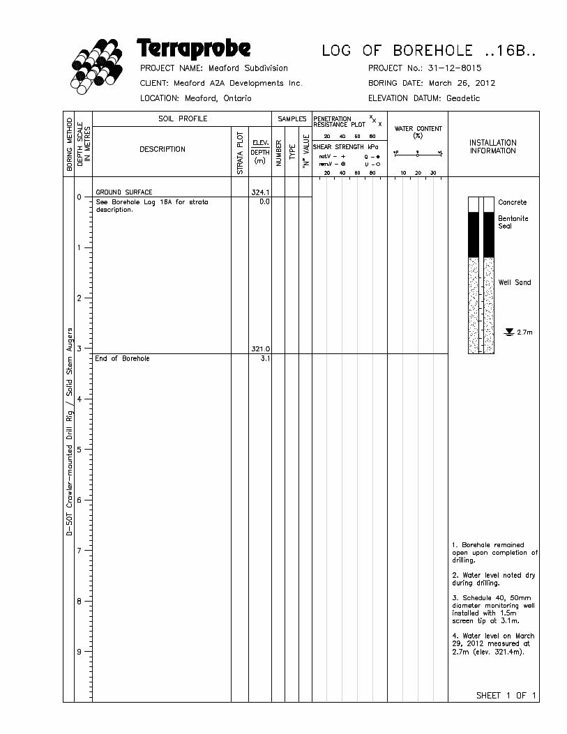
16A (deep) 324.1 5.5 318.6 5.6 318.5
16B (shallow) 324.1 Dry - 2.7 321.4
17 341.6 3.3 338.3 3.1 338.5
18 353.6 Dry - 4.0 349.6
19 347.0 1.8 345.2 1.6 345.4
20 341.2 5.5 335.7 2.0 339.2
It is anticipated that some fluctuations of the groundwater table will occur seasonally and may be higher
during wetter seasons and/or years. It is our recommendation that ongoing monthly monitoring of static

Proposed Residential Development, Meaford Highlands Resort, Meaford May 17, 2012
c/o Friedman & Associates File No. 31-12-8015
Terraprobe Page No. 6
groundwater levels continue through the spring/summer of 2012 as a minimum and preferably for a full year
in order to better define the seasonal fluctuation and peak levels. Shallow groundwater flow direction
appears to generally fall with surface topography from a high point in the central part of the site, along the
south property line, down towards the north, east and west. Shallow, overburden water levels generally fall
in elevation from about 350m (Borehole 18) to 314m (Borehole 1). The groundwater levels measured in the
deeper, bedrock monitoring wells indicate levels that are about 1.5 to 7m lower than the adjacent, overburden
water levels indicating a downward gradient on these upper table lands. A slightly artesian water level was
measured at Borehole 9.
It is our understanding that the soil and groundwater conditions encountered to date will also be utilized by
the clients civil, hydrogeological and environmental consultants as the design is refined.
6.0 DISCUSSION AND RECOMMENDATIONS
The following discussion and recommendations are based on the factual data obtained from this investigation
and are intended for use by the design engineers only. Contractors bidding on this project or conducting work
associated with this project should make their own interpretation of the factual data and/or carry out their
own investigations.
Generally, the site is underlain with stiff to hard native clayey silt soils over weathered shale bedrock.
6.1 Foundations
The undisturbed soils beneath the topsoil and/or any fill are considered suitable for the support of
conventional spread and/or strip footings for structures.
The very stiff to hard native conditions encountered below about 0.8m depth (i.e: typical ‘N’ values greater
than 20 blows per 0.3m of penetration) will allow structure foundations, etc. to be designed for a maximum
soil bearing pressure of 200kPa (SLS). A corresponding factored bearing capacity at Ultimate Limit State
(ULS) of approximately 300kPa may be used. Greater capacity may be available at greater depth if required
for specific resort/recreational components and can be assessed by Terraprobe on a case by case basis, if
required.

Proposed Residential Development, Meaford Highlands Resort, Meaford May 17, 2012
c/o Friedman & Associates File No. 31-12-8015
Terraprobe Page No. 7
A minimum soil cover of 1.5m or equivalent insulation is recommended for frost protection to footings in
exterior or unheated areas. Construction during cold weather should also ensure temporary frost protection
of footing bases.
The minimum footing widths to be used in conjunction with the above recommended soil bearing pressures
should be 0.5m for continuous footings and 0.8m for individual footings. The above recommended bearing
capacities are based on estimated maximum total settlement of 25 mm and differential settlement of 19mm.
It should also be noted that due to the variable conditions in the upper 1.0 to 2.0m of the site, some
downward stepping of footings should be anticipated in order to extend to competent soils.
Prior to placement of concrete for footings, the footing bases should be cleaned of all deleterious materials
such as topsoil, fill, softened or disturbed materials as well as any standing water. It is recommended that the
foundations be inspected by Terraprobe in order to confirm the exposed soil conditions and recommended
bearing capacities. If construction proceeds during freezing weather conditions, adequate temporary frost
protection for the footing bases and concrete must be provided.
Perimeter drainage measures for basements as per the Ontario Building Code should be implemented.
Areas of the property may require engineered fill to raise grades. This should be completed under full time
supervision by Terraprobe to monitor extent, lift thickness, compaction, material quality and the like.
Where structures are placed on at least 0.5m of engineered fill, the recommended maximum bearing capacity
may be 150 kPa. Engineered fill material may consist of granular type soils placed with moisture control in
maximum 150 mm loose lifts and compacted uniformly to a minimum of 98% of Standard Proctor Maximum
Dry Density. Terraprobe’s detailed engineered fill specifications will need to be followed if this option is
pursued.
6.2 Concrete Slab-On-Grade or Basement Floors
Conventional lightly loaded concrete slab-on-grade or basement floors can be placed on the existing native
inorganic soil subgrade below all deleterious materials, or on engineered fill placed under full time
supervision, provided a moisture break consisting of a minimum of 150 mm of OPSS Granular ‘A’ type

Proposed Residential Development, Meaford Highlands Resort, Meaford May 17, 2012
c/o Friedman & Associates File No. 31-12-8015
Terraprobe Page No. 8
material compacted to a minimum of 100% of Standard Proctor Maximum Dry Density (SPMDD) is placed
directly below the slab.
All basement floors should be constructed at least 0.3m above the seasonally high water level. Perimeter,
filtered, weeping drains must also be installed leading to positive outlets such as a sump pump in the
basement as per the current building code. Basement walls must be backfilled either with imported Granular
‘B’ type backfill or drainage mediums as per the Ontario Building Code. Basements may need to be raised
by the designers in some areas based on the groundwater levels measured to date.
Based on the magnitude and importance of this proposed development, we would strongly recommend
continued monthly monitoring of groundwater levels in the installed standpipes in order to support design
decisions (such as basement levels, deep excavations, etc.) as the design progresses.
6.3 Excavations
The recommended safe side slope configuration for temporary unbraced excavations above the groundwater
level through the native stiff to hard soils is 1 to 1 (horizontal to vertical) typically.
A Type 2 soil is characteristic of the site soils above the water level where 1 to 1 side slopes from 1.2m
above the base of the trench to ground surface should be used when workers must enter trenches deeper than
1.2m. Soils below the groundwater level are typically very dense overburden or shale and should be Type
2 also.
Excavations deeper than about 0.3m below the encountered water level where sandy seams are intercepted
may require localized sump pumping from widened trenches. Depending on excavation depths, a Permit to
Take Water from the MOE may be required for construction works at this site (ie: more than 50,000 litres
per day dewatering). These permits are currently taking several months to obtain. However, this is not
expected for the majority of the site.
The attached grain size analyses indicate permeabilities of the native clayey silt soils in the range of 10 to-7
10 cm/s.-8
Excavations are expected to be through stiff becoming hard cohesive silt grading into Queenston Shale.

Proposed Residential Development, Meaford Highlands Resort, Meaford May 17, 2012
c/o Friedman & Associates File No. 31-12-8015
Terraprobe Page No. 9
Large mechanical excavation equipment is anticipated to be required to conduct deeper cuts in particular.
As the site servicing plan is developed and advanced we would recommend that several test pits be excavated
on site to further evaluate the soil/rock excavation constraints.
6.4 Backfill
Based on our experience with silt to clayey silt soils, the water contents of the upper native site soils are
primarily in the range of 24 to 6% by weight. The estimated optimum water content for Standard Proctor
compaction is about 9 to 12%. Generally, soils can be sufficiently compacted at moisture contents up to
about 3% wetter than optimum. In this regard, a small portion of the upper native site soils fall within or
below this range and will be suitable for reuse as compacted fills during the construction process (ie: deeper
soils). Generally, the native soils will need to be mixed with drier soils or be wasted during the construction
process.
Earth fill materials placed beneath settlement sensitive areas such as floor slabs, sidewalks, pavement
structures and the like should be compacted to a minimum of 95% of Standard Proctor Maximum Dry
Density in lifts not exceeding 200mm.
The topsoil materials and organic rich sands encountered at the site should not be used as backfill in
settlement sensitive areas such as those noted above. The topsoil material may be stockpiled and reused for
landscaping purposes or wasted.
Should construction be conducted during the winter season, it is imperative to ensure that frozen materials
are not utilized as trench backfill.
It is recommended that inspection and testing be carried out by Terraprobe during construction to confirm
trench backfill quality, thickness and to ensure adequate compaction.
The majority of the excavated shale is anticipated to break down and can be reused as general backfill on site
for grading. Careful control is needed for replacing in trenches and/or confined backfill zones to ensure it
is “kneaded”/broken down into pieces less than 150mm in size. It is important to ensure a “void free” fill

Proposed Residential Development, Meaford Highlands Resort, Meaford May 17, 2012
c/o Friedman & Associates File No. 31-12-8015
Terraprobe Page No. 10
is created. Further assessment and recommendation from Terraprobe is recommended during construction
to provide specific recommendations.
6.5 Lateral Earth Pressures on Subsurface Walls
The boreholes encountered primarily cohesive silt to clayey silt soils, for the most part in a stiff to hard
condition within the upper 2 to 3m of ground surface.
For design of rigid concrete walls, the following design parameters are recommended.
Stiff to hard
soil unit weight ( 18.5 kN/m3
angle of internal friction M’ 30°
ocoefficient of lateral earth pressure “at rest” k 0.5
The recommended design angle of friction between concrete and the native soil is 24°. Associated with the
above is the inherent assumption that hydrostatic pressure will not be allowed to develop behind these wall
structures. In this regard, perimeter drainage systems will need to be implemented.
6.6 Pipe Bedding
Based on anticipated service inverts of about 2 to 4m below existing grade, the trench base is expected to
consist of stiff to hard silt to clayey silt and/or weathered shale. The undisturbed native soils encountered
at the site will generally be suitable for support of underground services with conventional Class ‘B’ granular
bedding. Additional granular bedding may be necessary for stabilization of wet trench bases. The granular
bedding should consist of a well graded material such as Granular ‘A’. Excavation bases should be free of
standing water prior to and during bedding and service placement.
Any soft, loose or disturbed soils encountered as a result of groundwater seepage or construction traffic
should be subexcavated and replaced with suitably compacted granular fill. Granular ‘A’ bedding material
should be placed in thin lifts and compacted to a minimum of 95% of SPMDD. If HL 8 course aggregate
or 19mm clear stone is used this will require light tamping only. However, it should be cautioned that this
HL8 aggregate or clear stone should not be used directly against native deposits unless a geotextile fabric

Proposed Residential Development, Meaford Highlands Resort, Meaford May 17, 2012
c/o Friedman & Associates File No. 31-12-8015
Terraprobe Page No. 11
is also considered as a complete wrap to prevent migration of fines into the bedding from the surrounding
fine soil.
6.7 Thrust Blocks and Pipe Restraints
It is recommended that the thrust blocks be cast directly against undisturbed native ground. The maximum
allowable bearing pressures for design of thrust blocks against undisturbed native soil where there is soil
cover over the block that equals the height of the block, is 200kPa.
The internal angle of friction between the thrust block and the soil may be taken as 33°.
The following design parameters are recommended for design of restrained joints;
! Ultimate friction angle between plastic or ductile iron pipe and
compact bedding 24°
! Ultimate friction angle between concrete pipe and
compact bedding 33°
! Maximum bearing of thrust pressure of pipe normal
to bedding against native soil 200 kPa
6.8 Pavement Design Thickness
The pavement subgrade is expected to comprise of a silt to clayey silt in most cases or perhaps clean earth
fill compacted to a minimum of 95% of SPMDD. The exposed subgrade should be shaped and graded with
a typical 3% cross-fall, directed towards continuous subdrains and/or open ditches with inverts at least 0.3m
below subgrade level.
The pavement subgrade should be proof rolled to evaluate its stability. All unstable areas will require sub-
excavation and re-compaction or increased thickness of granular subbase. It should be noted that the majority
of the upper site soils are considered somewhat frost susceptible. Therefore, adequate subgrade drainage is
recommended.
Based on the soil conditions encountered during our investigation, we recommend that a sufficient pavement
structure for internal, local roads will be as follows;

Proposed Residential Development, Meaford Highlands Resort, Meaford May 17, 2012
c/o Friedman & Associates File No. 31-12-8015
Terraprobe Page No. 12
HL 3 (surface) asphalt 40 mmHL 8 (binder) asphalt 50 mmOPSS Granular ‘A’ (base course) 150 mmOPSS Granular ‘B’ (subbase course) 400 mmTotal 640 mm
The above design assumes that sub-drainage of the granular fill will be provided. This should consist of
continuous subdrains leading to catch basins and/or open ditches.
It should be reiterated that the subgrade soils are frost susceptible. The subdrains are considered a valuable
protection against frost heave damage and subgrade softening particularly impacting the long term
performance of the pavement.
All topsoil and any organic-rich material should be removed from below settlement sensitive areas such as
pavements. Immediately prior to placement of the pavement granular courses, the subgrade should be proof
rolled with a heavy rubber tired vehicle (such as a grader) and any loose, soft or unstable areas should be
subexcavated and backfilled with compacted materials.
The granular subbase and base fill materials should be compacted to a minimum of 100% of Standard Proctor
Maximum Dry Density (SPMDD), placed in lifts of 150 mm or less. Asphaltic concrete materials should be
rolled and compacted to a minimum of 97% of Marshall Bulk Density (MBD) based on nuclear density
testing.
The above pavement design thicknesses are considered adequate for the design traffic. However, if pavement
construction occurs in wet inclement weather it may be necessary to provide additional subgrade support for
heavy construction traffic by increasing the thickness of the granular subbase or base course materials.
Further, main traffic access areas for construction equipment may experience unstable subgrade conditions.
These may need stabilization utilizing additional thickness of granular materials.
It is recommended that inspection and testing be carried out during construction to confirm material quality,
thickness and to ensure adequate compaction.

Proposed Residential Development, Meaford Highlands Resort, Meaford May 17, 2012
c/o Friedman & Associates File No. 31-12-8015
Terraprobe Page No. 13
6.9 Earthquake Design Parameters
The Ontario Building Code (2006) stipulates the methodology for earthquake design analysis, as set out in
Subsection 4.1.8.7. The determination of the type of analysis is predicated on the importance of the
structure, the spectral response acceleration and the site classification.
The parameters for determination of Site Classification for Seismic Site Response are set out in Table
4.1.8.4A of the Ontario Building Code (2006). The classification is based on the determination of the
saverage shear wave velocity in the top 30 metres of the site stratigraphy, where shear wave velocity (v )
measurements have been taken. Alternatively, the classification is estimated on the basis of rational analysis
uof undrained shear strength (s ) or penetration resistance.
At this site the stratigraphy beneath the buildings will consist of at least 9.6 metres of soil with a penetration
resistance averaging at least 50 to 60 blows per 300 mm. The soils are primarily hard clayey silt to shale at
depth. It is known that the deeper stratigraphy in this area is at least as competent. On this basis, the site
designation for seismic analysis is Class C, according to Table 4.1.8.4.A of the Ontario Building Code
(2206). Tables 4.1.8.4B and 4.1.8.4C of the same code provide the applicable acceleration and velocity
based site coefficients.
aSite Class Values of F
a a a a aS (0.2) # 0.25 S (0.2) = 0.50 S (0.2) = 0.75 S (0.2) = 1.00 S (0.2) $ 1.25
C 1.0 1.0 1.0 1.0 1.0

Proposed Residential Development, Meaford Highlands Resort, Meaford May 17, 2012
c/o Friedman & Associates File No. 31-12-8015
Terraprobe Page No. 14
vSite Class Values of F
a a a a aS (1.0) # 0.1 S (1.0) = 0.2 S (1.0) = 0.3 S (1.0) = 0.4 S (1.0) $ 0.5
C 1.0 1.0 1.0 1.0 1.0
6.10 Stormwater Management Facilities
Boreholes 3, 6, 12 and 16 were advanced in or near the proposed storm pond areas as shown approximately
on Figures 2 and 3.
It is our understanding that the pond proposed in the area of Borehole 3 will be a wet facility, while the
remaining SWM ponds will be dry facilities.
The pond designs have not been completed at the time of this investigation. However, based on the soils
encountered, we would not anticipate that the ponds will need to be lined.
The attached reports indicate grain size analyses for the different strata encountered in these boreholes.
Based on the above, we would expect the proposed ponds to be situated in stiff to hard clayey silt to
weathered shale. We would estimate a coefficient of permeability of about 10 to 10 cm/s in the silt to-7 -8
clayey silt grading to weathered shale.
Pond geometry of 4:1 (horizontal to vertical) internal side slopes are appropriate below the normal high
groundwater level for the type and density of the soils encountered during our investigation. Additional
monitoring would be required to confirm groundwater levels. Interior slopes above the normal high water
level could be constructed to a maximum of 3:1 (horizontal to vertical). Exterior berm slopes may be created
to 3:1 which will also be suitable from a geotechnical perspective depending on whether maintenance and/or
grass cutting will be required on the slopes.
It is our understanding that runoff from the site will be collected and directed to stormwater management
ponds through lined channels before being released in a controlled manner to suitably protected discharge
points.

Proposed Residential Development, Meaford Highlands Resort, Meaford May 17, 2012
c/o Friedman & Associates File No. 31-12-8015
Terraprobe Page No. 15
6.11 Soil Chemistry Analysis
As requested, Terraprobe has collected topsoil samples for pesticide analysis further to the Phase One ESA
conducted for this site. The details of the sampling and testing are reported under separate cover by
Terraprobe.
6.12 Slope Stability Analysis and Development Setbacks
Terraprobe has conducted a comprehensive slope stability study based on the subsurface findings of this
investigation. The results of this assessment and the recommended development setbacks are reported under
separate cover by Terraprobe.
7.0 CONCLUSIONS
Terraprobe was retained to provide preliminary geotechnical characterization of the site and to provide
recommendations based on these findings to guide design decisions.
Terraprobe observed and recorded the advancement of twenty (20) sampled boreholes on the subject
property. The boreholes generally indicated stiff to hard silt to clayey silt overburden soils in the upper 2
to 5m across the site, grading into hard, weathered Queenston Formation Shale with depth. As noted above,
groundwater levels were measured once at the end of March in the installed standpipes/monitoring wells with
levels recorded from 9m below grade to 0.1m above existing grade.
Groundwater monitoring wells were installed at select locations as specified by Cole Engineering to assist
their hydrogeologic study.
Due to the density of the encountered soil and/or bedrock, it is our opinion that excavations will require
large, mechanical equipment in order to break up the hard conditions. The soil/rock excavation constraints
should be further assessed with additional test pit investigation as the design proceeds and proposed
excavation depths and locations are better understood. This will also assist with a better understanding of
groundwater ingress and potential for temporary dewatering required during construction.
It is recommended that groundwater monitoring in the installed monitoring wells/standpipes should continue
on a monthly basis in order to evaluate the magnitude of seasonal groundwater fluctuations and estimate peak


BOREHOLE LOGS Terraprobe Inc.

Terraprobe ABBREVIATIONS, TERMINOLOGY,
GENERAL INFORMATION
BOREHOLE LOGS
SAMPLING METHOD
SS split spoon
ST Shelby tube
AS auger sample
W S wash sample
RC rock core
W H weight of hammer
PH pressure, hydraulic
PENETRATION RESISTANCE
Standard Penetration Test (SPT) resistance (‘N’ values) is defined as the
number of blows by a hammer weighing 63.6 kg (140 lb.) falling freely for a
distance of 0.76 m (30 in.) required to advance a standard 50 mm (2 in.) diameter
split spoon sampler for a distance of 0.3 m (12 in.).
Dynamic Cone Test (DCT) resistance is defined as the number of blows by a
hammer weighing 63.6 kg (140 lb.) falling freely for a distance of 0.76 m (30 in.)
required to advance a conical steel point of 50 mm (2 in.) diameter and with 60°
sides on ‘A’ size drill rods for a distance of 0.3 m (12 in.).
SOIL DESCRIPTION - COHESIONLESS SOILS
Relative Density ‘N’ value
very loose < 4
loose 4 - 10
compact 10 - 30
dense 30 - 50
very dense > 50
SOIL DESCRIPTION - COHESIVE SOILS
Consistency Undrained Shear ‘N’ value
Strength, kPa
very soft < 12 < 2
soft 12 - 25 2 - 4
firm 25 - 50 4 - 8
stiff 50 - 100 8 - 16
very stiff 100 - 200 16 - 32
hard > 200 > 32
SOIL COMPOSITION
% by weight
‘trace’ (e.g. trace silt) < 10
‘some’ (e.g. some gravel) 10 - 20
adjective (e.g. sandy) 20 - 35
‘and’ (e.g. sand and gravel) 35 - 50
TESTS, SYMBOLS
MH mechanical sieve and hydrometer analysis
cw, w water content
lw liquid limit
pw plastic limit
pI plasticity index
k coefficient of permeability
( soil unit weight, bulk
N ’ angle of internal friction
c’ cohesion shear strength
cC compression index
GENERAL INFORMATION, LIMITATIONS
The conclusions and recommendations provided in this report are based on the factual information obtained from
the boreholes and/or test pits. Subsurface conditions between the test holes may vary.
The engineering interpretation and report recommendations are given only for the specific project detailed within,
and only for the original client. Any third party decision, reliance, or use of this report is the sole and exclusive
responsibility of such third party. The number and siting of boreholes and/or test pits may not be sufficient to
determine all factors required for different purposes.
It is recommended Terraprobe be retained to review the project final design and to provide construction
inspection and testing.
Abbrev.wpd


GRAIN SIZE ANALYSIS Terraprobe Inc.

Terraprobe SIEVE AND HYDROMETER ANALYSIS
TEST REPORTPROJECT: Meaford Subdivision
LOCATION: Meaford, ON FILE NO.: 31-12-8015CLIENT: Meaford A2A Developments Inc. LAB NO.: 1514a
c/o Friedman & Associates SAMPLE DATE: Apr-03-12BOREHOLE NUMBER: 1 SAMPLE DEPTH: N/G SAMPLED BY: B.H.
SAMPLE NUMBER: 2SAMPLE LOCATION: as above
SAMPLE DESCRIPTION: Silt, some clay, some sand, trace gravel
U.S. STANDARD SIEVE SIZES
0
10
20
30
40
50
60
70
80
90
100
0.00010.0010.010.1110100
GRAIN SIZE (mm)
PE
RC
EN
T P
AS
SIN
G (
%)
0
10
20
30
40
50
60
70
80
90
100
PE
RC
EN
T R
ET
AIN
ED
(%
)
3/4"1.5" 3/8" #4 #20 #60 #200
'''''''#10
'#40
' '#140
GRAIN SIZE DISTRIBUTION
GRAIN SIZE CONTENTUnified System
Gravel……………....9%Sand……………….15%Silt and Clay………76%
UNIFIED SYSTEM GRAVEL SAND SILT AND CLAY
MEDIUM FINE COARSE FINE COARSE
MITSYSTEM GRAVEL SAND SILT
MEDIUM FINE COARSE
CLAY

Terraprobe SIEVE AND HYDROMETER ANALYSISTEST REPORT
PROJECT: Meaford SubdivisionLOCATION: Meaford, ON FILE NO.: 31-12-8015
CLIENT: Meaford A2A Developments Inc. LAB NO.: 1514bc/o Friedman & Associates SAMPLE DATE: Apr-03-12
BOREHOLE NUMBER: 6 SAMPLE DEPTH: N/G SAMPLED BY: B.H.SAMPLE NUMBER: 4
SAMPLE LOCATION: as aboveSAMPLE DESCRIPTION: Clayey silt, trace sand
U.S. STANDARD SIEVE SIZES
0
10
20
30
40
50
60
70
80
90
100
0.00010.0010.010.1110100
GRAIN SIZE (mm)
PE
RC
EN
T P
AS
SIN
G (
%)
0
10
20
30
40
50
60
70
80
90
100
PE
RC
EN
T R
ET
AIN
ED
(%
)
3/4"1.5" 3/8" #4 #20 #60 #200
''''''#10
'#40
' '#140
GRAIN SIZE DISTRIBUTION
GRAIN SIZE CONTENTUnified System
Gravel……………....0%Sand………………..8%Silt and Clay………92%
UNIFIED SYSTEM GRAVEL SAND SILT AND CLAY
MEDIUM FINE COARSE FINE COARSE
MITSYSTEM GRAVEL SAND SILT
MEDIUM FINE COARSE
CLAY

Terraprobe SIEVE AND HYDROMETER ANALYSISTEST REPORT
PROJECT: Meaford SubdivisionLOCATION: Meaford, ON FILE NO.: 31-12-8015
CLIENT: Meaford A2A Developments Inc. LAB NO.: 1514cc/o Friedman & Associates SAMPLE DATE: Apr-03-12
BOREHOLE NUMBER: 16 SAMPLE DEPTH: N/G SAMPLED BY: B.H.SAMPLE NUMBER: 7
SAMPLE LOCATION: as aboveSAMPLE DESCRIPTION: Clayey silt, trace sand
U.S. STANDARD SIEVE SIZES
0
10
20
30
40
50
60
70
80
90
100
0.00010.0010.010.1110100
GRAIN SIZE (mm)
PE
RC
EN
T P
AS
SIN
G (
%)
0
10
20
30
40
50
60
70
80
90
100
PE
RC
EN
T R
ET
AIN
ED
(%
)
3/4"1.5" 3/8" #4 #20 #60 #200
''''''#10
'#40
' '#140
GRAIN SIZE DISTRIBUTION
GRAIN SIZE CONTENTUnified System
Gravel……………....0%Sand……………….10%Silt and Clay………90%
UNIFIED SYSTEM GRAVEL SAND SILT AND CLAY
MEDIUM FINE COARSE FINE COARSE
MITSYSTEM GRAVEL SAND SILT
MEDIUM FINE COARSE
CLAY

Terraprobe SIEVE AND HYDROMETER ANALYSISTEST REPORT
PROJECT: Meaford SubdivisionLOCATION: Meaford, ON FILE NO.: 31-12-8015
CLIENT: Meaford A2A Developments Inc. LAB NO.: 1514dc/o Friedman & Associates SAMPLE DATE: Apr-03-12
BOREHOLE NUMBER: 5 SAMPLE DEPTH: N/G SAMPLED BY: B.H.SAMPLE NUMBER: 3
SAMPLE LOCATION: as aboveSAMPLE DESCRIPTION: Clayey silt, trace sand
U.S. STANDARD SIEVE SIZES
0
10
20
30
40
50
60
70
80
90
100
0.00010.0010.010.1110100
GRAIN SIZE (mm)
PE
RC
EN
T P
AS
SIN
G (
%)
0
10
20
30
40
50
60
70
80
90
100
PE
RC
EN
T R
ET
AIN
ED
(%
)
3/4"1.5" 3/8" #4 #20 #60 #200
''''''#10
'#40
' '#140
GRAIN SIZE DISTRIBUTION
GRAIN SIZE CONTENTUnified System
Gravel……………....0%Sand………………...4%Silt and Clay………96%
UNIFIED SYSTEM GRAVEL SAND SILT AND CLAY
MEDIUM FINE COARSE FINE COARSE
MITSYSTEM GRAVEL SAND SILT
MEDIUM FINE COARSE
CLAY

Terraprobe SIEVE AND HYDROMETER ANALYSISTEST REPORT
PROJECT: Meaford SubdivisionLOCATION: Meaford, ON FILE NO.: 31-12-8015
CLIENT: Meaford A2A Developments Inc. LAB NO.: 1514ec/o Friedman & Associates SAMPLE DATE: Apr-03-12
BOREHOLE NUMBER: 12 SAMPLE DEPTH: N/G SAMPLED BY: B.H.SAMPLE NUMBER: 7
SAMPLE LOCATION: as aboveSAMPLE DESCRIPTION: Silt, some clay, trace sand, trace gravel
U.S. STANDARD SIEVE SIZES
0
10
20
30
40
50
60
70
80
90
100
0.00010.0010.010.1110100
GRAIN SIZE (mm)
PE
RC
EN
T P
AS
SIN
G (
%)
0
10
20
30
40
50
60
70
80
90
100
PE
RC
EN
T R
ET
AIN
ED
(%
)
3/4"1.5" 3/8" #4 #20 #60 #200
''''''#10
'#40
' '#140
GRAIN SIZE DISTRIBUTION
GRAIN SIZE CONTENTUnified System
Gravel……………....1%Sand………………...7%Silt and Clay………92%
UNIFIED SYSTEM GRAVEL SAND SILT AND CLAY
MEDIUM FINE COARSE FINE COARSE
MITSYSTEM GRAVEL SAND SILT
MEDIUM FINE COARSE
CLAY

Terraprobe SIEVE AND HYDROMETER ANALYSIS
TEST REPORTPROJECT: Meaford Subdivision
LOCATION: Meaford, ON FILE NO.: 31-12-8015CLIENT: Meaford A2A Developments Inc. LAB NO.: 1514f
c/o Friedman & Associates SAMPLE DATE: Apr-03-12BOREHOLE NUMBER: 18 SAMPLE DEPTH: N/G SAMPLED BY: B.H.
SAMPLE NUMBER: 3SAMPLE LOCATION: as above
SAMPLE DESCRIPTION: silt and clay, trace sand
U.S. STANDARD SIEVE SIZES
0
10
20
30
40
50
60
70
80
90
100
0.00010.0010.010.1110100
GRAIN SIZE (mm)
PE
RC
EN
T P
AS
SIN
G (
%)
0
10
20
30
40
50
60
70
80
90
100
PE
RC
EN
T R
ET
AIN
ED
(%
)
3/4"1.5" 3/8" #4 #20 #60 #200
'''''''#10
'#40
' '#140
GRAIN SIZE DISTRIBUTION
GRAIN SIZE CONTENTUnified System
Gravel……………....0%Sand………………...1%Silt and Clay………99%
UNIFIED SYSTEM GRAVEL SAND SILT AND CLAY
MEDIUM FINE COARSE FINE COARSE
MITSYSTEM GRAVEL SAND SILT
MEDIUM FINE COARSE
CLAY

FIGURES
Terraprobe Inc.


