tensile and cyclic fatigue properties of graphite filament-wound
TRANSCRIPT

N A S A TECHNICAL NOTE
.cr m m m
I n z c 4 r/) 4 z
- N A S A T_N do /
D-5354
LOAN COPY: RETURN TO
KIRTLANQ AFB, N M U AFWL [Vv'klL-2)
TENSILE A N D CYCLIC FATIGUE PROPERTIES OF GRAPHITE FILAMENT-WOUND PRESSURE VESSELS AT AMBIENT A N D CRYOGENIC TEMPERATURES
by Morgun P. Hunson
Lewis Reseurcb Center C Zeve Zmd, Ohio
N A T I O N A L A E R O N A U T I C S A N D SPACE A D M I N I S T R A T I O N W A S H I N G T O N , D. C. J U L Y 1 9 6 9
https://ntrs.nasa.gov/search.jsp?R=19690021922 2018-02-14T02:10:09+00:00Z

TECH LIBRARY KAFB, NM
I111111 11111 IHI 11111 lllll111ll111ll Ill 111 0 13 2 3 0 8
TENSILE AND CYCLIC FATIGUE PROPERTIES OF GRAPHITE
FILAMENT-WOUND PR;ESSURE VESSELS AT AMBIENT
AND CRYOGENIC TEMPERATURES
By Morgan P. Hanson
Lewis Research Center Cleveland, Ohio
NATIONAL AERONAUTICS AND SPACE ADMINISTRATION
For solo by tho Cloaringhouso for Federal Scientific and Technical lnformotion Springfiold, Virginia 22151 - CFSTI prico $3.00

ABSTRACT
Graphite f ibers were fabricated into NOL rings and biaxial-wound cylinders. Fila- ment tensile strengths of NOL rings were determined at 75O, -320°, and -423' F (297, 71, and 20 K). Comparisons were made of ambient-temperature fiber tensile strengths as obtained from NOL r ings, strand tes ts , and biaxially wound cylinders. character is t ics of internally pressurized cylinders were determined at 75' and -320' F (291 and 77 K). cylinders on the basis of specific strength.
Fatigue
Fatigue comparisons a r e made of graphite and glass-filament wound
ii

TENSILE AND CYCLIC FATIGUE PROPERTIES OF GRAPHITE FILAMENT-WOUND
PRESSURE VESSELS AT AMBIENT AND CRYOGENIC TEMPERATURES
/ by Morgan P. Hanson
Lewis Research Center
SUMMARY
An experimental investigation was conducted to determine the tensile and fatigue properties of graphite-reinforced epoxy composites. Thornel-50 was used as the graphite-filament reinforcement. The graphite f ibers were fabricated into Naval Ord- nance Laboratory (NOL) rings and biaxial-wound cylinders. Filament tensile strengths of NOL rings were determined at 75O, -320°, and -423' F (297, 77, and 20 K). Compar- isons were made of ambient-temperature fiber tensile strengths as obtained from NOL rings, strand tests, and biaxially wound cylinders. Fatigue characterist ics of internally pressurized cylinders were determined at 75" and -320' F (297 and 77 K). Fatigue comparisons are made of graphite and glass filament-wound cylinders on the basis of specific strength.
INTRODUCTION
Graphite fibers having high specific-strength and modulus properties are of particu- lar interest in aerospace applications. The use of graphite fibers in an epoxy matrix as a structural material has been demonstrated (refs. 1 and 2). As a structural material in filament-wound pressure vessels, graphite fibers should provide a solution to problems that a r e inherent to low-modulus reinforcements such as glass fibers. In high performance glass filament-wound pressure vessels, buckling and fatigue of metallic l iners occur because of large plastic strains (2 to 3 percent) (ref. 3).
In a practical application, pressure vessels are subjected to long-term pressuriza- tion and periodic pressure cycling. Under these conditions at ambient temperature, the use of glass filament-wound pressure vessels has been found to be restricted because of the combined effects of low static fatigue and cyclic fatigue properties (refs. 4 and 5). Results in reference 6 show that the fatigue life of unidirectionally s t ressed graphite-
I
I
Tensile
epoxy composites at ambient temperature is superior to that of glass fibers. In bi- axially s t ressed pressure vessels s imilar results may be expected. At cryogenic tem- peratures information on the static and cyclic fatigue behavior of filament-wound pres- s u r e vessels is limited. A review on the subject in reference 7 indicates that fatigue life of glass-filament composites may not be limited at cryogenic temperatures. However, from a practical consideration, good fatigue properties at ambient temperature would be required from the standpoint of reliability.
cylinders was conducted at the NASA Lewis Research Center. Cylinders of Thornel-50 were pressure cycled at ambient temperature (75' F o r 297 K) and in liquid nitrogen (-320' F or 77 K). The tensile strength of Thornel-50 was determined by means of NOL ring and strand tests. NOL rings were tested at 75O, -320°, and -423' F (297, 77, and 20 K). Strand tests were performed at ambient temperature.
An investigation of the cyclic behavior of filament-wound graphite -reinforced
NOL ring
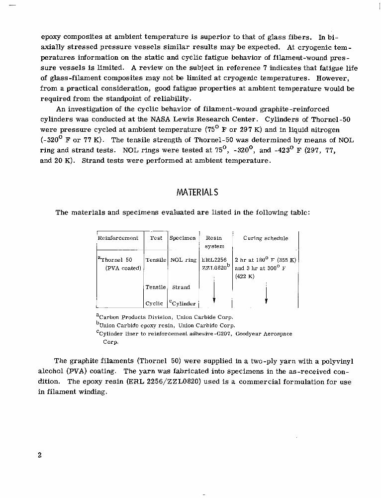
MATERIALS
Cyclic
The materials and specimens evaluated are listed in the following table:
$- 'Cylinder
lReinforcement I aThornel 50
(PVA coated)
Tensile 1 Strand
Resin system
ERL2256 Z Z LO 820b
Curing schedule
2 h r at 180' F (355 K) and 3 h r at 300' F (422 K)
aCarbon Products Division, Union Carbide Corp. Carbide epoxy res in , Union Carbide Corp.
'Cylinder liner to reinforcement adhesive -G207, Goodyear Aerospace Corp.
The graphite filaments (Thornel 50) were supplied in a two-ply yarn with a polyvinyl alcohol (PVA) coating. The yarn was fabricated into specimens in the as-received con- dition. The epoxy resin (ERL 2256/ZZLO820) used is a commercial formulation for use in filament winding.
2

APPARATUS AND PROCEDURE
Tensi le Tests
NOL rings. - Naval Ordnance Laboratory (NOL) rings of two-ply graphite yarn were wet wound under 0.5-pound (2.22-N) tension with 100 turns per ring. The rings were then cured according to the schedule in the previous section. No surface machining was performed on the rings. Tensile strength tests were made at ambient and cryogenic temperatures using split disk fixtures. The cryogenic temperatures were established by submersion of specimens in liquid nitrogen (-320' F or 77 K) or liquid hydrogen (-423' F o r 20 K) in special cryostats mounted in a universal tensile machine. The load was applied at crosshead rate of 0 .1 inch (2.5 mm) per minute. The filament tensile strength of the composite was based on the load per unit area of the two-ply yarn. The fiber cross-sectional area was determined by dividing the average weight of a unit length
3 of yarn by the density of the Thornel-50 graphite (0.059 lbm/in. or 1 .63 g/cm ). An average 68-percent fiber volume was determined for the NOL rings. The burnout method used is described in reference 1.
cured. and attached with an epoxy adhesive. The gage length was 2 inches .(50.8 mm). The s t rands were tested in a universal tensile machine at a crosshead travel rate of 0.05 inch (1.27 mm) per minute. using the method described in the previous section.
Strand tests. - Individual strands of two-ply yarn were impregnated with resin and ___- Lengths of the impregnated yarn were placed in grooved metal end tabs, alined,
The filament tensile strength of the composite was determined
Cyc l ic Tests of Fi lament-Wound Cy l inders
The cylinders used fo r cyclic tes ts were right circular cylinders, 7.5 inches (19.1 cm) in diameter by 20 inches (50.8 cm) long. The cylinders were lined with 3-mil (0.076-mm) 1100-0 aluminum foil with a 0.25-inch (6.35-mm) adhesive-bonded lap seam. A polyester res in (G207) was used as the adhesive in the seam and between the liner and the adjacent hoop windings. The ratio of the hoop to longitudinal windings was 2 to 1 with an arrangement of inner and outer hoop windings and a single longitudinal layer in between. Both the hoop and longitudinal windings of two-ply yarn were spaced at 52 turns p e r inch (20. 5 turns p e r centimeter).
The cylinders were fabricated on mandrels of thick-wall aluminum tubing. diametral taper was provided to facilitate removal of the finished cylinder from the
Resin was brushed on during winding. A slight
3

Fi l l and ,-Vent and pressure pressurization: ,’ measurement
Figure 1. - Schematic diagram of biaxial cylinder wi th removable end caps used for cyclic tests. (Dimensions are in inches (cm). 1
mandrel. reference 3.
The type of caps used for closing the ends of the cylinders is shown in figure 1. This method was also used and described in reference 3. A low-melting-point alloy filled the groove, effectively locking and sealing the end caps to allow pressurization. At ambient temperature, the cylinders were pressurized with oil and cycled at a rate of about 2 cycles per minute. In liquid nitrogen testing, both inner and outer surfaces of the cylinders were exposed to the cryogen. A liquid-nitrogen pump was used for pres- surization. The cyclic rate was about 3 cycles per minute. In both the ambient and cryogenic cyclic testing, the pressure ranged from a low of about 50 ps i (34. 5 N/cm ) to a maximum depending on the percent of predicted burst p ressure required for the partic- u la r test. Maximum pressures ranged from 350 to 400 psi (241 t o 276 N/cm ).
Hoop and longitudinal strains were measured by means of electric resistance s t ra in gages mounted on the cylinder surface and also by means of deflection transducers. The s t ra in gages were of Nichrome V alloy and were used at both ambient and liquid-nitrogen temperatures. The adhesively bonded s t ra in gage was used for precise s t ra in measure- ment in the initial cycles. Under cyclic loading, the bonded strain-gage. life was m- predictable. Therefore, the deflection transducers were used for continuous strain observations. The hoop strain was sensed by means of a 10-mil (0.25-mm) wire c i r - cumscribing the cylinder at the midpoint of the test section. The longitudinal s t ra in was measured similarily between clips adhesively bonded to the cylinder wall. An installa- tion is shown in figure 2.
Complete details of liner assembly and genera1 construction a r e presented in
2
2
4

---~ ---------,,------ -~-----~ - ---- -
Longitudinal strai n instrumentation
Hoop-strain -----1 instru mentation /
I \
Figure 2. - Test cyl inder with instrumentation for measuring longitudinal and hoop strains.
The filament stress of the composite was determined from the internal pressure,
cylinder dimensions, and the cross-sectional area of the two-ply yarn. No fiber volume
was determined for the cylinders; however , it is believed to be lower than that of the
NOL rings because of the yarn spacing between hoop and longitudinal windings.
RESULTS AND DISCUSSION
Strength Characteristics of Graphite Filaments
Figure 3 shows the average filament tensile strength of composites of NOL rings as
a function of temperature. The number of specimens tested at each temperature are
indicated. Also shown is the range of the test data. No Significant change in average
strength is noted for the Thornel-50 throughout the temperature range investigated. A similar trend was noted for Thornel-25 in reference 3.
Table I lists composite filament tensile strength results of fiber , strand, NOL ring,
and cylinder tests at ambient temperature. Single-fiber tensile strength of 293 000 psi
(202 000 N/ cm 2) agreed favorably with the strand tensile strength of 290 000 psi
(200 000 N/ cm 2). The filament strength of NOL rings was 229 000 psi (158 000 N/ cm 2)
and of cylinders was 219 000 psi (151 000 N/ cm 2). The lower filament strength of rings
5
J
·1

N
.- VI
250
c VI a,
v) c a,
c a, m
.- w zoo .- UI c W
c
c c
c E
L 5 150. 100 ~
Y
2 2 5 ~ 1 0 ~
2 44
207
204
T
155x10'
168
143
141
I (15)
100 ' -423 -320
I 15
Temperature, "F
I 297
L 20 77
Temperature, K
Figure 3. - Filament strength of graphite NOL r ings as a funct ion of temperature. Numbers in parentheses indicate the number of tests for each temperature.
TABLE I. - AMBIENT TEMPERATURE FILAMENT STRENGTH O F
THORNEL-50 AS DETERMINED BY DIFFERENT TEST METHODS
bJ 'Cylinder
Tensile strength
Aver age Maximum
ps i 1 N/cm2
274 I 189 233 I161
'Determined by the manufacturer on single fiber. bImpregnated with epoxy res in and cured. 'Burst tests at -320' F (77 K) resulted in average tensile stress of
218 000 ps i (150 000 N/cm2).
6

and cylinders possibly reflects the greater frequency of voids, flaws, and influence of low shear transfer between plies of yarn when the material is essentially in laminated form. Nevertheless, the filament translation efficiency of 77 percent is higher than that generally found in glass composites (for S/901 glass, 69 percent and for E glass, 61 per- cent (ref. 3)). NOL rings of Thornel-25 in reference 3 gave an average translation effi- ciency of 67 percent. Some of the scatter in strength data of the Thornel-50 investigated can be attributed to the variation in material properties from seven different spools.
Hoop strain. percent
Figure 4. - Stress-strain diagram for single-cycle test of Thornel-50 epoxy res in cylinder. Filament tensile modulus, 48. 8x10⁶ psi (33.5~106 Nlcm2).
Figure 4 shows a typical filament s t ress-s t ra in diagram of the hoop windings of a cylinder at ambient temperature. It is seen that the relation is linear up to a fracture s t ra in of 0.48 percent. The filament tensile modulus was determined to be 48. 8x10 psi (33.5x10 N/cm ) which is in good agreement with the nominal modulus of Thornel-50. No significant change in tensile modulus was found at liquid-nitrogen temperature. All tensile moduli measurements were within manufacturing tolerance of the material.
6 6 2
>
Cyc l ic Charac ter is t i cs of G raphi te-Fi lament Wound Cy1 inde rs ‘*
Cyclic fatigue degradation has been of concern in filament-wound pressure vessels. This has been particularly true of glass-filament-wound pressure vessels (ref. 4). The failure mechanism in cyclic loading of these vessels, however, may not be limited only to the accumulated number of cycles. The degradation effect of water vapor on glass has been shown to influence fatigue characteristics; in reference 7 it was pointed out that time under load may be the predominate cause of the failure of glass filaments. However, a normalization of the static and cyclic data in reference 7 indicate that combined effects of static and cyclic fatigue are responsible for the failure mechanism. In the present in-
7

Temperature, Cycles per "F (K) minute 75 (297) 2
-320 177) 3
60 -
1000 10000 Cycles
Figure 5. - Comparison of cyclic fatigue of glass and graphite filament-wound cylinders.
vestigation, failure of the graphite cylinders is presented only on the basis of the number of cycles to failure. The mechanisms that influence fatigue in glass filaments may not be those operative in graphite. In reference 6 it was reported that prolonged water boil of Thornel-25 and Thornel-40 epoxy-resin composites did not result in substantial decrease in flexural properties.
In figure 5, cyclic fatigue is presented for Thornel-50 graphite filament-wound cylinders as a percent of the single-cycle burst strength. Data are shown at 75' F (297 K) and at -320' F (77 K). It is seen that fatigue life at -320' F (77 K) was similar to that at '75' F (297 K). Also shown is a comparison of the 75' F (297 K) fatigue life of glass-filament-wound pressure vessels from reference 4. Direct comparison of fatigue life appears to be reasonable since tests were performed at essentially the same cyclic r a t e s (2 to 4 cycles per minute). The results are in good agreement to the superior uniaxial fatigue properties of graphite compared with those of glass as reported in refer- ence 6.
The performance of the liner was relevant to the overall performance of the graphite- filament-wound cylinder. Visual examination of the 3-mil (0.076-mm) aluminum liners after cyclic failure showed no evidence of buckling even though the aluminum was strained plastically (about 0 .4 percent under cyclic load). No termination of a cyclic test resulted from liner failure. ments.
4
*
Termination of cyclic tests was the result of failure of the hoop fila-
Because of the inherent high strength of glass filaments, it is of interest to compare Some tests were discontinued because of time limitations.
the ambient temperature fatigue characteristics of glass and graphite-filament-wound
8
! +
10 100 loo0 10,000 Cycles
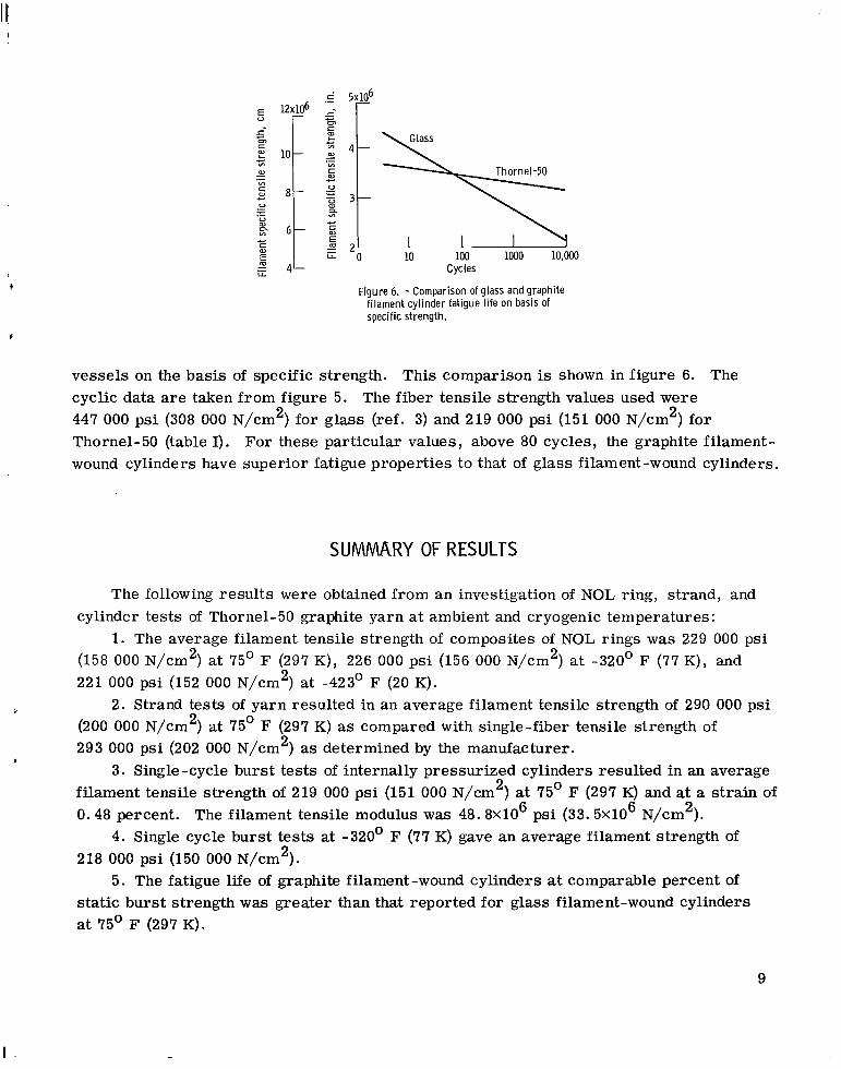
Figure 6. - Comparison of glass and graphite filament cyl inder fatigue l l fe on basis of specific strength.
vessels on the basis of specific strength. This comparison is shown in figure 6. The cyclic data are taken from figure 5. The fiber tensile strength values used were 447 000 psi (308 000 N/cm2) for glass (ref. 3) and 219 000 psi (151 000 N/cm2) for Thornel-50 (table I). For these particular values, above 80 cycles, the graphite filament- wound cylinders have superior fatigue properties to that of glass filament-wound cylinders.
SUMMARY OF RESULTS
The following resul ts were obtained from an investigation of NOL ring, strand, and
1. The average filament tensile strength of composites of NOL rings was 229 000 psi cylinder tests of Thornel-50 graphite yarn at ambient and cryogenic temperatures :
(158 000 N/cm2) at 75' F (297 K), 226 000 psi (156 000 N/cm2) at -320' F (77 K), and 221 000 psi (152 000 N/cm2) at -423' F (20 K).
(200 000 N/cm ) at 75' F (297 K) as compared with single-fiber tensile strength of 293 000 psi (202 000 N/cm2) as determined by the manufacturer.
filament tensile strength of 219 000 psi (151 000 N/cm ) at 75' F (297 K) and at a s t ra in of 0.48 percent. The filament tensile modulus was 48.8X10 psi (33 .5~10 N/cm ).
4. Single cycle burst tests at -320' F (77 K) gave an average filament strength of 218 000 psi (150 000 N/cm2).
5. The fatigue life of graphite filament-wound cylinders at comparable percent of static burst strength was greater than that reported for glass filament-wound cylinders at 75' F (297 K).
2. Strand tests of yarn resulted in an average filament tensile strength of 290 000 psi 2
I
3. Single-cycle burst tests of internally pressurized cylinders resulted in an average 2
6 6 2
I -
9

6. At -320' F (77 K) the fatigue life of graphite cylinders was s imilar to that at
7. No failures resulted in the aluminum liners due to cycling. Cyclic failures re-
8. On the basis of specific tensile strength comparison, graphite -filament-wound
75' F (297 K).
sulted from failure of hoop filaments.
cylinders were superior to glass-filament -wound cylinders above 80 cycles.
Lewis Research Center, National Aeronautics and Space Administration,
Cleveland, Ohio, May 13, 1969, 124-08-08 -15 -22.
REFERENCES
1. Hoggart, J. T . ; Burnside, J. Y. ; and Bell, J. E . : Development of Processing Techniques for Carbon Composites in Missile Interstage Application. Rep. D2-125559-4, Boeing Co. (AFML-TR-68-155, DDC No. AD-839857L), June 1968.
2. Blakslee, 0. L. ; Pallozzi, A. A. ; Doig, W. A.; Spence, G. B. ; and Hanley, D. P. : Fabrication, Testing, and Design Studies with "Thornel" Graphite -Fiber, Epoxy- Resin Composites. Advances in Structural Composites. Vol. 12 of SAMPE Science of Advanced Materials and Process Engineering. Western Periodicals Co. , 1967, paper AC -6.
3. Hanson, Morgan P. : Glass-, Boron-, and Graphite-Filament-Wound Resin Composites and Liners for Cryogenic P res su re Vessles. NASA TN D-4412, 1968.
4. Wolff, Frank; and Siuta, Theodore: Factors Affecting the Performance and Aging of Filament Wound Fiberglas Structures. ARS J . , vol. 32, no. 6, June 1962, pp. 948-950.
5. Morris, Edgar E . : Design and Qualification Test Procedures for Filament-Wound Pressure Vessels. Conference on Structural Plastics, Adhesives, and Filament Wound Composites. Rep. ASD-TDR-63-396, Plastics and Composites Branch, Nonmetallic Materials Lab., A F Systems Command, Apr. 1963, pp. 289-309.
6. Dauksys, R. J. ; Pagano, N. N. ; and Spain, R. G. : Graphite Fiber/Epoxy Resin Matrix Composites. Rep. AFML TR-67-367, Air Force Systems Command, Apr. 1968. (Available from DDC as AD-670597).
7. Soltysiak, D. J. ; and Toth, J. M . , Jr. : Static Fatigue of Fiber Glass P res su re Vessels from Ambient to Cryogenic Temperatures. Reinforced Plastics International, Proceedings of the 22nd Annual Technical Conference. Society of the Plastics Industries, Inc., 1967, pp. 14-E. 1 to 14-E. 10.
10 NASA-Langley, 1969 - 32 E- 5042

NATIONAL AERONAUTICS AND SPACE ADMINISTRATION WASHINGTON, D. C. 20546
OFFICIAL BUSINESS FIRST CLASS MAIL
POSTAGE A N D FEES PAID NATIONAL AERONAUTICS AND
SPACE ADMINISTRATION
POSTMASTER: If Undeliverable (Section 158 Postal Manual) Do Not Return
"The neronaiitical and space activities of the United States shall be conducted so as t o contribute . . . to the expamion of human knowl- edge of phenoniena in the atniosphere and space. The Adnzinistuation shall provide for the widest practicable and appropriate dissemination of i u f o ~ ~ i i a t i o n concerning its nctiiities and the re sd t s thereof."
-NATIONAL AERONAUTICS AND SPACE ACT OF 1958
NASA SCIENTIFIC AND TECHNICAL PUBLICATIONS
TECHNICAL REPORTS: Scientific and technical information considered. important, complete, and a lasting contribution to existing
TECHNICAL TRANSLATIONS: Information published in a foreign language considered to merit NASA distribution in English.
SPECIAL PUBLICATIONS: Information knowledge.
TECHNICAL NOTES: Information less broad in scope but nevertheless of importance as a contribution to existing knowledge.
TECHNICAL MEMORANDUMS : Information receiving limited distriburion because of preliminary data, security classifica- tion, or other reasons.
CONTRACTOR REPORTS: Scientific and technical information generated under a NASA contract or grant and considered an important contribution to existing knowledge.
derived from or of value to NASA activides. Publications include conference proceedings, monographs, data compilations, handbooks, sourcebooks, and special bibliographies.
TECHNOLOGY UTILIZATION PUBLICATIONS: Information on technology used by NASA that may be of particular interest in commercial and other non-aerospace applications. Publications include Tech Briefs, Technology Utilization Reports and Notes, and Technology Surveys.
Details on the availability of these publications may be obfained from:
SCIENTIFIC AND TECHNICAL INFORMATION DIVISION
NATI 0 NA L AERO N AUTlCS AND SPACE ADM I N ISTRATI 0 N Washington, D.C. PO546