technology cpu faq march 2011 - siemens ag · technology cpu faq march 2011 . question sinamics...
TRANSCRIPT
Service & Support
Answers for industry.
Cover
Which dependencies exist between the safety functions of the SINAMICS S120 drive system?
Technology CPU
FAQ March 2011

Question
SINAMICS Safety Functions V1.0, Item-ID: 48206059 2
This entry is from the Service&Support portal of Siemens AG, Sector Industry, Industry Automation and Drive Technologies. The general terms of use (http://www.siemens.com/terms_of_use) apply.
Clicking the link below directly displays the download page of this document.
http://support.automation.siemens.com/WW/view/en/48206059
Question Which dependencies exist between the safety functions of the SINAMICS S120 drive system?
Answer The instructions and notes listed in this document provide a detailed answer to this question.
Table of Contents
SINAMICS Safety Functions V1.0, Item-ID: 48206059 3
Table of Contents 1 Introduction........................................................................................................ 4
1.1 Safety functions of SINAMICS S120.................................................... 4 1.1.1 Safety Integrated Basic Functions ....................................................... 4 1.1.2 Safety Integrated Extended Functions ................................................. 5 1.1.3 Active safety functions and safe monitoring functions ......................... 5 1.1.4 Summary .............................................................................................. 6 1.2 Operation with and without encoder..................................................... 6 1.3 Controlling the safety functions ............................................................ 7 1.4 Notes on the graphical representation ................................................. 8 1.4.1 Legend ................................................................................................. 8 1.4.2 Structure of the charts .......................................................................... 8
2 Safety Integrated Basic Functions................................................................... 9 2.1 Safe Torque Off (STO)......................................................................... 9 2.2 Safe Stop 1 (SS1, time controlled)....................................................... 9 2.3 Safe Brake Control (SBC) .................................................................... 9 2.4 Graphical overview............................................................................... 9
3 Safety Integrated Extended Functions .......................................................... 11 3.1 Safe Torque Off (STO)....................................................................... 11 3.2 Safe Stop 1 (SS1, time and acceleration controlled) ......................... 11 3.3 Safe Stop 2 (SS2) .............................................................................. 11 3.4 Safe Operating Stop (SOS)................................................................ 12 3.5 Safely-Limited Speed (SLS)............................................................... 12 3.6 Safe Speed Monitor (SSM) ................................................................ 13 3.7 Safe Acceleration Monitor (SBR) ....................................................... 13 3.8 Safe Brake Ramp (SBR) .................................................................... 13 3.9 Graphical overview............................................................................. 14
4 Additional Information .................................................................................... 19 4.1 Designing the Safety Integrated Functions ........................................ 19 4.1.1 Setting the delay times....................................................................... 19 4.1.2 Setting the brake ramps ..................................................................... 19 4.1.3 Selecting the appropriate Safety Integrated Function........................ 19 4.2 Crosswise data comparison ............................................................... 20 4.3 Forced dormant error detection.......................................................... 20 4.3.1 Procedure for Safety Integrated Basic Functions .............................. 20 4.3.2 Procedure for Safety Integrated Extended Functions ........................ 21
1 Introduction
SINAMICS Safety Functions V1.0, Item-ID: 48206059 4
1 Introduction The intention of this FAQ is to graphically represent the textual description of the dependencies of the SINAMICS S120 safety functions from the Function Manual in several overviews.
Note The preparation of this FAQ was based on the Function Manual from the SINAMICS S120 documentation.
SINAMICS S120 – Safety Integrated Function Manual Siemens Manual Edition: 05/2010 (valid for firmware V4.3 SP2)
MLFB: 6SL3097-4AR00-0BP1
1.1 Safety functions of SINAMICS S120
SINAMICS S120 provides the following Safety Integrated Functions:
Safety Integrated Basic Functions These functions are included in the standard scope of the drive and can be used without an additional license.
Safety Integrated Extended Functions These functions require additional licensing of the drive. Inadequate licensing is indicated by a warning (A13000) and the RDY LED (flashes green/red at 0.5 Hz).
Note The functions listed here conform to IEC 61508, SIL2, in an operating mode with a high requirement rate, Category 3 and Performance Level d (PL d) according to ISO 13849-1 (2006) and IEC 61800-5-2.
1.1.1 Safety Integrated Basic Functions
The following Safety Integrated Basic Functions are available in the SINAMICS S120 drive system:
Safe Torque Off (STO) STO is a safety function that prevents the drive from restarting unexpectedly, according to EN60204-1:2006 Section 5.4.
Safe Stop 1 (SS1, time controlled) Safe Stop 1 is based on the “Safe Torque Off” function. This means that a Category 1 stop in accordance with EN 60204-1:2006 can be implemented.
Safe Brake Control (SBC) The SBC function allows the safe control of a holding brake.
– Note on Power/Motor Modules in chassis format: For chassis format, SBC is only supported by Power/Motor Modules with order number ...3 or higher. A Safe Brake Adapter (SBA) is additionally necessary.
– Note on Power/Motor Modules in blocksize format: Blocksize Power Modules additionally require a Safe Brake Relay for this function.
1 Introduction
SINAMICS Safety Functions V1.0, Item-ID: 48206059 5
1.1.2 Safety Integrated Extended Functions
The following Safety Integrated Extended Functions are available in the SINAMICS S120 drive system:
Safe Torque Off (STO) STO is a safety function that prevents the drive from restarting unexpectedly, according to EN60204-1:2006 Section 5.4.
Safe Stop 1 (SS1, time and acceleration controlled) The SS1 function is based on the “Safe Torque Off” function. This means that a Category 1 stop in accordance with EN 60204-1:2006 can be implemented.
Safe Stop 2 (SS2) The SS2 function brakes the motor safely with a subsequent transition to “Safe Operating Stop” (SOS). This means that a Category 2 stop in accordance with EN 60204-1:2006 can be implemented.
Safe Operating Stop (SOS) SOS protects against unintentional movement. The drive is in closed-loop control mode and not disconnected from the power supply.
Safely-Limited Speed (SLS) The SLS function is used to protect the drive against unintentionally high speeds.
Safe Speed Monitor (SSM) The SSM function safely monitors a speed limit and issues a safe output signal without influencing the speed.
Safe Acceleration Monitor (SBR) The Safe Acceleration Monitor function safely monitors a drive when it accelerates. It is part of the SS1 and SS2 functions.
Safe Brake Ramp (SBR) The Safe Brake Ramp function safely monitors the brake ramp. It is part of the SS1 without encoder and SLS without encoder functions.
1.1.3 Active safety functions and safe monitoring functions
Basically, the Safety Integrated Functions of SINAMICS S120 can be further divided into two categories:
Active safety functions When activating an active safety function on SINAMICS S120, the drive actively intervenes in the operation of the relevant axis and executes the activated safety function. This Safety Integrated Function category includes:
– Safe Torque Off (STO)
– Safe Stop 1 (SS1, time controlled or time and acceleration controlled)
– Safe Stop 2 (SS2)
– Safe Brake Control (SBC)
Safe monitoring functions When activating a safe monitoring function on SINAMICS S120, the drive initially does not intervene in the operation of the axis, it is limited to safe monitoring of the axis. The drive actively intervenes in the operation of the relevant axis by calling an active safety function only after a limiting condition of the monitoring function, for example a delay time. This Safety Integrated Function category includes:
1 Introduction
SINAMICS Safety Functions V1.0, Item-ID: 48206059 6
– Safe Operating Stop (SOS)
– Safely-Limited Speed (SLS)
– Safe Speed Monitor (SSM)
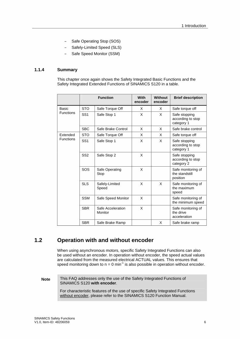
1.1.4 Summary
This chapter once again shows the Safety Integrated Basic Functions and the Safety Integrated Extended Functions of SINAMICS S120 in a table.
Function With encoder
Withoutencoder
Brief description
STO Safe Torque Off X X Safe torque off
SS1 Safe Stop 1 X X Safe stopping according to stop category 1
Basic Functions
SBC Safe Brake Control X X Safe brake control
STO Safe Torque Off X X Safe torque off
SS1 Safe Stop 1 X X Safe stopping according to stop category 1
SS2 Safe Stop 2 X Safe stopping according to stop category 2
SOS Safe Operating Stop
X Safe monitoring of the standstill position
SLS Safely-Limited Speed
X X Safe monitoring of the maximum speed
SSM Safe Speed Monitor X Safe monitoring of the minimum speed
SBR Safe Acceleration Monitor
X Safe monitoring of the drive acceleration
Extended Functions
SBR Safe Brake Ramp X Safe brake ramp
1.2 Operation with and without encoder
When using asynchronous motors, specific Safety Integrated Functions can also be used without an encoder. In operation without encoder, the speed actual values are calculated from the measured electrical ACTUAL values. This ensures that speed monitoring down to n = 0 min-1 is also possible in operation without encoder.
Note This FAQ addresses only the use of the Safety Integrated Functions of SINAMICS S120 with encoder.
For characteristic features of the use of specific Safety Integrated Functions without encoder, please refer to the SINAMICS S120 Function Manual.
1 Introduction
SINAMICS Safety Functions V1.0, Item-ID: 48206059 7
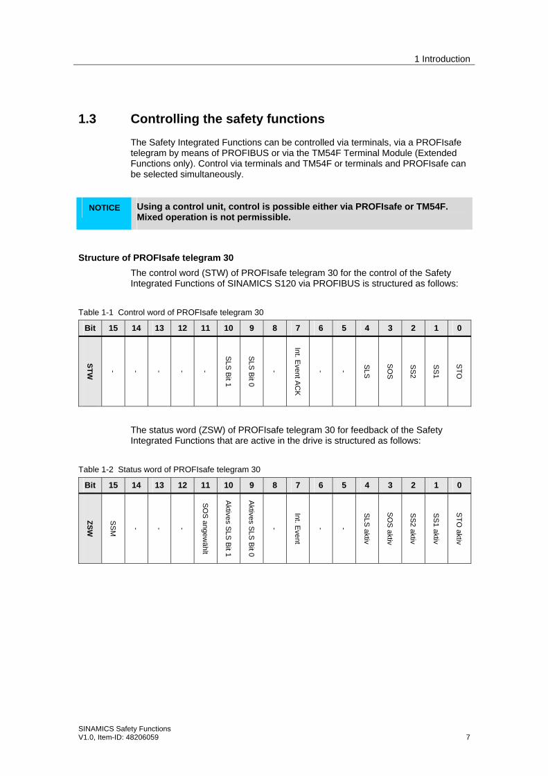
1.3 Controlling the safety functions
The Safety Integrated Functions can be controlled via terminals, via a PROFIsafe telegram by means of PROFIBUS or via the TM54F Terminal Module (Extended Functions only). Control via terminals and TM54F or terminals and PROFIsafe can be selected simultaneously.
NOTICE Using a control unit, control is possible either via PROFIsafe or TM54F. Mixed operation is not permissible.
Structure of PROFIsafe telegram 30
The control word (STW) of PROFIsafe telegram 30 for the control of the Safety Integrated Functions of SINAMICS S120 via PROFIBUS is structured as follows:
Table 1-1 Control word of PROFIsafe telegram 30
Bit 15 14 13 12 11 10 9 8 7 6 5 4 3 2 1 0
ST
W
- - - - -
SLS
Bit 1
SLS
Bit 0
-
Int. Event A
CK
- -
SLS
SO
S
SS
2
SS
1
ST
O
The status word (ZSW) of PROFIsafe telegram 30 for feedback of the Safety Integrated Functions that are active in the drive is structured as follows:
Table 1-2 Status word of PROFIsafe telegram 30
Bit 15 14 13 12 11 10 9 8 7 6 5 4 3 2 1 0
ZS
W
SS
M
- - -
SO
S angew
ählt
Aktives S
LS B
it 1
Aktives S
LS B
it 0
-
Int. Event
- -
SL
S a
ktiv
SO
S a
ktiv
SS
2 aktiv
SS
1 aktiv
ST
O aktiv
1 Introduction
SINAMICS Safety Functions V1.0, Item-ID: 48206059 8
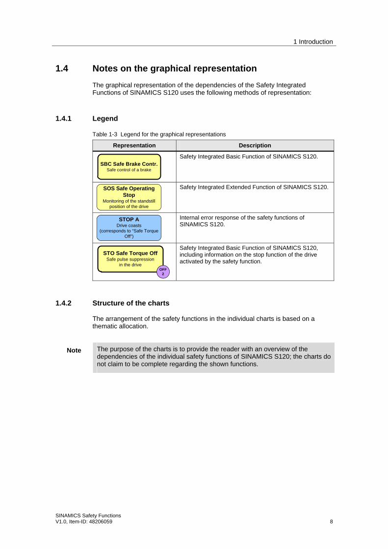
1.4 Notes on the graphical representation
The graphical representation of the dependencies of the Safety Integrated Functions of SINAMICS S120 uses the following methods of representation:
1.4.1 Legend
Table 1-3 Legend for the graphical representations
Representation Description
SBC Safe Brake Contr.Safe control of a brake
Safety Integrated Basic Function of SINAMICS S120.
SOS Safe Operating Stop
Monitoring of the standstill position of the drive
Safety Integrated Extended Function of SINAMICS S120.
STOP ADrive coasts
(corresponds to “Safe Torque Off”)
Internal error response of the safety functions of SINAMICS S120.
STO Safe Torque OffSafe pulse suppression
in the driveOFF
2
Safety Integrated Basic Function of SINAMICS S120, including information on the stop function of the drive activated by the safety function.
1.4.2 Structure of the charts
The arrangement of the safety functions in the individual charts is based on a thematic allocation.
Note The purpose of the charts is to provide the reader with an overview of the dependencies of the individual safety functions of SINAMICS S120; the charts do not claim to be complete regarding the shown functions.
2 Safety Integrated Basic Functions
SINAMICS Safety Functions V1.0, Item-ID: 48206059 9
2 Safety Integrated Basic Functions
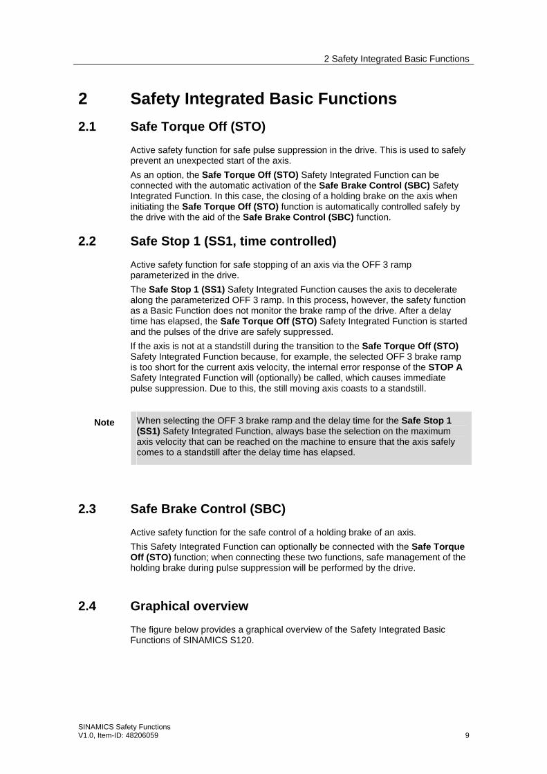
2.1 Safe Torque Off (STO)
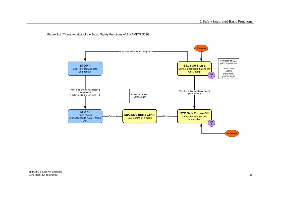
Active safety function for safe pulse suppression in the drive. This is used to safely prevent an unexpected start of the axis.
As an option, the Safe Torque Off (STO) Safety Integrated Function can be connected with the automatic activation of the Safe Brake Control (SBC) Safety Integrated Function. In this case, the closing of a holding brake on the axis when initiating the Safe Torque Off (STO) function is automatically controlled safely by the drive with the aid of the Safe Brake Control (SBC) function.
2.2 Safe Stop 1 (SS1, time controlled)
Active safety function for safe stopping of an axis via the OFF 3 ramp parameterized in the drive.
The Safe Stop 1 (SS1) Safety Integrated Function causes the axis to decelerate along the parameterized OFF 3 ramp. In this process, however, the safety function as a Basic Function does not monitor the brake ramp of the drive. After a delay time has elapsed, the Safe Torque Off (STO) Safety Integrated Function is started and the pulses of the drive are safely suppressed.
If the axis is not at a standstill during the transition to the Safe Torque Off (STO) Safety Integrated Function because, for example, the selected OFF 3 brake ramp is too short for the current axis velocity, the internal error response of the STOP A Safety Integrated Function will (optionally) be called, which causes immediate pulse suppression. Due to this, the still moving axis coasts to a standstill.
Note When selecting the OFF 3 brake ramp and the delay time for the Safe Stop 1 (SS1) Safety Integrated Function, always base the selection on the maximum axis velocity that can be reached on the machine to ensure that the axis safely comes to a standstill after the delay time has elapsed.
2.3 Safe Brake Control (SBC)
Active safety function for the safe control of a holding brake of an axis.
This Safety Integrated Function can optionally be connected with the Safe Torque Off (STO) function; when connecting these two functions, safe management of the holding brake during pulse suppression will be performed by the drive.
2.4 Graphical overview
The figure below provides a graphical overview of the Safety Integrated Basic Functions of SINAMICS S120.
2 Safety Integrated Basic Functions
SINAMICS Safety Functions V1.0, Item-ID: 48206059 10
Figure 2-1 Characteristics of the Basic Safety Functions of SINAMICS S120
STOP ADrive coasts
(corresponds to “Safe Torque Off”)
STO Safe Torque OffSafe pulse suppression
in the drive
SS1 Safe Stop 1Drive is decelerated along the
OFF3 ramp
SBC Safe Brake Contr.Safe control of a brake
STOP FError in crosswise data
comparison
After the delay time has elapsedp9652/p9852
Activation of SS1:p9652/p9852 > 0
OFF3 ramp:p1135
Delay time:p9652/p9852
Optional
Activation of SBC:p9602/p9802
Optional
After a delay time has elapsedp9658/p9858
Factory setting: Delay time = 0
OFF 3
OFF 2
Activation
Activation
Error in crosswise data comparison
3 Safety Integrated Extended Functions
SINAMICS Safety Functions V1.0, Item-ID: 48206059 11
3 Safety Integrated Extended Functions
Note The graphical representation of the Safety Integrated Functions is thematically structured; due to this, it is possible that individual Safety Integrated Functions are shown in several charts.
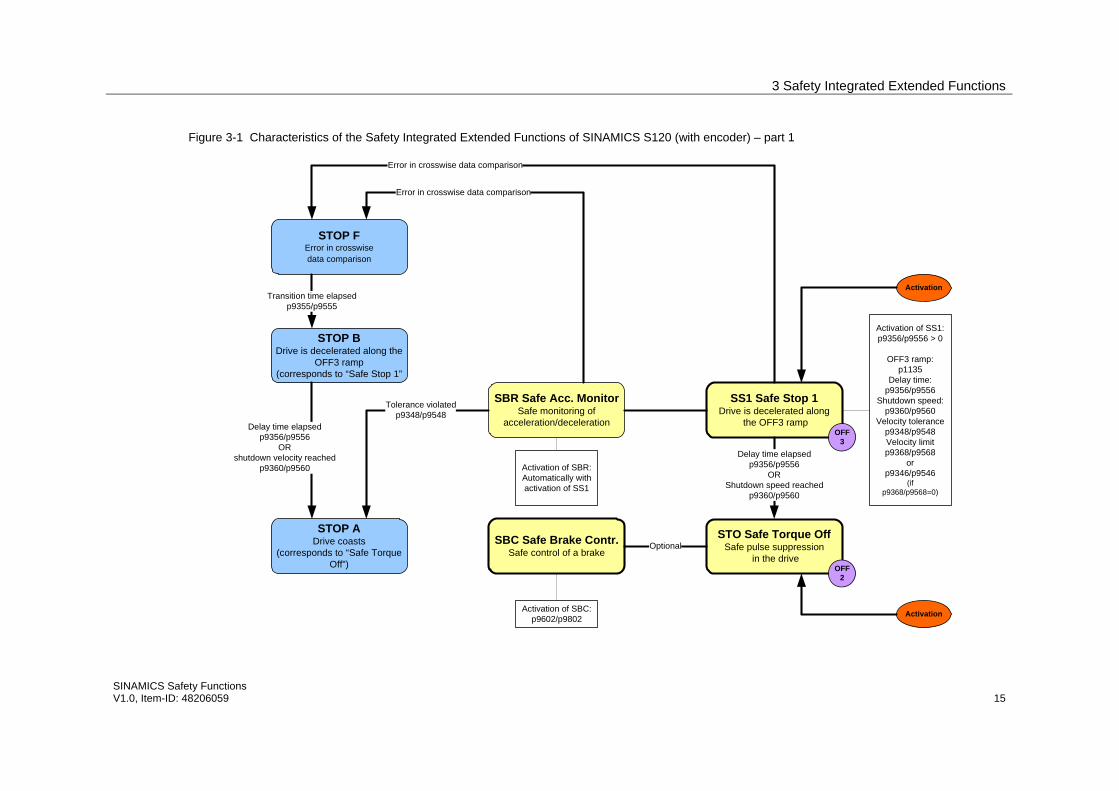
3.1 Safe Torque Off (STO)
Active safety function for safe pulse suppression in the drive. This is used to safely prevent an unexpected start of the axis.
As an option, the Safe Torque Off (STO) Safety Integrated Function can be connected with the automatic activation of the Safe Brake Control (SBC) Safety Integrated Basic Function. In this case, the closing of a holding brake on the axis when initiating the Safe Torque Off (STO) function is automatically controlled safely by the drive with the aid of the Safe Brake Control (SBC) function.
3.2 Safe Stop 1 (SS1, time and acceleration controlled)
Active safety function for safe stopping of an axis via the OFF 3 ramp parameterized in the drive.
The Safe Stop 1 (SS1) Safety Integrated Function causes the axis to decelerate along the parameterized OFF 3 ramp. In this process, the deceleration of the axis is monitored via the Safe Acceleration Monitor (SBR) Safety Integrated Function. After reaching the shutdown speed or after the delay time has elapsed, the Safe Torque Off (STO) Safety Integrated Function is started and the pulses of the drive are safely suppressed.
Note When selecting the OFF 3 brake ramp and the delay time for the Safe Stop 1 (SS1) Safety Integrated Function, always base the selection on the maximum axis velocity that can be reached on the machine to ensure that the axis safely comes to a standstill after the delay time has elapsed.
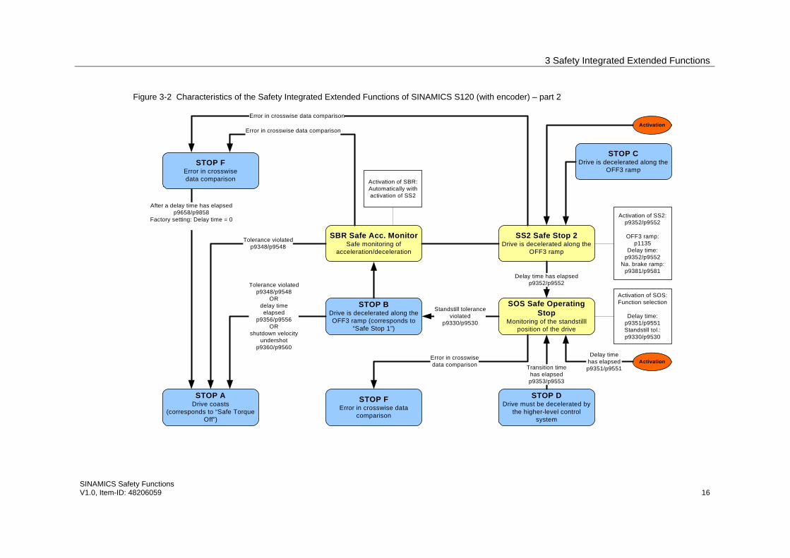
3.3 Safe Stop 2 (SS2)
Active safety function for safe braking of the motor with a subsequent transition to “Safe Operating Stop” (SOS).
The Safe Stop 2 (SS2) Safety Integrated Function causes the axis to decelerate along the parameterized OFF 3 ramp. In this process, the deceleration of the axis is monitored via the Safe Acceleration Monitor (SBR) Safety Integrated Function. After a delay time has elapsed, the Safe Operating Stop (SOS) Safety Integrated Function is started, which safely monitors the drive against unintentional movement. The actual drive, however, remains fully active and keeps the axis in closed-loop control mode.
3 Safety Integrated Extended Functions
SINAMICS Safety Functions V1.0, Item-ID: 48206059 12
Safety fault on Safe Acceleration Monitor/Safe Brake Ramp (SBR)
If the parameterized velocity tolerance is violated when monitoring the brake ramp using the Safe Acceleration Monitor (SBR) Safety Integrated Function, STOP A will be initiated and the drive will coast to a standstill without power supply.
Safety fault on Safe Operating Stop (SOS)
If the standstill tolerance is violated when monitoring the safe standstill of the axis using the Safe Operating Stop (SOS) Safety Integrated Function, STOP B will be initiated and the drive will be decelerated to a standstill via the OFF 3 ramp.
After the delay time has elapsed or if the shutdown velocity of the axis is undershot or the velocity tolerance for deceleration is overshot, STOP A will be initiated and the axis will coast to a standstill without power supply.
3.4 Safe Operating Stop (SOS)
Safe monitoring function to protect against unintentional movement. The drive is in closed-loop control mode and not disconnected from the power supply.
If the standstill tolerance is violated when monitoring the standstill of the axis, STOP B with subsequent STOP A will be initiated, decelerating the axis along the OFF 3 ramp and disconnecting it from the power supply.
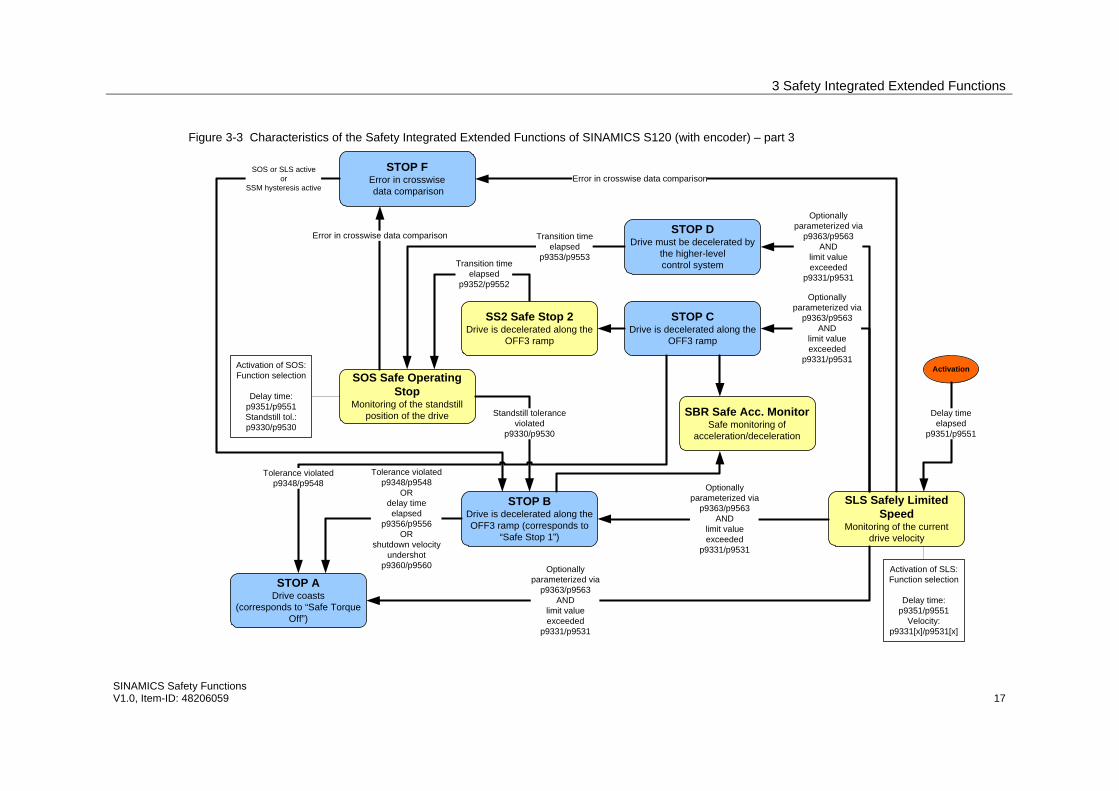
3.5 Safely-Limited Speed (SLS)
Safe monitoring function to protect against unintentionally high speeds of the drive.
When activating the Safely-Limited Speed (SLS) Safety Integrated Function, a delay time is started within which the axis velocity must be reduced by the higher-level control system below the value configured in the safety function.
Optional configuration of the response to a safety fault
The response to a safety fault of the Safely-Limited Speed (SLS) Safety Integrated Function, e.g. exceeding the configured axis velocity, can be optionally parameterized.
The following table serves as an example of the selection of the respective response to a safety fault.
Table 3-1 Response of Safely Limited Speed (SLS) to a safety fault
Response Comment
STOP D (= SOS)
The drive must be decelerated by the higher-level control system within the configured transition time (bit 3 “SOS active” is set in the status word of the PROFIsafe telegram). The standstill of the axis is then monitored via the Safe Operating Stop (SOS) Safety Integrated Function. The axis remains in closed-loop control mode. This setting is, for example, useful when axes move in a coordinated fashion (interpolation) if the coordination of the axes is not to be lost during the deceleration process (e.g., the trajectory is not to be left).
STOP C (= SS2)
The drive is decelerated via the configured OFF 3 ramp. If the velocity tolerance is violated before or after the deceleration process, the drive will go to STOP A, disconnecting the drive from the power supply
3 Safety Integrated Extended Functions
SINAMICS Safety Functions V1.0, Item-ID: 48206059 13
Response Comment
by immediate pulse suppression. The standstill of the axis is monitored via the Safe Operating Stop (SOS) Safety Integrated Function. The axis remains in closed-loop control mode. This setting is, for example, useful for single axes that can be decelerated using the OFF 3 drive function and, monitored using Safe Operating Stop (SOS), are then to remain in closed-loop control mode.
STOP B (= SS1)
The drive is decelerated via the configured OFF 3 ramp. If the velocity tolerance is violated before or after the deceleration process, the drive will go to STOP A, disconnecting the drive from the power supply by immediate pulse suppression. This setting is, for example, useful for single axes that can be decelerated using the OFF 3 drive function and are then not to remain in closed-loop control mode but can be disconnected from the power supply.
STOP A (= STO)
The drive is disconnected from power supply by immediate pulse suppression, which causes the axis to coast to a standstill. This setting is, for example, only useful for axes that can coast freely to a standstill or have an operating brake for mechanical stopping of the axis.
3.6 Safe Speed Monitor (SSM)
Safe monitoring function to monitor a specified speed limit with output of a safe output signal, without causing an influence of the drive.
This monitoring function will be automatically activated once a Safety Integrated Extended Function has been configured in SINAMICS S120.
3.7 Safe Acceleration Monitor (SBR)
Safe monitoring function to monitor incorrect acceleration of the drive with active Safe Stop 1 (SS1) and Safe Stop 2 (SS2) Safety Integrated Extended Function or STOP A and STOP B.
3.8 Safe Brake Ramp (SBR)
Safe monitoring function to monitor the brake ramp of the drive in operation without encoder.
This function is part of the Safe Stop 1 (SS1) and Safe Stop 2 (SS2) Safety Integrated Extended Function in operation without encoder.
Note The following graphical representations of the dependencies of the SINAMICS S120 safety functions do not address operation without encoder.
For characteristic features of the use of specific safety functions without encoder, please refer to the SINAMICS S120 Function Manual.
3 Safety Integrated Extended Functions
SINAMICS Safety Functions V1.0, Item-ID: 48206059 14
3.9 Graphical overview
The following four figures provide a graphical overview of the Safety Integrated Extended Functions of SINAMICS S120.
Safety Integrated Extended Functions – part 1
Safe Torque Off (STO) incl. Safe Brake Control (SBC)
Safe Stop 1 (SS1) incl. Safe Acceleration Monitor (SBR)
Safety Integrated Extended Functions – part 2
Safe Operating Stop (SOS)
Safe Stop 2 (SS2) incl. Safe Acceleration Monitor (SBR)
Safety Integrated Extended Functions – part 3
Safely Limited Speed (SLS)
Safe Operating Stop (SOS)
Safety Integrated Extended Functions – part 4
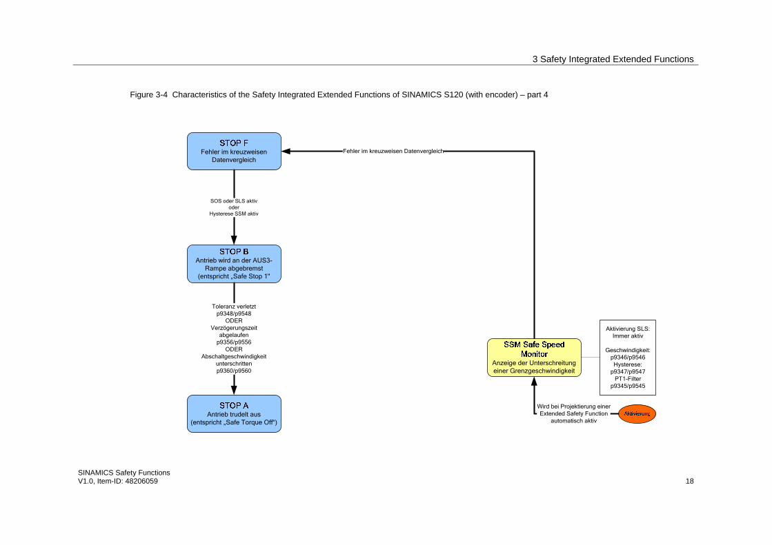
Safe Speed Monitor (SSM)
3 Safety Integrated Extended Functions
SINAMICS Safety Functions V1.0, Item-ID: 48206059 15
Figure 3-1 Characteristics of the Safety Integrated Extended Functions of SINAMICS S120 (with encoder) – part 1
STOP ADrive coasts
(corresponds to “Safe Torque Off”)
STOP BDrive is decelerated along the
OFF3 ramp(corresponds to “Safe Stop 1”
SS1 Safe Stop 1Drive is decelerated along
the OFF3 ramp
SBR Safe Acc. MonitorSafe monitoring of
acceleration/deceleration
STOP FError in crosswise data comparison
STO Safe Torque OffSafe pulse suppression
in the drive
SBC Safe Brake Contr.Safe control of a brake
Optional
Activation of SBC:p9602/p9802
Activation of SS1:p9356/p9556 > 0
OFF3 ramp:p1135
Delay time:p9356/p9556
Shutdown speed:p9360/p9560
Velocity tolerancep9348/p9548Velocity limitp9368/p9568
orp9346/p9546
(if p9368/p9568=0)
Delay time elapsed p9356/p9556
ORShutdown speed reached
p9360/p9560
OFF 3
OFF 2
Tolerance violatedp9348/p9548
Transition time elapsedp9355/p9555
Delay time elapsed p9356/p9556
ORshutdown velocity reached
p9360/p9560
Error in crosswise data comparison
Activation
Activation
Error in crosswise data comparison
Activation of SBR:Automatically with activation of SS1
3 Safety Integrated Extended Functions
SINAMICS Safety Functions V1.0, Item-ID: 48206059 16
Figure 3-2 Characteristics of the Safety Integrated Extended Functions of SINAMICS S120 (with encoder) – part 2
SS2 Safe Stop 2Drive is decelerated along the
OFF3 ramp
SOS Safe Operating Stop
Monitoring of the standstilll position of the drive
Delay time has elapsedp9352/p9552
Activation of SS2:p9352/p9552
OFF3 ramp:p1135
Delay time:p9352/p9552
Na. brake ramp:p9381/p9581
Activation of SOS:Function selection
Delay time:p9351/p9551Standstill tol.:p9330/p9530
SBR Safe Acc. MonitorSafe monitoring of
acceleration/deceleration
STOP ADrive coasts
(corresponds to “Safe Torque Off”)
STOP BDrive is decelerated along the OFF3 ramp (corresponds to
“Safe Stop 1”)
Tolerance violatedp9348/p9548
After a delay time has elapsedp9658/p9858
Factory setting: Delay time = 0
Error in crosswise data comparison
Standstill toleranceviolated
p9330/p9530
Tolerance violatedp9348/p9548
ORdelay timeelapsed
p9356/p9556OR
shutdown velocityundershot
p9360/p9560
STOP FError in crosswise data
comparison
Error in crosswise data comparison
ActivationDelay time
has elapsedp9351/p9551
Activation
STOP FError in crosswise data comparison
Error in crosswise data comparison
STOP CDrive is decelerated along the
OFF3 ramp
STOP DDrive must be decelerated by
the higher-level control system
Transition timehas elapsedp9353/p9553
Activation of SBR:Automatically with activation of SS2
3 Safety Integrated Extended Functions
SINAMICS Safety Functions V1.0, Item-ID: 48206059 17
Figure 3-3 Characteristics of the Safety Integrated Extended Functions of SINAMICS S120 (with encoder) – part 3
STOP CDrive is decelerated along the
OFF3 ramp
STOP DDrive must be decelerated by
the higher-level control system
SLS Safely Limited Speed
Monitoring of the current drive velocity
Activation of SLS:Function selection
Delay time:p9351/p9551
Velocity:p9331[x]/p9531[x]
Activation
Delay timeelapsed
p9351/p9551
STOP ADrive coasts
(corresponds to “Safe Torque Off”)
STOP BDrive is decelerated along the OFF3 ramp (corresponds to
“Safe Stop 1”)
STOP FError in crosswise data comparison
Error in crosswise data comparison
Optionallyparameterized via
p9363/p9563AND
limit value exceeded
p9331/p9531
Optionallyparameterized via
p9363/p9563AND
limit value exceeded
p9331/p9531
Optionallyparameterized via
p9363/p9563AND
limit valueexceeded
p9331/p9531
Optionallyparameterized via
p9363/p9563AND
limit value exceeded
p9331/p9531
Tolerance violatedp9348/p9548
ORdelay time elapsed
p9356/p9556OR
shutdown velocityundershot
p9360/p9560
Tolerance violatedp9348/p9548
SOS Safe Operating Stop
Monitoring of the standstill position of the drive
Activation of SOS:Function selection
Delay time:p9351/p9551Standstill tol.:p9330/p9530
Standstill toleranceviolated
p9330/p9530
Error in crosswise data comparison Transition timeelapsed
p9353/p9553Transition time
elapsedp9352/p9552
SOS or SLS activeor
SSM hysteresis active
SBR Safe Acc. MonitorSafe monitoring of
acceleration/deceleration
SS2 Safe Stop 2Drive is decelerated along the
OFF3 ramp
3 Safety Integrated Extended Functions
SINAMICS Safety Functions V1.0, Item-ID: 48206059 18
Figure 3-4 Characteristics of the Safety Integrated Extended Functions of SINAMICS S120 (with encoder) – part 4
Aktivierung SLS:Immer aktiv
Geschwindigkeit:p9346/p9546Hysterese:
p9347/p9547PT1-Filter
p9345/p9545
Wird bei Projektierung einerExtended Safety Function
automatisch aktivAntrieb trudelt aus
(entspricht „Safe Torque Off“)
Antrieb wird an der AUS3-Rampe abgebremst
(entspricht „Safe Stop 1"
Fehler im kreuzweisen Datenvergleich
Fehler im kreuzweisen Datenvergleich
Anzeige der Unterschreitung einer Grenzgeschwindigkeit
SOS oder SLS aktivoder
Hysterese SSM aktiv
Toleranz verletztp9348/p9548
ODERVerzögerungszeit
abgelaufenp9356/p9556
ODERAbschaltgeschwindigkeit
unterschrittenp9360/p9560

4 Additional Information
SINAMICS Safety Functions V1.0, Item-ID: 48206059 19
4 Additional Information
4.1 Designing the Safety Integrated Functions
4.1.1 Setting the delay times
The settings of the delay times must be based on the following aspects:
Consideration of mechanical conditions such as maximum axis velocity, involved centrifugal masses, etc.
Consideration of involved standards, which, for instance, include required stopping times.
Consideration of risk analyses that may have to be performed.
Note If, during the deceleration process of an axis with active Safe Acceleration Monitor (SBR) monitoring function, the current velocity falls below the zero line (“undershoot”), the return to the zero line will be assessed as an acceleration in the safety function and the Safety Integrated Function will trigger an error.
Therefore, set the tolerance of the Safety Integrated Function accordingly to ensure that the drop in velocity below the zero line can be tolerated by the function. In addition, optimize the axis settings so that the drop of the current velocity below the zero line (“undershoot”) can be kept as small as possible.
4.1.2 Setting the brake ramps
Base the settings of the brake ramps for the individual axes on the respective maximum process speed of the machine. This ensures that, using the set brake ramp, the axis comes to a standstill within a defined period of time.
4.1.3 Selecting the appropriate Safety Integrated Function
If possible, select the appropriate Safety Integrated Functions for the relevant axes of a machine.
Please note the following:
Single axes can be directly influenced via active safety functions.
Axes within a group of axes (e.g., multiple axis interpolation) should only be influenced by the control system while being monitored, for example, with the aid of a safe monitoring function. This ensures that contour deviation during the deceleration process or damage to the machine can be avoided. This note should be considered particularly for the optional selection of the internal error response of the STOP A/B/C/D Safety Integrated Extended Functions.
4 Additional Information
SINAMICS Safety Functions V1.0, Item-ID: 48206059 20
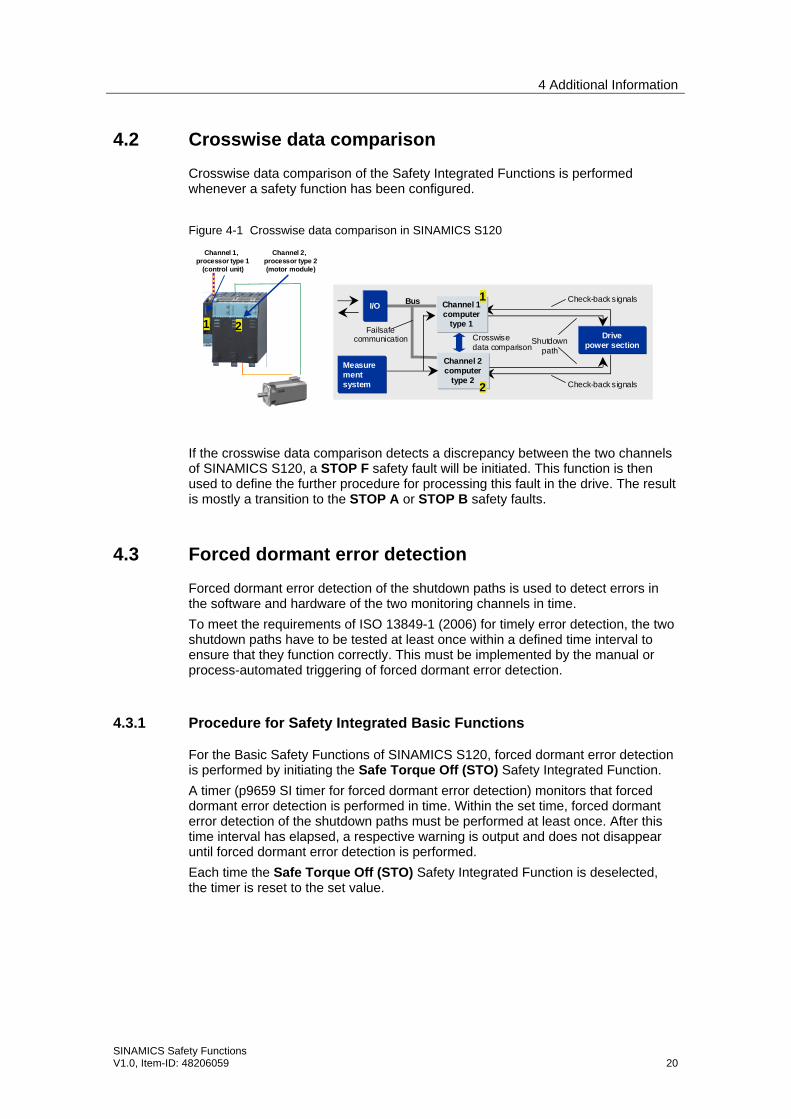
4.2 Crosswise data comparison
Crosswise data comparison of the Safety Integrated Functions is performed whenever a safety function has been configured.
Figure 4-1 Crosswise data comparison in SINAMICS S120
21
Channel 2, processor type 2(motor module)
Channel 1, processor type 1
(control unit)
Crosswisedata comparison
Check-back signals
Check-back signalsBusI/O
Measurementsystem
Shutdown path
Drive power section
Channel 1 computer
type 1
Channel 2computer
type 2
Failsafecommunication
1
2
If the crosswise data comparison detects a discrepancy between the two channels of SINAMICS S120, a STOP F safety fault will be initiated. This function is then used to define the further procedure for processing this fault in the drive. The result is mostly a transition to the STOP A or STOP B safety faults.
4.3 Forced dormant error detection
Forced dormant error detection of the shutdown paths is used to detect errors in the software and hardware of the two monitoring channels in time.
To meet the requirements of ISO 13849-1 (2006) for timely error detection, the two shutdown paths have to be tested at least once within a defined time interval to ensure that they function correctly. This must be implemented by the manual or process-automated triggering of forced dormant error detection.
4.3.1 Procedure for Safety Integrated Basic Functions
For the Basic Safety Functions of SINAMICS S120, forced dormant error detection is performed by initiating the Safe Torque Off (STO) Safety Integrated Function.
A timer (p9659 SI timer for forced dormant error detection) monitors that forced dormant error detection is performed in time. Within the set time, forced dormant error detection of the shutdown paths must be performed at least once. After this time interval has elapsed, a respective warning is output and does not disappear until forced dormant error detection is performed.
Each time the Safe Torque Off (STO) Safety Integrated Function is deselected, the timer is reset to the set value.
4 Additional Information
SINAMICS Safety Functions V1.0, Item-ID: 48206059 21
4.3.2 Procedure for Safety Integrated Extended Functions
For the Safety Integrated Extended Functions of SINAMICS S120, forced dormant error detection is performed by initiating a test stop. This test stop tests the two shutdown paths of the Safe Torque Off (STO) Safety Integrated Function. In this process, the drive behavior corresponds to a selection of the Safe Torque Off (STO) Safety Integrated Function with automatic deselection of the function after a configurable period of time.
A timer (p9559 SI Motion forced dormant error detection timer (control unit)) monitors that forced dormant error detection is performed in time. Within the set time, forced dormant error detection of the shutdown paths must be performed at least once. After this time interval has elapsed, a respective warning is output and a BICO output (r9723.0 CO/BO: SI Motion drive-integrated diagnostics signals) is set. The warning does not disappear until forced dormant error detection is performed.
Forced dormant error detection is triggered via a BICO input (p9705 BI: SI Motion test stop signal source) and acknowledged by canceling this input. In this process, forced dormant error detection does not require PowerOn of the SINAMICS S120 drive system.
Note The test stop of the safety functions initiates the Safe Torque Off (STO) Safety Integrated Function. Safe Torque Off (STO) must not have been selected before selecting the test stop.
When using blocksize Power Modules, the test stop must be initiated at a closed-loop controlled standstill of the axis (speed setpoint = 0, motor supplied with power).
Note It is recommended that the test stop be performed directly after the startup of the drive and before enabling the axes.