technology consumer industrial
TRANSCRIPT
Electronic TrainingEquipment
Technology
Consumer
Industrial
www.promaxelectronics.com

For two decades now, PROMAX ELECTRONICA has beendesigning education related instruments. Over the last fewyears, we have assigned a laboratory specifically for designinga range of latest-generation educational instruments to helptrain future professionals in the emerging technologies field(fibre optics, digital television, MPEG-2…) and other evolving technologies (telephony, digital electronics, consumerelectronics…).
Below we present a brief list of our Educational range products.
ELECTRONIC TRAINING EQUIPMENT
2
3
ELECTRONIC TRAINING EQUIPMENT
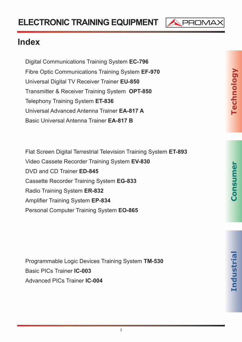
Index
Digital Communications Training System EC-796
Fibre Optic Communications Training System EF-970
Universal Digital TV Receiver Trainer EU-850
Transmitter & Receiver Training System OPT-850
Telephony Training System ET-836
Universal Advanced Antenna Trainer EA-817 A
Basic Universal Antenna Trainer EA-817 B
Flat Screen Digital Terrestrial Television Training System ET-893
Video Cassete Recorder Training System EV-830
DVD and CD Trainer ED-845
Cassette Recorder Training System EG-833
Radio Training System ER-832
Amplifier Training System EP-834
Personal Computer Training System EO-865
Programmable Logic Devices Training System TM-530
Basic PICs Trainer IC-003
Advanced PICs Trainer IC-004
Tech
no
log
yC
on
sum
er
Ind
ust
rial
4
EC-796
Digital Communications Training System
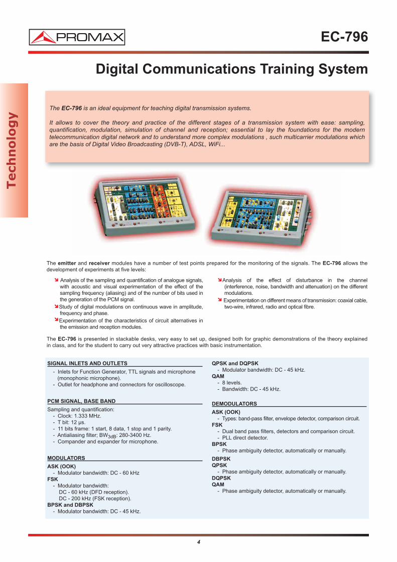
The EC-796 is an ideal equipment for teaching digital transmission systems.
It allows to cover the theory and practice of the different stages of a transmission system with ease: sampling, quantification, modulation, simulation of channel and reception; essential to lay the foundations for the modern telecommunication digital network and to understand more complex modulations , such multicarrier modulations whichare the basis of Digital Video Broadcasting (DVB-T), ADSL, WiFi...
The emitter and receiver modules have a number of test points prepared for the monitoring of the signals. The EC-796 allows the development of experiments at five levels:
The EC-796 is presented in stackable desks, very easy to set up, designed both for graphic demonstrations of the theory explained in class, and for the student to carry out very attractive practices with basic instrumentation.
Analysis of the sampling and quantification of analogue signals, with acoustic and visual experimentation of the effect of the sampling frequency (aliasing) and of the number of bits used in the generation of the PCM signal.Study of digital modulations on continuous wave in amplitude, frequency and phase.Experimentation of the characteristics of circuit alternatives in the emission and reception modules.
Analysis of the effect of disturbance in the channel (interference, noise, bandwidth and attenuation) on the different modulations.Experimentation on different means of transmission: coaxial cable,two-wire, infrared, radio and optical fibre.
SIGNAL INLETS AND OUTLETS
- Inlets for Function Generator, TTL signals and microphone(monophonic microphone).
- Outlet for headphone and connectors for oscilloscope.
PCM SIGNAL, BASE BAND
Sampling and quantification:- Clock: 1.333 MHz.- T bit: 12 µs.- 11 bits frame: 1 start, 8 data, 1 stop and 1 parity.- Antialiasing filter; BW3dB: 280-3400 Hz.- Compander and expander for microphone.
MODULATORS
ASK (OOK)
- Modulator bandwidth: DC - 60 kHzFSK
- Modulator bandwidth:DC - 60 kHz (DFD reception).DC - 200 kHz (FSK reception).
BPSK and DBPSK
- Modulator bandwidth: DC - 45 kHz.
QPSK and DQPSK
- Modulator bandwidth: DC - 45 kHz.QAM
- 8 levels.- Bandwidth: DC - 45 kHz.
DEMODULATORS
ASK (OOK)
- Types: band-pass filter, envelope detector, comparison circuit.FSK
- Dual band pass filters, detectors and comparison circuit.- PLL direct detector.
BPSK
- Phase ambiguity detector, automatically or manually.
DBPSK
QPSK
- Phase ambiguity detector, automatically or manually.DQPSK
QAM
- Phase ambiguity detector, automatically or manually.
Tech
no
log
y

5
EC-796
Digital Communications Training System
EMITTER CHARACTERISTICS
Twin Cable Emitter:
Output level (measured at connector):- Receiver not connected: 0 to ±4 V (according to modulation).- Receiver connected: 0 to ±3 V (according to modulation).
Connector: banana female adapter.
Coaxial Cable Emitter:
Output level (measured at connector):- Receiver not connected: 0 to ±4 V (according to modulation).- Receiver connected: 0 to ±3 V (according to modulation).
Connector: BNC female adapter.
Fibre Optic Emitter:
- Emission by LED.- Emission wave-length: 850 nm (red).- Connector: FSMA.
Infrared Emitter:
- Emission by LED.- Emission wave-length: 950 nm.
27 MHz Emitter:
- Output level at 50 Ω: 10 dBm.- Antenna: Monopole. 5 mm cable and 150 cm length.- Connector: BNC female.- Carrier frequency: 27 MHz (crystal).- Modulation on AM: Modulation index of 10 to 40%, according
to selected modulator signal.
RECEIVER CHARACTERISTICS
Twin-Line Cable Receiver:
- Type: Direct.- Connector: Banana adapter.
Coaxial Cable Receiver:
- Type: Direct.- Connector: BNC adapter.
Fibre Optic Receiver:
- Type: Photo-diode (PIN).- Reception band: 400 - 1100 nm (for 90% efficiency).- FSMA connector.
Infrared Receiver:
- Type: Photo-diode (PIN).- Reception band: 800 - 1000 nm (for 50% efficiency).
27 MHz Receiver:
- Type: Envelope detector.- Reception band: 27 MHz.- Antenna: Monopole. 5 mm cable, 150 cm length.- Connector: BNC female adapter.
ACCESSORIES AND DOCUMENTATION INCLUDED
- Antenna cables for radio transmission/reception.- Optical fibre PMMA with FSMA connectors.- Two wire and coaxial cables.- Headphone and dynamic microphone.- User’s Manual.- Theory Manual.- Instruction manual and technical data.
Recommended equipment:
Digital Oscilloscopes Series OD-4xx, OD-57x, OD-59x
Signal generators GF-230, GF-232, GF-941
Tech
no
log
y

6
EF-970-E
Fibre Optic Communications Training System
The EF-970E trainer is an innovative system designed for training, demonstration and experimentation with the Fibre Optics communication systems, the phenomenon related to light and the principles of transmission through OpticalFibres; as well as the latest tendencies like LASER and WDM (wavelength multiplexing). The equipment consists of:
- Emitter module, two independent channels with photo-emitters and LASER.- Receptor module with optical power measurements.- Accessories.- A set of Optic Fibres.- Documentation.
EMITTER KIT, CONSISTING OF TWO INDEPENDENT CHANNELS WITH LED AND LASER-PHOTOEMITTERS
TRANSMITTER MODULE RECEIVER MODULE
8 INPUTS
The instrument possesses eight selectionable inputs. The input signal may be selected, either channel 1 (CH 1) or channel 2 (CH 2), the same input may also be used for both channels.
LF generator: sinusoidal, triangular or square (internal) signal.
DC analogue input (75 Ω) (external).
AC analogue input (75 Ω) (external).
Microphone (monophonic) (external).
Digital input (External).
Inverted digital input (External).
Digital input permanently on "1" (internal).
Digital switch "1" / "0", using the TL1 key (internal).
CHANNEL 1 AND 2
The transmitter has 2 independent channels (1 and 2), which allowto transmit from any optic input, monitoring the amplification leveland the polarization.
LF GENERATOR (SQUARE, TRIANGULAR, SINUSOIDAL)
The BF generator possesses four control buttons to select the waveform (square, triangular or sinusoidal) and the frequency.
Tech
no
log
y

7
EF-970-E
Fibre Optic Communications Training System
OPTICAL OUTPUTS
The emitter kit has six cyclically selectable photoemitters. Two photoemitters may be activated at the same time for the WDM application (*). The photoemitters have a protection circuit to limit optical power.
MILLIAMMETER
The emitter kit consists of a digital milliammeter showing the polarisation current flowing through the chosen photoemitter. The channel to bemeasured is selected with the"mA METER CH1/CH2" button.
LASER FEEDBACK
The nature of the LASER means that its optical power may be influenced by external factors such as temperature, ageing, etc.
The feedback circuit is able to maintain a stable and unalterable optical power no matter what the external conditions are.
The system can operate with the feedback circuit ON or OFF so totest its efficiency and the problems caused by its disconnectionand/or malfunction.
RECEIVER KIT WITH OPTICAL POWER METER
RECEIVER
The receiver kit principally consists of two independent blocks (except for the input circuits: photodetectors and switches), one for the signal and the other for measuring.
The signal block contains two channels, also independent, one forreceiving analogue signals and the other for digital signals.
The measuring block contains the power meter, enabling operationin four different modes: analogue, digital, 1 kHz and DC.
OPTICAL INPUTS
The receiver has four incorporated photodetectors and an external photodetector (optional) that connects to the "EXT. SENSOR" input by a coaxial cable (optional).
DIGITAL CHANNEL SIGNAL BLOCK
The signal entering the digital channel follows a series of filteringand amplification processes for subsequent comparison with a reference level.
The amplitude of the channel output may be selected as either TTLlevel or RS-232 level.
OPTICAL POWER METER
This block performs the absolute or relative measurement of the received optical power. The optical meter possesses four measuringmodes, selected by the user.
ANALOG (monitoring mode).DIGITAL (monitoring mode).1 kHz (precision mode, for measuring the 1 kHz component).DC (precision mode).
The resolution of the power meter in the monitoring modes is 0.1 dB, and 0.01 dB in the precision modes.
ANALOGUE CHANNEL SIGNAL BLOCK
The resolution of the power meter in the monitoring modes is 0.1 dB, and 0.01 dB in the precision modes.
The signal block possesses a switch to select the type of coupling,DC or AC, applied to the first amplifier input and to the analoguechannel output section.
The audio section consists of an independently-adjustable low-passfor regulating the level of the signal applied to the internal speakeror headphones.
Tech
no
log
y
(*) Option OP-970-01 required

OPTICAL FIBRE
ARM
VARIABLE OPTICAL
ATTENUATORVARIABLE WDM
DEVICE
8
EF-970
Fibre Optic Communications Training System
INCLUDED ACCESSORIES
Both EF-970-E and EF-970 include the following accessories:
3 ST adapters for the photodetectors.Cleaning elements for optical components.3 1-m pieces of optical fibre.1 1-m piece of optical fibre without protective covering.1 50-m optical fibre.2 ST-ST adapters.1 magnifying lens.1 microphone.1 headphones.
The EF-970 is a simplified version of the EF-970-E, including five photo-emitters and two photo-detectors. The rest of features are the sameas those of the EF-970-E. If desired, the EF-970 can be upgraded to the EF-970-E with the OP-970-EU option.
OP-970-01: EXERCISES KIT
- 1 2-m piece of optical fibre.- 1 2-m piece of optical fibre without protective covering.- 1 set of modal filters (cylindrical hoops with various radiuses).- 2 clips for modal filters.- 1 set of plaques for generating high-density microcurves.- 1 set of plaques for generating low-density microcurves.- 1 optical fibre arm.- 2 fixed WDM devices.- 1 variable WDM device.- 1 white light source (powered by two LR03 1.5 V alkaline
batteries, not supplied).- 1 set of neutral optical filters.- 1 universal bracket (# 1).
- 1 universal bracket (# 2).- 1 variable attenuator.- 1 ST adapter for 650 nm filter photo-detectors.- 1 ST adapter for 850 nm filter photo-detectors.- 1 shutter (diaphragm).- 1 reflection sensor.- 1 reflecting lamina.- 1 U-sensor.- 1 liquid container.- 1 external photo-detector (1 mm Si PIN).- 1 measurement adapter (for external photo-detector).- 1 shielded connector cable for external photo-detector.- 1 screwdriver
OP-970-02: CONNECTION KIT
- 1 tool for removing the protective covering from optical fibre.
- 1 ST crimping tool.
- 1 polishing disk.
- 1 set of abrasive lamina.
- 1 elastic polishing pad.
- 1 rigid pad.
- 1 liquid container.
- 1 10- m optical fibre cable.
- 10 ST connectors.
OP-970-03: MICROSCOPE
- 1 Universal Microscope (ST, FC, SC) x 100.
OP-970-EU: EXTENSION KIT FOR BASIC FIBRE OPTICS
COMMUNICATIONS TRAINING SYSTEM (factory assembly)
Upgrades the basic Fibre Optics Trainer (EF-970) to the samecharacteristics as the EF-970-E.
- Photo-emitter 1300 nm LED.
- 1 mm InGaAs PIN photo-detector.
- 0.1 mm Ge APD (variable internal gain photo-detector).
Tech
no
log
y
EF-970 BASIC FIBRE OPTIC COMMUNICATIONS TRAINING SYSTEM
OPTIONS

EF-970
Fibre Optic Communications Training System
Tech
no
log
y
EMITTER MODULE
The emitter kit for the simultaneous transmission of two independent channels of up to 10 MHz, consists of the followingblocks:
Inputs- Analogue (separate DC and AC).- Functions generator (internal).- Microphone.- Digital (with possibility of inversion).
Emitter stage- Channel 1.- Channel 2, with actionable laser feedback.
AmperimeterFor adjusting photoemitter polarisation current
Photoemitters526, 590, 660, 850, 1300 nm LED **. 650 nm Laser.
RECEIVER MODULE
Photo-detectors- 1 mm Si PIN.- 1mm InGaAs PIN **.- 0.1 mm Ge APD (variable internal gain photodetector) **.- 2.5 mm Si PIN.
Precision measurements channels- 1 kHz, to prevent influence from external optical sources.- Very low DC noise, for very precise measurements.
Receptor stages (with variable inverse polarisation)- Analogue channel.- Digital channel.
Optical power meter (dBm and mW), absolute/relative measurem.Outputs
- Analogue (high or low impedance).- Digital (TTL or RS-232).- Speaker (internal) and headphones.
Fault simulator
CD-ROM SUPPLIED DOCUMENTATION
- User’s Manual.- Training Manual.- Teacher’s Manual.
PARTIAL LIST OF EXERCISES
EF-970
- Measuring optical power (suggested EF-970-E).- Measuring the attenuation of an optical fibre. Insertion losses
method (suggested EF-970-E).- Measuring the attenuation of an optical fibre.- Spectral dependence of the attenuation of an optical fibre.- Influence of ambient light.- Connecting optical fibre using ST-ST adapters.
Measuring repeatability.- Measuring the P/I characteristics of photoemitters.- Measuring the optical stability of photo-emitters.- Inverse voltage in photo-detectors.
- Measuring the V/I characteristics of photo-emitters.- Frequency characteristics of photo-emitter modulation.- Spectral dependence of photo-detectors (suggested EF-970-E).- Bandwidth of photo-detectors.- Transmission of analogue signals.- Transmission of audio signals.- Transmission of video signals.- Transmission of digital signals.- RS-232 transmission using optical fibres.
EF-970-E- Optical power measurement.- Measuring the attenuation of an optical fibre. Insertion losses method.- Measuring the attenuation of an optical fibre.- Spectral dependence of the attenuation of an optical fibre.- Influence of ambient light.- Connecting optical fibre using ST-ST adapters.
Measuring repeatability.- Measuring the P/I characteristics of photo-emitters.- Measuring the optical stability of photo-emitters.- Measuring the V/I characteristics of photo-emitters.- Frequency characteristics of photo-emitter modulation.- Spectral dependence of photo-detectors.- Inverse voltage in photo-detectors.- Bandwidth of photo-detectors.- Transmission of analogue signals.- Transmission of audio signals.- Transmission of video signals.- Transmission of digital signals.- RS-232 transmission by optical fibres.
OP-970-01 EXERCISES KIT
- Sensitivity of optical fibre to curvature (Macrocurves).- Sensitivity of optical fibre to microcurvature.- Radiation characteristics of optical fibre. Measuring numeric aperture.- Measuring sliding in optical fibre connections.- Characteristics of a fixed WDM device.- Characteristics of a variable WDM device.- Measurements with neutral optical fibres.- Measuring insertion loss by the variable optical attenuator.- WDM: multiplexation and demultiplexation.- WDM system.- WDM transmission.- Transmission sensor.- Reflection sensor.- Liquid level sensor.- Spectral dependence insertion loss by the variable optical
attenuator (EF-970-E needed).- Comparing noise characteristics between PIN and APD
photodetectors (EF-970-E needed).
OP-970-02 CONNECTION KIT
- Connections with the optical fibre connector tool kit EF-970or EF-970-E.
OP-970-03 MICROSCOPE
- Recommended for use with OP-970-02.
Recommended equipment:
Digital Oscilloscopes Series OD-4xx / OD-57x, OD-59x
TV signal generators GV-198, GV-698+, GV-798+
Optical power meter PROLITE-23
Optical spectrum analyser PROLITE-60
(**) This item is not supplied with EF-970 model
9
10
Trade Mark of the DVB Digital Video Broadcasting Project (4029)
EU-850
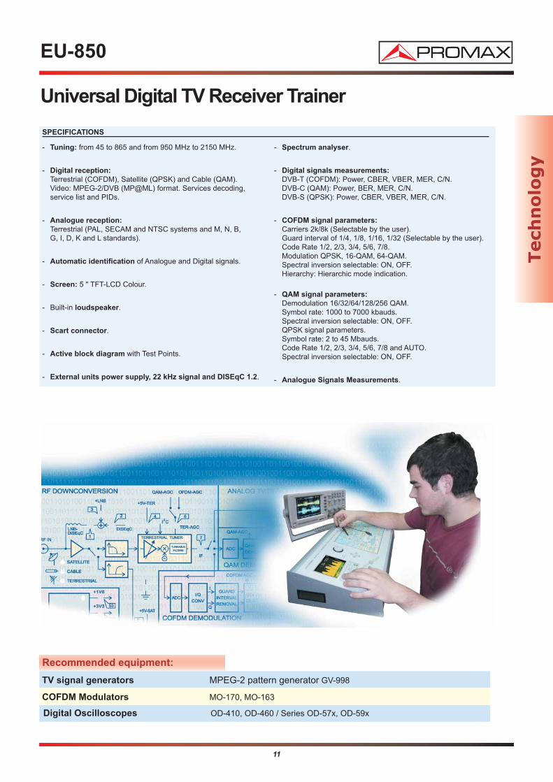
Universal Digital TV Receiver Trainer
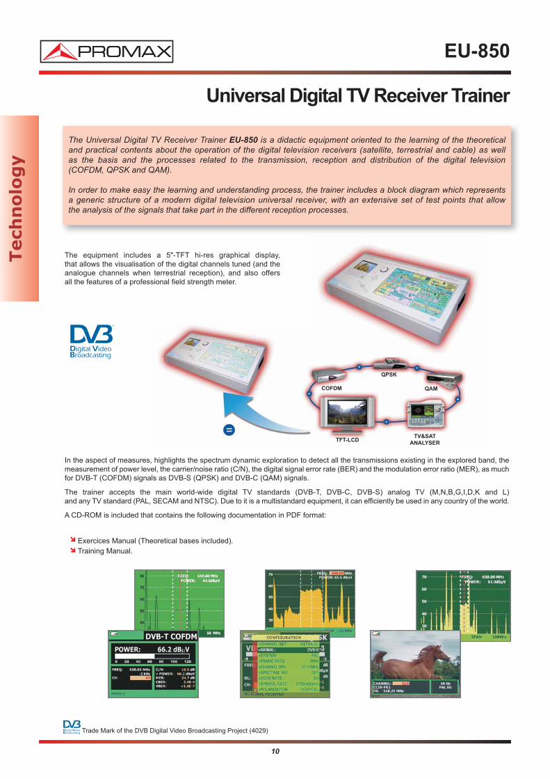
The Universal Digital TV Receiver Trainer EU-850 is a didactic equipment oriented to the learning of the theoretical and practical contents about the operation of the digital television receivers (satellite, terrestrial and cable) as well as the basis and the processes related to the transmission, reception and distribution of the digital television (COFDM, QPSK and QAM).
In order to make easy the learning and understanding process, the trainer includes a block diagram which represents a generic structure of a modern digital television universal receiver, with an extensive set of test points that allow the analysis of the signals that take part in the different reception processes.
The equipment includes a 5"-TFT hi-res graphical display, that allows the visualisation of the digital channels tuned (and theanalogue channels when terrestrial reception), and also offers all the features of a professional field strength meter.
In the aspect of measures, highlights the spectrum dynamic exploration to detect all the transmissions existing in the explored band, themeasurement of power level, the carrier/noise ratio (C/N), the digital signal error rate (BER) and the modulation error ratio (MER), as muchfor DVB-T (COFDM) signals as DVB-S (QPSK) and DVB-C (QAM) signals.
The trainer accepts the main world-wide digital TV standards (DVB-T, DVB-C, DVB-S) analog TV (M,N,B,G,I,D,K and L) and any TV standard (PAL, SECAM and NTSC). Due to it is a multistandard equipment, it can efficiently be used in any country of the world.
A CD-ROM is included that contains the following documentation in PDF format:
Exercices Manual (Theoretical bases included).Training Manual.
COFDM
QPSK
QAM
TFT-LCDTV&SAT
ANALYSER
Tech
no
log
y
11
EU-850
Universal Digital TV Receiver Trainer
- Tuning: from 45 to 865 and from 950 MHz to 2150 MHz.
- Digital reception:
Terrestrial (COFDM), Satellite (QPSK) and Cable (QAM).Video: MPEG-2/DVB (MP@ML) format. Services decoding,service list and PIDs.
- Analogue reception:
Terrestrial (PAL, SECAM and NTSC systems and M, N, B,G, I, D, K and L standards).
- Automatic identification of Analogue and Digital signals.
- Screen: 5 " TFT-LCD Colour.
- Built-in loudspeaker.
- Scart connector.
- Active block diagram with Test Points.
- External units power supply, 22 kHz signal and DISEqC 1.2.
- Spectrum analyser.
- Digital signals measurements:
DVB-T (COFDM): Power, CBER, VBER, MER, C/N.DVB-C (QAM): Power, BER, MER, C/N.DVB-S (QPSK): Power, CBER, VBER, MER, C/N.
- COFDM signal parameters:
Carriers 2k/8k (Selectable by the user).Guard interval of 1/4, 1/8, 1/16, 1/32 (Selectable by the user).Code Rate 1/2, 2/3, 3/4, 5/6, 7/8.Modulation QPSK, 16-QAM, 64-QAM.Spectral inversion selectable: ON, OFF.Hierarchy: Hierarchic mode indication.
- QAM signal parameters:
Demodulation 16/32/64/128/256 QAM.Symbol rate: 1000 to 7000 kbauds.Spectral inversion selectable: ON, OFF.QPSK signal parameters.Symbol rate: 2 to 45 Mbauds.Code Rate 1/2, 2/3, 3/4, 5/6, 7/8 and AUTO.Spectral inversion selectable: ON, OFF.
- Analogue Signals Measurements.
SPECIFICATIONS
Recommended equipment:
TV signal generators MPEG-2 pattern generator GV-998
COFDM Modulators MO-170, MO-163
Digital Oscilloscopes OD-410, OD-460 / Series OD-57x, OD-59x
Tech
no
log
y
12
OPT-850-A
DVB-T Transmitter-Receiver System
Thanks to the possibility of DVB-T signals broadcasting
through an antenna it is possible to simulate a real broadcast transmission. Moreover, using an additional antenna it makes possible the analysis of the DVB-T signal including every parameterinvolved, in such way that the student is able to understand the pros and cons of the different configurations.
By means of the use of OPT-870-A option the student will experience every concept related to DVB-T:
Number of carriers (2K or 8K).Constellation (QPSK, 16-QAM, 64-QAM).Guard interval.Code rate.Hierarchical Transmission.Bitrate.Bandwidth.Spectral inversion.Transmitted power.Etc.
The chance to change the parameters of the DVB-T makes possible for the student to experiment on the results of them on the transport stream.
The transmodulator can use an external transport stream or generate it internally. The external transport stream will be generated from the DVB-S input (the transmodulator will use its built in DVB-S receiver) o directly from its serial input (ASI); in both cases the student can adjust the transport stream bitrate to adapt it to the input speed required.
OPT-850-A consists of:
MO-163 transmodulator.2 high performance UHF Yagi antennas.Coaxial cable.Connectors.Practice manual (with theory).Instructions manual.
DVB-TMO-163
TransmodulatorEU-850Trainer
TERRESTRIAL
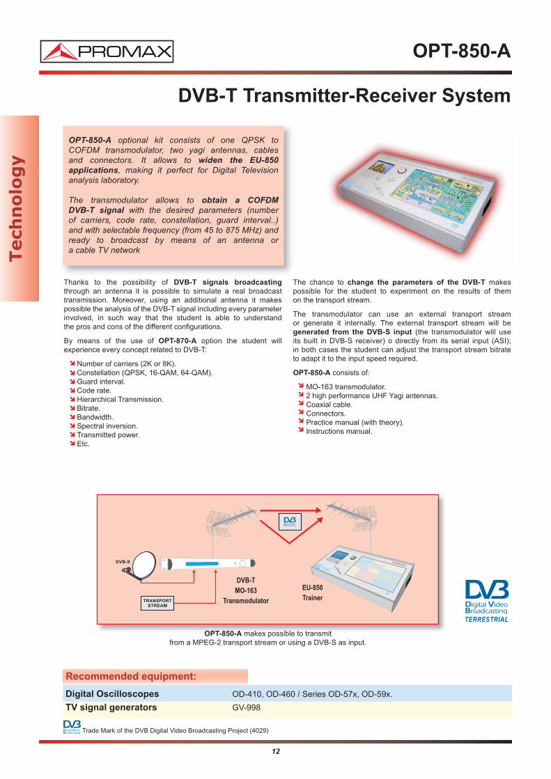
OPT-850-A makes possible to transmit from a MPEG-2 transport stream or using a DVB-S as input.
OPT-850-A optional kit consists of one QPSK to COFDM transmodulator, two yagi antennas, cables and connectors. It allows to widen the EU-850 applications, making it perfect for Digital Television analysis laboratory.
The transmodulator allows to obtain a COFDM DVB-T signal with the desired parameters (number of carriers, code rate, constellation, guard interval..) and with selectable frequency (from 45 to 875 MHz) andready to broadcast by means of an antenna or a cable TV network
Recommended equipment:
Digital Oscilloscopes OD-410, OD-460 / Series OD-57x, OD-59x.
TV signal generators GV-998
Trade Mark of the DVB Digital Video Broadcasting Project (4029)
Tech
no
log
y
13
OPT-850-A
Transmitter-Receiver DVB-T System
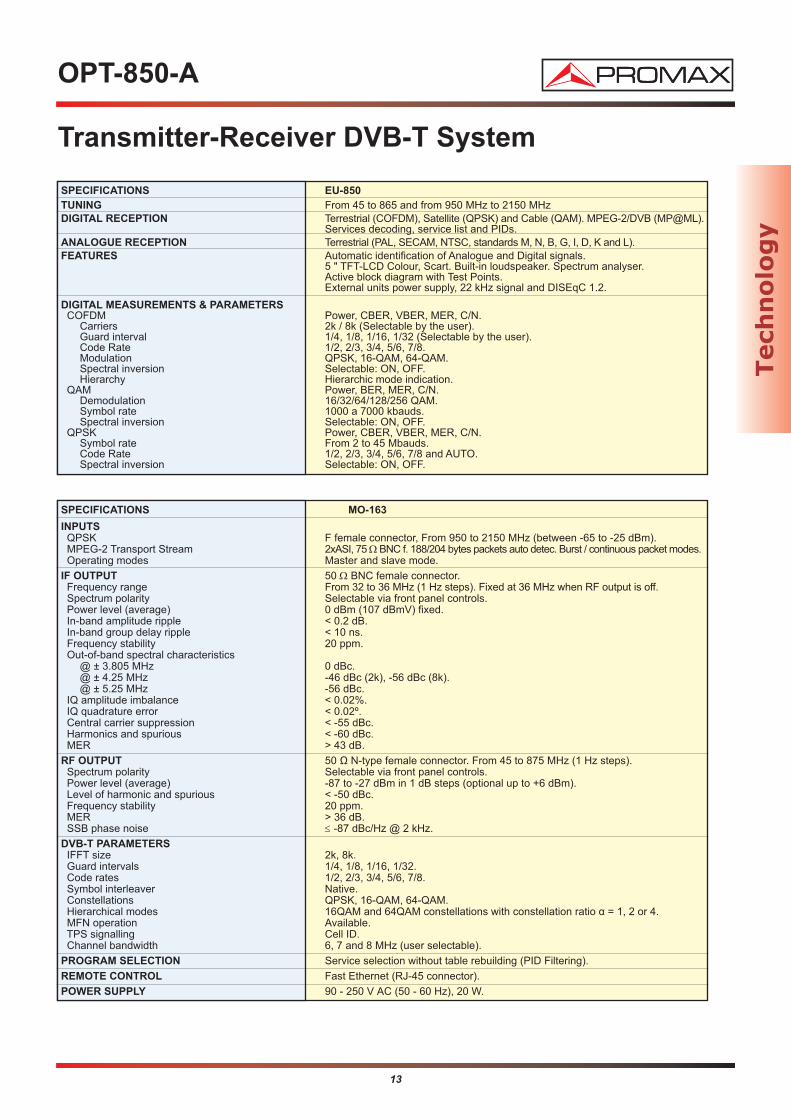
SPECIFICATIONS MO-163
INPUTSQPSK F female connector, From 950 to 2150 MHz (between -65 to -25 dBm).MPEG-2 Transport Stream 2xASI, 75 ΩBNC f. 188/204 bytes packets auto detec. Burst / continuous packet modes.Operating modes Master and slave mode.
IF OUTPUT 50 Ω BNC female connector.Frequency range From 32 to 36 MHz (1 Hz steps). Fixed at 36 MHz when RF output is off.Spectrum polarity Selectable via front panel controls.Power level (average) 0 dBm (107 dBmV) fixed.In-band amplitude ripple < 0.2 dB.In-band group delay ripple < 10 ns.Frequency stability 20 ppm.Out-of-band spectral characteristics
@ ± 3.805 MHz 0 dBc.@ ± 4.25 MHz -46 dBc (2k), -56 dBc (8k).@ ± 5.25 MHz -56 dBc.
IQ amplitude imbalance < 0.02%.IQ quadrature error < 0.02º.Central carrier suppression < -55 dBc.Harmonics and spurious < -60 dBc.MER > 43 dB.
RF OUTPUT 50 Ω N-type female connector. From 45 to 875 MHz (1 Hz steps).Spectrum polarity Selectable via front panel controls.Power level (average) -87 to -27 dBm in 1 dB steps (optional up to +6 dBm).Level of harmonic and spurious < -50 dBc.Frequency stability 20 ppm.MER > 36 dB.SSB phase noise ≤ -87 dBc/Hz @ 2 kHz.
DVB-T PARAMETERS IFFT size 2k, 8k.Guard intervals 1/4, 1/8, 1/16, 1/32.Code rates 1/2, 2/3, 3/4, 5/6, 7/8.Symbol interleaver Native.Constellations QPSK, 16-QAM, 64-QAM.Hierarchical modes 16QAM and 64QAM constellations with constellation ratio α = 1, 2 or 4.MFN operation Available.TPS signalling Cell ID.Channel bandwidth 6, 7 and 8 MHz (user selectable).
PROGRAM SELECTION Service selection without table rebuilding (PID Filtering).
REMOTE CONTROL Fast Ethernet (RJ-45 connector).
POWER SUPPLY 90 - 250 V AC (50 - 60 Hz), 20 W.
SPECIFICATIONS EU-850
TUNING From 45 to 865 and from 950 MHz to 2150 MHzDIGITAL RECEPTION Terrestrial (COFDM), Satellite (QPSK) and Cable (QAM). MPEG-2/DVB (MP@ML).
Services decoding, service list and PIDs.ANALOGUE RECEPTION Terrestrial (PAL, SECAM, NTSC, standards M, N, B, G, I, D, K and L).FEATURES Automatic identification of Analogue and Digital signals.
5 " TFT-LCD Colour, Scart. Built-in loudspeaker. Spectrum analyser.Active block diagram with Test Points.External units power supply, 22 kHz signal and DISEqC 1.2.
DIGITAL MEASUREMENTS & PARAMETERSCOFDM Power, CBER, VBER, MER, C/N.
Carriers 2k / 8k (Selectable by the user).Guard interval 1/4, 1/8, 1/16, 1/32 (Selectable by the user).Code Rate 1/2, 2/3, 3/4, 5/6, 7/8.Modulation QPSK, 16-QAM, 64-QAM.Spectral inversion Selectable: ON, OFF.Hierarchy Hierarchic mode indication.
QAM Power, BER, MER, C/N.Demodulation 16/32/64/128/256 QAM.Symbol rate 1000 a 7000 kbauds.Spectral inversion Selectable: ON, OFF.
QPSK Power, CBER, VBER, MER, C/N.Symbol rate From 2 to 45 Mbauds.Code Rate 1/2, 2/3, 3/4, 5/6, 7/8 and AUTO.Spectral inversion Selectable: ON, OFF.
Tech
no
log
y

14
ET-836
Telephony Training System
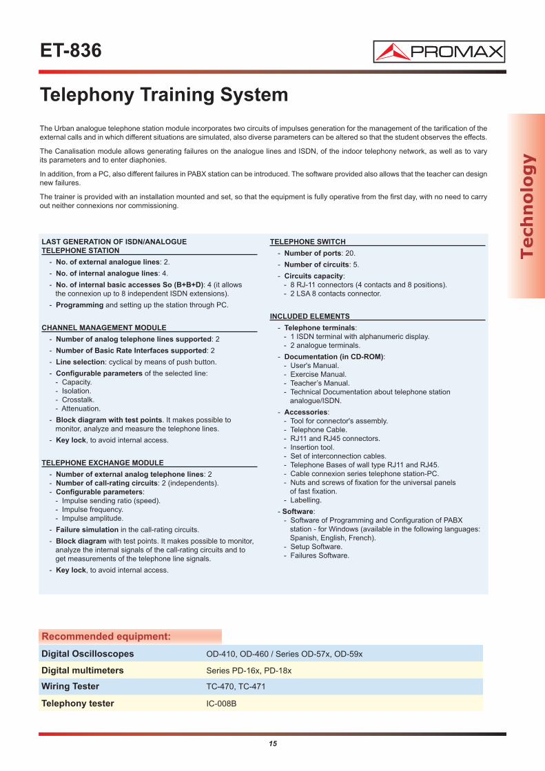
The Telephony Trainer ET-836 is an educational integral system destined to the learning of the theory and the practiseof PABX stations, the indoor telephony networks and the telephony systems, as well as to the development of the skillsof installation and assembly.It works as a standalone training system, with no need of any telephone line for the trainee sessions. The system is capable of carry out internal calls and also to simulate, transparently to the user, incoming or outgoing calls from outside the system.
The training system is fully configurable, based on awhite slate support with removable universal panels of fast fixation, composed by the following elements:
Last generation of PABX station, with 2 external analogue lines, 4 indoor analogue lines and 4 ISDN lines (basic access So: B+B+D).
Urban Central module (which incorporates tarification circuits controlable by the user) that provides 2 external lines, simulating an urban analogue central telephone office, and allows thegeneration of failures.
Canalisation Module that allows the generation of failures on the internal telephone lines and the variation of its parameters.
Telephone distributor, for the interconnection and allocation of lines.
Also are included telephone bases for the connexion of the analogue terminals and RDSI are included, cables, connectors and tools to implement any typologyof telephony network.
The fast fixation universal panels have their surface grooved, of such form that the disposition of the drills combined with the positioning of the nuts allows the fixation of all the provided elements, with the exception of the telephone terminals.
Each one of the ET-836 modules has an active block diagram, with telephone connectors and test points, that allow the connexion of telephone lines and the terminals. In the test points the telephonesignals can be observed, to analyse their different states and to measure their parameters. Also they allow the study of the typical errors of wiring.
PABX station can be connected to a PC, via modem or directly, throughSoftware of Programming and Configuration.
From his PC, the student can control, analyze and configure the management of the PABX system. Software also can run off-line
so that they can be made practices of programming in any PC
with no need of the trainer..
The Urban analogue telephone station module, simulates the externalanalogue lines of a public telephone station, so that they can be generated external calls or to receive outer calls independently, with no need to require of the hiring of real telephone lines.
Tech
no
log
y
15
ET-836
Telephony Training System
LAST GENERATION OF ISDN/ANALOGUE
TELEPHONE STATION
- No. of external analogue lines: 2.
- No. of internal analogue lines: 4.
- No. of internal basic accesses So (B+B+D): 4 (it allows the connexion up to 8 independent ISDN extensions).
- Programming and setting up the station through PC.
CHANNEL MANAGEMENT MODULE
- Number of analog telephone lines supported: 2
- Number of Basic Rate Interfaces supported: 2
- Line selection: cyclical by means of push button.
- Configurable parameters of the selected line:- Capacity.- Isolation.- Crosstalk.- Attenuation.
- Block diagram with test points. It makes possible to monitor, analyze and measure the telephone lines.
- Key lock, to avoid internal access.
TELEPHONE EXCHANGE MODULE
- Number of external analog telephone lines: 2- Number of call-rating circuits: 2 (independents).- Configurable parameters:
- Impulse sending ratio (speed).- Impulse frequency.- Impulse amplitude.
- Failure simulation in the call-rating circuits.
- Block diagram with test points. It makes possible to monitor,analyze the internal signals of the call-rating circuits and to get measurements of the telephone line signals.
- Key lock, to avoid internal access.
TELEPHONE SWITCH
- Number of ports: 20.
- Number of circuits: 5.
- Circuits capacity: - 8 RJ-11 connectors (4 contacts and 8 positions).- 2 LSA 8 contacts connector.
INCLUDED ELEMENTS
- Telephone terminals:- 1 ISDN terminal with alphanumeric display.- 2 analogue terminals.
- Documentation (in CD-ROM):- User's Manual.- Exercise Manual.- Teacher’s Manual.- Technical Documentation about telephone station
analogue/ISDN.
- Accessories:- Tool for connector's assembly.- Telephone Cable.- RJ11 and RJ45 connectors.- Insertion tool.- Set of interconnection cables.- Telephone Bases of wall type RJ11 and RJ45.- Cable connexion series telephone station-PC.- Nuts and screws of fixation for the universal panels
of fast fixation.- Labelling.
- Software:- Software of Programming and Configuration of PABX
station - for Windows (available in the following languages: Spanish, English, French).
- Setup Software.- Failures Software.
Recommended equipment:
Digital Oscilloscopes OD-410, OD-460 / Series OD-57x, OD-59x
Digital multimeters Series PD-16x, PD-18x
Telephony tester IC-008B
Wiring Tester TC-470, TC-471
The Urban analogue telephone station module incorporates two circuits of impulses generation for the management of the tarification of theexternal calls and in which different situations are simulated, also diverse parameters can be altered so that the student observes the effects.
The Canalisation module allows generating failures on the analogue lines and ISDN, of the indoor telephony network, as well as to vary its parameters and to enter diaphonies.
In addition, from a PC, also different failures in PABX station can be introduced. The software provided also allows that the teacher can designnew failures.
The trainer is provided with an installation mounted and set, so that the equipment is fully operative from the first day, with no need to carryout neither connexions nor commissioning.
Tech
no
log
y

16
Tech
no
log
y
EA-817 A
Universal Advanced Antenna Trainer
The trainer is supplied with a real installation, which is assembled and configured, so the equipment is operative from the first day. After finishing the practice, the implemented installation can be take apart quickly, so the trainer will be ready to assemble again another installation.
The trainer can be expanded with other modules to explore in more detail the new technologies and ultrafast
access infrastructures: DVB-S2, Transmodulation, pay-DTT, IP-TV, Fiber Optics, FTTx... as well as DTT real signal transmission.
ANTENNAS
- UHF Antenna UHF- Off-set Antenna (composed by reflector, 4 outputs LNB with polariser, LNB support and fasteners).
MECHANICAL ACCESSORIES
- 150 cm mast for terrestrial antenna- 80 cm mast for off-set antenna- Mobile support for antennas
INTEGRATED MATV HEADEND EQUIPMENT
- Set of 10 UHF programmable filters- VHF and FM amplifier- Power supply unit
COLLECTIVE and INDIVIDUAL MATV DISTRIBUTION
- Splitter, taps, user access point, terminal box, socket divider
COLLECTIVE and INDIVIDUAL SMATV DISTRIBUTION VIA IF
- Switchable splitter, with internal amplifier- IF sockets
USER EQUIPMENT
- High Definition Terrestrial and Satellite digital TV receiver (COFDM and QPSK) with MPEG-2 and MPEG-4 combo
ACCESSORIES FOR ANTENNA POINTING
- Inclinometer and compass
ACCESSORIES, CABLES AND TOOLS
- Reel of coaxial cable (25 m.)- Connectors: 100xF male, 25xTV male, 25xTV female- Tool for coaxial cables- Whiteboard markers (2 pcs)- Nuts and screws for quick mounting on universal panels
INSTRUMENTATION
- Simulator for Intermediate Frequency (RP-050)
DOCUMENTATION (on CD-ROM)
- Theory and Practice Manual for Intermediate Cycle- Trainer’s User’s Manual- Technical Documentation- Assembly Instructions
The Antenna Trainer EA-817 A (advanced) is a comprehensive education system designed for teaching, demonstration and experimentation about the theory andpractice of telecommunications infrastructure installations:
- MATV (Master Antenna Television) Digital - SMATV (Satellite Master Antenna Television) Digital
... and the development of skills to install and assembly. It isbased on a structure with whiteboard panels, each oneconsisting of two universal quick-fixing removable boards. It allows the student to install, configure, adjust, modify andanalyse any kind of actual MATV and SMATV installation.
Recommended equipment:
TV signal generators GV-998, GV-898+, GV-798, GV-698+
Field strength meters TV EXPLORER, TV EXPLORER II, II+, HD and HD+
COFDM Modulators MO-170, Digital To TV (DTTV) headend
Test signal generators Model RP-110
TERRESTRIAL SATELLITE CABLE

17
Tech
no
log
y
EA-817 B
Basic Universal Antenna Trainer
Recommended equipment:
TV signal generators GV-998, GV-898+, GV-798, GV-698+
Field strength meters TV EXPLORER, TV EXPLORER II, II+, HD and HD+
COFDM Modulators MO-170, Digital To TV (DTTV) headend
Test signal generators Model RP-110
Sometimes, the antenna trainer must be mounted on a fixedsurface, making it unnecessary to dispose of quick-fixingremovable boards.
For these cases, PROMAX offers the Basic Universal
Antenna Trainer that dispenses with these elements,while facilitating the transport and storage of the trainer, taking up less space.
The functionality and connections flexibility are identical to those of Advanced Trainer, as well as expansion
capabilities for new technologies and DTT real signal transmission.
ANTENNAS
- UHF antenna- Off-set antenna (composed by reflector, 4 outputs LNB with polariser and LNB fasteners).
MECHANICAL ACCESSORIES
- 150 cm mast for terrestrial antenna- Fixed support for off-set antenna
INTEGRATED MATV HEADEND EQUIPMENT
- Set of 10 UHF programmable filters- VHF and FM amplifier- Power supply unit
COLLECTIVE and INDIVIDUAL MATV DISTRIBUTION
- Splitter, taps, user access point, terminal box, terminal boxcover, socket divider.
COLLECTIVE and INDIBIDUAL SMATV DISTRIBUTION VIA IF
- Switchable splitter, with internal amplifier- IF sockets
USER EQUIPMENT
- High Definition Terrestrial and Satellite digital TV receiver(COFDM and QPSK) with MPEG-2 and MPEG-4 combo
ACCESSORIES FOR ANTENNA POINTING
- Inclinometer and compass
ACCESSORIES, CABLES AND TOOLS
- Reel of coaxial cable (25 m.)- Connectors: 100xF male, 25xTV male, 25xTV female- Tool for coaxial cables
INSTRUMENTATION
- Simulator for intermediate frequency (RP-050)
DOCUMENTATION (on CD-ROM)
- Theory and Practice Manual- Trainer’s User’s Manual- Technical Documentation
The Antenna Trainer EA-817 B (basic) is a comprehensiveeducation system designed for teaching, demonstration and experimentation about the theory and practice of telecommunicacions infrastructure installations:
- MATV (Master Antenna Television) Digital - SMATV (Satellite Master Antenna Television) Digital
... and the development of skils to install and assembly. This trainer allows students to install, configure, adjust, modify and analyse any real MATV and SMATV installation.
TERRESTRIAL SATELLITE CABLE
Includes test signal
generator RP-050
Including satellite
dish and UHF
Super selective
headend model AGILincluded

18
ET-893
Flat Screen Digital Terrestrial TV Training System
With a wide number of test points, makes possible a thorough analysis and tracking of the electrical signals in thedifferent blocks from the receiver. All the test points are protected against accidental short-circuits. By means of the failures module it is possible to simulate the more frequent failures than they can take place in the receiverin order that the student learns to carry out methods of diagnosis and trouble-shooting.
Special attention has been dedicated to develop a fully functional design with a small size.
The ET-893 is a suitable equipment for the learning of the flat screentelevision sets operation equipped with TFT-LCD and Plasma technology that allows the student to become familiar with the moreadvanced technological innovations, likewise for the reception of Digital Terrestrial Television (DVB-T). The trainer includes a failures generation module.
The ET-893 block diagram shows through an intuitive way the differentstages that compounds the flat screen receiver.
TV TFT-LCD RECEIVER
- Screen size 20''.- 4:3 format.- Resolution: 640x480 pixels.- TV systems: PAL B/G/I/D/K and SECAM B/G/D/K/L/L'.- Scart connector.- Two A/V outputs: SVHS, L/R and Video.- Audio Output: L/R Out.- Earphone output.- PC connexion: VGA connector and audio mini-jack connector.- Audio analogue Zweiton system (PAL G).- Audio digitalis system NICAM (PAL G).- Teletext.- On Screen Display (OSD).- Remote Control by IR.
FAILURES SIMULATOR
A set of microswitches allows to cause a wide number of real failures on the TV receiver, in such a way that the teacher is able to evaluate the student’s ability to diagnose and find the failure.
BLOCK DIAGRAM
The block diagram is made up of the following functional module:- Power supply.- DVB-T.- IF and Demodulador.- Video Processing.- Audio Processing.- System Control.- Inputs/Outputs.- Climbing circuit.
DOCUMENTATION INCLUDED (IN CD-ROM)
- Training Manual.- Teacher's Manual.- Exercises Manual.- Technical Documentation and Circuits Description Manual.
ACCESSORIES
- Remote control.- Batteries (Two R6 AA units).- Scart connector cable.
(*) Also available ET-892, without built-in Digital Terrestrial TV receiver (DVB-T).
Recommended equipment:
TV signal generators GV-998, GV-898+, GV-798+, GV-698+
COFDM Modulators MO-170, MO-163
Digital Oscilloscopes OD-410, OD-460 / Series OD-57x, OD-59x
Field strength meters TV Explorer, TV Explorer II / II+, PROLINK-3C/4C Premium
Trade Mark of the DVB Digital Video Broadcasting Project (6226)
TERRESTRIAL
Con
sum
er

EV-830
Video Cassete Recorder Training system
19
VIDEO RECORDER-PLAYER
The EV-830 incorporates a VHS video recorder manufactured withthe most advanced technology, equipped with a high level of features and with a wide diffusion on the market. From among its characteristics we can highlight:
- PAL system.- Automatic tuning.- Two heads.- Self-cleaning.- Auto-tracking digital.- Euroconnector.- Frame-by-frame and pause.- Automatic System for failure detection.
BLOCK DIAGRAMS
The block diagrams consist of the following functional modules,each one with the test points of the most important electric signalsinvolved in its operation:
- Tuning.- Video.- Sound.- Servosystems.- Control System.- Power supply.
FAULT SIMULATOR
The fault simulator manipulates electric points of the video, allowinga large number of test points to be simulated, in such a way that the teacher is able to evaluate the student’s ability to diagnose and find the failure.
INCLUDED DOCUMENTATION (in CD-ROM)
- User’s Manual.- Training Manual.- Electric diagrams and Technical Documentation.
The following documentation is also included (in paper):- Theory Manual.- Video Recorder-Player User’s Manual.
ACCESSORIES
- Video Pattern Tape.- Connection cables.
Recommended equipment:
Digital Oscilloscopes OD-410, OD-460 / Series OD-57x, OD-59x
TV signal generators GV-898+, GV-798+, GV-698+
Field strength meters TV Explorer, TV Explorer II / II+, PROLINK-3C/4C Premium
The EV-830 has been designed on a multifunctional support which aids the analysis of the most important electric signals in the different modes of operationof the video, the inspection of all the movements of the mechanical elements andthe simulation of the most frequent faults. Under the upper cover of the equipment, there areblock diagrams of the video with a large number of test points which allow the visualisation and monitoringof the different electric signals in any mode of operation.
All the test points are protected against possible accidental short-circuits. The units can be stacked with the rest of the range and in their rest position they can be used as domestic desktop instruments.
The EV-830 video cassete trainer is a teaching equipment intended for training Professional students in an easy and enjoyable manner,which makes them possible to assimilate the operation and the repairtechniques of VHS video equipment. It is accompanied by extensive documentation which includes User’s Manual, Training Manual, Block Diagrams and Technical Documentation
Con
sum
er
20
ED-845
DVD and CD Trainer (Region 2)
Con
sum
er
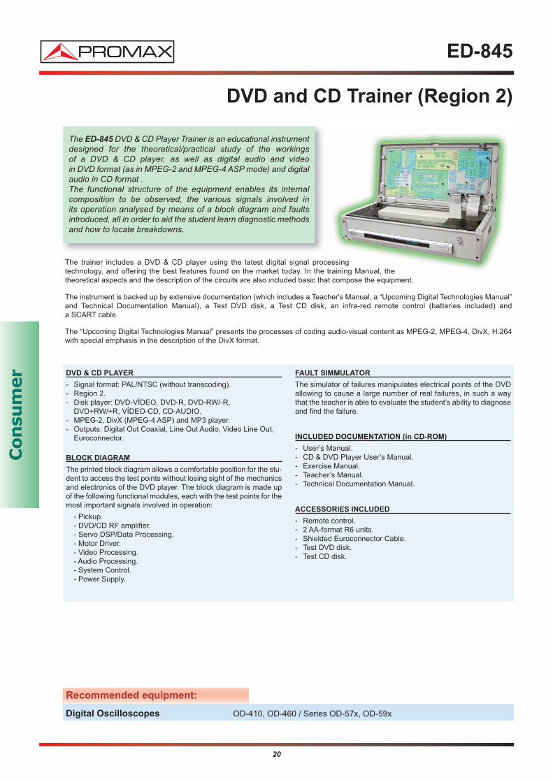
The ED-845 DVD & CD Player Trainer is an educational instrumentdesigned for the theoretical/practical study of the workings of a DVD & CD player, as well as digital audio and video in DVD format (as in MPEG-2 and MPEG-4 ASP mode) and digitalaudio in CD format . The functional structure of the equipment enables its internal composition to be observed, the various signals involved in its operation analysed by means of a block diagram and faults introduced, all in order to aid the student learn diagnostic methodsand how to locate breakdowns.
The trainer includes a DVD & CD player using the latest digital signal processing technology, and offering the best features found on the market today. In the training Manual, the theoretical aspects and the description of the circuits are also included basic that compose the equipment.
The instrument is backed up by extensive documentation (which includes a Teacher's Manual, a “Upcoming Digital Technologies Manual”and Technical Documentation Manual), a Test DVD disk, a Test CD disk, an infra-red remote control (batteries included) and a SCART cable.
The “Upcoming Digital Technologies Manual” presents the processes of coding audio-visual content as MPEG-2, MPEG-4, DivX, H.264with special emphasis in the description of the DivX format.
DVD & CD PLAYER
- Signal format: PAL/NTSC (without transcoding).- Region 2.- Disk player: DVD-VÍDEO, DVD-R, DVD-RW/-R,
DVD+RW/+R, VÍDEO-CD, CD-AUDIO.- MPEG-2, DivX (MPEG-4 ASP) and MP3 player.- Outputs: Digital Out Coaxial, Line Out Audio, Video Line Out,
Euroconnector.
BLOCK DIAGRAM
The printed block diagram allows a comfortable position for the stu-dent to access the test points without losing sight of the mechanicsand electronics of the DVD player. The block diagram is made upof the following functional modules, each with the test points for themost important signals involved in operation:
- Pickup.- DVD/CD RF amplifier.- Servo DSP/Data Processing.- Motor Driver.- Video Processing.- Audio Processing.- System Control.- Power Supply.
FAULT SIMMULATOR
The simulator of failures manipulates electrical points of the DVDallowing to cause a large number of real failures, in such a way that the teacher is able to evaluate the student’s ability to diagnoseand find the failure.
INCLUDED DOCUMENTATION (in CD-ROM)
- User’s Manual.- CD & DVD Player User’s Manual.- Exercise Manual.- Teacher’s Manual.- Technical Documentation Manual.
ACCESSORIES INCLUDED
- Remote control.- 2 AA-format R6 units.- Shielded Euroconnector Cable.- Test DVD disk.- Test CD disk.
Recommended equipment:
Digital Oscilloscopes OD-410, OD-460 / Series OD-57x, OD-59x

EG-833
Cassette Recorder Training System
21
Con
sum
er
The EG-833 Trainer is an educational instrument designed for the theoretical/practical study of the operation of the cassette recorder/player magnetic systems, as well as the noise reductionsystem.
The trainer EG-833 is based on a high quality cassette recorder, with the most advanced recording, playback, polarization and noise reduction (Dolby B and C) circuits.
The large number of test points allows a detailed analysis of the main signals involved in different processes.
BLOCK DIAGRAMS
The block diagrams consist of the following functional modules:- Input section.- Recording process section.- Playback process section.- Output section.- Noise reduction systems: Dolby© B and C.- Control system.- Servos.- Automatic Music Search (AMS).- Power supply.- Fluorescent visualiser.
FAULT SIMULATOR
The fault simulator manipulates electric points of the cassettedeck, allowing to simulate real faults, in such a way that the teacher is able to evaluate the student’s ability to diagnoseand find the failure.
The fault simulator manipulates electric points of the cassettedeck, allowing to simulate real failures.
INCLUDED DOCUMENTATION (in CD-ROM)
- User’s Manual.- Training Manual.- Teacher’s Manual (Failures).- Electric diagrams and Technical Documentation.
The following documentation is also included (in paper):- Cassete Recorder User’s Manual.
ACCESORIES
- Auto-amplified speakers.- Test Tape.- Connection cables.
MAGNETIC CASSETTE RECORDER/PLAYER
- Double Tape.
- Dolby© B and C.
- Automatic Tape Selector(ATS).
- Automatic Recording Leveladjustment (ARL).
- Gradual rise and fade of the sound (FADER).
- Blank space insertion.
- Signal level indicator.
- Automatic Music Search (AMS).
- Selectable MPX filter.
- Headphone outputs.
- Synchronized recording.
Recommended equipment:
Digital Oscilloscopes OD-410, OD-460 / Series OD-57x, OD-59x
Function Generator GF-232, GF-230, GF-941
22
ER-832
Radio Training System
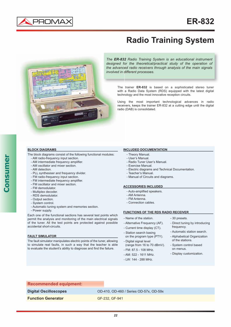
The ER-832 Radio Training System is an educational instrument designed for the theoretical/practical study of the operation of the advanced radio receivers through analysis of the main signals involved in different processes.
The trainer ER-832 is based on a sophisticated stereo tuner with a Radio Data System (RDS) equipped with the latest digital technology and the most innovative reception circuits.
Using the most important technological advances in radio receivers, keeps the trainer ER-832 at a cutting edge until the digitalradio (DAB) is consolidated.
BLOCK DIAGRAMS
The block diagrams consist of the following functional modules:- AM radio-frequency input section.- AM intermediate frequency amplifier.- AM oscillator and mixer section.- AM detection.- PLL synthesiser and frequency divider.- FM radio-frequency input section.- FM intermediate frequency amplifier.- FM oscillator and mixer section.- FM demodulator.- Multiplex decoder.- RDS demodulator.- Output section.- System control.- Automatic tuning system and memories section.- Power supply.
Each one of the functional sections has several test points whichpermit the analysis and monitoring of the main electrical signals of the tuner. All the test points are protected against possible accidental short-circuits.
FAULT SIMULATOR
The fault simulator manipulates electric points of the tuner, allowingto simulate real faults, in such a way that the teacher is able to evaluate the student’s ability to diagnose and find the failure.
INCLUDED DOCUMENTATION
- Theory Manual.- User’s Manual.- Radio Tuner User’s Manual.- Exercise Manual.- Electric diagrams and Technical Documentation.- Teacher’s Manual.- Manual of Circuits and diagrams.
ACCESSORIES INCLUDED
- Auto-amplified speakers.- AM Antenna.- FM Antenna.- Connection cables.
FUNCTIONS OF THE RDS RADIO RECEIVER
- Name of the station.
- Alternative Frequency (AF).
- Current time display (CT).
- Station search basing on the program type (PTY).
- Digital signal level (range from 16 to 70 dBmV).
- FM: 87.5 - 108 MHz.
- AM: 522 - 1611 MHz.
- LW: 144 - 288 MHz.
- 30 presets.
- Direct tuning by introducingfrequency.
- Automatic station search.
- Alphabetical Organization of the stations.
- System control based on menus.
- Display customization.
Recommended equipment:
Digital Oscilloscopes OD-410, OD-460 / Series OD-57x, OD-59x
Function Generator GF-232, GF-941
Con
sum
er

23
EP-834
Amplifier Training System
The EP-834 is the proper equipment to study the theoretical and practical aspects of the power amplifiers through the analysis of the signals involved in the different functional processes.
The trainer EP-834 is based on a high quality power amplifier, with the most advanced technology and design, using a hybrid powerstage. It includes two resistive loads (8Ω - 300W) which allow simulating the connection of the speakers.
BLOCK DIAGRAMS
The block diagrams consist of the following functional modules,each with the test points for the most important signals involved inthe operation:
- Input signal source.- Input signal source control.- System control.- RIIA correction.- Loudness filter.- Subsonic filter.- Tone control and physiological filter.- Power section.- Speakers protections.- Power supply.
Each one of the functional sections have several test points whichpermit the analysis and monitoring of the main electrical signals of the amplifier.
FAULT SIMULATOR
The fault simulator manipulates electric points of the amplifier, allowing to simulate a large number of real faults, so that the teacher can evaluate the diagnostic process performed by the student and therefore the degree of assimilation of the basic concepts studied.
INCLUDED DOCUMENTATION (in CD-ROM)
- User’s Manual.- Training Manual.- Teacher’s Manual.- Electric diagrams and Technical Documentation.
The following documentation is also included (in paper):- Theory Manual.- Power Amplifier User’s Manual.
ACCESSORIES
- Loads 8 Ω - 300 W (2 units).- Remote control.- Batteries (2 units R6 AA).- Headphones + Adapter.
POWER AMPLIFIER
- Hybrid amplification.
- DIN power output (4Ωat 1 kHz): 70 W + 70 W.
- Protection against shortcircuits.
- Tone control: bass and treble.
- Loudness control.
- Balance adjustment.
- 6 audio inputs.
- Source Direct (to listendirectly to the input signal).
- Tape monitor.
- Headphone output:- PHONO (20 Hz - 20 kHz):
RIAA equalisation curve± 1 dB.
- TUNER, CD, AUX, TAPE1 / DAT, TAPE 2 / MD: 7 Hz - 70 kHz ± 0,3 dB.
- S/N ratio:- PHONO: 80 dB.- TUNER, CD, AUX, TAPE1
/ DAT, TAPE 2 / MD: 105 dB.
- Impedance of the speakers: 4 - 16 Ω.
Recommended equipment:
Digital Oscilloscopes OD-410, OD-460 / Series OD-57x, OD-59x
Function Generators GF-232, GF-230, GF-941
Con
sum
er
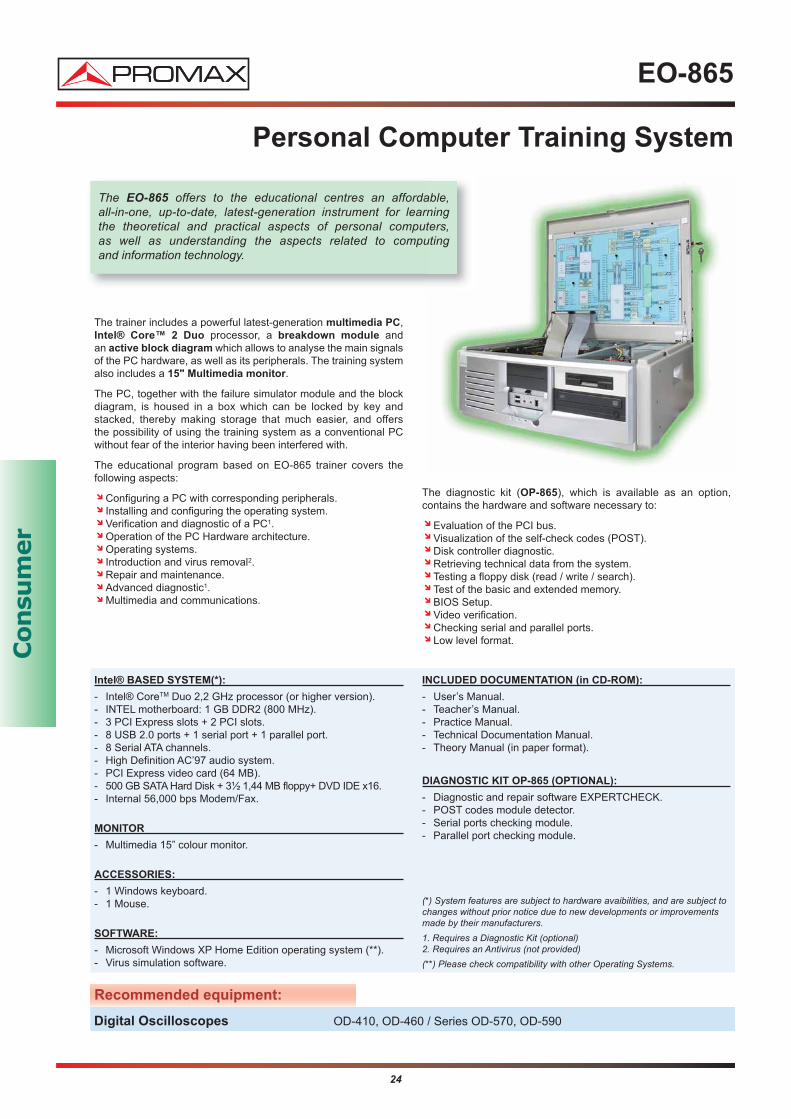
The trainer includes a powerful latest-generation multimedia PC,Intel® Core™ 2 Duo processor, a breakdown module and an active block diagram which allows to analyse the main signalsof the PC hardware, as well as its peripherals. The training systemalso includes a 15" Multimedia monitor.
The PC, together with the failure simulator module and the blockdiagram, is housed in a box which can be locked by key and stacked, thereby making storage that much easier, and offers the possibility of using the training system as a conventional PCwithout fear of the interior having been interfered with.
The educational program based on EO-865 trainer covers the following aspects:
Configuring a PC with corresponding peripherals.Installing and configuring the operating system.Verification and diagnostic of a PC1.Operation of the PC Hardware architecture.Operating systems.Introduction and virus removal2.Repair and maintenance.Advanced diagnostic1.Multimedia and communications.
The diagnostic kit (OP-865), which is available as an option, contains the hardware and software necessary to:
Evaluation of the PCI bus. Visualization of the self-check codes (POST).Disk controller diagnostic.Retrieving technical data from the system.Testing a floppy disk (read / write / search).Test of the basic and extended memory.BIOS Setup.Video verification.Checking serial and parallel ports.Low level format.
24
EO-865
Personal Computer Training System
Intel® BASED SYSTEM(*):
- Intel® CoreTM Duo 2,2 GHz processor (or higher version).- INTEL motherboard: 1 GB DDR2 (800 MHz).- 3 PCI Express slots + 2 PCI slots.- 8 USB 2.0 ports + 1 serial port + 1 parallel port.- 8 Serial ATA channels.- High Definition AC’97 audio system.- PCI Express video card (64 MB).- 500 GB SATA Hard Disk + 3½ 1,44 MB floppy+ DVD IDE x16.- Internal 56,000 bps Modem/Fax.
MONITOR
- Multimedia 15” colour monitor.
ACCESSORIES:
- 1 Windows keyboard.- 1 Mouse.
SOFTWARE:
- Microsoft Windows XP Home Edition operating system (**).- Virus simulation software.
INCLUDED DOCUMENTATION (in CD-ROM):
- User’s Manual.- Teacher’s Manual.- Practice Manual.- Technical Documentation Manual.- Theory Manual (in paper format).
DIAGNOSTIC KIT OP-865 (OPTIONAL):
- Diagnostic and repair software EXPERTCHECK.- POST codes module detector.- Serial ports checking module.- Parallel port checking module.
(*) System features are subject to hardware avaibilities, and are subject tochanges without prior notice due to new developments or improvementsmade by their manufacturers.1. Requires a Diagnostic Kit (optional)2. Requires an Antivirus (not provided)(**) Please check compatibility with other Operating Systems.
Recommended equipment:
Digital Oscilloscopes OD-410, OD-460 / Series OD-570, OD-590
The EO-865 offers to the educational centres an affordable, all-in-one, up-to-date, latest-generation instrument for learning the theoretical and practical aspects of personal computers, as well as understanding the aspects related to computing and information technology.
Con
sum
er
25
TM-530
Application Programming and Development Trainer
with Programmable Logic Devices
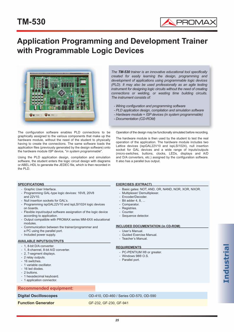
The TM-530 trainer is an innovative educational tool specificallycreated for easily learning the design, programming and development of applications using programmable logic devices(PLD). It may also be used professionally as an agile testing instrument for designing logic circuits without the need of creatingconnections or welding, or wasting time building circuits. The instrument consists of:
- Wiring configuration and programming software- PLD application design, compilation and simulation software - Hardware module + ISP devices (in system programmable)- Documentation (CD-ROM)
The configuration software enables PLD connections to be graphically assigned to the various components that make up thehardware module, without the need of the student to physically having to create the connections. The same software loads the application files (previously generated by the design software) ontothe hardware module ISP device, "in system programmable".
Using the PLD application design, compilation and simulation software, the student enters the logic circuit design with diagrams or ABEL-HDL to generate the JEDEC file, which is then recorded inthe PLD.
Operation of the design may be functionally simulated before recording.
The hardware module is then used by the student to test the realoperation of the application. The hardware module includes two Lattice devices (ispGAL22V10 and ispLSI1024), null insertion socket for GAL devices and a wide range of inputs/outputs (micro-switches, buttons, clocks, LEDs, displays and A/D and D/A converters, etc.) assigned by the configuration software. It also has a parallel bus output.
SPECIFICATIONS
- Graphic User Interface.- Programming GAL-type logic devices: 16V8, 20V8
and 22V10.- Null insertion sockets for GAL’s.- Programming ispGAL22V10 and ispLSI1024 logic devices
on boards.- Flexible input/output software assignation of the logic device
according to application.- Output compatible with PROMAX series MM-6XX educational
modules.- Communication between the trainer/programmer and
a PC using the parallel port.- Included power supply.
AVAILABLE INPUTS/OUTPUTS
- 1, 8-bit D/A converter.- 1, 8-channel, 8-bit A/D converter.- 2, 7-segment displays.- 2 relay outputs.- 16 switches.- 1 variable oscillator.- 16 led diodes.- 2 buttons.- 1 hexadecimal keyboard.- 1 application connector.
EXERCISES (EXTRACT)
- Basic gates: NOT, AND, OR, NAND, NOR, XOR, NXOR.- Multiplexer/ Demultiplexer.- Encoder/Decoder.- Bit adder 4, 8, ...- Comparator.- Registries.- Counter.- Sequence detector.
INCLUDED DOCUMENTATION (in CD-ROM)
- User’s Manual.- Guided Exercise Manual.- Teacher’s Manual.
REQUIREMENTS
- PC-PENTIUM II® or greater.- Windows 98® O.S.- Parallel port.
Recommended equipment:
Digital Oscilloscopes OD-410, OD-460 / Series OD-570, OD-590
Function Generator GF-232, GF-230, GF-941
Ind
ust
rial

26
Ind
ust
rial
The IC-003 consists of:
MICROPIC TRAINER: Development system.MICROPICTRAINER PLUS: Peripherals expansion card.PICS I DESIGN COURSE: PIC design practical course.
The whole thing is mounted on a methacrylate board for easy use,transport and storage.
The MICROPIC LAB PLUS allows for training on and the design of projects ranging from the simplest ideas to the most spectacularapplications using a multitude of peripherals and advanced communications protocols such as RS-232 and I2C buses.
In industrial design tasks, the instrument provides all the hardwareand software resources that are normally required for the development of any system. The device includes a practical designcourse employing PICs, which has been specifically created forthose who are beginning microcontroller design, in mind. All theexercises are carried out using the PIC16F84 and the MICROPIC
TRAINER and MICRO PIC TRAINER PLUS tools, in combination with either the SIMUPIC'84 or the MPLAB simulator.
IC-003
Micropic LAB plus Basic PICS Trainer
(16F84 Family)
The MICROPIC LAB PLUS is an instrument for use by professional and higher educational laboratories, as well as by PIC microcontroller design and engineering firms.
MICROPIC TRAINER
- Diskette containing the control software and applications.
- In-circuit PIC recorder.
- PIC eraser with EPROM and FLASH memories.
- 4 MHz quartz-crystal oscillator and Reset button.
- Cable for connection to the PC parallel port.
- Peripherals to emulate applications: LCD screen, 7-segment display, potentiometers to simulate analogue inputs, switchesand LED diode bar.
- PICBUS expansion connector to adapt to the other modules.
- User manual, with a full tutorial for assembly, set up and handling. Contains various training programs.
- Various types of adapters and complementary resources tomeet the user's needs and the wide range of PIC models.
MICROPIC TRAINER PLUS
- Direct connection to the MICROPIC TRAINER with the included 26-line flat cable and the PICBUS connector.
- RS-232 communications channel with standard connector. If the employed PIC has USART installed, use lines RC6 and RC7, if it is controlled by the software, use RB4 and RB5.
- I2C interface controlled by lines RC3 and RC4 in PICs using an integrated module, and by lines RB6 and RB7 when controlled by the software.
- 4-digit display of 7 segments controlled by integrated circuitI2C, model SAA1064.
- Four AD conversion channels and one DA, supported by the
PCF8591 device.
- 8-digital-line I/O port through I2C device PCF8574.
- Diode bars giving information on the state of the digital lines.
- Real time Clock/Calendar with PCF8583 I2C device powered by a rechargeable Ni/Cd battery that also holds 240 bytes of non-volatile RAM memory.
PICS I DESIGN COURSE
Contents index:
- Subject 1: Programming the PIC16F84 and its Architecture.Collection of exercises using Simupic'84 and/or MPLAB.
- Subject 2: Main Resources: Timer, Switches, I/O, etc. Collection of exercises using the MICROPIC TRAINER.
- Subject 3: New Peripherals and the I2C Bus. Collection of exercises using the MICROPIC and the MICROPIC TRAINER PLUS.
- Annexes: 7 Containing the communications programs and routines, I2C Modules C Programs, etc.
- DISKETTE: Contains the solutions to all the given exercises in Assembler and C languages.
(The Documentation is only available in Spanish language)

27
Ind
ust
rial
IC-004
Advanced PIC Trainer Extension (16F87x family)
There is a wide range of classic applications that are used in industry: motor governors, power control, analogue parameter manipulation, wave train generation, relay activation, etc. Certainspecific resources are employed to support these requirements, therefore the microcontrollers involved in these processes are to befound in a chip.
The average range of PICs contains models with the particular devices needed to accomplish a specific industrial task already installed in the silicone chip. Special mention should be made of the PIC16F87X which includes AD converters, various timers, a UART series channel, an I2C bus, capture and comparison modules, pulse width modulation, etc.
The IC-004 consists of:
MICROPIC IO: Advanced peripherals card (sensors and industrial actuators).
F87x SOCKET: Kit for performing exercises with PIC 16F873.
PIC II DESIGN COURSE: Advanced PIC design practical course.
MICRO PIC IO
The MICROPIC IO card, connected directly to basic PIC trainer IC-003, makes an excellent test bed to analyse and debug the routineswhich control the peripherals and resources commonly used in industry.
In order to help the user get the most out of his MICROPIC IO card, an advanced PIC design practical course is included which contains various exercises, programs and projects, as well as a selection of industrial control routines that may be applied to the MICRO PIC IO modules.
These require the MICROPIC TRAINER, the ZOC87x adapter socket, the MICROPIC TRAINER PLUS and the MICROPIC IO card. The 9 subjects begin with a brief summary of each device and then propose a series of exercises to demonstrate its operation. Special emphasis is given to motor control, the control of analogue sensors using converters, wave generation, power control using triacs, relay activation, FLASH and EPROM program and data recording, etc.
The expansion module IC-004 of the basic PICs trainer IC-003 is aimed at users with a knowledge of the basic principlesinvolved in PIC design laid out in the first part and who now want to learn more about the new, powerful resources contained in the latest models of the PIC16F87x family. All the exercises in this part are carried out usingthe PIC16F873.
MICROPIC IO
- DC motor speed control.- Optical encoder to control motor rotation and speed.- GMultiple wave generator.- Power control using the Triac firing angle.- Illumination control.- Oscillator.- Analogue light and temperature sensors.- Two microrelays.- Piezoelectronic buzzer.- 12 VAC power supply.- Stabilised power source.- Two PICBUS connectors for adapting to other tools.- User’s Manual.
ZOC F87x SOCKET
This is a kit that allows you to control the latest PIC16F87x
resources in the MICROPIC TRAINER using a FLASH memory.Furthermore the adapter socket also includes a PIC16F873 with a recorded demonstration program, the latest version of the PICME-TR program and documentation.
COURSE FOR PICS DESIGN II
- Subject 1: Programming the PIC16F87x and its Architecture.Exercises with I/O ports.
- Subject 2: Timer 1. Exercises.- Subject 3: Timer 2. Exercises.- Subject 4: Capture and Comparison Module. Exercises.- Subject 5: PWM Module. Exercises.- Subject 6: The Analogue/Digital Converter. Exercises.- Subject 7: The MSSP Series Port: UART Mode. Exercises.- Subject 8: Serial Communications using the I2C Bus. Exercises.- Subject 9: Programming and Handling the EPROM
and FLASH. Exercises.- Annexes.
LEADING THE EUROPEAN MARKET IN DESIGN ANDMANUFACTURE OF TEST&MEASUREMENT EQUIPMENT
PROMAX ELECTRONICA, S.A.Francesc Moragas, 71 * Apartado 118 * 08907 L'HOSPITALET DE LLOBREGAT * SPAINTel: 93 184 77 00 * Tel Intl: (+34) 93 184 77 02 * Fax: 93 338 11 26 * Fax intl: (+34) 93 338 11 26http://www.promaxelextronics.com * e-mail:[email protected]
TEST AND MEASUREMENT
* DIGITAL AND ANALOGUE OSCILLOSCOPES
* SIGNAL GENERATORS
* FREQUENCY COUNTERS
* COMPONENTS TESTERS
* POWER SUPPLIES FOR LAB USE
* DIGITAL MULTIMETERS
ANALOGUE AND DIGITAL FIELD STRENGTH METERS FOR DTT /
SERVICE / CATV
* DVB-T/T2, DVB-S/S2 FIELD METERS
* SPECTRUM MONITORS
* CATV ANALYSERS: TV + INTERNET + VoIP
INSTRUMENTS FOR TV&AUDIO TESTING
* TV SIGNAL GENERATORS
* TS (TRANSPORT STREAM) AND DTT (DIGITAL TERRESTRIAL TELEVISION) GENERATORS
* MONITOR TEST GENERATORS
* EQUIPMENT FOR REPAIR SERVICE CENTERS
DTTV DIGITAL TO TV - TV DISTRIBUTION SYSTEM
* DVB-S AND DVB-S2 RECEIVERS
* COFDM MODULATORS
* QPSK-COFDM TRANSMODULATORS
* IP-COFDM TRANSMODULATORS
* DTT REGENERATORS
* A/V-COFDM MULTIPLEXERS
* COMBINERS
* AMPLIFIERS
BROADCAST
* BROADCAST MONITORING
* DVB-T AND DVB-H MONITORING
* TRANSPORT STREAM RECORDERS AND PLAYERS
RF EQUIPMENT
* SPECTRUM ANALYSERS
* RF GENERATORS
* WATTMETERS
* RF IMPEDANCE LOADS
* WI-FI ANALYSERS
TV DISTRIBUTION EQUIPMENT
* MULTIBAND AMPLIFIERS
* SINGLE CHANNEL AMPLIFIERS
* PROGRAMMABLE SUPERSELECTIVE MATV HEADEND
* PROGRAMMABLE MATV HEADEND
* PAL DISTRIBUTION HEADEND
* INDOOR DVB-T MODULATORS
* DTT RECEIVERS
OPTICAL FIBRE INSTRUMENTS
* GPON METER FOR FTTH
* MICRO OTDR WITH LCD COLOR SCREEN
* PORTABLE OPTICAL SPECTRUM ANALYSERS
* LIGHT SOURCES: DOUBLES AND TRIPLES
* SELECTIVE AND NON-SELECTIVE POWER METERS
* OPTICAL FIBRE IDENTIFIER
* FAULT LOCATOR
CABLE TESTERS
* LAN AND TELEPHONE CABLE TRACER
* LAN NETWORKS TESTERS
* LAN NETWORKS CERTIFIERS
* TELEPHONY NETWORKS TESTERS
* DOMOTICS AND CCTV ANALYSERS
ELECTRICAL MEASUREMENT EQUIPMENT
* ELECTRICAL NETWORKS ANALYSERS
* CURRENT AND WATTMETER CLAMPS
* EARTH AND INSULATION METERS
* RCD TESTERS
* SOUND LEVEL AND IMPEDANCE METERS
* LUX METERS AND TACHOMETERS
EDUCATIONAL TRAINERS
* UNIVERSAL DIGITAL TV RECEIVER TRAINERS
* TRAINING SYSTEMS FOR MDUS INFRAESTRUCTURES
* FLAT SCREEN LCD / PLASMA TV TRAINERS
* ANALOGUE AND DIGITAL COMMUNICATIONS TRAINING SYSTEMS
* FIBRE OPTICS TRAINERS
* CONSUMER ELECTRONICS TRAINING SYSTEMS, TV AND VIDEO,AUDIO
* TELEPHONY TRAINERS
DE
SIG
N A
ND
SP
EC
IFIC
AT
ION
S S
UB
JEC
T T
O C
HA
NG
ES
WIT
HO
UT
PR
IOR
NO
TIC
E. 0
9/1
1