technicaltraining. productinformation. …v12.dyndns.org/bmw/bmw i3/07 i01 driver assistance... ·...
TRANSCRIPT

Technical�training.Product�information.
BMW�Service
I01�Driver�Assistance�Systems

General�information
Symbols�used
The�following�symbol�is�used�in�this�document�to�facilitate�better�comprehension�or�to�draw�attentionto�very�important�information:
Contains�important�safety�information�and�information�that�needs�to�be�observed�strictly�in�order�toguarantee�the�smooth�operation�of�the�system.
Information�status�and�national-market�versions
BMW�Group�vehicles�meet�the�requirements�of�the�highest�safety�and�quality�standards.�Changesin�requirements�for�environmental�protection,�customer�benefits�and�design�render�necessarycontinuous�development�of�systems�and�components.�Consequently,�there�may�be�discrepanciesbetween�the�contents�of�this�document�and�the�vehicles�available�in�the�training�course.
This�document�basically�relates�to�the�European�version�of�left-hand�drive�vehicles.�Some�operatingelements�or�components�are�arranged�differently�in�right-hand�drive�vehicles�than�shown�in�thegraphics�in�this�document.�Further�differences�may�arise�as�the�result�of�the�equipment�specification�inspecific�markets�or�countries.
Additional�sources�of�information
Further�information�on�the�individual�topics�can�be�found�in�the�following:
• Owner's�Handbook• Integrated�Service�Technical�Application.
Contact:�[email protected]
©2013�BMW�AG,�Munich
Reprints�of�this�publication�or�its�parts�require�the�written�approval�of�BMW�AG,�Munich
The�information�contained�in�this�document�forms�an�integral�part�of�the�technical�training�of�theBMW�Group�and�is�intended�for�the�trainer�and�participants�in�the�seminar.�Refer�to�the�latest�relevantinformation�systems�of�the�BMW�Group�for�any�changes/additions�to�the�technical�data.
Information�status:�July�2013BV-72/Technical�Training

I01�Driver�Assistance�SystemsContents1. Introduction.............................................................................................................................................................................................................................................1
2. KAFAS................................................................................................................................................................................................................................................................22.1. Detection�range........................................................................................................................................................................................................22.2. Person�recognition...............................................................................................................................................................................................22.3. Road�sign�recognition.....................................................................................................................................................................................32.4. Lane�detection...........................................................................................................................................................................................................32.5. Functional� limitations.......................................................................................................................................................................................5
3. Optional�Equipment�System...................................................................................................................................................................................6
4. Camera-based�Collision�Warning...................................................................................................................................................................74.1. Operation.............................................................................................................................................................................................................................74.2. Functional�principle............................................................................................................................................................................................94.3. Warning�function................................................................................................................................................................................................114.4. System�limits............................................................................................................................................................................................................144.5. System�wiring�diagram.............................................................................................................................................................................16
5. Road�Sign�Recognition.................................................................................................................................................................................................185.1. Operation........................................................................................................................................................................................................................185.2. System�limits............................................................................................................................................................................................................18
6. Proactive�Driving�Assistant..................................................................................................................................................................................216.1. Operation........................................................................................................................................................................................................................216.2. System�limits............................................................................................................................................................................................................22
7. Reversing�Camera...................................................................................................................................................................................................................237.1. System�components....................................................................................................................................................................................247.2. System�wiring�diagram.............................................................................................................................................................................26
8. Park�Distance�Control.....................................................................................................................................................................................................288.1. System�components....................................................................................................................................................................................288.2. System�wiring�diagram.............................................................................................................................................................................308.3. Operation........................................................................................................................................................................................................................318.4. System�limits............................................................................................................................................................................................................33
9. Parking�Maneuvering�Assistant....................................................................................................................................................................349.1. System�components....................................................................................................................................................................................359.2. System�wiring�diagram.............................................................................................................................................................................379.3. Sensors..............................................................................................................................................................................................................................389.4. Control�unit..................................................................................................................................................................................................................399.5. Functional�principle........................................................................................................................................................................................40

I01�Driver�Assistance�SystemsContents
9.6. Functional�prerequisites.........................................................................................................................................................................419.7. Operation........................................................................................................................................................................................................................419.8. System�limits............................................................................................................................................................................................................44
10. Cruise�Control................................................................................................................................................................................................................................4610.1. Introduction.................................................................................................................................................................................................................4610.2. Cruise�control�with�braking�function...................................................................................................................................4610.3. Camera-based�cruise�control�with�Stop�&�Go�+�Active�driving�assistant
function..............................................................................................................................................................................................................................4710.3.1. Control�functions..............................................................................................................................................................4710.3.2. Operation.......................................................................................................................................................................................4810.3.3. System�wiring�diagram............................................................................................................................................51

I01�Driver�Assistance�Systems1.�Introduction
1
The�comprehensive�package�of�current�assist�systems�was�adapted�to�the�I01�and�enhanced�withnew�innovative�systems�to�make�driving�a�more�pleasant�and�safer�experience.�The�functions�in�theI01�are�optionally�available�in�combinations�as�camera-based�systems�by�using�a�shared�camera�andcorresponding�control�unit.
The�assist�systems�facilitate�driving�of�the�vehicle�by
• providing�the�driver�with�information• giving�the�driver�suggestions• automatically�intervening�in�the�driving�process.
This�training�reference�manual�contains�an�overview�of�all�driver�assist�systems�used�in�the�I01:
• Camera-based�collision�warning• Collision�warning�with�city�braking�function• Pedestrian�warning�with�city�braking�function• Speed�Limit�Information• Proactive�driving�assistant• Rearview�camera• Park�Distance�Control• Parking�maneuvering�assistant• Cruise�control.
With�the�BMW�I01,�the�majority�of�assist�systems�are�only�available�in�package�combinations.
For�more�information�on�the�operating�concept�of�the�assist�systems,�please�refer�to�the�operatinginstructions.

I01�Driver�Assistance�Systems2.�KAFAS
2
The�recognition�of�vehicles�driving�ahead,�and�the�detection�of�objects�and�lane�boundary�markingsare�among�the�most�important�prerequisites�to�be�met�by�assist�systems.�This�applies�not�only�for�thefar�range�but�also�the�close�range.�The�functions�in�the�I01�are�optionally�available�in�combinations�ascamera-based�systems�using�a�shared�camera�and�shared�control�unit.
The�KAFAS�camera�and�KAFAS�control�unit�are�main�components�of�the�following�assist�systems:
• Camera-based�collision�warning• Collision�warning�with�city�braking�function• Pedestrian�warning�with�city�braking�function• Speed�Limit�Information• Camera-based�cruise�control�with�Stop�&�Go�function• Traffic�jam�assistant.
2.1.�Detection�range
Detection�range�of�KAFAS�camera
Index Explanation1 Detection�range�of�KAFAS�camera
The�KAFAS�camera�has�a�detection�range�of�up�to�about�40 m�ahead�of�the�vehicle�and�up�to�about5 m�in�front�of�the�vehicle�on�the�right�and�left.
2.2.�Person�recognitionThe�KAFAS�camera�records�the�scenery�ahead�of�the�vehicle�and�uses�image�processing�to�detectthe�complete�rear�views�of�moving�and�stationary�vehicles�in�the�field�of�view.�The�KAFAS�cameraalso�ensures�that�driving�lane�information,�vehicle�position�and�movements�are�determined�at�thesame�time.�With�the�aid�of�the�image�data�from�the�KAFAS�camera,�objects�can�be�clearly�identified�asvehicles�and�corresponding�transverse�movements�as�lane�changes.�The�KAFAS�camera�also�detectspeople�and�cyclists.
I01�Driver�Assistance�Systems2.�KAFAS
3
2.3.�Road�sign�recognitionThe�KAFAS�camera�is�also�responsible�for�detecting�road�sings�for�speed�limitation.
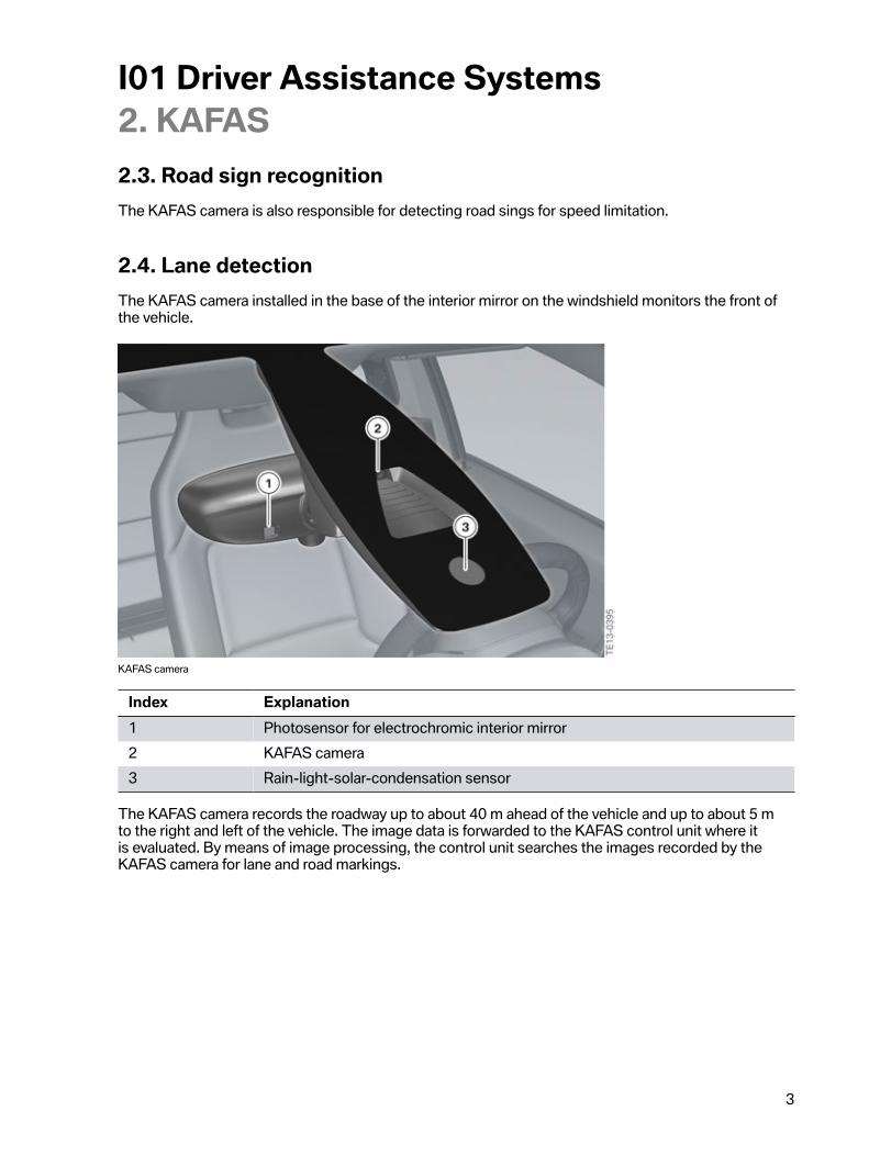
2.4.�Lane�detectionThe�KAFAS�camera�installed�in�the�base�of�the�interior�mirror�on�the�windshield�monitors�the�front�ofthe�vehicle.
KAFAS�camera
Index Explanation1 Photosensor�for�electrochromic�interior�mirror2 KAFAS�camera3 Rain‐light‐solar-condensation�sensor
The�KAFAS�camera�records�the�roadway�up�to�about�40 m�ahead�of�the�vehicle�and�up�to�about�5 mto�the�right�and�left�of�the�vehicle.�The�image�data�is�forwarded�to�the�KAFAS�control�unit�where�itis�evaluated.�By�means�of�image�processing,�the�control�unit�searches�the�images�recorded�by�theKAFAS�camera�for�lane�and�road�markings.

I01�Driver�Assistance�Systems2.�KAFAS
4
KAFAS�control�unit
The�image�data�acquired�by�the�KAFAS�camera�is�transferred�to�the�KAFAS�control�unit�via�a�LVDSdata�line.
Image�transmission�via�LVDS�data�line
Index Explanation1 KAFAS�control�unit2 KAFAS�camera
The�appearance�of�the�road�markings�and�signs�can�vary�considerably�in�the�image�depending�onthe�country,�type�of�road�or�the�current�ambient�conditions.�The�system�can�detect�a�wide�range�ofroad�markings�and�types�of�markings.�For�a�lane�marking�to�be�evaluated,�the�KAFAS�camera�and�theKAFAS�control�unit�must�first�be�able�to�clearly�identify�it.�For�a�lane�to�be�evaluated,�its�average�widthmust�be�greater�than�2.5 m.
The�KAFAS�camera�and�KAFAS�control�unit�are�the�most�important�elements�of�the�assist�systems�inthe�I01�as�these�are�extensively�camera�based.

I01�Driver�Assistance�Systems2.�KAFAS
5
2.5.�Functional�limitationsThe�function�of�the�KAFAS�camera�and�thus�also�the�function�of�the�corresponding�assist�systemsmay�be�impaired,�due�to�the�physical�limits�of�the�optical�systems�for�example,�in�the�followingsituations:
• heavy�fog,�rain�or�snow• bright�light�in�the�camera�lens• if�the�viewing�area�of�the�KAFAS�camera�or�the�windshield�is�dirty• on�tight�corners• up�to�10�seconds�after�driving�readiness�is�activated�via�the�START-STOP�button• during�the�calibration�process�of�the�KAFAS�camera�immediately�after�vehicle�delivery�or�a
camera�replacement.
Example�of�limits�of�the�KAFAS�camera
System�and�functional�limitations�mean�that�warnings�and�bans�may�under�certain�circumstances�notbe�issued�or�are�issued�too�late�or�without�authorization.�The�driver�must�therefore�always�remain�alertand�observant�so�that�they�can�actively�intervene�at�any�time�so�as�to�avoid�the�risk�of�an�accident.

I01�Driver�Assistance�Systems3.�Optional�Equipment�System
6
The�control�unit�for�the�optional�equipment�system�(SAS)�which�features�a�large�number�of�driverassistance�functions�is�being�used�for�the�first�time�in�the�I01.
Possible�functions:
• Camera-based�collision�warning• Collision�warning�with�city�braking�function• Pedestrian�warning�with�city�braking�function• Proactive�driving�assistant• Parking�maneuvering�assistant• Cruise�control�with�braking�function• Camera-based�cruise�control�with�Stop�&�Go�function
The�optional�equipment�system�(SAS)�is�not�part�of�the�standard�vehicle�equipment�and�is�installeddepending�on�which�optional�equipment�is�used.
Control�unit�for�optional�equipment�system�(SAS)
The�image�data�required�by�the�optional�system�(SAS)�is�made�available�by�the�KAFAS�control�unit.The�SAS�is�connected�to�the�FlexRay,�and�also�to�the�KAFAS�control�unit�via�a�Local-CAN.

I01�Driver�Assistance�Systems4.�Camera-based�Collision�Warning
7
The�camera-based�collision�warning�is�an�element�of�the�optional�equipment�ACC�Stop�&�Go�+�ActiveDriving�Assistant�(SA5AT).�The�collision�warning�warns�the�driver�of�a�possible�collision�danger�andis�effected�via�the�KAFAS�camera�and�KAFAS�control�unit.�The�camera-based�collision�warning�wasextended�in�the�BMW�I01�to�incorporate�the�functions�collision�warning�with�city�braking�function�andpedestrian�warning�with�city�braking�function.
The�system�warns�the�driver�in�situations�where�a�collision�is�imminent.�The�early�warning,�a�visualsignal,�is�issued�first�to�draw�the�driver's�attention�to�the�situation.�If�the�situation�becomes�morecritical,�an�acute�early�warning�in�the�form�of�a�visual�and�acoustic�signal�is�issued.�The�nature�of�thewarning�is�such�that�the�driver�can�still�prevent�a�collision�providing�he/she�acts�quickly.
4.1.�OperationThe�collision�warning�and�pedestrian�warning�functions�are�switched�on�automatically�when�thedriving�readiness�is�activated�via�the�START-STOP�button.
Switching�on/off
The�collision�warning�and�pedestrian�warning�are�switched�on�and�off�via�the�Intelligent�Safety�button.
Intelligent�Safety�button
Index Explanation1 Intelligent�Safety�button
Press�button:
• A�menu�is�displayed�in�the�Central�Information�Display�(CID).�The�collision�warning�andpedestrian�warning�functions�can�then�be�selectively�switched�on�and�off.�The�Personal�Profileis�stored�for�the�ID�transmitter�currently�used.

I01�Driver�Assistance�Systems4.�Camera-based�Collision�Warning
8
Intelligent�Safety:�all�systems�activated
Manual�adjustment�of�Intelligent�Safety:�pedestrian�warning�deactivated
Press�button�briefly:
• Intelligent�Safety�systems�are�switched�off�individually�depending�on�the�Personal�Profile• The�LED�in�the�Intelligent�Safety�button�lights�up�orange�or�goes�out,�depending�on�the
Personal�Profile
Press�button�again:
• All�Intelligent�Safety�systems�are�switched�on• The�LED�in�the�Intelligent�Safety�button�lights�up�green.
Press�and�hold�button:
• All�Intelligent�Safety�systems�are�switched�off• The�LED�in�the�Intelligent�Safety�button�goes�out.
Adjusting�the�warning�time
When�the�collision�warning�is�activated�the�driver�can�set�the�time�of�the�early�warning�in�three�stages.The�"late"�setting�corresponds�to�the�point�of�the�acute�warning.
The�setting�is�made�via�the�iDrive:

I01�Driver�Assistance�Systems4.�Camera-based�Collision�Warning
9
• "Settings"• "Collision�warning"• Set�the�required�warning�time�via�the�controller�at�the�Central�Information�Display.
The�setting�for�the�time�of�the�early�warning�is�saved�for�the�current�driver�profile�or�for�the�IDtransmitter�currently�used.
4.2.�Functional�principleThe�KAFAS�camera�records�the�scenery�ahead�of�the�vehicle�and�uses�image�processing�to�detect�thecomplete�rear�views�of�moving�and�stationary�vehicles�in�the�field�of�view.
Collision�warning�detection�range�by�KAFAS�video�camera
The�corresponding�warning�stages�"early�warning"�and�"acute�warning"�are�output�in�critical�situationson�the�basis�of�the�calculated�positions,�distances�and�relative�speeds�of�other�vehicles.�For�the�earlywarning�the�brakes�of�the�vehicle�are�prepared�for�emergency�braking�and�the�activation�thresholdsof�the�brake�assistants�are�reduced.�If�the�driver�makes�the�conscious�decision�to�drive�up�close�tothe�vehicle�ahead,�warnings�which�may�otherwise�be�distracting�can�be�prevented�by�reducing�thesensitivity�of�the�system.
Collision�warning�with�city�braking�function
The�collision�warning�with�city�braking�function�extends�the�camera-based�collision�warning�with�abraking�function�from�a�speed�of�roughly�10 km/h�/�6�mph�up�to�a�maximum�speed�of�60 km/h�/�37mph.�If�an�acute�warning�is�issued�within�this�speed�range,�the�vehicle�is�decelerated�by�4 m/s²�at�themost.
The�brake�intervention�is�restricted�to�roughly�1.6�seconds.�This�avoids�additional�dangers�for�thefollowing�traffic.

I01�Driver�Assistance�Systems4.�Camera-based�Collision�Warning
10
Example�of�vehicle�identification�by�KAFAS�camera
Index Explanation1 Vehicle�in�same�lane2 Vehicle�in�different�lane
Pedestrian�warning�with�city�braking�function
The�system�provides�a�warning�against�a�collision�with�pedestrians�from�a�speed�of�roughly�10 km/h�/�6mph�up�to�a�maximum�speed�of�60 km/h�/�37�mph�.
The�KAFAS�camera�records�the�scenery�ahead�of�the�vehicle�and�uses�image�processing�to�detectpedestrians�in�the�field�of�view.�An�acute�warning�is�output�in�critical�situations�on�the�basis�of�thecalculated�positions,�distances�and�the�movement�of�the�identified�pedestrians.�An�early�warning�isnot�available�for�the�pedestrian�warning�with�city�braking�function.�With�an�acute�warning�the�vehicle�isdecelerated�by�roughly�4 m/s².
Example�of�person�recognition�by�KAFAS�camera
The�warning�zone�for�person�recognition�in�front�of�the�vehicle�is�subdivided�into�two�areas.�Thecentral�area�(ahead�of�the�vehicle)�and�the�additional�area�(to�the�left�and�right�in�front�of�the�vehicle).

I01�Driver�Assistance�Systems4.�Camera-based�Collision�Warning
11
Warning�zone,�person�recognition
Index Explanation1 Central�area2 Extended�area
4.3.�Warning�functionThe�warning�function�is�divided�into�two�stages.�If�there�is�a�danger�of�collision,�a�warning�symbol�isdisplayed�at�the�instrument�cluster.
Display
Early�warning:
• Vehicle�symbol�lights�up�red• Text�message:�Increase�distance�and,�if
necessary,�brake.
Acute�warning:
• Vehicle�symbol�flashes�red�and�a�signalsounds
• Text�message:�Request�for�interventionby�braking�and,�if�required,�evasiveaction.

I01�Driver�Assistance�Systems4.�Camera-based�Collision�Warning
12
Acute�warning:
• Person�symbol�flashes�red�and�a�signalsounds
• Text�message:�Request�for�interventionby�braking�and,�if�required,�evasiveaction.
Early�warning
The�early�warning�is�issued,�for�example,�if�there�is�a�danger�of�collision�because�the�vehicle�drivingahead�is�being�driven�at�a�much�slower�speed�and/or�if�the�distance�to�a�driven�or�stationary�vehicleahead�is�extremely�short.
The�early�warning�is�indicated�by�a�vehicle�symbol�which�lights�up�red�in�the�instrument�cluster.
The�time�of�the�early�warning�can�be�configured�in�the�CID.
The�collision�warning�is�dependent�on�the�vehicle's�inherent�driving�speed.�The�distance�calculated�forthe�collision�warning�is�much�lower�than�the�minimum�distance�required�by�law.�It�is�therefore�still�thedriver's�responsibility�to�maintain�the�legal�minimum�distance.
Acute�warning
The�acute�warning�is�issued�by�the�system�as�late�as�possible�and�only�if�there�is�an�imminent�dangerof�a�collision�when�the�vehicle�is�approaching�the�vehicle�driving�ahead�at�a�relatively�high�differentialspeed�or�if�there�is�an�imminent�danger�of�a�collision�with�a�pedestrian.�The�point�at�which�the�acutewarning�is�issued�is�calculated�in�such�a�way�that�a�collision�can�only�be�avoided�by�immediateemergency�braking�or�by�an�evasive�manoeuvre.�The�acute�warning�therefore�cannot�be�deliberatelybrought�about�or�monitored�by�the�driver.
If�the�vehicle�is�for�example�approaching�the�vehicle�driving�ahead�at�very�low�speed,�or�is�approachinga�person,�an�acute�warning�is�not�issued�even�when�the�distance�is�very�small.�This�deliberatelybrought-about�driving�situation�merely�triggers�off�the�early�warning.�In�this�way,�less�sensible�and�thusmore�annoying�acute�warnings�are�avoided�by�the�system.
The�acute�warning�cannot�be�deactivated.�The�timing�of�the�acute�warning�also�cannot�be�adjusted.If�the�acute�warning�is�not�to�be�issued,�the�"collision�warning"�front�protective�function�must�bedeactivated.
The�acute�warning�issues�a�prompt�for�intervention�and�is�supported�if�there�is�a�danger�of�collisionby�a�two-stage�intervention.�Once�the�driver�has�been�warned�of�the�danger�of�collision,�brakepreconditioning�initially�takes�place�followed�by�the�initiation�of�automatic�brake�intervention�to�avertthe�collision�danger.
The�brake�intervention�is�restricted�to�roughly�1.6�seconds.�This�avoids�additional�dangers�for�thefollowing�traffic.
Once�the�target�object�has�been�verified�by�the�camera�data�braking�intervention�takes�place�atroughly�4 m/s².�This�achieves�a�speed�reduction�of�up�to�approx.�16 km/h.�In�the�bottom�speed�rangebraking�up�to�a�standstill�is�therefore�entirely�possible.

I01�Driver�Assistance�Systems4.�Camera-based�Collision�Warning
13
In�the�speed�range�of�10 km/h�/�6�mph�to�60 km/h�/�37�mph�,�brake�intervention�is�applied�at�a�brakeforce�of�roughly�4 m/s²�when�collision�with�a�pedestrian�is�detected.
Brake�intervention�also�takes�place�if�the�driver�fails�to�press�the�brake�pedal�sufficiently.
Brake�intervention�is�applied�only�when�Dynamic�Stability�Control�(DSC)�is�switched�on.
In�the�event�of�an�acute�warning,�a�red�flashing�vehicle�symbol�or�a�red�flashing�person�symbol�isdisplayed�for�the�driver�at�the�instrument�cluster.�In�addition,�an�acoustic�warning�signal�is�sounded.
The�acute�warning�does�not�relieve�the�driver�of�their�responsibility�to�adapt�their�driving�speed�anddriving�style�to�the�road�and�traffic�conditions�and�to�maintain�the�prescribed�safety�distance.
Brake�intervention�can�be�cancelled�by�pressing�the�accelerator�pedal�or�by�applying�a�clear�steeringwheel�movement.
The�braking�function�is�deactivated�when�Dynamic�Stability�Control�(DSC)�or�Dynamic�Traction�Control(DTC)�is�deactivated.
Chronological�sequence
The�timescale�of�the�warnings�and�the�braking�is�shown�in�the�following�graphic.�There�is�no�brakeintervention�if�an�avoidance�by�the�driver�is�recognized.
Timescale�of�camera-based�collision�warning

I01�Driver�Assistance�Systems4.�Camera-based�Collision�Warning
14
Index Explanation1 Collision�warning�(early)2 Collision�warning�(late)3 Acute�warning�(acoustic�warning�signal,�brake�system�is�prepared�and�brake
assistant�is�adapted)4 Braking�at�roughly�4 m/s²�is�introduced�(city�braking�function�only�in�the
approximate�range�of�roughly�10�to�60 km/h,�6�to�37�mph5 Detection�range�of�KAFAS�camera
4.4.�System�limitsRange�of�detection
The�collision�warning�has�a�limited�capacity�for�detection.�This�means�that�warnings�sometime�maynot�be�issued�or�may�be�issued�late.
The�following�vehicles�may�possibly�not�be�detected:
• A�vehicle�traveling�at�slow�speed�when�approaching�at�high�speed• Vehicles�that�cut�in�suddenly�or�are�heavily�decelerating• Vehicles�with�an�unusual�rear�view�or�with�poorly�visible�rear�lights• Partially�concealed�vehicles• Two-wheeled�vehicles�traveling�ahead.
Functional�limitations
The�function�of�the�KAFAS�camera�and�thus�also�the�function�of�the�corresponding�assist�systemsmay�be�impaired�in�the�following�situations,�for�example:
• heavy�fog,�rain�or�snow• insufficient�daylight• bright�light�in�the�camera�lens• if�the�viewing�area�of�the�KAFAS�video�camera�or�the�windshield�is�dirty• on�sharp�curves• with�persons�up�to�approx.�80 cm�in�height.• up�to�10�seconds�after�an�engine�start�via�the�START-STOP�button• during�the�calibration�process�of�the�KAFAS�video�camera�immediately�after�vehicle�delivery�or
a�camera�replacement.

I01�Driver�Assistance�Systems4.�Camera-based�Collision�Warning
15
System�limitations�mean�that�warnings�may�under�certain�circumstances�not�be�issued�or�are�issuedtoo�late�or�without�authorisation.�The�driver�must�therefore�always�remain�alert�and�observant�so�thatthey�can�actively�intervene�at�any�time�so�as�to�avoid�the�risk�of�an�accident.

I01�Driver�Assistance�Systems4.�Camera-based�Collision�Warning
16
4.5.�System�wiring�diagram
System�wiring�diagram�for�camera-based�collision�warning

I01�Driver�Assistance�Systems4.�Camera-based�Collision�Warning
17
Index Explanation1 Heating�KAFAS�camera2 KAFAS�camera3 Dynamic�Stability�Control4 Fuse5 Body�Domain�Controller6 Fuse7 Optional�equipment�system�(SAS)8 Intelligent�Safety�button9 Steering�column�switch�cluster10 Instrument�cluster11 KAFAS�control�unit

I01�Driver�Assistance�Systems5.�Road�Sign�Recognition
18
The�road�sign�recognition�displays�a�road�sign�symbol�in�the�instrument�cluster�which�shows�themaximum�speed�limit�currently�detected.�The�KAFAS�camera�detects�road�signs�at�the�edge�of�theroad.�The�optional�equipment�road�sign�recognition�is�an�element�of�the�optional�equipment�ACC�Stop&�Go�+�Active�Driving�Assistant�(SA�5AT).
Responsibility�for�the�vehicle�and�for�the�speed�that�is�adopted�rests�exclusively�with�the�driver.
5.1.�OperationThe�road�sign�recognition�can�be�switched�on�and�off�in�the�iDrive�menu�by�making�the�followingselection�via�the�controller:
• Settings• KOMBI• Speed�Limit�Info
If�the�road�sign�recognition�is�switched�on,�this�is�displayed�at�the�KOMBI�in�the�instrument�cluster.�Ifa�speed�limit�symbol�with�three�horizontal�dashes�is�displayed�in�the�instrument�cluster�instead�of�themax.�permissible�speed,�the�road�sign�recognition�is�not�available.
5.2.�System�limitsThe�system�has�a�detection�rate�of�around�90�to�95 %.
Traffic�signs�for�top�speed�limitations�that�do�not�comply�with�the�legal�standard,�particularly�thosewithout�square�frames,�are�not�always�detected.�The�same�applies�to�road�signs�which�are�fully�orpartially�concealed�by�stickers,�dirt�or�vegetation.�Long�distances�to�the�road�sign,�high�driving�speedsand�poor�weather�conditions,�particularly�at�night,�make�it�more�difficult�for�the�system�to�recognizeroad�signs�reliably.�To�ensure�the�current�top�speed�limitations�are�displayed�as�accurately�as�possible,the�data�of�the�navigation�road�map�should�be�up-to-date.
The�functionality�of�the�road�sign�display�may�be�limited,�e.g.�in�the�following�situations,�which�can�leadto�an�incorrect�display:
• heavy�fog,�rain�or�snow• if�signs�are�covered�by�objects• if�driving�at�close�proximity�to�a�vehicle�driving�ahead• strong�light�in�the�camera�lens• if�the�windshield�in�front�of�the�interior�mirror�is�fogged,�dirty�or�covered�by�labels,�etc.• as�a�result�of�incorrect�detection�by�the�camera• if�the�top�speed�limitations�stored�in�the�navigation�system�are�incorrect• in�areas�not�covered�by�the�navigation�system

I01�Driver�Assistance�Systems5.�Road�Sign�Recognition
19
• in�the�event�of�deviations�from�the�navigation,�e.g.�due�to�modified�road�layouts• if�traffic�signs�do�not�correspond�to�the�standard• when�calibrating�the�camera�immediately�after�vehicle�delivery.
Supplementary�sign�recognition
The�system�can�only�recognize�supplementary�signs�with�pictograms�(icons),�such�as�e.g.�"In�wetconditions",�"In�rain/snow�conditions",�"Trucks"�or�"Trailers".�Text�references�to�supplementary�signsbasically�cannot�be�read�or�interpreted.
Before�top�speed�limitations�with�a�limited�applicability�are�displayed,�the�system�checks�the�vehicleelectrical�system�for�more�information.�Thus,�with�the�validity�"In�wet�conditions"�the�status�of�thewindscreen�wiper�is�evaluated�or�with�the�validity�"In�frost/snow�conditions"�the�temperature�valuefrom�the�outside�temperature�sensor�is�evaluated.
The�time�limits�of�the�top�speed�limitation�can�then�only�be�evaluated�correctly�if�the�period�of�validityis�stored�in�the�navigation�map�and�the�clock�in�the�vehicle�is�set�correctly.�Otherwise�the�top�speedlimitation�or�ban�on�passing/overtaking�is�displayed�as�currently�valid.
The�trailer�signal�for�vehicles�in�towing�mode�is�not�evaluated�for�the�display�of�top�speed�limitations,as�they�differ�from�country�to�country�and�depend�on�the�trailer�type.
Other�supplementary�road�signs�are�not�recognized.�The�top�speed�limitation�is�then�displayed�as�validand�up-to-date�without�the�interpretation�of�the�supplementary�road�sign.
Road�signs�on�parallel,�branching-off�or�merging�roads�and�on�exits
Parallel�roads�are�recognized�neither�with�the�KAFAS�camera�nor�with�the�aid�of�the�navigation�map.Signs�erected�there�could�be�incorrectly�recognized�and�displayed�as�top�speed�limitation�for�the�roadcurrently�being�driven�on.
Top�speed�limitations�for�branching-off�or�merging�roads�are�usually�also�adopted�and�displayed�forthe�road�currently�being�driven�on.
Top�speed�limitations�on�motorway�exits�with�or�without�an�additional�arrow�sign�are�usually�correctlyevaluated�and�suppressed�in�the�display�when�the�exit�is�passed�providing�the�navigation�map�data�isup-to-date.
In�the�case�of�overhead�motorway�signs�with�different,�lane-specific�top�speed�limitations,�the�topspeed�limitation�nearest�to�the�lane�in�which�the�vehicle�is�driving�in�is�displayed.�The�display�is�notmodified�after�a�later�lane�change.
Information�signs�in�the�road�sign�surroundings
Information�signs�with�top�speed�limitations,�e.g.�at�border�crossings�with�references�to�the�differentlegal�maximum�speeds�for�ordinary�roads�and�highways,�can�be�mistakenly�recognized�as�currentlyvalid�and�displayed.�The�same�applies�to�information�signs�with�different�color�configurations,�e.g.�forminimum�or�recommended�speeds.
Stickers�on�vehicles
Stickers�on�vehicles�driving�ahead�or�overtaken�vehicles�indicating�a�top�speed�limitation,�e.g.�trucks,buses,�trailers�and�construction�machinery,�could�be�mistakenly�recognized�and�displayed�as�thecurrently�valid�top�speed�limitation.

I01�Driver�Assistance�Systems5.�Road�Sign�Recognition
20
Town/city�limits
If�the�town/city�limits�sign�is�not�clearly�recognized�and�the�data�in�the�navigation�map�is�not�up-to-date,�the�top�speed�limitation�at�town/city�limits�may�be�incorrectly�displayed.
Legal�changes
If�maximum�speeds�prescribed�by�law�are�changed,�these�are�only�available�after�a�software�update.The�original�speed�limits�which�no�longer�apply�continue�to�be�displayed�until�the�software�is�updated.
The�system�cannot�replace�the�driver's�personal�assessment�of�the�road�and�traffic�situation.�Systemand�functional�limitations�mean�that�warnings�and�bans�may�under�certain�circumstances�not�beissued�or�are�issued�too�late�or�without�authorisation.�Road�sign�recognition�supports�the�driver�anddoes�not�replace�the�human�eye.

I01�Driver�Assistance�Systems6.�Proactive�Driving�Assistant
21
This�proactive�driving�assistant�detects�bends,�entrances�to�towns,�roundabouts,�intersections,junctions,�speed�limits�and�highway�exits�using�the�data�from�the�navigation�system�and�can�suggestat�an�early�stage�that�the�driver�should�take�his�foot�off�the�accelerator�pedal.�A�message�is�also�issuedif�the�section�of�road�ahead�has�not�yet�been�detected.�This�information�is�displayed�in�the�instrumentcluster�until�the�road�section�is�reached.�The�proactive�driving�assistant�helps�drivers�who�are�notfamiliar�with�the�route�or�area�to�drive�more�efficiently.
Display�in�the�instrument�cluster
Proactive�driving�assistant�symbol
6.1.�OperationTo�use�the�proactive�driving�assistant,�ECO�PRO�mode�or�ECO�PRO+�mode�must�be�activated�via�thedriving�experience�switch.
Switch�block�with�driving�experience�switch
Index Explanation1 Driving�experience�switch
The�proactive�driving�assistant�can�be�used�when�the�route�guidance�is�active�and�inactive.�When�theroute�guidance�is�not�active,�the�most�likely�route�is�used�for�evaluation.�However,�the�calculation�canbe�performed�more�accurately,�and�therefore�more�efficiently,�when�the�route�guidance�is�active.

I01�Driver�Assistance�Systems6.�Proactive�Driving�Assistant
22
The�reliability�of�the�system�depends�on�the�version�and�quality�of�the�navigation�data.
6.2.�System�limitsThe�proactive�driving�assistant�is�not�available�in�the�following�situations:
• Speed�below�50�kph�/�31�mph• Temporary�and�variable�top�speed�limitation,�e.g.�on�construction�sites• Quality�of�navigation�data• Cruise�control�active.

I01�Driver�Assistance�Systems7.�Reversing�Camera
23
The�rear�view�camera�is�only�available�in�conjunction�with�the�parking�assistance�package�(SA�5DU)included�in�the�Parking�Package�ZPK�and�provides�the�driver�with�additional�support�when�entering/exiting�parking�spaces�and�when�maneuvering.
Rear�view�camera,�view�in�CID
The�image�from�the�reversing�camera�is�displayed�with�additional�extension�lines�in�the�CentralInformation�Display.�The�display�help�lines�function�can�be�switched�on�and�off�by�the�driver�via�thecontroller.
Rear�view�camera,�view�in�CID,�setting�parking�assistance�lines
Rear�view�camera,�view�in�CID�with�parking�assistance�lines
The�obstruction�marking�provides�the�driver�with�further�assistance.�This�can�also�be�switched�on�andoff�in�iDrive.

I01�Driver�Assistance�Systems7.�Reversing�Camera
24
Rear�view�camera,�view�in�CID,�setting�obstruction�marking
Rear�view�camera,�view�in�CID�with�parking�assistance�lines�and�obstruction�marking
7.1.�System�componentsThe�control�unit�for�the�Top�Rear�Side�View�Camera�(TRSVC�control�unit)�is�integrated�into�the�housingof�the�rear�view�camera.�Side�View�and�Top�View�cameras�are�not�available�with�the�I01.
Control�unit�of�rear�view�camera
The�new�camera�must�be�taught�in�after�the�reversing�camera�is�replaced.�The�reversing�camera�of�theI01�does�not�need�to�be�calibrated�after�teaching-in,�as�it�is�self-calibrating.�The�calibration�is�carriedout�during�driving�by�the�TRSVC�control�unit�by�means�of�a�steering�angle�sensor�and�known�roadmarkings.�Installation�tolerances�are�done�by�shifting�and�rotating�the�image�during�calibration.�Themaximum�time�required�for�a�full�calibration�is�five�hours.�A�Check�Control�message�is�displayed�in�the

I01�Driver�Assistance�Systems7.�Reversing�Camera
25
CID�if�the�reversing�camera�could�not�be�successfully�calibrated.�Reasons�for�failed�calibration�may�beincorrect�installation,�dirt�contamination�or�a�defect�with�the�reversing�camera.�The�reversing�camera�isalso�constantly�readjusted�after�a�full�calibration�in�order�to�ensure�an�optimum�image.
The�opening�angle�of�the�reversing�camera's�lens�is�130°.

I01�Driver�Assistance�Systems7.�Reversing�Camera
26
7.2.�System�wiring�diagram
System�wiring�diagram,�reversing�camera

I01�Driver�Assistance�Systems7.�Reversing�Camera
27
Index Explanation1 Central�information�display2 Body�Domain�Controller3 CAN-Terminator4 Fuse5 Rear�view�camera�with�integrated�TRSVC�control�unit6 Head�unit7 Controller

I01�Driver�Assistance�Systems8.�Park�Distance�Control
28
Park�Distance�Control�(PDC)�assists�the�driver�when�maneuvering�in�and�out�of�a�parking�space.
The�front�and�rear�Park�Distance�Control�(SA�508)�is�included�in�the�optional�Parking�Package�(ZPK)�inthe�I01.�.
The�distance�between�the�vehicle�and�obstacle�is�measured�by�four�ultrasonic�sensors�in�the�rearbumper�and,�in�vehicles�with�Park�Distance�Control,�four�additional�ultrasonic�sensors�are�alsoincorporated�into�the�front�bumper.
8.1.�System�componentsThe�PMA�control�unit�is�used�instead�of�the�PDC�control�unit�in�vehicles�with�the�optional�equipmentParking�Maneuvering�Assistant.�The�PMA�control�unit�is�exactly�the�same�dimensions�and�installationposition�as�the�PDC�control�unit.�Compared�to�the�PDC�control�unit,�the�PMA�control�unit�has�a�morepowerful�processor�and�software.
Park�Distance�Control�system�components

I01�Driver�Assistance�Systems8.�Park�Distance�Control
29
Index Explanation1 Front�ultrasonic�sensors,�only�installed�with�optional�equipment�Parking
Package�(SA�ZPK)2 Parking�Maneuvering�Assistant�ultrasonic�sensors,�only�installed�with�optional
equipment�Parking�Package�(SA�ZPK)3 Operating�facility4 Park�Distance�Control�control�unit5 Ultrasonic�sensors,�rear

I01�Driver�Assistance�Systems8.�Park�Distance�Control
30
8.2.�System�wiring�diagram
Park�Distance�Control�system�wiring�diagram

I01�Driver�Assistance�Systems8.�Park�Distance�Control
31
Index Explanation1 Ultrasonic�sensors,�Park�Distance�Control,�front2 Fuse3 Park�Distance�Control�control�unit4 Ultrasonic�sensors,�Park�Distance�Control,�rear5 Vehicle�speaker6 Head�unit7 Operating�facility8 Body�Domain�Controller9 Central�information�display
8.3.�OperationThe�Park�Distance�Control�system�is�enabled�in�the�following�situations:
• if�drive�position�R�is�engaged�when�driving�readiness�is�switched�on• if�the�parking�assistance�button�in�the�switch�block�next�to�the�iDrive�is�pressed�when�driving
readiness�is�switched�on• the�activation�takes�place�automatically�if�the�vehicle�is�equipped�with�the�optional�equipment
Parking�Package�(SA�ZPK)�and�obstacles�behind�or�in�front�of�the�vehicle�are�detected�by�thePark�Distance�Control�and�the�vehicle�is�traveling�at�less�than�approx.�3 km/h�/�1�mph.
Switch�block�with�parking�assistance�button
Index Explanation1 Parking�assistance�button

I01�Driver�Assistance�Systems8.�Park�Distance�Control
32
With�Park�Distance�Control�system�(SA�508)�which�is�included�in�the�optional�Parking�Package�ZPK,activation�only�takes�place�when�the�drive�position�"R"�is�engaged.�A�parking�assistance�button�is�notinstalled�with�this�configuration.
The�automatic�activation�of�the�PDC�system�is�implemented�in�combination�with�the�optionalequipment�Parking�Package�(SA�ZPK).�The�automatic�activation�which�takes�place�when�obstacles�aredetected�can�be�switched�on�and�off�via�the�controller�in�the�"Settings"�menu.�The�settings�are�storedfor�the�ID�transmitter�which�is�currently�being�used.
Automatic�Park�Distance�Control
Automatic�activation�of�the�PDC�system�by�the�Auto�PDC�is�only�possible�within�a�speed�range�of�lessthan�3 km/h.
If�Auto�PDC�was�active�and�was�switched�off�via�the�PDC�button,�the�speed�threshold�of�5 km/h�/�3mph�must�have�been�exceeded�once�for�the�Auto�PDC�to�be�operational�once�again.
The�driver�is�notified�about�the�results�of�the�distance�measurements�and�the�distance�warningsacoustically�via�the�audio�speakers�and�optically�via�the�Central�Information�Display�CID.�As�the�vehicleapproaches�an�object,�the�corresponding�position�is�indicated�by�an�intermittent�tone�via�the�audiospeaker.�If,�for�example,�an�object�is�detected�behind�the�vehicle�to�the�left,�the�rear�left�speaker�emitsan�acoustic�signal.�A�continuous�alarm�sounds�when�the�object�is�at�a�distance�of�about�25 cm�or�less.The�volume�of�the�acoustic�signal�of�the�Park�Distance�Control�system�can�be�adjusted�in�relation�tothe�audio�playback�of�the�entertainment�system.
Park�Distance�Control�volume�balancing
Deactivation�criteria
I01�Driver�Assistance�Systems8.�Park�Distance�Control
33
Similar�to�other�BMW�models,�the�deactivation�is�distance/speed�based.�It�is�switched�off�after�drivingof�about�50 m�or�at�speeds�in�excess�of�36 km/h�/�22�mph.
If�a�fault�develops,�a�Check�Control�message�("PDC�has�malfunctioned.�Have�system�checked.")�isdisplayed�in�the�Central�Information�Display�CID.�In�addition,�the�detection�range�of�the�sensors�isshown�shaded�in�the�Central�Information�Display�CID.
8.4.�System�limitsDue�to�the�physical�limits�during�the�ultrasonic�measurement,�obstructions�may�not�be�detected�by�thePark�Distance�Control�system.�Several�examples�of�this�are�shown�below:
• when�the�objects�are�thin�or�wedge-shaped• when�the�objects�are�low• when�objects�that,�due�to�their�shape,�have�corners�and�sharp�edges• with�snow• if�the�objects�have�a�porous�surface.
A�warning�may�also�be�displayed�although�there�is�no�obstruction�in�the�detection�range;�in�thefollowing�situations�for�example:
• when�it�is�raining�heavily• if�the�sensors�are�heavily�soiled�or�iced�over• if�the�sensors�are�covered�with�snow• if�the�street�surface�is�rough• if�the�road�surface�is�bumpy,�e.g.�speed�bumps• due�to�heavy�exhaust�gas�fumes• due�to�other�ultrasound�sources.
To�ensure�the�ultrasonic�sensors�remain�fully�operational,�they�must�be�kept�clean�and�free�of�ice.When�cleaning�the�sensors�using�a�high�pressure�cleaner,�avoid�direct�and�sustained�contact�with�ahigh-pressure�water�jet.�Furthermore,�when�using�high�pressure�cleaners,�a�distance�of�at�least�30 cmfrom�the�sensors�must�be�maintained.
The�Park�Distance�Control�cannot�replace�the�driver's�personal�judgement�of�the�traffic�situation.�Alsocheck�the�traffic�situation�by�taking�a�look�around�the�vehicle.�Otherwise�there�is�a�risk�of�accidentsoccurring,�due�to�other�road�users�or�objects�that�are�outside�the�detection�range�of�the�Park�DistanceControl�for�example.�Loud�sound�sources�outside�and�inside�the�vehicle�could�drown�out�the�PDCsignal.

I01�Driver�Assistance�Systems9.�Parking�Maneuvering�Assistant
34
The�Parking�Maneuvering�Assistant�(PMA)�supports�the�driver�in�many�ways.�The�assistant�measuresthe�size�of�a�gap�between�cars�and�decides�based�on�the�result�whether�the�gap�is�large�enough�on�theone�hand�and�relieves�the�driver�of�the�task�of�maneuvering�into�the�space�on�the�other.�The�ParkingManeuvering�Assistant�(SA�5DP)�is�used�in�the�I01�as�optional�equipment�and�can�only�be�ordered�inconjunction�with�the�Parking�Package�(SA�ZPK).
The�Parking�Maneuvering�Assistant�(PMA)�has�one�additional�function�with�the�BMW�I01.�In�theI01�the�Parking�Maneuvering�Assistant�(PMA)�can�now�in�addition�to�steering�also�perform�theacceleration,�braking�and�gear�changing�when�parking�parallel�to�and�at�the�side�of�the�road.
Principle�of�Parking�Maneuvering�Assistant

I01�Driver�Assistance�Systems9.�Parking�Maneuvering�Assistant
35
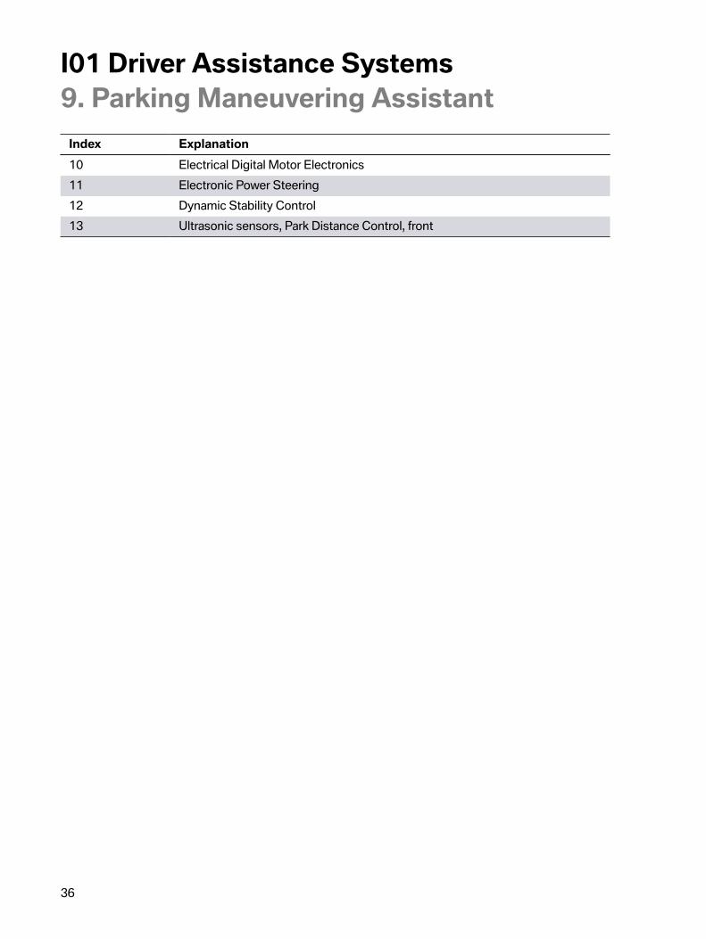
9.1.�System�components
System�components�of�Parking�Maneuvering�Assistant
Index Explanation1 Ultrasonic�sensors�of�Parking�Maneuvering�Assistant2 Body�Domain�Controller3 Central�information�display4 Controller5 Parking�Maneuvering�Assistant�control�unit6 Head�unit7 Optional�equipment�system�(SAS)8 Ultrasonic�sensors,�Park�Distance�Control,�rear9 Operating�facility,�parking�assistance�button�(switch�block�in�center�console)
I01�Driver�Assistance�Systems9.�Parking�Maneuvering�Assistant
36
Index Explanation10 Electrical�Digital�Motor�Electronics11 Electronic�Power�Steering12 Dynamic�Stability�Control13 Ultrasonic�sensors,�Park�Distance�Control,�front

I01�Driver�Assistance�Systems9.�Parking�Maneuvering�Assistant
37
9.2.�System�wiring�diagram
System�wiring�diagram�for�Parking�Maneuvering�Assistant

I01�Driver�Assistance�Systems9.�Parking�Maneuvering�Assistant
38
Index Explanation1 Ultrasonic�sensor,�Parking�Maneuvering�Assistant�left2 Ultrasonic�sensors,�Park�Distance�Control,�front3 Ultrasonic�sensor,�Parking�Maneuvering�Assistant�right4 Dynamic�Stability�Control5 Fuse6 Parking�Maneuvering�Assistant�control�unit7 Ultrasonic�sensors,�Park�Distance�Control,�rear8 Vehicle�speaker9 Head�unit10 Operating�unit,�parking�assistance�button11 Body�Domain�Controller12 Controller13 Central�information�display14 Electrical�Digital�Motor�Electronics15 Electromechanical�Power�Steering
9.3.�Sensors
Installation�location,�ultrasonic�sensors�of�Parking�Maneuvering�Assistant
The�gaps�between�cars�are�measured�via�two�additional�ultrasonic�sensors�which�are�integrated�intothe�front�wheel�arch.�These�two�sensors�are�connected�to�the�control�unit�of�the�Parking�ManeuveringAssistant�(PMA)�which�also�incorporates�the�PDC�function.�The�function�of�the�two�ultrasonic�sensorsis�similar�to�that�of�the�PDC.�Ultrasonic�pulses�are�transmitted�and�echo�signals�are�received.

I01�Driver�Assistance�Systems9.�Parking�Maneuvering�Assistant
39
9.4.�Control�unit
Installation�location,�control�unit�of�Parking�Maneuvering�Assistant
The�Parking�Maneuvering�Assistant�(PMA)�control�unit�evaluates�the�signals�from�the�ultrasonicsensors�and�calculates�the�length�and�width�of�a�gap�between�cars�using�the�distance�informationfrom�the�Dynamic�Stability�Control.�Furthermore,�it�evaluates�the�signals�from�the�sensors�and�thusidentifies�possible�parking�spaces.�It�also�calculates�the�optimum�path�into�a�parking�space,�monitorsthe�parking�process�and�controls�the�electromechanical�steering.
The�main�unit�of�the�function�is�integrated�into�the�SAS,�from�where�the�longitudinal�control,�thedisplays�in�the�headunit,�the�brake�and�electric�motor�are�activated,�and�the�lateral�guidance�in�thePMA�is�enabled.
Control�unit�optional�equipment�system�(SAS)

I01�Driver�Assistance�Systems9.�Parking�Maneuvering�Assistant
40
9.5.�Functional�principleThe�Parking�Maneuvering�Assistant�facilitates�parking�in�gaps�between�cars�parallel�to�the�roadway.When�driving�forwards�straight�ahead�up�to�speeds�of�roughly�35 km/h�/�22�mph,�parking�spaces�aremeasured�irrespective�of�whether�the�Parking�Maneuvering�Assistant�is�activated�or�deactivated.If�a�gap�that�is�the�same�length�as�the�vehicle�plus�approx.�1.2 m�has�been�found�and�if�the�systemis�already�activated,�this�gap�is�displayed�to�the�driver.�The�ultrasonic�sensors�of�the�PMA�measureparking�spaces�on�both�sides�of�the�vehicle�and�parking�spaces�that�have�been�detected�are�displayedto�the�driver�in�the�CID.
Measurement�of�the�gap
The�PMA�calculates�the�optimum�parking�line�and�subsequently�undertakes�the�complete�vehicleguidance�with�steering,�braking�and�changing�drive�position.�Gear�P�is�engaged�at�the�end�of�theparking�operation.
The�driver�is�still�responsible�for�monitoring�the�vehicle�environment�and�can�intervene�in�theautomatic�parking�manoeuvre�at�any�time�if�required�due�to�the�vehicle�environment.�Whensearching�for�a�parking�space�and�when�parking,�all�relevant�information�is�presented�to�the�driverin�an�integrated�display;�from�the�parking�space�itself�to�the�status�of�the�parking�assistant�andcorresponding�handling�instructions�through�to�distances�from�other�objects.
Personal�responsibility:
• Directly�monitor�the�parking�space�and�parking�procedure�and�intervene�if�necessary,�asotherwise�an�accident�may�occur
• If�a�parking�space�that�has�already�been�measured�changes,�the�system�does�not�take�this�intoaccount
• The�system�does�not�take�loads�that�project�beyond�the�vehicle�into�account�during�parking• The�PMA�may�steer�the�vehicle�over�or�up�onto�curbs.�You�should�therefore�use�the�facility�for
active�intervention�at�any�time�with�caution�as�you�may�otherwise�damage�wheels�and�tires�orthe�vehicle�itself.
The�Parking�Maneuvering�Assistant�(PMA)�does�not�relieve�the�driver�of�personal�responsibilityduring�parking.�The�driver�must�therefore�always�remain�alert�and�observant�so�that�they�can�activelyintervene�at�any�time�so�as�to�avoid�the�risk�of�an�accident.

I01�Driver�Assistance�Systems9.�Parking�Maneuvering�Assistant
41
9.6.�Functional�prerequisitesMeasuring�parking�spaces
• Driving�forwards�straight-ahead�up�to�approx.�35 km/h�/�22�mph• Maximum�distance�to�the�row�of�parked�vehicles:�1.5 m
Suitable�parking�spaces
• Minimum�length�of�space:�own�vehicle�length�plus�approx.�1.2�m• Minimum�depth:�approx.�1.5 m.
Parking�procedure
• Closed�doors• Automatic�Hold�brake�released• The�corresponding�turn�indicator�must�be�on�when�parking�.
9.7.�OperationIn�principle�there�are�two�ways�to�activate�the�Parking�Maneuvering�Assistant:
Activation�via�parking�assistance�button
When�the�PMA�is�activated�via�the�parking�assistance�button�in�the�center�console�the�parkingassistance�menu�in�the�CID�is�displayed.�As�soon�as�a�parking�space�is�found,�the�driver�receiveshandling�instructions�that�guide�him�though�the�parking�procedure�with�the�support�of�the�system.When�parking�automatically,�the�driver�must�press�the�parking�assistance�button�until�the�parkingprocedure�is�complete.
Switch�block�with�parking�assistance�button

I01�Driver�Assistance�Systems9.�Parking�Maneuvering�Assistant
42
Index Explanation1 Parking�assistance�button
Activation�by�"Engaging�reverse�gear"�followed�by�"iDrive�controller�operation"
When�the�reverse�gear�is�engaged,�the�parking�assistance�menu�is�displayed�in�the�CID�accompaniedby�the�status�of�the�parking�space�search.�The�PMA�is�however�not�yet�activated.�This�is�indicated�bythe�PMA�symbol�in�the�symbol�bar�of�the�CID.�In�order�to�park�supported�by�the�system,�the�parkingoperation�must�be�activated�via�the�controller�by�selecting�the�corresponding�symbol�in�the�symbol�barat�the�CID.�When�parking�automatically,�the�driver�must�press�the�parking�assistance�button�until�theparking�procedure�is�complete.
Park�procedure
A�checkmark�then�appears�on�the�right�below�the�PMA�symbol�in�the�CID�to�tell�the�driver�that�thePMA�is�active.
Parking�procedure�via�PMA
If�the�PMA�is�activated�during�the�journey�via�the�PDC�button,�the�driver�is�informed�about�the�parkingspace�search�in�the�CID.�If�a�parking�space�is�found,�this�appears�on�the�corresponding�side�in�the�CID.The�driver�is�also�at�the�same�time�instructed�to�stop�the�vehicle.
Parking�procedure�via�PMA
The�driver�is�instructed�to�confirm�the�parking�space�by�pressing�the�turn�indicator�in�thecorresponding�direction.

I01�Driver�Assistance�Systems9.�Parking�Maneuvering�Assistant
43
Parking�procedure�via�PMA
The�parking�procedure�can�now�be�started�by�pressing�the�PDC�button.�The�PDC�button�must�be�heldpressed.�The�driver�must�then�release�the�brake.
Parking�procedure�via�PMA
Upon�completion,�an�acoustic�signal�sounds�and�a�confirmation�message�appears�to�tell�the�driver�thatthe�parking�procedure�is�complete.�The�PMA�engages�P�thus�preventing�the�vehicle�from�rolling�away.
Parking�procedure�via�PMA
Manual�deactivation�criteria
The�Parking�Maneuvering�Assistant�can�be�deactivated�at�any�time�if�necessary�by�the�driver�viathe�controller�by�selecting�the�corresponding�symbol�in�the�symbol�bar�on�the�CID.�Another�way�todeactivate�the�PMA�is�to�release�the�parking�assistance�button�in�the�switch�block�next�to�the�iDrivecontroller.
If�a�fault�develops,�a�Check�Control�message�("The�PDC�has�malfunctioned.�Have�system�checked.")�isdisplayed�in�the�CID.

I01�Driver�Assistance�Systems9.�Parking�Maneuvering�Assistant
44
Automatic�deactivation�criteria
The�Parking�Maneuvering�Assistant�is�switched�off�automatically�when�the�following�events�occur:
• the�parking�assistance�button�is�released• the�driver�holds�on�to�the�steering�wheel�or�steers�himself• a�gear�is�selected�that�does�not�correspond�to�the�instruction�on�the�Control�Display• when�accelerating• the�automatic�parking�brake�is�secured• the�turn�indicator�opposite�the�required�parking�side�is�switched�on• at�speeds�above�approx.�10 km/h�/�6�mph• possibly�if�the�roadway�is�covered�with�snow�or�is�slippery• the�tailgate�is�open• possibly�if�the�objects�are�difficult�to�overcome,�e.g.�parking�curbs• if�obstructions�suddenly�appear• a�maximum�number�of�parking�maneuvers�or�parking�duration�has�been�exceeded.
9.8.�System�limitsThe�detection�of�objects�can�test�the�ultrasonic�measurement�system�to�its�limits.�Several�examples�ofthis�are�shown�below:
• with�trailer�towbars�and�couplings• if�the�objects�are�thin�or�wedge-shaped• if�the�objects�are�projecting�and�elevated,�e.g.�wall�projections�or�vehicle�loads• if�the�objects�have�corners�and�sharp�edges• if�the�objects�have�fine�surfaces�or�structures,�e.g.�fences.
Low�objects�that�are�already�displayed,�e.g.�curbs,�may�fall�within�the�blind�spot�of�the�sensors�beforeor�after�the�point�where�a�continuous�alarm�sounds.�It�would�not�be�possible�to�detect�objects�that�arehigher�up�and�project,�e.g.�wall�projections.�Parking�spaces�may�be�detected�although�these�are�notsuitable.
Functional�limitations�are�possible�in�the�following�situations,�for�example:
• if�the�sensors�are�dirty�or�iced�up• heavy�fog,�rain�or�snow• on�an�uneven�surface,�e.g.�gravel�roads• on�a�slippery�surface• on�steep�inclines�or�downhill�gradients• if�leaves�have�gathered�or�snow�has�piled�up�in�the�parking�space.

I01�Driver�Assistance�Systems9.�Parking�Maneuvering�Assistant
45
To�ensure�the�ultrasonic�sensors�remain�fully�operational,�they�must�be�kept�clean�and�free�of�ice.When�cleaning�the�sensors�using�a�high�pressure�cleaner,�avoid�direct�and�sustained�contact�with�ahigh-pressure�water�jet.�Furthermore,�when�using�high�pressure�cleaners,�a�distance�of�at�least�30 cmfrom�the�sensors�must�be�maintained.
The�Parking�Maneuvering�Assistant�(PMA)�cannot�replace�the�driver's�personal�judgement�of�thetraffic�situation.�Also�check�the�traffic�situation�by�taking�a�look�around�the�vehicle.�Otherwise�there�isa�risk�of�accidents�occurring,�due�to�other�road�users�or�objects�that�are�outside�the�detection�range�ofthe�Park�Distance�Control�PDC�for�example.�Loud�sound�sources�outside�and�inside�the�vehicle�maymask�the�acoustic�signals�of�the�PMA�or�the�PDC.

I01�Driver�Assistance�Systems10.�Cruise�Control
46
10.1.�IntroductionTwo�cruise�control�systems�are�available�with�the�I01.�The�customer�can�choose�between�the�standardequipment�DCC�cruise�control�with�braking�function�and�the�optional�equipment�ACC�Stop�&�Go�+Active�Driving�Assistant�which�is�included�in�the�Technology�+�Driving�Assistant�Package�(SA�ZTD).
The�speed�control�systems�support�the�driver�with�adapting�his�speed,�distance�and�driving�styleto�the�traffic�conditions�but�do�not�relieve�him�of�this�responsibility.�The�driver�may�need�to�activelyintervene,�e.g.�by�braking,�steering�or�taking�evasive�action,�as�otherwise�there�is�a�risk�of�an�accident.
10.2.�Cruise�control�with�braking�functionThe�cruise�control�with�braking�function�is�used�in�the�I01�as�standard�equipment.�The�system�is�alsoreferred�to�as�"Dynamic�Cruise�Control"�DCC.�DCC�supports�the�driver�on�roads�with�less�traffic�bykeeping�the�speed�constant�irrespective�of�the�rolling�resistances�(incline,�vehicle�load).�In�spite�ofthe�support,�the�driver�remains�responsible�for�control�of�the�vehicle.�It�is�possible�to�override�theDCC�function�at�any�time�by�braking�or�accelerating�the�vehicle.�It�is�operated�via�the�left-hand�switchblock�in�the�multifunction�steering�wheel.�The�current�speed�is�saved�by�pressing�the�SET�button.�Thespeed�is�increased�or�reduced�by�1 km/h�/�1�mph�by�tapping�the�rocker�switch.�Each�time�the�rockerswitch�is�pressed�beyond�the�pressure�point,�the�speed�increases�or�reduces�by�10 km/h�/�6�mph.�TheDCC�maintains�a�selected�speed�constant�from�approx.�30 km/h�/�18�mph.�During�downhill�driving,�thebrake�is�activated�if�the�vehicle's�own�deceleration�is�not�enough�to�hold�the�preset�speed.
The�adjustment�range�for�the�set�speed�has�been�limited�to�max.�150 km/h�/�93�mph.
When�the�ECO�PRO�or�ECO�PRO+�is�activated,�the�cruise�control�is�also�set�for�a�fuel-efficient�drivingstyle.
Buttons�of�the�Dynamic�Cruise�Control�(DCC)
I01�Driver�Assistance�Systems10.�Cruise�Control
47
Index Explanation1 Save�speed�button2 Rocker�switch�for�changing�the�set�speed3 Button�for�activating�or�deactivating�the�Dynamic�Cruise�Control�(DCC)4 RES�button�for�calling�up�a�saved�set�speed
In�the�I01,�the�control�functions�in�different�control�units�are�calculated�depending�on�the�optionalequipment�used.
Vehicles�with�DCC�:
• The�calculations�are�performed�by�the�DSC�control�unit.• In�vehicles�that�are�equipped�with�an�optional�equipment�control�unit�(SAS)�due�to�other
optional�equipment�packages,�the�calculations�are�performed�in�the�SAS.
10.3.�Camera-based�cruise�control�with�Stop�&�Go�+�Active�drivingassistant�function
10.3.1.�Control�functionsIn�the�I01,�the�control�functions�in�different�control�units�are�calculated�depending�on�the�optionalequipment�used.
Vehicles�with�ACC�Stop�&�Go�+�Active�Driving�Assistant�(SA�5AT):
• The�calculations�are�performed�in�the�optional�equipment�control�unit�SAS.
Cruise�control
In�principle,�the�cruise�control�in�the�ACC�Stop�&�Go�system�works�in�exactly�the�same�way�as�theDynamic�Cruise�Control�(DCC)�system.
Distance�control�(ranging)
The�distance�control�is�the�core�function�of�the�ACC�Stop�&�Go�system.�The�driver�can�select�adesired�distance�in�four�stages�using�two�buttons�on�the�multifunction�steering�wheel.�ACC�Stop�&�Gocalculates�the�setpoint�distance�for�the�control�from�this�preselection.
The�setpoint�distance�during�the�journey�is�proportional�to�the�driving�speed.�At�a�lower�driving�speedand�at�standstill,�the�proportional�distance�to�the�driving�speed�is�no�longer�used�for�the�ACC�Stop�&Go,�but�a�fixed�value�in�metres.�The�distance�control�uses�the�prepared�object�data�with�the�highestdiagnostic�statistic�as�input�variables.�The�distance�control�takes�into�consideration�the�followingsituations�in�particular:
• Maximum�values�for�acceleration�and�deceleration:
I01�Driver�Assistance�Systems10.�Cruise�Control
48
The�maximum�values�for�acceleration�and�deceleration�of�the�ACC�Stop�&�Go�system�belowapprox.�50 km/h�/�31�mph�are�dynamic�values.�They�correspond�to�the�acceleration�valueswhich�the�driver�himself�would�use�and�considers�comfortable.�Depending�on�the�situation,the�ACC�Stop�&�Go�accelerates�by�a�maximum�of�approx.�2 m/s²�and�decelerates�by�amaximum�of�approx.�4 m/s².
• Stop�and�start�stability:In�the�case�of�very�heavy�traffic�and�very�low�driving�speed,�the�risk�of�rear-end�collisionsincreases�through�heavy�acceleration�and�braking.�The�ACC�Stop�&�Go�distance�controller�istherefore�designed�so�that�it�decelerates�as�early�as�possible,�but�not�stronger�than�the�vehicleahead.�The�system�can�decelerate�by�up�to�2.5 m/s²�at�the�most�during�subsequent�operation,and�by�up�to�4 m/s²�at�the�most�when�stopping.
Road�speed�control�when�cornering
The�cruise�control�of�the�ACC�Stop�&�Go�on�bends�is�based�on�the�control�characteristics�of�theDynamic�Cruise�Control�DCC.�If�an�object�is�lost�on�bends,�the�system�waits�to�see�whether�the�objectreappears�(transition�curve).�The�vehicle�only�accelerates�if�it�does�not�reappear�or�the�KAFAS�camerano�longer�detects�an�object.�Tight�bends�are�detected�via�the�data�of�the�Dynamic�Stability�Controlsystem�DSC�and�the�navigation�system�and�the�speed�adjusted�if�necessary.
10.3.2.�OperationActivation�and�deactivation
The�activation�and�deactivation�of�the�ACC�Stop�&�Go�and�the�Dynamic�Cruise�Control�are�almost�thesame.�ACC�Stop�&�Go�cannot�only�be�activated�by�the�driver�during�the�trip,�but�also�when�the�vehicleis�at�a�standstill,�if�the�system�detected�another�vehicle�before�its�own�vehicle.�To�activate�ACC�Stop&�Go�at�standstill,�the�driver�must�press�the�brake�pedal�and�at�the�same�time�press�the�SET�or�RESbutton.
Buttons�for�ACC�Stop�&�Go�with�traffic�jam�assistant�button

I01�Driver�Assistance�Systems10.�Cruise�Control
49
Index Explanation1 Save�speed�button2 Button�for�adjusting�the�distance3 Rocker�switch�for�changing�the�set�speed4 Button�for�activating�or�deactivating�the�traffic�jam�assistant�(not�for�US)5 Button�for�activating�or�deactivating�ACC�Stop�&�Go6 RES�button�for�calling�up�a�saved�set�speed
The�following�conditions�must�also�be�satisfied�for�activation:
• Seat�belt�fastened�and�doors�closed• Drive�position�D�engaged• Engine�running• Parking�brake�not�activated• Camera�for�ACC�Stop�&�Go�operational• No�system�faults�detected.
Display
Display�lights�up�green:System�is�active.
Display�lights�up�orange:System�has�been�interrupted.
Chosen�set�speed:The�set�speed�is�displayed�next�to�the�symbol�inthe�KOMBI�of�the�instrument�cluster.
Distance�control�(ranging)�active:ACC�Stop�&�Go�controls�with�reference�to�thedistance�set.

I01�Driver�Assistance�Systems10.�Cruise�Control
50
Vehicle�symbol�lights�up�orange:Vehicle�driving�ahead�detected.
Vehicle�symbol�flashes�orange:The�prerequisites�for�operation�of�the�systemare�no�longer�satisfied.The�system�has�been�deactivated,�but�brakesuntil�the�driver�actively�takes�over�by�pressingthe�brake�or�the�accelerator�pedal.Vehicle�symbol�flashes�red�and�a�signal�sounds:The�driver�is�prompted�to�intervene�by�brakingand,�if�necessary,�taking�evasive�action.
Distance�control�on�standby:The�accelerator�pedal�was�pressed�by�the�driverand�a�vehicle�driving�ahead�is�not�detected.
Distance�control�on�standby:The�accelerator�pedal�was�pressed�by�the�driverand�a�vehicle�driving�ahead�is�detected.
Flashing�bar:Detected�vehicle�has�driven�off.
Changing�between�cruise�control�with�orwithout�distance�control:Cruise�control�without�distance�control.
Changing�between�cruise�control�with�orwithout�distance�control:Cruise�control�with�distance�control.
I01�Driver�Assistance�Systems10.�Cruise�Control
51
10.3.3.�System�wiring�diagram
System�wiring�diagram,�camera-based�cruise�control�with�traffic�jam�assistant

I01�Driver�Assistance�Systems10.�Cruise�Control
52
Index Explanation1 Electromechanical�Power�Steering2 Dynamic�Stability�Control3 Fuses4 Body�Domain�Controller5 Optional�equipment�system�(SAS)6 Crash�Safety�Module7 Seat�belt�buckle�recognition,�driver8 Door�contact,�driver9 Operating�unit�buttons�for�ACC�Stop�&�Go10 Steering�column�switch�cluster11 Hands-off�Detection12 Steering�wheel�with�capacitive�sensor�(Hands-off�Detection�sensor)13 Instrument�cluster14 KAFAS�control�unit15 Electrical�Digital�Motor�Electronics16 KAFAS�camera17 Heating�KAFAS�camera


Bayerische�Motorenwerke�AktiengesellschaftQualifizierung�und�TrainingRöntgenstraße�785716�Unterschleißheim,�Germany