original bmw accessories.... · 2018-07-31 · bmw integrated navigation. bmw 1 series (f20, f21)...
TRANSCRIPT
© BMW AG, Munich 01 29 2 410 586 03/2016 (Z/Z) 1.7 1/25
Original BMW Accessories.Installation Instructions.BMW Integrated Navigation.BMW 1 Series (F20, F21)BMW 2 Series (F22, F23, F45, F46)BMW 3 Series (F30, F31, F34, F35)BMW 4 Series (F32, F33, F36)BMW X1 (F48, F49)BMW X3 (F25)BMW X4 (F26)BMW 5 Series (F10, F11, F18)
Retrofit kit number65 90 2 410 420 ECE navigation unit retrofit kit65 90 2 410 421 CN navigation unit retrofit kit65 90 2 410 422 NA navigation unit retrofit kit65 90 2 410 423 Controller mount set (high-speed CAN)65 90 2 410 425 Controller mount set (low-speed CAN)65 90 2 410 426 Wiring harness set65 90 2 414 644 Installation tools
Installation timeThe installation time is approx. 1.5 hours. This may vary depending on the condition of the vehicle and theequipment in it. The installation time shown does not include any time spent on programming/coding.The calculation of the total costs for the programming time must be factored into the calculation of retrofittingcosts (no invoicing via warranty).
Important informationThese installation instructions are primarily designed for use within the BMW dealership organisation and by au-thorised BMW service companies.These installation instructions are intended for use by qualified specialist staff trained on BMW vehicles with therelevant expert knowledge.All work must be completed using the latest BMW repair manuals, wiring diagrams, servicing manuals and workinstructions, in a rational order, using the prescribed tools (special tools) and observing current health and safetyregulations.
If you experience installation or function problems, restrict troubleshooting to approx. 0.5 hours formechanical work and 1.0 hour for electrical work.To avoid unnecessary extra work and/or costs, send an inquiry straight away to the technical parts support teamvia the Aftersales Assistance Portal (ASAP).Quote the following information:– Chassis number,– Retrofit kit part number,– A detailed description of the problem,– Any work already carried out.Do not archive the hard copy of these installation instructions since daily updates are provided via ASAP!
© BMW AG, Munich 01 29 2 410 586 03/2016 (Z/Z) 1.7 2/25
Pictograms! Denotes instructions that draw your attention to dangers.
Denotes instructions that draw your attention to special features.
Denotes the end of the instruction or other text.
Warning instructions for vehicles with knee airbag
! Work carried out on pyrotechnic objects must only be carried out by authorised and trained personnel. Un-trained working can lead to significant dangers.Other people are forbidden from working on this system.Note and comply with the safety instructions on how to use airbag modules and pyrotechnic belt tensioners.Incorrect handling can trigger the airbag and cause injuries.The installation of the retrofit system must never impair the function of the knee airbag. When routing ca-bles, ensure that no cables from the retrofit system touch or are secured to parts of the airbag system.
Installation informationEnsure that the cables and/or lines are not kinked or damaged as you install them in the car. Costs arising fromthis will not be reimbursed by BMW AG.Additional cables/wires that you install must be secured with cable ties. If the specified PIN chambers are occu-pied, bridges, double crimps, or twin-lead terminals must be used.All pictures show LHD cars; proceed accordingly on RHD cars.After the installation work, the retrofit must be programmed / coded via the – Conversions – path.
Ordering instructionsThe parts required for retrofitting depend on the country version and the production date of the vehicle in ques-tion. A vehicle-specific check via the EPC must be carried out for this.
List of special equipmentThe following special equipment must be taken into consideration when installing:SA 358 Air-conditioned comfort windscreen
Special tools requiredDetails of the special tool required can be found in the relevant ISTA repair manual.
Table of contents
© BMW AG, Munich 01 29 2 410 586 03/2016 (Z/Z) 1.7 3/25
Section Page1. Parts list for retrofit kit . . . . . . . . . . . . . . . . . . . . . . . . . . . . . . . . . . . . . . . . . . . . . . . . . . . . . . . . . . . . . . . . . . . . . . . . . 4
2. Preparatory work . . . . . . . . . . . . . . . . . . . . . . . . . . . . . . . . . . . . . . . . . . . . . . . . . . . . . . . . . . . . . . . . . . . . . . . . . . . . . . 5
3. Retrofit wiring harness connection diagram . . . . . . . . . . . . . . . . . . . . . . . . . . . . . . . . . . . . . . . . . . . . . . . . . . . . . 6
4. Connection diagram of HSD cables . . . . . . . . . . . . . . . . . . . . . . . . . . . . . . . . . . . . . . . . . . . . . . . . . . . . . . . . . . . . . 7
5. Installation and cabling diagram . . . . . . . . . . . . . . . . . . . . . . . . . . . . . . . . . . . . . . . . . . . . . . . . . . . . . . . . . . . . . . . . 8
6. Installing the navigation unit (F10, F11, F18 cars only) . . . . . . . . . . . . . . . . . . . . . . . . . . . . . . . . . . . . . . . . . . . 9
7. Installing the navigation unit (F20, F21, F22, F23 cars only) . . . . . . . . . . . . . . . . . . . . . . . . . . . . . . . . . . . . . . 11
8. Installing the navigation unit (F30, F31, F32, F33, F34, F35, F36 cars only) . . . . . . . . . . . . . . . . . . . . . . . 13
9. Installing the navigation unit (F25, F26 cars only) . . . . . . . . . . . . . . . . . . . . . . . . . . . . . . . . . . . . . . . . . . . . . . . . 15
10. Installing the navigation unit (F45, F46 cars only) . . . . . . . . . . . . . . . . . . . . . . . . . . . . . . . . . . . . . . . . . . . . . . . . 16
11. Installing the navigation unit (F48, F49 cars only) . . . . . . . . . . . . . . . . . . . . . . . . . . . . . . . . . . . . . . . . . . . . . . . . 18
12. Routing and connecting the retrofit wiring harness . . . . . . . . . . . . . . . . . . . . . . . . . . . . . . . . . . . . . . . . . . . . . . 20
13. Concluding work and coding . . . . . . . . . . . . . . . . . . . . . . . . . . . . . . . . . . . . . . . . . . . . . . . . . . . . . . . . . . . . . . . . . . . 23
14. Wiring diagram . . . . . . . . . . . . . . . . . . . . . . . . . . . . . . . . . . . . . . . . . . . . . . . . . . . . . . . . . . . . . . . . . . . . . . . . . . . . . . . . 24
15. Template . . . . . . . . . . . . . . . . . . . . . . . . . . . . . . . . . . . . . . . . . . . . . . . . . . . . . . . . . . . . . . . . . . . . . . . . . . . . . . . . . . . . . . 25
1. Parts list for retrofit kit
© BMW AG, Munich 01 29 2 410 586 03/2016 (Z/Z) 1.7 4/25
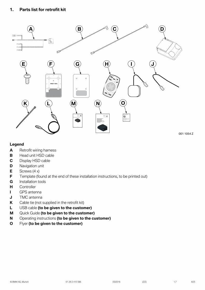
LegendA Retrofit wiring harnessB Head unit HSD cableC Display HSD cableD Navigation unitE Screws (4 x)F Template (found at the end of these installation instructions, to be printed out)G Installation toolsH ControllerI GPS antennaJ TMC antennaK Cable tie (not supplied in the retrofit kit)L USB cable (to be given to the customer)M Quick Guide (to be given to the customer)N Operating instructions (to be given to the customer)O Flyer (to be given to the customer)

2. Preparatory work
© BMW AG, Munich 01 29 2 410 586 03/2016 (Z/Z) 1.7 5/25
ISTA No.
Disconnect the negative battery cable 61 20 900
The following components must be removed first of allBottom right dashboard trim 51 45 195Glove box 64 11 380Head unit 65 12 320Central information display 65 50 057Controller (no longer required) 61 31 195
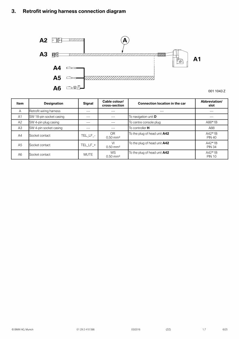
3. Retrofit wiring harness connection diagram
© BMW AG, Munich 01 29 2 410 586 03/2016 (Z/Z) 1.7 6/25
A1
A2
A3
A4A5A6
A
001 1043 Z
Item Designation Signal Cable colour/cross-section Connection location in the car Abbreviation/
slotA Retrofit wiring harness --- --- --- ---
A1 SW 18-pin socket casing --- --- To navigation unit D ---A2 SW 4-pin plug casing --- --- To centre console plug A88*1BA3 SW 4-pin socket casing --- --- To controller H A88
A4 Socket contact TEL_LF_- OR 0.50 mm²
To the plug of head unit A42 A42*1BPIN 40
A5 Socket contact TEL_LF_+ VI0.50 mm²
To the plug of head unit A42 A42*1BPIN 34
A6 Socket contact MUTE WS0.50 mm²
To the plug of head unit A42 A42*1BPIN 10
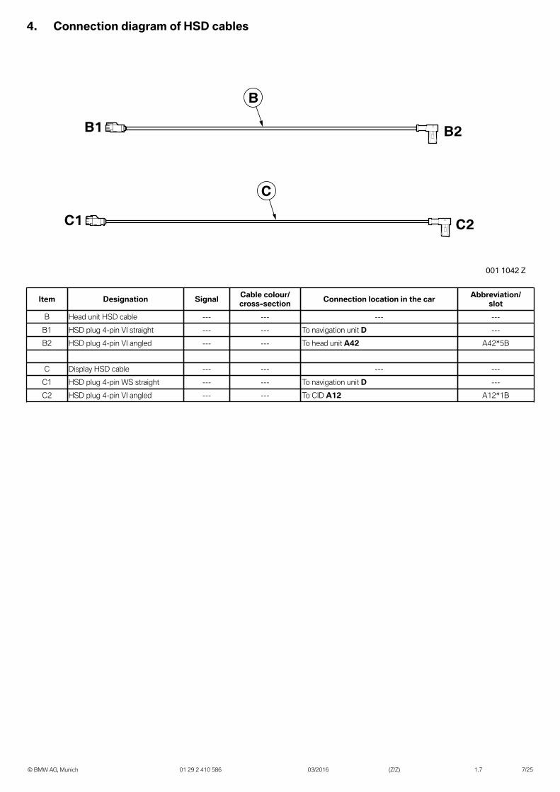
4. Connection diagram of HSD cables
© BMW AG, Munich 01 29 2 410 586 03/2016 (Z/Z) 1.7 7/25
B2B1
B
C2C1
C
001 1042 Z
Item Designation Signal Cable colour/cross-section Connection location in the car Abbreviation/
slotB Head unit HSD cable --- --- --- ---
B1 HSD plug 4-pin VI straight --- --- To navigation unit D ---B2 HSD plug 4-pin VI angled --- --- To head unit A42 A42*5B
C Display HSD cable --- --- --- ---C1 HSD plug 4-pin WS straight --- --- To navigation unit D ---C2 HSD plug 4-pin VI angled --- --- To CID A12 A12*1B
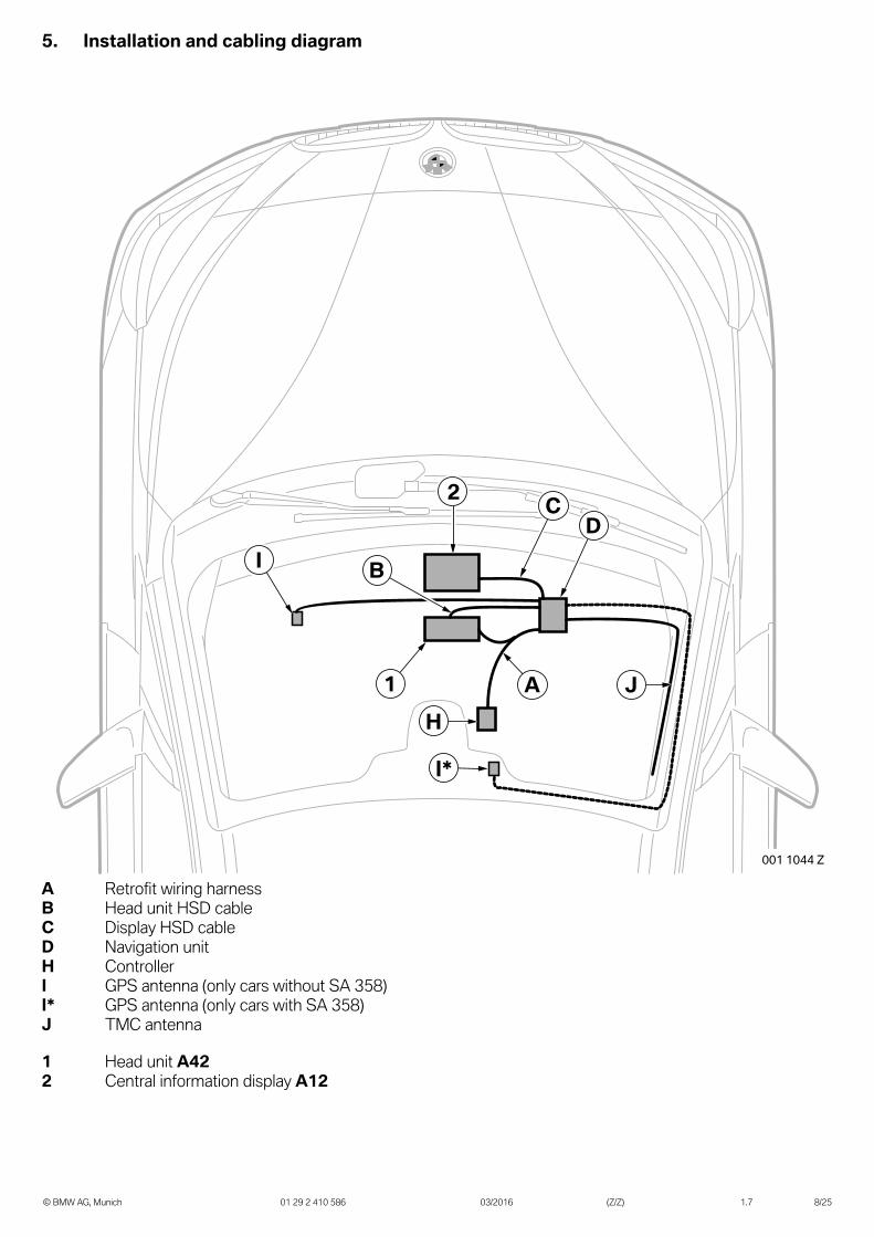
5. Installation and cabling diagram
© BMW AG, Munich 01 29 2 410 586 03/2016 (Z/Z) 1.7 8/25
001 1044 Z
2
A
B
J1
I*
H
CD
I
A Retrofit wiring harnessB Head unit HSD cableC Display HSD cableD Navigation unitH ControllerI GPS antenna (only cars without SA 358)I* GPS antenna (only cars with SA 358)J TMC antenna
1 Head unit A422 Central information display A12
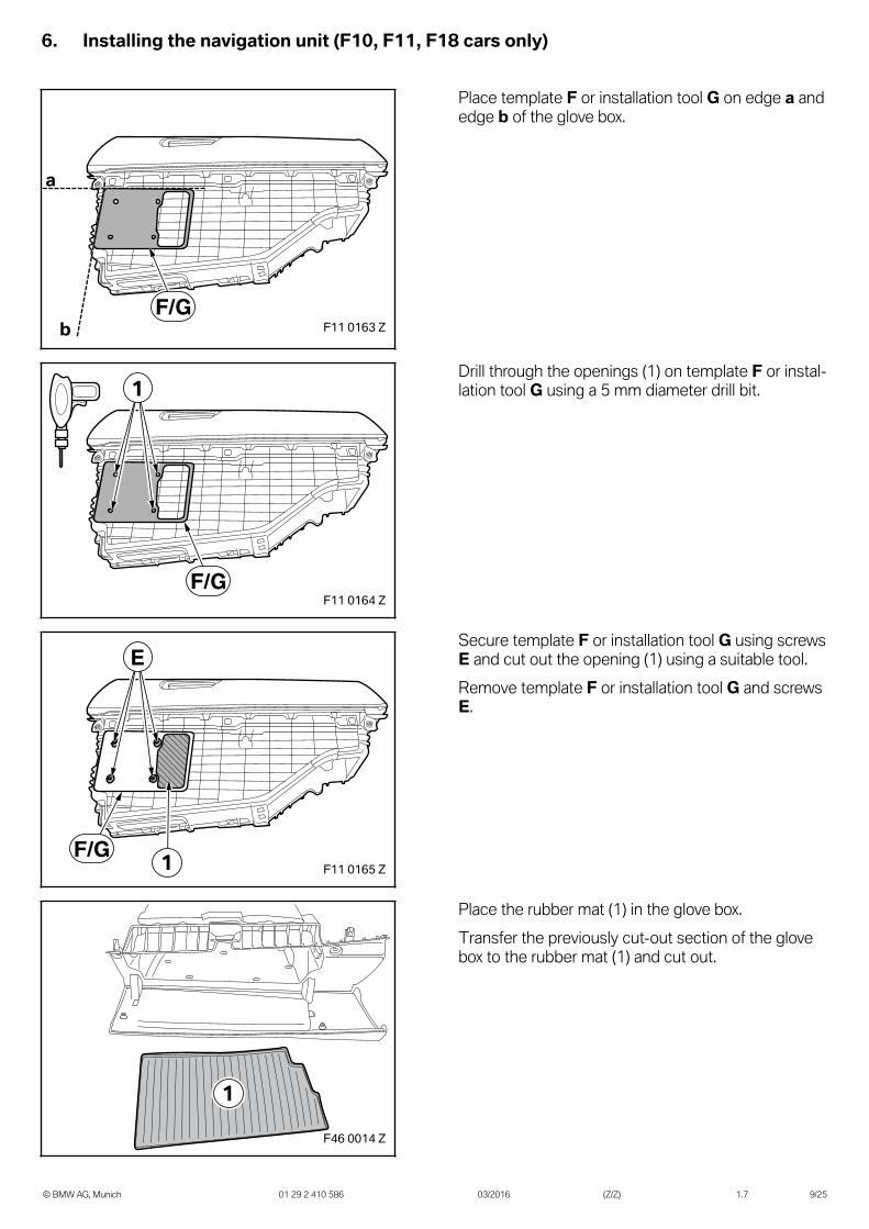
6. Installing the navigation unit (F10, F11, F18 cars only)
© BMW AG, Munich 01 29 2 410 586 03/2016 (Z/Z) 1.7 9/25
F11 0163 Z
a
bF/G
Place template F or installation tool G on edge a andedge b of the glove box.
F11 0164 Z
1
F/G
Drill through the openings (1) on template F or instal-lation tool G using a 5 mm diameter drill bit.
F11 0165 Z
E
1F/G
Secure template F or installation tool G using screwsE and cut out the opening (1) using a suitable tool.Remove template F or installation tool G and screwsE.
F46 0014 Z
1
Place the rubber mat (1) in the glove box.Transfer the previously cut-out section of the glovebox to the rubber mat (1) and cut out.
6. Installing the navigation unit (F10, F11, F18 cars only)
© BMW AG, Munich 01 29 2 410 586 03/2016 (Z/Z) 1.7 10/25
F11 0166 Z
E
D
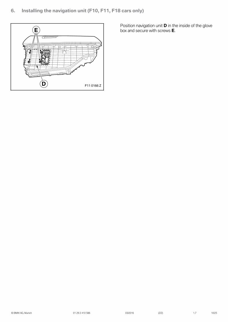
Position navigation unit D in the inside of the glovebox and secure with screws E.
7. Installing the navigation unit (F20, F21, F22, F23 cars only)
© BMW AG, Munich 01 29 2 410 586 03/2016 (Z/Z) 1.7 11/25
F23 0011 Z
6 m
m
27 mmF/G
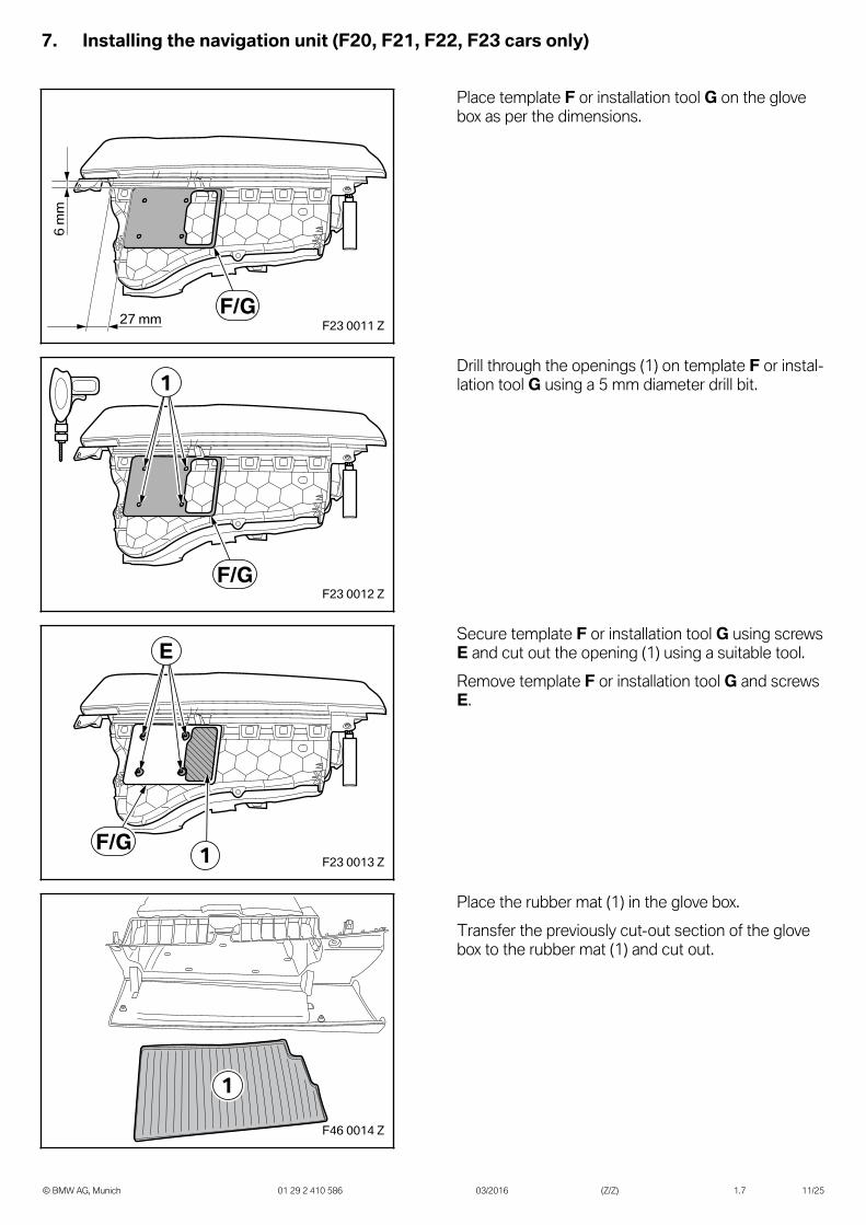
Place template F or installation tool G on the glovebox as per the dimensions.
F23 0012 Z
1
F/G
Drill through the openings (1) on template F or instal-lation tool G using a 5 mm diameter drill bit.
F23 0013 Z
E
1F/G
Secure template F or installation tool G using screwsE and cut out the opening (1) using a suitable tool.Remove template F or installation tool G and screwsE.
F46 0014 Z
1
Place the rubber mat (1) in the glove box.Transfer the previously cut-out section of the glovebox to the rubber mat (1) and cut out.
7. Installing the navigation unit (F20, F21, F22, F23 cars only)
© BMW AG, Munich 01 29 2 410 586 03/2016 (Z/Z) 1.7 12/25
F23 0014 Z
E
D
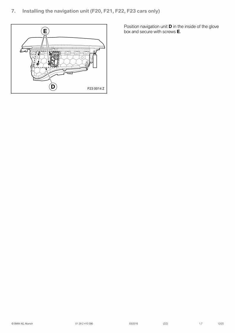
Position navigation unit D in the inside of the glovebox and secure with screws E.
8. Installing the navigation unit (F30, F31, F32, F33, F34, F35, F36 cars only)
© BMW AG, Munich 01 29 2 410 586 03/2016 (Z/Z) 1.7 13/25
F32 0010 Z
a
b
1
F/G
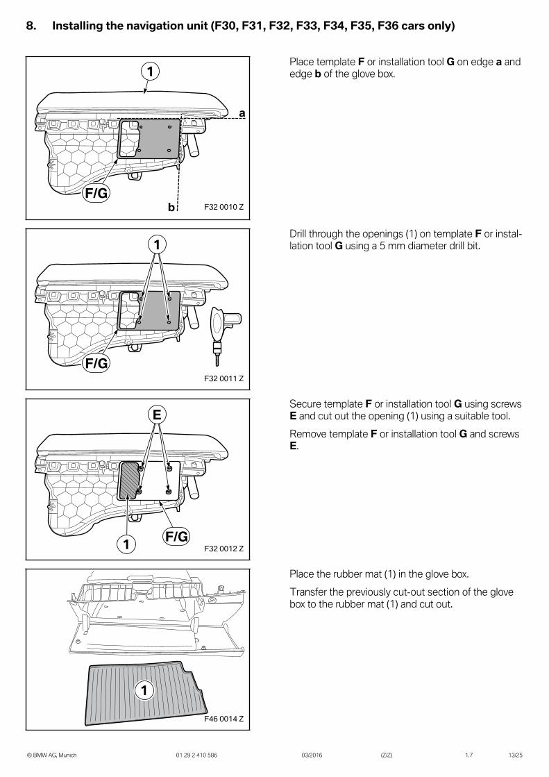
Place template F or installation tool G on edge a andedge b of the glove box.
F32 0011 Z
1
F/G
Drill through the openings (1) on template F or instal-lation tool G using a 5 mm diameter drill bit.
F32 0012 Z
E
1 F/G
Secure template F or installation tool G using screwsE and cut out the opening (1) using a suitable tool.Remove template F or installation tool G and screwsE.
F46 0014 Z
1
Place the rubber mat (1) in the glove box.Transfer the previously cut-out section of the glovebox to the rubber mat (1) and cut out.
8. Installing the navigation unit (F30, F31, F32, F33, F34, F35, F36 cars only)
© BMW AG, Munich 01 29 2 410 586 03/2016 (Z/Z) 1.7 14/25
F32 0013 ZD
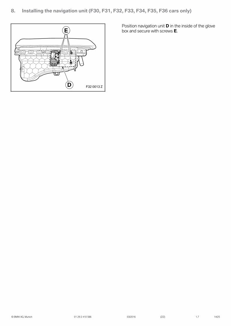
EPosition navigation unit D in the inside of the glovebox and secure with screws E.
9. Installing the navigation unit (F25, F26 cars only)
© BMW AG, Munich 01 29 2 410 586 03/2016 (Z/Z) 1.7 15/25
F26 0127 Z
34 mm
27 mm
F/G
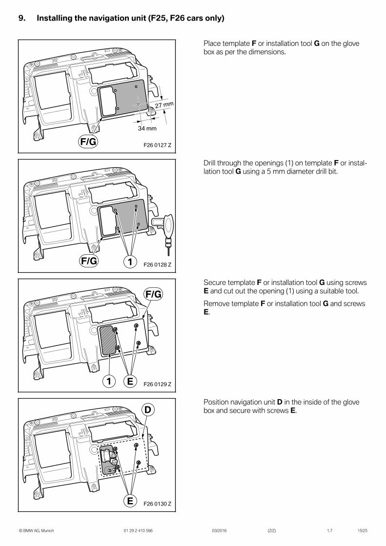
Place template F or installation tool G on the glovebox as per the dimensions.
F26 0128 Z1F/G
Drill through the openings (1) on template F or instal-lation tool G using a 5 mm diameter drill bit.
F26 0129 ZE1
F/GSecure template F or installation tool G using screwsE and cut out the opening (1) using a suitable tool.Remove template F or installation tool G and screwsE.
F26 0130 ZE
DPosition navigation unit D in the inside of the glovebox and secure with screws E.
10. Installing the navigation unit (F45, F46 cars only)
© BMW AG, Munich 01 29 2 410 586 03/2016 (Z/Z) 1.7 16/25
F46 0015 Z1
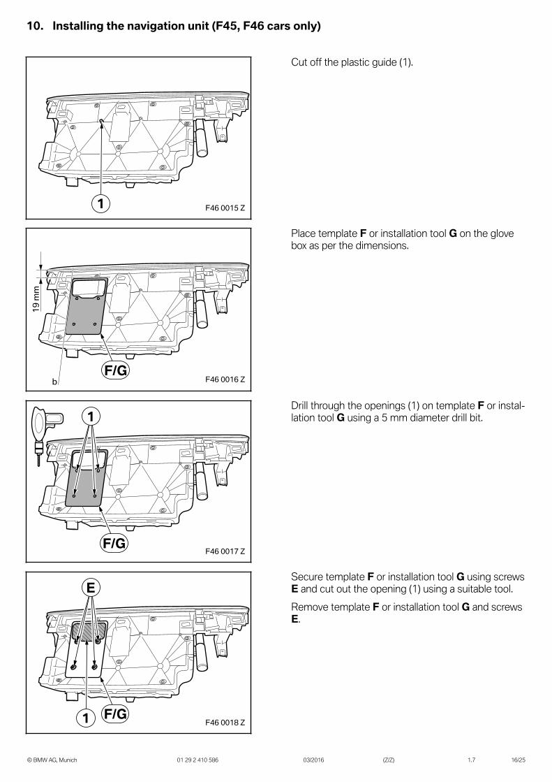
Cut off the plastic guide (1).
F46 0016 Z
19 m
m
bF/G
Place template F or installation tool G on the glovebox as per the dimensions.
F46 0017 Z
1
F/G
Drill through the openings (1) on template F or instal-lation tool G using a 5 mm diameter drill bit.
F46 0018 Z1
E
F/G
Secure template F or installation tool G using screwsE and cut out the opening (1) using a suitable tool.Remove template F or installation tool G and screwsE.
10. Installing the navigation unit (F45, F46 cars only)
© BMW AG, Munich 01 29 2 410 586 03/2016 (Z/Z) 1.7 17/25
F46 0014 Z
1
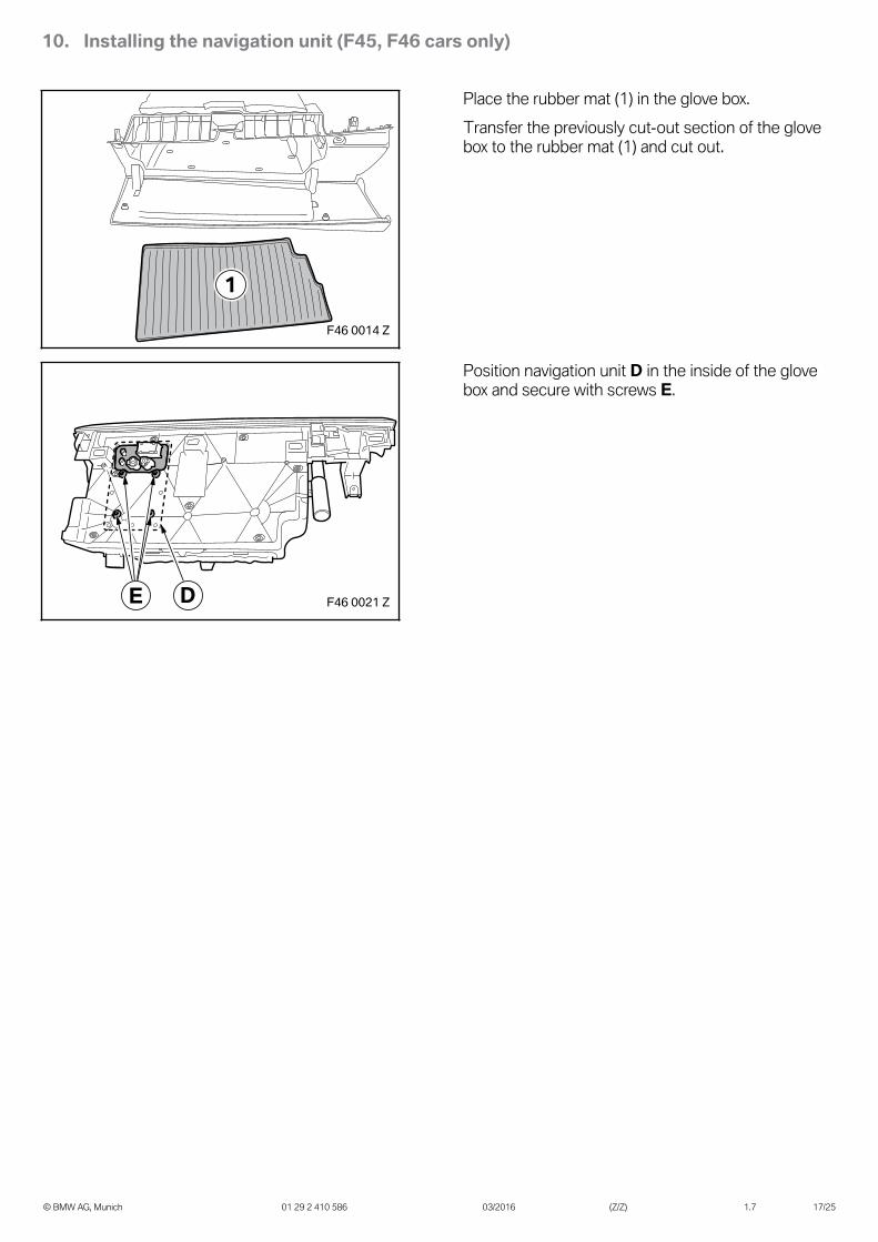
Place the rubber mat (1) in the glove box.Transfer the previously cut-out section of the glovebox to the rubber mat (1) and cut out.
F46 0021 ZDE
Position navigation unit D in the inside of the glovebox and secure with screws E.
11. Installing the navigation unit (F48, F49 cars only)
© BMW AG, Munich 01 29 2 410 586 03/2016 (Z/Z) 1.7 18/25
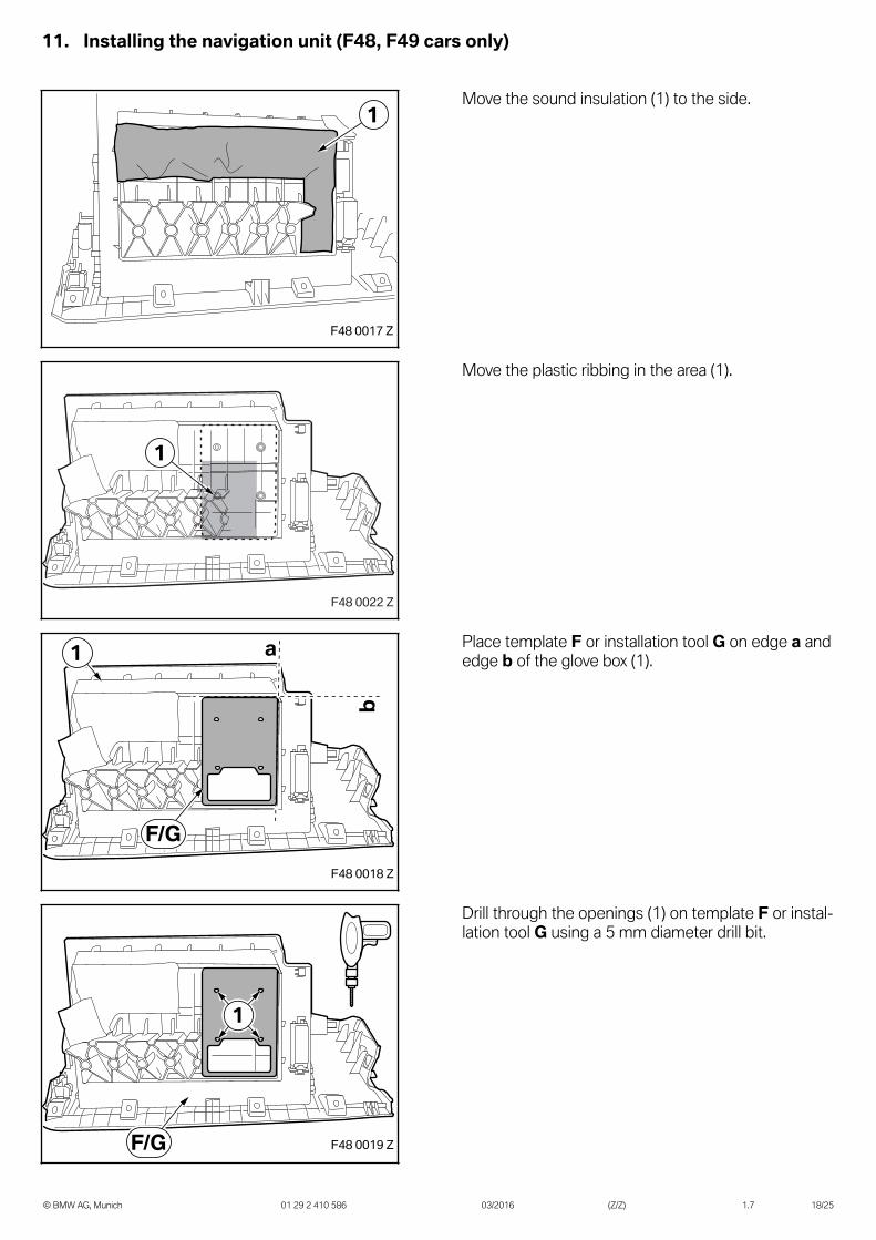
Move the sound insulation (1) to the side.
Move the plastic ribbing in the area (1).
Place template F or installation tool G on edge a andedge b of the glove box (1).
Drill through the openings (1) on template F or instal-lation tool G using a 5 mm diameter drill bit.
11. Installing the navigation unit (F48, F49 cars only)
© BMW AG, Munich 01 29 2 410 586 03/2016 (Z/Z) 1.7 19/25
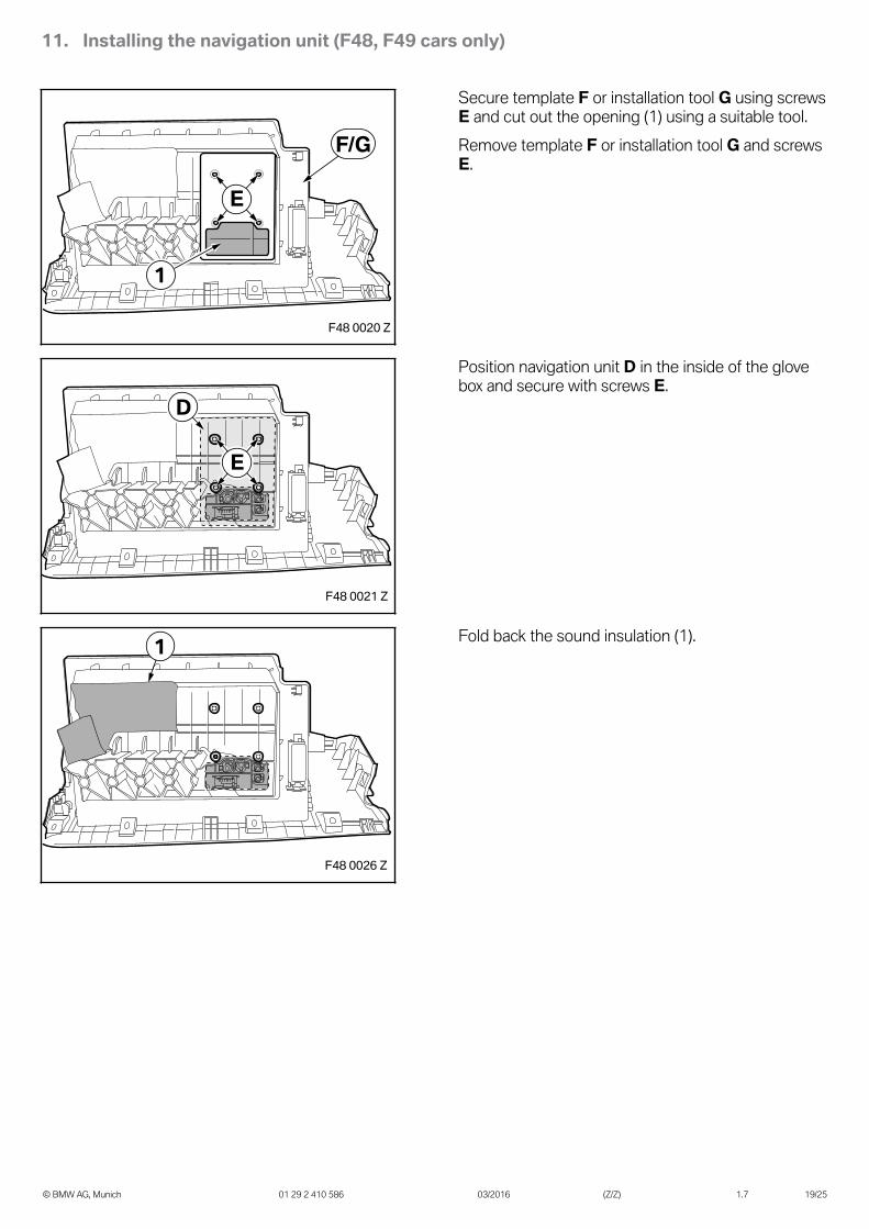
Secure template F or installation tool G using screwsE and cut out the opening (1) using a suitable tool.Remove template F or installation tool G and screwsE.
Position navigation unit D in the inside of the glovebox and secure with screws E.
Fold back the sound insulation (1).
12. Routing and connecting the retrofit wiring harness
© BMW AG, Munich 01 29 2 410 586 03/2016 (Z/Z) 1.7 20/25
I
001 1045 Z
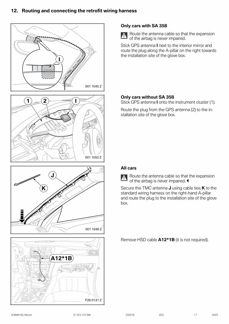
Only cars with SA 358
! Route the antenna cable so that the expansionof the airbag is never impaired.
Stick GPS antenna I next to the interior mirror androute the plug along the A-pillar on the right towardsthe installation site of the glove box.
I21
001 1052 Z
Only cars without SA 358Stick GPS antenna I onto the instrument cluster (1).Route the plug from the GPS antenna (2) to the in-stallation site of the glove box.
J
K
001 1046 Z
All cars
! Route the antenna cable so that the expansionof the airbag is never impaired.
Secure the TMC antenna J using cable ties K to thestandard wiring harness on the right-hand A-pillarand route the plug to the installation site of the glovebox.
A12*1B
F26 0131 Z
Remove HSD cable A12*1B (it is not required).
12. Routing and connecting the retrofit wiring harness
© BMW AG, Munich 01 29 2 410 586 03/2016 (Z/Z) 1.7 21/25
A4-A6A1 B1 C1
C2
A3A2
B2
C
B
A
F26 0132 Z
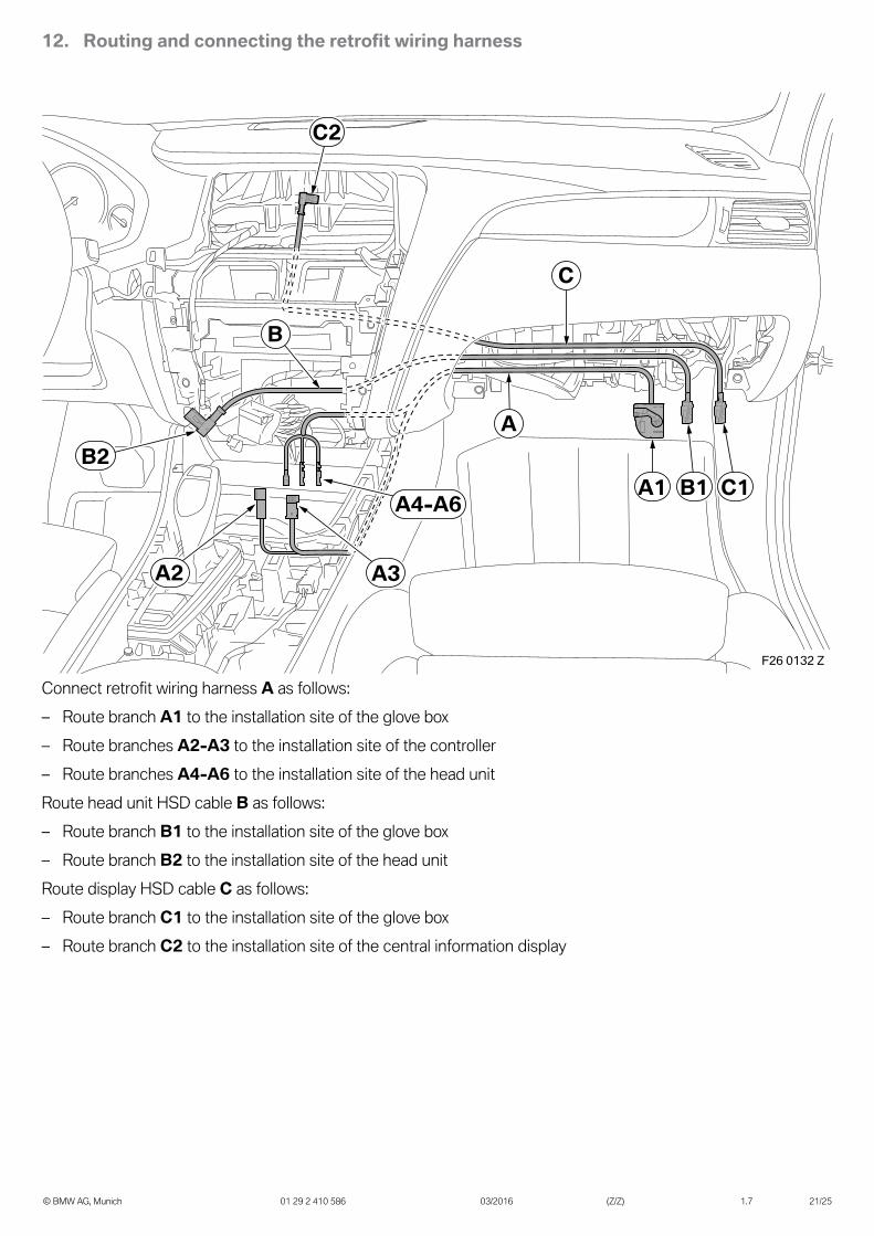
Connect retrofit wiring harness A as follows:– Route branch A1 to the installation site of the glove box– Route branches A2-A3 to the installation site of the controller– Route branches A4-A6 to the installation site of the head unitRoute head unit HSD cable B as follows:– Route branch B1 to the installation site of the glove box– Route branch B2 to the installation site of the head unitRoute display HSD cable C as follows:– Route branch C1 to the installation site of the glove box– Route branch C2 to the installation site of the central information display
12. Routing and connecting the retrofit wiring harness
© BMW AG, Munich 01 29 2 410 586 03/2016 (Z/Z) 1.7 22/25
A42*1B A4-A6
A88*1B
A1 B1 C1
C2
A2 A3
B2
A42*5B
A42
J
I
H
A12
F26 0133 Z
D
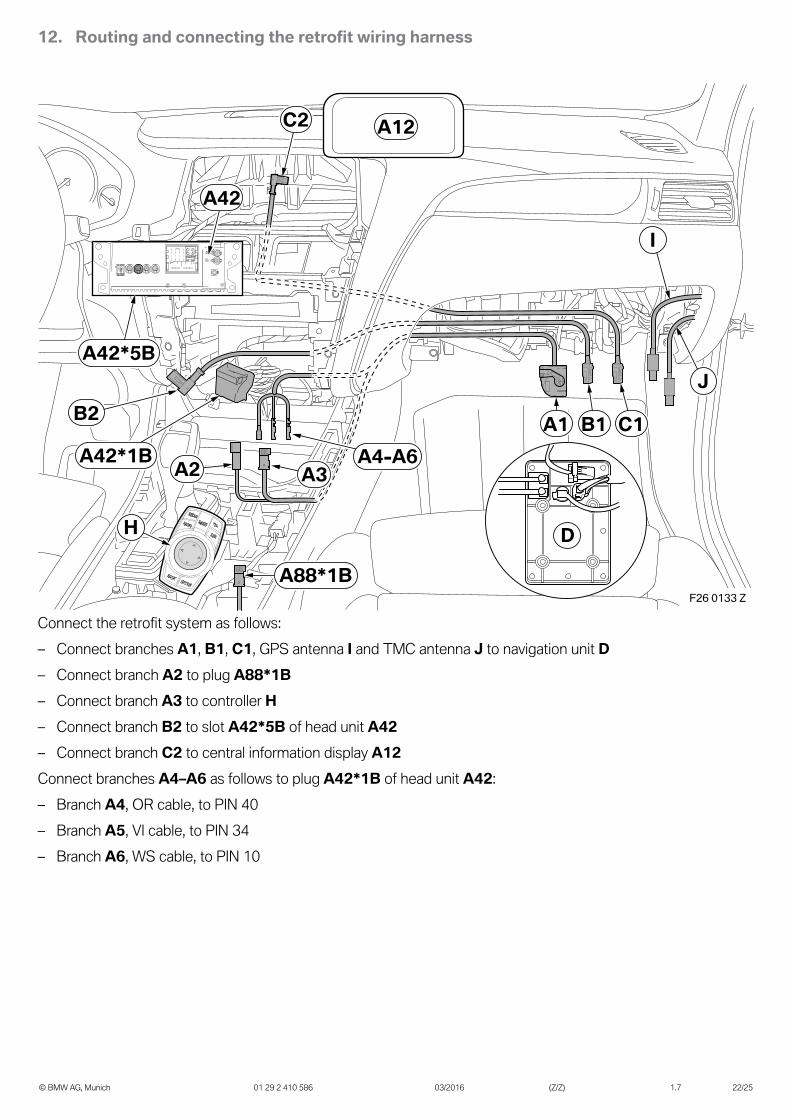
Connect the retrofit system as follows:– Connect branches A1, B1, C1, GPS antenna I and TMC antenna J to navigation unit D– Connect branch A2 to plug A88*1B– Connect branch A3 to controller H– Connect branch B2 to slot A42*5B of head unit A42– Connect branch C2 to central information display A12Connect branches A4–A6 as follows to plug A42*1B of head unit A42:– Branch A4, OR cable, to PIN 40– Branch A5, VI cable, to PIN 34– Branch A6, WS cable, to PIN 10

13. Concluding work and coding
© BMW AG, Munich 01 29 2 410 586 03/2016 (Z/Z) 1.7 23/25
The retrofit system requires programming/coding.– Connect the battery– Connect the battery charger to the car– Connect the car to the ISTA workshop system– Call up the ISTA/P car programming facility– If using ISTA/P, please follow the instructions in the ISTA/P application documentation– Select the "Integrated Navigation" retrofit via the – Conversions – path and work through the created action
plan– If necessary, carry out a car test using the ISTA system and note or work through any entered error memory– Carry out a function test and await a GPS fix, if necessary driving the vehicle outside the building– Re-assemble the car appropriately
The following parts must be given to the customer:– Decorative packaging– USB cable– Quick Guide– Instructions for use– Flyer
14. Wiring diagram
© BMW AG, Munich 01 29 2 410 586 03/2016 (Z/Z) 1.7 24/25
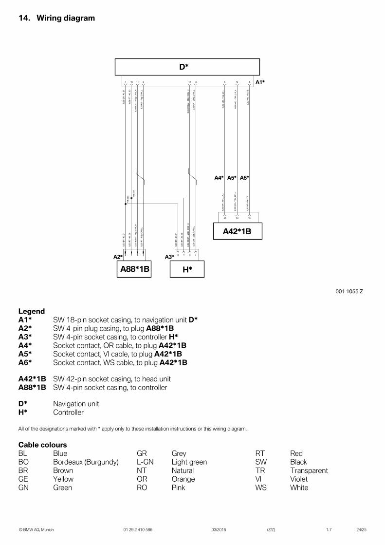
LegendA1* SW 18-pin socket casing, to navigation unit D*A2* SW 4-pin plug casing, to plug A88*1BA3* SW 4-pin socket casing, to controller H*A4* Socket contact, OR cable, to plug A42*1BA5* Socket contact, VI cable, to plug A42*1BA6* Socket contact, WS cable, to plug A42*1B
A42*1B SW 42-pin socket casing, to head unitA88*1B SW 4-pin socket casing, to controller
D* Navigation unitH* Controller
All of the designations marked with * apply only to these installation instructions or this wiring diagram.
Cable coloursBL Blue GR Grey RT RedBO Bordeaux (Burgundy) L-GN Light green SW BlackBR Brown NT Natural TR TransparentGE Yellow OR Orange VI VioletGN Green RO Pink WS White
15. Template
© BMW AG, Munich 01 29 2 410 586 03/2016 (Z/Z) 1.7 25/25
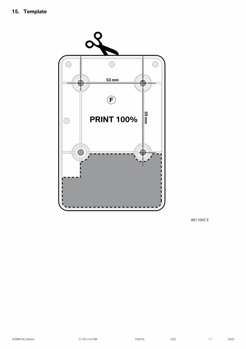
PRINT 100%
F
001 1047 Z
59 mm
53 mm