technical system catalogue climate control
TRANSCRIPT

Technical System Catalogue Climate Control
3 - 1 Technical System Catalogue/Climate control
Order information Catalogue 33, from page 393
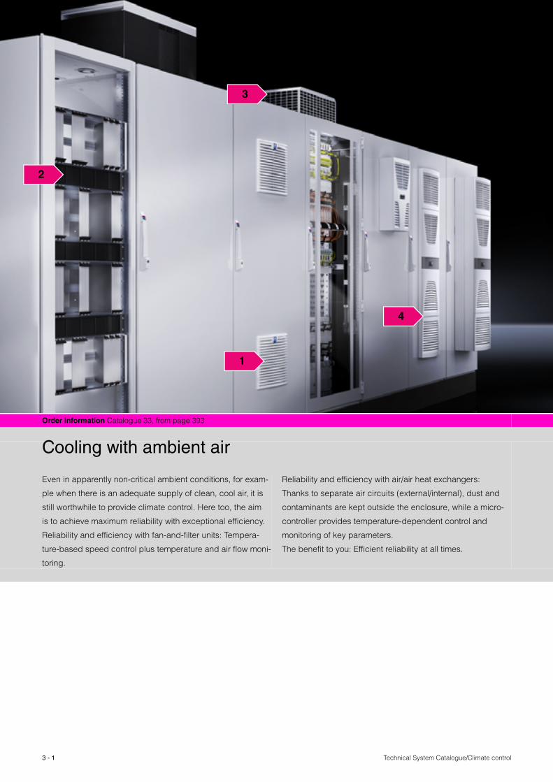
Cooling with ambient air
Even in apparently non-critical ambient conditions, for exam-
ple when there is an adequate supply of clean, cool air, it is
still worthwhile to provide climate control. Here too, the aim
is to achieve maximum reliability with exceptional efficiency.
Reliability and efficiency with fan-and-filter units: Tempera-
ture-based speed control plus temperature and air flow moni-
toring.
Reliability and efficiency with air/air heat exchangers:
Thanks to separate air circuits (external/internal), dust and
contaminants are kept outside the enclosure, while a micro-
controller provides temperature-dependent control and
monitoring of key parameters.
The benefit to you: Efficient reliability at all times.
1
4
3
2

3 - 2Technical System Catalogue/Climate control
1 TopTherm fan-and-filter units
Fan-and-filter units are ideal for dissipating heat loads cost-effectively.
The prerequisite is that the ambient air must be relatively clean with a temperature below the desired enclosure internal temperature.
EMC variants of the entire range of fan-and-filter units are also available.
2 Rack-mounted fans/tangential fans
Rack-mounted climate control components are fitted directly onto the 482.6 mm (19˝) mounting level. Positioning directly beneath the electronic components ensures effective cooling, and prevents the formation of hot-spots.
3 Fan systems
Ready-to-use modules, equipped with fans, for effective air throughput and minimal assembly work.
4 Air/air heat exchangers
The requirement for using air/air heat exchangers is that the ambient temperature must be below the required enclosure internal temperature.
Dust and contaminated ambient air are unable to ingress the enclosure, thanks to the two separate air circuits.
Cooling with ambient air

Technical System Catalogue/Climate control3 - 3
Project planning Page 6 Therm 6.1 software Page 3 Order information Catalogue 33, from page 394
Benefits at a glance:
� Innovative diagonal fan technology for higher,
more constant air throughput in the installed state
� Air throughput from 20 m3/h to 900 m3/h
� Fast, toolless assembly for output categories
20 m3/h to 900 m3/h
� IP 54 as standard (up to 700 m3/h)
� Air flow direction may be reversed from supply
(default setting) to exhaust
� All fans also available with EMC shielding
� Minimal installation depth
Fan-and-filter units are ideal for dissipating heat loads cost-
effectively. The prerequisite is that the ambient air must be
relatively clean with a temperature below the desired enclo-
sure internal temperature. The entire range of fan-and-filter
units is now also available with EMC shielding and a range
of rated operating voltages.
0
50
100
150
200
250
0 100 200 300 400 500 600
ΔPst
V.
V = Volumetric flow (m3/h)ΔPst = Stat. pressure difference (Pa)
= Resistance curve, outlet filter SK 3243.200= Old 50 Hz fan-and-filter unit SK 3326.XXX= New 50 Hz fan-and-filter unit SK 3243.XXX
.
Output comparison old/new
TopTherm fan-and-filter units
3 - 4Technical System Catalogue/Climate control
TopTherm fan-and-filter units
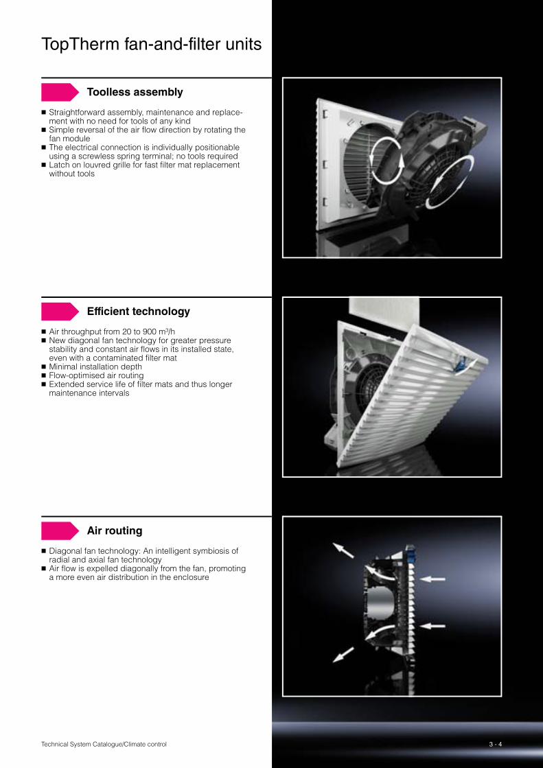
Toolless assembly
� Straightforward assembly, maintenance and replace-ment with no need for tools of any kind
� Simple reversal of the air flow direction by rotating the fan module
� The electrical connection is individually positionable using a screwless spring terminal; no tools required
� Latch on louvred grille for fast filter mat replacement without tools
Efficient technology
� Air throughput from 20 to 900 m³/h� New diagonal fan technology for greater pressure
stability and constant air flows in its installed state, even with a contaminated filter mat
� Minimal installation depth� Flow-optimised air routing� Extended service life of filter mats and thus longer
maintenance intervals
Air routing
� Diagonal fan technology: An intelligent symbiosis of radial and axial fan technology
� Air flow is expelled diagonally from the fan, promoting a more even air distribution in the enclosure
3 - 5 Technical System Catalogue/Climate control
TopTherm fan-and-filter units
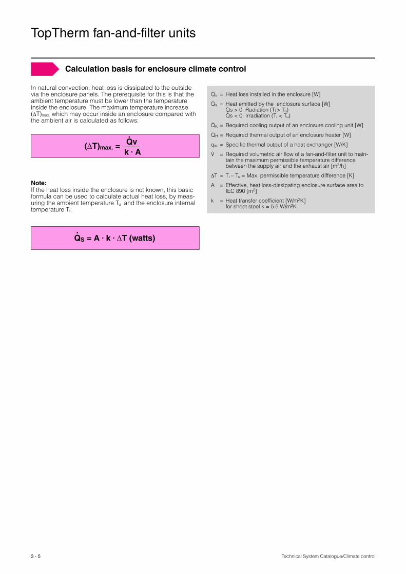
Calculation basis for enclosure climate control
In natural convection, heat loss is dissipated to the outside via the enclosure panels. The prerequisite for this is that the ambient temperature must be lower than the temperature inside the enclosure. The maximum temperature increase (ΔT)max. which may occur inside an enclosure compared with the ambient air is calculated as follows:
Note:If the heat loss inside the enclosure is not known, this basic formula can be used to calculate actual heat loss, by meas-uring the ambient temperature Tu and the enclosure internal temperature Ti:
(ΔT)max. =Qv k � A
.
QS = A � k � ΔT (watts).
Qv = Heat loss installed in the enclosure [W]
Qs = Heat emitted by the enclosure surface [W]Qs > 0: Radiation (Ti > Tu)Qs < 0: Irradiation (Ti < Tu)
QK = Required cooling output of an enclosure cooling unit [W]
QH = Required thermal output of an enclosure heater [W]
qw = Specific thermal output of a heat exchanger [W/K]
V = Required volumetric air flow of a fan-and-filter unit to main-tain the maximum permissible temperature difference between the supply air and the exhaust air [m3/h]
ΔT = Ti – Tu = Max. permissible temperature difference [K]
A = Effective, heat loss-dissipating enclosure surface area to IEC 890 [m2]
k = Heat transfer coefficient [W/m2K] for sheet steel k = 5.5 W/m2K
.
...
.
.
.
Technical System Catalogue/Climate control
TopTherm fan-and-filter units
3 - 6
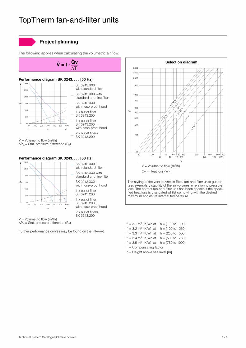
Project planning
The following applies when calculating the volumetric air flow:
Performance diagram SK 3243. . . . [50 Hz]
Performance diagram SK 3243. . . . [60 Hz]
Further performance curves may be found on the Internet.
V = f � Qv ΔT
. .
0
50
100
150
200
250
300
0 100 200 300 400 500 600
ΔPst
V.
V = Volumetric flow (m3/h)ΔPst = Stat. pressure difference (Pa)
.
SK 3243.XXX with standard filter
SK 3243.XXX with standard and fine filter
SK 3243.XXX with hose-proof hood
1 x outlet filter SK 3243.200
1 x outlet filter SK 3243.200 with hose-proof hood
2 x outlet filters SK 3243.200
0
50
100
150
200
250
300
0 100 200 300 400 500 600
ΔPst
V.
V = Volumetric flow (m3/h)ΔPst = Stat. pressure difference (Pa)
.
SK 3243.XXX with standard filter
SK 3243.XXX with standard and fine filter
SK 3243.XXX with hose-proof hood
1 x outlet filter SK 3243.200
1 x outlet filter SK 3243.200 with hose-proof hood
2 x outlet filtersSK 3243.200
Selection diagram
The styling of the vent louvres in Rittal fan-and-filter units guaran-tees exemplary stability of the air volumes in relation to pressure loss. The correct fan-and-filter unit has been chosen if the speci-fied heat loss is dissipated whilst complying with the desired maximum enclosure internal temperature.
V.
QV.
100
200
300
400
500
600
800
1000
1500
2000
3000
2500
Δ T
35 K
Δ T
40 K
Δ T
30 K
Δ T
20 K
Δ T
15 K
Δ T
10 K
Δ T
5 K
Δ T
25 K
30 50 70 90 300 500 70010 20 40 60 80 100 200 400 600 800
V = Volumetric flow (m3/h)
QV = Heat loss (W)
.
.
f = 3.1 m3 � K/Wh at h = ( 0 to 100)f = 3.2 m3 � K/Wh at h = (100 to 250)f = 3.3 m3 � K/Wh at h = (250 to 500)f = 3.4 m3 � K/Wh at h = (500 to 750)f = 3.5 m3 � K/Wh at h = (750 to 1000)f = Compensating factorh = Height above sea level [m]

Technical System Catalogue/Climate control
Rack-mounted fans/tangential fans
3 - 7
Therm 6.1 software Page 84 Order information Catalogue 33, from page 399
Benefits at a glance:
� Rapid installation on 482.6 mm (19˝) mounting levels.
� Direct, effective dissipation of heat loss, thanks to posi-
tioning beneath the assemblies.
� No externally mounted equipment to disrupt the aesthetic
appearance of the enclosure.
All rack-mounted climate control components are fitted
directly onto the 482.6 mm (19˝) mounting level for subracks.
Positioning directly beneath the electronic components
ensures effective cooling, and prevents the formation of
hot-spots.

3 - 8Technical System Catalogue/Climate control
Rack-mounted fans/tangential fans
Rack-mounted fans
� The rack-mounted fan slides into the guide frame like a drawer. Connectors on the rear ensure immediate contact.
� Installation options for the guide frame: Directly in the subrack, via two mounting brackets on the 482.6 mm (19˝) mounting angles.
� Ideal for avoiding hot-spots in fully populated enclo-sures.
� Also available with speed monitoring of the fans. A reduction in air flow or fan failure being signalled via two floating contacts.
Tangential fans
� 320 m3/h air throughput, 2 U: The high air throughput means that Rittal tangential fans are capable of dissi-pating large heat losses from the enclosure. The minimal noise generation of 52 dB creates a pleasant working environment.

Technical System Catalogue/Climate control
Fan systems
3 - 9
Project planning Page 13 Order information Catalogue 33, from page 401
Benefits at a glance:
� Fast assembly
� Targeted air routing to avoid hot-spots
� Perfect system integration
� Fully wired modules, ready to install
Ready-to-use, wired modules equipped with fans for numer-
ous Rittal enclosure system platforms offer effective air
throughput and minimal assembly work.
Choose from:
� Fan roofs
� Fan cross members for server enclosures (door-mounted)
� Internal fan mounting panels, and
� Enclosure internal fans
3 - 10Technical System Catalogue/Climate control
Fan systems
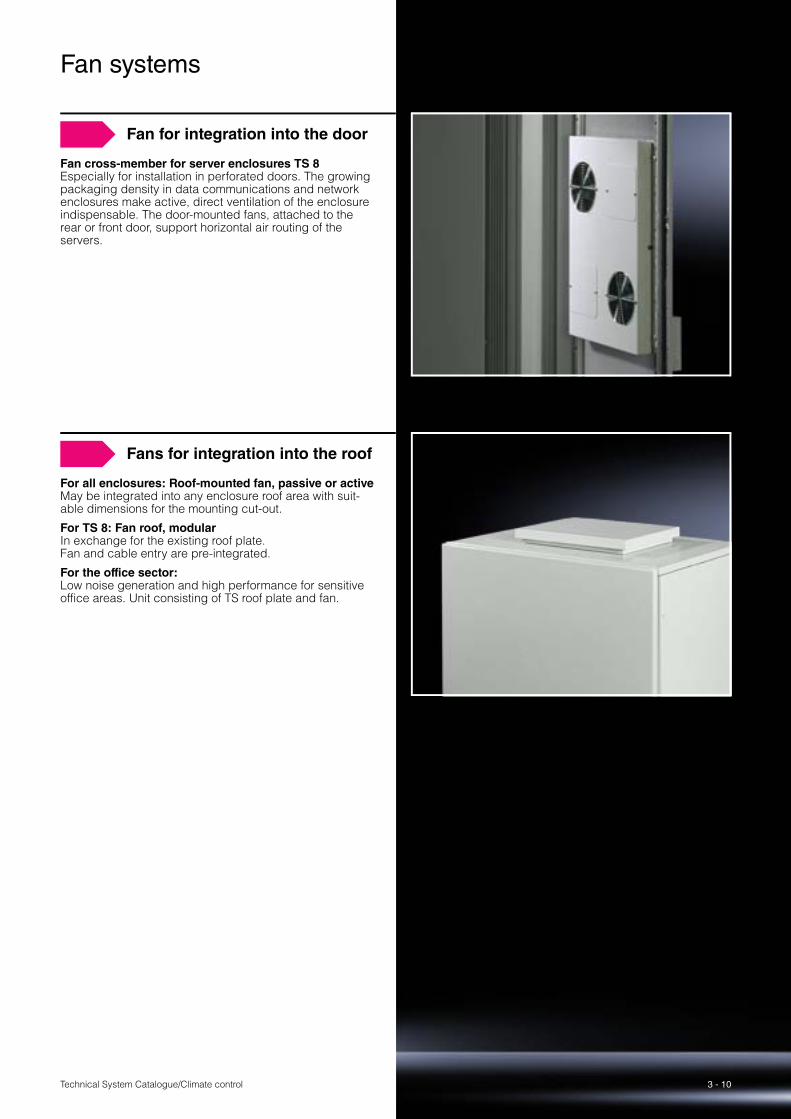
Fan for integration into the door
Fan cross-member for server enclosures TS 8Especially for installation in perforated doors. The growing packaging density in data communications and network enclosures make active, direct ventilation of the enclosure indispensable. The door-mounted fans, attached to the rear or front door, support horizontal air routing of the servers.
Fans for integration into the roof
For all enclosures: Roof-mounted fan, passive or activeMay be integrated into any enclosure roof area with suit-able dimensions for the mounting cut-out.
For TS 8: Fan roof, modularIn exchange for the existing roof plate. Fan and cable entry are pre-integrated.
For the office sector: Low noise generation and high performance for sensitive office areas. Unit consisting of TS roof plate and fan.

Technical System Catalogue/Climate control
Air/air heat exchangers
3 - 11
4 Project planning Page 13 Therm 6.1 software Page 85 Order information Catalogue 33, from page 408
Benefits at a glance:
� Specific thermal output from 17.5 W/K to 90 W/K
� External and internal circuit may be controlled separately
� Mounting cut-outs and enclosure dimensions identical
to TopTherm wall-mounted cooling units
� Suitable for external and internal mounting
� Top design identical to TopTherm wall-mounted cooling
units
Important
The temperature difference between the room temperature
and enclosure internal temperature will have a decisive effect
on the heat loss that may be dissipated.
The requirement for using air/air heat exchangers is that the
ambient temperature must be below the required enclosure
internal temperature. Dust and any aggressive ambient air is
unable to ingress the enclosure, thanks to the two separate
air circuits.

3 - 12Technical System Catalogue/Climate control
Air/air heat exchangers
Safety
� High protection categoryThanks to the seamlessly sealed heat exchanger module, a protection category of IP 54 to EN 60 529is achieved.
� High load capacityThe motors of the fans are equipped with thermal winding protection.
� Top quality: Guaranteed protection for your electronics.All devices in the Rittal TopTherm series are tested in accordance with the internationally recognised approvals (GS, UL).
Intelligent control
� Specific thermal output from 17.5 to 90 W/K.� With controller and digital temperature display.� Floating fault signal contact in case of overtemperature.� System analysis via display.
Platform strategy/installation
� Identical installation cut-outsfor various output categories.
� Easily retrofitted Thanks to the low weight, simple cut-outs and ease of installation of the heat exchangers, they may be easily retrofitted to an existing cabinet or enclosure.
� Simple maintenanceThe heat exchanger module is very easily removed, for effortless cleaning. The cleverly thought-out structure enables fast, economical maintenance.

3 - 13 Technical System Catalogue/Climate control
Air/air heat exchangers
Project planning
Calculate the specific thermal output of the heat exchanger:
Selection diagram
Note: For ambient temperatures that are lower than the desired enclosure internal temperature, the use of air/air heat exchangers may be appropriate, particularly in cases where there are dust, oil and aggressive substances in the ambi-ent air which must not be allowed to ingress the enclosure under any circumstances. A temperature difference of 10 K between the ambient temperature and the enclosure internal temperature is ideal.
ΔT = Temperature difference (K)Qv = Heat loss (W)qw = Specific thermal output (W/K)A = Enclosure surface area to IEC 890 (m2)k = Heat transfer coefficient (W/m2K)
for sheet steel k = 5.5 W/m2K
qw
ΔT
A
5 010152025
30
40
50
6070
10 30 50 70
024681012
3000 2000 1000 0 20 40 60 80
QV.
.
qw = QV – (A � ΔT � k)ΔT
.
Attention should be paid to installed equipment that is fitted with its own ventilation system, such as blowers and axial fans. If their air flow is directed against the chilled air flow of the heat exchanger, the air may short-circuit, bypassing the component and adequate climate control would no longer be guaranteed.
Note: Never direct the chilled air flow at active components.
Internal circuit – Wall-mounted units
Technical System Catalogue/Climate control
Air/air heat exchangers
3 - 14
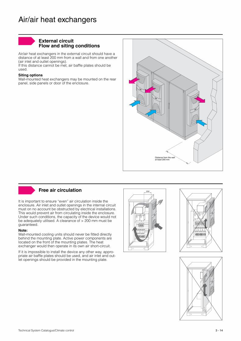
Air/air heat exchangers in the external circuit should have a distance of at least 200 mm from a wall and from one another (air inlet and outlet openings). If this distance cannot be met, air baffle plates should be used.
Siting optionsWall-mounted heat exchangers may be mounted on the rear panel, side panels or door of the enclosure.
Distance from the wallat least 200 mm
External circuit Flow and siting conditions
It is important to ensure “even” air circulation inside the enclosure. Air inlet and outlet openings in the internal circuit must on no account be obstructed by electrical installations. This would prevent air from circulating inside the enclosure. Under such conditions, the capacity of the device would not be adequately utilised. A clearance of > 200 mm must be guaranteed.
Note:Wall-mounted cooling units should never be fitted directly behind the mounting plate. Active power components are located on the front of the mounting plates. The heat exchanger would then operate in its own air short-circuit.
If it is impossible to install the device any other way, appro-priate air baffle plates should be used, and air inlet and out-let openings should be provided in the mounting plate.
200Free air circulation
Technical System Catalogue/Climate control3 - 15
3
1
4
2
Order information Catalogue 33, from page 413
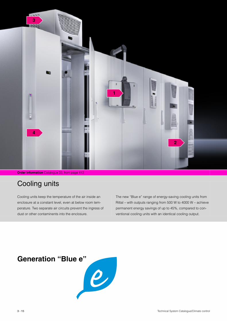
Cooling units
Cooling units keep the temperature of the air inside an
enclosure at a constant level, even at below room tem-
perature. Two separate air circuits prevent the ingress of
dust or other contaminents into the enclosure.
The new “Blue e” range of energy-saving cooling units from
Rittal – with outputs ranging from 500 W to 4000 W – achieve
permanent energy savings of up to 45%, compared to con-
ventional cooling units with an identical cooling output.
Generation “Blue e”

3 - 16Technical System Catalogue/Climate control
1 Thermoelectric coolers
The powerful, lightweight climate control units based on Peltier technology ensure efficient climate control of operating housings and small enclosures.
2 Wall-mounted cooling units
Standard features such as electric condensate evapora-tion and nano-coating of the condenser coil fins ensure a constant cooling output and easier maintenance. Depend-ing on the space and design requirements, internal mount-ing, partial internal mounting and external mounting are all possible.
3 Roof-mounted cooling units
Chilled air may be routed to satisfy specific cooling requirements using ducts in conjunction with up to four supply air spigots. In the external circuit, the heated air is expelled to the rear, left and right, and optionally upwards, allowing the enclosure to be sited in a bayed suite or close to the wall.
4 Modular climate control concept
With no mounting cut-outs whatsoever, 48 different combi-nation options with different dimensions, cooling outputs and voltages support a wide range of applications.
Technical System Catalogue/Climate control
Cooling units
3 - 17
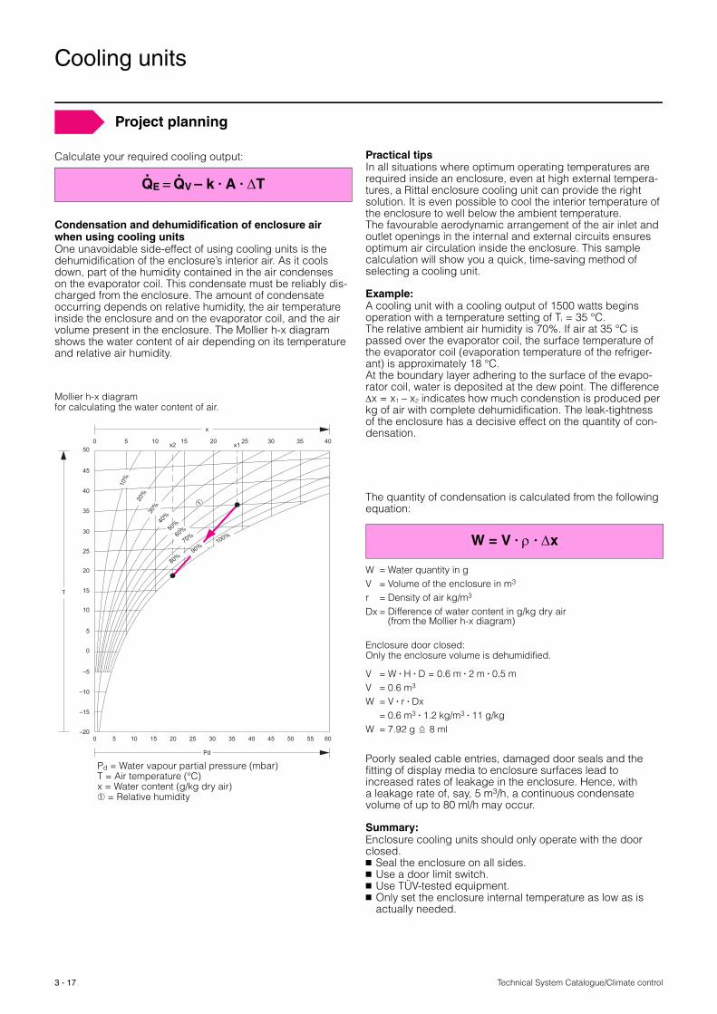
Condensation and dehumidification of enclosure air when using cooling unitsOne unavoidable side-effect of using cooling units is the dehumidification of the enclosure’s interior air. As it cools down, part of the humidity contained in the air condenses on the evaporator coil. This condensate must be reliably dis-charged from the enclosure. The amount of condensate occurring depends on relative humidity, the air temperature inside the enclosure and on the evaporator coil, and the air volume present in the enclosure. The Mollier h-x diagram shows the water content of air depending on its temperature and relative air humidity.
Mollier h-x diagram for calculating the water content of air.
Practical tipsIn all situations where optimum operating temperatures are required inside an enclosure, even at high external tempera-tures, a Rittal enclosure cooling unit can provide the right solution. It is even possible to cool the interior temperature of the enclosure to well below the ambient temperature. The favourable aerodynamic arrangement of the air inlet and outlet openings in the internal and external circuits ensures optimum air circulation inside the enclosure. This sample calculation will show you a quick, time-saving method of selecting a cooling unit.
Example:A cooling unit with a cooling output of 1500 watts begins operation with a temperature setting of Ti = 35 °C. The relative ambient air humidity is 70%. If air at 35 °C is passed over the evaporator coil, the surface temperature of the evaporator coil (evaporation temperature of the refriger-ant) is approximately 18 °C. At the boundary layer adhering to the surface of the evapo-rator coil, water is deposited at the dew point. The difference Δx = x1 – x2 indicates how much condenstion is produced per kg of air with complete dehumidification. The leak-tightness of the enclosure has a decisive effect on the quantity of con-densation.
The quantity of condensation is calculated from the following equation:
Enclosure door closed:Only the enclosure volume is dehumidified.
Poorly sealed cable entries, damaged door seals and the fitting of display media to enclosure surfaces lead to increased rates of leakage in the enclosure. Hence, with a leakage rate of, say, 5 m3/h, a continuous condensate volume of up to 80 ml/h may occur.
Summary:Enclosure cooling units should only operate with the door closed.� Seal the enclosure on all sides.� Use a door limit switch.� Use TÜV-tested equipment.� Only set the enclosure internal temperature as low as is
actually needed.
Pd
T
x
50
45
40
35
30
25
20
15
10
5
0
–5
–10
–15
–200
50 10 15 20 25x2 x1 30 35 40
6030 45155 10 20 25 35 40 50 55
10%
20%
30%
40%
50%
60%
70%
80%
100%
➀
90%
Pd = Water vapour partial pressure (mbar)T = Air temperature (°C)x = Water content (g/kg dry air) ➀ = Relative humidity
W = Water quantity in g V = Volume of the enclosure in m3 r = Density of air kg/m3 Dx = Difference of water content in g/kg dry air
(from the Mollier h-x diagram)
V = W � H � D = 0.6 m � 2 m � 0.5 mV = 0.6 m3 W = V � r � Dx
= 0.6 m3 � 1.2 kg/m3 � 11 g/kgW = 7.92 g 8 ml
Project planning
Calculate your required cooling output:
QE = QV – k � A � ΔT . .
W = V � ρ � Δx

Technical System Catalogue/Climate control
Cooling units
3 - 18
Selection criteria
Enclosure climate control places ever greater demands on integration and adaptation to the local conditions and the existing process control and monitoring system. Rittal offers the right solution to suit every requirement.
When selecting the appropriate cooling unit for your enclo-sure, please observe the following points:
� What is the installation type to IEC 890?(see page 5, calculation bases)
� What ambient conditions are anticipated (max. ambient temperature and humidity)?
� What is the required maximum internal temperature of the enclosure Ti?
� What is the heat loss from electronic components inside the enclosure?
� Is there a requirement regarding the protection category to EN 60 529/IEC 529?
� What type of ambient pollution, such as dust, oil and chemicals, are the cooling units exposed to?
� For bayed enclosure suites, the output irradiated from neighbouring units may also need to be taken into account.
� Good ventilation should be ensured at the site of installa-tion (for example, the heat dissipated by the cooling unit may cause a significant rise in the temperature of small rooms).
� Particularly with poor ambient conditions, such as dirt or small, unvented rooms, air/water heat exchangers should be used.
In order to ensure the proper use of enclosure cooling units, the following points should be observed:
1. The unit must only be installed and opened by author-ised, expertly trained personnel.
2. Choose a location for the cooling unit which ensures excellent ventilation. The site must be free from exces-sive contamination and moisture. For example, the atmosphere must not contain any conductive dusts or corrosive media.
3. The mains connection data (connection voltage and fre-quency) specified on the rating plate must be observed. In the case of 400 V, 2~ cooling units, we recommend the use of transformer circuit-breakers, and for three-phase units, the use of motor circuit-breakers is advis-able.
4. The prescribed electrical protection devices must be connected upstream of the unit. No additional tempera-ture control may be connected upstream of the unit at the supply end. The pre-fuse specified on the rating plate should be provided as line protection. Observe the locally valid regulations when installing.
5. Where a door contact switch is used, a shielded cable should be used in environments with increased levels of electromagnetic interference.
6. The temperature range specified on the rating plate must be observed when operating the cooling unit, both indoors and outdoors.
7. The enclosure must be sealed on all sides (IP 54).
8. The air inlet and outlet openings in the internal circuit of the cooling unit must not be obstructed.
9. The cold air flow should not be pointed directly at elec-tronic components, to prevent the formation of conden-sation.
10. The unit must only be installed horizontally, in accord-ance with the prescribed installation position. The maxi-mum permissible deviation from the horizontal is 2°.
11. After disconnecting from the supply voltage, the cooling circuit of the cooling unit must not be switched back on for at least 5 minutes.
12. The customer must not make any modifications to the cooling unit.
13. The heat loss of the components installed in the enclo-sure must not exceed the specific useful cooling output of the cooling unit.
14. The installation instructions contained in the cooling unit manual must be observed in full.
Appropriate use of enclosure cooling units
Technical System Catalogue/Climate control
Cooling units
3 - 19
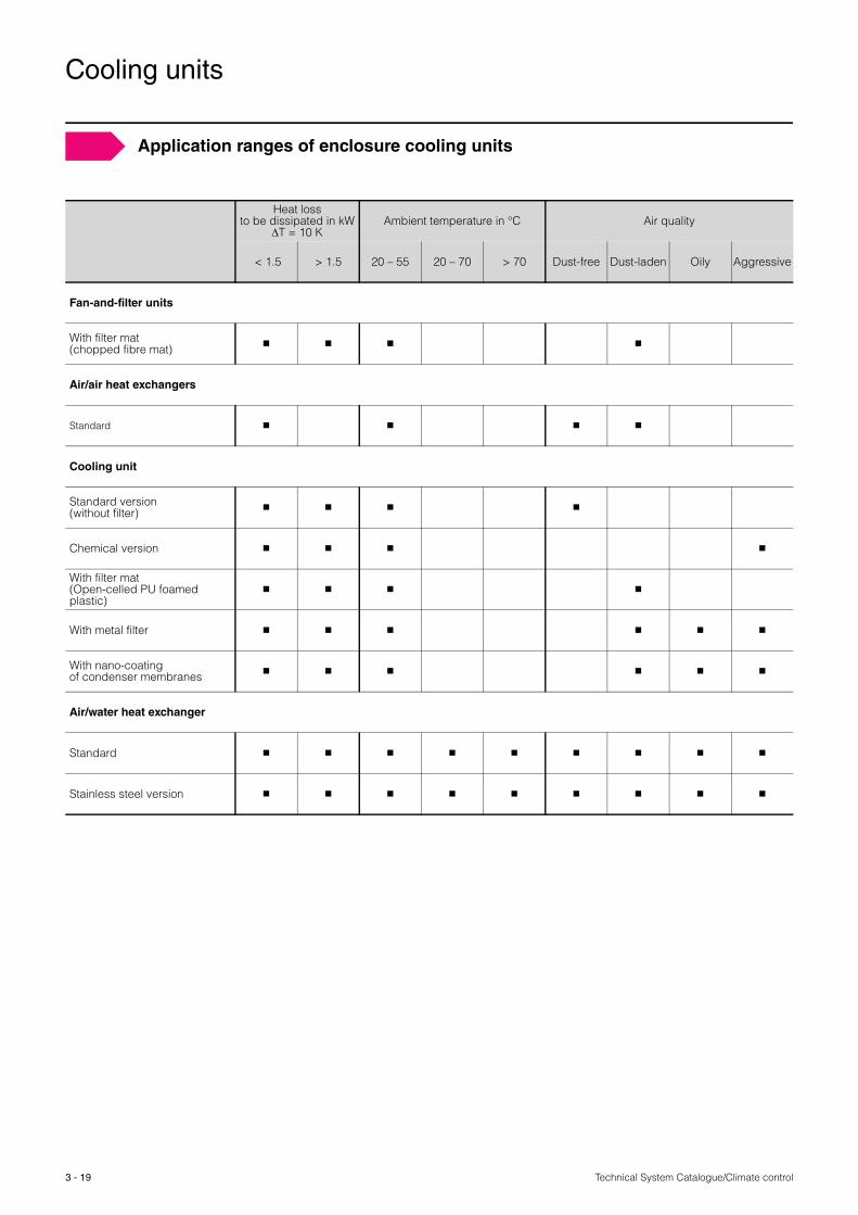
Heat loss to be dissipated in kW
ΔT = 10 KAmbient temperature in °C Air quality
< 1.5 > 1.5 20 – 55 20 – 70 > 70 Dust-free Dust-laden Oily Aggressive
Fan-and-filter units
With filter mat(chopped fibre mat) � � � �
Air/air heat exchangers
Standard � � � �
Cooling unit
Standard version(without filter) � � � �
Chemical version � � � �
With filter mat(Open-celled PU foamed plastic)
� � � �
With metal filter � � � � � �
With nano-coating of condenser membranes � � � � � �
Air/water heat exchanger
Standard � � � � � � � � �
Stainless steel version � � � � � � � � �
Application ranges of enclosure cooling units
Technical System Catalogue/Climate control
Cooling units
3 - 20
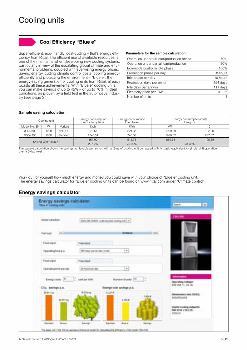
Cool Efficiency “Blue e”
Super-efficient, eco-friendly, cost-cutting – that’s energy effi-ciency from Rittal. The efficient use of available resources is one of the main aims when developing new cooling systems, particularly in view of the escalating global climate and envi-ronmental problems, coupled with ever-rising energy prices. Saving energy, cutting climate control costs, cooling energy-efficiently and protecting the environment – “Blue e”, the energy-saving generation of cooling units from Rittal, already boasts all these achievements. With “Blue e” cooling units, you can make savings of up to 45% – or up to 70% in ideal conditions, as proven by a field test in the automotive indus-try (see page 27).
Parameters for the sample calculation:
Operation under full load/production phase 70%Operation under partial load/production 30%Eco-mode control in idle phase 100%Production phase per day 8 hoursIdle phase per day 16 hoursProduction days per annum 254 daysIdle days per annum 111 daysElectricity price per kWh 0.12 €Number of units 1
Sample saving calculation
Cooling unit Energy consumption Production phase
Energy consumption Idle phase
Energy consumption/costs total/p. a.
Model No. SK W Variant kWh kWh kWh €3304.500 1000 “Blue e” 878.64 221.35 1099.99 132.003304.100 1000 Standard 1240.54 740.08 1980.62 237.67
Saving with “Blue e”361.90 518.73 880.63 105.6829.17% 70.09% 44.46%
The sample calculation shows the savings achievable per annum with a “Blue e” cooling unit compared with its basic equivalent for single-shift operation over a 5-day week.
Work out for yourself how much energy and money you could save with your choice of “Blue e” cooling unit: The energy savings calculator for “Blue e” cooling units can be found on www.rittal.com under “Climate control”.
Energy savings calculator

Technical System Catalogue/Climate control
Cooling units
3 - 21
In the outer circuit, enclosure cooling units should be spaced > 200 mm from the wall and/or from each other (air inlet and outlet openings). In order to ensure adequate air circulation, at least one air outlet opening must be kept free. If this clearance cannot be maintained, air baffle plates will need to be used.
Roof-mounted cooling unitsA range of installation positions may be considered for roof-mounted cooling units, due, in part, to the routing in the external air circuit. Thanks to this, together with their com-pact dimensions, roof-mounted cooling units may even be installed in low-height rooms and with bayed enclosure suites. As supplied, the units draw air in at the front and exhaust it via the rear and sides. Exhaust via the top is also available as an option, however, regardless of the type of installation, the units must be free to exhaust air via at least one of these routes.
Wall-mounted cooling unitsThere are no restrictions to the installation position of wall-mounted cooling units provided that the air intake and exhaust areas at the front are not obscured. Wall-mounted cooling units may be mounted on the rear panel, side panels or door of the enclosure.
Distance from the wallat least 200 mm
External circuit –Flow and siting conditions
Attention should be paid to installed equipment that is fitted with its own ventilation system, such as blowers and axial fans. If their air flow is directed against the chilled air flow of the cooling unit, the air may short-circuit, bypassing the component. In the worst case, the internal safety systems of the cooling unit would discontinue cooling operation.
Note:Never direct the chilled air flow at active components.
Accessories:Air diverter, see Cat. 33, page 475.
651)
External air circuit
Internal air circuit
1) 115 mm for SK 3213.330
Air diverterInternal circuit – Wall-mounted unitsFlow conditions
Technical System Catalogue/Climate control
Cooling units
3 - 22
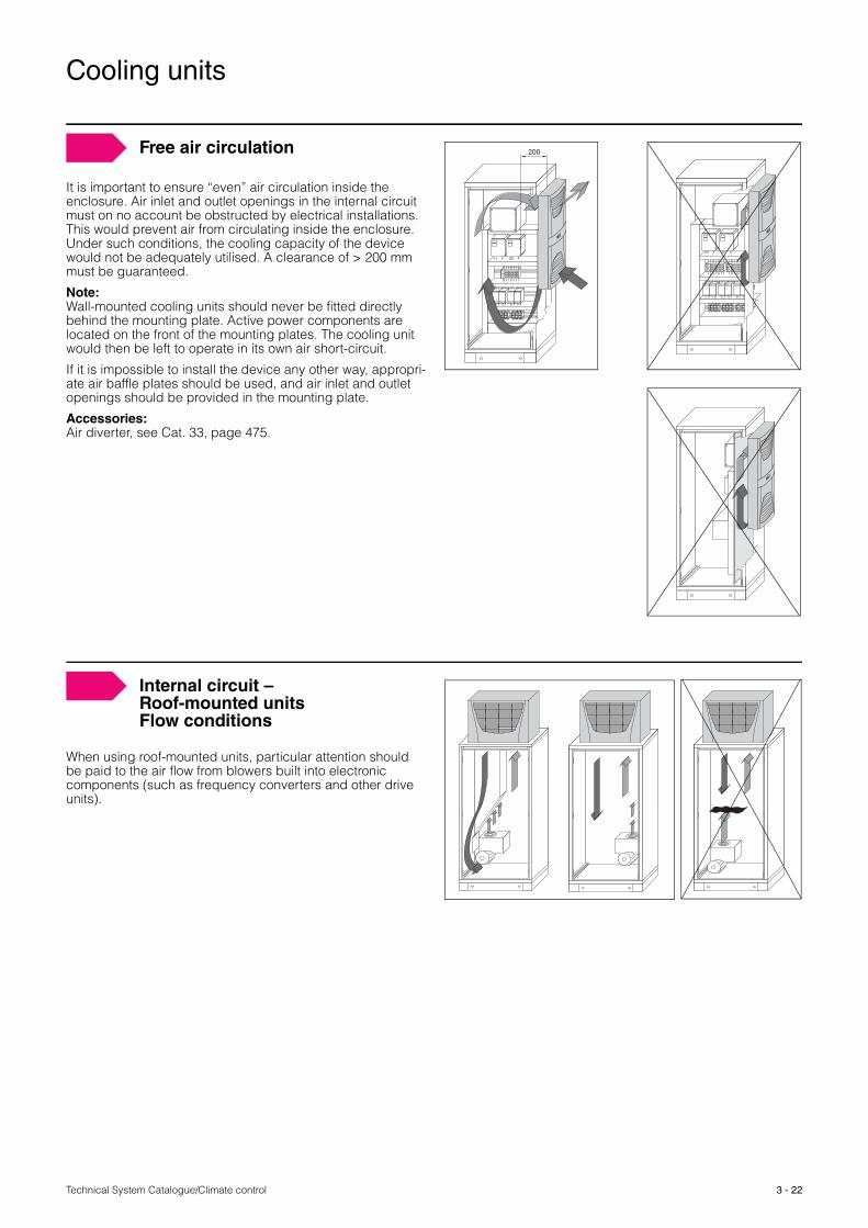
It is important to ensure “even” air circulation inside the enclosure. Air inlet and outlet openings in the internal circuit must on no account be obstructed by electrical installations. This would prevent air from circulating inside the enclosure. Under such conditions, the cooling capacity of the device would not be adequately utilised. A clearance of > 200 mm must be guaranteed.
Note:Wall-mounted cooling units should never be fitted directly behind the mounting plate. Active power components are located on the front of the mounting plates. The cooling unit would then be left to operate in its own air short-circuit.
If it is impossible to install the device any other way, appropri-ate air baffle plates should be used, and air inlet and outlet openings should be provided in the mounting plate.
Accessories:Air diverter, see Cat. 33, page 475.
200Free air circulation
When using roof-mounted units, particular attention should be paid to the air flow from blowers built into electronic components (such as frequency converters and other drive units).
Internal circuit – Roof-mounted unitsFlow conditions
Technical System Catalogue/Climate control
Cooling units
3 - 23
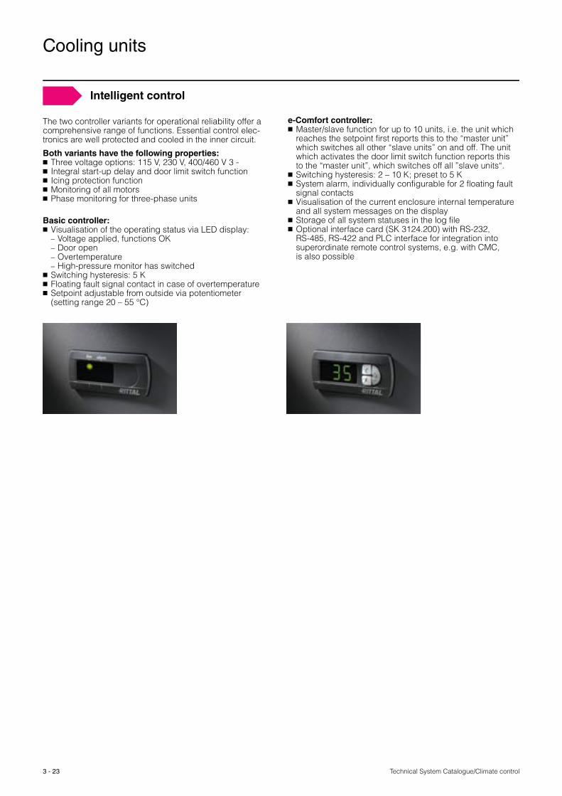
The two controller variants for operational reliability offer a comprehensive range of functions. Essential control elec-tronics are well protected and cooled in the inner circuit.
Both variants have the following properties: � Three voltage options: 115 V, 230 V, 400/460 V 3 ˜ � Integral start-up delay and door limit switch function � Icing protection function� Monitoring of all motors� Phase monitoring for three-phase units
Basic controller: � Visualisation of the operating status via LED display:− Voltage applied, functions OK− Door open− Overtemperature− High-pressure monitor has switched
� Switching hysteresis: 5 K� Floating fault signal contact in case of overtemperature� Setpoint adjustable from outside via potentiometer
(setting range 20 – 55 °C)
Intelligent control
e-Comfort controller: � Master/slave function for up to 10 units, i.e. the unit which
reaches the setpoint first reports this to the “master unit” which switches all other “slave units” on and off. The unit which activates the door limit switch function reports this to the “master unit”, which switches off all ”slave units“.
� Switching hysteresis: 2 – 10 K; preset to 5 K� System alarm, individually configurable for 2 floating fault
signal contacts� Visualisation of the current enclosure internal temperature
and all system messages on the display� Storage of all system statuses in the log file� Optional interface card (SK 3124.200) with RS-232,
RS-485, RS-422 and PLC interface for integration into superordinate remote control systems, e.g. with CMC, is also possible
Technical System Catalogue/Climate control
Thermoelectric coolers
3 - 24
Software & Service Page 26 Order information Catalogue 33, page 414
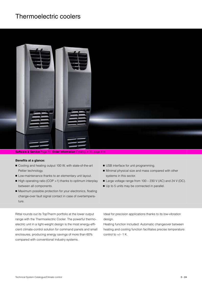
Benefits at a glance:
� Cooling and heating output 100 W, with state-of-the-art
Peltier technology.
� Low-maintenance thanks to an elementary unit layout.
� High operating ratio (COP >1) thanks to optimum interplay
between all components.
� Maximum possible protection for your electronics, floating
change-over fault signal contact in case of overtempera-
ture.
� USB interface for unit programming.
� Minimal physical size and mass compared with other
systems in this sector.
� Large voltage range from 100 – 230 V (AC) and 24 V (DC).
� Up to 5 units may be connected in parallel.
Rittal rounds out its TopTherm portfolio at the lower output
range with the Thermoelectric Cooler. The powerful thermo-
electric unit in a light-weight design is the most energy-effi-
cient climate-control solution for command panels and small
enclosures, producing energy savings of more than 60%
compared with conventional industry systems.
Ideal for precision applications thanks to its low-vibration
design.
Heating function included: Automatic changeover between
heating and cooling function facilitates precise temperature
control to +/– 1 K.
Thermoelectric coolers
3 - 25 Technical System Catalogue/Climate control
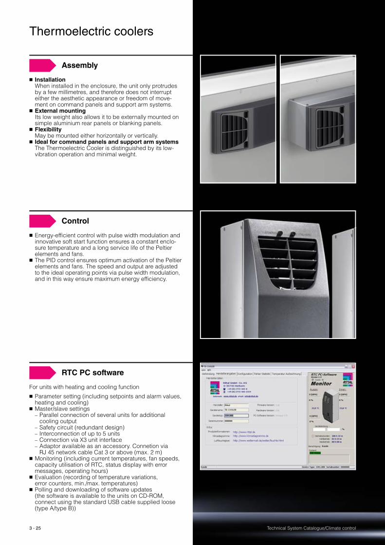
Assembly
� InstallationWhen installed in the enclosure, the unit only protrudes by a few millimetres, and therefore does not interrupt either the aesthetic appearance or freedom of move-ment on command panels and support arm systems.
� External mountingIts low weight also allows it to be externally mounted on simple aluminium rear panels or blanking panels.
� FlexibilityMay be mounted either horizontally or vertically.
� Ideal for command panels and support arm systems The Thermoelectric Cooler is distinguished by its low-vibration operation and minimal weight.
Control
� Energy-efficient control with pulse width modulation and innovative soft start function ensures a constant enclo-sure temperature and a long service life of the Peltier elements and fans.
� The PID control ensures optimum activation of the Peltier elements and fans. The speed and output are adjusted to the ideal operating points via pulse width modulation, and in this way ensure maximum energy efficiency.
RTC PC software
For units with heating and cooling function
� Parameter setting (including setpoints and alarm values, heating and cooling)
� Master/slave settings− Parallel connection of several units for additional
cooling output− Safety circuit (redundant design)− Interconnection of up to 5 units− Connection via X3 unit interface− Adaptor available as an accessory. Connetion via
RJ 45 network cable Cat 3 or above (max. 2 m)� Monitoring (including current temperatures, fan speeds,
capacity utilisation of RTC, status display with error messages, operating hours)
� Evaluation (recording of temperature variations, error counters, min./max. temperatures)
� Polling and downloading of software updates (the software is available to the units on CD-ROM, connect using the standard USB cable supplied loose (type A/type B))

Technical System Catalogue/Climate control
“Blue e” cooling units
3 - 26
Cooling units Page 15 Air/water heat exchangers Page 39
Generation “Blue e”Make permanent energy savings with Rittal cooling units
� Energy-saving cooling units in the output range from
500 W to 4000 W
� In addition to the new controller, the components used
(such as fan, compressor, evaporator coil and condenser)
have also been optimised in terms of their energy effi-
ciency.
� Savings of up to 45% energy consumption with the same
cooling output (ideally 70% compared with a conventional
Rittal TopTherm Plus cooling unit in field trials)
Eco-mode controlIntelligent, targeted use of energy thanks to the new eco-mode control from Rittal
Cooling switches off: The interior fan only runs to ensure air circulation inside the enclosureThe interior fan is switched off.The interior fan is switched on for 30 seconds every 10 minutes to briefly blend the air. The interior fan is switched back on.
1
2
3
4
Generation “Blue e”
35 °C
25 °C
Temperature
Energy input
1
2 3
4
10 min. 10 min.30 sec.
Technical System Catalogue/Climate control3 - 27
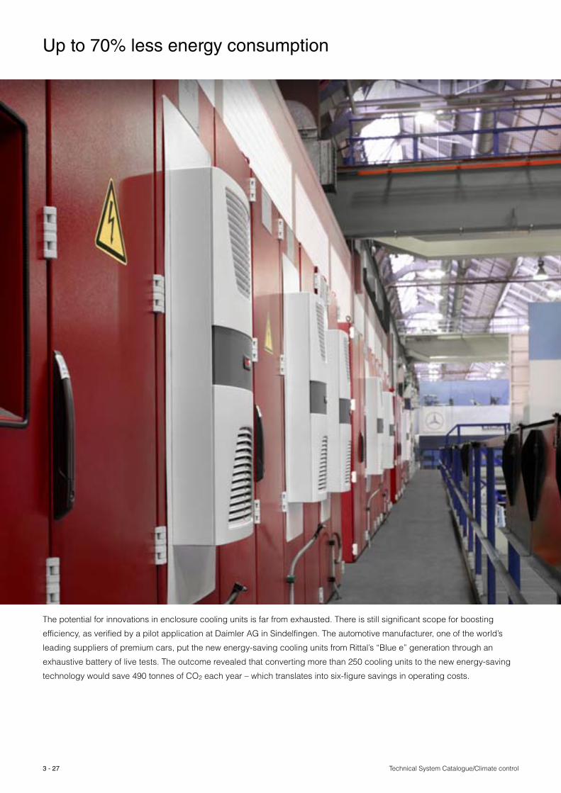
The potential for innovations in enclosure cooling units is far from exhausted. There is still significant scope for boosting
efficiency, as verified by a pilot application at Daimler AG in Sindelfingen. The automotive manufacturer, one of the world’s
leading suppliers of premium cars, put the new energy-saving cooling units from Rittal’s “Blue e” generation through an
exhaustive battery of live tests. The outcome revealed that converting more than 250 cooling units to the new energy-saving
technology would save 490 tonnes of CO2 each year – which translates into six-figure savings in operating costs.
Up to 70% less energy consumption

Technical System Catalogue/Climate control
Wall-mounted cooling units
3 - 28
Project planning Page 17 Therm 6.1 software Page 85 Order information Catalogue 33, from page 415
Benefits at a glance:
� Super-efficient performance and energy consumption
� Wide output range from 300 W to 4000 W
� Controlling and monitoring via Basic or e-Comfort controller
� Three-phase cooling units support multiple voltages as
standard
� Electrical condensate evaporation and RiNano coating
� Uniform, output-based, system-wide mounting
cut-outs, to coordinate with TopTherm air/air heat
exchangers
Please note:
� Air inlet and outlet openings in the internal and
external circuit must not be obstructed by electrical
installations.
Top design and top performance with a host of assembly
benefits. The Rittal platform strategy with system-wide
mounting cut-outs to fit cooling units and air/air heat
exchangers allows easy adaptation to the required cooling
output, even retrospectively.
Generation “Blue e”
Make permanent energy savings
with Rittal cooling units.
See page 26.
Technical System Catalogue/Climate control
Wall-mounted cooling units
3 - 29
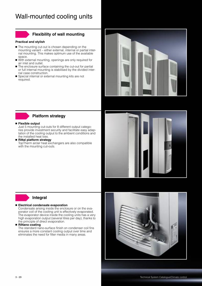
Flexibility of wall mounting
Practical and stylish
� The mounting cut-out is chosen depending on the mounting variant – either external, internal or partial inter-nal mounting. This makes optimum use of the available space.
� With external mounting, openings are only required for air inlet and outlet.
� The enclosure surface containing the cut-out for partial or full internal mounting is stabilised by the divided inter-nal case construction.
� Special internal or external mounting kits are not required.
Platform strategy
� Flexible outputJust 5 mounting cut-outs for 8 different output catego-ries provide investment security and facilitate easy adap-tation of the cooling output to the ambient conditions and the installed heat loss.
� Rittal platform strategyTopTherm air/air heat exchangers are also compatible with the mounting cut-outs.
Integral
� Electrical condensate evaporationCondensate arising inside the enclosure or on the eva-porator coil of the cooling unit is effectively evaporated. The evaporator device inside the cooling units has a very high evaporation output (several litres per day), thanks to the principle of direct evaporation.
� RiNano coatingThe standard nano-surface finish on condenser coil fins ensures a more constant cooling output over time and eliminates the need for filter media in many areas.
Technical System Catalogue/Climate control
Wall-mounted cooling units
3 - 30
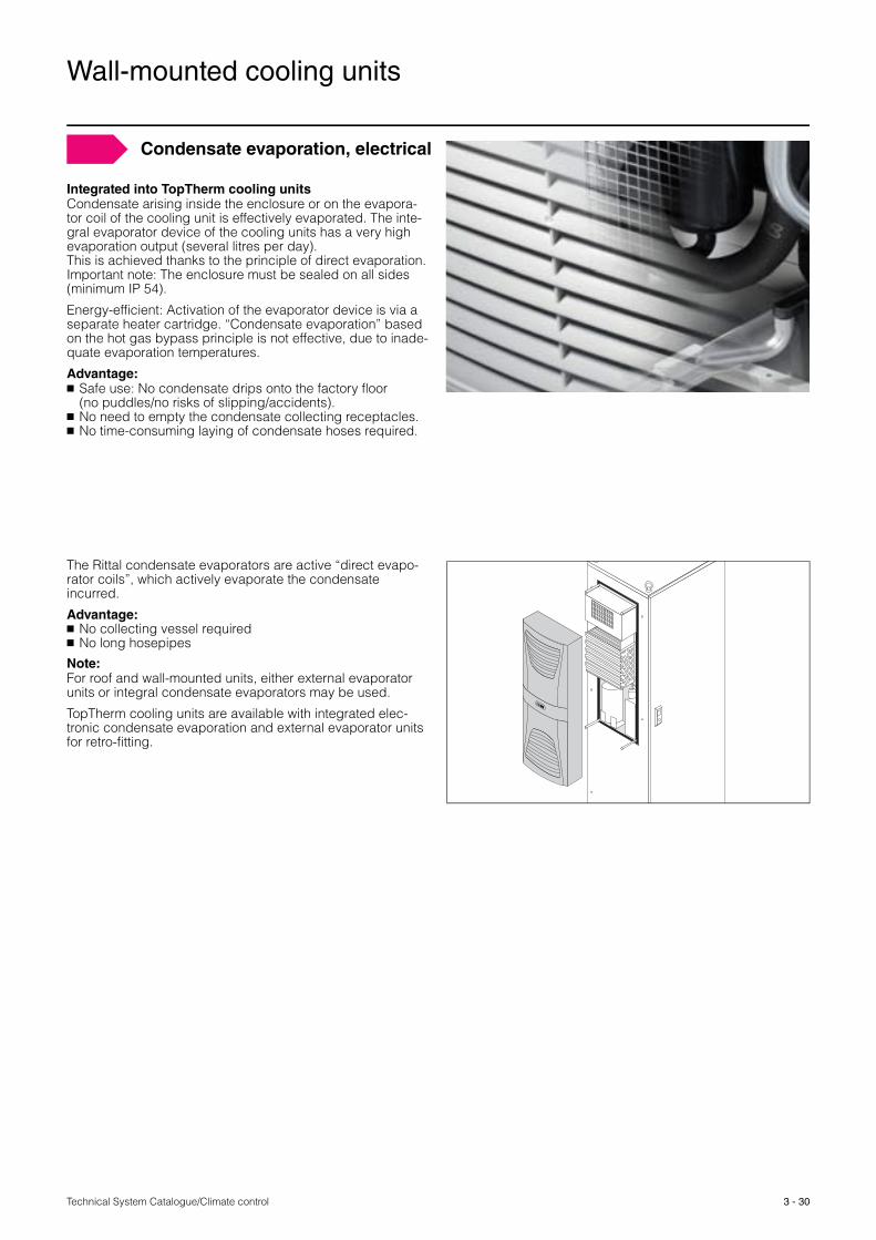
Integrated into TopTherm cooling unitsCondensate arising inside the enclosure or on the evapora-tor coil of the cooling unit is effectively evaporated. The inte-gral evaporator device of the cooling units has a very high evaporation output (several litres per day). This is achieved thanks to the principle of direct evaporation. Important note: The enclosure must be sealed on all sides (minimum IP 54).
Energy-efficient: Activation of the evaporator device is via a separate heater cartridge. “Condensate evaporation” based on the hot gas bypass principle is not effective, due to inade-quate evaporation temperatures.
Advantage: � Safe use: No condensate drips onto the factory floor
(no puddles/no risks of slipping/accidents).� No need to empty the condensate collecting receptacles.� No time-consuming laying of condensate hoses required.
Condensate evaporation, electrical
The Rittal condensate evaporators are active “direct evapo-rator coils”, which actively evaporate the condensate incurred.
Advantage: � No collecting vessel required� No long hosepipes
Note: For roof and wall-mounted units, either external evaporator units or integral condensate evaporators may be used.
TopTherm cooling units are available with integrated elec-tronic condensate evaporation and external evaporator units for retro-fitting.
Technical System Catalogue/Climate control3 - 31
Project planning Page 17 Therm 6.1 software Page 85 Order information Catalogue 33, from page 426
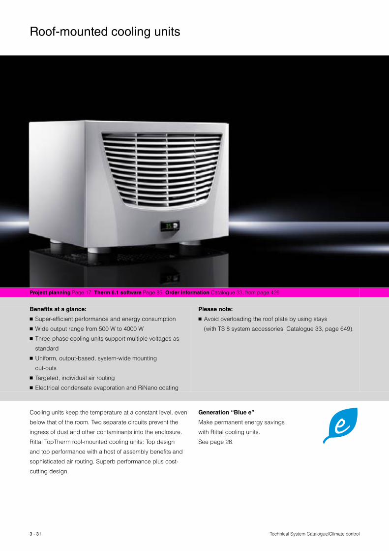
Benefits at a glance:
� Super-efficient performance and energy consumption
� Wide output range from 500 W to 4000 W
� Three-phase cooling units support multiple voltages as
standard
� Uniform, output-based, system-wide mounting
cut-outs
� Targeted, individual air routing
� Electrical condensate evaporation and RiNano coating
Please note:
� Avoid overloading the roof plate by using stays
(with TS 8 system accessories, Catalogue 33, page 649).
Cooling units keep the temperature at a constant level, even
below that of the room. Two separate circuits prevent the
ingress of dust and other contaminants into the enclosure.
Rittal TopTherm roof-mounted cooling units: Top design
and top performance with a host of assembly benefits and
sophisticated air routing. Superb performance plus cost-
cutting design.
Roof-mounted cooling units
Generation “Blue e”
Make permanent energy savings
with Rittal cooling units.
See page 26.

3 - 32Technical System Catalogue/Climate control
Flexibility of roof mounting
� Cut your costsAll three-phase cooling units are suitable for a voltage range of 400/460 V and a frequency range of 50/60 Hz without rewiring. No need for expensive additional trans-formers.
� Flexible performanceJust 3 mounting cut-outs for 6 different output catego-ries provide investment security and facilitate easy adap-tation of the cooling output to the ambient conditions and the installed heat loss.
� Rittal platform strategyTopTherm air/water heat exchangers and roof-mounted fans are also compatible with the mounting cut-outs.
Optimum flow conditions
� Targeted air routing inside the enclosureThe internal air circulation is targeted and effective: The heated air is extracted centrally. Chilled air is dis-charged via up to four spigots positioned in the corners of the base plate and may be routed in a controlled man-ner into the lower enclosure chamber via the optional ducting system. The result is highly effective cooling and the avoidance of air short-circuits. The targeted air circu-lation inside the enclosure via ducts also prevents the creation of hot-spots.
Integrated
� Electrical condensate evaporationCondensate arising inside the enclosure or on the eva-porator coil of the cooling unit is effectively evaporated. The evaporator device inside the cooling units has a very high evaporation output (several litres per day). This is achieved thanks to the principle of direct evaporation.
� RiNano coatingThe standard nano-surface finish on condenser coil fins ensures a more constant cooling output over time and eliminates the need for filter media in many areas.

3 - 33 Technical System Catalogue/Climate control
Roof-mounted cooling units
Any condensation which forms on the evaporator coil (with high humidity and low enclosure interior temperatures) is routed to the right and/or downwards out of the device via a drain in the evaporator tray. For this purpose, a piece of hose should be connected to one of the two condensate nozzles (1 or 2). The drain which is not required should be tightly sealed. The condensate must be able to run off freely. If the condensate is to be drained off over a greater dis-tance, then care must be taken to ensure that the hose is free from kinks and checked for correct drainage. Units with a Comfort controller are additionally equipped with a conden-sate alarm.
Condensate discharge rear
Condensate discharge right
Note:Condensate discharge (wall-mounted units)For wall-mounted units, a hose should be connected to the condensate nozzle on the bottom of the unit.
The condensate discharge should be laid with a gradient, taking care to ensure there are no kinks in the pipe!
y
1 2
y
21
1
2
Condensate routing
Technical System Catalogue/Climate control
Climate control checklist
3 - 34
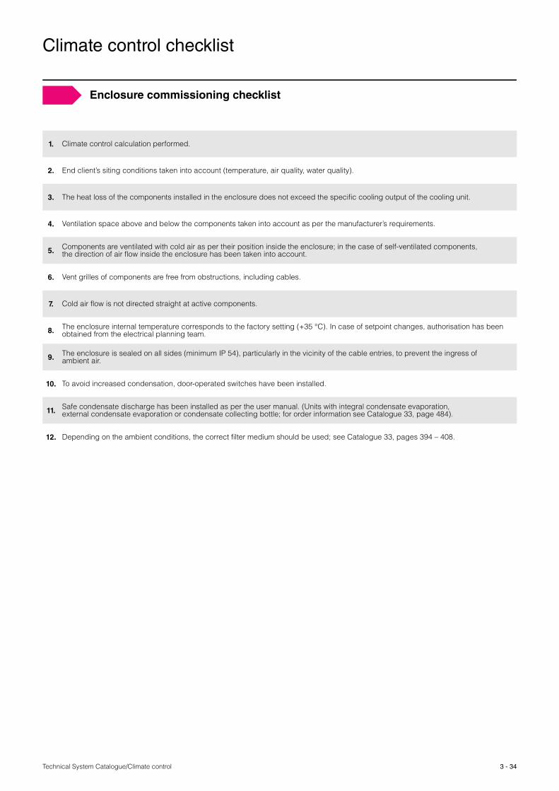
1. Climate control calculation performed.
2. End client’s siting conditions taken into account (temperature, air quality, water quality).
3. The heat loss of the components installed in the enclosure does not exceed the specific cooling output of the cooling unit.
4. Ventilation space above and below the components taken into account as per the manufacturer’s requirements.
5. Components are ventilated with cold air as per their position inside the enclosure; in the case of self-ventilated components, the direction of air flow inside the enclosure has been taken into account.
6. Vent grilles of components are free from obstructions, including cables.
7. Cold air flow is not directed straight at active components.
8. The enclosure internal temperature corresponds to the factory setting (+35 °C). In case of setpoint changes, authorisation has been obtained from the electrical planning team.
9. The enclosure is sealed on all sides (minimum IP 54), particularly in the vicinity of the cable entries, to prevent the ingress of ambient air.
10. To avoid increased condensation, door-operated switches have been installed.
11. Safe condensate discharge has been installed as per the user manual. (Units with integral condensate evaporation, external condensate evaporation or condensate collecting bottle; for order information see Catalogue 33, page 484).
12. Depending on the ambient conditions, the correct filter medium should be used; see Catalogue 33, pages 394 – 408.
Enclosure commissioning checklist
Technical System Catalogue/Climate control
Modular climate control concept
3 - 35
Project planning Page 17 Therm 6.1 software Page 85 Order information Catalogue 33, from page 430
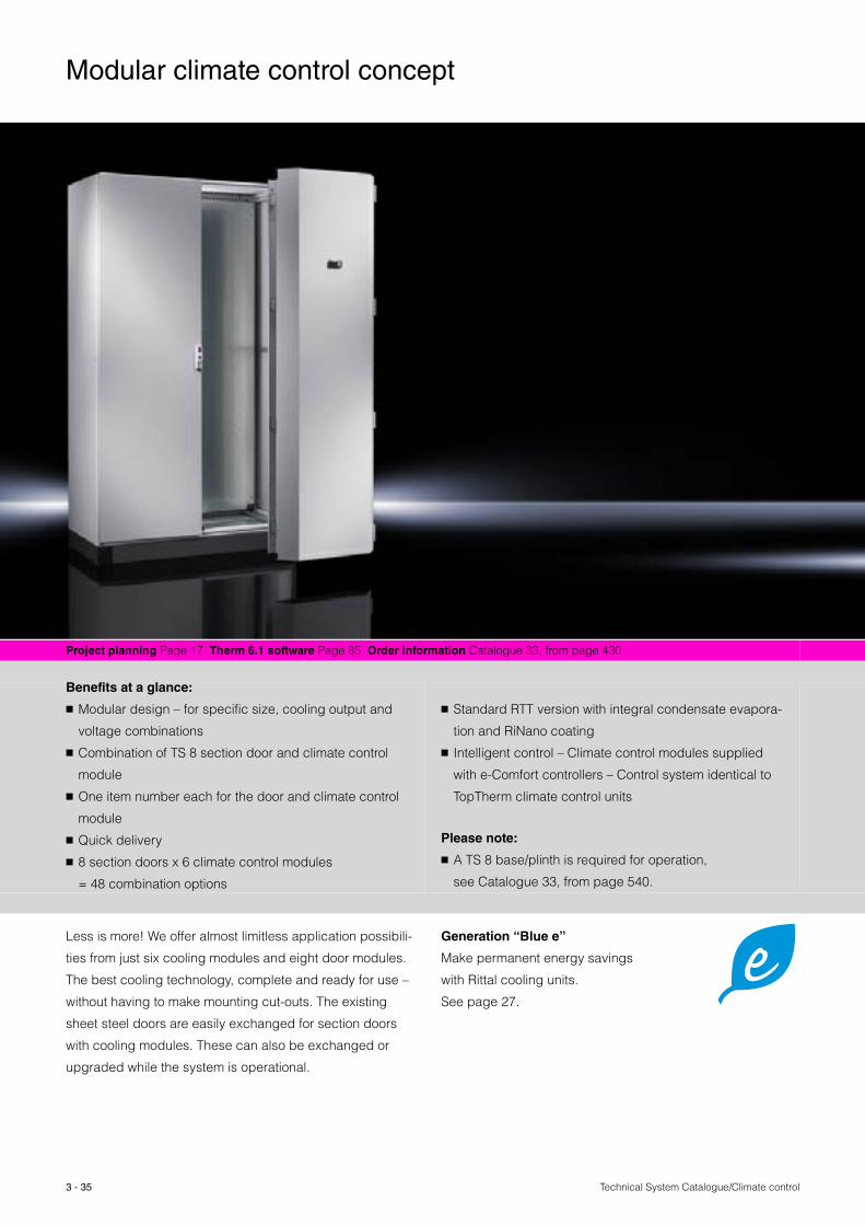
Benefits at a glance:
� Modular design – for specific size, cooling output and
voltage combinations
� Combination of TS 8 section door and climate control
module
� One item number each for the door and climate control
module
� Quick delivery
� 8 section doors x 6 climate control modules
= 48 combination options
� Standard RTT version with integral condensate evapora-
tion and RiNano coating
� Intelligent control – Climate control modules supplied
with e-Comfort controllers – Control system identical to
TopTherm climate control units
Please note:
� A TS 8 base/plinth is required for operation,
see Catalogue 33, from page 540.
Less is more! We offer almost limitless application possibili-
ties from just six cooling modules and eight door modules.
The best cooling technology, complete and ready for use –
without having to make mounting cut-outs. The existing
sheet steel doors are easily exchanged for section doors
with cooling modules. These can also be exchanged or
upgraded while the system is operational.
Generation “Blue e”
Make permanent energy savings
with Rittal cooling units.
See page 27.
3 - 36Technical System Catalogue/Climate control
Modular climate control concept
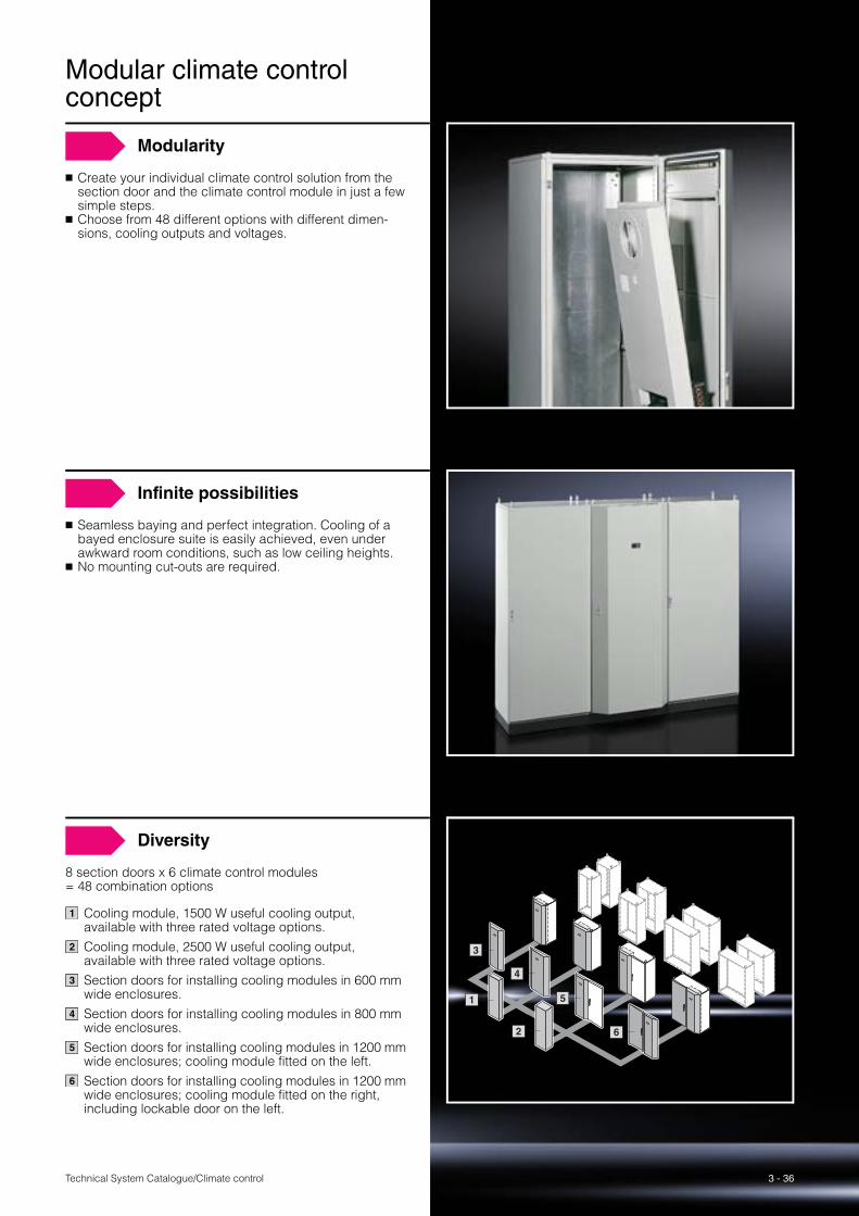
Modularity
� Create your individual climate control solution from the section door and the climate control module in just a few simple steps.
� Choose from 48 different options with different dimen-sions, cooling outputs and voltages.
Infinite possibilities
� Seamless baying and perfect integration. Cooling of a bayed enclosure suite is easily achieved, even under awkward room conditions, such as low ceiling heights.
� No mounting cut-outs are required.
Diversity
8 section doors x 6 climate control modules = 48 combination options
Cooling module, 1500 W useful cooling output, available with three rated voltage options.Cooling module, 2500 W useful cooling output, available with three rated voltage options.Section doors for installing cooling modules in 600 mm wide enclosures.Section doors for installing cooling modules in 800 mm wide enclosures.Section doors for installing cooling modules in 1200 mm wide enclosures; cooling module fitted on the left.Section doors for installing cooling modules in 1200 mm wide enclosures; cooling module fitted on the right, including lockable door on the left.
1
2
3
4
5
6
1
2
3
6
4
5
Technical System Catalogue/Climate control3 - 37
1
3
2
Order information Catalogue 33, from page 433
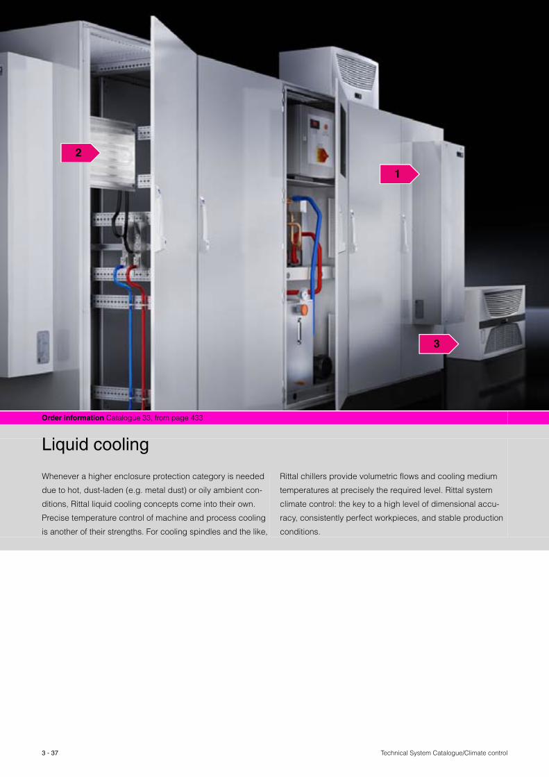
Liquid cooling
Whenever a higher enclosure protection category is needed
due to hot, dust-laden (e.g. metal dust) or oily ambient con-
ditions, Rittal liquid cooling concepts come into their own.
Precise temperature control of machine and process cooling
is another of their strengths. For cooling spindles and the like,
Rittal chillers provide volumetric flows and cooling medium
temperatures at precisely the required level. Rittal system
climate control: the key to a high level of dimensional accu-
racy, consistently perfect workpieces, and stable production
conditions.

3 - 38
Liquid cooling
Technical System Catalogue/Climate control
1 Air/water heat exchanger
Liquid cooling classicsThe temperature of the air inside the enclosure interior may also be cooled to a level below that of the external air by using air/water heat exchangers in conjunction with a cen-tral re-cooling system. Dust is unable to penetrate the enclosure. The waste heat from the enclosure does not raise the tem-perature of the ambient air, provided the cold water supply system is remotely located.
� For extremely hot and dusty ambient conditions� To dissipate high heat loads without putting thermal
pressure on the ambient air
2 Cold Plate
Direct cooling of power electronics inside the enclosureLiquid-cooled partial mounting plate with copper or stain-less steel pipes press-fitted onto the rear, integrated into closed recooling systems or into the existing water infra-structure. With the pitch of Rittal partial mounting plates, installation into the TS 8 top enclosure system is child’s play using system accessories with a 25 mm pitch pattern. At the same time, however, a 4-point attachment facility permits direct mounting on the mounting plate or any other surface.
� Using liquid-cooled mounting plates (Cold Plate) � No impairment to the protection category� With efficient frequency converter cooling
3 Chillers for water
Energy-efficient cooling of liquid cooling mediaChiller systems are a centralised, efficient means of provid-ing cooling either directly or via complementary equip-ment using a fluid medium, typically a mixture of water and gycol. For example, all cooling requirements on a system or machine, whether they are for the process or control equipment, may be satisfied using a single scheme. The spatial seperation of the cooling supply and the process to be cooled may be achieved using a chiller.
� A high level of temperature accuracy� Powerful performance� Individual system solutions

Technical System Catalogue/Climate control
Air/water heat exchanger
3 - 39
Project planning Page 43 Therm 6.1 software Page 85 Order information Catalogue 33, from page 434
Benefits at a glance:
� Useful cooling output from 300 W to 7000 W
� Suitable for use even under extreme conditions and
ambient temperatures of up to +70 °C
� Also available with all water-carrying parts made from
stainless steel
� High protection category. Thanks to the sealed design,
a protection category of IP 55 to EN 60 529 is achieved.
Please note:
Air/water heat exchangers should always be used in con-
junction with recooling systems or an existing cooling water
circuit.
The temperature of the air inside the enclosure may also be
cooled to a level below that of the external air, if required,
using cooled water from a central recooling system. The
ingress of dust from outside into the cooled enclosure is
prevented. The waste heat from the enclosure does not raise
the temperature of the ambient air, provided the heat
exchanger and cold water supply system are located remote
to one another.
Air/water heat exchangers may even be used in particularly
extreme ambient temperatures from +1 °C to +70 °C.
Even extreme levels of contamination in the ambient air,
e.g. with dust and oil, do not affect functionality. High heat
losses are dissipated in the most confined spaces without
emitting them directly to the ambient air. High cooling per-
formances are achieved, thanks to the large surface area of
the heat exchanger unit and the powerful fan technology.

3 - 40Technical System Catalogue/Climate control
Air/water heat exchanger
Variants
� Roof mountingEspecially for bayed enclosures, where wall-mounted devices would obstruct the door.
� Wall mountingFor mounting on the wall or any sufficiently large vertical surface.
More effective cooling thanks to selective air routingAn important feature of TopTherm roof-mounted units: The air cooled by the heat exchanger is routed precisely to the relevant assembly via the air duct system, see Catalogue 33, page 473.
The result:Exceptionally efficient and cost-effective cooling!
Another cost benefit:The air duct system is also compatible with roof-mounted cooling units.
Flexibility
Versatile water connection optionsSafe connection technology thanks to a certified system:
� The new threaded adaptors for quick fastening allow easy connection to fixed or flexible piping; see Catalogue 33, page 486.
� Flex-hose and connector/coupling are included as standard with the supply – G3/8˝ internal or external threads are also optionally available.
Functional reliability
Enhanced functional reliability and longevityCorrosion can be prevented, as the heat exchangers are also available with all water-carrying parts in stainless steel (V4A 1.4571).
Wide output range
� From 300 W to 7000 W useful cooling capacity for every application
� Simple assembly with roof-mounted and wall-mounted cooling units
Available immediately in 230 VAll outputs are also available in 115 and 400 V in our standard special range.
Technical System Catalogue/Climate control
Air/water heat exchanger
3 - 41
Cooling units Page 15 Air/air heat exchangers Page 11
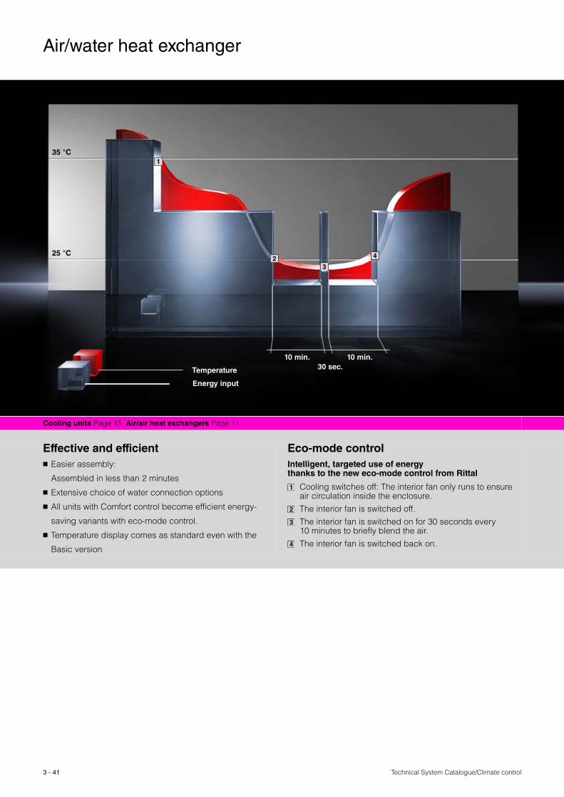
Effective and efficient � Easier assembly:
Assembled in less than 2 minutes
� Extensive choice of water connection options
� All units with Comfort control become efficient energy-
saving variants with eco-mode control.
� Temperature display comes as standard even with the
Basic version
Eco-mode controlIntelligent, targeted use of energy thanks to the new eco-mode control from Rittal
Cooling switches off: The interior fan only runs to ensure air circulation inside the enclosure.The interior fan is switched off.The interior fan is switched on for 30 seconds every 10 minutes to briefly blend the air. The interior fan is switched back on.
1
2
3
4
35 °C
25 °C
Temperature
Energy input
1
2 3
4
10 min. 10 min.30 sec.
Technical System Catalogue/Climate control
Air/water heat exchanger
3 - 42
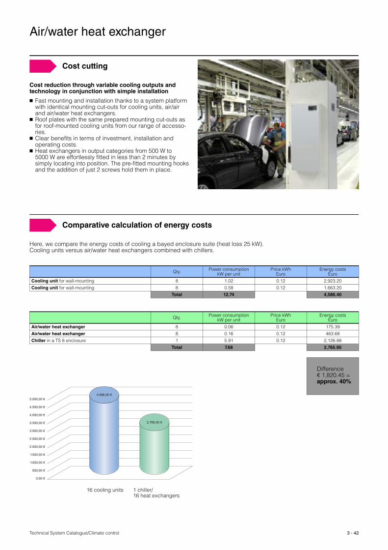
Cost cutting
Cost reduction through variable cooling outputs and technology in conjunction with simple installation
� Fast mounting and installation thanks to a system platform with identical mounting cut-outs for cooling units, air/air and air/water heat exchangers.
� Roof plates with the same prepared mounting cut-outs as for roof-mounted cooling units from our range of accesso-ries.
� Clear benefits in terms of investment, installation and operating costs.
� Heat exchangers in output categories from 500 W to 5000 W are effortlessly fitted in less than 2 minutes by simply locating into position. The pre-fitted mounting hooks and the addition of just 2 screws hold them in place.
5.000,00 €
4.500,00 €
4.000,00 €
3.500,00 €
3.000,00 €
2.500,00 €
2.000,00 €
1.500,00 €
1.000,00 €
500,00 €
0,00 €
4.586,00 €
2.766,00 €
Comparative calculation of energy costs
Here, we compare the energy costs of cooling a bayed enclosure suite (heat loss 25 kW).Cooling units versus air/water heat exchangers combined with chillers.
Qty. Power consumptionkW per unit
Price kWhEuro
Energy costsEuro
Cooling unit for wall-mounting 8 1.02 0.12 2,923.20Cooling unit for wall-mounting 8 0.58 0.12 1,663.20
Total 12.74 4,586.40
Qty. Power consumptionkW per unit
Price kWhEuro
Energy costsEuro
Air/water heat exchanger 8 0.06 0.12 175.39Air/water heat exchanger 8 0.16 0.12 463.68Chiller in a TS 8 enclosure 1 5.91 0.12 2,126.88
Total 7.68 2,765.95
Difference € 1,820.45 = approx. 40%
16 cooling units 1 chiller/16 heat exchangers
3 - 43 Technical System Catalogue/Climate control
Air/water heat exchanger
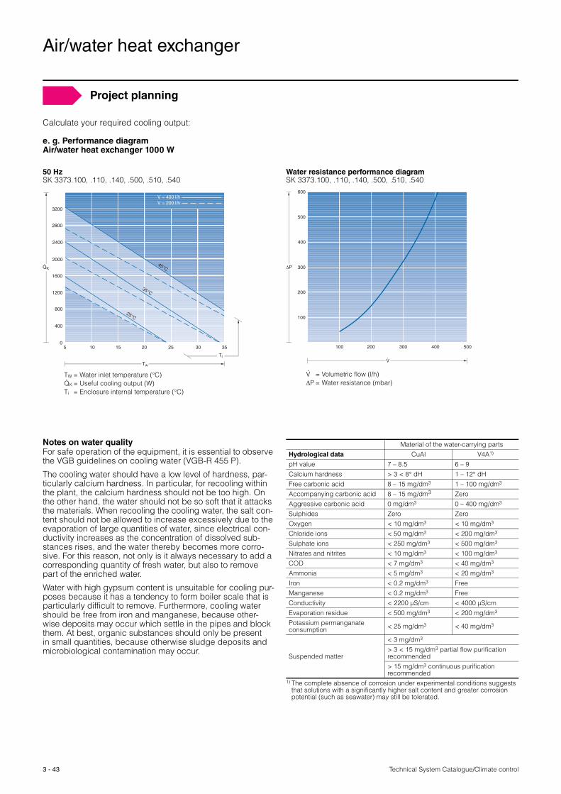
Project planning
Calculate your required cooling output:
e. g. Performance diagram Air/water heat exchanger 1000 W
Notes on water qualityFor safe operation of the equipment, it is essential to observe the VGB guidelines on cooling water (VGB-R 455 P).
The cooling water should have a low level of hardness, par-ticularly calcium hardness. In particular, for recooling within the plant, the calcium hardness should not be too high. On the other hand, the water should not be so soft that it attacks the materials. When recooling the cooling water, the salt con-tent should not be allowed to increase excessively due to the evaporation of large quantities of water, since electrical con-ductivity increases as the concentration of dissolved sub-stances rises, and the water thereby becomes more corro-sive. For this reason, not only is it always necessary to add a corresponding quantity of fresh water, but also to remove part of the enriched water.
Water with high gypsum content is unsuitable for cooling pur-poses because it has a tendency to form boiler scale that is particularly difficult to remove. Furthermore, cooling water should be free from iron and manganese, because other-wise deposits may occur which settle in the pipes and block them. At best, organic substances should only be present in small quantities, because otherwise sludge deposits and microbiological contamination may occur.
Material of the water-carrying parts Hydrological data CuAl V4A1) pH value 7 – 8.5 6 – 9Calcium hardness > 3 < 8° dH 1 – 12° dHFree carbonic acid 8 – 15 mg/dm3 1 – 100 mg/dm3 Accompanying carbonic acid 8 – 15 mg/dm3 ZeroAggressive carbonic acid 0 mg/dm3 0 – 400 mg/dm3 Sulphides Zero ZeroOxygen < 10 mg/dm3 < 10 mg/dm3 Chloride ions < 50 mg/dm3 < 200 mg/dm3 Sulphate ions < 250 mg/dm3 < 500 mg/dm3 Nitrates and nitrites < 10 mg/dm3 < 100 mg/dm3 COD < 7 mg/dm3 < 40 mg/dm3 Ammonia < 5 mg/dm3 < 20 mg/dm3 Iron < 0.2 mg/dm3 FreeManganese < 0.2 mg/dm3 FreeConductivity < 2200 μS/cm < 4000 μS/cmEvaporation residue < 500 mg/dm3 < 200 mg/dm3 Potassium permanganate consumption < 25 mg/dm3 < 40 mg/dm3
Suspended matter
< 3 mg/dm3 > 3 < 15 mg/dm3 partial flow purificationrecommended> 15 mg/dm3 continuous purification recommended
1) The complete absence of corrosion under experimental conditions suggests that solutions with a significantly higher salt content and greater corrosionpotential (such as seawater) may still be tolerated.
50 HzSK 3373.100, .110, .140, .500, .510, .540
2800
3200
2400
2000
1600
1200
800
400
05 10 15 20 25 30 35
Tw
QK.
25°C
35°C
45°C
Ti
V = 400 l/hV = 200 l/h
TW = Water inlet temperature (°C)QK = Useful cooling output (W)Ti = Enclosure internal temperature (°C)
.
Water resistance performance diagramSK 3373.100, .110, .140, .500, .510, .540
600
500
400
300
100
200
100 200 300 400 500
ΔP
V.
V = Volumetric flow (l/h)ΔP = Water resistance (mbar)
.
Technical System Catalogue/Climate control
Air/water heat exchanger
3 - 44
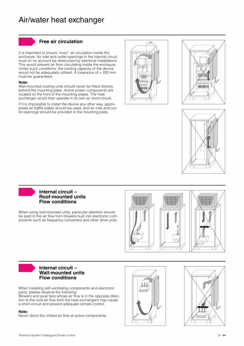
It is important to ensure “even” air circulation inside the enclosure. Air inlet and outlet openings in the internal circuit must on no account be obstructed by electrical installations. This would prevent air from circulating inside the enclosure. Under such conditions, the cooling capacity of the device would not be adequately utilised. A clearance of > 200 mm must be guaranteed.
Note:Wall-mounted cooling units should never be fitted directly behind the mounting plate. Active power components are located on the front of the mounting plates. The heat exchanger would then operate in its own air short-circuit.
If it is impossible to install the device any other way, appro-priate air baffle plates should be used, and air inlet and out-let openings should be provided in the mounting plate.
200Free air circulation
When using roof-mounted units, particular attention should be paid to the air flow from blowers built into electronic com-ponents such as frequency converters and other drive units.
Internal circuit – Roof-mounted unitsFlow conditions
When installing self-ventilating components and electronic parts, please observe the following: Blowers and axial fans whose air flow is in the opposite direc-tion to the cold air flow from the heat exchangers may cause a short-circuit and prevent adequate climate control.
Note:Never direct the chilled air flow at active components.
Internal circuit – Wall-mounted unitsFlow conditions
3 - 45 Technical System Catalogue/Climate control
Air/water heat exchanger
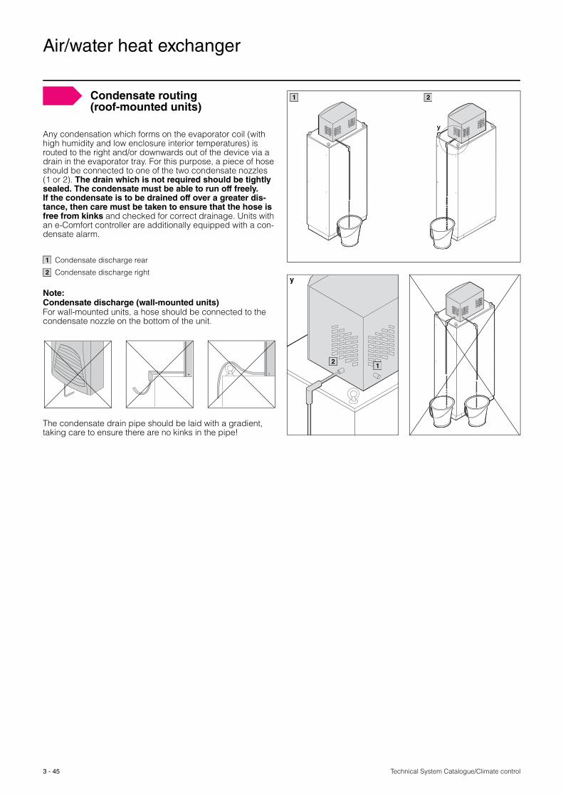
Condensate routing (roof-mounted units)
Any condensation which forms on the evaporator coil (with high humidity and low enclosure interior temperatures) is routed to the right and/or downwards out of the device via a drain in the evaporator tray. For this purpose, a piece of hose should be connected to one of the two condensate nozzles (1 or 2). The drain which is not required should be tightly sealed. The condensate must be able to run off freely. If the condensate is to be drained off over a greater dis-tance, then care must be taken to ensure that the hose is free from kinks and checked for correct drainage. Units with an e-Comfort controller are additionally equipped with a con-densate alarm.
Condensate discharge rear
Condensate discharge right
Note:Condensate discharge (wall-mounted units)For wall-mounted units, a hose should be connected to the condensate nozzle on the bottom of the unit.
The condensate drain pipe should be laid with a gradient, taking care to ensure there are no kinks in the pipe!
y
1 2
y
21
1
2

Technical System Catalogue/Climate control
Air/water heat exchanger
3 - 46
The two controller variants for operational reliability offer a comprehensive range of functions. Essential control elec-tronics are well protected and cooled in the inner circuit.
Both variants have the following properties: � Three voltage options: 115 V, 230 V, 400/460 V, 3 ˜ � Integral start-up delay and door limit switch function � Icing protection function� Monitoring of all motors� Phase monitoring for three-phase units
Basic controller: � Visualisation of the operating status via LED display:− Voltage applied, functions OK− Door open− Overtemperature− High-pressure monitor has switched
� Switching hysteresis: 5 K� Floating fault signal contact in case of overtemperature� Setpoint adjustable from outside via potentiometer
(setting range 20 – 55 °C)
Intelligent control
e-Comfort controller:
� Master/slave function for up to 10 units, i.e. the unit which reaches the setpoint first reports this to the “master unit” which switches all other “slave units” on and off. The unit which activates the door limit switch function reports this to the “master unit”, which switches off all “slave units”.
� Switching hysteresis: 2 – 10 K; preset to 5 K� System alarm, individually configurable for 2 floating fault
signal contacts� Visualisation of the current enclosure internal temperature
and all system messages on the display� Storage of all system statuses in the log file� Optional interface card (SK 3124.200) with RS-232,
RS-485, RS-422 and PLC interface for integration into superordinate remote control systems, e.g. with CMC, is also possible

Technical System Catalogue/Climate control
Cold Plate
3 - 47
Order information Catalogue 33, page 444
Benefits at a glance:
� High surface quality (Ra = 1.2 μm) to reduce thermal
resistance
� No vibrations from compressors and fans
� Ideal for precision machine tools
� No noise generation
� No top-mounted parts on the enclosure
� Enclosure may be installed in the machine base
and in niches
� The protection category of the enclosure is preserved
� Mounting surface on both sides may be used as a contact
surface for heat dissipation
� Space-saving configuration of electronic components in
the enclosure
Please note:
� Two standard versions with water-carrying parts made
of copper or stainless steel are available from stock
� Manufacturer or customer-specific Cold Plates may
be supplied on a project-related basis on request.
Power electronic components can be cooled particularly
effectively using the liquid cooled DCP mounting plate. Heat
losses are cleverly dissipated from the enclosure or housing
without compromising the high enclosure protection cate-
gory in any way. Liquid cooling is silent, as well as being
many times more efficient than heat loss dissipation via air.
The horizontal positioning of the water pipes ensures even
heat dissipation and allows easy emptying.
Copper piping: For standard applications with air/water heat
exchangers and recooling systems with the cooling medium
water + glycol (e. g. inhibitor Antifrogen N 20 – 30 vol. %).
Stainless steel piping: Material 1.4301 e.g. for open cooling
circuits and for use in the food industry.
The Rittal DCP Cold Plate has received type-tested certification from the TÜV inspection authority and is approved for pressures up to 10 bar.
y p e Te s te

3 - 48Technical System Catalogue/Climate control
Cold Plate
Assembly
� Height and depth-variable mounting positions are offered by the system punchings of the TS 8 profiles in con-junction with punched section with mounting flange 17 x 73 mm (for the outer mounting level).
� Medium connections on the sides provide a larger plate capacity, and allow easier draining.
Attachment directly in the T-slot
Direct and fast mounting using sliding nuts for components with suitable dimensions. Direct earthing or equipotential bonding points may be provided on the Cold Plate.
Attachment with variable clamping system
Supports fast mechanical installation without the need for drilling, independently of the original attachment points on the component. For use with a wide range of models and makes.
Attachment with retainers
Frequency converters with dimensions marginally smaller than the T-slot spacing can be secured with special retain-ers.
Attachment with tapped holes
Power electronics may be attached on both sides of the entire surface using tapped holes (except where the copper pipelines are laid, as shown on the drawing).

Technical System Catalogue/Climate control
Chillers for water
3 - 49
Project planning Page 51 Therm 6.1 software Page 85 Order information Catalogue 33, from page 446
Benefits at a glance:
� Cooling output from 1 kW to 40 kW
� One system for enclosure cooling
� Integration into bayed enclosure suites
� Individual project planning
� Commissioning and servicing
� Comprehensive pipeline calculation
� Global service network
Applications:
� Enclosure cooling
� Cooling of liquid media
� Process and machine cooling
� Spindle cooling
� IT server cooling
Chiller systems are a centralised and efficient means of
providing cooling either directly or via complementary equip-
ment using a fluid medium, typically a mixture of water and
glycol, and may be used to dissipate particularly high heat
loads.
For example, all cooling requirements on a system or
machine, whether they are for the process or the control
equipment, may be satisfied using a single scheme. The
spatial separation of the cooling supply and the process
to be cooled may be achieved using a chiller which may
supply several pieces of equipment simultaneously, and is
particularly effective in terms of cooling output.
3 - 50Technical System Catalogue/Climate control
Chillers for water
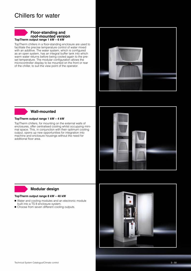
Floor-standing and roof-mounted version
TopTherm output range 1 kW – 6 kW
TopTherm chillers in a floor-standing enclosure are used to facilitate the precise temperature control of water mixed with an additive. The water system, which is configured as an open system, has an integral buffer tank into which warm water returns before being cooled again to the pre-set temperature. The modular configuration allows the microcontroller display to be mounted on the front or rear of the chiller, to suit the view point of the operator.
Wall-mounted
TopTherm output range 1 kW – 4 kW
TopTherm chillers, for mounting on the external walls of enclosures, offer centralised cooling whilst occupying mini-mal space. This, in conjunction with their optimum cooling output, opens up new opportunities for integration into machine and enclosure housings without the need for additional floor area.
Modular design
TopTherm output range 8 kW – 40 kW
� Water and cooling modules and an electronic module built into a TS 8 enclosure system.
� Choose from seven different cooling outputs.
3 - 51 Technical System Catalogue/Climate control
Chillers for water
Project planning
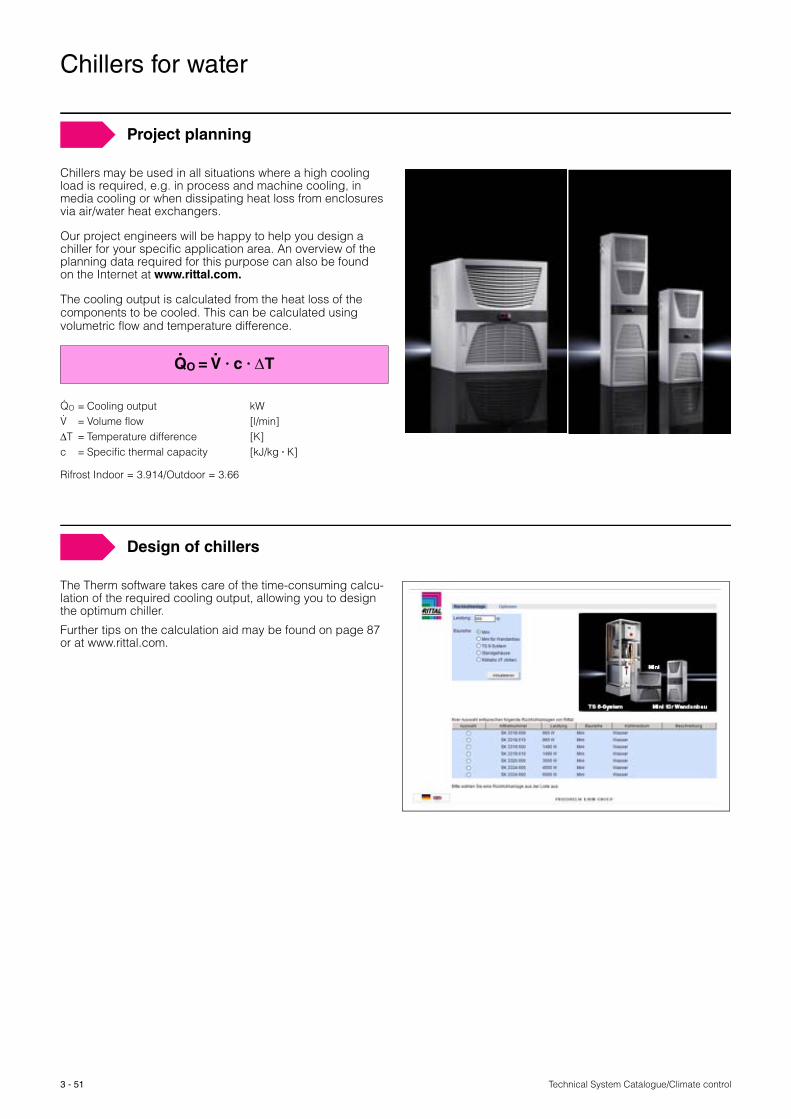
Chillers may be used in all situations where a high cooling load is required, e.g. in process and machine cooling, in media cooling or when dissipating heat loss from enclosures via air/water heat exchangers.
Our project engineers will be happy to help you design a chiller for your specific application area. An overview of the planning data required for this purpose can also be found on the Internet at www.rittal.com.
The cooling output is calculated from the heat loss of the components to be cooled. This can be calculated using volumetric flow and temperature difference.
QO = V � c � ΔT
QO = Cooling output kWV = Volume flow [l/min]ΔT = Temperature difference [K]c = Specific thermal capacity [kJ/kg � K]
Rifrost Indoor = 3.914/Outdoor = 3.66
. .
..
Design of chillers
The Therm software takes care of the time-consuming calcu-lation of the required cooling output, allowing you to design the optimum chiller.
Further tips on the calculation aid may be found on page 87 or at www.rittal.com.

Technical System Catalogue/Climate control
Chillers – General instructions
3 - 52
Assembly and commissioning
When siting the chillers, the following points should be observed:
� Connection of an inlet and outlet duct requires the manu-facturer’s prior consent. − Performance loss (air-cooled chillers)
� Never site the chiller in the vicinity of a heater.− Performance loss.
� The chiller may only be sited on flat, solid surfaces. The maximum permissible deviation from the vertical is 2°.
� Connect the equipment to the chiller using insulated pipe or hose connections.
� If the equipment is positioned higher than the chiller, install a non-return valve in the upstream inlet and a mag-netic valve in the return to prevent the tank from overflow-ing.
� With chillers that are intended for covered outdoor siting, the minimum external temperature should be taken from the technical specifications.
� In the case of chillers (for water) at temperatures below 0 °C, a water/glycol mixture should be added in the pre-scribed ratio.
� If it is possible to shut off the equipment cycle, a bypass must be provided in order to protect the pump.
� Under no circumstances must the circulation pump be allowed to run dry.− Damage to the pump.
Distance from equipment
Site the chiller close to the equipment it is supplying in order to avoid long pipe runs which may lead to a reduction in cooling output due to unsuitable ambient conditions. When selecting the installation site, care should be taken to ensure easy access at all times; this will make maintenance of the system easier.
You should also ensure adequate ventilation of the room where the chiller is sited. If there is inadequate ventilation, the temperature of the room will increase as a result of waste heat, leading to impaired performance of the chillers.
Cooling media
Chillers are suitable for cooling water or a water/glycol mix-ture. When filling the systems for the first time, water from the existing supply line is generally suitable, although care should be taken to ensure a consistent water quality.
However, as satisfactory results are only rarely achieved without water treatment, additives should always be added to the cooling water, irrespective of the installation site. As well as protecting against frost, these also serve to impair bacterial growth and achieve optimum corrosion protection.
Pre-mixed additive is available from Rittal in the mix ratios
� 1:2 for outdoor siting� 1:4 for indoor siting, both types are available in 10 l, 25 l
and 200 l containers
Technical System Catalogue/Climate control3 - 53
Therm 6.1 software Page 85 Order information Catalogue 33, from page 446 – 451
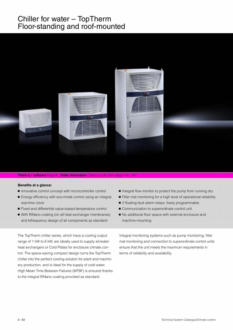
Benefits at a glance:
� Innovative control concept with microcontroller control
� Energy efficiency with eco-mode control using an integral
real-time clock
� Fixed and differential-value-based temperature control
� With RiNano coating (on all heat exchanger membranes)
and bifrequency design of all components as standard
� Integral flow monitor to protect the pump from running dry
� Filter mat monitoring for a high level of operational reliability
� 2 floating fault alarm relays, freely programmable
� Communication to superordinate control unit
� No additional floor space with external enclosure and
machine mounting
The TopTherm chiller series, which have a cooling output
range of 1 kW to 6 kW, are ideally used to supply air/water
heat exchangers or Cold Plates for enclosure climate con-
trol. The space-saving compact design turns the TopTherm
chiller into the perfect cooling solution for plant and machin-
ery production, and is ideal for the supply of cold water.
High Mean Time Between Failures (MTBF) is ensured thanks
to the integral RiNano coating provided as standard.
Integral monitoring systems such as pump monitoring, filter
mat monitoring and connection to superordinate control units
ensure that the unit meets the maximum requirements in
terms of reliability and availability.
Chiller for water – TopTherm Floor-standing and roof-mounted
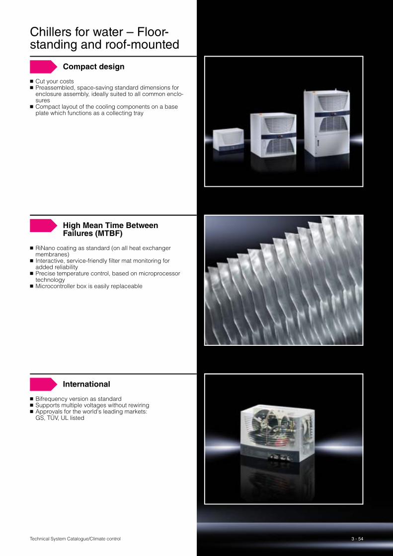
3 - 54Technical System Catalogue/Climate control
Compact design
� Cut your costs� Preassembled, space-saving standard dimensions for
enclosure assembly, ideally suited to all common enclo-sures
� Compact layout of the cooling components on a base plate which functions as a collecting tray
High Mean Time Between Failures (MTBF)
� RiNano coating as standard (on all heat exchanger membranes)
� Interactive, service-friendly filter mat monitoring for added reliability
� Precise temperature control, based on microprocessor technology
� Microcontroller box is easily replaceable
International
� Bifrequency version as standard� Supports multiple voltages without rewiring� Approvals for the world's leading markets:
GS, TÜV, UL listed
Chillers for water – Floor-standing and roof-mounted

Technical System Catalogue/Climate control3 - 55
Therm 6.1 software Page 85 Order information Catalogue 33, from page 448
Benefits at a glance:
� Modular layout for enclosure assembly, partial assembly
and full installation
� Integral flow monitor to protect the pump from running
dry
� No additional floor space with external enclosure and
machine mounting
� System messages are displayed centrally
The TopTherm chiller series, which have a cooling output
range of 1 kW to 4 kW, are ideally used to supply air/water
heat exchangers or Cold Plates for enclosure climate con-
trol. The space-saving compact design turns the TopTherm
chiller into the perfect cooling solution for plant and machin-
ery production, and is ideal for the supply of cold water.
High Mean Time Between Failures (MTBF) is ensured thanks
to the integral RiNano coating provided as standard.
Integral monitoring systems such as pump monitoring, filter
mat monitoring and connection to superordinate control units
ensure that the unit meets the maximum requirements in
terms of reliability and availability.
Chillers for water – TopTherm wall-mounted
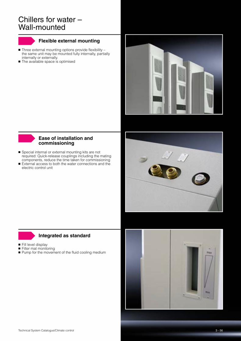
3 - 56Technical System Catalogue/Climate control
Flexible external mounting
� Three external mounting options provide flexibility – the same unit may be mounted fully internally, partially internally or externally.
� The available space is optimised
Ease of installation and commissioning
� Special internal or external mounting kits are not required: Quick-release couplings including the mating components, reduce the time taken for commissioning
� External access to both the water connections and the electric control unit
Integrated as standard
� Fill level display� Filter mat monitoring� Pump for the movement of the fluid cooling medium
Chillers for water – Wall-mounted

Technical System Catalogue/Climate control3 - 57
Therm 6.1 software Page 85 Order information Catalogue 33, page 449
Benefits at a glance:
Premanufactured standard modules
� Shorter delivery times (modular design)
� Integration into TS 8 system
� Global 24-hour service availability and reduced number
of spare parts
High standard specification
� High reliability thanks to the supply of an automatic water
bypass valve and flow switch as standard
� More efficient refrigerant R410A
Greater flexibility
� Output range: 8 kW – 40 kW
� Small footprint thanks to vertical design
� One version for two frequencies
providing international compatibility
Chillers have proved ideal for powerful, targeted climate
control in industry. The new TopTherm chiller from Rittal is a
particular highlight since the modular chiller covers eight
cooling outputs ranging from 8 kW to 40 kW with five sizes.
This translates into savings across the board, since rather
than customised production, the new TopTherm chiller is a
standardised climate control solution with a full performance
range available off the shelf.
Well thought-out: TopTherm chillers based on the TS 8 enclo-
sure integrate the electrical controller as well as the water
and cooling module, and spare parts management is
reduced to a bare minimum.
Chillers for water – Modular design

3 - 58Technical System Catalogue/Climate control
Modular design
Control module
� One version for two frequencies 400 V/50 Hz, 460 V/60 Hz
� Temperature control using fixed or differential values, switchable
Chiller module
� Various air inlet options enable the chiller to be specifi-cally tailored to cater for any site restrictions. Air inlet may be from the rear (size 8, 12 and 16 kW), or option-ally from the left or right.
� Refrigerant R410A� Modules with different outputs may be easily exchanged
Water module
� Water bypass valve supplied as standard� Flow switch supplied as standard� Modules with different outputs may be easily exchanged
Enclosure suites
� Two modules can be bayed together to double the cooling capacity
� Integration into existing enclosure suites is possible.
Chillers for water –

3 - 59 Technical System Catalogue/Climate control
Chiller for water – Modular design
5.000,00 €
4.500,00 €
4.000,00 €
3.500,00 €
3.000,00 €
2.500,00 €
2.000,00 €
1.500,00 €
1.000,00 €
500,00 €
0,00 €
4.586,00 €
2.766,00 €
Here, we compare the energy costs of cooling a bayed enclosure suite (heat loss 25 kW).Cooling units versus air/water heat exchangers combined with chillers.
Comparative calculation of energy costs
Qty. Power consumptionkW per unit
Price kWhEuro
Energy costsEuro
Cooling unit for wall-mounting 8 1.02 0.12 2,923.20Cooling unit for wall-mounting 8 0.58 0.12 1,663.20
Total 12.74 4,586.40
Qty. Power consumptionkW per unit
Price kWhEuro
Energy costsEuro
Air/water heat exchanger 8 0.06 0.12 175.39Air/water heat exchanger 8 0.16 0.12 463.68Chiller in a TS 8 enclosure 1 5.91 0.12 2,126.88
Total 7.68 2,765.95
Difference € 1,820.45 = approx. 40%
16 cooling units 1 chiller/16 heat exchangers
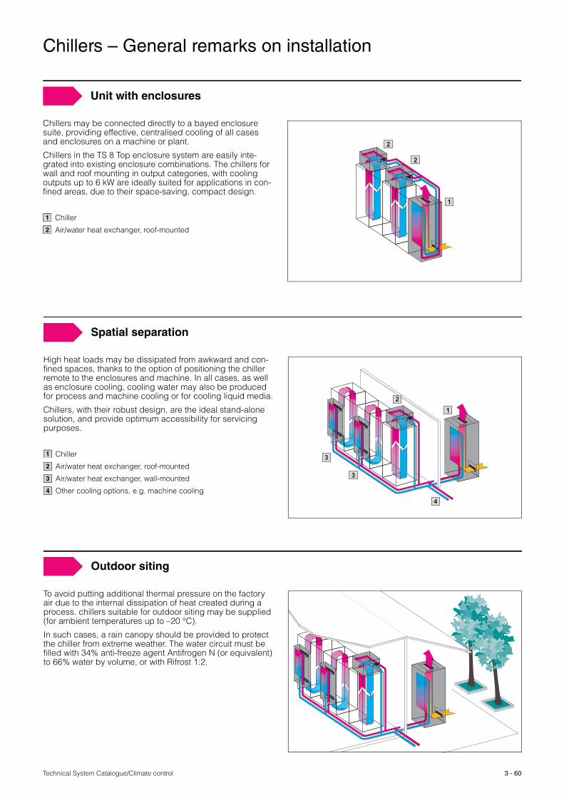
Technical System Catalogue/Climate control
Chillers – General remarks on installation
3 - 60
Unit with enclosures
Chillers may be connected directly to a bayed enclosure suite, providing effective, centralised cooling of all cases and enclosures on a machine or plant.
Chillers in the TS 8 Top enclosure system are easily inte-grated into existing enclosure combinations. The chillers for wall and roof mounting in output categories, with cooling outputs up to 6 kW are ideally suited for applications in con-fined areas, due to their space-saving, compact design.
Chiller
Air/water heat exchanger, roof-mounted
1
2
2
1
2
Spatial separation
High heat loads may be dissipated from awkward and con-fined spaces, thanks to the option of positioning the chiller remote to the enclosures and machine. In all cases, as well as enclosure cooling, cooling water may also be produced for process and machine cooling or for cooling liquid media.
Chillers, with their robust design, are the ideal stand-alone solution, and provide optimum accessibility for servicing purposes.
Chiller
Air/water heat exchanger, roof-mounted
Air/water heat exchanger, wall-mounted
Other cooling options, e.g. machine cooling
12
3
3
4
1
2
3
4
Outdoor siting
To avoid putting additional thermal pressure on the factory air due to the internal dissipation of heat created during a process. chillers suitable for outdoor siting may be supplied (for ambient temperatures up to –20 °C).
In such cases, a rain canopy should be provided to protect the chiller from extreme weather. The water circuit must be filled with 34% anti-freeze agent Antifrogen N (or equivalent) to 66% water by volume, or with Rifrost 1:2.

Technical System Catalogue/Climate control3 - 61
Order information Catalogue 33, from page 456
Aisle containment
In server rooms that have not been designed as data cen-
tres, the permanent mixing of cooled and heated air often
leads to cooling deficits. Hot-spots make the IT equipment’s
work more difficult.
In order to ensure efficient cooling in this type of environ-
ment, Rittal has developed three aisle containment options,
two of them containing the cold aisle, and one of them
enclosing the hot aisle.
Benefits at a glance:
� Intake air (cold) and waste air (hot) are unable to mix
� It is possible to operate at higher temperature levels
throughout the entire system
� The CRAC units run at maximum efficiency, thanks to the
greater temperature difference between the cold and hot
air
� Modular, scalable and upgradable
� Simple arrangement
� An inexpensive solution for the optimum cooling of
existing data centres
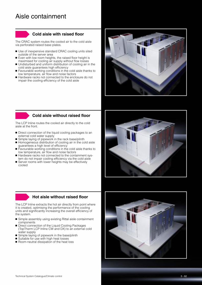
3 - 62
Aisle containment
Technical System Catalogue/Climate control
Cold aisle with raised floor
The CRAC system routes the cooled air to the cold aisle via perforated raised base plates.
� Use of inexpensive standard CRAC cooling units sited outside of the server area
� Even with low room heights, the raised floor height is maximised for cooling air supply without flow losses
� Undisturbed and uniform distribution of cooling air in the cold aisle guarantees high efficiency
� Favourable working conditions in the cold aisle thanks to low temperature, air flow and noise factors
� Hardware racks not connected to the enclosure do not impair the cooling efficiency of the cold aisle
Cold aisle without raised floor
The LCP Inline routes the cooled air directly to the cold aisle at the front.
� Direct connection of the liquid cooling packages to an external cold water supply
� Simple laying of pipework in the rack base/plinth� Homogeneous distribution of cooling air in the cold aisle
guarantees a high level of efficiency� Favourable working conditions in the cold aisle thanks to
low temperature, air flow and noise factors� Hardware racks not connected to the containment sys-
tem do not impair cooling efficiency via the cold aisle� Server rooms with lower heights may be effectively
cooled
Hot aisle without raised floor
The LCP Inline extracts the hot air directly from point where it is created, optimising the performance of the cooling units and significantly increasing the overall efficiency of the system.
� Simple assembly using existing Rittal aisle containment components
� Direct connection of the Liquid Cooling Packages (TopTherm LCP Inline CW and DX) to an external cold water supply
� Simple laying of pipework in the base/plinth� Suitable for use with high heat losses� Room-neutral dissipation of the heat loss
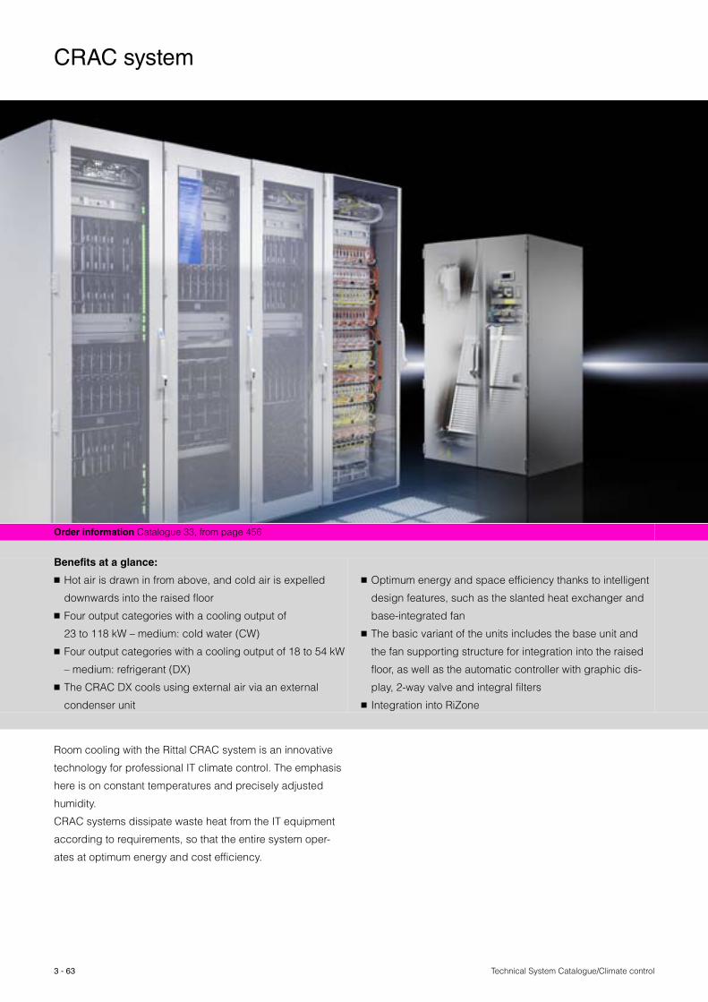
Technical System Catalogue/Climate control3 - 63
Order information Catalogue 33, from page 456
Benefits at a glance:
� Hot air is drawn in from above, and cold air is expelled
downwards into the raised floor
� Four output categories with a cooling output of
23 to 118 kW – medium: cold water (CW)
� Four output categories with a cooling output of 18 to 54 kW
– medium: refrigerant (DX)
� The CRAC DX cools using external air via an external
condenser unit
� Optimum energy and space efficiency thanks to intelligent
design features, such as the slanted heat exchanger and
base-integrated fan
� The basic variant of the units includes the base unit and
the fan supporting structure for integration into the raised
floor, as well as the automatic controller with graphic dis-
play, 2-way valve and integral filters
� Integration into RiZone
Room cooling with the Rittal CRAC system is an innovative
technology for professional IT climate control. The emphasis
here is on constant temperatures and precisely adjusted
humidity.
CRAC systems dissipate waste heat from the IT equipment
according to requirements, so that the entire system oper-
ates at optimum energy and cost efficiency.
CRAC system

3 - 64Technical System Catalogue/Climate control
Rittal CRAC DX system
� The refrigerant-cooled CRAC DX system operates in conjunction with an external condenser unit that utilises external air for cooling. This combination is used prima-rily in small locations with a low cooling output.
� The CRAC DX system operates on the principle of direct evaporation, and is fitted as standard with the innovative Energy Save Control (ESC): At reduced external tem-peratures, the power consumption of the compressors is reduced while at the same time, their cooling output rises, so that redundant compressors may be switched off.
Rittal CRAC CW system
� The water-cooled CRAC CW system may be used in conjunction with a Rittal IT chiller, so that the operating costs of the system may be reduced still further with optimum use of the external temperatures.
� The CRAC CW system is designed for IT rooms with a high thermal load, and may be combined with various mechanical cooling systems such as chillers or free coolers. Thanks to the underfloor fan arrangement, the enclosure is able to accommodate a filter and heat exchanger with increased surface areas.
Energy saving through redundancy
� More space for larger heat exchangers and filters� High cooling output with minimal space requirement and
small footprint� Low power consumption in year-round operation� Very high energy-saving figures� Low maintenance costs
Energy saving through redundancy operation:3.3 kW at 44000 m3/h air volume
2 fan units at full load,1 fan unit standby:2 x 3 kW = 6 kW
3 fan units at partial load:3 x 0.9 kW = 2.7 kW
CRAC system

Technical System Catalogue/Climate control
CRAC CW system with cold aisle containment
3 - 65
Order information Catalogue 33, page 460
By using Rittal cold aisle containment in conjunction with
the Rittal CRAC system, you can optimise climate control
of the room in terms of energy efficiency and cooling
output.
� High energy efficiency
� Increased cooling output per server rack
� Easily retro-fitted to existing systems
� Protection of your existing infrastructure
� The Mean Time Between Failures (MTBF) of existing
systems can be significantly extended
Instead of flooding the room with cold air, this Rittal concept
routes the cold air directly to the equipment via the cold
aisle. Cold air is directed across the whole height of the
enclosure, ensuring that there are no hot-spots, and the hot
air is exhausted out of the system. Due to the cold aisle
being contained, there is no chance of the hot exhaust air
mixing with the cold inlet air, leading to an increase in sys-
tem efficiency.
The outstanding energy efficiency of the Rittal cold aisle
concept has a simple explanation:
1. The intake air (cold) and waste air (hot) cannot mix.
2. The system may be operated at a significantly higher
temperature level.
3. Thanks to the increased temperature difference between
the intake air and waste air, the cooling performance and
efficiency of the climate control units are optimised.

Technical System Catalogue/Climate control
Sample calculation
3 - 66
Step 1: Raise the water inlet temperature
The temperature in the cold aisle is precisely definable and identical throughout, thanks to optimised temperature distribution.
� Increasing the air intake temperature also increases the waste air temperature.
� Increasing the air intake temperature improves the performance of free cooling.
Possible energy saving in the production of chilled water: up to 26%.
Qtotal (Qsens.) 80 kW (80 kW) – 79.9 kW (79.9 kW)Tair; hot (rel. humidity) 26 °C (45%) – 31 °C (32%)Tair; cold (rel. humidity) 15 °C (89%) – 19.8 °C (62.2%)Twater; inlet 10 °C – 15 °CTwater; return 15 °C – 20 °CPelectr. for cold water 190 MWh/a – 139 MWh/a
–26%
Step 2: Reduce the volumetric air flow
For a constant air volume flow rate, the cooling output improves with airside temperature difference.
� By reducing the volumetric air flow, the return waste air temperature is increased,
Possible energy saving in the operation of the fans: up to 60%.
Qtotal (Qsens.) 79.9 kW (79.9 kW) – 88.4 kW (88.4 kW)Tair; hot (rel. humidity) 31 °C (32%) – 36 °C (25%)Tair; cold (rel. humidity) 19.8 °C (62.2%) – 19.7 °C (64.6%)Vair (ext. press.) 22000 m3/h (80 Pa) – 17000 m3/h (20 Pa)Pelectr. for CRAC fan 3.6 kW – 1.5 kW
–60%
Step 3: Reduce the throughput
The speed of the pump may be reduced because a smaller amount of cooling water is required to provide the same cooling output if the return water temperature is increased.
Possible energy saving in the operation of the pump: up to 14%.
Potential saving in the production of chilled water: up to 17%.
Qtotal (Qsens.) 88.4 kW (88.4 kW) – 80 kW (80 kW)Tair; hot (rel. humidity) 36 °C (25%) – 36 °C (25%)Tair; cold (rel. humidity) 19.7 °C (64.6%) – 21.3 °C (54.2%)Twater; inlet 15 °C – 15 °CTwater; return 20.6 °C – 23.5 °CVwater (Pelectr. ) 13.6 m3/h (3 kW) – 8.1 m3/h (2.3 kW)Pelectr. for cold water 143 MWh/a – 125 MWh/a
–17%
Summary
Energy saving:
� Fans: 19 MWh/a� Pumps: 6 MWh/a� Cold water production: 65 MWh/a� Overall: 90 MWh/a
Cost saving with Rittal aisle containment: up to 36%.
Qtotal (Qsens.) 80 kW (80 kW) – 80 kW (80 kW)Tair; hot (rel. humidity) 26 °C (45%) – 36 °C (25%)Tair; cold (rel. humidity) 15 °C (89%) – 21.3 °C (54.2%)Vair (ext. press.) 22000 m³/h (80 Pa) – 17000 m³/h (20 Pa)Twater; inlet 10 °C – 15 °CTwater; return 15 °C – 23.5 °CVwater (Pelectr. ) 13.8 m3/h (3 kW) – 8.09 m3/h (2.3 kW)Pelectr. for CRAC fan 3.6 kW – 1.5 kWPelectr. for cold water 190 MWh/a – 125 MWh/aPelectr. Total 248 MWh/a – 158 MWh/a –36%

Technical System Catalogue/Climate control3 - 67
Order information Catalogue 33, from page 461
Liquid Cooling Package
Data centres support corporate process with ever-growing
output. The packing density in computer systems is increas-
ing, and processor capacity is growing.
This leads to a continuous growth in heat development.
You can keep temperatures at a constant level with the
highly efficient Rittal Liquid Cooling Packages. With opti-
mised operating costs, our LCPs precisely and effortlessly
dissipate heat losses of up to 60 kW per enclosure.
Rittal bayed suite climate control is extremely powerful and
the ideal solution for extremely high cooling demands, par-
ticularly when the cooling of server racks cannot be achieved
via the room climate control. Alternatively, bayed suite cool-
ing can be used to support the existing climate control sys-
tem in the room or for transforming existing structures into
server rooms. A raised floor is not necessary for the opera-
tion of suite cooling.
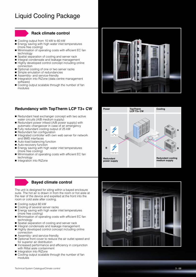
3 - 68Technical System Catalogue/Climate control
Rack climate control
� Cooling output from 10 kW to 60 kW� Energy saving with high water inlet temperatures
(more free cooling)� Minimisation of operating costs with efficient EC fan
technology� Spatial separation of cooling and server rack� Integral condensate and leakage management� Highly developed control concept including online
connection� Optional cooling of one or two server racks� Simple emulation of redundancies� Assembly- and service-friendly� Integration into RiZone (data centre management
software)� Cooling output scalable through the number of fan
modules
Redundancy with TopTherm LCP T3+ CW
� Redundant heat exchanger concept with two active water circuits (A/B medium supply)
� Redundant power infeed (A/B power supply) with automatic changeover in case of an emergency
� Fully redundant cooling output of 25 kW� Redundant fan configuration� Integrated controller with own web server for network
and BMS interfaces� Auto-load balancing function� Auto-recovery function� Energy saving with high water inlet temperatures
(more free cooling)� Minimisation of operating costs with efficient EC fan
technology� Integration into RiZone
Power TopTherm LCP T3+ CW
Cooling
Redundant power supply
Redundant cooling medium supply
A
B B
A
Bayed climate control
The unit is designed for siting within a bayed enclosure suite. The hot air is drawn in from the room or hot aisle at the rear of the device and expelled at the front into the room or cold aisle after cooling.
� Cooling output 60 kW� Cooling of several server racks� Energy saving with high water inlet temperatures
(more free cooling)� Minimisation of operating costs with efficient EC fan
technology� Spatial separation of cooling and server rack� Integral condensate and leakage management� Highly developed control concept including online
connection� Assembly- and service-friendly� Optional front cover to reduce the air outlet speed and
for superior air distribution� Increased performance and efficiency in conjunction
with Rittal aisle containment� Integration into RiZone� Cooling output scalable through the number of fan
modules
Liquid Cooling Package
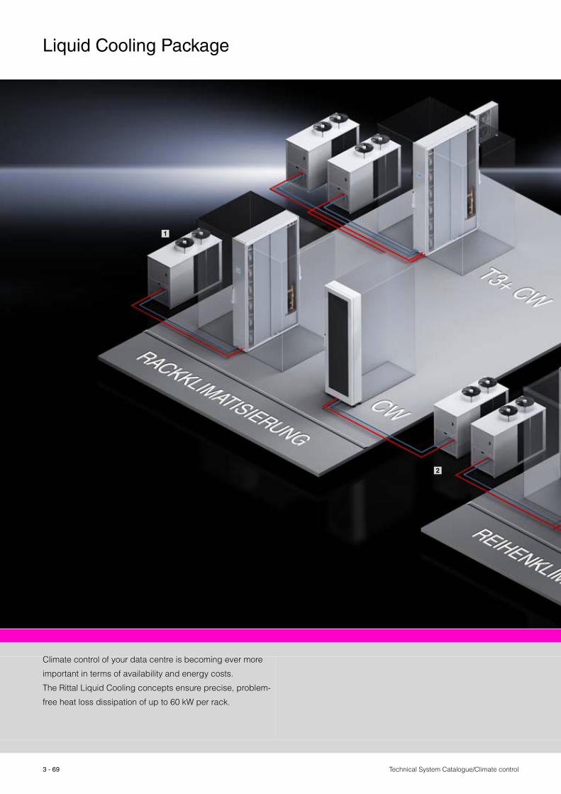
Technical System Catalogue/Climate control
Liquid Cooling Package
3 - 69
Climate control of your data centre is becoming ever more
important in terms of availability and energy costs.
The Rittal Liquid Cooling concepts ensure precise, problem-
free heat loss dissipation of up to 60 kW per rack.
1
2

Technical System Catalogue/Climate control
Liquid Cooling Package
3 - 70
Rack climate control CW via chillerBayed climate control CW via chiller
CW = Chilled Water
1
2

Technical System Catalogue/Climate control
Liquid Cooling Package
3 - 71
Rack climate controlThe LCP for rack climate control is designed for siting within a bayed enclosure suite. The cold air is expelled sideways on the front of the servers, and warm air is drawn back in at the rear. The LCP for rack climate con-trol is ideal for maximum cooling performance and maxi-mum fail-safeness, thanks to redundancy of all key com-ponents.
A large-scale high-capacity air/water heat exchanger, designed as the rear door of the server enclosure, ensures that heated waste air from the servers is cooled down to server intake air level. This is achieved extremely energy-efficiently, because no electrical power is required for fans. High inlet temperatures above the dew point improve energy efficiency still further.
Technology CW = Chilled WaterT3+ = for Tier 3
CW T3+ CW CW
Output kW 10, 20, 30, 40, 50, 60 25 20
Cooling medium Water Water WaterAuto-load balancing – � – Auto-recovery – � –

Technical System Catalogue/Climate control
Liquid Cooling Package
3 - 72
Bayed climate controlThe LCP for bayed climate control is designed for siting within a bayed enclosure suite. The hot air is drawn in from the room or hot aisle at the rear of the device and expelled at the front into the cold aisle after cooling. The LCP for inline bayed climate control achieves maximum performance and efficiency in conjunction with Rittal cold aisle containment.
Technology CW = Chilled Water
CWSet forward variant
CWFlush variant
Output kW 10, 20, 30, 40, 50, 60 30
Cooling medium Water WaterAuto-load balancing – – Auto-recovery – –
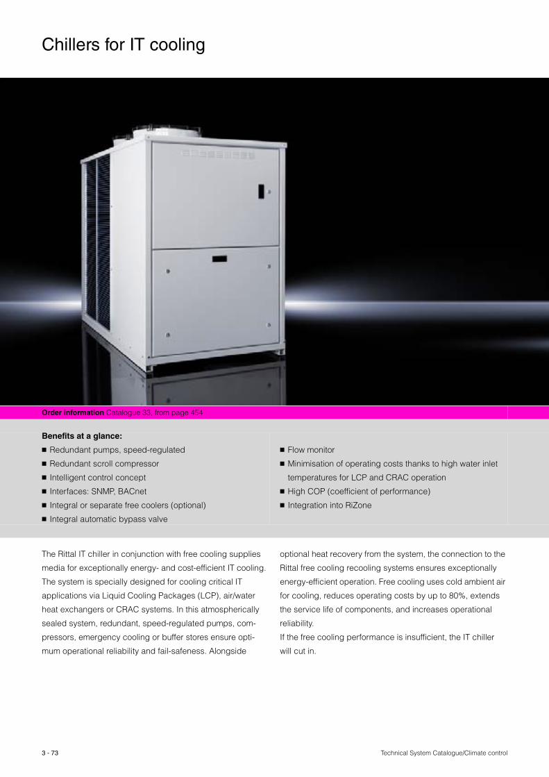
Technical System Catalogue/Climate control3 - 73
Order information Catalogue 33, from page 454
Benefits at a glance:
� Redundant pumps, speed-regulated
� Redundant scroll compressor
� Intelligent control concept
� Interfaces: SNMP, BACnet
� Integral or separate free coolers (optional)
� Integral automatic bypass valve
� Flow monitor
� Minimisation of operating costs thanks to high water inlet
temperatures for LCP and CRAC operation
� High COP (coefficient of performance)
� Integration into RiZone
The Rittal IT chiller in conjunction with free cooling supplies
media for exceptionally energy- and cost-efficient IT cooling.
The system is specially designed for cooling critical IT
applications via Liquid Cooling Packages (LCP), air/water
heat exchangers or CRAC systems. In this atmospherically
sealed system, redundant, speed-regulated pumps, com-
pressors, emergency cooling or buffer stores ensure opti-
mum operational reliability and fail-safeness. Alongside
optional heat recovery from the system, the connection to the
Rittal free cooling recooling systems ensures exceptionally
energy-efficient operation. Free cooling uses cold ambient air
for cooling, reduces operating costs by up to 80%, extends
the service life of components, and increases operational
reliability.
If the free cooling performance is insufficient, the IT chiller
will cut in.
Chillers for IT cooling
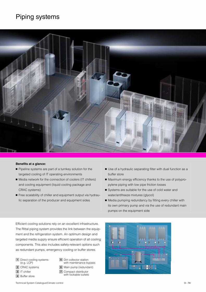
Technical System Catalogue/Climate control 3 - 74
Benefits at a glance:
� Pipeline systems are part of a turnkey solution for the
targeted cooling of IT operating environments
� Media network for the connection of coolers (IT chillers)
and cooling equipment (liquid cooling package and
CRAC systems)
� Free scalability of chiller and equipment output via hydrau-
lic separation of the producer and equipment sides
� Use of a hydraulic separating filter with dual function as a
buffer store
� Maximum energy efficiency thanks to the use of polypro-
pylene piping with low pipe friction losses
� Systems are suitable for the use of cold water and
water/antifreeze mixtures (glycol)
� Media pumping redundancy by fitting every chiller with
its own primary pump and via the use of redundant main
pumps on the equipment side
Efficient cooling solutions rely on an excellent infrastructure.
The Rittal piping system provides the link between the equip-
ment and the refrigeration system. An optimum design and
targeted media supply ensure efficient operation of all cooling
components. This also includes safety-relevant options such
as redundant pumps, emergency cooling or buffer stores.
1 2
4
3
7
5 6
Direct cooling systems (e.g. LCP)
CRAC systems
IT chiller
Buffer store
Dirt collector station with maintenance bypass
Main pump (redundant)
Compact distributor with lockable outlets
1
2
3
4
5
6
7
Piping systems

Technical System Catalogue/Climate control3 - 75
Speed-controlled pump
Speed-controlled pumps are used to convey the coolant. The pumped volume may be varied by using state-of-the-art EC motors.
Your practical benefit: Lower energy consumption thanks to “cold water on demand”. Only the volume of water that is actually needed for cooling is moved through the system.
Standard hydraulic layout
The standard hydraulic layout includes the use of a hydrau-lic separating filter. Different volumes of water on the pro-ducer side and equipment side for process cooling do not adversely affect the function of the cooling systems.
Your practical benefit: Less energy consumption via the use of free cooling heat exchangers including redundancy. Chiller pumps may be activated and deactivated as required.
Use of compact distributors
Use of compact distributors to distribute the cooling medium among different pieces of equipment.
Your practical benefit: Redundancies in the supply lines to the equipment may be designed as required. For example, a layout can be designed to facilitate the automatic shut-off of sub-sections in the event of pipe leaks.
Innovative pipework
The innovative polypropylene piping is distinguished by minimal pipe friction resistance.
Your practical benefit: Less energy consumption for conveying the cooling medium, thanks to lower flow resistance. The material is corrosion-resistant and may be machined without residues.
Piping systems

Technical System Catalogue/Climate control 3 - 76
Order information Catalogue 33, from page 203 – 209
CS Outdoor climate control
Benefits at a glance:
� The IP 55 protection category of the enclosures is retained
� Hermetically separate air circuits – Contaminated ambient
air is unable to ingress the enclosure
� Backup-compatible 48 V DC air/air heat exchangers
� Integral heater in many units
Please note:
� CS Outdoor cooling units and CS Outdoor heat exchang-
ers are manufactured to order
� CS Outdoor cooling units and CS Outdoor heat exchang-
ers are supplied as fully integrated units on the CS Outdoor
enclosure. Mounting on other Rittal enclosures is only
possible by arrangement.
The Rittal Outdoor range offers everything you need to pro-
tect your electronic equipment, from weather-tested enclo-
sure solutions, to a variety of climate control components,
through to complete security management systems.
Cooling units, heat exchangers, fans and heaters especially
designed for outdoor use ensure constant interior tempera-
tures. A protection category of IP 55 is retained for the sys-
tem as a whole when using Outdoor heat exchangers and
cooling units. Rittal has conducted in-depth studies and
accumulated wide-ranging expertise in the calculation and
design of climate control units for outdoor siting.
Rittal offers a free calculation service for determining the
required output of climate control units in outdoor applica-
tions. The broad range of products and materials offers maxi-
mum protection for your equipment, tested to international
provisions and standards such as IEC, ETSI, Bellcore, NEMA
and UL. With this wide variety of materials, Rittal is able
to achieve the level of corrosion protection required for a
specific location.
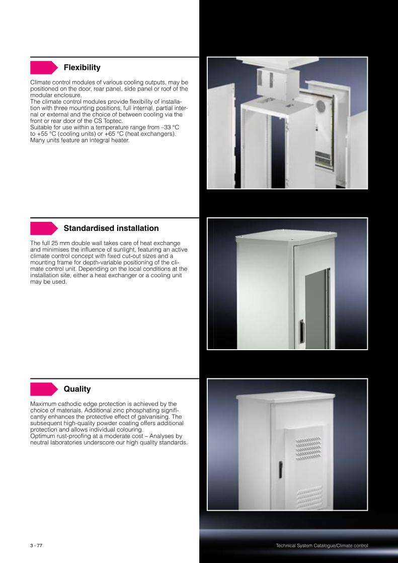
Technical System Catalogue/Climate control3 - 77
Flexibility
Climate control modules of various cooling outputs, may be positioned on the door, rear panel, side panel or roof of the modular enclosure. The climate control modules provide flexibility of installa-tion with three mounting positions, full internal, partial inter-nal or external and the choice of between cooling via the front or rear door of the CS Toptec. Suitable for use within a temperature range from –33 °C to +55 °C (cooling units) or +65 °C (heat exchangers). Many units feature an integral heater.
Standardised installation
The full 25 mm double wall takes care of heat exchange and minimises the influence of sunlight, featuring an active climate control concept with fixed cut-out sizes and a mounting frame for depth-variable positioning of the cli-mate control unit. Depending on the local conditions at the installation site, either a heat exchanger or a cooling unit may be used.
Quality
Maximum cathodic edge protection is achieved by the choice of materials. Additional zinc phosphating signifi-cantly enhances the protective effect of galvanising. The subsequent high-quality powder coating offers additional protection and allows individual colouring. Optimum rust-proofing at a moderate cost – Analyses by neutral laboratories underscore our high quality standards.

Technical System Catalogue/Climate control
CS Outdoor climate control
3 - 78
Order information Catalogue 33, page 468
Air/air heat exchangers and cooling units for CS Toptec
Benefits at a glance:
� Wtih sealing frame for universal attachment in 3 positions:
internal, partial internal and external
� Air/air heat exchangers, specific thermal output 85 W/K
and 105 W/K
� Cooling units, useful cooling output 1000 W – 1750 W
At many locations worldwide, a temperature range of more
than 50 K (e.g. minimum temperature –15 °C and maximum
temperature +40 °C) has been measured in outdoor installa-
tions. When using equipment suitable for outdoor use, which
operates correctly at interior temperatures of up to +55 °C,
an air/air heat exchanger may be used for climate control
purposes. The air/air heat exchanger has hermetically sepa-
rated air circuits and uses the ambient air to cool the raised
interior temperature at the heat exchanger module. With
a correctly designed heat exchanger, this climate control
concept is capable of limiting temperatures inside the
enclosure which are 10 K higher than the ambient tempera-
ture. The application range of the installed components is
crucial when selecting the right climate control unit. If equip-
ment intended for indoor applications is used outdoors at
an ambient temperature of up to approximately +35 °C,
a compressor cooling unit must be used. Only cooling units
can achieve temperatures in the enclosure interior which are
lower than the ambient temperature.

Technical System Catalogue/Climate control
CS Outdoor climate control
3 - 79
Order information Catalogue 33, page 469
Air/air heat exchangers and cooling units for CS modular enclosures
Benefits at a glance:
� Air/air heat exchangers for roof mounting,
spec. thermal output 30 W/K
� Cooling units for roof mounting,
useful cooling output 720 W – 1020 W
� Cooling units for wall mounting,
useful cooling output 750 W – 1050 W
� Cooling units for partial internal mounting,
useful cooling output 1250 W – 1600 W
Protection of the installed equipment is of central importance
in many locations, particularly outdoor enclosures which
may be sited in public spaces, need to be cleverly designed
to protect against unauthorised access. Depending on the
enclosure platform, the specified design principles are in-
corporated into the standard enclosure.
Some basic design principles:
� No externally visible or accessible screws. If screws are
unavoidable, special screw heads are used.
� Minimal gap between doors and side panels, no leverage
points.
� Modified closure and lock concepts, e.g. 3-point lock or
better.
The basic design of the enclosures also plays a major role
with regard to additional heating from sunlight: While single-
walled enclosures can heat up to extreme levels, the chim-
ney effect resulting from a twin-walled design reduces the
influence of sunlight.
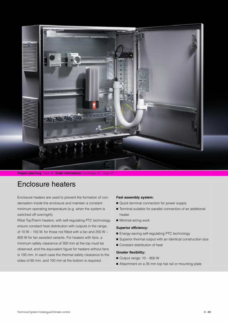
Technical System Catalogue/Climate control 3 - 80
Project planning Page 82 Order information Catalogue 33, page 471
Enclosure heaters
Enclosure heaters are used to prevent the formation of con-
densation inside the enclosure and maintain a constant
minimum operating temperature (e.g. when the system is
switched off overnight).
Rittal TopTherm heaters, with self-regulating PTC technology,
ensure constant heat distribution with outputs in the range;
of 10 W – 150 W, for those not fitted with a fan and 250 W –
800 W for fan assisted variants. For heaters with fans, a
minimum safety clearance of 300 mm at the top must be
observed, and the equivalent figure for heaters without fans
is 100 mm. In each case the thermal safety clearance to the
sides of 60 mm, and 100 mm at the bottom is required.
Fast assembly system:
� Quick terminal connection for power supply
� Terminal suitable for parallel connection of an additional
heater
� Minimal wiring work
Superior efficiency:
� Energy-saving self-regulating PTC technology
� Superior thermal output with an identical construction size
� Constant distribution of heat
Greater flexibility:
� Output range: 10 – 800 W
� Attachment on a 35 mm top hat rail or mounting plate

Technical System Catalogue/Climate control
Enclosure heaters
3 - 81
Fast assembly
� Snap-fastening onto 35 mm support rails EN 50 022� Direct screw-fastening onto the mounting plate� Quick terminal connection for power supply
(spring terminal)� No need for any other terminals� No wiring required
Energy-efficient design
� PTC technology for constant heat distribution � Computational Fluid Dynamics (CFD)-assisted design
for superior heating performance with an identical con-struction size
Output range
� Without fan 10 W, 20 W, 30 W, 50 W, 75 W, 100 W, 150 W� With fan 250 W, 400 W, 800 W� Voltage ranges− 110 V – 240 V, 50/60 Hz− 115 V, 50/60 Hz− 230 V, 50/60 Hz
Self-regulating PTC technology
Energy-efficient PTC technology and an optimised design using computational fluid dynamics (CFD) permit improved heating outputs from units of the same size compared to the previous product versions.
300
250
200
150
100
30
–30 –20 –10 0 10 20 30
0
Ambient temperature [°C]
Hea
ting
outp
ut [W
]
Heating performance diagram for a PTC heater

Technical System Catalogue/Climate control
Enclosure heaters
3 - 82
Project planning
Enclosure heaters
The required thermal output is calculated from:
Heating performance diagram
QH = Thermal output (W)A = Enclosure surface area to IEC 890 (m2)ΔT = Temperature difference (K)
Based on:Interior siting, static air, heat transfer coefficient k = 5.5 W/m2 K
For exterior siting (moving air): Double the determined thermal output
QH = A � ΔT � k.
A
ΔT
1
1.5
2
3
4568
10
15 30 50 150 300 50010 20 40 60 80 100 200
20
30
2 5 7.5 10
15
QH.
.
Even temperature distribution
Via a CFD analysis, even temperature distri-bution in the (empty) enclosure is observed when using a 400 W enclosure heater fol-lowing a heating period of approx. 30 minutes.
According to the CFD analysis, positioning of the enclosure heater in the base area of the enclosure is essential for even tempera-ture control of the enclosure, since those areas located beneath the heater are only minimally warmed.
25.0000
Temperature °C
22.5000
20.0000
17.5000
15.0000
12.5000
10.0000
7.50000
5.00000Start After 5 minutes
After 15 minutes After 30 minutes
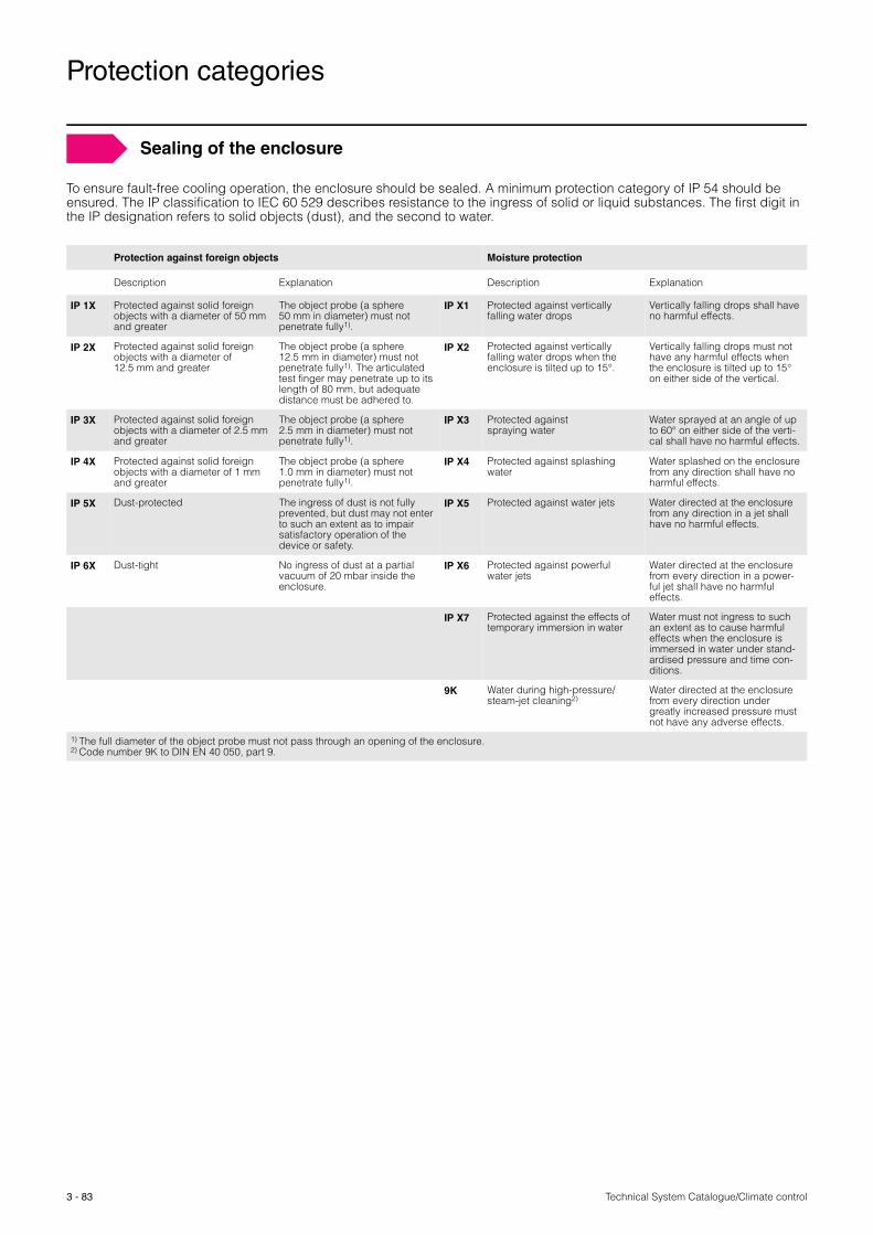
3 - 83 Technical System Catalogue/Climate control
Protection categories
To ensure fault-free cooling operation, the enclosure should be sealed. A minimum protection category of IP 54 should be ensured. The IP classification to IEC 60 529 describes resistance to the ingress of solid or liquid substances. The first digit in the IP designation refers to solid objects (dust), and the second to water.
Protection against foreign objects Moisture protection
Description Explanation Description Explanation
IP 1X Protected against solid foreign objects with a diameter of 50 mm and greater
The object probe (a sphere 50 mm in diameter) must not penetrate fully1).
IP X1 Protected against vertically falling water drops
Vertically falling drops shall have no harmful effects.
IP 2X Protected against solid foreign objects with a diameter of 12.5 mm and greater
The object probe (a sphere 12.5 mm in diameter) must not penetrate fully1). The articulated test finger may penetrate up to its length of 80 mm, but adequate distance must be adhered to.
IP X2 Protected against vertically falling water drops when the enclosure is tilted up to 15°.
Vertically falling drops must not have any harmful effects when the enclosure is tilted up to 15° on either side of the vertical.
IP 3X Protected against solid foreign objects with a diameter of 2.5 mm and greater
The object probe (a sphere 2.5 mm in diameter) must not penetrate fully1).
IP X3 Protected againstspraying water
Water sprayed at an angle of up to 60° on either side of the verti-cal shall have no harmful effects.
IP 4X Protected against solid foreign objects with a diameter of 1 mm and greater
The object probe (a sphere 1.0 mm in diameter) must not penetrate fully1).
IP X4 Protected against splashing water
Water splashed on the enclosure from any direction shall have no harmful effects.
IP 5X Dust-protected The ingress of dust is not fully prevented, but dust may not enter to such an extent as to impair satisfactory operation of the device or safety.
IP X5 Protected against water jets Water directed at the enclosure from any direction in a jet shall have no harmful effects.
IP 6X Dust-tight No ingress of dust at a partial vacuum of 20 mbar inside the enclosure.
IP X6 Protected against powerful water jets
Water directed at the enclosure from every direction in a power-ful jet shall have no harmful effects.
IP X7 Protected against the effects of temporary immersion in water
Water must not ingress to such an extent as to cause harmful effects when the enclosure is immersed in water under stand-ardised pressure and time con-ditions.
9K Water during high-pressure/steam-jet cleaning2)
Water directed at the enclosure from every direction under greatly increased pressure must not have any adverse effects.
1) The full diameter of the object probe must not pass through an opening of the enclosure.2) Code number 9K to DIN EN 40 050, part 9.
Sealing of the enclosure

Technical System Catalogue/Climate control 3 - 84
Order information Catalogue 33, from page 473
Climate control accessories
Benefits at a glance:
� Complete system solutions
� Perfectly coordinated components
Finding the perfect climate control solution is now even
easier with the right system accessories that adapt the
climate control components perfectly to your requirements.
From parameter setting to targeted air routing and precise
control of the equipment, Rittal has the right solution for all
of your needs.
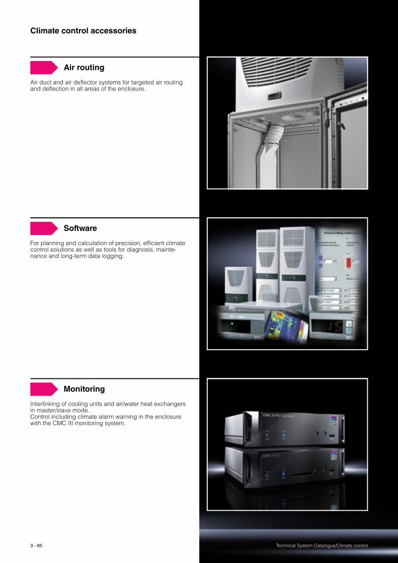
Technical System Catalogue/Climate control3 - 85
Air routing
Air duct and air deflector systems for targeted air routing and deflection in all areas of the enclosure.
Software
For planning and calculation of precision, efficient climate control solutions as well as tools for diagnosis, mainte-nance and long-term data logging.
Monitoring
Interlinking of cooling units and air/water heat exchangers in master/slave mode. Control including climate alarm warning in the enclosure with the CMC III monitoring system.
Climate control accessories

Technical System Catalogue/Climate control
Air routing
3 - 86
For wall-mounted unitsUsed in conjunction with climate control side panels and TopTherm wall-mounted cooling units for targeted air routing of the cold air in a downward direction. Particularly well-suited for densely-packed electrical components in the lower section of the enclosure.
See Cat. 33, page 475.
Air diverter systems
For TopTherm roof-mounted cooling systems It is possible to route the cold air directly to specific areas of the enclosure using the air duct system. The risk of “short circuits” in the air circulation due to self-ventilated installed devices is therefore eliminated.
Note:� Never direct the cold air flow straight at active compo-
nents.� Route the air duct system directly downwards with no
bends.� Cold air must be able to escape unobstructed at the end
of the duct.� Additional deflections will reduce the useful cooling output.� When using the ducting system, the performance of the
cooling unit may be reduced, depending on the respec-tive application.
The air duct system should not be extended. CAUTION Risk of icing!
1
Accessories:Air duct system for roof-mounted units, see Cat. 33, page 473/474.
1
Air duct system
For TopTherm roof-mounted cooling systemsFor sealing cold air outlets that are not required in cooling units and air/water heat exchangers.
Note:At least two outlet openings must always remain open!
Please note that if two or three openings are closed, the cool-ing output may be reduced by 20% and 30% respectively!
See Cat. 33, page 474.
For unitsMax. no.
of stoppers per unit
Packs of Model No. SK
SK 3359.…/SK 3382.… 1 2 3286.780
SK 3209.…/SK 3210.…/SK 3273.…/SK 3383.…/SK 3384.…/SK 3385.…
2 2 3286.880
SK 3386.…/SK 3387.… 1 2 3286.980
max. 2x
max. 1x
Stoppers
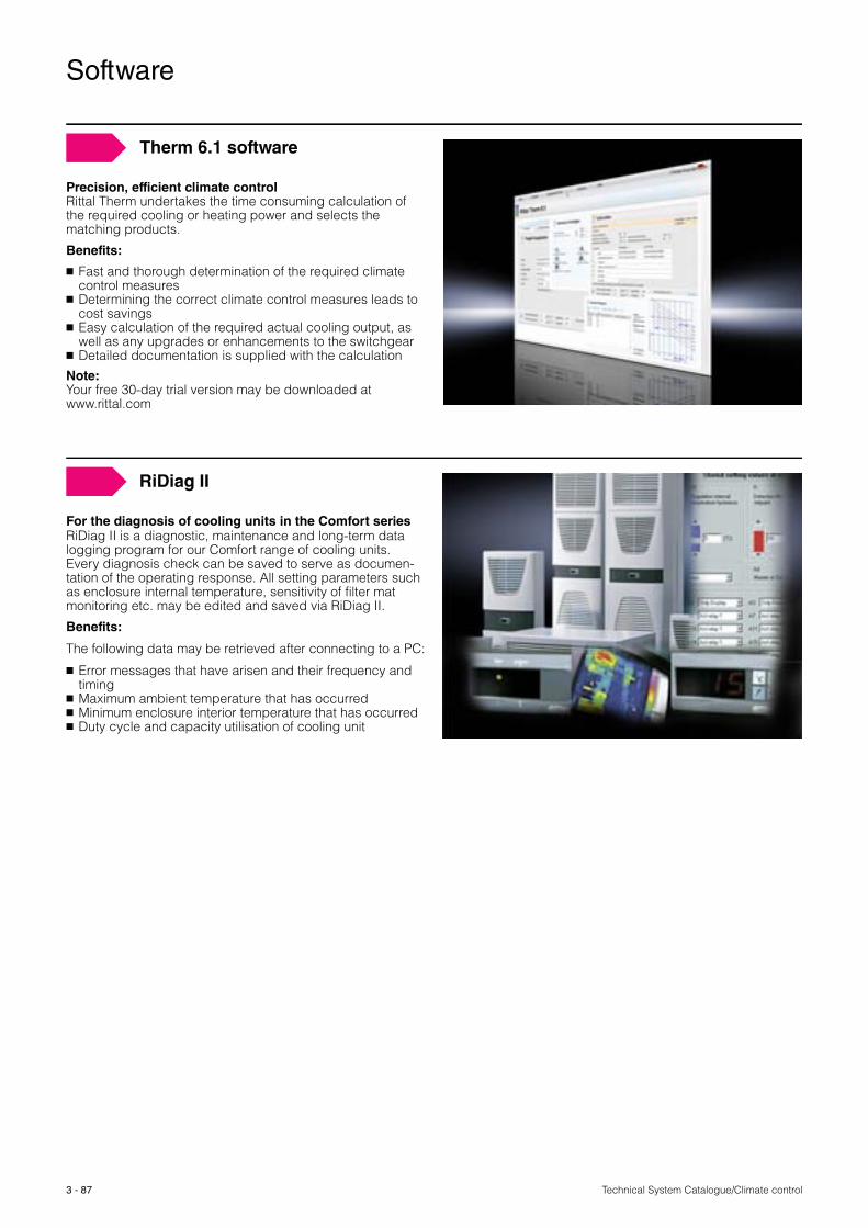
Technical System Catalogue/Climate control
Software
3 - 87
Precision, efficient climate controlRittal Therm undertakes the time consuming calculation of the required cooling or heating power and selects the matching products.
Benefits:
� Fast and thorough determination of the required climate control measures
� Determining the correct climate control measures leads to cost savings
� Easy calculation of the required actual cooling output, as well as any upgrades or enhancements to the switchgear
� Detailed documentation is supplied with the calculation
Note: Your free 30-day trial version may be downloaded at www.rittal.com
Therm 6.1 software
For the diagnosis of cooling units in the Comfort series RiDiag II is a diagnostic, maintenance and long-term data logging program for our Comfort range of cooling units. Every diagnosis check can be saved to serve as documen-tation of the operating response. All setting parameters such as enclosure internal temperature, sensitivity of filter mat monitoring etc. may be edited and saved via RiDiag II.
Benefits:
The following data may be retrieved after connecting to a PC:
� Error messages that have arisen and their frequency and timing
� Maximum ambient temperature that has occurred� Minimum enclosure interior temperature that has occurred� Duty cycle and capacity utilisation of cooling unit
RiDiag II
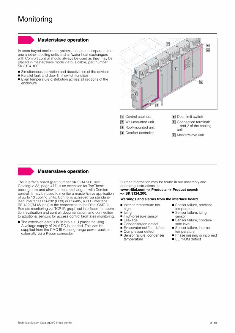
Technical System Catalogue/Climate control
Monitoring
3 - 88
In open bayed enclosure systems that are not separate from one another, cooling units and air/water heat exchangers with Comfort control should always be used as they may be placed in master/slave mode via bus cable, part number SK 3124.100:
� Simultaneous activation and deactivation of the devices� Parallel fault and door limit switch function � Even temperature distribution across all sections of the
enclosure
1
2
3
7
4
5
5
6
Master/slave operation
Control cabinetsWall-mounted unitRoof-mounted unitComfort controller
Door limit switchConnection terminals 1 and 2 of the cooling unitMaster/slave unit
1
2
3
4
5
6
7
The interface board (part number SK 3214.200, see Catalogue 33, page 477) is an extension for TopTherm cooling units and air/water heat exchangers with Comfort control. It may be used to monitor a master/slave application of up to 10 cooling units. Control is achieved via standard-ised interfaces RS-232 (DB9) or RS-485, a PLC interface. RS-422 (RJ 45 jack) is the connection to the Rittal CMC III. Remote monitoring via TCP-IP, graphical interfaces for opera-tion, evaluation and control, documentation, and connection to additional sensors for access control facilitates monitoring.
� The extension card is built into a 1 U plastic housing. A voltage supply of 24 V DC is needed. This can be supplied from the CMC III via long-range power pack or externally via a Kycon connector.
Master/slave operation
Further information may be found in our assembly and operating instructions, at www.rittal.com –> Products –> Product search–> SK 3124.200.
Warnings and alarms from the interface board
� Interior temperaure too high
� Icing� High-pressure sensor� Leakage� Condenser/fan defect� Evaporator coil/fan defect� Compressor defect� Sensor failure, condenser
temperature
� Sensor failure, ambient temperature
� Sensor failure, icing sensor
� Sensor failure, conden-sate level
� Sensor failure, internal temperature
� Phase missing or incorrect � EEPROM defect
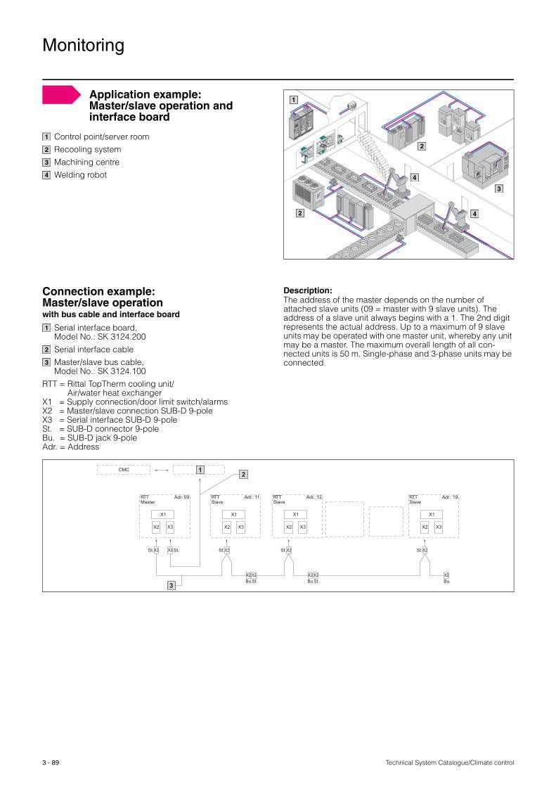
Technical System Catalogue/Climate control
Monitoring
3 - 89
Control point/server roomRecooling systemMachining centreWelding robot
1
2
2
3
4
4
1
2
3
4
Application example: Master/slave operation and interface board
Connection example: Master/slave operationwith bus cable and interface board
Serial interface board,Model No.: SK 3124.200Serial interface cableMaster/slave bus cable, Model No.: SK 3124.100
RTT = Rittal TopTherm cooling unit/Air/water heat exchanger
X1 = Supply connection/door limit switch/alarmsX2 = Master/slave connection SUB-D 9-poleX3 = Serial interface SUB-D 9-poleSt. = SUB-D connector 9-poleBu. = SUB-D jack 9-poleAdr. = Address
Description:The address of the master depends on the number of attached slave units (09 = master with 9 slave units). The address of a slave unit always begins with a 1. The 2nd digit represents the actual address. Up to a maximum of 9 slave units may be operated with one master unit, whereby any unit may be a master. The maximum overall length of all con-nected units is 50 m. Single-phase and 3-phase units may be connected.
CMC
RTTMaster
Adr.: 09
X1
X2 X3
RTTSlave
Adr.: 11
X1
X2 X3
Adr.: 12
X1
X2 X3
Adr.: 19
X1
X2 X3
X2 X3 X2X2
X2 X2 X2 X2
X2
X2
St. St. St. St.
St.Bu. Bu.
St.
St.Bu.
1
RTTSlave
RTTSlave
2
3
1
2
3

Technical System Catalogue/Climate control
Monitoring
3 - 90
The CMC III monitoring system controls the climate inside the enclosure. The user specifies limits for his equipment inside the enclosure. These are fully automatically monitored by the CMC III system. If a limit is exceeded, the CMC III can report this to the service team via e-mail or SMS. Counteractive action may also be initiated automatically.
The system may also be connected to the customer network (via OPC/SNMP) to generate messages or values directly in the control room system (SCADA/BMS/NMS).
The basic unit contains the principal sensors and may be extended via the integral CAN bus.
The CMC III system is plug & play-ready, sensors are detected automatically, and the Web user interface is easy to use even with no programming knowledge.
The power supply is 24 V DC with a redundant design. The system may also be supplied via the integral Power over Ethernet (PoE).
The benefits of this system lie in its high level of reliability with automatic, direct initiation of counteractive action. Ever more complex applications are monitored by ever fewer person-nel. Staff may therefore rely on automated solutions to assist them in their duties and responsibilities.
Applications:
� Temperature monitoring� Humidity monitoring� Filter mat/fan monitoring via air flow sensor, analog (m/s)
with limits or speed control.� Cold aisle housing/raised floor monitoring via differential
pressure sensor, analog (Pa) with limits.� Air control/regulation� Heating control/regulation� CMC III switches climate control unit off automatically when
the enclosure door is open� CMC III reports malfunctions in the event of a defective
climate control unit� CMC III opens the enclosure doors automatically in the
event of a failure in the climate control system and uses the ambient air
� CMC III switches off the system in the event of overheating or shuts down a server in a controlled manner
Note: For further information see Catalogue 33, page 768 – 777.
Enclosure monitoring systemCMC III
CAN bus
08.2
012
� Enclosures� Power Distribution� Climate Control� IT Infrastructure� Software & Services
RITTAL GmbH & Co. KGPostfach 1662 · D-35726 HerbornPhone +49(0)2772 505-0 · Fax +49(0)2772 505-2319E-mail: [email protected] · www.rittal.com