technical specifications on grey water reuse ... - wsd.gov.hk · technical specifications on grey...
TRANSCRIPT
TECHNICAL SPECIFICATIONS
ON
GREY WATER REUSE AND
RAINWATER HARVESTING
1st Edition
Water Supplies Department
May 2015

Intentionally Left Blank
i
TABLE OF CONTENTS
1. Introduction .......................................................................................................................... 1 1.1 Objectives ..................................................................................................................... 1 1.2 Water Quality ................................................................................................................ 1
2. Design and Construction Requirements .............................................................................. 3
2.1 Grey Water Collection .................................................................................................. 3 2.2 Rainwater Collection .................................................................................................... 4 2.3 Collection Tank ............................................................................................................ 4 2.4 Grey Water Treatment .................................................................................................. 6 2.5 Rainwater Treatment .................................................................................................... 8
2.6 Combined Treatment for Grey Water and Rainwater ................................................. 10
2.7 Storage ........................................................................................................................ 10 2.8 Pumps ......................................................................................................................... 11
2.9 Mechanical Equipment ............................................................................................... 12 2.10 Electrical Equipment .................................................................................................. 12 2.11 Noise ........................................................................................................................... 13 2.12 Materials and Fittings ................................................................................................. 13
2.13 Power Supply .............................................................................................................. 13 2.14 Back-up Water Supply ................................................................................................ 13
2.15 Backflow Prevention .................................................................................................. 14 2.16 Overflow, Bypass, and Drainage ................................................................................ 15 2.17 Controls....................................................................................................................... 15
2.18 Sludge Holding Tank .................................................................................................. 16 2.19 Location and Access of Treatment Systems ............................................................... 16
2.20 Distribution ................................................................................................................. 16
3. Methodology in Assessing Quantity of Supply and Demand ............................................ 18
3.1 Introduction ................................................................................................................. 18 3.2 Rainwater Yield .......................................................................................................... 18
3.3 Grey Water Yield – Simplified Approach .................................................................. 18 3.4 Grey Water Yield – Detailed Approach ..................................................................... 19
3.5 Estimating Grey Water and Rainwater Demand ........................................................ 20
4. Installation ......................................................................................................................... 22 4.1 General ........................................................................................................................ 22 4.2 Tank Installation ......................................................................................................... 22 4.3 Cistern Installation ...................................................................................................... 22
5. Testing, Commissioning and Decommissioning ............................................................... 23 5.1 Commissioning Procedures ........................................................................................ 23
5.2 Cross Connection Test for Reclaimed Water Distribution System ............................ 24 5.3 Decommissioning Procedures .................................................................................... 25 5.4 Switch-off during Extended Service Suspension ....................................................... 26
6. Operation and Maintenance ............................................................................................... 27 6.1 System Management ................................................................................................... 27 6.2 Operations and Maintenance ...................................................................................... 27 6.3 Warranty and Guaranteed Service Life ...................................................................... 29
ii
6.4 Manuals ....................................................................................................................... 29
6.5 Submittals ................................................................................................................... 30
7. Requirements on Sampling, Monitoring, Flow Measurement and Record Keeping ......... 32 7.1 Sampling and Monitoring ........................................................................................... 32 7.2 Flow Measurement ..................................................................................................... 33
7.3 Record Keeping .......................................................................................................... 33
8. Marking and Labelling of Piping and Fittings ................................................................... 35 8.1 Identification of Pipelines and Services ..................................................................... 35 8.2 Labelling of Rainwater Collection Pipework ............................................................. 35 8.3 Labelling of Grey Water Collection Pipework ........................................................... 35
8.4 Labelling of Reclaimed Water Distribution Pipework ............................................... 36 8.5 Identification at Points of Use .................................................................................... 37
9. Special Considerations for New Developments ................................................................ 38
9.1 General ........................................................................................................................ 38
10. Safety Precautions.............................................................................................................. 39 10.1 Safety Precautions for Operations/Maintenance Staff ................................................ 39 10.2 Safety Precautions for End Users ............................................................................... 40
10.3 Safety Precautions for Spray Irrigation Using Reclaimed Water ............................... 40 10.4 Safety Precautions for Street Cleansing Using High Pressure Sprayer with
Reclaimed Water .................................................................................................................. 41
11. Recommended Practice for Occupants of Developments with Grey Water Systems ....... 42 11.1 General ........................................................................................................................ 42
12. Recommended Education and Training on the Proper Use of Treated Grey Water and
Rainwater .................................................................................................................................. 43 12.1 General ........................................................................................................................ 43 12.2 Recommended Education and Training Content for Residents .................................. 43
12.3 Recommended Education and Training Content for Staff ......................................... 43
13. Compliance with Water Pollution Control Ordinance and Regulations (Cap. 358) and
associated Environmental Ordinances & Regulations .............................................................. 44 13.1 General ........................................................................................................................ 44
14. Reference Design ............................................................................................................... 45 14.1 General ........................................................................................................................ 45
GLOSSARY ............................................................................................................................. 47
REFERENCES ......................................................................................................................... 49
iii
List of Tables
Table 1-1 Water Quality Standards for Treated Grey Water and Rainwater Effluent .................1
Table 1-2 Grey Water and Rainwater Sources and End Uses .....................................................2
Table 3-1 Typical Run-off Coefficient for Different Types of Catchment Area .......................18
Table 3-2 Estimated Grey Water Yield of Selected Venues......................................................19
Table 3-3 Calculation Table for Estimating Grey Water Yield .................................................20
Table 3-4 Calculation Table for Estimating Grey Water and Rainwater Demand ....................21
Table 6-1 Maintenance Schedule for Grey Water and Rainwater Systems ...............................28
Table 7-1 Water Sampling and Testing Plan .............................................................................32
Table 14-1 Typical Influent Characteristics of Grey Water .......................................................45
List of Figures
Figure 2-1 Example of Storage Tank Configuration with Float Switch and Air Gap ...............14
Figure 8-1 Example of Labelling for Rainwater Collection Pipes ............................................35
Figure 8-2 Example of Labelling for Grey Water Collection Pipes ..........................................35
Figure 8-3 Recommended Warning Tape for Buried Grey Water Collection Pipelines ...........36
Figure 8-4 Recommended Labelling for Reclaimed Water Pipes Located Inside Buildings ....36
Figure 8-5 Recommended Labelling for Reclaimed Water Pipes Located Outside
Buildings or Below Ground ........................................................................................................36
Figure 8-6 Recommended Warning Marker Tape for Buried Pipelines ....................................36
Figure 8-7 Example of Prohibition Sign ....................................................................................37
Figure 8-8 Example of Potable Water Sign ...............................................................................37
Figure 8-9 Example of Identification Tags and Positioning ......................................................37
Figure 14-1 Schematic Figure for Combined Grey Water and Rainwater Treatment ...............46
List of Annexes
Annex 1 – Sample Standard Form for Recording Visual Inspection Results by Licensed
Plumber
Annex 2 – Sample Daily Record Form for Grey Water Reuse/ Rainwater Harvesting
Systems

iv
Intentionally Left Blank
1
1. Introduction
1.1 Objectives
1.1.1 This Technical Specifications is intended for new developments under government projects.
It specifies the requirements for the design, installation, commissioning, operation and
maintenance of grey water reuse and rainwater harvesting systems, the safety precautions,
education and training requirements for end users as well as operators and maintenance
staff.
1.1.2 This Technical Specifications shall be read in conjunction with recommendations provided
by suppliers/manufacturers of the system equipment as well as relevant ordinances and
regulations in Hong Kong.
1.1.3 The guidelines and information provided in this Technical Specifications are for reference
only. Users who choose to adopt this Technical Specifications for their works are
responsible for making their own assessments and judgement of all guidelines and
information contained herein. The WSD does not accept any liability and responsibility for
any special, indirect or consequential loss or damage whatsoever arising out of or in
connection with the use of this Technical Specifications or reliance placed on it.
1.2 Water Quality
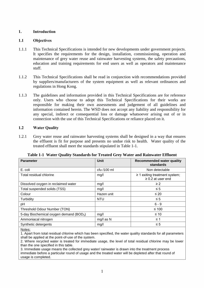
1.2.1 Grey water reuse and rainwater harvesting systems shall be designed in a way that ensures
the effluent is fit for purpose and presents no undue risk to health. Water quality of the
treated effluent shall meet the standards stipulated in Table 1-1.
Table 1-1 Water Quality Standards for Treated Grey Water and Rainwater Effluent
Parameter Unit Recommended water quality standards
E. coli cfu /100 ml Non detectable
Total residual chlorine mg/l ≥ 1 exiting treatment system; ≥ 0.2 at user end
Dissolved oxygen in reclaimed water mg/l ≥ 2
Total suspended solids (TSS) mg/l ≤ 5
Colour Hazen unit ≤ 20
Turbidity NTU ≤ 5
pH 6 - 9
Threshold Odour Number (TON) ≤ 100
5-day Biochemical oxygen demand (BOD5) mg/l ≤ 10
Ammoniacal nitrogen mg/l as N ≤ 1
Synthetic detergents mg/l ≤ 5
Notes: 1. Apart from total residual chlorine which has been specified, the water quality standards for all parameters shall be applied at the point-of-use of the system. 2. Where recycled water is treated for immediate usage, the level of total residual chlorine may be lower than the one specified in this table. 3. Immediate usage means the collected grey water/ rainwater is drawn into the treatment process immediate before a particular round of usage and the treated water will be depleted after that round of usage is completed.
2
1.2.2 Failure to meet the water quality standards, E. coli in particular, could pose undue health
risks to users. Refer to Section 7 for the required action plan should the water quality
testing result in non-compliance with the water quality standards.
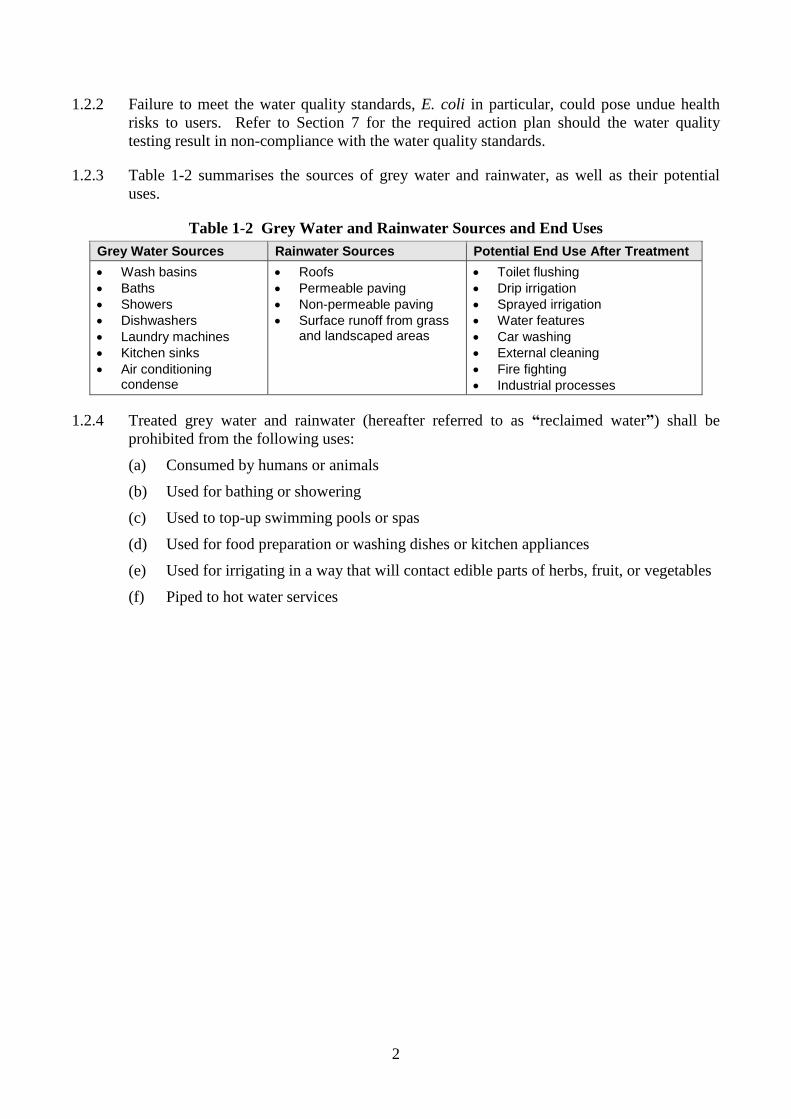
1.2.3 Table 1-2 summarises the sources of grey water and rainwater, as well as their potential
uses.
Table 1-2 Grey Water and Rainwater Sources and End Uses
Grey Water Sources Rainwater Sources Potential End Use After Treatment
Wash basins
Baths
Showers
Dishwashers
Laundry machines
Kitchen sinks
Air conditioning condense
Roofs
Permeable paving
Non-permeable paving
Surface runoff from grass and landscaped areas
Toilet flushing
Drip irrigation
Sprayed irrigation
Water features
Car washing
External cleaning
Fire fighting
Industrial processes
1.2.4 Treated grey water and rainwater (hereafter referred to as “reclaimed water”) shall be
prohibited from the following uses:
(a) Consumed by humans or animals
(b) Used for bathing or showering
(c) Used to top-up swimming pools or spas
(d) Used for food preparation or washing dishes or kitchen appliances
(e) Used for irrigating in a way that will contact edible parts of herbs, fruit, or vegetables
(f) Piped to hot water services
3
2. Design and Construction Requirements
2.1 Grey Water Collection
2.1.1 Grey water sufficient to meet the demand shall be collected in a separate drainage pipework
and allowed to flow from collection appliances to the grey water treatment system via
gravity or siphonic action. Surplus grey water shall be collected and discharged directly to
the sewer. The designers of the new sewerage system for the development and the sewerage
master plan for the district should accordingly take into account the abstraction of grey
water from the sewerage system and make appropriate adjustments to the design
assumptions so as to safeguard the self-cleansing capacity of the foul sewer and the overall
capacity in the new system, especially during the early stage of occupation where the flow
rate of sewer is low. In case the self-cleansing capacity cannot be maintained due to low
flow rate, grey water collection system shall be suspended until the flow rate reaches the
required level for self-cleansing.
2.1.2 The grey water collection pipework shall be dedicated to the following sources:
(a) Bathroom wash basins
(b) Showers and baths
2.1.3 Where additional sources of grey water are needed, the collection pipework may also collect
grey water from the following sources:
(a) Clothes washing machines/laundry water
(b) Kitchen sinks
(c) Dishwashers
(d) Air conditioning condense
2.1.4 The collection pipework shall be designed to prevent blackwater (water from toilet flushing)
from entering the grey water system.
2.1.5 To reduce the generation of foam, the grey water collection pipework should be designed to
minimise turbulence and the use of bends. It should be free draining to avoid stagnation.
Suitable non-intrusive type of flow measurement devices should also be used to avoid
blockage.
2.1.6 The collection pipework shall be properly identified and labelled in accordance with Section
8.
2.1.7 A bypass shall be installed around the grey water system allowing the collected grey water
to flow directly to the sewer during periods of maintenance or system isolation. The bypass
shall not tie into the storm drain system.
2.1.8 Flow measuring device(s) shall be provided to measure the quantity of total grey water
collected.
2.1.9 Due to water quality concerns from bacterial growth, collection systems should be designed
and constructed such that grey water reaches the treatment process as soon as possible.
Intermediate storage should be avoided.
4
2.1.10 Designers shall take into account site-specific and application-specific considerations and
make necessary adjustment to the design in this Technical Specifications.
2.2 Rainwater Collection
2.2.1 Rainwater harvesting system collection consists of:
(a) Roof catchment
(b) Gutters
(c) Downpipes
2.2.2 A grill or coarse mesh should be placed at the mouth of the drainpipe to prevent large debris
(e.g. leaves) from entering the collection system. Where gutters are present, a gutter mesh
system can be installed across the gutter section, preferably with a gradient to reduce the
need of periodic cleaning. The openings of the grill or gutter mesh should have 4 to 6mm
openings.
2.2.3 First-flush diverters, which diverts the first few minutes of rainwater away from the
collection tank, should be installed. The first few minutes of rainfall contains particulates,
debris, and contaminants such as bird and animal faeces, pesticides, pollution, roofing
material, and dissolved gasses.
2.2.4 A bypass shall be installed around the rainwater system allowing the first flush of rainwater
from each rainfall event, the collected rainwater during periods of maintenance or system
isolation and the surplus rainwater to flow directly to the storm drain system. The bypass
shall not tie into the sewer.
2.2.5 Flow measuring device(s) shall be provided to measure the quantity of rainwater collected.
2.2.6 The collection pipework shall be properly identified and labelled in accordance with Section
8.
2.2.7 Due to water quality concerns from bacterial growth, collection systems should be designed
and constructed such that rainwater reaches the treatment process as soon as possible.
Intermediate storage should be avoided.
2.2.8 Designers shall take into account site-specific and application-specific considerations and
make necessary adjustment to the design in this Technical Specifications.
2.3 Collection Tank
General
2.3.1 Most collection tanks for grey water and rainwater systems are constructed of plastics, such as
glass-reinforced polyester (GRP) or high-density polyethylene (HDPE). Collection tanks may
also be constructed of concrete or steel if these are suitably sealed and protected against the
corrosive effects of the stored water. Tanks should be lightproof to minimise algae growth.
2.3.2 Where GRP is used for construction of the collection tank, the design shall comply with
Buildings Department’s Practice Note for Authorized Persons, Registered Structural
Engineers and Registered Geotechnical Engineers – APP-100 “Structural Plans of Glass
Reinforced Polyester (GRP) Water Tanks” requirements with structural drawing and
5
calculations providing the structural integrity and safety according to Hong Kong Building
(Construction) Regulations.
2.3.3 Collection tanks should be fitted with a close-fitting, removable cover to allow for periodic
inspection and for internal cleaning and maintenance of components such as sensors and
submersible pumps. Providing a lock to the access cover is recommended to avoid
accidental entry into the tank.
2.3.4 Collection tanks and also tanks for part of the treatment process shall be water proof. If
buried, they shall be designed to resist likely ground and traffic loadings, floatation due to
hydraulic uplift forces, and groundwater ingress when empty or partially full. Ingress may
occur due to the permeability of the tank material (e.g. natural permeability of concrete as
well as potential cracks in the concrete) or due to deformation of the tank resulting from
water, soil, overburden, and traffic loading.
2.3.5 The tank should be sited so that the stored water does not attain high temperatures that could
encourage microbial growth. Above ground tanks should be opaque to minimise the
potential of warming and algae growth.
2.3.6 For buried tanks that are located in areas subject to flooding, access covers should be raised
or sealed.
2.3.7 The collection tank shall be fitted with a screened air vent to avoid build up of any noxious
gases.
2.3.8 Filter backwash is considered as foul water and should also be discharged to the foul drain
or sewer system.
2.3.9 If the collection tank is buried, or partially buried, sewage backflow into the tank can occur
in the event that the foul drain is blocked or the area becomes flooded. Therefore, sewage
backflow prevention should be included in the installation.
2.3.10 The sewage backflow prevention device should be fitted with a visible indicator which may
only be reset by manual intervention. The sewage backflow prevention device can be in the
form of a valve and a float-operated backflow detection switch in the vertical connecting
pipe to the foul drain or sewer.
2.3.11 In the event of sewage backflow, the control system should prevent the treated grey water
and rainwater from being supplied until the system has been inspected, and any necessary
remedial measures carried out and the reclaimed water quality checked.
Grey Water Collection Tank
2.3.12 Air ejector(s) should be provided in the grey water storage tank to prevent septicity.
2.3.13 Backflow prevention shall be provided to prevent highly contaminated water from re-
entering the system in the event of blockage in the foul sewer.
2.3.14 As the generation of grey water is intermittent, a buffered collection storage tank is required
to provide a relatively uniform flow through the rest of the treatment process. However, it
is advisable to minimise storage of untreated grey water to reduce the adverse effects of
stagnation and bacteria proliferation.
6
2.3.15 The grey water storage tank should be designed to store untreated flow for a period of at
least two hours, but no more than twenty-four hours. For most applications, the tank may
be sized to provide 8 to 10 hours of storage.
2.3.16 The methodology of calculating grey water supply and demand is presented in Section 3.
2.3.17 Grey water collection tanks shall overflow to the sewer system. In addition, a drain is
required at the bottom of the collection tank to allow solids that have settled out of the grey
water to be collected into a sludge storage tank.
Rainwater Collection Tank
2.3.18 Backflow prevention shall be provided to prevent highly contaminated water from re-
entering the system in the event of blockage in the storm drainage system.
2.3.19 A calming inlet is recommended for rainwater collection tanks. A calming inlet prevents the
disturbance and re-suspension of fine sediments that may gather on the tank floor and
introduces oxygen to the lower layers of the tank which helps prevent anaerobic conditions.
2.3.20 The rainwater collection tank may be stored for 10 to 20 days of supply. An important
consideration is space availability.
2.3.21 The methodology of calculating rainwater supply is presented in Section 3.
2.3.22 Assuming that space availability is not an issue, the following three scenarios should be
considered:
(a) Insufficient rainwater collected to meet the demands of the potential applications.
This is likely the case for the majority of installations in Hong Kong where there are
multi-story buildings with many occupants. Tank sizing will be governed by the
rainfall and catchment area. The tank size should be based on an evaluation of the
rainwater likely to be collected from statistical rainfall patterns, catchment area, and
filtration coefficients minus the average use, and also the amount of grey water that
may be available.
(b) Excessive rainwater collected to meet the demands of the potential applications during
wet weather months. This may be the case for commercial and industrial installations.
Tank sizing should be governed by the rate of use, according to the level of demand
and the required number of days of assured supply.
(c) A rough balance between the rainwater collected and the demands of the potential
applications during wet weather months. The tank should be sized sufficiently large
such that it does not frequently overflow but not so large that it causes stagnation or is
unnecessarily expensive.
2.3.23 Rainwater collection tanks shall overflow to a stormwater drain and not to a foul sewer.
2.4 Grey Water Treatment
2.4.1 Grey water treatment shall consist of the following components:
(a) Pre-treatment
(b) Biological treatment
(c) Filtration
7
(d) Disinfection
2.4.2 Pre-treatment shall include a fine/mesh screen to remove hair, soap, and other particulate
matter in the grey water. The screen shall have a spacing of 2 mm.
2.4.3 Where grey water is collected from kitchen sinks and dishwashers, pre-treatment shall also
include an oil and grease trap. An automatic oil and grease trap, where the oil is skimmed
out automatically using a timer or sensor mechanism, shall be used.
2.4.4 The fine/mesh screen shall preferably be of the self-cleaning type to reduce the reliance on
the user cleaning the screen to maintain system performance.
2.4.5 Biological treatment shall be included to remove organic matter and other pollutants in the
grey water. The most common types of biological treatment are biological aerated filter
(BAF), rotating biological contactor (RBC), and sequencing batch reactors (SBR).
2.4.6 Filtration shall be included and shall be able to meet the required effluent turbidity of equal
or less than 5 NTU. Many types of filters are commercially available, including sand and
mechanical. Membrane filtration, such as microfiltration (MF) and ultrafiltration (UF) may
also be used in place of the conventional filters. They are capable of achieving high effluent
quality standards on a small footprint.
2.4.7 The membrane bioreactor (MBR), a hybrid treatment process that combines biological
treatment and membrane filtration into one system, may be used in place of the biological
and filtration components.
2.4.8 Disinfection is required as the final treatment step. The reclaimed water quality criteria
stipulate a total chlorine residual equal to or greater than 0.2 mg/l at the end of the
distribution system.
2.4.9 Disinfection may utilise chlorine disinfection which may be achieved by using a sodium
hypochlorite system. Chlorine tablets may be used for smaller systems. A separate
disinfection contact chamber of a size to allow a minimum of 30-minute contact time at
peak flow for disinfection is required.
2.4.10 UV disinfection may be used. However, as it does not produce any disinfectant residual in
the treated effluent, the treated water shall be used immediately, i.e. the collected water shall
be drawn into the treatment process immediate before a particular round of usage and such
treated water shall be depleted after that round of usage is completed.
2.4.11 Where the treated water by UV disinfection is to be stored for future use, it must be
supplemented with chlorine disinfection to provide the necessary residual chlorine. Simple
metering and control devices dosing industrial bleach can effectively supplement the
adequate amount of residual chlorine to meet the water quality standards.
2.4.12 Alternatively, for small scale systems (daily consumption <5m3), the chlorine supplement
can be provided by using household bleach. Common household bleach contains about
5.25% sodium hypochlorite solution which is equivalent to approximately 20mg of chloride
ion per litre. Household bleach can be mixed into the reclaimed water at a ratio of 1:20000,
i.e. 50ml of household bleach per 1 m3, or 1000 litre, of reclaimed water to supplement the
required level of residual chlorine. Field testing shall however be conducted to determine
the exact ratio for correct dosage.
8
2.4.13 Flow measuring device(s) shall be provided to measure the total quantity of all grey water
treated.
2.4.14 The system supplier shall select the most appropriate process to meet the required water
quality requirements.
2.4.15 The treatment system shall be capable of connection to the sewer such that:
(a) An overflow to the environment will not occur should there be a failure of the
treatment system.
(b) The operator may direct grey water to the sewer during periods of rain or other
circumstances adverse to the discharge of treated greywater into the reuse distribution
system.
2.4.16 The treatment system shall be designed to perform continuously and without any
interventions between specified inspection intervals performed by the maintenance
contractor.
2.4.17 The treatment system shall be constructed in accordance with the design specifications and
in accordance with good trade practices so as to allow ease of access for maintenance and
with regard to the health and safety of users, operators, and persons maintaining the facility.
2.4.18 The treatment system shall be clearly marked with the brand name, model, and month and
year of manufacture which should be clearly visible after installation.
2.4.19 All metal components shall be of stainless steel or other non-corroding material unless
adequately protected against corrosion to satisfy the service life of the component.
2.4.20 All plastics and perishable components in the treatment system subject to exposure to ultra-
violet radiation, or an adverse chemical or biological environment shall be able to retain
their integrity under normal operating conditions to satisfy the service life of the component.
2.4.21 All components shall be securely fixed to withstand all loads encountered during
transportation, installation, and normal operation.
2.4.22 Unless specifically designed to operate in a submerged condition, all mechanical and
electrical equipment when located within the treatment system vessel(s) shall be located
above the maximum water level of the treatment system.
2.5 Rainwater Treatment
2.5.1 Rainwater treatment shall consist of the following components:
(a) Pre-treatment
(b) Filtration
(c) Disinfection
2.5.2 Pre-treatment shall include a first-flush removal device and oil trap.
2.5.3 The two most common types of first-flush device are of constant volume and mechanical
actuated valve.
9
2.5.4 A constant volume first-flush device uses a containment chamber that fills up during the
first few minutes of a rain storm. The containment chamber is a container or a stand pipe
with a constant volume. During the first few minutes of rainfall, the rainwater is diverted to
the stand pipe or container. Once the stand pipe or container fills up, the rainwater is
transferred into the cistern. At the bottom of the stand pipe is a valve that is slightly opened.
The valve drains the water from the stand pipe so it will be empty for the next rain.
2.5.5 A mechanical actuated valve first-flush device measures the amount of rainwater to divert
by a mechanical method. Once the measured amount of rainwater to divert is detected, a
valve is triggered to transfer the remaining rainwater to the rainwater storage tank.
2.5.6 An automatic oil trap, where the oil is skimmed out automatically using a timer or sensor
mechanism, shall be used for rainwater collected from driveways, car parks, etc.
2.5.7 Coarse filtration followed by sand filtration (or cartridge filtration) and granular activated
carbon filtration (GAC) shall be used as follows:
(a) The coarse filter shall be rated at 250 micron or smaller to remove large particulate
matter.
(b) The sand filter or cartridge filter shall be rated at 50 micron or smaller.
(c) GAC filtration shall be used to remove smaller particulate matter and hydrocarbons.
2.5.8 An option for coarse filtration is available where the filter is installed inside the rainwater
collection pipe prior to entering the storage tank.
2.5.9 Disinfection is required as the final treatment step. The reclaimed water quality criteria
stipulate a total chlorine residual equal to or greater than 0.2 mg/l at the end of the
distribution system.
2.5.10 Disinfection may utilise chlorine disinfection which may be achieved by using a sodium
hypochlorite system. Chlorine tablets may be used for smaller systems. A separate
disinfection contact chamber of a size to allow a minimum of 30-minute contact time at
peak flow for disinfection is required.
2.5.11 UV disinfection may be used. However as it does not produce any disinfectant residual in
the treated effluent, the treated water shall be used immediately, i.e. the collected water shall
be drawn into the treatment process immediate before a particular round of usage and such
treated water shall be depleted after that round of usage is completed.
2.5.12 Where the treated water by UV disinfection is to be stored for future use, it must be
supplemented with chlorine disinfection to provide the necessary residual chlorine. Simple
metering and control devices dosing industrial bleach can effectively supplement the
adequate amount of residual chlorine to meet the water quality standards.
2.5.13 Alternatively, for small scale systems (daily consumption <5m3), the chlorine supplement
can be provided by using household bleach. Common household bleach contains about
5.25% sodium hypochlorite solution which is equivalent to approximately 20mg of chloride
ion per litre. Household bleach can be mixed into the reclaimed water at a ratio of 1:20000,
i.e. 50ml of household bleach per 1 m3, or 1000 litre, of reclaimed water to supplement the
required level of residual chlorine. Field testing shall however be conducted to determine
the exact ratio for correct dosage.
10
2.5.14 Flow measuring device(s) shall be provided to measure the total quantity of all rainwater
treated.
2.5.15 The system supplier shall select the most appropriate process to meet the required water
quality requirements.
2.5.16 The treatment system shall be designed to perform continuously and without any
interventions between specified inspection intervals performed by the maintenance
contractor.
2.5.17 The treatment system shall be constructed in accordance with the design specifications and
in accordance with good trade practices so as to allow ease of access for maintenance and
with regard to the health and safety of users, operators, and persons maintaining the facility.
2.5.18 The treatment system shall be clearly marked with the brand name, model, and month and
year of manufacture which should be clearly visible after installation.
2.5.19 All metal components shall be of stainless steel or other non-corroding material unless
adequately protected against corrosion to satisfy the service life of the component.
2.5.20 All plastics and perishable components in the treatment system subject to exposure to ultra-
violet radiation, or an adverse chemical or biological environment shall be able to retain
their integrity under normal operating conditions to satisfy the service life of the component.
2.5.21 All components shall be securely fixed to withstand all loads encountered during
transportation, installation, and normal operation.
2.5.22 Unless specifically designed to operate in a submerged condition, all mechanical and
electrical equipment when located within the treatment system vessel(s) shall be located
above the maximum water level of the treatment system.
2.6 Combined Treatment for Grey Water and Rainwater
2.6.1 For installations with both grey water and rainwater, the two streams may be combined such
that they produce a single supply of treated water. The rainwater stream may be sent to the
grey water treatment system for combined treatment via conveyance from the rainwater
storage tank to the grey water collection tank. This is illustrated in the schematic diagram in
Figure 14-1.
2.6.2 During the dry months from October to March, the rainwater system may be shut down.
During these months, any rainfall collected from the rainwater collection system may be
bypassed directly to the head of the grey water treatment system. The collected rainwater
should be metered.
2.7 Storage
2.7.1 For grey water and rainwater systems in Hong Kong, where the point of use is for landscape
irrigation, water features, car washing, etc., storage tanks for the reclaimed water are usually
located near the ground floor.
2.7.2 For applications where the reclaimed water needs to be supplied to higher elevations, e.g.,
toilet flushing, high level tanks are utilised.
11
2.7.3 The tank should be sited so that the stored water does not attain high temperatures that could
encourage microbial growth. Above ground tanks should be opaque to minimise the
potential of warming and algae growth.
2.7.4 Below ground tanks should be sufficiently rigid to resist likely ground and traffic loadings
and floatation.
2.7.5 A back-up water supply, such as potable mains water supply, is required to supplement the
reclaimed water as specified in Section 2.14. Backflow prevention device shall be provided
as specified in Section 2.15.
2.7.6 The impact of a sudden demand from the back-up water supply should be considered. It is
essential that the potable water supply infrastructure is capable of meeting this increase in
water demand.
2.7.7 To avoid microbiological growth and bacteria proliferation in the reclaimed water storage
tank, the storage time should be limited. This is especially important in Hong Kong’s high
temperature climates. As there is generally a steady supply of untreated grey water, storage
equal to a single day’s use (24 hours) is recommended.
2.8 Pumps
2.8.1 Most grey water and rainwater systems locate their collection tanks at or below ground
level, and treated effluent is pumped into a building or elsewhere.
2.8.2 Some grey water and rainwater systems omit the cistern component and provide a
pressurised reclaimed water supply directly from the pump to point of use. In the event of
pump or power failure, such direct supply systems will not supply reclaimed water to points
of use. Mains make-up water pipework to the direct supply system should be installed with
backflow prevention in conformance to the Waterworks Ordinance and Regulations. This is
required at each application point served with both reclaimed and mains water.
2.8.3 The pumps should be corrosion resistant and properly selected to pump to the required head
to fill the cistern or supply adequate flow if pumped directly to the point of use.
Submersible pumps and external self-priming pumps are typical.
2.8.4 Pumps should be protected from dry running. A low level switch in the collection tank
should be used. To prevent overheating or burn out of the pump, the level should be set
such that the pump does not continually switch on and off due to small and infrequent
inflow of source water.
2.8.5 Pumps should be sized so that each pump is capable of overcoming static lift plus friction
losses in the pipework and valves.
2.8.6 Pumps should be selected and arranged such as energy use and noise are minimised,
cavitation is avoided, and air is not introduced into the grey water and rainwater system.
2.8.7 Pumps for untreated grey water should be able to accommodate any solid matter likely to be
contained in the grey water.
12
2.8.8 For reclaimed water pumping systems that are installed outside the storage tank, the pump
should have its own self-priming mechanism or a control system that ensures a constant
fully primed condition. The suction line to the pump should be laid with a steady gradient
upwards towards the pump. The pump should be placed in a well-ventilated location and
protected from extremes of temperature, with sound-free and vibration-free mountings.
2.8.9 A non-return valve should be provided in the suction line to the pump to prevent the water
column from draining down. The pump discharge should be supplied with an isolation
valve.
2.8.10 For submersible pumping systems, the immersion depth should be in accordance with the
pump manufacturer’s requirements. The pump should be removable for maintenance. A
non-return valve should be provided, with an isolation valve to enable the non-return valve
to be serviced.
2.8.11 The pump control unit should operate the pump(s) to match demand; protect the pumps
from running dry; protect the motor from over-heating and electric overload; and permit
manual override.
2.9 Mechanical Equipment
2.9.1 All mechanical equipment shall be suitable for continuous and intermittent operation.
2.9.2 Bearings shall be of a type able to provide long life, minimal maintenance, and corrosion
protection from the aggressive environment.
2.10 Electrical Equipment
2.10.1 All electrical equipment shall be suitable for continuous and intermittent operation.
2.10.2 Electric motors shall comply with the relevant electrical standards and be fitted with thermal
overload devices. Where there is any possibility of an explosive gas mixture developing
near a motor, the motor shall be intrinsically safe.
2.10.3 The treatment system shall be provided with a control panel that indicates the following as a
minimum:
a) indication that system is operating correctly
b) alarms indicating failure of components including identification of component (e.g.
pump, level control, chemicals, UV)
c) levels in all tanks
d) power supply status
e) flows
f) operating hours (preferably records of on/off cycles combined with flows)
g) chemical supply levels
h) chemical usage
i) automatic control of the alternative water supply to meet variations in supply and
demand
j) water quality parameters that can be detected on a continuous basis e.g. pH, total
residual chlorine, temperature, turbidity, dissolved oxygen and possibly ammonia
k) supply delivery pressure where a pumped system is used
13
l) on-line monitoring results for surveillance on the quality of treated effluent (if on-line
monitors are available).
2.10.4 The treatment system shall be fail-safe such that untreated water cannot be supplied to
points of use in the event of system failure, including loss of power and loss of disinfection.
A fail-safe condition should occur if any essential part of the system ceases to operate.
2.11 Noise
2.11.1 The maximum permissible noise level with all operating equipment shall comply with
relevant noise criteria.
2.12 Materials and Fittings
2.12.1 Collection and distribution pipework and fittings should be constructed from corrosion
resistant components such as high density polyethylene (HDPE), poly-vinyl chloride (PVC),
or ABS plastic. Copper and galvanised steel pipes are not recommended, although cast iron
or ductile iron may be considered for buried piping if ground conditions do not suit the use
of plastics.
2.12.2 The materials selected for the rainwater harvesting and grey water systems shall be suitable
for the location and anticipated temperature ranges. All components of the grey water
system shall be capable of withstanding pH levels as low as 5 for the lifetime of the
components.
2.13 Power Supply
2.13.1 The power supply shall be readily accessible but also guarded to ensure against inadvertent
isolation or disconnection of electricity.
2.14 Back-up Water Supply
2.14.1 An alternative water supply, such as potable mains water supply, is required as a back-up
water supply to supplement the reclaimed water. The back-up water supply may be
introduced into the following:
(a) The treated grey water and rainwater storage tank
(b) An intermediate storage tank prior to pumping to the reclaimed water distribution
system
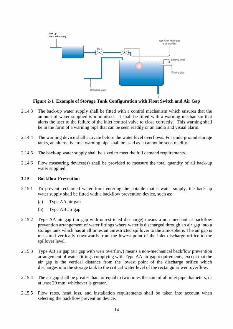
2.14.2 A float switch located inside the storage tank shall be used to activate the back-up water
supply when the water level in the storage tank reaches a low level. The float switch shall
turn off the back-up water supply at a pre-set level to leave space for incoming reclaimed
water. An example is shown in Figure 2-1.
14
Figure 2-1 Example of Storage Tank Configuration with Float Switch and Air Gap
2.14.3 The back-up water supply shall be fitted with a control mechanism which ensures that the
amount of water supplied is minimised. It shall be fitted with a warning mechanism that
alerts the user to the failure of the inlet control valve to close correctly. This warning shall
be in the form of a warning pipe that can be seen readily or an audio and visual alarm.
2.14.4 The warning device shall activate before the water level overflows. For underground storage
tanks, an alternative to a warning pipe shall be used as it cannot be seen readily.
2.14.5 The back-up water supply shall be sized to meet the full demand requirements.
2.14.6 Flow measuring devices(s) shall be provided to measure the total quantity of all back-up
water supplied.
2.15 Backflow Prevention
2.15.1 To prevent reclaimed water from entering the potable mains water supply, the back-up
water supply shall be fitted with a backflow prevention device, such as:
(a) Type AA air gap
(b) Type AB air gap
2.15.2 Type AA air gap (air gap with unrestricted discharge) means a non-mechanical backflow
prevention arrangement of water fittings where water is discharged through an air gap into a
storage tank which has at all times an unrestricted spillover to the atmosphere. The air gap is
measured vertically downwards from the lowest point of the inlet discharge orifice to the
spillover level.
2.15.3 Type AB air gap (air gap with weir overflow) means a non-mechanical backflow prevention
arrangement of water fittings complying with Type AA air gap requirements, except that the
air gap is the vertical distance from the lowest point of the discharge orifice which
discharges into the storage tank to the critical water level of the rectangular weir overflow.
2.15.4 The air gap shall be greater than, or equal to two times the sum of all inlet pipe diameters, or
at least 20 mm, whichever is greater.
2.15.5 Flow rates, head loss, and installation requirements shall be taken into account when
selecting the backflow prevention device.
15
2.15.6 The backflow prevention device shall be located upstream or, or at the point of delivery
where the two supplies come into contact with each other.
2.16 Overflow, Bypass, and Drainage
2.16.1 An overflow shall be fitted to all tanks or cisterns to allow excess water to be discharged.
The overflow shall incorporate backflow prevention. An overflow fitted to aboveground
tanks or cisterns shall be screened to prevent the ingress of insects and rodents.
2.16.2 The capacity of the overflow outlet pipe shall be capable of draining the maximum inflow
without compromising the inlet air gap.
2.16.3 Where appropriate, the overflow and bypass shall be fitted with an anti-surcharge valve.
2.16.4 The overflow and any bypass of the grey water system shall be connected to the foul sewer.
2.16.5 The overflow and any bypass of the rainwater system shall be connected to the storm drain
system.
2.16.6 Any discharge to drain from the grey water system shall minimise the volume of foam
introduced to the drainage system and shall be properly dechlorinated.
2.16.7 Flow measuring devices(s) shall be provided to measure the total quantity of all grey water
and rainwater down the overflow, bypass and drainage system.
2.16.8 The discharge of any surplus grey water or rainwater as well as backwash water shall be
made at a location that would not overload the downstream carrying capacity of their
respective receiving sewerage or storm drain systems.
2.17 Controls
2.17.1 A control unit shall be incorporated in the grey water and rainwater systems to ensure that
users are aware of whether the systems are operating effectively.
2.17.2 The control unit shall:
(a) Make the user aware when any consumable items need replenishment or replacement
(b) In the event of any system failure:
(i) Alert the user by a visible or audible warning;
(ii) Ensure that the bypass directs untreated grey water to the foul sewer, and
untreated rainwater to the storm sewer;
(iii) Ensure that grey water and rainwater treatment continue or that treated grey
water and rainwater are not stored for a period that would allow water quality
to deteriorate
(c) In the event of a treatment failure, ensure that the reclaimed water applications are fed
from the back-up water supply
(d) Control pumps and minimise operational wear and energy use
(e) Activate the back-up water supply automatically when required by the control unit
(f) Provide a volt-free output to enable the grey water and rainwater systems to be linked
to a building management system, where appropriate
16
2.17.3 To prevent waste, storage tanks or cisterns with valve-controlled water inputs shall have a
warning system so that any failure is readily noticeable.
2.18 Sludge Holding Tank
2.18.1 A sludge holding tank is necessary to provide temporary storage of sludge produced by the
biological treatment component of the grey water treatment system.
2.18.2 Wet sludge should be hauled off to the local municipal sewage treatment works on a
periodic basis.
2.18.3 The sizing of the sludge holding tank depends on the biological process and influent
characteristics of the grey water. Without any specific information, the tank can be sized
based on 7 hours of hydraulic residence time of the grey water design flow. For example, if
the design flow is 100 m3/day, the volume of the tank can be calculated as shown below:
7 hours x 1 day/24 hours x 100 m3/day = 29 m
3
2.18.4 An aerator should be provided for the sludge holding tank to prevent septicity.
2.18.5 Vehicular access should be maintained for desludging tankers.
2.19 Location and Access of Treatment Systems
2.19.1 Treatment systems for grey water and rainwater are likely to be located at ground level or
below.
2.19.2 Proper access for maintenance will ensure safe and efficient operation of the system. The
treatment system will need periodic access to maintain pumps, change filters, and cleaning.
Easy access around collection and treatment tanks should be provided, including sealed but
not airtight man-sized access ports for all but the smallest tanks (e.g. 1 m3 or smaller).
2.19.3 Access to the treatment room(s) should be restricted and secured from public access for
safety reasons.
2.19.4 Regarding the location of the grey water collection tank, the prevention of sewer backflow
should be taken into consideration, including the minimum vertical separation between the
overflow and sewer pipe. The tank should not be located directly above drainage pipes or
other buried services. The tank should be vented to the atmosphere, either via the grey
water drain and stack, or with a stub-vent from the tank.
2.20 Distribution
2.20.1 Treated grey water and rainwater shall be distributed by:
(a) Pumping from the storage tank directly to the point of use
(b) Pumping from the storage tank to intermediate storage tanks or cisterns near the
point(s) of use
(c) Supplying by a gravity storage tank or cistern, where feasible
2.20.2 Distribution systems should be designed and constructed such that the overall storage time
of reclaimed water does not result in unacceptable reduction in water quality. Header tanks
for toilet flushing should not be oversized. Dead zones in the distribution piping should be
17
avoided to prevent bacteria proliferation. For lengthy distribution systems, consideration
should be given to recirculation of a small flow of the treated effluent to the treatment
process to avoid stagnation.
2.20.3 There are no fundamental differences between the design of reclaimed water and mains
water distribution systems, though the pipework and materials for the reclaimed water
system should be chosen for resistance to corrosion.
2.20.4 Care should be taken not to cross connect reclaimed water and mains water pipework during
installation or subsequent work on the system. Pipe marking is essential to help avoid
accidental cross-connection.
2.20.5 All pipework and fittings shall be marked and/or labelled in accordance with Section 8.
2.20.6 To avoid accidental cross contamination, the reclaimed water system should operate at a
lower pressure than the potable water mains supply.
2.20.7 Consideration should be given to minimising the energy used to distribute the reclaimed
water.
2.20.8 Surges and water hammer should be absorbed and prevented from causing undue high
pressures by the incorporation of pressure controls or expansion vessels.
2.20.9 Pipework should be sized to provide adequate flow and pressure.
2.20.10 Pipework and fittings should be arranged as follows:
(a) To be sufficiently strong to resist bursting from the subjected pressure in operation
(b) To prevent cross-connections with potable mains water supply
(c) To prevent the trapping of air during filling, and the formation of air locks during
operation
2.20.11 For multiple building scale schemes and larger configurations, disconnection from the
system should be considered. This may be required where a building opts out of a
communal grey water reuse scheme, or persistently provides grey water of a quality which
would be detrimental to the overall performance of the system, such as highly contaminated
or strongly coloured grey water.
2.20.12 Disconnection of grey water collection should be as close as possible to the source and the
downstream pipework should be drained. Retention of stagnant grey water in any part of
the system should be avoided. Temporary disconnection of collection may be provided by a
lockable valve or a plug. Permanent disconnection should include physically removing a
pipe section and sealing the open ends.
18
3. Methodology in Assessing Quantity of Supply and Demand
3.1 Introduction
3.1.1 This section presents the methodology for estimating the quantity of grey water and
rainwater supply and demand.
3.2 Rainwater Yield
3.2.1 The amount of rainwater retrieved can be estimated from the following equation:
Yr = Ac x Rm x Cr
where:
Yr is the weekly average rainwater yield (litre/week)
Ac is the collection area (m2)
Rm is the average weekly rainfall (mm)
Cr is the run-off coefficient
If an in-line filter is installed to the rainwater collection system, a filter efficiency, Nf,
should be incorporated into the above equation. Typically, a vertical inline filter has a value
of 0.9.
3.2.2 The collection area is the plan area (rather than the slope area) available for rainwater
collection. Possible collection areas include roofs of buildings, open spaces such as
playgrounds, or sky gardens at mid-level of buildings. Car parking lots and roads within the
development may also serve as part of the collection area.
3.2.3 Average weekly rainfall of 80mm may be used, as derived from rainfall record of Hong
Kong Observatory.
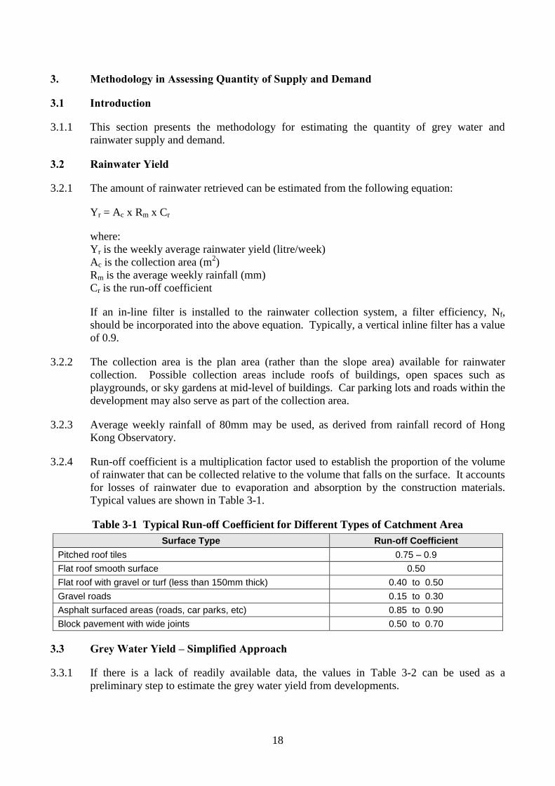
3.2.4 Run-off coefficient is a multiplication factor used to establish the proportion of the volume
of rainwater that can be collected relative to the volume that falls on the surface. It accounts
for losses of rainwater due to evaporation and absorption by the construction materials.
Typical values are shown in Table 3-1.
Table 3-1 Typical Run-off Coefficient for Different Types of Catchment Area
Surface Type Run-off Coefficient
Pitched roof tiles 0.75 – 0.9
Flat roof smooth surface 0.50
Flat roof with gravel or turf (less than 150mm thick) 0.40 to 0.50
Gravel roads 0.15 to 0.30
Asphalt surfaced areas (roads, car parks, etc) 0.85 to 0.90
Block pavement with wide joints 0.50 to 0.70
3.3 Grey Water Yield – Simplified Approach
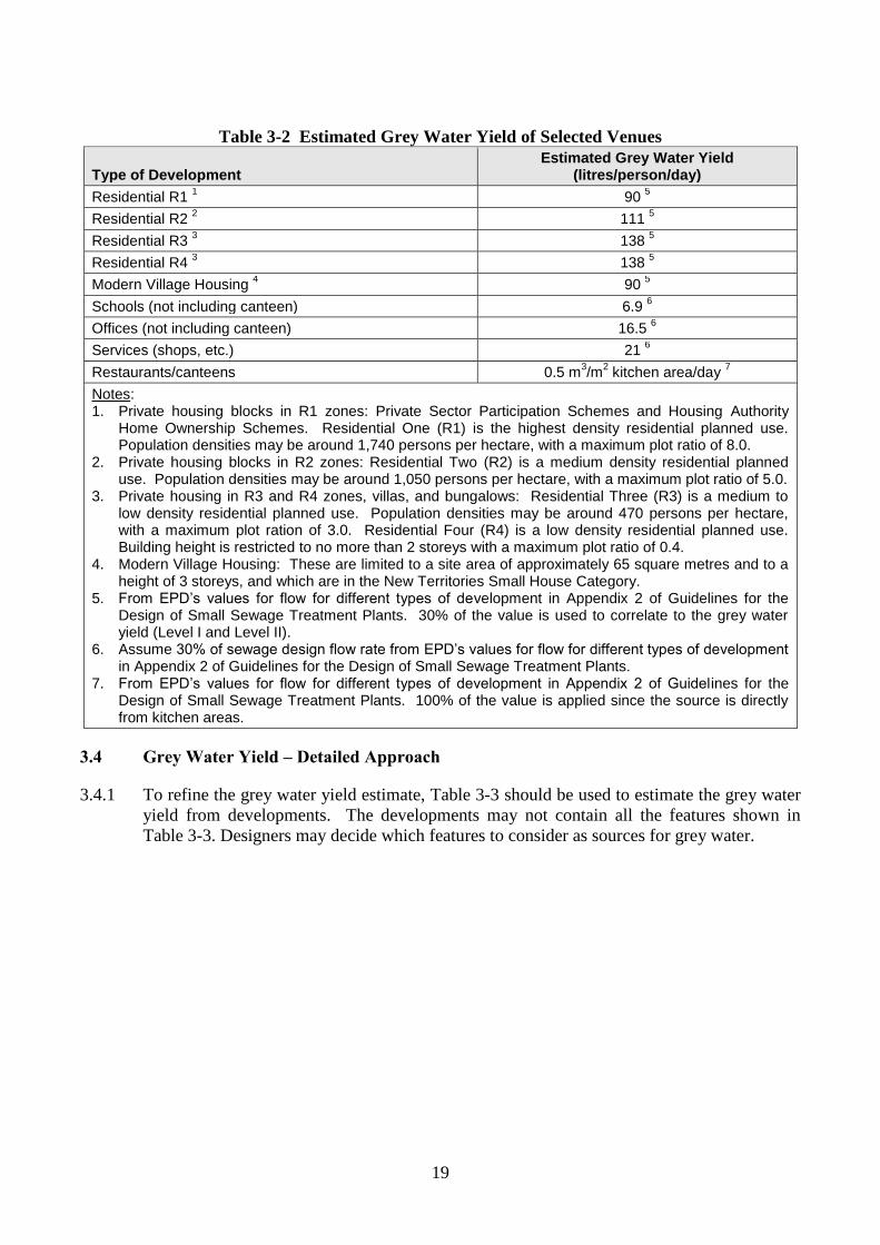
3.3.1 If there is a lack of readily available data, the values in Table 3-2 can be used as a
preliminary step to estimate the grey water yield from developments.
19
Table 3-2 Estimated Grey Water Yield of Selected Venues
Type of Development Estimated Grey Water Yield
(litres/person/day)
Residential R1 1 90
5
Residential R2 2 111
5
Residential R3 3 138
5
Residential R4 3 138
5
Modern Village Housing 4 90
5
Schools (not including canteen) 6.9 6
Offices (not including canteen) 16.5 6
Services (shops, etc.) 21 6
Restaurants/canteens 0.5 m3/m
2 kitchen area/day
7
Notes: 1. Private housing blocks in R1 zones: Private Sector Participation Schemes and Housing Authority
Home Ownership Schemes. Residential One (R1) is the highest density residential planned use. Population densities may be around 1,740 persons per hectare, with a maximum plot ratio of 8.0.
2. Private housing blocks in R2 zones: Residential Two (R2) is a medium density residential planned use. Population densities may be around 1,050 persons per hectare, with a maximum plot ratio of 5.0.
3. Private housing in R3 and R4 zones, villas, and bungalows: Residential Three (R3) is a medium to low density residential planned use. Population densities may be around 470 persons per hectare, with a maximum plot ration of 3.0. Residential Four (R4) is a low density residential planned use. Building height is restricted to no more than 2 storeys with a maximum plot ratio of 0.4.
4. Modern Village Housing: These are limited to a site area of approximately 65 square metres and to a height of 3 storeys, and which are in the New Territories Small House Category.
5. From EPD’s values for flow for different types of development in Appendix 2 of Guidelines for the Design of Small Sewage Treatment Plants. 30% of the value is used to correlate to the grey water yield (Level I and Level II).
6. Assume 30% of sewage design flow rate from EPD’s values for flow for different types of development in Appendix 2 of Guidelines for the Design of Small Sewage Treatment Plants.
7. From EPD’s values for flow for different types of development in Appendix 2 of Guidelines for the Design of Small Sewage Treatment Plants. 100% of the value is applied since the source is directly from kitchen areas.
3.4 Grey Water Yield – Detailed Approach
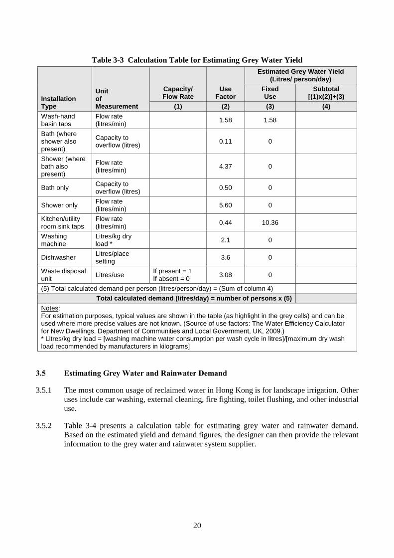
3.4.1 To refine the grey water yield estimate, Table 3-3 should be used to estimate the grey water
yield from developments. The developments may not contain all the features shown in
Table 3-3. Designers may decide which features to consider as sources for grey water.
20
Table 3-3 Calculation Table for Estimating Grey Water Yield
Installation Type
Unit of Measurement
Capacity/ Flow Rate
Use Factor
Estimated Grey Water Yield (Litres/ person/day)
Fixed Use
Subtotal [(1)x(2)]+(3)
(1) (2) (3) (4)
Wash-hand basin taps
Flow rate (litres/min)
1.58 1.58
Bath (where shower also present)
Capacity to overflow (litres)
0.11 0
Shower (where bath also present)
Flow rate (litres/min)
4.37 0
Bath only Capacity to overflow (litres)
0.50 0
Shower only Flow rate (litres/min)
5.60 0
Kitchen/utility room sink taps
Flow rate (litres/min)
0.44 10.36
Washing machine
Litres/kg dry load *
2.1 0
Dishwasher Litres/place setting
3.6 0
Waste disposal unit
Litres/use If present = 1 If absent = 0
3.08 0
(5) Total calculated demand per person (litres/person/day) = (Sum of column 4)
Total calculated demand (litres/day) = number of persons x (5)
Notes: For estimation purposes, typical values are shown in the table (as highlight in the grey cells) and can be used where more precise values are not known. (Source of use factors: The Water Efficiency Calculator for New Dwellings, Department of Communities and Local Government, UK, 2009.) * Litres/kg dry load = [washing machine water consumption per wash cycle in litres]/[maximum dry wash load recommended by manufacturers in kilograms]
3.5 Estimating Grey Water and Rainwater Demand
3.5.1 The most common usage of reclaimed water in Hong Kong is for landscape irrigation. Other
uses include car washing, external cleaning, fire fighting, toilet flushing, and other industrial
use.
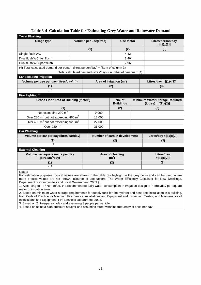
3.5.2 Table 3-4 presents a calculation table for estimating grey water and rainwater demand.
Based on the estimated yield and demand figures, the designer can then provide the relevant
information to the grey water and rainwater system supplier.
21
Table 3-4 Calculation Table for Estimating Grey Water and Rainwater Demand
Toilet Flushing
Usage type Volume per use(litres) Use factor Litres/person/day =[(1)x(2)]
(1) (2) (3)
Single-flush WC 4.42
Dual flush WC, full flush 1.46
Dual flush WC, part flush 2.96
(4) Total calculated demand per person (litres/person/day) = (Sum of column 3)
Total calculated demand (litres/day) = number of persons x (4)
Landscaping Irrigation
Volume per use per day (litres/day/m2) Area of irrigation (m
2) Litres/day = [(1)x(2)]
(1) (2) (3)
7 1
Fire Fighting 2
Gross Floor Area of Building (meter2)
No. of
Buildings Minimum Water Storage Required
(Litres) = [(1)x(2)]
(1) (2) (3)
Not exceeding 230 m2 9,000
Over 230 m2 but not exceeding 460 m
2 18,000
Over 460 m2 but not exceeding 920 m
2 27,000
Over 920 m2 36,000
Car Washing
Volume per car per day (litres/car/day) Number of cars in development Litres/day = [(1)x(2)]
(1) (2) (3)
6 3
External Cleaning
Volume per square metre per day (litres/m
2/day)
Area of cleaning (m
2)
Litres/day = [(1)x(2)]
(1) (2) (3)
1 4
Notes: For estimation purposes, typical values are shown in the table (as highlight in the grey cells) and can be used where more precise values are not known. (Source of use factors: The Water Efficiency Calculator for New Dwellings, Department of Communities and Local Government, 2009.) 1. According to TIP No. 10/05, the recommended daily water consumption in irrigation design is 7 litres/day per square meter of irrigation area. 2. Based on minimum water storage requirements for supply tank for fire hydrant and hose reel installation in a building, from Code of Practice for Minimum Fire Service Installations and Equipment and Inspection, Testing and Maintenance of Installations and Equipment, Fire Services Department, 2005. 3. Based on 2 litres/person /day and assuming 3 people per vehicle. 4. Based on using a high pressure sprayer and assuming street washing frequency of once per day.
22
4. Installation
4.1 General
4.1.1 Installation should be carried out in accordance with instructions given by the manufacturer
or supplier.
4.1.2 Consideration should be given to the following:
(a) Access to the grey water and rainwater treatment equipment
(b) Access to underground and aboveground tanks
(c) Location of access covers
(d) Vehicular access to the treatment systems
4.2 Tank Installation
4.2.1 All tanks should be fitted with lids that protect the water from contamination and prevent
inadvertent human entry.
4.2.2 Any openings to be cut in a tank, other than those provided by the manufacturer, should be
round, so as not to cause any additional stress on the tank that might result in a split. Where
non-circular openings are unavoidable, stress relief should be applied to the cut to minimise
any risk of splitting.
4.2.3 Aboveground tanks should not be supported by pipework but should be securely mounted
and supported on a stable base.
4.2.4 Aboveground tanks to be installed within a building should be able to withstand any
temporary deformation that is required during installation.
4.2.5 Underground or partially buried tanks should be so installed that they are not deformed or
damaged.
4.2.6 Measures should be taken to ensure the structural stability of underground tanks. Examples
of measures include concrete surrounds, backfilling, and/or controlled filling with water.
4.2.7 The area around the access covers of any underground tanks should be impervious and free
draining away from the covers to avoid contamination during maintenance and inspections.
4.2.8 When installed and correctly supported, tanks should not deform as the water level in the
tank changes.
4.3 Cistern Installation
4.3.1 Where reclaimed water storage cisterns are used within buildings, they should be installed
with appropriate support, insulation, and means to prevent contamination. The cistern
should be supported on a firm level base capable of withstanding the weight of the cistern
when completely filled with water. Plastic cisterns should be supported on a flat rigid
platform fully supporting the bottom of the cistern over the whole of its area.
4.3.2 An automatic supply cut-off device activated by an overflow may be installed to minimise
water wastage.
23
5. Testing, Commissioning and Decommissioning
5.1 Commissioning Procedures
5.1.1 For all schemes, the manufacturer or system supplier must provide detailed guidance on
commissioning procedures. Commissioning will typically be carried out by the
manufacturer, system supplier or its representative who has received appropriate training
and has the necessary sampling and testing equipment to verify correct operation of the
system.
5.1.2 Commissioning procedures should be system specific. The procedures generally include the
following steps:
(a) Visual check of the pipework systems. Verify that actual equipment and pipe layout
matches the schematic and that all pipes are properly identified and labelled.
(b) Verify overall system integrity and hydraulic operation using clean water.
(c) Verify operation of control strategy, fail-safe features and indicators using clean
water.
(d) Initial operation of the collection treatment/system with reclaimed water being
discharged to the sewer until tests confirm acceptable quality of reclaimed water.
(e) Full operation with checks on filters, disinfectant dosing, and operation of level
controls.
5.1.3 All pipework shall be tested following construction to ensure that the materials are free of
defects and have been installed correctly. The following tests shall be performed by a
licensed plumber prior to handover of the system to the user:
(a) The pipework of the domestic wastewater (blackwater) system shall be tested to
ensure that there are no cross-connections with the grey water and rainwater collection
pipework as specified in Section 5.2.
(b) The reclaimed water distribution system shall be flushed and tested to ensure that
pipework and tanks are watertight and that there are no cross-connections with any
potable mains water supply.
(c) The pipework and fittings of the reclaimed water distribution system shall be tested in
accordance with all relevant WSD requirements and at a minimum of 1.5 times the
normal operating pressure.
(d) The grey water and rainwater system shall be tested to ensure that wiring is
electrically safe and that there is no interference to or from other electrical or
electronic equipment, or wiring in the vicinity.
5.1.4 Upon completion of commissioning, a handover/commission certificate should be provided
to the contractor/operator/owner detailing the results of tests carried out.
5.1.5 Upon handover of the grey water and rainwater system, the user shall be provided with
sufficient information by the system supplier to enable them to operate the system
satisfactorily. The user shall be advised of any procedures or precautions which need to be
followed. The information shall cover aspects that will ensure the reliable operation of the
grey water and rainwater systems, and any routines that could reduce maintenance
requirements.
24
5.2 Cross Connection Test for Reclaimed Water Distribution System
5.2.1 Before the development is occupied, a licensed plumber shall perform an initial cross-
connection test for the reclaimed water distribution system in accordance with the
procedures stipulated by the designer. The following procedures are suggested as a
reference for the designer’s consideration.
(a) The potable water system shall be activated and pressurized. The reclaimed water
system shall be shut down and completely depressurised.
(b) The potable water system shall remain pressurized while the reclaimed water system
is depressurised. The minimum period which the reclaimed water system is to remain
depressurized shall be determined on a case-by-case basis, taking into account the size
and complexity of the potable and reclaimed water distribution systems.
(c) All fixtures, potable and reclaimed, shall be tested and inspected for flow. Flow from
any reclaimed water system outlet shall indicate a cross-connection. No flow from a
potable water outlet would indicate that it may be connected to the reclaimed water
system.
(d) The drain on the reclaimed water system shall be checked for flow during the test and
at the end of the period.
(e) The potable water system shall then be completely depressurised.
(f) The reclaimed water system shall then be activated and pressurised. For the initial
test, a temporary connection to a potable water supply will be required to test the
reclaimed water system plumbing.
(g) The reclaimed water system shall remain pressurised while the potable water system
is depressurised. The minimum period the potable water system is to remain
depressurised shall be determined on a case-by-case basis.
(h) All fixtures, potable and reclaimed, shall be tested and inspected for flow. Flow from
any potable water system outlet shall indicate a cross-connection. No flow from a
reclaimed water outlet would indicate that it may be connected to the potable water
system.
(i) The drain on the potable water system shall be checked for flow during the test and at
the end of the period.
(j) If there is no flow detected in any of the fixtures that would have indicated a cross-
connection, the potable water system shall be re-pressurised.
5.2.2 In the event that a cross connection is discovered, a licensed plumber shall take immediate
actions in accordance with the procedures stipulated by the designer. The following
procedures are suggested as a reference for the designer’s consideration.
(a) Reclaimed water piping to the building shall be shut down at the meter, and the
reclaimed water riser shall be drained.
(b) Potable water piping to the building shall be shut down at the meter.
(c) The cross-connection shall be uncovered and disconnected.
(d) The building shall be re-tested following procedures listed in the above section.
(e) The potable water system shall be chlorinated with fifty mg/l chlorine for twenty-four
hours.
25
(f) The potable water system shall be flushed after twenty-four hours, and a standard
bacteriological test shall be performed. If test results are acceptable, the potable water
system shall be permitted to be recharged.
5.2.3 A visual system inspection of the reclaimed water system shall be conducted annually, or
more frequently if necessary, by a licensed plumber. The results of the inspection shall be
recorded in a standard form (Sample found on Annex 1) and kept by the property manager
for inspection by WSD or other appropriate authorities:
(a) Meter locations of the reclaimed water and potable water lines shall be checked to
verify that no modifications were made, and that no cross-connections are visible.
(b) All pumps and equipment, equipment room signs, and exposed piping in the
equipment room shall be checked.
(c) All valves shall be checked to ensure that valve lock seals are still in place and intact.
All valve control door signs shall be checked to verify that no signs have been
removed.
(d) If the visual test indicates that the reclaimed water plumbing has been modified, a
cross-connection test is required.
5.2.4 Colour testing shall be conducted annually, or more frequently if necessary, by a licensed
plumber:
(a) The reclaimed water supplied to the development for flushing purpose shall be dyed
with a food grade vegetable dye.
(b) The dye shall be added in an amount equal to the amount of dye consumed through
daily water usage of the development and based on the dye manufacturer’s
recommendations.
(c) In the event that a cross connection is discovered, a licensed plumber shall take
immediate actions in accordance with the procedures stipulated by the designer. The
procedures described in Section 5.2.2 are suggested as a reference for the designer’s
consideration.
(d) The results of the colour testing shall be kept by the property manager for inspection
by WSD or other appropriate authorities.
(e) In addition to conducting the colour testing annually, it is recommended that the
colour test shall also be performed whenever there is any alternation or repair of the
plumbing facilities.
5.3 Decommissioning Procedures
5.3.1 When an installed system is taken out of service for an extended period, it should be made
safe. Detailed recommendations should be included with the operations and maintenance
procedures provided by the system supplier. In general, the following steps should be
carried out:
(a) The entire system should be disinfected.
(b) Electrical connection to the system should be isolated.
(c) Surplus chemicals should be properly disposed of with due regard to safety and the
environment.
(d) The collection/treatment tanks and reclaimed water pipework should be drained.
26
(e) Grey water collection pipeline should be diverted directly to the sewerage system.
Pipework should be modified to ensure that wastewater can only enter the sewerage
system, and that there are no dead zones where grey water could collect and stagnate.
(f) Inlets and outlets to the collection and treatment tanks should be plugged.
(g) If possible, pumps should be removed and stored properly.
(h) Parts of the system or pipework which are to remain in use should be thoroughly
cleaned, disinfected, and flushed.
(i) Where reclaimed water was used for toilet flushing, the header tank may be retained
as the means of providing mains water for toilet flushing, depending on the design of
the system. Any mains water in a tank or pipe which has previously contained
reclaimed water should be considered as contaminated until it is thoroughly cleaned
and disinfected.
5.4 Switch-off during Extended Service Suspension
5.4.1 It is recommended that when an extended period of service suspension is expected, e.g.,
Chinese New Year for schools, commercial and industrial buildings, etc, grey water systems
should be switched off and the storage tanks flushed through with mains water prior to the
suspension of services. This helps ensure that biological activity is minimised and
proliferation of organisms avoided. The recommendations of manufacturer or system
supplier to resume service should be followed.
27
6. Operation and Maintenance
6.1 System Management
6.1.1 Due to the specialised nature of the treatment process and associated plant, consideration
should be given to employing an appropriate contractor to operate and maintain the scheme.
The skills and expertise of a typical building management and services teams/organisations
are unlikely to include those required for a grey water and rainwater treatment facility. The
need to protect public health should be paramount when deciding on which management
model will be adopted.
6.1.2 The organisations responsible for operation, maintenance and monitoring need to ensure
that they are aware of any changes to regulations and legislation covering grey water,
rainwater, water quality, electrical installations, etc., so that they can upgrade the schemes
as and when appropriate.
6.2 Operations and Maintenance
6.2.1 Before maintenance, the grey water and rainwater systems shall be drained and flushed with
clean water to reduce the risk of contamination to maintenance personnel, people in the
vicinity and the physical surroundings.
6.2.2 Electricity and all water supplies shall be isolated before opening any sealed lids or covers
of tanks.
6.2.3 Human entry into tanks shall be avoided wherever possible. Where entry is essential, it
shall only be undertaken by trained personnel with personal protection equipment suitable
for confined spaces.
6.2.4 Maintenance procedures shall be in accordance with the manufacturer’s or system supplier’s
recommendations.
6.2.5 In accordance with manufacturer’s or system supplier’s recommendations, flow measuring
devices shall be calibrated on a periodic basis.
6.2.6 The reclaimed water storage tank and buffer/ storage tanks for untreated grey water and
rainwater shall be cleaned and disinfected twice yearly in accordance with tank
manufacturer’s or system supplier’s recommendations.
6.2.7 All labelling and marking of the grey water, rainwater and reclaimed water pipework and
fittings should be checked to ensure that they are in good condition and remain suitable to
make all users aware that the water in the supply system is reclaimed water and is not
potable.
6.2.8 For all schemes (grey water, rainwater, combined systems), an operation and maintenance
manual should be obtained from the manufacturer or system supplier and from the
contractor. All elements of the scheme should be covered in a unified manner. Separate
manuals covering all components should be avoided unless there is a comprehensive
summary manual covering all components in a coherent manner.
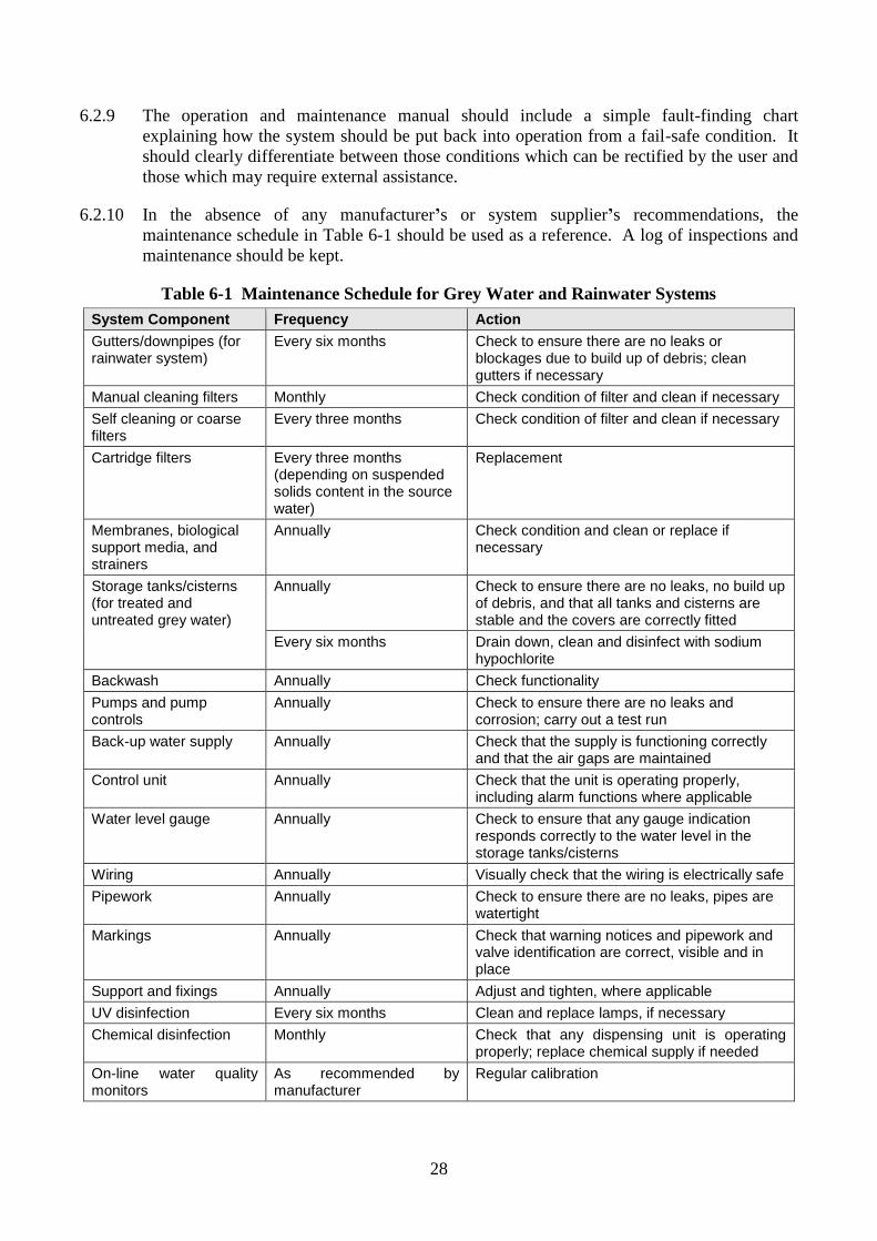
28
6.2.9 The operation and maintenance manual should include a simple fault-finding chart
explaining how the system should be put back into operation from a fail-safe condition. It
should clearly differentiate between those conditions which can be rectified by the user and
those which may require external assistance.
6.2.10 In the absence of any manufacturer’s or system supplier’s recommendations, the
maintenance schedule in Table 6-1 should be used as a reference. A log of inspections and
maintenance should be kept.
Table 6-1 Maintenance Schedule for Grey Water and Rainwater Systems
System Component Frequency Action
Gutters/downpipes (for rainwater system)
Every six months Check to ensure there are no leaks or blockages due to build up of debris; clean gutters if necessary
Manual cleaning filters Monthly Check condition of filter and clean if necessary
Self cleaning or coarse filters
Every three months Check condition of filter and clean if necessary
Cartridge filters Every three months (depending on suspended solids content in the source water)
Replacement
Membranes, biological support media, and strainers
Annually Check condition and clean or replace if necessary
Storage tanks/cisterns (for treated and untreated grey water)
Annually Check to ensure there are no leaks, no build up of debris, and that all tanks and cisterns are stable and the covers are correctly fitted
Every six months Drain down, clean and disinfect with sodium hypochlorite
Backwash Annually Check functionality
Pumps and pump controls
Annually Check to ensure there are no leaks and corrosion; carry out a test run
Back-up water supply Annually Check that the supply is functioning correctly and that the air gaps are maintained
Control unit Annually Check that the unit is operating properly, including alarm functions where applicable
Water level gauge Annually Check to ensure that any gauge indication responds correctly to the water level in the storage tanks/cisterns
Wiring Annually Visually check that the wiring is electrically safe
Pipework Annually Check to ensure there are no leaks, pipes are watertight
Markings Annually Check that warning notices and pipework and valve identification are correct, visible and in place
Support and fixings Annually Adjust and tighten, where applicable
UV disinfection Every six months Clean and replace lamps, if necessary
Chemical disinfection Monthly Check that any dispensing unit is operating properly; replace chemical supply if needed
On-line water quality monitors
As recommended by manufacturer
Regular calibration
29
6.3 Warranty and Guaranteed Service Life
6.3.1 All metal fittings, fasteners and components of the treatment system, other than pumps and
motors, shall be of non-corroding material and should have a service life of at least 15 years.
6.3.2 All mechanical and electrical parts installed within the treatment system should have a
minimum service life of 5 years and a minimum warranty period of 12 months.
6.3.3 The treatment system shall have a minimum warranty period of 3 years from the date of
delivery.
6.3.4 Providing the treatment system has been installed, used, and maintained in accordance with
the documentation supplied upon delivery, all labour and materials shall be supplied free of
charge by the system supplier or manufacturer during the warranty period for the purposes
of repairing any equipment or component failures. Servicing of the treatment system is the
responsibility of the owner; it is not provided free by the system supplier or manufacturer
and shall be conducted in accordance with the documentation supplied upon delivery.
6.4 Manuals
6.4.1 The following manuals and documents shall be provided:
(a) A comprehensive operations and maintenance manual, for use by service technicians,
which incorporates a detailed routine evaluation and maintenance schedule based on
appropriate and defined service intervals. The maintenance schedule shall specify the
work to be carried out by a service contractor as part of the continuous maintenance,
and any required work to be conducted by the owner of the system.
(b) A service report form which is suitable for use by service technicians.
(c) A user instruction manual which includes the following:
(i) Overview of the treatment system and intended use
(ii) Warranty and service life
(iii) Servicing requirements
(iv) Frequency of calibration of on-line water quality monitors
(v) Trouble shooting and signs of failures
(vi) A list of toxic substances / loads to be avoided
(vii) Desludging requirements (if any)
(viii) Safety information
(ix) Spreading of hydraulic loads
(x) Use of treated effluent – fit for purpose
(xi) Influent sources to be connected to the treatment system
(xii) Alarm information and use restrictions
(xiii) Manufacturers name and contact details
6.4.2 The instruction manual should include a simple fault-finding chart explaining how the
treatment system should be put back into operation from a fail-safe condition.
Differentiation should be clearly made between those conditions which can be rectified by
the user and those which may require external assistance by service technicians.
30
6.5 Submittals
6.5.1 The following information shall be provided by the manufacturers:
(a) Statement of warranty and service life containing the following:
(i) Equipment components under the warranty
(ii) Warranty terms, including service life period under the warranty
(iii) Warranty limitations
(iv) Warranty claims and procedures
(b) Installation manual and operation & maintenance manuals
(c) User instruction manual
(d) Service report form
(e) Certified engineering drawings, dimensioned and accompanied by a schedule of all
components with name, model, size, description, function, material of manufacture
and location in the treatment system. All components that are to be shown include the
following:
(i) Electric motor(s)
(ii) Gearbox
(iii) Compressor
(iv) Pump(s)
(v) Valves
(vi) Diffusers
(vii) Flow meter
(viii) Media
(ix) Media fixings
(x) Chlorinator
(xi) Pipework
(xii) Sludge collection and pumping equipment
(xiii) Baffles
(xiv) Partitions
(xv) Brackets
(xvi) Fastenings
(xvii) Electrodes
(xviii) Float switches
(xix) Control panel
(xx) Arrangement of the alarms
(f) Key plan showing location of treatment system within the development
(g) Plan and section showing location of the treatment system within the development and
surrounding facilities
(h) Process and instrumentation diagrams
(i) Hydraulic profile with supporting calculations
(j) Detailed process design calculations

31
(k) Detailed drawings with plan and elevation showing treatment plant room layout,
including pipework and equipment
(l) Route of access to the treatment plant room
(m) Ventilation and lighting details
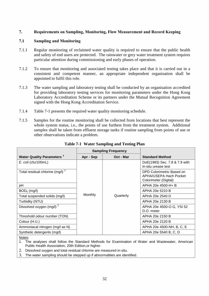
32
7. Requirements on Sampling, Monitoring, Flow Measurement and Record Keeping
7.1 Sampling and Monitoring
7.1.1 Regular monitoring of reclaimed water quality is required to ensure that the public health
and safety of end users are protected. The rainwater or grey water treatment system requires
particular attention during commissioning and early phases of operation.
7.1.2 To ensure that monitoring and associated testing takes place and that it is carried out in a
consistent and competent manner, an appropriate independent organisation shall be
appointed to fulfil this role.
7.1.3 The water sampling and laboratory testing shall be conducted by an organisation accredited
for providing laboratory testing services for monitoring parameters under the Hong Kong
Laboratory Accreditation Scheme or its partners under the Mutual Recognition Agreement
signed with the Hong Kong Accreditation Service.
7.1.4 Table 7-1 presents the required water quality monitoring schedule.
7.1.5 Samples for the routine monitoring shall be collected from locations that best represent the
whole system status, i.e., the points of use furthest from the treatment system. Additional
samples shall be taken from effluent storage tanks if routine sampling from points of use or
other observations indicate a problem.
Table 7-1 Water Sampling and Testing Plan
Water Quality Parameters 1
Sampling Frequency
Standard Method Apr - Sep Oct - Mar
E. coli (cfu/100mL)
Monthly
Quarterly
DoE(1983) Sec. 7.8 & 7.9 with
in-situ urease test
Total residual chlorine (mg/l) 2 DPD Colorimetric Based on
APHA/USEPA Hach Pocket
Colorimeter (Digital)
pH APHA 20e 4500-H+ B
BOD5 (mg/l) APHA 20e 5210 B
Total suspended solids (mg/l) APHA 20e 2540 D
Turbidity (NTU) APHA 20e 2130 B
Dissolved oxygen (mg/l) 2 APHA 20e 4500-O G, YSI 52
D.O. meter
Threshold odour number (TON) APHA 20e 2150 B
Colour (H.U.) APHA 20e 2120 B
Ammoniacal nitrogen (mg/l as N) APHA 20e 4500-NH, B, C, E
Synthetic detergents (mg/l) APHA 20e 5540 B, C, D
Notes:
1. The analyses shall follow the Standard Methods for Examination of Water and Wastewater, American Public Health Association, 20th Edition,or higher.
2. Dissolved oxygen and total residual chlorine are measured in-situ. 3. The water sampling should be stepped up if abnormalities are identified.
33
7.1.6 Should testing results of E. coli indicate a detected concentration of 1 to 10 cfu/100mL, re-
sampling and testing shall be performed immediately to confirm the results. System
operation shall also be investigated.
7.1.7 Should results of E. coli indicate a detected concentration of greater than 10 cfu/100mL, the
use of reclaimed water shall be suspended until the problem is resolved.
7.1.8 Should testing results of other water parameters exceed the water quality standards in Table
1-1, re-sampling and testing shall be performed immediately to confirm the results. System
operation shall also be investigated.
7.1.9 Should testing results of water parameters continue to exceed the water quality standards,
the following remedial measures shall be followed:
(a) Contact system supplier for recommendations and employ a qualified person to
resolve the problem.
(b) Suspend the use of reclaimed water. Back-up water supply shall be used instead.
(c) If the back-up water supply is potable water supply, the reclaimed water distribution
system shall be flushed and disinfected in accordance with WSD requirements prior to
using potable water supply to supplement the reclaimed water supply.
(d) The treatment system shall remain operational while conducting system operation
investigation. The treated effluent shall be diverted to the sewerage system.
(e) Once the problem is isolated and resolved, take samples from the system for testing E.
coli to confirm its compliance with the water quality standard before resuming usage
of reclaimed water.
(f) Should the problem persist, the reclaimed water system should be shutdown until the
problem is solved.
7.2 Flow Measurement
7.2.1 The total volume of all grey water collected shall be fully measured.
7.2.2 The total volume of all rainwater collected shall be fully measured.
7.2.3 The total volume of the reclaimed water treated and delivered to end users (e.g. treated grey
water and rainwater) shall be fully measured.
7.2.4 Flow measuring devices(s) shall be provided to measure the total quantity of all potable
mains water supply used as backup water supply.
7.2.5 Flow measuring devices(s) shall be provided to measure the total quantity of all grey water
and rainwater collected but not treated (i.e. overflowed or diverted to bypass and drainage
systems).
7.3 Record Keeping
7.3.1 The property manager shall maintain the records stated in Section 7.3.3 on site for a period
of five years using a standard daily record form (Sample found in Annex 2).
7.3.2 Records shall be readily available for WSD to check upon request.
34
7.3.3 Records to be maintained shall include the following:
(a) Water sampling and testing analyses
(b) Records of volume of grey water collected (daily)
(c) Records of volume of rainwater collected (daily, whenever rainwater is collected)
(d) Records of volume of reclaimed water treated (daily)
(e) Records of volume of potable mains water supply supplied as back-up water with
reason for its use (daily)
(f) Records of volume of grey water and rainwater collected but not treated, e.g.,
overflowed, bypassed or drained (daily)
(g) Records of volume of reclaimed water delivered to end users (daily)
(h) Operating hours (preferably daily records of on/off cycles combined with flows)
(i) Records from visual system inspection of reclaimed water system conducted annually
by licensed plumber
(j) Logs of inspections and maintenance work carried out by maintenance staff
(k) Records of chemical consumption
7.3.4 The property manager shall inform WSD if back-up potable water is used to supplement the
reclaimed water while there are surplus grey water and/or rainwater at the same time.
7.3.5 The property manager shall ensure that all system documentation, including installation
drawings, as-built records, amendment records, manuals, warranties, certificates and
maintenance records are passed on to future owners when the property is sold.
7.3.6 System suppliers and delegated maintenance companies shall maintain a database of
installed systems and inform property managers shall their contact details change. It is
recommended that a label describing the revised contact details be affixed to the control
cabinet at the next service visit.
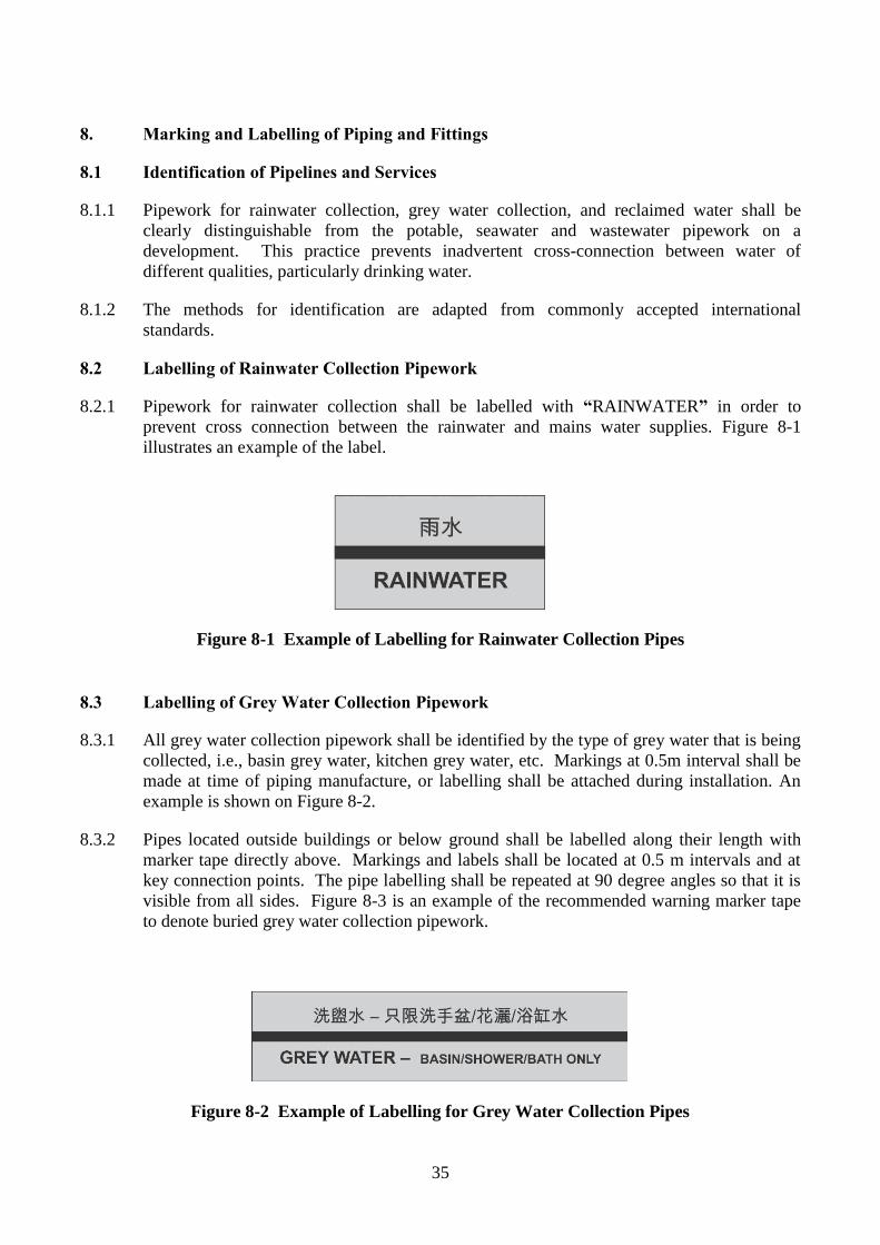
35
8. Marking and Labelling of Piping and Fittings
8.1 Identification of Pipelines and Services
8.1.1 Pipework for rainwater collection, grey water collection, and reclaimed water shall be
clearly distinguishable from the potable, seawater and wastewater pipework on a
development. This practice prevents inadvertent cross-connection between water of
different qualities, particularly drinking water.
8.1.2 The methods for identification are adapted from commonly accepted international
standards.
8.2 Labelling of Rainwater Collection Pipework
8.2.1 Pipework for rainwater collection shall be labelled with “RAINWATER” in order to
prevent cross connection between the rainwater and mains water supplies. Figure 8-1
illustrates an example of the label.
Figure 8-1 Example of Labelling for Rainwater Collection Pipes
8.3 Labelling of Grey Water Collection Pipework
8.3.1 All grey water collection pipework shall be identified by the type of grey water that is being
collected, i.e., basin grey water, kitchen grey water, etc. Markings at 0.5m interval shall be
made at time of piping manufacture, or labelling shall be attached during installation. An
example is shown on Figure 8-2.
8.3.2 Pipes located outside buildings or below ground shall be labelled along their length with
marker tape directly above. Markings and labels shall be located at 0.5 m intervals and at
key connection points. The pipe labelling shall be repeated at 90 degree angles so that it is
visible from all sides. Figure 8-3 is an example of the recommended warning marker tape
to denote buried grey water collection pipework.
Figure 8-2 Example of Labelling for Grey Water Collection Pipes
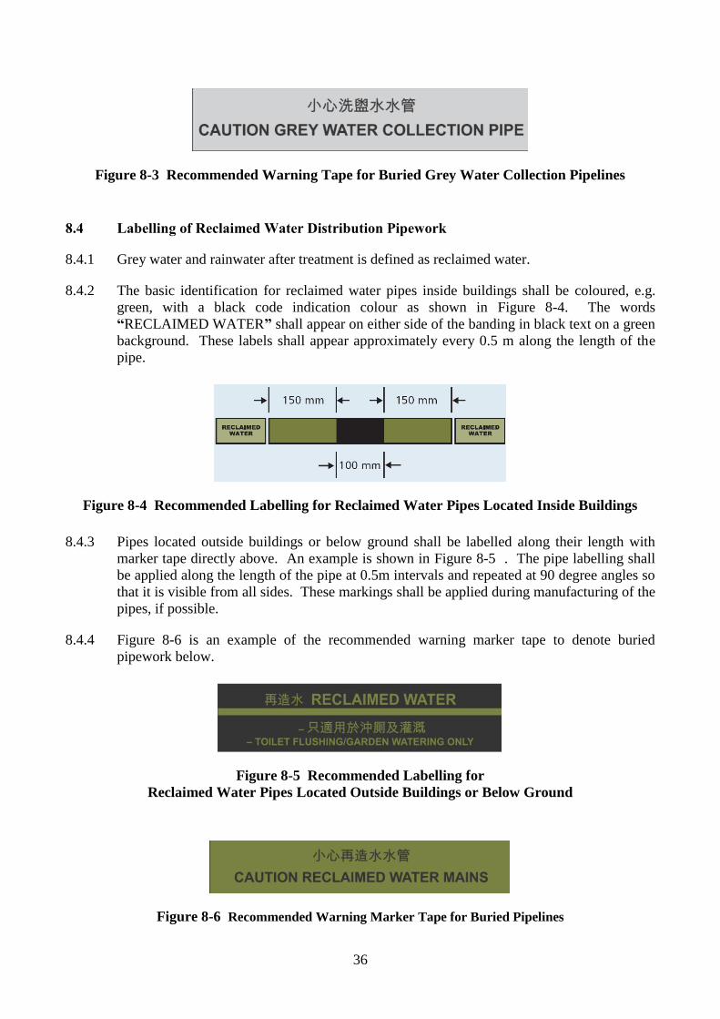
36
Figure 8-3 Recommended Warning Tape for Buried Grey Water Collection Pipelines
8.4 Labelling of Reclaimed Water Distribution Pipework
8.4.1 Grey water and rainwater after treatment is defined as reclaimed water.
8.4.2 The basic identification for reclaimed water pipes inside buildings shall be coloured, e.g.
green, with a black code indication colour as shown in Figure 8-4. The words
“RECLAIMED WATER” shall appear on either side of the banding in black text on a green
background. These labels shall appear approximately every 0.5 m along the length of the
pipe.
Figure 8-4 Recommended Labelling for Reclaimed Water Pipes Located Inside Buildings
8.4.3 Pipes located outside buildings or below ground shall be labelled along their length with
marker tape directly above. An example is shown in Figure 8-5 . The pipe labelling shall
be applied along the length of the pipe at 0.5m intervals and repeated at 90 degree angles so
that it is visible from all sides. These markings shall be applied during manufacturing of the
pipes, if possible.
8.4.4 Figure 8-6 is an example of the recommended warning marker tape to denote buried
pipework below.
Figure 8-5 Recommended Labelling for
Reclaimed Water Pipes Located Outside Buildings or Below Ground
Figure 8-6 Recommended Warning Marker Tape for Buried Pipelines
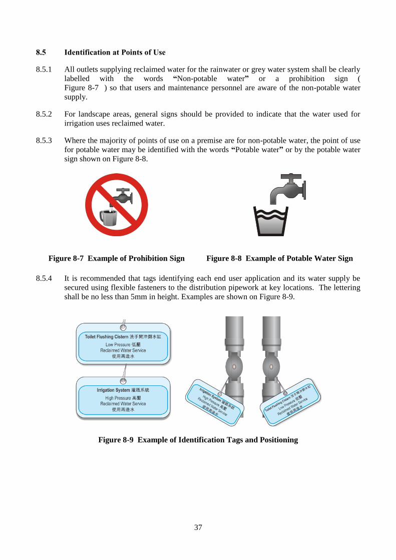
37
8.5 Identification at Points of Use
8.5.1 All outlets supplying reclaimed water for the rainwater or grey water system shall be clearly
labelled with the words “Non-potable water” or a prohibition sign (
Figure 8-7 ) so that users and maintenance personnel are aware of the non-potable water
supply.
8.5.2 For landscape areas, general signs should be provided to indicate that the water used for
irrigation uses reclaimed water.
8.5.3 Where the majority of points of use on a premise are for non-potable water, the point of use
for potable water may be identified with the words “Potable water” or by the potable water
sign shown on Figure 8-8.
Figure 8-7 Example of Prohibition Sign
Figure 8-8 Example of Potable Water Sign
8.5.4 It is recommended that tags identifying each end user application and its water supply be
secured using flexible fasteners to the distribution pipework at key locations. The lettering
shall be no less than 5mm in height. Examples are shown on Figure 8-9.
Figure 8-9 Example of Identification Tags and Positioning
38
9. Special Considerations for New Developments
9.1 General
9.1.1 Developments which contain facilities discharging clinical or chemical wastes shall not set
up grey water systems.
9.1.2 Examples of major producers are:
(a) Hospitals
(b) Government clinics
(c) Dental hospital
(d) Nursing homes (including dialysis centers)
(e) Maternity homes
9.1.3 Examples of small clinical waste producers are:
(a) Private medical clinics (including Chinese medicine practitioners)
(b) Dental clinics
(c) Medical laboratories
(d) Residential care homes including those for the elderly
(e) Universities with medical teaching or research
39
10. Safety Precautions
10.1 Safety Precautions for Operations/Maintenance Staff
10.1.1 Training in safe work procedure, including the use and maintenance of protective equipment
shall be provided to the personnel carrying out the grey water and rainwater system
commissioning.
10.1.2 Grey water and rainwater treatment may involve application of relatively aggressive and
toxic chemicals which is a major concern. All personnel involved shall be fully conversant
with the safe handling of the products.
10.1.3 Chemicals used for disinfection may be hazardous in undiluted form through contact,
ingestion or inhalation. Containers should be properly labelled and kept in a secure place
away from residents. Chemical suppliers must provide guidance on handling precautions
and response procedures in case of accidental contact or ingestion. Chemicals shall be
stored at an appropriate location to facilitate chemical handling. Chemicals shall be stored
in accordance to Fire Services Department’s requirements for bulk storage. Storage
quantities shall not exceed the exempted quantity under the Dangerous Goods Ordinance
(Cap. 295) and its subsidiary regulations.
10.1.4 Sodium hypochlorite solution is a poisonous substance classified as Category 4 dangerous
goods item. The solution should be stored in tanks fabricated from fibreglass or rubber
lined steel. Under the existing Dangerous Goods Regulations, storage of sodium
hypochlorite in quantities exceeding 250 litres requires a license.
10.1.5 Material safety data sheet (MSDS) and relevant recognized data sheet for chemicals used in
grey water and rainwater treatment processes shall be provided by the system supplier or
manufacturer and included in the operation and maintenance manual.
10.1.6 MSDS and relevant warning/safety label shall be provided on the surface of chemical
buckets. The MSDS and labels shall be properly protected against water and chemical
damage.
10.1.7 Eye wash bottles or washing basin with fresh water tap shall be provided adjacent to the
grey water and rainwater treatment chemicals tanks or any appropriate location for
emergency use. The water contained in the eye wash bottle shall be replaced periodically.
10.1.8 Mechanical or natural ventilation shall be provided to the room entirely or partially used for
chemical storage.
10.1.9 Electrical work must only be undertaken by a competent electrician. Unless specifically
designed to operate under submerged conditions, all electrical devices and connections
should be made above the maximum flood level of the system under fault conditions. An
electrical safety certificate should be issued upon completion of electrical installation or
maintenance work.
10.1.10 Electrical fittings and luminaries serving the chemical storage area shall be weather-proof
and corrosion resistant type.
10.1.11 Warning signs shall also be erected to restrict the unauthorised access to grey water and
rainwater treatment systems.
40
10.1.12 Any part of the grey water system should be assumed to be contaminated with pathogenic
bacteria. Plumbers, maintenance personnel and any others who come into contact with grey
water or reclaimed water should wash their hands before consuming food. Grey water
collection pipework and tanks should be handled as if contaminated with faecal material.
Gloves and overalls should be worn during routine cleaning and maintenance activities, and
when cutting into the system.
10.1.13 Sufficient personal protective equipment shall be provided to protect workers from exposure
to potential hazards such as aerosols.
10.2 Safety Precautions for End Users
10.2.1 End users shall always wash hands immediately after being in contact with reclaimed water.
If splashed in the eyes, wash immediately with clean water. Avoid any unnecessary contact
with reclaimed water.
10.2.2 End users shall not consume food or drink while working with reclaimed water. Wash hands
and face with fresh water before eating and finishing work.
10.2.3 End users shall cover any wounds, after washing with soap and fresh water, with a
waterproof dressing to prevent contact with reclaimed water.
10.2.4 All workers or persons likely to be using reclaimed water are required to have an orientation
to explain that reclaimed water is being used, that reclaimed water is not to be used for
drinking, handwashing or other similar uses, and that they shall wash their hands and face
with fresh water before eating or finishing work.
10.2.5 Legionella level is of concern where aerosols can be developed. If the water is to be used in
such a way that aerosols would be generated, the designers, workers and other end users
must take necessary precautions to prevent proliferation of this organism in the usage.
Refer to the latest version of Code of Practice for Prevention of Legionnaires’ Disease by
the Prevention of Legionnaires’ Disease Committee for recommendations.
10.3 Safety Precautions for Spray Irrigation Using Reclaimed Water
10.3.1 Suitable precautionary measures shall be applied to prevent the public from making direct
contact with reclaimed water from spray irrigation.
10.3.2 Spray irrigation, except for automatic ones, shall only be done during periods of low wind
velocity.
10.3.3 Spray irrigation, except for automatic ones, shall be stopped when wind is blowing toward
sensitive areas subject to aerosol drift or windblown spray.
10.3.4 Spray Irrigation shall be done at off-hours, when the public or employees would not be in
areas subject to aerosols or spray.
10.3.5 During spraying, the irrigation spot shall be fenced off to exclude the public from entering.
10.3.6 Spray irrigation shall be located away from air conditioners, fan intake points and areas
where food or drink is processed for consumption.
41
10.3.7 Signage of “Reclaimed Water – Do Not Drink”, or prohibition sign as shown in
Figure 8-7 shall be provided in appropriate locations.
10.4 Safety Precautions for Street Cleansing Using High Pressure Sprayer with Reclaimed
Water
10.4.1 Suitable precautionary measures shall be applied to prevent the public from making direct
contact with reclaimed water from street cleansing using high pressure sprayer.
10.4.2 Street cleansing using high pressure sprayer shall only be done during periods of low wind
velocity.
10.4.3 Street cleansing using high pressure sprayer shall be stopped when wind is blowing toward
sensitive areas subject to aerosol drift or windblown spray.
10.4.4 Street cleansing using high pressure sprayer shall be done at off-hours, when the public or
employees would not be in areas subject to aerosols or spray.
10.4.5 During street cleansing, the area shall be fenced off to exclude the public from entering.
10.4.6 High pressure spraying shall avoid areas near air conditioners, fan intake points and areas
where food or drink is processed for consumption.
42
11. Recommended Practice for Occupants of Developments with Grey Water Systems
11.1 General
11.1.1 Occupants of the development shall be educated not to pour excessive amounts of
disinfectants or other household cleaning agents into basins and sinks connected to the grey
water collection system.
11.1.2 The addition of grease, oil, and solid material to kitchen shall be kept to a minimum, by
disposing of these wastes as kitchen refuse rather than down the drain.
11.1.3 Avoid pouring waste cooking oil down a drain collecting grey water for reuse. They should
be disposed of at the cisterns instead.
11.1.4 Blackwater shall not be poured into basins and sinks connected to the grey water collection
system.
43
12. Recommended Education and Training on the Proper Use of Treated Grey Water and
Rainwater
12.1 General
12.1.1 Education and training shall be provided to staff and residents of developments using
treated grey water and/or rainwater.
12.1.2 Training for staff specifically involved with the operations and maintenance of the grey
water and/or rainwater treatment system shall be separately provided and incorporate safety
precautions for operations and maintenance staff as discussed in Section 10.1.
12.2 Recommended Education and Training Content for Residents
12.2.1 Education and training for residents shall incorporate the following:
(a) Overview of Hong Kong’s Total Water Management strategy, including the key
initiatives on water demand management and water supply management
(b) Overview of the treatment technology used within the development for treating grey
water and/or rainwater, including the sources of the grey water and/or rainwater
collected
(c) Prohibited uses as discussed in Section 1.2
(d) Safety precautions for end users as discussed in Section 10.2
(e) Proper practices within household as discussed in Section 11.1
12.2.2 Posters and pamphlets may be used to reinforce the education and training.
12.3 Recommended Education and Training Content for Staff
12.3.1 Education and training for staff within developments shall incorporate the following:
(a) Overview of Hong Kong’s Total Water Management strategy, including the key
initiatives on water demand management and water supply management
(b) Overview of the treatment technology used within the development for treating grey
water and/or rainwater, including the sources of the grey water and/or rainwater
collected
(c) Prohibited uses as discussed in Section 1.2
(d) Safety precautions for end users, irrigation, and street cleansing using high pressure
sprayer as discussed in Sections 10.2, 10.3 and 10.4, respectively
(e) Proper practices within household as discussed in Section 11.1
12.3.2 Posters and pamphlets may be used to reinforce the education and training.
44
13. Compliance with Water Pollution Control Ordinance and Regulations (Cap. 358) and
associated Environmental Ordinances & Regulations
13.1 General
13.1.1 The design, operation and maintenance of the grey water reuse and rainwater harvesting
systems shall comply with environmental ordinances and regulations, including but not
limited to the Water Pollution Control Ordinance and Regulations (Cap. 358) (WPCO),
Noise Control Ordinance (Cap. 400), Air Pollution Control Ordinance (Cap. 311), Waste
Disposal Ordinance (Cap. 354), Country Parks Ordinance (Cap. 208) and Waterworks
Ordinance (Cap. 102). Such compliance shall include but not limited to the attainment of
relevant discharge licenses, if applicable.
13.1.2 Any discharges from the grey water and rainwater treatment systems to sewers, storm drains
or other environmental waters are subject to licensing control under the WPCO. The
discharges are required to comply with the licence standard to be specified according to the
WPCO Technical Memorandum –“Standards for Effluents Discharged into Drainage and
Sewerage Systems, Inland and Coastal Waters”.
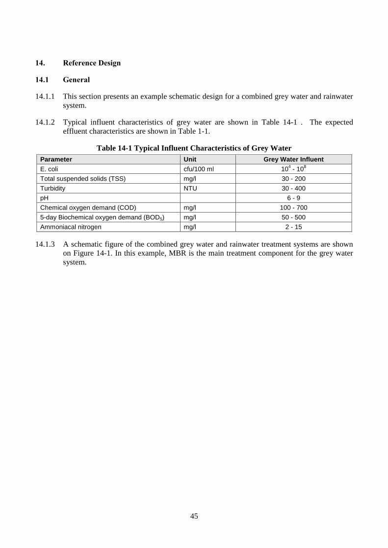
45
14. Reference Design
14.1 General
14.1.1 This section presents an example schematic design for a combined grey water and rainwater
system.
14.1.2 Typical influent characteristics of grey water are shown in Table 14-1 . The expected
effluent characteristics are shown in Table 1-1.
Table 14-1 Typical Influent Characteristics of Grey Water
Parameter Unit Grey Water Influent
E. coli cfu/100 ml 104 - 10
8
Total suspended solids (TSS) mg/l 30 - 200
Turbidity NTU 30 - 400
pH 6 - 9
Chemical oxygen demand (COD) mg/l 100 - 700
5-day Biochemical oxygen demand (BOD5) mg/l 50 - 500
Ammoniacal nitrogen mg/l 2 - 15
14.1.3 A schematic figure of the combined grey water and rainwater treatment systems are shown
on Figure 14-1. In this example, MBR is the main treatment component for the grey water
system.
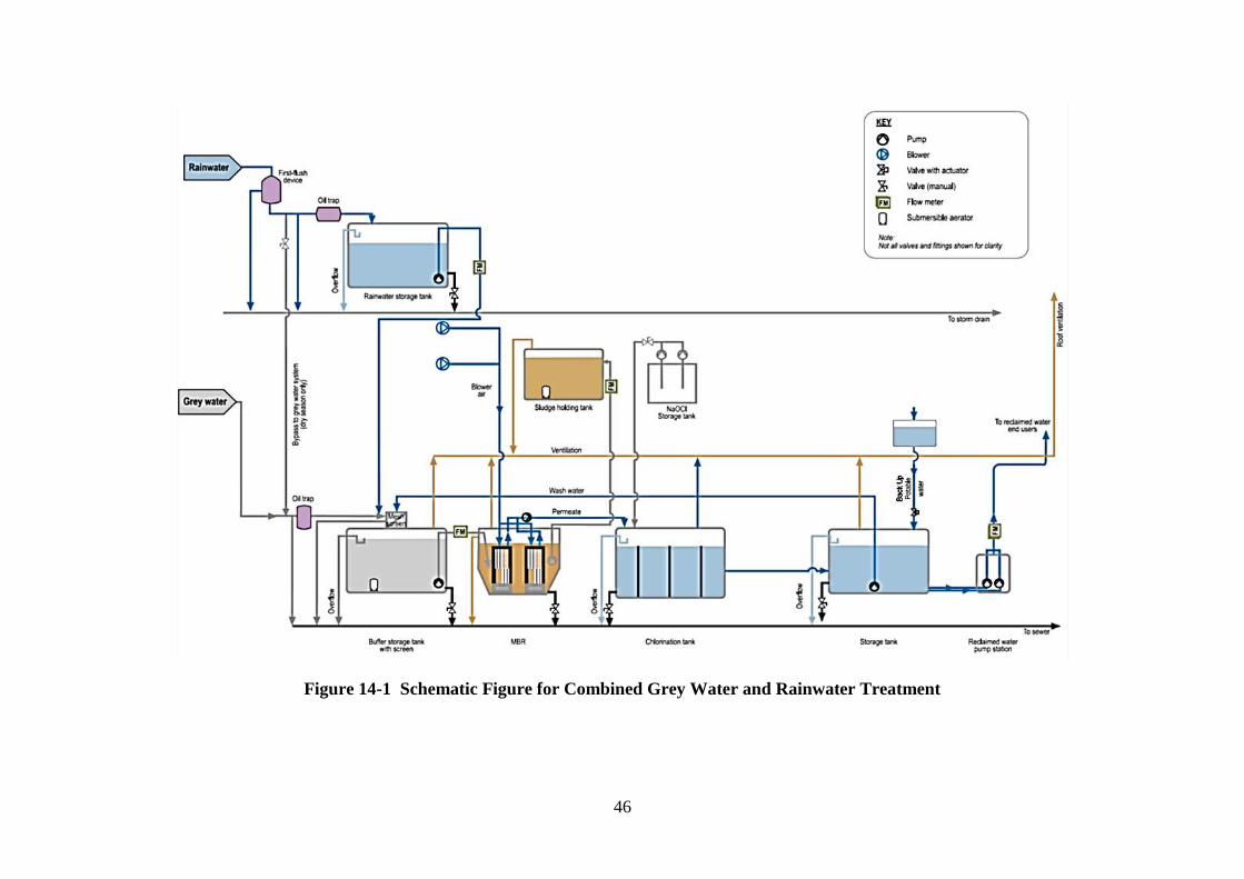
46
Figure 14-1 Schematic Figure for Combined Grey Water and Rainwater Treatment
47
GLOSSARY
Air Gap Physical break between the lowest level of the water inlet and the
maximum fault level or critical level of an appliance or
installation, a feed pipe, or an air inlet orifice incorporated into a
hydraulic circuit
Anti-Surcharge Valve Valve device installed directly in the pipework of a drainage
system intended to protect buildings from backflows and flooding
from drains or sewers
Backflow Movement of fluid from downstream to upstream within an
installation
Backflow Prevention Device Device which is intended to prevent contamination of potable
water by backflow in a water supply system
Back-Up Supply Supply of potable water from the public mains water supply or
other sources that can supplement the non-potable supply
Black Water Wastewater from toilets containing faeces and urine
Cistern Fixed container for storing water at atmospheric pressure for
subsequent reuse as part of a plumbing system
Cross Connection Physical hydraulic link or a removable link between two separate
systems which can lead to cross-contamination
Dead Leg Section of pipework through which no water flows, usually
created by closing a pipe after the removal of a terminal fitting
Domestic Use Use related to residential or similar dwellings
First-Flush Device Also known as a roof washer, a device that diverts the first few
minutes of rainfall away from a rainwater harvesting collection
system
Grey Water Water from sinks, baths, showers, and domestic appliances; in
these documents, also includes water from kitchen sinks,
dishwashers, laundry machines and air conditioners.
Non-Potable Water Any water other than potable water
Overflow Device that relieves the system of excess volume
Point of Use Point where water is drawn by the user either directly or by
connecting an apparatus
Potable Water Water suitable for human consumption
48
Public Mains Water Water supplied by a water undertaker, e.g. WSD
Rainwater Water arising from atmospheric precipitation
Reclaimed Water Water which has been treated so that its quality is suitable for
particular specified purposes, such as toilet flushing, irrigation,
external cleaning, etc.
Runoff Coefficient A multiplication factor used to establish the proportion of the
volume of rainwater that can be collected relative to the volume
that falls on the surface. It accounts for losses of rainwater due to
evaporation and absorption by the construction materials.
Spillover Level Level at which water starts to flow over a receiving vessel with all
outlets closed
49
REFERENCES
Code of Practice – Onsite Wastewater Management, Guidelines for Environmental Management,
EPA Victoria, 2008.
Draft 2010 California Plumbing Code.
Draft for Review, BS 8525 Grey Water Systems – Part 1, Code of Practice (WaterUK, 2009).
BS 8515: 2009 Rainwater Harvesting Systems – Code of Practice (BSi, UK).
Department of Communities and Local Government, UK, 2009. The Water Efficiency Calculator
for New Dwellings. The Government’s national calculation methodology for assessing water
efficiency in new dwellings in support of: The Code for Sustainable Homes, May 2009 and
subsequent versions; The Building Regulations 2000 (as amended). Downloaded from
www.planningportal.gov.uk.
Guidelines for the Design of Small Sewage Treatment Plants, EPD, 2006.
Guidelines for Water Reuse, US EPA, 2004.
Prevention of Legionnaires’ Disease, Code of Practice, EMSD, 2012 Edition.
Rainwater and Greywater Use in Buildings: Best Practice Guidance (C539) (CIRIA, UK, 2001).
Reclaimed Water, CIBSE Knowledge Series, 2005.
Water Reclamation Guidance – Design and Construction of Systems Using Grey Water (BSRIA,
UK, 2002).
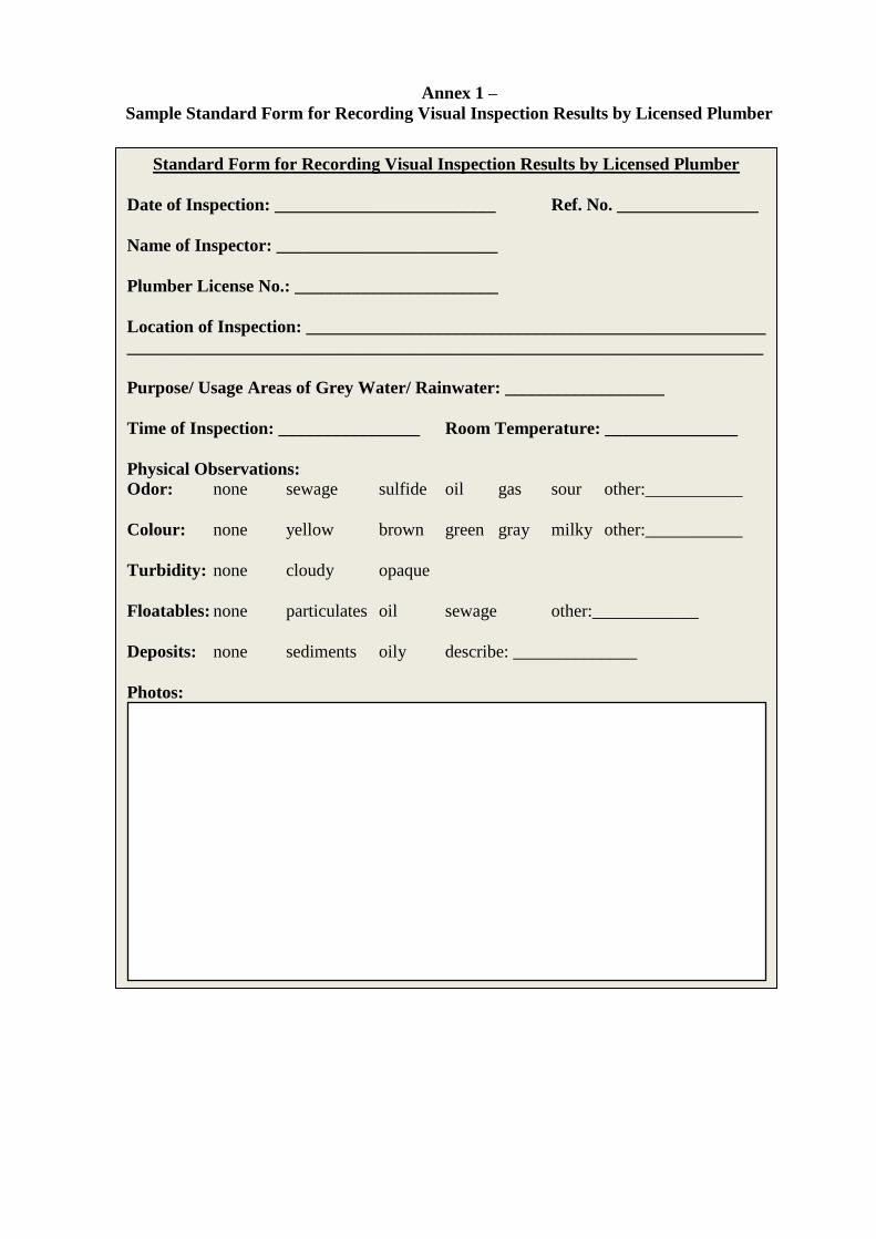
Annex 1 –
Sample Standard Form for Recording Visual Inspection Results by Licensed Plumber
Standard Form for Recording Visual Inspection Results by Licensed Plumber
Date of Inspection: _________________________ Ref. No. ________________
Name of Inspector: _________________________
Plumber License No.: _______________________
Location of Inspection: ____________________________________________________
________________________________________________________________________
Purpose/ Usage Areas of Grey Water/ Rainwater: __________________
Time of Inspection: ________________ Room Temperature: _______________
Physical Observations:
Odor: none sewage sulfide oil gas sour other:___________
Colour: none yellow brown green gray milky other:___________
Turbidity: none cloudy opaque
Floatables: none particulates oil sewage other:____________
Deposits: none sediments oily describe: ______________
Photos:
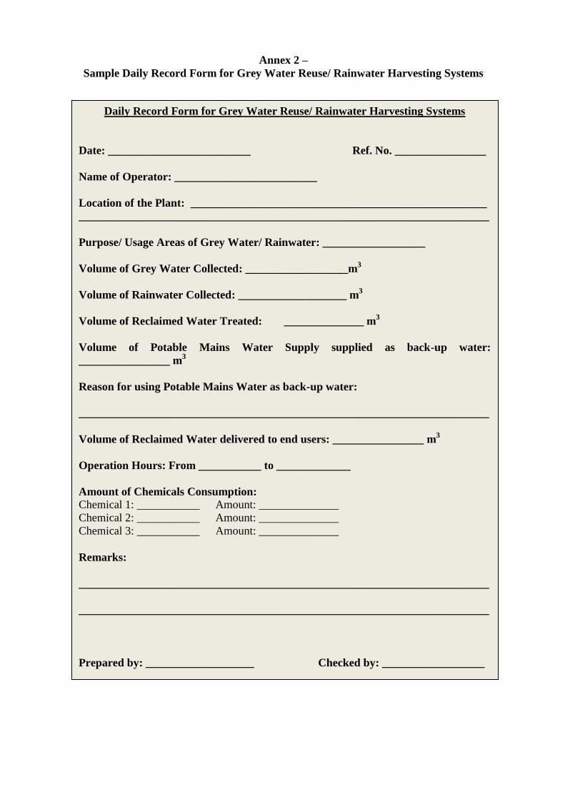
Annex 2 –
Sample Daily Record Form for Grey Water Reuse/ Rainwater Harvesting Systems
Daily Record Form for Grey Water Reuse/ Rainwater Harvesting Systems
Date: _________________________ Ref. No. ________________
Name of Operator: _________________________
Location of the Plant: ____________________________________________________
________________________________________________________________________
Purpose/ Usage Areas of Grey Water/ Rainwater: __________________
Volume of Grey Water Collected: __________________m3
Volume of Rainwater Collected: ___________________ m3
Volume of Reclaimed Water Treated: ______________ m3
Volume of Potable Mains Water Supply supplied as back-up water:
________________ m3
Reason for using Potable Mains Water as back-up water:
________________________________________________________________________
Volume of Reclaimed Water delivered to end users: ________________ m3
Operation Hours: From ___________ to _____________
Amount of Chemicals Consumption:
Chemical 1: ___________ Amount: ______________
Chemical 2: ___________ Amount: ______________
Chemical 3: ___________ Amount: ______________
Remarks:
________________________________________________________________________
________________________________________________________________________
Prepared by: ___________________ Checked by: __________________