technical specification all aluminium … specification all aluminium alloy conductor (aaac) 1....
TRANSCRIPT

TECHNICAL SPECIFICATION
ALL ALUMINIUM ALLOY CONDUCTOR (AAAC)
1. SCOPE
This specification covers design, Engineering, Manufacture, Testing, Inspection
before dispatch, forwarding, packing, transportation to sites, Insurance (both
during transit & storage ), storage, erection, supervision testing & commissioning
of all sizes of All Aluminum Alloy Conductors of the aluminum – magnesium-
silicon type for use in the distribution overhead power lines of NESCO of
Odisha.
The equipment offered shall have been successfully type testes and the design
shall have been satisfactory operation for a period not less than two years on the
date of bid opening. Compliance shall be demonstrated by submitting with the bid,
(i) authenticated copies of the type test reports and (ii) performance certificates
from the users.
The scope of supply includes the provision of type test, Rates of type tests shall be
given in the appropriate price schedule of the bidding document and will be
considered for evaluation. The Purchaser reserves the right to waive type tests as
indicated in the section on Quality Assurance, Inspection and Testing in the
specification.
The Aluminum Alloy Conductor shall conform in all respects to highest standards
of engineering, design, workmanship, this specification and the latest revisions of
relevant standards at the time of offer and the Purchaser shall have the power to
reject any work or materials, which, in his judgment, is not in full accordance
therewith.
STANDARDS
Except where modified by the specification, the Aluminum Alloy Conductor shall
be designed, manufactured and tested in accordance with latest editions of the
following standards.
IEC/ISO/ Other
International
Standard
IS Subject
…………………………………………………………………………………………
IEC :1089 Round wire concentric lay overhead electrical standard
conductors
IS 398 Aluminum Alloy Stranded Conductors
IS 9997 Aluminum Alloy redraw rods for electrical purposes
IEC 502 : 1994 Extruded solid dielectric insulated power cables for
rated voltages 1.0 KV up to 30 KV

IEC 104 Aluminum Magnesium Silicon alloy wire for overhead
IS 1778
line conductors Reels and drums of bare conductor.
BS : 6485-1971
PVC covered conductors for overhead power lines.
This list is not to be considered exhaustive and reference to a particular standard or
recommendation in this specification does not relieve the contractor of the
necessity of providing the goods complying with other relevant standards or
recommendations.
3. GENERAL
The wires shall be of heat treated aluminum, magnesium silicon alloy containing
approximately silcon-0.5 to 0.9 %. magnesium-0.6 % to 0.9%,Fe-0.5%
(maximum) , Copper- 0.1% (max ), mn- 0.03% , Cr-0.03%, Zn-0.1%, B-0.06%,
and having the mechanical and electrical properties specified in the table and be
smooth and free from all imperfections, such as, spills, splits and scratches.
Neutral grease shall be applied between the layers of wires. The drop point
temperature of the grease shall not be less than 1200
C.
3.1 Mechanical and Electrical Characteristics of Aluminium Alloy Wires used in
the Construction of Stranded Aluminium Alloy Conductors
Nominal
Diameter
Minimum
Diameter
Max.
Diam
eter
Cross
Sectional
Area
Mass
Minimum Breaking
Load Maximum
Resistance at
200C Before
stranding
After
stranding
1 2 3 4 5 6 7 8
mm mm mm mm2 Kg/km KN KN ohms/ km
3.15 3.12 3.18 7.793 21.04 2.37 2.29 4.290
3.81 3.77 3.85 11.40 30.78 3.52 3.34 2.938
4.26 4.22 4.30 14.25 38.48 4.40 4.18 2.345
Maximum resistance values given in column 8 have been calculated from the maximum values of the
resistively as specified and the cross sectional area based on the minimum diameter.
The minimum breaking load is calculated on nominal diameter at ultimate tensile strength of 0.309
KN / mm2
for wire before stranding and 95% of the ultimate tensile strength after stranding.
4. PHYSICAL CONSTANTS FOR ALUMINIUM ALLOY WIRES
4.1 Resistively :
For the purpose of this specification, the standard value of resistively of aluminum
alloy wire which shall be used for calculation is to be taken as 0.0325 ohm mm2
/m
at 200
C. the maximum value of resistively of any single wire shall not , however,

exceed 0.0328 ohm. mm2/m at 20
0 C
4.2 Density :
At a temperature of 200
C, the density of aluminum alloy wire is to be taken as
2700 kg/m3.
4.3 Temperature Coefficient of Linear Expansion :
The temperature coefficient of linear expansion of aluminium alloy wire is to be
taken as 23 x 10 –6
/ 0
C
4.4 Constant – Mass Temperature Coefficient
At a Temperature of 200
C, the constant – mass temperature coefficient of resistance of aluminum alloy wires, measured between two potential points
rigidly fixed to the wire, is taken as 0.00360/0
C
5. STANDARD SIZES
5.1 Nominal Sizes of Wires
The aluminum alloy wires for standard constructions covered by this specification
shall have the diameters as specified in the table and a tolerance of ±1% shall be
permitted on the nominal diameter.
5.2 Standard Conductors
The sizes, resistance and masses (excluding the mass of grease ) of stranded
aluminum alloy conductors shall be as given in table.
5.3 Mechanical and Electrical Characteristics of Aluminum Alloy Stranded
Conductors
Sl.
No.
Actual
Area
Stranding
and Wire Dia
Approx.
Overall Dia
Approx.
Mass
Calculated Maximum Resistance
at 200
C
Approx
Calculated Breaking
Load
1 2 3 4 5 6 7
mm2 mm mm kg/km ohms/km KN
1 55 7/3.15 9.45 149.20 0.621 16.044
2 100 7/4.26 12.78 272.86 0.339 29.344
5.3.1 Increase in Length due to Stranding
When straightened out, each wire in any particular layer of a stranded conductor,
except the central wire, is longer than the stranded conductor by an amount
depending on the lay ratio of that layer.

5.3.2 Resistance and Mass of Conductor
The resistance of any length of stranded conductor is the resistance of the same
length of any one wire multiplied by a constant as set out in the table below.
The mass of each wire in any particular layer of the stranded conductor, except
the central wire, will be greater than that of an equal length of straight wire by an
amount depending on the lay ratio of that layer. The total mass of any length of
an aluminum stranded conductor is, therefore, obtained by multiplying the mass
of an equal length of straight wire by an appropriate constant as mentioned
below. In calculating the stranding constants as mentioned in the table below,
the mean lay ratio, that is the arithmetic mean of the relevant minimum and
maximum values in table for lay ratio has been assumed for each layer.
5.3.3 Calculated Breaking Load of Conductor
For a conductor containing not more than 37 wires, 95% of the sum of
strength of the individual wires calculated from the values of the minimum
breaking load given in this specification.
For a conductor containing more than 37 wires, 90% of the sum of the
strengths of the individual wire calculated from the values of the minimum
breaking load given in this specification.
5.3.4 Calculated Area and Maximum Resistance of Conductor
The actual area of a stranded conductor has been taken as the sum of the cross-
sectional areas of the individual wires of nominal diameter.
Maximum resistance values of stranded conductor have been calculated on the
basis of maximum resistivity and the cross-sectional area based on the minimum
diameter of wires.
5.4 Stranding Constants
Number of Wires in
Conductor
Stranding Constants
Mass Electrical Resistance
(1) (2) (3)
7 7.091 0.1447
19 19.34 0.05357

6. JOINTS IN WIRES
6.1 Conductor containing seven wires
There shall be no joint in any wire of a stranded conductor containing seven
wires, except those made in the base rod or wire before final drawing.
6.2 Conductors containing more than seven wires
In stranded conductors containing more than seven wires, joints in individual
wires are permitted in any layer except the outermost layer ( in addit ion to those
made in the base rod or wire before final drawing ) but no two such joints shall
be less than 15 m apart in the complete stranded conductor. Such joints shall be
made by cold pressure butt welding. They are not required to fulfill the
mechanical requirements for unjointed wires.
7. STRANDING
The wire used in the construction of a stranded conductor shall, before and after
stranding, satisfy all the relevant requirements of this standard.
The lay ratio of the different layers shall be within the limits given in the table
for lay ratio.
In all constructions, the successive layers shall have opposite directions of lay,
the outermost layer being righ-handed. The wires in each layer shall be evenly
and closely stranded.
In aluminum alloy stranded conductors having multiple layers of wires, the lay
ratio of any layer shall not be greater than the lay ratio of the layer immediately
beneath it.
7.1
Lay Ratios for Aluminum Alloy Stranded Conductors
Number of Wires
in Conductor
LAY RATIOS
3/6 Wire Layer 12 Wire Layer 18 Wire Layer 24 Wire Layer
Min Max Min Max Min Max Min Max
7 10 14 --- --- --- --- --- ---
19 10 16 10 14 --- --- --- ---
NOTE: For the purpose of calculation the mean lay ratio shall be taken as the arithmetic mean of the
relevant minimum and maximum values given in this table

8. LENGTHS AND VARIATIONS IN LENGTHS :
Unless otherwise agreed between the Employer and the Contractor, stranded
aluminum alloy conductors shall be supplied in the manufacturer’s usual
production lengths to be indicated in the bid Schedule. The Employer reserves the
right to specify particular lengths of conductor such that certain drum lengths will
be shorter than others. There will in both cases be a permitted variation of –0 +
5% in the length of any one conductor length.
9. TESTS
9.1 Type Tests
The following tests shall be carried out as per relevant ISS once on samples of completed line conductor during each production run of up to 500 kms of the
conductor from each manufacturing facility.
9.1.1 Ultimate Tensile Strength Test
This test is intended to confirm not only the breaking strength of the finished
conductor but also that the conductor has been uniformly stranded.
A conductor sample of minimum 5 m length fitted with compression dead end clamps at
either end shall be mounted in a suitable tensile test machine. Circles perpendicular to
the axis of the conductor shall be marked at two places on its surface. Tension on the
conductor sample shall be increased at a steady rate upto 50% of the minimum UTS
specified and held for one minute. The circles drawn shall not be distorted due to
relative movement of the individual strands. Thereafter the load shall be increased at a
steady rate to the specified minimum UTS and held at that load for one minute. The
conductor sample shall not fail during this period. The applied load shall then be
increased until the failing load is reached and the value recorded.
9.1.2 D.C Resistance Test
On a conductor sample of minimum 5 m length two contact clamps shall be fitted with a pre-determined bolt torque. The resistance between the clamps shall be measured using a Kelvin double bridge by initially placing the clamps at zero separation and subsequently one meter apart. The test shall be repeated at least five times and the average value recorded. The value obtained shall be corrected
to the value at 200
C, which shall conform to the requirements of this specification.
9.2 Routine Tests
Measurement of Physical Dimensions : The samples should meet the desired

dimensional requirements before conducting following Routine Tests as per
relevant ISS.
9.2.1 Selection of Test Samples
Samples for the tests specified in this specification shall be taken by the
manufacturer before stranding, from not less than 10% of the individual lengths
of aluminium alloy wire included in any one final heat-treatment batch and
which will be included in any one consignment of the stranded conductors to be
supplied.
Alternatively, if desired by NESCO at the time of placing an order, that the tests
be made in the presence of his representative, samples of wire shall be taken
from length of stranded conductor.
Samples shall then be obtained by cutting 1.2 meters from the outer end of t he
finished conductor from not more than 10% of the finished reels or drums.
Tests for electrical and mechanical properties of aluminum alloy wire shall
ordinarily be made before stranding since wires unlaid from conductors may
have different physical properties from those of the wire prior to stranding
because of the deformation brought about by stranding and by straightening for
test.
Spools offered for inspection shall be divided into equal lots, the number of lots
being equal to the number of samples to be selected, a fraction of a lot being
counted as s complete lot. One sample spool shall be selected at random from
each lot.
The following test shall be carried out once on samples of completed line
conductor during each production run of up to 500 kms of the conductor from
each manufacturing facility.
9.2.2 Breaking Load Test
The breaking load of one specimen, cut from each of the samples taken shall be
determined by means of a suitable tensile testing machine. The load shall be
applied gradually and the rate of separation of the jaws of the testing machine
shall be not less than 25 mm / min and not greater than 100mm /min.
9.2.3 Elongation Test
The elongation of one specimen cut from each of the samples taken shall be
determined as follows:
The specimen shall be straightened by hand and an original gauge length of 200
mm shall be marked on the wire. A tensile load shall be applied as described
above and the elongation shall be measured after the fractured ends have been
fitted together. If the fracture occurs outside the gauge marks, or within 25 mm
of eithermark, and the required elongation is not obtained, the test shall be
disregarded and another test should be made.
When tested before and after stranding, the elongation shall not be less than 4% on a
gauge length of 200 mm.
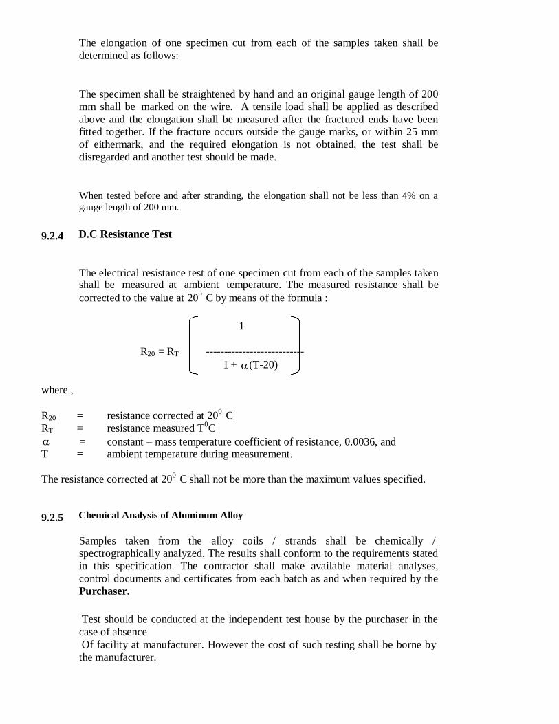
9.2.4 D.C Resistance Test
The electrical resistance test of one specimen cut from each of the samples taken shall be measured at ambient temperature. The measured resistance shall be
corrected to the value at 200
C by means of the formula :
1
R20 = RT ---------------------------
1 + (T-20)
where ,
R20 = resistance corrected at 20
0 C
RT = resistance measured T0C
= constant – mass temperature coefficient of resistance, 0.0036, and
T = ambient temperature during measurement.
The resistance corrected at 200
C shall not be more than the maximum values specified.
9.2.5 Chemical Analysis of Aluminum Alloy
Samples taken from the alloy coils / strands shall be chemically /
spectrographically analyzed. The results shall conform to the requirements stated
in this specification. The contractor shall make available material analyses,
control documents and certificates from each batch as and when required by the
Purchaser.
Test should be conducted at the independent test house by the purchaser in the
case of absence
Of facility at manufacturer. However the cost of such testing shall be borne by
the manufacturer.

9.2.6 Dimensional and Lay Length Check
The individual strands of the conductors shall be dimensionally checked
and the lay lengths checked to ensure that they conform to the requirements of this specification.
Ten percent drums from each lot shall be rewound in the presence
of the Purchaser or his representative to allow visual checking of the
conductor for joints, scratches or other surface imperfections and to
ensure that the conductor generally conforms to the requirements
this specification. The length of conductor wound on the drum shall
be re-measured by means of an approved counter / meter during the
rewinding process.
9.2.7 Visual and dimensional Checks on the Conductor Drums.
The drums shall be visually and dimensionally checked to ensure
that they conform to the requirements of this specification and of IS
1778: Specification for reels and drums of bare conductors. For
wooden drums, a suitable barrel batten strength test procedure is
required. The Bidder shall state in his bid the tests to be carried out on
the drums and shall include those tests in the Quality Assurance
Programme.
9.2.8 Acceptance Tests :
All tests required to confirm enclosed Guaranteed Technical Particulars
(GTP)
requirements of this specification needs to be conducted as
Acceptance Tests.
9 . 3 Test Reports.
a) Copies of type test reports shall be furnished in at least six copies along with
one original. One copy will be returned duly certified by the Owner only after
which the commercial production of the material shall start.
b) Record of routine test reports shall be maintained by the Supplier at his works
for periodic inspection by the Owner’s representative.
c) Test certificate of tests during manufacture shall be maintained by the Contractor. These shall be produced for verification as and when desired by the
Owner.
10. Packing.
a) The conductor shall be supplied in returnable, strong, wooden drums provided

with lagging of adequate strength, constructed to protect the conductor
against any damage and displacement during transit, storage and subsequent
handling and stringing operations in the field. The Contractor shall be responsible for any loss or damage during transportation handling and storage due to
improper packing. The drums shall generally conform to IS: 1778-1980,
except as otherwise specified hereinafter.
b) The drums shall be suitable for wheel mounting and for letting off the
conductor under a minimum controlled tension of the order of 5 KN.
c) The Contractor should submit their proposed drum drawings along with the bid.
d) The Contractor may offer more than one length of the conductor in a single drum.
e) All wooden components shall be manufactured out of seasoned soft wood free
from defects that may materially weaken the component parts of the drums.
Preservative treatment shall be applied to the entire drum with preservatives of a quality, which is not harmful to the conductor.
f) The flanges shall be of two ply construction with a total thickness of 64 mm
with each ply at right angles to the adjacent ply and nailed together. The nails
shall be driven from the inside face flange, punched and then clenched on the
outer face. Flange boards shall not be less than the nominal thickness by
more than 2mm. There shall not be less than 2 nails per board in each circle. Where a slot is cut in the flange to receive the inner end of the conductor the
entrance shall be in line with the periphery of the barrel.
g) The wooden battens used for making the barrel of the conductor shall be of
segmental type. These shall be nailed to the barrel supports with at least two nails. The batten shall be closely butted and shall provide a round barrel with
smooth external surface. The edges of the battens shall be rounded or
chamfered to avoid damage to the conductor.
h) Barrel studs shall be used for the construction of drums. The flanges shall be
holed and the barrel supports slotted to receive them. The barrel studs shall be treaded over a length on either end, sufficient to accommodate washers, spindle
plates and nuts for fixing flanges at the required spacing.
i) Normally, the nuts on the studs shall stand protruded of the flanges. All the
nails used on the inner surface of the flanges and the drum barrel shall be
counter sunk. The ends of barrel shall generally be flushed with the top of the nuts. j) The inner cheek of the flanges and drum barrel surface shall be painted with bitumen
based paint.
k) Before reeling, card board or double corrugated or thick bituminous water proof bamboo paper shall be secured to the drum barrel and inside of flanges of
the drum by means of a suitable commercial adhesive material. The paper
should be dried before use. After reeling the conductor, the exposed surface of the outer layer of conductor shall be wrapped with water proof thick
bituminous bamboo paper to preserve the conductor from dirt, grit and damage
during transport and handling.
l) A minimum space of 75 mm for conductor shall be provided between the
inner surface of the external protective lagging and outer layer of the conductor. Outside the protective lagging, there shall be minimum of two binders
consisting of hoop iron/galvanized steel wire. Each protective lagging shall
have tow recesses to accommodate the binders.
m) Each batten shall be securely nailed across grains as far as possible to the
flange, edges with at least 2 nails per end. The length of the nails shall not be
less than twice the thickness of the battens. The nails shall not protrude above the general surface and shall not have exposes sharp, edges or allow the battens
to be released due to corrosion.

n) The nuts on the barrel studs shall be tack welded on the one side in order to fully secure them. On the second end, a spring washer shall be used.
o) A steel collar shall be sued to secure all barrel studs. This collar shall be
located between the washers and the steal drum and secured to the central
steel plate by welding. p) Outside the protective lagging, there shall be minimum of two binders consisting of
hoop iron/ galvanized steel wire. Each protective lagging shall have two recesses to
accommodate the binders.
q) The conductor ends shall be property sealed and secured with the help of U-nail on the side of one of the flanges to avoid loosening of the conductor layers
during transit and handling.
r) As an alternative to wooden drum Contractor may also supply the conductors in
non- returnable painted steel drums. After preparation of steel surface according
to IS:
9954, synthetic enamel paint shall be applied after application of one coat of
primer. Wooden/Steel drum will be treated at par for evaluation purpose and accordingly the Contractor should quote in the package.
11.0 Marking.
Each drum shall have the following information stenciled on it in indelible ink along with
other essential data:
(a) Contract/Award letter number
(b) Name and address of consignee.
(c) Manufacture’s name and address.
(d) Drum and lot number
(e) Size and type of conductor
(f) Length of conductor in meters
(g) Arrow marking for unwinding
(h) Position of the conductor ends
(i) Number of turns in the outer most layer.
(j) Gross weight of the drum after putting lagging.
(k) Average weight of the drum without lagging.
(l) Net weight of the conductor in the drum
(m) Month and year of manufacture of conductor
The above should be indicated in the packing list also.
12.0 Verification Conductor Length

The Owner reserves the right to verify the length of conductor after unreeling at least five
(5) percent of the drums in a lot offered for inspection. For the balance drums, length verification shall be done by the owner based on report/certification from Manufacturer/ Contractor.
13. REJECTION AND RETESTS
13.1 Type Tests
Should the conductor fail any of the type tests specified above, the
Purchaser will not accept any conductor manufactured from the
material, nor conductor made by the manufacturing methods used for the
conductor which failed the test.
The manufacturer shall propose suitable modifications to his
materials and techniques in order that he can produce conductor which will satisfactorily pass the type test requirements.
13.2 Routine Tests
Should any one of the test pieces first selected fail the requirements of
the tests, two further samples from the same batch shall be selected for
testings, one of which shall be from the length from which the original
test sample was taken
unless that length has been withdrawn by the
manufacturer.
Should the test pieces from both these additional samples
satisfy the requirements of the tests, the batch represented by these
samples shall be deemed to comply with the standard. Should the test
pieces from either of the two additional samples fail, the batch
represented shall be deemed not to comply with the standard.
If checks on individual strand diameters, conductor lay lengths and
conductor surface condition indicate non-compliance with the
requirements of the specification, the particular drum will be rejected.
Inspection will then be carried out on two further drums within the same
batch. If the conductor on either of the drums is non-complaint, the
complete batch will be rejected.

GURANTEED TECHNICAL PARTICULARS
FOR ALL ALUMINIUM ALLOY CONDUCTOR
Sl.
No.
Perticulars
Specified
Requirement
Details
furnished by
the bidder
size wise
1. Nominal Aluminium Alloy area of
conductor in Sq.mm : 55 100
2. No. of stands : 7 7
3.
Wire dia. in mm
a) Nominal : 3.15 4.26
b) Minimum : 3.12 4.22
c) Maximum : 3.18 4.3
4. Approximate Over all diameter of
conductor in mm : 9.45 12.78
5.
Cross sectional area in Sq.mm
i) Individual wire : 7.793 14.25
ii) Standard Conductor : 55 99.81
6.
Minimum breaking load in KN
i) Individual wire : 2.29 4.18
ii) Standard Conductor
(U.T.S) : 16.03 29.26
7.
Approximate mass in Kg. Per KM of
Aluminium Alloy conductor
i) Individual wire : 21.04 38.48
ii) Standard Conductor : 149.20 272.86
8. Calculated maximum DC resistance at
200C in Ohm/Km
i) Individual wire : 4.290 2.345
ii) Standard Conductor : 0.621 0.339
13. Modulus of Elasticity of Aluminium
Alloy conductor Kg/Sq.mm : 0.6324X10
6
16.
Co-efficient of linear expansion per
degree centigrade for
a) Individual /0C
b) Standard conductor/0C
:
:
23X106

23X106
17. Standard length (Mtr.)
: 2000 +5%
18. Lay ratio for 7 wire conductor : Min Max
10 14
19. Direction of Lay : Right hand
20.
Standard according to which the
conductor will be manufactured and
tested
: IS : 398 (Part-4) – 1994
21. Size of the drum in mm (as per IS-
1778/80 with Amendment I /1989 :
To be offered by the
Bidder
To be offered by the
Bidder
22. Length of conductor in each drum in
Km :
To be offered by the
Bidder
To be offered by the
Bidder