is 1948 (1961): specification for aluminium doors, windows
TRANSCRIPT

Disclosure to Promote the Right To Information
Whereas the Parliament of India has set out to provide a practical regime of right to information for citizens to secure access to information under the control of public authorities, in order to promote transparency and accountability in the working of every public authority, and whereas the attached publication of the Bureau of Indian Standards is of particular interest to the public, particularly disadvantaged communities and those engaged in the pursuit of education and knowledge, the attached public safety standard is made available to promote the timely dissemination of this information in an accurate manner to the public.
इंटरनेट मानक
“!ान $ एक न' भारत का +नम-ण”Satyanarayan Gangaram Pitroda
“Invent a New India Using Knowledge”
“प0रा1 को छोड न' 5 तरफ”Jawaharlal Nehru
“Step Out From the Old to the New”
“जान1 का अ+धकार, जी1 का अ+धकार”Mazdoor Kisan Shakti Sangathan
“The Right to Information, The Right to Live”
“!ान एक ऐसा खजाना > जो कभी च0राया नहB जा सकता है”Bhartṛhari—Nītiśatakam
“Knowledge is such a treasure which cannot be stolen”
“Invent a New India Using Knowledge”
है”ह”ह
IS 1948 (1961): Specification for aluminium doors, windowsand ventilators [CED 11: Doors, Windows and Shutter]


Indian Standard
IS : 1948 -1961(Reaffirmed 2001)
REAFFIRMED 2006
Gr 8
SPECIFICATION FOR ALUMINIUM DOORS,WINDOWS AND VENTILATORS
Tenth Reprint MARCH 2006(Incorporating Amendment No. I)
UDC 69.028 : 691.771
. Copyright 1973
BUR E A U OF I N D I A N S TAN DAR D SMANAK BHAVAN. 9 BAHADUR SHAH ZAFAR MARG
NEW DELHI 110002
April 1962

IS: 1948 - 1961
Indian StandardSPECIFICATION FOR ALUMINIUM DOORS,
WINDOWS AND VENTILATORS
Doors, Windows and Building Furniture Sectional Committee, BDC 11
eAa;""a..SHRI D. P. ASAR
J\/,,,,b,,.,SHRI s. H. ABHYANKARSHRI AXSHOY BosESHRI AIIIYA MADHOB CHAKI
SH •• R. I{. CHARISHRI K. SRunVAS (AII,,,,,ate)
SHRI M. C. GANDHISHR. K. R. ANANTHASWAIIY (Alte,."tJI,)ENGINEER INCH.\RGE, \VOOD WORKS
DEPAaTMENT (AIIWJlate)SHRI K. If. GUPTASHRI M. J. JALSHRI S. K. JOGLEKAR
SHR. V. M. PUNDLIK (AII,,.lta',)SHRI L. S. LuI-LA
SHRI J. N. MULLAN (AlIt',.,,")SHRI C. P. MAl-lit
SHRI SHRI I{RISHNA (Alte,,"ale)CAPT x, J. MASANISSRI R. P. MIIATRESHRI S. I{. MULLICKREPRESENTATIVE
SHRI J. D. SHASTRISHRI C. D. SHARMA (Alte,."ate)
SHRI N. B. SH.O....
SHRI H. THOMSONSHRI G. W. M. WHITTLE (AlI,,.,,.'e)
DR H. C. VISVESVARAYA,Deputy Director (Bldg)
Re/>rlsetJli,.,Sunderdas "Co, Bombay
Central Public Work. DepartmentBallardie Thompson It Matthew. Ltd, CalcuttaCalcutta Cabinet Maken' ct Furnishers' Association,
CalcuttaIndian Aluminium Co Ltd, Calcutta
)lan Industrial Corporation Ltd, Jaipuf
Hind Construction Co Ltd. CalcuttaGodrej 4: Boyce Manufacturing Co Ltd. BombayCentral Public Works Department
Bombay State Road Transport Corporation, Bombay
National Buildings Organization (Ministry of Works,Houling It Supply)
Forest Research Institute '" Colleges, Debra DunHindultan Houling Factory Private Ltd, New DelhiHopes Metals Windo\vs (India) Ltd, CalcuttaDirectorate General of Health Services (Ministry of
Health)The Indian Institute of Architects, Bombay
Research, Design. a Standard. Organization (Ministry ofRailways)
Plywood Products, Sitapur
Director, lSI (Ex-officio .11,mbe,)
SecretarySRRI D. AJITHA SINHA
Assistant Director (Bldg), lSI
Metal and Composite Doors and Windows Subcommittee. BDC 11:2
CMlII'",,,SHal M. 1. lAL
MeMIH",SHRI R. K. CHARI
SHRI K. SannvAI (Alt.,.,.,.,,)SRRI )I. C. GAMDIU
SHRI P. H. G. MEMON (AI",."tJI1)SHRI S. K. MUUICKSHRI N. B. SURO....
Godrej 4: Boyce Manufacturing Co Ltd, Bombay
Indian Aluminium Co Ltd, Calcutta
Man Industrial Corporation Ltd, Jaipur
Hopes Metals Windows (India) Lta, CalcuttaResearch, Designs & Standards Organization (~linistry of
Railways)
aURtAu OF INDIAN STANDARDS... MANAK BHAVAN, 9 BAHADUR SHAH ZAFAR MAR.O
NEW DELHI lIoooZ

IS: 1MB - 1961
Indian Standard
SPECIFICATION FOR ALUMINIUM DOORS,WINDOWS AND VENTILATORS
o. FORE\VORD
0.1 This Indian Standard was adopted by theIndian Standards Institution on 2 November1961, after the draft finalized by the Doors,Windows and Building Furniture Sectional Committee had been approved by the Building Division Council.
0.2 This Specification is an adjunct to IS: 10381957 Specification for Steel Doors, Windows andVentilators, which covers requirements of steeldoors, windows and ventilators for use in buildings. \Vith the increasing use of aluminiumalloy extruded sections in the manufacture ofaluminium doors, windows and ventilators, itwas felt that the requirements of such units becovered in a separate standard.
0.3 The sizes of aluminium doors, windows andventilators and other requirements and detailsare identicaljto those of steel doors, windows andventilators unless otherwise indicated.
0.4 The Sectional Committee responsible for thepreparation of this standard has taken into consideration the views of producers, consumers andtechnologists and has related the standard to themanufacturing and trade practices followed inthe country in this field. Due weightage hasalso been given to the need for international coordination among standards prevailing in different countries of the world in this field.
0.5 This standard is one of a series of IndianStandards on metal doors and windows. Other
1. SCOPE
1.1 This standard covers the requirements regarding material, fabrication and dimensionsof aluminium doors, windows and ventilatorsmanufactured from extruded aluminium alloysections of standard sizes and designs, completewith fittings, ready for being fixed into the buildings. This standard does not cover the requirements for industrial doors, windows and ventilators.
1. TERMINOLOGY
2.1 For the purpose of this standard, the components uf doors, windows and ventilators shall bedefined as illustrated in Fig. 1.
2
standards in the series are:·IS: 1038-1957 SPECIFICATION FOR STEEL
DOORS, \VINDOWS A~D VENTILATORSIS: 1081-1960 CODE OF PRACTICE FOR FIXING
AND GLAZISG OF l\fETAL (STEEL AND ALUMISILT:\I) DOORS, \VI~DOWS AND VENTILATORS
IS: 1361-1959 SPECIFIC_~TIOl\ FOR STEELWIl\DOWS FOR IN'DUSTRIAL 'BUILDISGS
IS: 1949-1961 SPECIFICATION FOR ALU)UNllTI(WINDOWS FOR INDUSTRIAl. BUILDINGS
0.6 Wherever a reference to any Indian Standard appears in this specification, it shall betaken as a reference to the latest version of thestandard.
0.7 Metric system has been adopted in India andall quantities and dimensions appearing in thisstandard have been given in this system.
0.8 For the purpose of deciding whether a particular requirement of this standard is compliedwith, the final value, observed or calculated,expressing the result of a test, shall be roundedoff in accordance with IS: 2..1960 Rules forRounding Off Numerical Values (Revised). Thenumber of significant places retained in therounded off value should be the same as thatof the specified value in this standard.0.9 This standard is intended chiefly to cover thetechnical provisions relating to aluminium doors,windows and ventilators, and it does not includeall the necessary provisions of a contract.
·Since revised.
3. HANDING
3.1 The side-hung opening position of all doorsand windows shall be said to be right- hand orleft hand according to the side on which they arehinged looking from the inside (see Fig. 2).
4. STANDARD SIZES, TOLERANCES ANDDESIGNATIONS
4.1 SIze8 - The types and the overall sizes ofaluminium doors, windows and ventilators shallbe as given in Fig. 3 (see P 4).
4.1.1 :rhe dimensions shown are overall hei$htsand widths to the outside of frames of aluminiumdoors, windows and ventilators. These sizes arederived after allowing t ·25 ern clearance on an

IS: 1948 -1961
LUG
'_ __........ OVER ALL WOTH I01 WINDOW ----..I
SECTION XX
FIG. 1 TER)UNOLOGY FOR ALUMINIUM DOORS, \Vnlfoows AND VE~TILATORS
OUT$IDl
IN.U
FIG. 2 HANDING OF DOORS AND \VINDOWS
the four sides for the purpose of fitting the doors.windows or ventilators into modular openings(see Fig. 4 on P 5).
4.~ Tolerances - The sizes for door. window orventilator frames shall not vary by more than± 1·5 mm,
3
4.3 DealenatloD - Doors, windows and ventilators shall be designated by symbols denotingtheir width, type and height in succession in thefollowing manner:
a) Widtla -It shan be indicated bv thenumber of modules in the width ofopening.
b) Type - It shall be indicated by the following letters of alphabet:
C = Centre-hung shutters,
F = Fixed-glass panes.H == With horizontal glazing bars,N == Without horizontal glazing bars,
S == Side-hung shutters, and
T - Top-hung shutters.

IS: 1948 -1961
& ~ EE fiE I I~'I 1.--6HF6 1OHF6 12HF6 15..6 ....
t-~~~~~rn~~~~~'6HT6 lOHT6 t2HT6 15HT6 .HT'l- .~ ~ ~ ~ ~ r::::ELCJ.,,~~~~~"'He6 1OHC6 12HC6 'SHeS IIHCI
IHS216HF21
ill ~ ffi Em Emlii§§~~¥
6HS9 1OHS9 12HS9 15HSI ,aHSI IHT'
rnmmeg'''''2 10HF12 12... ,2 15HF12 18HF12
fE1 ~ f.dFt1 IB83~rn m EI3 EE8 lEEl3'~Q m~Q ~~~ 15~U .~U
rnmmo6~~ m~15 U~15 ~~~ .we
fEWW~8=Bl~m~u~
6~15 10~15 U~15 m~~ .~.
77-5
All dimension. in centimHl'es.FIG.3 TYPES AND SIZE 01' AL1:"I~IUIIDoou. "-IIiDowa AND VaNTILATO••

IS: 1948 - 1961
.....-----SIZE OF OPENING--------.....
FIG. 4 SIZE OF ALUMINIUM DOORS, \VtNDOWS OR VENTILATORS IN RELATION TO SIZE OF OPENING
c) Height- It shall be indicated by the number of modules in the height of opening.
Example:A window of a width of 10 modules
(97'5 cm) and height 9 modules(87'S em), havi!,g horizontal gla~
ing bars and side-hung shutters IS
designated by 10HS9.
4.3.1 Composite doors, windows or ventilatorsshall be designated in the following manner:
a) A 12 module wide and 21 module highhorizontally glazed side-hung door coupledon its two sides with two side-hung horizontally glazed windows 6 module wide and12 module high is designated by 6HS12/12HS21/6HS12.
b) Two 10 module wide and 12 module highhorizontally glazed side-hung windowscoupled side by side with two fixed glasspane ventilators at top, each 10 modulewide and 6 module high, is designated by
10HF6/10HF6lOHS12/10HS12
5. MATERIALS
5.1 Alumitdum Alloy Extruded Sections
5.1.1 Aluminium alloy used in the manufactureof extruded window sections shall correspondto IS Designation HE9-\VP of -IS: 733-1956Specification for \Vrought Aluminium and Aluminium Allovs, Bars, Rods and Sections (ForGeneral Engineering Purposes). Hollow aluminiumalloy sections used shall conform to IS Designation HV9·WP of1S: 1285-1958 Specification forWrought Aluminium and Aluminium Alloys,Extruded Round Tube and Hollow Sectiolll( For General Engineering Purposes).
5.1.2 Dimensions and weight per metre run ofthe extruded sections shall be as given in Fig. 5(see P 6).5.2 C.apUag Sectlo•• - Aluminium alloycoupling sections used shall conform to ISDesignation HV9-WP of *IS: 1285-1958 Specification for WrOuRht Aluminium and Aluminium
• Since reviled.
5
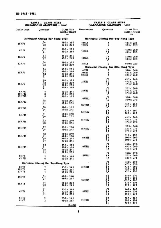
Alloys, Extruded Round Tube and HollowSections (For General Engineering Purposes).They shall conform to the dimensions shownin Fig. 5.5.3 Glass Panes - Glass panes shall wcigh atleast 7'5 kg/rn l and shall be free from flaws,specks, or bubbles. All panes shall have properlysquared corners and straight edgcs. The sizesof the glass panes for use in doors, windows andventilators shall be as given in Table I.
NOTE - The metal doors and windows industry hasfollowed the practice of the glazing industry in specifying size of glass. Accordingly, in the metal doorsand window s, the practice hitherto has been to specifythe height first and the width afterwards. I n thebuilding industry and in the case of timber doors andwindows the practice is to specify width first and heightafterwards. The Committee responsible for the preparation of this standard has considered it desirableto unify the practice in this regard and has adopted thebuilding industry practice, that is, to specify widthfirst and height afterwards.
5.4 Screws - Screw threads of machine screwsused in thc manufacture of aluminium doors,windows and ventilators shall conform to therequirements of ·IS: 1362-1959 Dimensions forScrew Threads for General Purposes (DiameterRange 0·25 to 39 mm). Other threads shall bepermissible if agreed to between the purchaserand the vendor.
6. FABRICATION
6.1 Frames - Frames shall be square and flat,the corners of the frame being fabricated to atrue right angle. Both the fixed and openingframes shall be constructed of sections whichhave been cut to length, mitred and welded atthe corners. Where hollow sections are usedwith welded joints, argon-arc welding or flashbutt welding shall be employed ( gas welding orbrazing not to be done). Subdividing bars ofunits shall be tenoned and riveted into theframe.
6.1.1 The location of the parts of the door ....windows and ventilators for which de..tails offabrication arc described under 6.1.2 are indicated in Fig. 6 (Set P 9).
.Since revised and withdrawn.

GlA
ZIN
GB
AR
Al-
T8
0-36
3kg
/m
• i ~i.. rtJ
1~~t-JOj..-t~
.,I~
"W
tN..
14='"
12·'
L33-
3O
PE
NIN
GFR
AM
EA
l-CF
60-
&14
kg
jrn
rt---·6
-0---l
jI
2...
~21L-2~
-l-12.'
MU
LLIO
NB
AR
Al-
F4
80-
837
kg
/m
3-~
I-as
••J'
~ L_
3-2-
11
1--2
2-2
GlA
ZIN
GB
AR
At-
T'
0-33
4kg
!m
[[}==1
J.~~
Jr
GlA
ZIN
GB
AR
At-
T6
0-30
6kg
/m
INS
IDE
FRA
ME
BA
RA
t-F
X6
1-03
3kg
/m
...C
OU
PLI
NG
WIT
HW
EA
TH
ER
BA
RA
I-H
K12
81-
61kl/
m
ls-sr-'~01=fl
8-4
N
3..
J.L
22.2--
-lI
C=44-4~
tSD
EFR
AM
EB
AR
At-
FX
S1-
033
kg
/m
t:1'
No
n2
-T
he
wei
ghts
orse
ctio
nsp
erm
etre
leng
thas
indi
cate
dar
eno
min
al.
All
dim
ensi
ons
inm
il1i
met
res.
FIG
.5
ExT
aU
DE
DA
LU
MIN
IU..
SE
CT
ION
SP
Oa
Doo
as.
WIN
DO
WS
AN
DV
EN
TIL
AT
OR
S

IS: 1948 - 1961
TABLE I GLASS SIZES TABLE I GLASS SIZES(CLEARANCE ALLOWED) (CLEARANCE ALLOWED) - Con/d
(Cklus, 5.3) DESIGNATION QUANTITY (~L.\SS SIZEWidth ~ Height
DESIGNATION QUANTITY GLASS SIZE emWidth X Height
No Glalnt Bar Centre-Hunt Typeem6NC6 1 46·0x 46'0
No Gwlnt Bar Flzed Type .tONC6 2 42·5 x 46·0t2SC6 2 52'5 x 46'0
6N....6 1 53'Ox 53·010NF6 2 45·0x 53·0 15SC6 {~ 45·0,< 53-012NF6 2 55·0x 53-0 43'S)~ 46'0
ISNF6 {~45-0x 53-6
18NC6 {~ 55·0/. 53·047·5 X 53-0 53·5 .'~ 46-0
18NF6 {f 55·0x 53-0 8NC6 66,0.< 46·057-5x 53-0
6NF9 1 53·0x 83·0 No Glaalnt Bar Side-Hunt TypetONF9 2 45·0>: 83·0
6~S9 I 50·0..< 80·012NF9 2 55-Ox 83-0 10NS9 2 43·5 x 80·0
{f 4!-Ox 83·0 12NS9 2 52·5;< 80·0t5NF9 47-5x 83-0
{~43·5 ;.: 80·0
{f 55-Ox 83·0ISNS9 47·5 x 83·0
18NF9 57-5X 83-018SS9 {~
52·Sx 80·06NF12 t 53-0xtI3'0 57·5 x 83-0
10NFt2 2 4S-0xt13-012NFt2 2 55-Ox113·0 6NSt2 1 50·0 x 110·0
{~45·0xlt3·0 tOSS12 2 43'5 y,110·0
t5NF12 47·5 x 113·0 12SS12 2 52·5 x 110·0
{~55·0xl13·0 ISNS12 {~ 43·5 x 110·0
18NFt2 57·5 x 113·0 47'5 x 113·0
6NFI5 {~53-Ox 27·0 18NS12 {~
52·5 x 110·053'Oxtl3-0 57·5 x 113·0
tONFIS {~4S'Ox 27·0
6SS15 {~53·0x 27-0
4S'Oxltl-O 50·0 x 110·0
12NFtS {~55·0x 27·0
{~45·0x 27·055·0x 113·0 10NS1S 43·S x 110·0
{~45-0 x 27-0
{~55·0x 27·0
15NFlS 47·5 x 27·0 12SS1S·45·0x 113-0 52·5 x 110·047·5 x Itl·O
H4S'Ox 27·0
H55·0x 27·0 15NSt5 47·5;{ 27·0
18NFlS 57·5 x 27·0 43·5 x 110·055·0x 113-0 47·5 x 113·057-5x 113·0
8NF6 1 73·0x 53-0 H55·0 x 27·057·!:< 27·018NStS 52·5 x 110·0
{!53·0x 84·5
6NF21 53·0x 27-5 57·5 x-l1J'O
53·0x 56·0
{! 66·0:< 81·0
No Glailla Bar Top-Huna Type8NS21 56·0x 27,';
66'Ox 56·06NT6 1 SO-Ox 50·0
H50-5x 81·010NT6 2 44·5 x 50·0 50·5 x 56·012NT6 2 54-5x 50·0 12NS21 50·5 x 27·5
tSNT6 {f 4S-0x 53·0 40·5 x 27·S45·5 x 50-0 Horizontal Glaalne Bar Fixed Type
tlNT6 {f SS'Ox 53·0 6HF6 2 53-0.>( 26·054·5x SO-O tOHF6 .. 45-0,< 26·0aXT6 1 70·0·x SO'O 12HF6 .. 55·0x 26·0
6NT9 {~SO-Ox 51-5 15HF6 {; 45·8x 260053·0x 27·5 47·5 x 26-0
(COtII4) (C<lnl4)
7
IS: 1948 .1961
TABLE I GLASS SIZES TABLE I GLASS SIZES(CLEARANCE ALLOWED) - Could (CLEARANCE ALLOWED). - Cot.,d
DESIG:-iATION QUANTITY GLASS SIZK DESIGNATION QUANTITY GLASS 51ZE\Vidth X Height \Vidth x Height
em em
Horbontal Glula, Bar FIxed Type Horizontal Glazln. Bar Top-Hun. Type
18H1o'6 {~55-Ox 26'0 10HC6 4 42'5 x 22·557·5 x 26·0 12HC6 4 52·5 x 22·5
6HF9 {~'i3'Ox 27·5
i5HC6 {; 45·0x 26·053-Ox 26·0 43-5 x 22·5
10HF9 {; 45·0x 27·5 {; 55·0x 26·045·0x 26·0 18HC6 53·5x 22'5
12HF9 {; 55'Ox 27·5 8HC6 2 66·0x 22-555-Ox 26·0
H45·0 x 27·5
Horizontal Gla.lna Bar Side-Hun, Type6H59 3 50·0x 26·0
15HF9 45·0x 26·0 10H59 6 43'5 x 26-047·5 x 27·547·,Sx 26·0 12H59 6 52·5 x 26·0
H55·0x 27·5 H 43·5 x 26·0
55·0x 26·0 ISHS9 47·5 x 27·518HF9 57·5 x 27·5 47·5 x 26·0
57·5 x 26·0
H 52'5 x 26·06HF12 4 53'Ox 27·5 18H59 57·5 x 27·5
10HF12 8 45·0x 27·5 57'5 x 26-012HF12 8 55·0x 27·5
{~SO-Ox 26·06H512
{~45·0 x 27·5 50·0 x 27·5
15HF12 47·5 x 27·5 {: 43·5 x 26·010H51218HI"12 {: 55·0x 27·5 43·5 x 27·5
57·5 x 27·5 {: 52·5 x 26·012H5126HFIS {l 53·0x 27·0 52·5 x 27·5
53·0x 27·5
H43·5 x 26·0
tOH.F1S {~45·0 x 27·0 15H512 43'5 x 27·5
45·0x 27·5 47'5 x 27'5
J2HI-"15 {~55·0x 27·0 H 52'5 x 26·055·0x 27·5 18HS12 52·5 x 27·5
57·5 x 27·5
H45·()x 27·0
H 53·0x 27·015HF15 47·5 x 27·045'Ox 27·5 6H5tS 50·0 x 26·047·5 x 27·5 50,0 x 27·5
H55·0x 27·0 H 45·0 x 27·0
18HF15 57·5 x 27·0 10H5tS 43·5x 26·055·0x 27·5 43·5 x 27·5
57·5 x 27·5 f2 55·0x 27·08HF6 2 73·0x 26·0 12H515 t: 52·5 x 26·06HF2t 6 53·0x 27·5 52·5 x 27·5
Horizontal Glazinl1 Bar Top-Huna Type
H45·0x 27·047·5 x 27·0
6HT6 2 50'Ox 2.J·5 15H515 43·5>( 26'010HT6 4 44·5 x 24·5 43'5 x 27·512H1'6 4 54·5 x 24·5 47·5 x 27·5
tSHT6 {; 45'Ox 26·0
H55·0x 27,0
44·S x 24·S 57·5 x 27·018H515 ..52·5 x 26·0
18HT6 {; 55'Ox 26·0 52'5 x 27·554'5 x 24·5 57'5 x 27·5
{! 50'Ox 26·0 H66·0x 24,0
6HT9 50'Ox 2.J·5 8H521 66-0x 27·553'Ox 27·5 56'Ox 27·5
8H1'6 2 70'Ox 24·5 H 50'5 x 24·06HC6 2 46·0x 22·5 12H521 50·5 x 27'5
40·5 x 27·5(Cem/d)
8

IS: 1948 - 1961
FOR DETAIL SEE FIG.IOTYPE 6HT9
FOR DETAIL SEE FIG.9
TYPE 6HF6/SHT6FOR DE.TAIL SEE FIG.II
..t
6HF6TYPE 6HSl2
FOR DETAIL SEE FIG.?TYPE ISHSI2
FOR DETAIL SEE FIG.12
FOR DETAILSEE FIG.f3
, 12HT6TYPE t2HS2I
TYPE 6HSISFIG. 6 LOCATION OF PAaTS oFALUNINIUIi DOORs, WINDOWS AND
VBNTILATORS FOR WHICH DETAILS ARB SHOWN
9

IS: 1948 - 19'1
FIG. 7 MULLION WIT.. I,'IXED ('LASS ON ONE SIDE ANDSIDS-HUNG ON OTHER SIL>I~
~ FIG. 8 MUI.LION WITH SIDE-HUNG SHUTTER BOTH SIDES
----- 50"'''' -----1
AL.-CI6
FIG. 12 \\"E.\THP.R BAR OVER 'EXTERNAL OPENINGSHUTTER WITH FIXEU LICHT ABOVE
FIG. 9 COUPLING SECTION EXTRUDED FOR COUPLINGWINDOWS SIDB BV 510£
FIG. 10 J)ET-'lL TIIROUGK BOTTOM OF TOP-HUNGVENTILATOR
6.1.2 Details of construction of doors, windowsand ventilators shall be as indicated in Fig. 7to 13 (see P 10 and 11).
6.2 Side-haa. SbaUer. - For fixing aluminium alloy hinges, slots shall be cut in the fixedframe and the hinges inserted inside and may beriveted to the frame. The hinges shall normallybe of the projecting type 67 mm wide(SII Fig. 14). The aluminium alloy for casthinges shall conform to IS Designation A-5-Mof IS: 617-1959 Specification for Aluminiumand Aluminium Alloy Ingots and Castings forGeneral Engineering Purposes ( Revised) and forextruded section of hinges to IS DesignationHEIO-WP or HE30-WP of-IS: 733-1956 Specification for Wrought Aluminium and AluminiumAlloys, Bars, Rods ana Sections (For GeneralEngineering Purposes). The pins for hingesshall be of stainless steel of non-magnetic type orof aluminium alloy HR30. Irrespective ofhinges being anodized or not, the aluminium alloypins shall be anodized to a minimum film thickness of 0'025 mm and shall be sealed with oil,wax or lanolin. Non-projecting types of hinges(Stt Fig. 15) may also be used, where agreed tobetween the purchaser and the supplier.
6.2.1 Friction hinges may be provided forside-hung shutter windows, in which case pegstay as mentioned under 6.2.3 may not be required. The working principle of the frictionhinge is illustrated in Fig. 16 (sI'e P. 12).
6.2.2 The handle for side-hung shutters shallbe of cast aluminium conforming to IS Designation A-S-M of IS: 617-1959 Specification forAluminium and Aluminium Alloy Ingots andCastings for General Engineering Pnrposes (Ret1ised) and mounted on a handle plate welded orriveted to the opening frame in such a way thatit could be fixed before the shutter is glazed.The handle should have anodized finish withminimum anodic film thickness of 0·015 mm.The hanr.le shall have a two-point nose whichshall engage with an aluminium striking plate on
.Since revised.
MASTIC CEMENT
EXTRUDEDCOUPLING SECT'ON
PUTTY
WEATHER BAR.TWEEN VENTILATOR
AND WINDOW
FIG. t t COUPLING SECTION EXTRUDED HAVINGWEATHER BAR Jo'ITTED WITH \'JtNTILATORB ON rol'
OF WINDOW.
10

IS: 1948-1".
VllTICAL SECTION OP DOOR
ubmfQ:o-INSIDE
HORIZON,.AL SECTION 0' DOOR
FlG. 13 DETAIL OF AJ..UIUNIUM DouaLE SHUTTER Doo.
FIG. 14 TVPICAL PaOJ.CTU'O Tv•• 11I.0& woaS~E.Hu~o SHun..
11
Flo. 15 TVPICAL XOX-PROJ&CTING TY.E Huco• .-oaSID&·HV~G SHUTTSR

(
18:1948.1%1
.'MoILI" ITlIL W"IMPiI.-_-::'&iLI--.IN ~I I'lCK TO lACK
.,," ""'10 .,.,ACti
FIG. 16 ILLUSTRATION SHOWING WORKING PRINCIPLE OFFRICTION HINGES
rEu
'"~•
L~9 MODULE (17-Scm)
HIGH WINDOWS
FIXING KAIW
SHAKE PROOfWASHER
10-3"""
FIG.17 A TYPICAL HANDLE If'OR SIDE-HuNG SHuns.
f ..............
12 MODULE (117-5 em)HIGH WINDOWS
FIG. 18 ~ITIOJl _ HAJI-=- PLATa I. R&LATIO.TO HalGHn ow• HS ' TYpa OW WUCDOWS
,-J
• ",,,,PIN
....---71.... ---.......- .........~m~•
- ........~-...;,-.-LOCKING MACKET
--........" ...+6S......I--=7S....----....
...------------100"'''' ------------..• ·IG. 19 It. TYPICAL P&G STAY FOR SIDE-HUNG SHUTTBas AND Top-HUNG VENTILAToa.
the ftx('d frame in a ~lightly open position as wella.., in a fast position (sec }4"ig. 17 on P 12). Theheight of the handles in each type of side-hungshutters shall be fixed in approximate positions asindicated in Fig. 18 (s,"~ P 12).
6.1.3 The peg stav shall be either of cast aluminiun, ronfornu1l9 to IS Designation A-S-ltl ofIS: 617-1959 S()flClflcation for Aluminium and
Aluminhlm Alloy Ingots and Castings for GeneralEngineering Purposes (Rtt'isttl), or folded from ISDesignation NS4 aluminium alloy sheet conforming to -IS: 737-1955 Spedficatiun for \VroughtAluminium and Aluminium Allo)'s, Sheet andStrip (For General Engineering Purposes]. Itshall be 300 rom long, complete with peg and lock-
• Second revision in 1974.
12
IS: 1948-1961
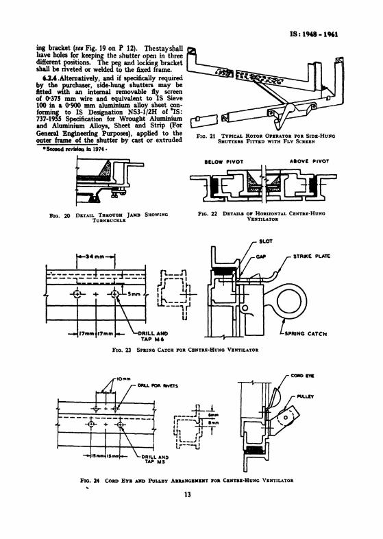
inc bracket (see Fig. 19 on P 12). Thestayshall~have holes for keeping the shutter open in threedifferent llOsitions. The peg and locking bracketsball be nveted or welded to the faxed frame. ~
6.3.4.Alternatively, and if specifically required _~-.i___by the ~urchaser, side-hung shutters may befttted WIth an internal removable iy screenof 0·375 mm wire and equivalent to IS Sieve100 in a 0'900 mm aluminium alloy sheet conforming to IS Designation NS3-1/2H of -IS:737-1955 Specification for Wrought Aluminium ,..0----1and Aluminium Alloys, Sheet and Strip (For L:----'General Engineering Purposes), applied to the FIG. 21 TYPICAL ROTOR OPERATOR FOR SIDE..HUNGouter frame of the shutter by cast or extruded SHUTTERS FITTED WITH FLY SCREItN
·SecoDd rcvi.ioa in 1974.
IlLOW PIVOT AIOVE PIVOT
FlG. 20 DETAIL THItOUGH JAIIB SHOWINGTURNBUCKLE
DAILLANOTAP M6
FIG. 22 DItTAJLS OF HORIZONTAL CENTRE-HUNGVENTILATOR
FIG. 23 SPRING CATCH FOR CENTRE-HUNG VENTILATOR
-lL-!.r---.:r-~:r---~''''"'•., II T~: r,.,• '---_.I I
lr---uDRILL AND
TAP WI
FIG. 24 CORD Eya AND PuLLEY AIUtANGEMENT FOR CBNTRE-HUNG VENTILATOR
13

IS: 1948 - 1961
FIG. 25 TVPIC.'L PROJECTING TYPB HINGE PO. DOOR
FIG. 26 T\'PICAL ~O~·PROJECTI~G TVPE HUlaE FORDooa
aluminium alloy turn-buckle at the jambs (seeFig. 20) and by aluminhaID or plated bronze(gun metal) shoes at the sill to allow of thescreen being readily removed: and with a .rotoroperator at the sin to permit the operation of thesflutter throu«h an angle of goo(,,, Fig. 21). Onfty-screened shutters the peg stay..is omitted andthe normal handJ~ shall be replaced by a lockinghandle to hold the shutter in the fast position.
6.a Top-Hua. Veatllatora- The alummiumhinges ior top;.hung ,"entilators shall be eithercast or fabricated out of extruded sections andshall be riveted to the fixed rail aftet: cutting aslot in it. The aluminium alloy for cast hingesshall confonn to IS Designation A-S-Af ofIS: 617..1959 Specification for Aluminium andAluminiulIl Alloy Ingots and Castings for General Engineering Purposes (RlIJisetl), and for extruded section of hinge to IS Desipation HE10WP or HE30-WP of -IS: 733-1956 Specificationfor Wrought Aluminium and Alumimum Alloys,Ban, R.ods and Sections ( For General Engineer.ing Purposes).
6.3.1 The peg stay shall be 300 mm long asin siqe-hung shutter (SII Fig. 19 ). The lockingbracket shall be fixed to the fixed frame.6.4 Centre-Huaa VentU.tore - Centre-hungventilators (se, Fig. 22) shall be hung on twopairs of cup pivots qf aluminium alloy to ISDesignation NS-4 of TIS: 737-1955 Specificationfor Wrought Aluminium and Aluminium Alloys,
·Since rc-viled.tSecoDd revi.ionlD 1974.
-$ ].
I
0 QOUTIIDI VIIW INIIO& VIIW
FIG. 27 TY'PICAL Tlftn. HANDLS
14
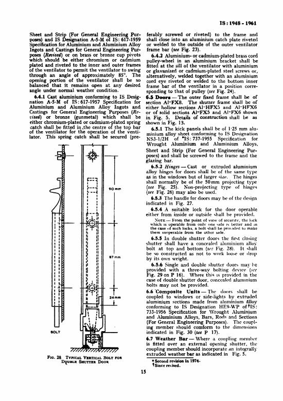
FIG. 28 TYPICAL VERTICAL BOLT FORDq,UBLE SHUTTER DOOR
Sheet and Strip (For General Engineering Purposes) and IS Designation A-5-M of IS: 617-1959Specification for Aluminium and Aluminium AlloyIngots and Castings for General Engineering Purposes (Revised) or on brass or bronze cup pivotswhich should be either chromium or cadmiumplated and riveted to the inner and outer framesof the ventilator to permit the ventilator to swingthrough an angle of approximately 85°. Theopening portion of the ventilator shall be sobalanced that it remains open at any desiredangle under normal weather condition.
6.4.1 Cast aluminium conforming to IS Designation A-S-M of IS: 617-1957 Specification forAluminium and Aluminium Alloy Ingots andCastings for General Engineering Purposes (Ret';sed) or bronze (gunmetal) which shall betither chromium-plated or cadmium-plated springcatch shall be fitted in ,the centre of the top barof the ventilator for the operation of the ventilator. This spring catch shall be secured (pre-
LJ.LIIt
BOl.T
IS: 1948· 1961
ferably screwed or riveted) to the frame andshall close into an aluminium catch plate rivetedor welded to the outside of the outer ventilatorframe bar (see Fig. 23).
6.4.1 Aluminium- or cadmium-plated brass cordpuller-wheel in an aluminium bracket shall befittec at the sill of the ventilator with aluminiumor glavanized or cadmium-plated steel screws or,alternatively, welded together with an aluminiumcord eye riveted or welded to the bottom innerframe bar of the ventilator in a position corresponding to that of pulley (see Fig. 24).6.5 Door. - The outer fixed frame shall be ofsection AI-FX8. The shutter frame shall be ofeither hollow sections AI-HFX5 and AI-HFX6or of solid sections AI-FX5 and AI-FX6 shownin Fig. 5. Details of construction shall be asshown in Fig. 13.
6.5.1 The kick panels shall be of 1'25 mm aluminium alloy sheet conforming to IS DesignationNS3-1j2H of ~S: 737-1955 Specification forWrought Aluminium and Aluminium Alloys,Sheet and Strip (For General Engineering Purposes) and shall be screwed to the frame and theglazing bar.
6.5.1 Hinges - Cast or extruded aluminiumalloy hinges for doors shall be of the same typeas in the windows but of larger <iz«, The hingesshall normally be of the SOmm projecting type(see Fig. 25). Non-projecting type of hinges(sie Fig. 26) may also be used.
6.5.3 The handle for doors may be of the designindicated in Fig. 27.
6.5.4 A suitable lock for the door operableeither from inside or outside shall be provided,
XOTE - From the point of V1CW of securrtv, the lockwhich IS operable from onlv one vide I') better and 1I1
the case of such locks, a holt "hall be prm idod to makethem Inoperable from the other side.
6.5.5 In double shutter doors the fir... t closingshutter shall have a concealed aluminium allovbolt at top and bottom (sec Fig. 28). It ... hailbe so constructed as not to work loose or dropby its own weight.
6.5.6 Single and double shutter doors may heprovided with a three-way bolting device (~CC
Fig. 29 on P 16). Where this IS provided in thecase of double shutter door, concealed alummiurnbolts may not be provided.6.6 'Composite Uaits - The doors shall becoupled to windows or side-lights by extrudedaluminium sections made from aluminium c\lJoyconforming to IS Designation HE9- \\'P of tIS:733-1956 Specification for \Vrought Aluminiumand Aluminium Alloys, Bars, Rods and Sections(For General Engineering Purposes). The coupling member should comfonn to the dimensionsindicated in Fig. 30 (see P 17).6.7 Weather Bar - Where a coupling memberis fitted over an external opening shutter. thecoupling member should incorporate an integrallyextruded weather bar as indicated in Fig. 5.
• Second revision in 1974.'Since re\ised.
15

IS: 1948 - 1961
uPPER LOCKINGSTRIP
LIVER
GUIDE Pit RIVE. TED10 THE SECTIONAT T" lANK
DOD
I
5TRIP-a' RIVETEO TOLOCKING STRF
nFIG. 29 TYPIC.-\L THllEE-WAY BoLTING DEVICE POR DOORS
16

18: 1948 - 1961
7. POSITION 0 .. BOLTS,PIXING SCREWS AND LUGS
7.1 Outer frames shall be provided with fixingholes centrally in the web of the sections in theposition indicated in Fig. 31 (see P 17). Moreo,"er,any steel lugs coming in contact with aluminiums~oul~ be either galvanized or given one coat ofbituminous paint.
FIG. 30 COUPLU'G 5acrioN EXTaUDED POll COUPLING 7.1 The fixing screws and lugs shall be as given inDoo. TO WIKDOW O. SID. LIGHT Table 11 (Stt P 18).
B~5 ~9"'5~ 4;""'?r t: I4
7-5-----t :h='770'----t11·1 "., "., ' ,t"T1k r- -j r-' ., 1*'1"5Io-'-If r-6907-r69-71 i
sL1: tD OJ on onr-tf:rD: ..
17·5I .L.L..l!jL mm ITO OJ]
mm--
I
..
- ,
All dimensions in centimetres.
FIG. 31 CHART SHOWING ApPROXIMATE PosITIONS OFFIXUIG HOLES AND NUMBER 0,. FI.XI~G LeGS
8. FINISH8.1 Aluminium door." \\ indows and ventilatorsmay be supplied in either matt, scratch-brush orpolished finis-h. They may. additionally. also beunodized, if so required by the purchase-r. Ifcolour anodizing is to be done then only approvedlight-fast shades should be used.8.1 A thick layer of dear transparent lacquerbased on m~thacrylates or cellulose butyrate,shall be applied on aluminium doors, window sand ventilator!' by the suppliers to protect thesurface from wet cement during installation.This lacquer coating shall be removed after installation is completed.
•• GLAZING'.1 Gluing shall be provided on the outside ofthe frames.
17

18: 1948 - 1961
FIG. 32 F,XING SCREW FOR \VOODEN FRAil" oa PLUO'IN COXCIlET&
~,'00.....
"'---70--.....
AU dimensions in millimetre••
FIG. 33 SLOTTED FIXING LUG
(FOR BRICKWORK AND MUONRY)
TABLE II FIXING SCREWS AND LUGS
(Clause 7.2)
I
20t
II
AU dimenuonl in miUimetrel.
Flo. 34 FIXUIG CLIP FOR STaaL WORK
PUTTY
PUTTY
FIG. 35 GLAZnlG CLIPS
SL PLACE OF FIXINGNo.
r) 'Co wooden frames rebated on the outside
Ji) T~ plugs in concrete,stone or brick work rebated on the outside
Iii) To plugs in concrete,stone or brick work notrebated on the outside(that iii plain or squarejambs)
IV) Direct to brick work ormasenry (that is plainor sq uare jambs)
v] To steel work
SIZE OF SCREW OR LUG
30 mm X No. 10 galvanized wood-lCrews(st'e Fi,. 32)
do
45 mm X No. 10 .alvanized wood-screws
Slotted steel adjustablelugl (natural finish)not leu than tOO x 16)( 3 mm countersunk
,alvaDiaed machinescrewl and nuts 19·0x6'3 mm (...ee lo~ig. 33)
Standard clips and 8 mm~al\'anized bolts withhexagonal nuts (se,Fi•. 34)
18
9.1.1 If required. glazing clips (," Fig. 35on p. 18) may be provided as extra fittings by mutual arrangement between the purchaser and thesupplier. Four glazing clips may be providedper glass pane, tX~t for door type 8H521where the glazing clips shan be six per glasspane. In case of doors, windows and yentilatonwithout horizontal glazing bars the gluin, clipsshall be spaced according to the slots In thevertical members, otherwise, the spacing shallbe 30 em. r
NOTB- GladD, clips are not ulually provided fornormal size .laIa paDeI_ Where larse size .luI pae_are required tobe uaed or where the door or the Windowi.located in he&vill expoeed situadou, bola for ,lulu,clip' have to be dnllecl prior to fabrication aDd canDOtbe dODe at any later Itqe. U. of llazial ellpl. wbeNnee...,,>,.shall be apecilecl while placiD, the order.
18. PAClJNG
18.1 All doors. windows and ventilaton sha11 be

despatched with the opening pans suitablysecured to preserve alignment when fixing andgluin,.1• .2 Fixing lugs, coupling fittings and all hardware shall be despatched separately.
1• .1 Composite windows shall be despatcheduncoupled.
II. MARING11.1 AU doors, windows and ventilators shall besuitably marked on the frames with a markidentifying the manufacturer and the type.
19
IS: 1948 .1961
11.1.1 The units may al90 be marked with thelSI CertiAcation Mark.
NOTa-The use or the lSI Certificaboa Mark iIpvemed by the provisions or the Indian StaDdardtInsLitution (Certi&catiOD Mara) Act, and the Rulaand Rqulationl made thereUDder. Presence or thismark on produces covered by an Indian StaDdardCOOYeyl the aaurance that they have beea produced tocomply with the requiremeDti 01 ahat .tandard, unclera weD-de&ned .yatem of iDapection, tatin, aDd qualityconrrol durq production. This lyltem, which isdevited and .uperviled by lSI aDd operated by theproduc., bu the further ,afepard that the productsu actually marketed are continuoual, checked by lSIfor conformity to the .tandard. Detaill of condition.,under which a licence lor the ute 01 the lSI CenificadoaMark may be pnted to manuractUftl"l or~may be obtained lrolD the Indian Standard. lasdtution.
Bureau of Indian Standards
BIS is a statutory institution established under the Bureau 0/ Indian Standards Act, 1986 to promoteharmonious development of the activities of standardization, marking and quality certification of goodsand attending to connected matters in the country.
Copyright
BIS has the copyright of all its publications. No part of these publications may be reproduced in any formwithout the prior permission in writing of BIS. This does not preclude the free use, in the course ofimplementing the standard, of necessary details, such as symbols and sizes, type or grade designations.Enquiries relating to copyright be addressed to the Director (Publications), BIS.
Review of Indian Standards
Amendments are issued to standards as the need arises on the basis of comments. Standards are also reviewedperiodically; a standard along with amendments is reaffirmed when such review indicates that no changes areneeded; if the review indicates that changes are needed, it is taken up for revision. Users of Indian Standardsshould ascertain that they are in possession of the latest amendments or edition by referring to the latest issue of'BIS Catalogue' and 'Standards: Monthly Additions'.
This Indian Standard has been developed from Doc : No.
Amendments Issued Since Publication
Amend No. Date of Issue Text Affected
BUREAU OF INDIAN STANDARDS
Headquarters :
Manak Bhavan, 9 Bahadur Shah Zafar Marg, New Delhi 110 002Telephones: 2323 0 I 31, 2323 33 75, 2323 94 02
Telegrams: Manaksanstha(Common to all offices)
Regional Offices:
Central : Manak Bhavan, 9 Bahadur Shah Zafar MargNEW DELHI 110002
: C.J.T. Campus, IV Cross Road, CHENNAI 600 113
: seo 335-336, Sector 34-A, CHANDIGARH 160022
: 1/14 CJ.T. Scheme VII M, V. I. P. Road, KankurgachiKOLKATA 700 054
Telephone
{2323 76 1723233841
{2337 8499,2337 85 612337 8626,233791 20
{260 38 432609285
{2254 12 16,2254 1442225425 19,225423 15
: Manakalaya, E9 MIDC, Marol, Andheri (East) { 2832 92 95, 2832 78 58MUMBAI 400 093 2832 78 91, 2832 78 92
AHMEDABAD. BANGALORE. BHOPAL. BHUBANESHWAR. COIMBATORE. FARIDABAD.GHAZIABAD. GUWAHATI. HYDERABAD. JAIPUR. KANPUR. LUCKNOW. NAGPUR.NALAGARH. PATNA. PUNE. RAJKOT. THIRUVANANTHAPURAM. VISAKHAPATNAM.
Western
Branches:
Southern
Eastern
Northern