technical seminar for cathodic protection to gogc design unit
TRANSCRIPT
Technical Seminar for Cathodic Protection
to GOGC Design Unit Specialists
Dr. Nick Kioupis, Cathodic & Lightning Protection
Section Head, DESFA

CP Design Criteria
Pre-requisites for the application of cathodic protection
– Electrical continuity
– Electrical isolation
– Lightning and overvoltage protection
– Coating
– Selection of pipe trench backfill material
– Buried casings for pipelines
– Equipment for the reduction of a.c. interference
– Equipment for the mitigation of d.c. interference

Electrical Continuity
Low longitudinal resistance of the pipeline and the components which may
increase the longitudinal resistance of the structure shall be short-circuited.
On non-welded pipelines, the electrical continuity shall be achieved on the
length to be protected by the installation of permanent bonds across the
high resistance mechanical connectors using reliable bond attachment
methods. The continuity of non-welded pipelines shall be checked by carrying
out resistance and potential measurements
When necessary, bonding may be carried out across isolating devices for
measurement or other purposes. If it is necessary that electrical continuity be
established permanently, this bonding should be done in a test station.

Electrical Isolation
Locations
Requirements for isolating joints
Internal corrosion risks at isolating joints
Contacts between metallic structures
Electrical earthing system

Electrical Isolation
• Metallic contacts or resistive contacts between the pipeline and other
structures, or direct connection to earthing systems, should be avoided;
otherwise, the corrosion risk can be increased.
• For this reason, pipelines should be electrically isolated from compressor
stations, pump stations, wellsites, offshore pipelines and structures,
terminals and processing facilities. Isolation should be achieved by
installation of monolithic (mono-bloc) isolation joints, isolating flange kits or
non conductive pipe sections.
• If electrical isolation is not possible, then the cathodic protection design
shall provide for sufficient current and effective current distribution to ensure
that the pipeline is cathodically protected without adverse effect on other
structures.

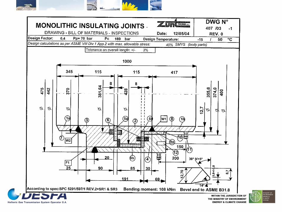
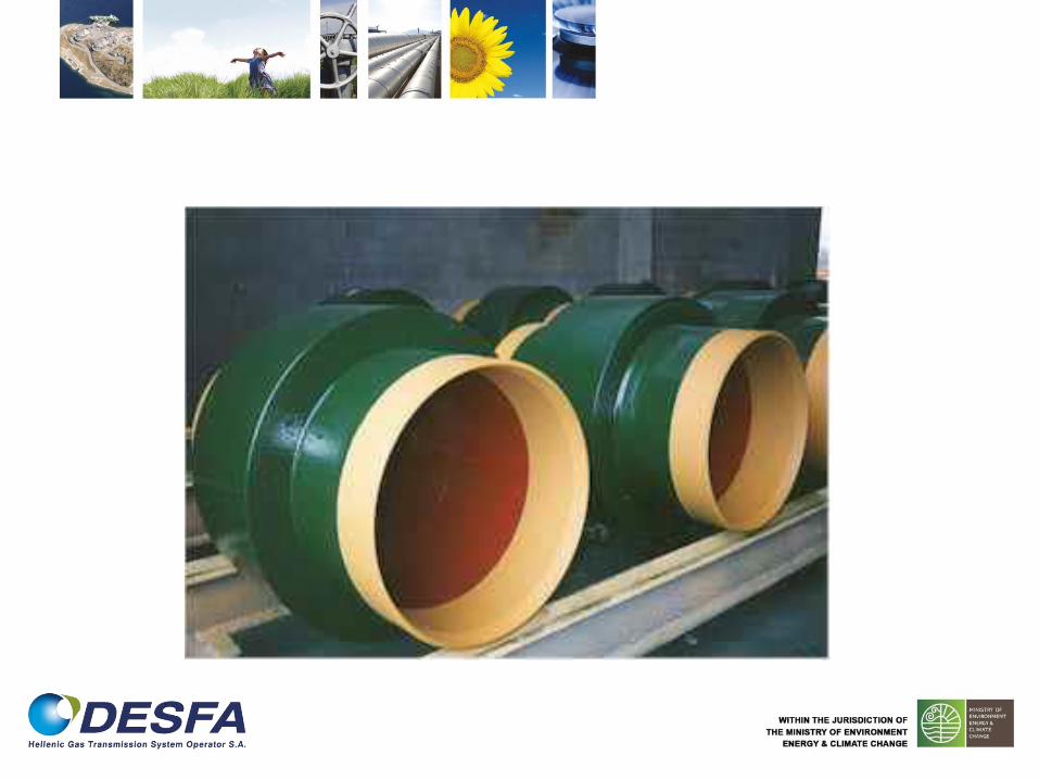
Monolithic (monoblock) IJ
DESCRIPTION
ΜΟΝΧΣΙΚΟ ΤΝΔΕΜΟ (Μ)
ΚΑΛΧΔΙΟ ΤΝΔΕΗ
ΠΙΝΘΗΡΙΣΗ
ΑΝΣΙΕΚΡΗΚΣΙΚΟ
ΠΙΝΘΗΡΙΣΗ
PIN BRAZING
ΠΕΡΙΓΡΑΦΗ
ΧΛΗΝΧΣΟ ΑΚΡΟ Μ
ΔΑΚΣΤΛΙΟ Μ
ΔΑΚΣΤΛΙΟ Μ
ΔΑΚΣΤΛΙΟ ΤΓΚΡΑΣΗΗ Μ
ΜΟΝΧΣΙΚΟ ΑΠΟΣΑΣΗ
ΣΕΓΑΝΧΣΙΚΟ ΔΑΚΣΤΛΙΟ
(O-RING)
ΕΞΧΣΕΡΙΚΗ ΕΠΙΚΑΛΤΦΗ
ΕΧΣΕΡΙΚΟ ΕΠΙΥΡΙΜΑ
ΜΟΝΧΣΙΚΟ ΓΕΜΙΜΑ
ΟΠΕ ΤΝΔΕΗ ΕΚΣΑΚΣΟΤ
ΑΝΑΓΚΗ ΣΕΓΑΝΧΣΙΚΟΤ
ΤΚΟΛΛΗΗ
ΑΓΧΓΟ

Schematic of insulating flange
Isolating flange with Ex-proof spark gap
(U50Hz=1kV, U1/50μs=2.2kV, surge current =100kA)
1. Isolating flange,
2. Hexagonal nut,
3. Insulator ring,
4. Insulator sleeve,
5. Insulator disc,
6. Steel disc
7. Isolating sealing gasket,
8. Spark gap


Electrical Isolation - Locations
between pipeline sections consisting of different metallic
materials;
at the extremities of the pipeline;
at significant changes in electrolyte resistivity;
on pipelines requiring different cathodic protection systems;
on pipelines with different current density requirements;
in areas influenced by stray currents, a.c. or telluric currents;
on some pipeline networks to facilitate the cathodic protection
maintenance or measurements;
at interfaces with unprotected structures or earthed equipment
at the interface with customer facilities
Requirements for isolating joints
The mechanical design, materials, dimensions and construction of the
isolating joints shall meet the requirements of ISO 13623, EN 14161,
EN 1594 or EN 12007-3, as applicable. Isolating joints should be
electrically tested before installation.

Requirements for isolating joints
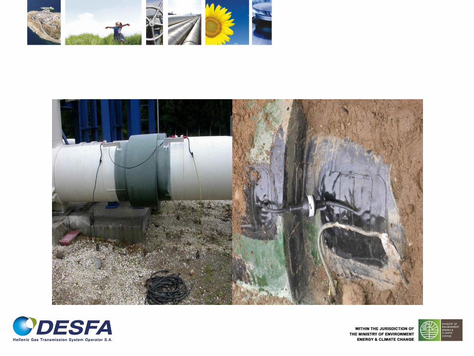
Monobloc isolation joints should be used wherever possible. They
may be installed above-ground, in a pit (where local safety
regulations permit) or buried.
Installing the isolation joint above ground provides the advantage
of easier visual, electrical and ultrasonic inspection. On the other
hand, buried isolating joints are less exposed to mechanical or fire
hazards, voluntary or involuntary damage and can prevent the
product inside the pipeline from freezing (sometimes referred to as
"frost-proof grounding").
Installing an isolating joint in a pit provides the advantages of a
buried isolation joint but with the added risk of gas entrapment. For
this reason, local regulations can prevent installation of an isolation
joint in a pit.

Requirements for isolating joints
When a pipeline is connected to above-ground facilities, an above-ground
isolating joint ensures that cathodic protection is applied to the entire buried
section. If the isolation joint is buried, then the pipeline operator shall take
additional measures for corrosion protection of the section of the pipeline
that is isolated from the main cathodic protection system.
If multiphase fluids containing a significant percentage of water are
transported in the pipeline, installation of the isolating joint on a vertical or
angled transition section may be considered to prevent a continuous water
phase inside the pipeline becoming the source of internal corrosion
Buried isolation joints shall be externally coated with materials that are
compatible with the coating applied to the pipeline.

Requirements for isolating flanges
Isolating flanges are subject to degradation by atmospheric
weathering, dirt and moisture ingress and shall be protected
against ingress of dirt and moisture by the use of flange
protectors or viscoelastic compounds.
A major cause of failure of isolating flanges is poor installation
techniques. To reduce this risk, the manufacturer’s instructions
should be followed or factory preinstalled kits can be utilized.

Requirements for isolating flanges
Principal installation errors are:
over-tightening of the flange bolts (isolating flanges
require a lower tightening torque than flanges without
isolating gaskets);
incorrect alignment of flange faces;
Improper surface preparation of flange faces

Requirements for isolating joints
withstand service conditions (e.g. transported medium, temperature, pressure,
mechanical stress)
appropriate dielectric strength.
mechanical (e.g. flexural and tensile strength, etc.),
isolation efficiency
water absorption.

Requirements for isolating joints
Isolating joints shall be installed in such a manner as to eliminate the risk
of accidental shorting.
To avoid damage from high voltages due to lightning strikes or a.c. fault
currents caused by electric power lines, protective devices shall be
considered (e.g. appropriate isolating spark gap, surge protective device
and appropriate electrical earthing).
Isolating joints installed in areas classified as hazardous in accordance
with EN 60079-10-1 shall conform to the certification and operational
requirements of the hazardous area.
Isolating joints shall be provided with accessible test facilities.

Internal corrosion risks at isolating joints
In pipelines carrying fluids with a separate water phase, there is a risk of
internal corrosion caused by current leaving the internal surface of the pipe
close to the isolating joint on the side that has a less negative internal potential
(anodic side). This is mainly dependent on the conductivity of the fluid and the
voltage between both sides of the isolating joint.

Contacts between metallic structures
Where entries, restraints, supports and anchors are made of concrete, there should be no contact (direct or resistive) between reinforcing steel and the protected pipeline. For this reason, an adequate wall entry fitting made of insulating material should be provided and a high-quality coating should be applied to the protected structure. The possibility of shielding effect shall be considered. In other cases, the structure shall be considered as a complex structure as defined in EN 14505.
Where the pipeline crosses a bridge above-ground or enters a tunnel, if there are isolating joints at each end of the bridge or the tunnel, the pipe between isolating joints may be equipotentially bonded to the bridge or the tunnel to provide protection from inadmissible touch potentials. In this case, in order to provide cathodic protection to the pipeline on either side of the bridge or the tunnel from a common cathodic protection system, an equipotential bond is required to connect the pipeline on both sides of the bridge or the tunnel.
If the pipeline crosses a bridge in a service trough containing an electrolyte (e.g. sand), the pipe may be cathodically protected by galvanic anodes (e.g. magnesium ribbon) and not connected to the bridge.
If there are no isolating joints, then the pipe shall be electrically isolated from the metallic parts of the bridge or the tunnel. This is especially important in the case of metal bridges carrying d.c. traction systems.
Electrical Earthing Systems
If an earthing system is required, it shall be made compatible with the cathodic protection system. When allowed by regulations, this may be achieved by installing suitably rated d.c. decoupling devices in the earthing circuit. Local earthing using zinc or galvanized earth electrodes directly connected to the pipeline may be used, but there can still be future adverse effects on the cathodic protection.
NOTE 1 These adverse effects on cathodic protection effectiveness are due to one or both of the following.
The resistance of local earth, with respect to remote earth, can be much lower than the resistance of coating defects, which results in reduced CP current at the coating defect.
Zinc or galvanized steel potential can drift with time towards less negative potentials.
If earthing is being installed to mitigate the effect of a.c. voltages on the pipeline, the earthing locations should be established through a specific study and detailed design.
NOTE 2 EN 15280 and EN 50443 provide guidance on the corrosion and safety related with a.c.
influences

Electrical earthing system
a) isolation of the electrically operated equipment from the protected structure;
b) isolation of the part of the pipeline (e.g. the valve) connected with the electrical operated equipment from the rest of the pipeline by means of isolating joints, with a continuity bond between the two parts of the pipeline and separate corrosion protection for the valve;
c) installation of isolating transformers;
d) installation of fault current circuit breaker in conjunction with a local earthing made of galvanized steel, zinc or magnesium;
e) installation of d.c. decoupling devices between the electrically operated equipment and the main earthing system (e.g. isolating spark gaps, surge protective device, polarization cell, electrical isolation).

Basic requirements for cathodic protection design
pipeline diameter;
pipeline length and wall thickness,
design life of the pipeline;
pipeline coating type;
field joint coating details;
location of above ground installations (e.g. pressure reducing station);
location of any valves;
details of any local earthing (e.g. at powered valves);
details of medium being carried;
operating temperature of the transported medium;
Basic info

Basic requirements for cathodic protection design
topographical details;
elevations;
electrolyte conditions (this may include electrolyte resistivity, pH, bacterial
activity);
results of stray current surveys in electrolyte;
presence of high-voltage overhead power lines;
known buried cables and structures including other pipelines;
any known adjacent cathodic protection systems;
river crossings;
road and railway crossings
Basic info

Basic requirements for cathodic protection design
casings that will remain after construction (length, material, coating if any);
types of pipeline bedding material;
bridge and tunnel crossings;
characteristics of a.c. and d.c. traction systems (e.g. sub-stations, operating
voltages);
characteristics of d.c. industrial plants;
any electrically operated equipment (e.g. emergency shut down valves).
Basic info

Basic requirements for cathodic protection design
Contents of cathodic protection design
report
design life of the cathodic protection system,
design documents justifying the sizing and layout of equipment (e.g. anodes,
transformer-rectifiers, cables),
potential attenuation calculations for justification of drain point spacing if any,
materials schedule,
materials specification,
synoptic scheme (single line diagram) of pipeline with significant features,
temporary cathodic protection systems

Basic requirements for cathodic protection design Contents of cathodic protection design
report installation procedures and connection details for all key elements.
1) anode groundbeds,
2) connections to anodes,
3) connections to pipe,
4) coating repairs,
5) electrical isolation, (monobloc, insulated flanges, insulated pipes),
6) transformer-rectifiers,
7) test stations,
8) a.c. mitigation systems,
9) sleeved crossings,
10) external probes, coupons or reference electrodes,
11) external electrical resistance probes,
12) bonds (equipotential, resistive and unidirectional),
13) drainage system,
14) remote monitoring or control

Basic requirements for cathodic protection design Contents of cathodic protection design
report
commissioning procedures,
operation and maintenance instructions
Basic requirements for cathodic protection design Cathodic protection current demand
Calculation of the theoretical total current demand
Current demand based on coating breakdown factors
Current demand based on current density values for coated pipelines

Basic requirements for cathodic protection design Cathodic protection current demand
k is a contingency factor due to possible non-uniform current distribution
along the pipeline, attenuation and shielding
j current density for bare steel

Basic requirements for cathodic protection design Cathodic protection current demand
fi is the initial coating breakdown factor at the start of pipeline operation,
f is the average yearly increase in the coating breakdown factor,
tdl is the design life time expressed in years
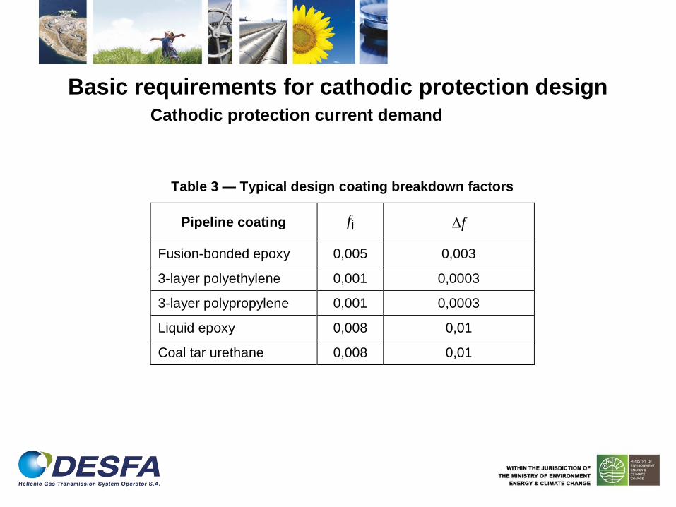
Basic requirements for cathodic protection design Cathodic protection current demand
Table 3 — Typical design coating breakdown factors
Pipeline coating fi f
Fusion-bonded epoxy 0,005 0,003
3-layer polyethylene 0,001 0,0003
3-layer polypropylene 0,001 0,0003
Liquid epoxy 0,008 0,01
Coal tar urethane 0,008 0,01

Basic requirements for cathodic protection design Cathodic protection current demand
jc current density for coated pipelines
rCO average coating resistance
jc = ΔE/rco
ΔE potential shift due to cathodic protection current measured
against a remote reference electrode
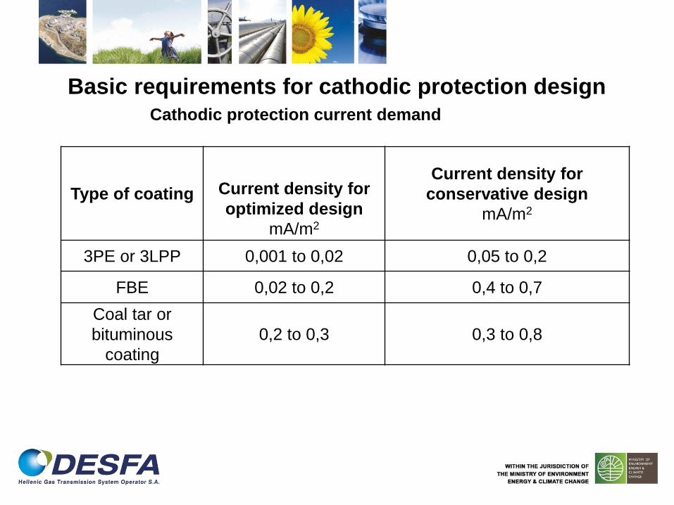
Basic requirements for cathodic protection design Cathodic protection current demand
Type of coating
Current density for
optimized design
mA/m2
Current density for
conservative design
mA/m2
3PE or 3LPP 0,001 to 0,02 0,05 to 0,2
FBE 0,02 to 0,2 0,4 to 0,7
Coal tar or
bituminous
coating
0,2 to 0,3 0,3 to 0,8

Basic requirements for cathodic protection design Cathodic protection equipment
Cathodic protection cables
o for buried service
o without metal armouring
o Cable cross sections
• voltage drops
• steady state current
• cable insulation properties
• mechanical strength
• flexibility
• operating temperature conditions
• economics

Basic requirements for cathodic protection design Cathodic protection equipment
Cathodic protection cables
Connections are typically made by
pin brazing,
soft-soldering,
adhesive bonding (only for measurement cables),
fusion-welding with metal deposit;
stud welding;
welding steel piece (e.g. doubler plate), directly on the pipeline, with a pre-
welded stud (or equivalent system);
thermit welding (e.g. aluminothermic).
Basic requirements for cathodic protection design Cathodic protection equipment
Cathodic protection cables
Welding of cable connections shall not be carried out on bends or within
200 mm from pipeline welds, fittings and valves.
Where thermic welding is used, the welding procedure shall ensure that
any copper penetration into the pipeline material is less than 1 mm and
that the local pipeline hardness remains within the limits of the pipe
specification.
The resistance of the connection excluding the resistance of the cable
should be below 0,1 Χ.

Basic requirements for cathodic protection design Temporary protection
installed in low resistive electrolyte (less than 100 Χ.m)
period between pipeline installation and permanent cathodic protection
exceeds 3 months
installed in areas where high corrosion risks have been identified
Both temporary and permanent galvanic anodes shall be connected to the pipe only
via above ground facilities.

Basic requirements for cathodic protection design Parallel Pipelines
• PROBLEM: Interference or shielding ??
• Common cathodic protection system??
Connection through diode or a series resistor
Location of groundbed
NOTE 1 Bonding parallel pipelines with widely differing cathodic protection current
demands will probably not be successful. In some cases separate cathodic protection
systems may be required.
NOTE 2 When measuring pipe-to-electrolyte potentials on parallel pipelines that are not
bonded, it is important that the reference electrode is located correctly.
Basic requirements for cathodic protection design Parallelism or crossing with a.c. power systems
In the case of long-term a.c. influence on metallic pipelines, it is possible
for a.c. to flow between bare metal (i.e. coating defect) and the
electrolyte. In these conditions, a.c. corrosion of metallic pipelines can
occur during normal operating conditions.
Damage to the pipeline and safety for personnel are covered in EN
50443. A.c. corrosion risk for cathodically protected pipelines is covered
in EN 15280.

Basic requirements for cathodic protection design Trenchless installation methods

Basic requirements for cathodic protection design Trenchless installation methods
Pipelines pulled through tunnels, installed by (trenchless) horizontal drilling
techniques are at risk of external coating damage caused during pulling. These
construction methods preclude detailed coating inspections or close interval
potential measurements once the pipeline section is installed.
Test facilities should be installed at either side of the crossing.
After the section has been grouted or backfilled, measurements should be
made to confirm the coating integrity.
If trenchless pipeline sections cannot be protected from the main cathodic
protection system, they should be electrically isolated and separately
cathodically protected.