technical report - computer science & engineering · structuring formal control systems...
TRANSCRIPT

Structuring Formal Control Systems Specifications for Reuse: Surviving Hardware Changes
Technical Report
Department of Computer Science
and Engineering
University of Minnesota
4-192 EECS Building
200 Union Street SE
Minneapolis, MN 55455-0159 USA
TR 00-004
Structuring Formal Control Systems Specifications for Reuse:
Surviving Hardware Changes
Jeffrey M. Thompson, Mats P. Heimdahl, and Debra M. Erickson
February 02, 2000

Stru turing Formal Control Systems Spe i� ations for Reuse:
Surviving Hardware Changes�
Je�rey M. Thompson, Mats P.E. Heimdahl and Debra M. Eri kson
Department of Computer S ien e and EngineeringUniversity of Minnesota
4-192 EE/CS; 200 Union Street S.E.Minneapolis, MN 55455 USA
+1 (612) 625-1381fthompson,heimdahl,eri ksong� s.umn.edu
Abstra t
Formal apture and analysis of the required behav-
ior of ontrol systems have many advantages. For in-
stan e, it en ourages rigorous requirements analysis,
the required behavior is unambiguously de�ned, and we
an assure that various safety properties are satis�ed.
Formal modeling is, however, a ostly and time on-
suming pro ess and if one ould reuse the formal mod-
els over a family of produ ts, signi� ant ost savings
would be realized.
In an ongoing proje t we are investigating how to
stru ture state-based models to a hieve a high level
of reusability a ross produ t families. In this paper
we dis uss a high-level stru ture of requirements mod-
els that a hieves reusability of the desired ontrol be-
havior a ross varying hardware platforms in a prod-
u t family. The stru turing approa h is demonstrated
through a ase study in the mobile roboti s domain
where the desired robot behavior is reused on two di-
verse platforms|one ommer ial mobile platform and
one build in-house. We use our language RSML�e to apture the ontrol behavior for reuse and our tool Nim-
bus to demonstrate how the formal spe i� ation an be
validated and used as a prototype on the two platforms.
Keywords: Requirements, Formal Models, Re-
quirements Reuse, Control Systems, RSML�e1 Introdu tion
Reuse of software engineering artifa ts a ross
proje ts has the potential to provide large ost sav-
�This work as been partially supported by NSF grants CCR-
9624324 and CCR-9615088, and by NASA grant NAG-1-2242.
ings. Traditionally, the resear h in the reuse ommu-
nity has fo used on how to onstru t reusable software
omponents, and how to lassify and organize these
omponents into libraries where they an be retrieved
for use in a parti ular appli ation. We know, however,
oding errors are not the main sour e of problems and
delays in a software proje t; in omplete, in onsistent,
in orre t, and poorly validated requirements are the
primary ulprit [4℄. Thus, we hypothesize that reuse
of requirements in onjun tion with reuse of design
and ode will provide greater bene�ts in terms of both
ost and quality. In this paper we present an approa h
to stru turing formal requirements models for ontrol
systems that make the ontrol requirements reusable
a ross platforms where the hardware (sensors and a -
tuators) may vary. We also illustrate the stru turing
approa h with an example from the mobile roboti s
domain.
The beginnings of our approa h is a high-level re-
quirements stru turing te hnique based on the rela-
tionship between system requirements and the soft-
ware spe i� ation. We developed this stru turing te h-
nique to enable a software development approa h we
all spe i� ation-based prototyping [23℄ where the for-
mal requirements model is used as a prototype (possi-
bly ontrolling the a tual hardware|hardware-in-the-
loop-simulation) during the early stages of a proje t.
Here we present how this stru turing approa h also en-
ables reuse of the high-level requirements a ross mem-
bers of a produ t family with variabilities in the hard-
ware omponents. The approa h is demonstrated via
a ase study in the mobile roboti s domain where
the desired robot behavior is reused on two diverse
platforms|one ommer ial mobile robot and one built
in-house. We use our language RSML�e to apture the1
desired ontrol behavior for reuse and our tool Nimbus
to demonstrate how the formal spe i� ation an be val-
idated and used as a prototype on both platforms.
The rest of the paper is organized as follows. Se -
tion 2 des ribes related work on requirements reuse
and produ t families. Then, Se tion 3 des ribes our
approa h to stru turing the high-level system require-
ment and the software spe i� ation. Se tion 4 de-
s ribes the mobile roboti s platforms that we are using
as the ase study in the paper and presents a simple
analysis of their ommonalities and variabilities. The
requirements of the mobile platforms in the family are
presented in Se tion 5. The re�nement of these system
requirements to a software spe i� ation is presented in
Se tion 6. In this se tion we also show how the sys-
tem requirements are reused a ross the members of the
produ t family. Finally, Se tion 7 presents a summary
and on lusion.
2 Related Work
The foundations for reuse of an be tra ed ba k to
the early work on program stru ture and modularity
pioneered by David Parnas and others [3, 20, 21, 22℄.
This work establishes the basis for reuse: the on ept
of a self ontained module with well-de�ned interfa es.
Nevertheless, the guidelines for how to en apsulate and
stru ture a model (in this ase implementations) for
reuse is not suÆ iently addressed in this early work.
Thus, subsequent resear h in the �eld of software reuse
seeks to further de�ne and provide additional tools and
te hniques for reuse.
In the area of requirements reuse, Lam et. al. pro-
vides some guidan e on spe i� te hniques whi h an
be used by organizations to introdu e requirements
reuse into their software pro ess [15℄. In addition,
Lam addressed requirements reuse in the ontext of
omponent-based software engineering [14℄. Our area
of interest is more in stru turing of spe i� ations to
a hieve reuse; nevertheless, this work presents some
ideas about how to pa kage and spe ify generi require-
ments and how to fa tor requirements into pluggable
requirements parts [15℄. Of parti ular interest is the
relationship of their work to the produ t families work
being done at Lu ent Te hnologies [2, 24℄.
Produ t family engineering is related to the work
presented in this paper; in parti ular, the FAST (Fam-
ily Oriented Abstra tion, Spe i� ation and Transla-
tion) approa h is of interest. FAST provides a pro-
ess for how to identify ommonalities and variabilities
a ross a produ t family. This ommonality analysis an
then be used to provide domain spe i� development
tools that will greatly redu e the development osts
for later generations of the produ t family. In FAST
they do not expli itly address the stru turing of prod-
u t requirements. The FAST on epts of the domain
analysis and the ommonality analysis an, however,
be dire tly applied to our work with formal spe i� a-
tions; FAST provided some of the inspiration for the
work presented here.
Little work has been done on how to stru ture and
develop a formal spe i� ation in a language su h as
RSML�e. One notable ex eption is the CoRE method-
ology [5, 6, 7℄ developed by the Software Produ tivity
Consortium. CoRE in ludes mu h useful information
on how to perform requirements modeling in a semi-
formal spe i� ation language (similar to the formal
SCR de�ned at the Naval Resear h Laboratory [12℄).
Even so, the stru turing me hanism proposed in the
CoRE guidebook is based on the physi al stru ture of
the system as well as whi h pie es of the system that
are likely to hange together|these two (often on-
i ting) stru turing me hanisms may or may not be
bene� ial to reuse. Furthermore, the way in whi h the
stru turing te hniques a hieve reuse is not spe i�ed in
the guidebook: reuse is not spe i� ally addressed. Our
work is based on many ideas similar to those found in
CoRE, but we have extended and re�ned these ideas to
address stru turing of state-based requirements models
to a hieve (1) on eptual larity, (2) robustness in the
fa e of the inevitable requirements hanges to whi h ev-
ery proje t is subje ted, (3) robustness of the require-
ments as hardware evolves, and (4) reuse of models as
well as V&V results.
3 Stru turing
In our work we are primary interested in safety rit-
i al appli ations; that is, appli ations where malfun -
tion of the software may lead to death, injury, or en-
vironmental damage. Most, if not all, su h systems
are some form of a pro ess ontrol system where the
software is parti ipating in the ontrol of a physi al
system.
3.1 Control Systems
A general view of a software ontrolled system an
be seen in the enter of Figure 1. This model onsists of
a pro ess, sensors, a tuators, and a software ontroller.
The pro ess is the physi al pro ess we are attempting
to ontrol. The sensors measure physi al quantities in
the pro ess. These measurements are provided as input
to the software ontroller. The ontroller makes de i-
sions on what a tions are needed and ommands the
a tuators to manipulate the pro ess. The goal of the
2

REQMON CON
INPUT OUTPUT
IN
SOFT
OUT
Process
Sensors Actuators
ControllerSoftwareOutput
SoftwareInput
ControlledVariables
MonitoredVariables
Figure 1. A traditional process contr ol model(center) and how it is captured with the fourvariab le model
software ontrol is to maintain some properties in the
physi al pro ess. Thus, understanding how the sen-
sors, a tuators, and pro ess behave is essential for the
development and evaluation of orre t software. The
importan e of this systems view has been repeatedly
pointed out in the literature [19, 17, 12℄.
To reason about this type of software ontrolled sys-
tems, David Parnas and Jan Madey de�ned what they
all the four-variable model (outside square of Figure 1)
[19℄. In this model, the monitored variables (MON)
are physi al quantities we measure in the system and
ontrolled variables (CON) are physi al quantities we
will ontrol. The requirements on the ontrol system
are expressed as a mapping (REQ) from monitored to
ontrolled variables. For instan e, a requirement may
be that \in ase of a ollision, the robot must ba k
up and turn 90 degrees left." Naturally, to implement
the ontrol software we must have sensors providing
the software with measured values of the monitored
variables (INPUT), for example, an indi ation if the
robot has ollided with an obsta le. The sensors trans-
form MON to INPUT through the IN relation; thus,
the IN relation de�nes the sensor fun tions. To adjust
the ontrolled variables, the software generates output
that a tivates various a tuators that an manipulate
the physi al pro ess, for instan e, a means to vary the
speed of the robot. The a tuator fun tion OUT maps
OUTPUT to CON. The behavior of the software on-
troller is de�ned by the SOFT relation that maps IN-
PUT to OUTPUT.
The requirements on the ontrol system are ex-
pressed with the REQ relation; the system require-
ments shall always be expressed in terms of quanti-
MON CONINPUT OUTPUTIN SOFT OUT
SOFTREQ OUT-1IN-1
Figure 2. The SOFT relation can be split intothree composed relations.
ties in the physi al world. To develop the ontrol soft-
ware, however, we are interested in the SOFT relation.
Thus, we must somehow re�ne the system requirements
(the REQ relation) into the software spe i� ation (the
SOFT relation).
3.2 Stru turing SOFT
The IN and OUT relations are determined by the
sensors and a tuators used in the system. For example,
to determine if the robot has ollided with an obsta le
we may use a bumper with mi ro-swit hes onne ted
to a digital input ard. Similarly, to ontrol the speed
of a robot we may use a digital to analog onverter
and DC motors. Armed with the REQ relation, the
IN relation, and the OUT relation we an derive the
SOFT relation. The question is, how shall we do this
and how shall we stru ture the des ription of the SOFT
relation in a language su h as RSML�e?As mentioned above, the system requirements
should always be expressed in terms of the physi al
pro ess. These requirements will most likely hange
over the lifetime of the ontroller (or family of similar
ontrollers). The sensors and a tuators are likely to
hange independently of the requirements as the on-
troller is reused in di�erent members of a family or new
hardware be omes available; thus, all three relations,
REQ, IN, and OUT, are likely to hange over time. If
either one of the REQ, IN, or OUT relations hange,
the SOFT relation must be modi�ed. To provide a
smooth transition from system requirements (REQ) to
software spe i� ation (SOFT) and to isolate the im-
pa t of requirements, sensor, and a tuator hanges to
a minimum, the stru ture of the software spe i� ation
SOFT should be based heavily on the stru ture of the
REQ relation [18, 23℄.
We a hieve this by splitting the SOFT relation into
three pie es, IN�1, OUT�1, and SOFTREQ(Figure 2).
IN�1 takes the measured input and re onstru ts an es-
timate of the physi al quantities in MON. The OUT�1relation maps the internal representation of the on-
3

Figure 3. A picture of the robotic platf ormsused in this paper
trolled variables to the output needed for the a tuators
to manipulate the a tual ontrolled variables. Given
the IN�1 and OUT�1 relations, the SOFTREQ rela-
tion will now be essentially isomorphi to the system
requirements (the REQ relation) and, thus, be robust if
it is reused on a new platform (manifested as hanges in
the IN and OUT relations). Su h hanges would only
e�e t the IN�1 and OUT�1 portions of the software
spe i� ation. Thus, the stru turing approa h outlined
in this se tion will makes the SOFTREQ portion of the
software spe i� ation reusable over members of a prod-
u t family exhibiting the same high-level behavior.
4 Mobile Roboti s Platforms
When evaluating our work, we wanted to �nd a do-
main were a variety of similar platforms ould be on-
stru ted on a university budget in a timely and ost
e�e tive manner. Furthermore, we wanted this do-
main to be realisti |with the in lusion of noisy sensors
and a tuators and the possibility of omplex sensor fu-
sion and error dete tion. The mobile roboti s domain
seemed ideally suited for these needs.
The mobile roboti s platforms that we are using in
our resear h range in size from about the size of the
Mars Path�nder to a small lego-bot. The robots have
a limited speed, and an operate either autonomously
(via a radio modem or radio Ethernet) or via a tether
able going to a personal omputer. The roboti s plat-
forms ome from various vendors and have a wide va-
riety of sensors and a tuators available.
The platforms that are dis ussed in this paper are
shown in Figure 31. One platform, the Pioneer [1℄, is
built and sold by A tivMedia, In . The Pioneer in-
ludes an array of sonar sensors in the front and sides
that allow it to dete t obsta les. To dete t ollisions,
the Pioneer monitors its wheels and signals a ollision
when the wheels stall. The Pioneer in ludes an exten-
sive ontrol library alled Saphira. The Pioneer is on-
trolled by a radio modem that plugs in to the personal
omputer's serial port. Saphira manages the ommuni-
ation over the radio modem. Saphira is apable of im-
plementing omplex rule-based ontrol fun tions; how-
ever, in our work we are using only the simplest of
Saphira fun tions that allow us nearly dire t a ess to
the sensors and a tuators. Nevertheless, the level of
abstra tion presented by the Saphira library is signif-
i antly higher than on the other platform in this ase
study: the lego-bot.
The lego-bot is a smaller platform built from Lego
building blo ks and small motors and sensors. The
lego-bot uses a tank-like tra k lo omotion system and
has infrared sensors for range dete tion. The lego-bot
is ontrolled via a tether to the robot from the per-
sonal omputer. This tether is onne ted to a data-
a quisition ard and the software spe i� ation for the
lego-bot behavior must dire tly manage the low-level
voltages and signal ne essary to ontrol the robot; there
is very little support for the a tuators and sensors.
Despite the signi� ant di�eren e between the plat-
forms, we wanted them to exhibit nearly identi al vis-
ible behaviors; the only di�eren e would be in the
hardware determined speed of the robot's movements.
Therefore, the visible behavior (the REQ relation) for
ea h robot is the same.
5 The REQ relation
The �rst step in a requirements modeling proje t is
to de�ne the system boundaries and identify the mon-
itored and ontrolled variables in the environment. In
this paper we will not go into the details of how to
s ope the system requirements and identify the moni-
tored and ontrolled variables|guidelines to help iden-
tify monitored and ontrolled variables have been dis-
ussed in numerous other pla es [6, 13, 18℄. Here it suf-
� es to say that the monitored and ontrolled variables
exist in the physi al system and a t as the interfa e be-
tween the proposed ontroller (software and hardware)
and the system to be ontrolled.
For the mobile robots, the goal was to onstru t a
simple rea tive ontrol behavior that would ause the
robot to explore its environment. To a omplish this
1Photograph by Timothy F. Yoon
4

obje tive, the robot must be able to perform several
tasks:
� If the robot dete ts an obsta le, it shall attempt
to avoid it.
� If the robot ollides with an obsta le, it shall at-
tempt to re over from the ollision and ontinue
exploration.
� In the absen e of a ollision or obsta le, the robot
shall pro eed to move forward at full speed.
In this ase study, we wanted all robots of the
produ t family to exhibit the same exploratory behav-
ior. To apture this behavior we must dis over moni-
tored and ontrolled variables in the environment that
will allow us to build the formal model. In addition,
while evaluating andidates for monitored and on-
trolled variables we must keep in mind that the REQ
model shall apply to all members of the produ t family.
We identi�ed a robot's speed and heading as on-
trolled variables. Speed ranges from 0 to 100 and an
be mapped into a speed for ea h family member using
the maximum speed of the parti ular robot. Heading
ranges from -180 to 180 and indi ates the number of
degrees that the robot may have to turn to avoid an
obsta le.
We identi�ed CollisionDete ted, Range, and Obsta-
leOrientation as monitored variables. The Collision-
Dete ted variable is simply a Boolean value whi h is
true when there is a ollision and false otherwise. The
Range variable is the distan e from the robot to the
nearest obsta le and the Obsta leOrientation denotes
whether the obsta le is straight ahead, or on the right
or left of the robot. These variables learly reside in the
system domain and are suÆ ient to model the desired
behavior. If the monitored and ontrolled variables are
hosen appropriately, the spe i� ation of the REQ re-
lation will be fo used on the issues whi h are entral to
the requirements on the system.
Sin e our work is based around a modeling lan-
guage alled RSML�e (Requirements State Ma hine
Language without events), a state-based language suit-
able for modeling of rea tive ontrol systems, we pro-
vide a short introdu tion to the notation before we
ontinue with a dis ussion of the REQ relation for the
mobile robots.
5.1 Introdu tion to RSML�eRSML�e is based on the language Requirements
State Ma hine Language (RSML) developed by the
Irvine Safety Resear h group under the leadership of
Nan y Leveson [17℄. RSML�e is a re�nement of RSML
and is based on hierar hi al �nite state ma hines and
data ow languages. Visually, it is somewhat similar
to David Harel's State harts [10, 8, 9℄. For exam-
ple, RSML�e supports parallelism, hierar hies, and
guarded transitions. The main di�eren es between
RSML�e and RSML are the addition in RSML�e of
rigorous spe i� ations of the interfa es between the en-
vironment and the ontrol software, and the removal
of internal broad ast events. The removal of events
was prompted by Nan y Leveson's experien es with
RSML and a new language alled Spe TRM-RL that
she has evolved from RSML. These experien es have
been hroni led in [16℄.
An RSML�e spe i� ation onsists of a olle tion
of state variables, I/O variables, interfa es, fun tions,
ma ros, and onstants, whi h will be brie y dis ussed
below.
In RSML�e, the state of the model is the values
of a set of state variables, similar to mode lasses in
SCR [12℄. These state variables an be organized in
parallel or hierar hi ally to des ribe the urrent state
of the system. Parallel state variables are used to rep-
resent the inherently parallel or on urrent on epts in
the system being modeled. Hierar hi al relationships
allow hild state variables to present an elaboration of
a parti ular parent state value. Hierar hi al state vari-
ables allow a spe i� ation designer to work at multiple
levels of abstra tion, and make models simpler to un-
derstand.
For example, onsider the behavioral requirements
for our mobile robots outlined in the introdu tion to
this se tion. The state variable hierar hy used to model
the requirements on this system an be represented as
in Figure 4. This representation in ludes both parallel
and hierar hi al relationships of state variables: Fail-
ure and Normal are two parallel state variables and
Robot Re over A tion is a hild of Normal.
Next state fun tions in RSML�e determine the value
of state variables. These fun tions an be organized
as transitions or onditional assignments. Conditional
assignments des ribe under whi h onditions a state
variable assumes ea h of its possible values. Transi-
tions des ribe the ondition under whi h a state vari-
able is to hange value. A transition onsists of a sour e
value, a destination value, and a guarding ondition.
The two state fun tion types are logi ally equivalent;
me hanized pro edures exist to ensure that both types
of fun tions are omplete and onsistent [11℄.
The next state fun tions are pla ed into a partial
order based on data dependen ies and the hierar hi-
al stru ture of the state ma hine. State variables are
data-dependent on any other state variables, ma ros,
or I/O variables that are named in their transitions or
ondition tables. If a variable is a hild variable of an-
5

Reactive_ControlFailure
Ok
Fail
Normal
Startup
Cruise_Forward
Collision_Recover
Robot_Recover_Action
Backward
Turn
Done
Avoid_Obstacle
Obstacle_Distance
Near
Mid
Far
Obstacle_Orientation
On_Right
On_Left
Robot_Avoid_Action
Turn
Forward
Done
Figure 4. The REQ relation state hierar chy
other state variable, then it is also dependent on its
parent variable. The value of the state variable an be
omputed after the items on whi h it is data-dependent
have been omputed. For example, the value of the
Robot Avoid A tion state variable would be omputed
after the Obsta le Distan e state variable be ause the
a tion to take is dependent upon the range of the ob-
sta le.
Conditions are simply predi ate logi statement over
the various states and variables in the spe i� ation.
The onditions are expressed in disjun tive normal
form using a notation alled and/or tables [17℄ The
far-left olumn of the and/or table lists the logi al
phrases. Ea h of the other olumns is a onjun tion of
those phrases and ontains the logi al values of the ex-
pressions. If one of the olumns is true, then the table
evaluates to true. A olumn evaluates to true if all of
its elements mat h the truth values of the asso iated
olumns. An asterisk denotes \don't are." Examples
of and/or tables an be found later in this se tion and
in the next se tion.
I/O Variables in the spe i� ation allow the analyst
to re ord the monitored variables (MON) or values re-
ported by various external sensors (INPUT) (in the
ase of input variables) and provide a pla e to apture
the ontrolled variables (CON) or the values of the out-
puts (OUTPUT) of the system prior to sending them
out in a message (in the ase of output variables).
To further in rease the readability of the spe i� a-
tion, RSML�e ontains many other synta ti onven-
tions. For example, RSML�e allows expressions usedin the predi ates to be de�ned as fun tions and familiar
and frequently used onditions to be de�ned as ma ros.
Finally, RSML�e requires rigorous spe i� ation of in-
terfa es between the environment and the model.
5.2 REQ Relation Overview
Due to spa e onstraints, the entire model of the
REQ relation annot be given in this paper and we will
fo us on an illustrative subset. Figure 4 shows that the
REQ relation de�nition at the top level is split between
two state variables: Failure and Normal. The Failure
state variable en apsulates the failure onditions of the
REQ relation, whereas the Normal state variable de-
s ribes the how the robot transitions between the var-
ious high-level behaviors dis ussed at the introdu tion
to this se tion (obsta le avoidan e, ollision re overy,
et .). For the reminder of our dis ussion of REQ, we
will fo us on the Normal state variable where this as-
pe t of the requirements is aptured (Figure 5).
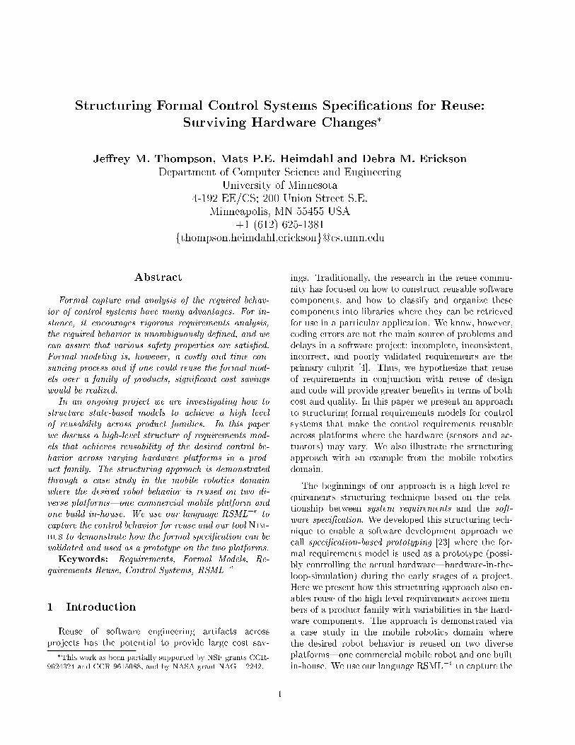
The Normal variable defaults to the startup value.
This allows the spe i� ation to perform various ini-
tialization tasks and he ks before the main behav-
ior takes over. The �rst transition in Figure 5 states
that after two se onds, the spe i� ation will enter the
Cruise Forward state.
The next two transitions govern the way that
6
the Normal state variable an hange from the
Cruise Forward value. If a ollision is dete ted, then
the state variable hanges to the Collision Re over
state. If an obsta le is dete ted, then the spe i� a-
tion will enter the Avoid Obsta le state. Otherwise,
the value of the Normal state variable will remain un-
hanged.
If a ollision or obsta le is dete ted, the ma hine
needs to begin the Cruise Forward behavior when the
aviodan e/re overy a tion has been ompleted. We a -
omplished this in the mobile roboti s spe i� ation by
providing a \done" state in ea h of the sub-behaviors.
This is illustrated by the �fth and sixth transitions in
Figure 5.
Finally, it is also possible to transition from
Avoid Obsta le dire tly to Collision Re over if, for ex-
ample, the robot hits an undete ted obsta le; this ase
is overed by the �nal transition in Figure 5.
Given this de�nition of the REQ relation high-
level behaviors, the de�nitions of the sub-behaviors
an be onstru ted in a similar and straightforward
manner. For example, if the robot hits an obsta-
le, it will attempt to ba k up, turn, and then pro-
eed forward again. This behavior is spe i�ed in the
Robot Re over A tion state variable by having the vari-
able y le though the values Ba kward, Turn, and �-
nally Done.
6 The SOFT relation
When re�ning the spe i� ation from REQ to SOFT,
we sele t the sensors and a tuators that will supply the
software with information about the environment, that
is, we must sele t the hardware and de�ne the IN and
OUT relations for ea h platform. Consequently, we
will also need to de�ne the IN�1 and OUT�1 for ea hplatform. We do not have the spa e to dis uss the IN,
OUT, IN�1, and OUT�1 for every monitored and on-
trolled variable. Instead, we will fo us our dis ussion
on two areas where the Pioneer and the lego-bot pre-
sented illustrative and hallenging di�eren es.
6.1 Obsta le Dete tion|Sonar versus Infrared
As members of the mobile robot produ t family that
we spe i�ed in Se tion 5, both the Pioneer and the lego-
bot have the ability to sense the distan e to obje ts in
their surroundings. Distan e sensors typi ally fun tion
by emitting some sort of signal (for example, a sound
in the ase of sonar) and then measuring the amount
of time between the emission of the signal and its be-
ing re eived ba k at the sensor. Given how fast the
State Variable
Normal
Location: Reactive_Control
Transition: Startup Cruise_Forward
Condition:
TIME > 2 s T
..Failure IN_STATE Ok T
Transition: Cruise_Forward Collision_Recover
Condition:
CollisionDetectedMacro() = TRUE T
..Failure IN_STATE Ok T
Transition: Cruise_Forward Avoid_Obstacle
Condition:
ObstacleDetectedMacro() = TRUE T
CollisionDetectedMacro() = FALSE T
..Failure IN_STATE Ok T
Transition: Collision_Recover Cruise_Forward
Condition:
Prev_Step(..Robot_Recover_Action IN_STATE Done) T
..Failure IN_STATE Ok T
Transition: Avoid_Obstacle Cruise_Forward
Condition:
Prev_Step(..Robot_Avoid_Action IN_STATE Done) T
..Failure IN_STATE Ok T
Transition: Avoid_Obstacle Collision_Recover
Condition:
CollisionDetectedMacro() = TRUE T
..Failure IN_STATE Ok T
Figure 5. The definition of the Normal statevariab le
7
Reactive_ControlOUT_Prime_Eq_Class
MotorStatus
MotorOff
MotorOnMotorPulseStatus
On
Off
SOFT_REQ_Eq_Class
Failure
Ok
Fail
Normal
Startup
Cruise_Forward
Collision_Recover
Robot_Recover_Action
Backward
Turn
Done
Avoid_Obstacle
Obstacle_Distance
Near
Mid
Far
Obstacle_Orientation
On_Right
On_Left
Robot_Avoid_Action
Turn
Forward
Done
Figure 6. The state machine for the lego-bot
signal an travel, the distan e to the losest obje t an
be determined. Although the distan e sensors may be
somewhat similar in their operation, di�erent sensors
provide very di�erent a ura ies and ranges. For ex-
ample, a laser range �nder is far more a urate and has
mu h less noise than the sonar sensors.
The Pioneer uses sonar sensors and the Saphira soft-
ware pa kage to a omplish obsta le dete tion whereas
the lego-bot uses a set of simple infrared range �nders.
This signi� ant di�eren e in the type of sensors as well
as di�eren es in the number and pla ement of the sen-
sors leads to two quite di�erent IN relations. The dif-
feren es of the IN relations ne essitate di�erent IN�1in the omputation of the estimated value of the Range
monitored quantity.
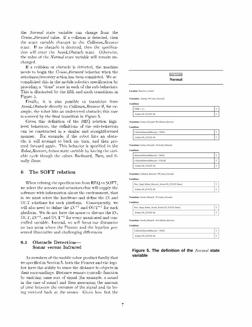
The di�eren e between the SOFT relations for the
two platforms (with respe t to the range to obsta les)
an be en apsulated in a fun tion whi h transforms the
input variables from the range sensors to estimates of
the monitored quantity Range. The omputation for
the Pioneer is pi tured in Figure 7 and for the lego-bot
is in Figure 8. For the Pioneer, the sonar inputs range
from 0 to 700 and must be s aled appropriately to a
number between zero and 100.
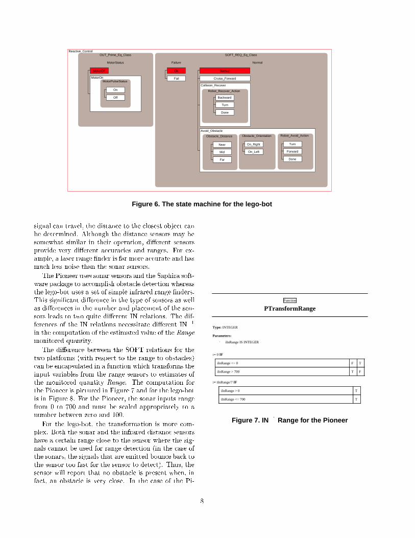
For the lego-bot, the transformation is more om-
plex. Both the sonar and the infrared distan e sensors
have a ertain range lose to the sensor where the sig-
nals annot be used for range dete tion (in the ase of
the sonars, the signals that are emitted boun e ba k to
the sensor too fast for the sensor to dete t). Thus, the
sensor will report that no obsta le is present when, in
fa t, an obsta le is very lose. In the ase of the Pi-
Function
PTransformRange
Type: INTEGER
Parameters:
· iInRange IS INTEGER
:= 0 IF
iInRange <= 0 F T
iInRange > 700 T F
:= iInRange/7 IF
iInRange > 0 T
iInRange <= 700 T
Figure 7. IN�1 Range for the Pioneer
8
Function
LTransformRange
Type: INTEGER
Parameters:
· iInRange IS INTEGER
:= 0 IF
iInRange <= 200 F T
iInRange > 900 T F
:= (900 – iInRange)/8 IF
iInRange > 200 T
iInRange <= 900 T
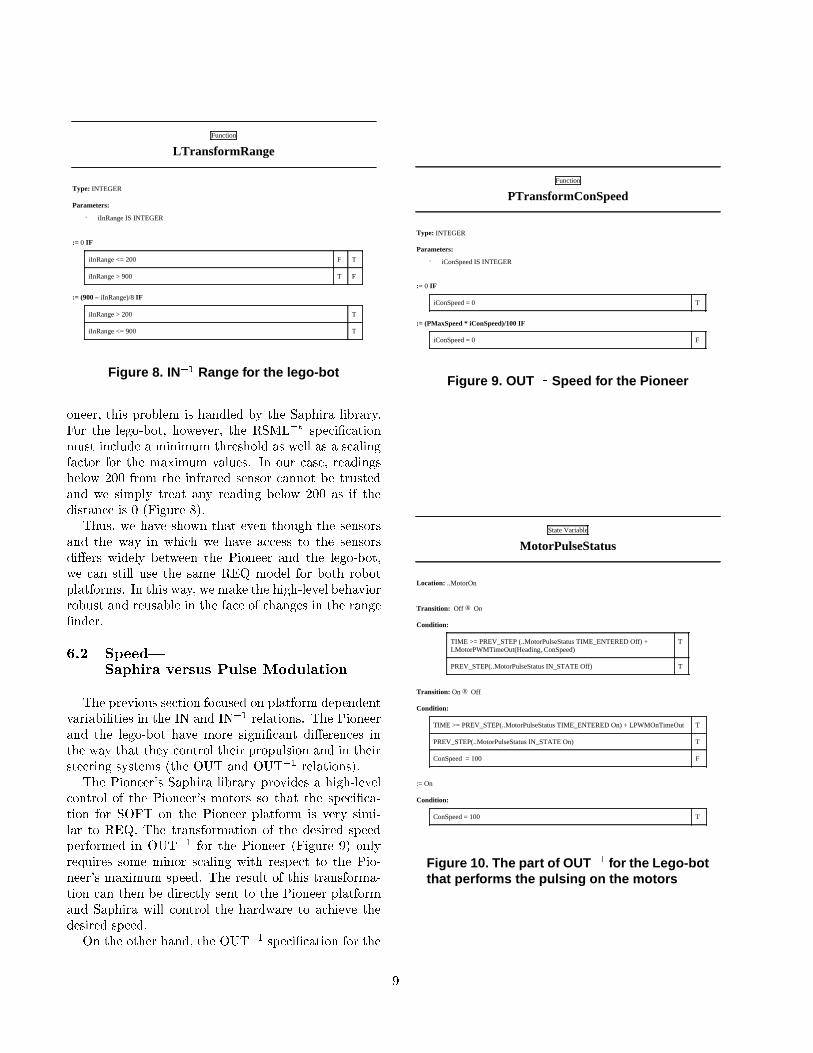
Figure 8. IN�1 Range for the lego-bot
oneer, this problem is handled by the Saphira library.
For the lego-bot, however, the RSML�e spe i� ation
must in lude a minimum threshold as well as a s aling
fa tor for the maximum values. In our ase, readings
below 200 from the infrared sensor annot be trusted
and we simply treat any reading below 200 as if the
distan e is 0 (Figure 8).
Thus, we have shown that even though the sensors
and the way in whi h we have a ess to the sensors
di�ers widely between the Pioneer and the lego-bot,
we an still use the same REQ model for both robot
platforms. In this way, we make the high-level behavior
robust and reusable in the fa e of hanges in the range
�nder.
6.2 Speed|Saphira versus Pulse Modulation
The previous se tion fo used on platform dependent
variabilities in the IN and IN�1 relations. The Pioneerand the lego-bot have more signi� ant di�eren es in
the way that they ontrol their propulsion and in their
steering systems (the OUT and OUT�1 relations).The Pioneer's Saphira library provides a high-level
ontrol of the Pioneer's motors so that the spe i� a-
tion for SOFT on the Pioneer platform is very simi-
lar to REQ. The transformation of the desired speed
performed in OUT�1 for the Pioneer (Figure 9) only
requires some minor s aling with respe t to the Pio-
neer's maximum speed. The result of this transforma-
tion an then be dire tly sent to the Pioneer platform
and Saphira will ontrol the hardware to a hieve the
desired speed.
On the other hand, the OUT�1 spe i� ation for the
Function
PTransformConSpeed
Type: INTEGER
Parameters:
· iConSpeed IS INTEGER
:= 0 IF
iConSpeed = 0 T
:= (PMaxSpeed * iConSpeed)/100 IF
iConSpeed = 0 F
Figure 9. OUT�1 Speed for the Pioneer
State Variable
MotorPulseStatus
Location: ..MotorOn
Transition: Off ® On
Condition:
TIME >= PREV_STEP (..MotorPulseStatus TIME_ENTERED Off) +LMotorPWMTimeOut(Heading, ConSpeed)
T
PREV_STEP(..MotorPulseStatus IN_STATE Off) T
Transition: On ® Off
Condition:
TIME >= PREV_STEP(..MotorPulseStatus TIME_ENTERED On) + LPWMOnTimeOut T
PREV_STEP(..MotorPulseStatus IN_STATE On) T
ConSpeed = 100 F
:= On
Condition:
ConSpeed = 100 T
Figure 10. The par t of OUT�1 for the Lego-botthat perf orms the pulsing on the motor s
9
speed of the lego-bot is signi� antly more omplex.
This is be ause the SOFT relation for the lego-bot
must ontrol the motors dire tly with low-level hard-
ware signals. The speed of the lego-bot is ontrolled
by a te hnique alled pulse width modulation of the DC
motors: the speed of the motors is determined by the
length of time whi h passes between pulses of urrent
applied to the motor. Therefore, the SOFT spe i� a-
tion annot simply output the speed value with some
transformation applied; instead, we must use the om-
puted value for the ontrolled variable Speed to deter-
mine the pulse width for the motors and then output
the pulses a ordingly; the motors will then provide
enough propulsion to move the lego-bot at the desired
speed.
This ontrol strategy ne essitates a more omplex
OUT�1 relation for the desired speed; the OUT�1 re-
lation an no longer be a simple fun tion|in this ase
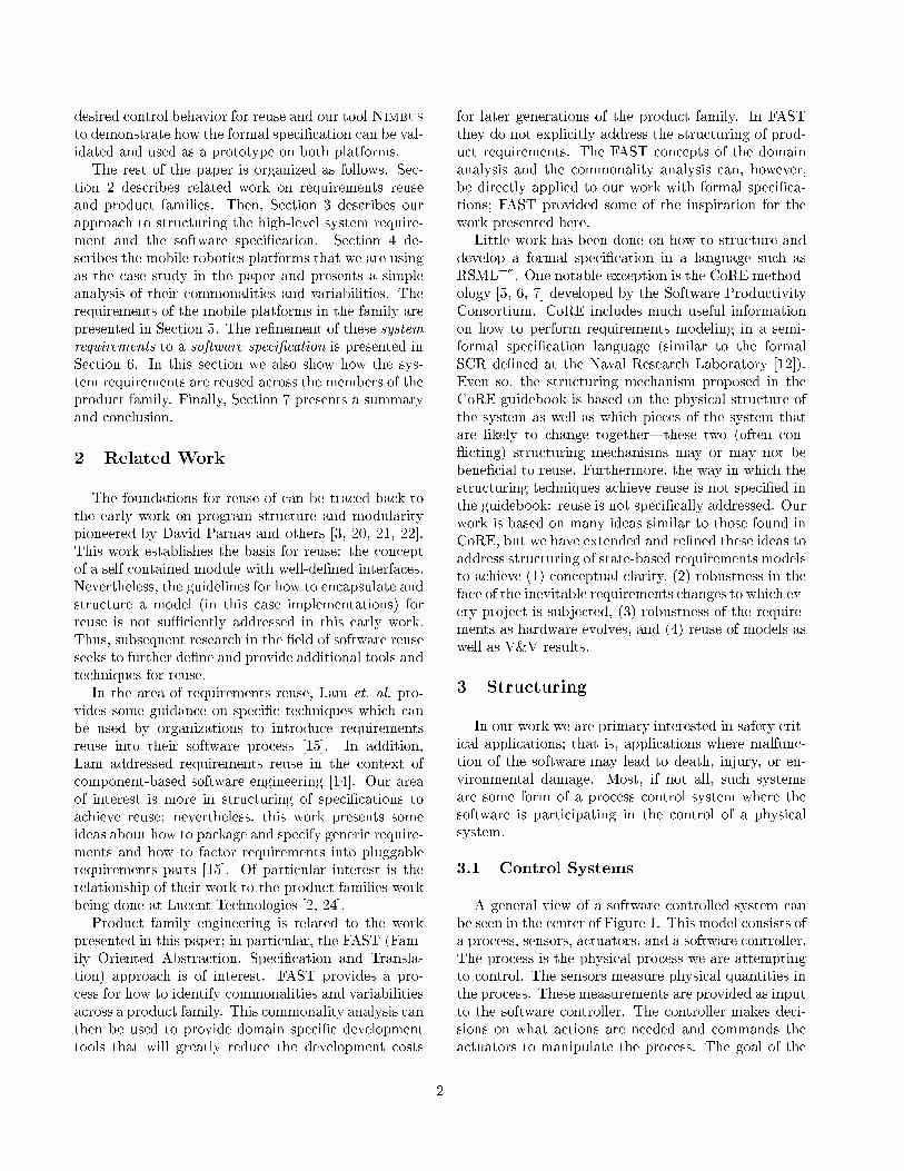
we need to add an additional state ma hine. To model
the pulse modulation we add a state variables to the
SOFT spe i� ation so that the ma hine an output the
required pulses. These additions are shown in Figure 6.
The MotorPulseStatus state variable is the part of the
OUT�1 spe i� ation that determines the pulse width.
Figure 10 shows the de�nition of this state variable.
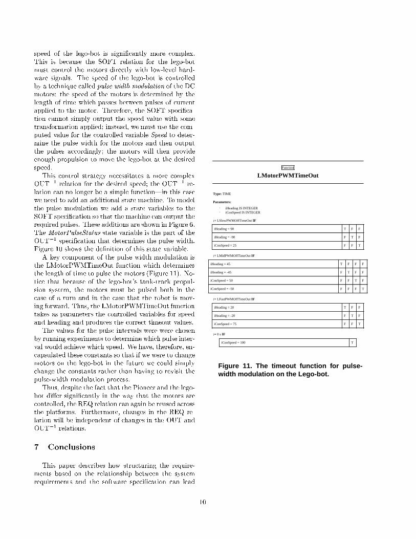
A key omponent of the pulse width modulation is
the LMotorPWMTimeOut fun tion whi h determines
the length of time to pulse the motors (Figure 11). No-
ti e that be ause of the lego-bot's tank-tra k propul-
sion system, the motors must be pulsed both in the
ase of a turn and in the ase that the robot is mov-
ing forward. Thus, the LMotorPWMTimeOut fun tion
takes as parameters the ontrolled variables for speed
and heading and produ es the orre t timeout values.
The values for the pulse intervals were were hosen
by running experiments to determine whi h pulse inter-
val would a hieve whi h speed. We have, therefore, en-
apsulated these onstants so that if we were to hange
motors on the lego-bot in the future we ould simply
hange the onstants rather than having to revisit the
pulse-width modulation pro ess.
Thus, despite the fa t that the Pioneer and the lego-
bot di�er signi� antly in the way that the motors are
ontrolled, the REQ relation an again be reused a ross
the platforms. Furthermore, hanges in the REQ re-
lation will be independent of hanges in the OUT and
OUT�1 relations.7 Con lusions
This paper des ribes how stru turing the require-
ments based on the relationship between the system
requirements and the software spe i� ation an lead
Function
LMotorPWMTimeOut
Type: TIME
Parameters:
· iHeading IS INTEGER· iConSpeed IS INTEGER
:= LSlowPWMOffTimeOut IF
iHeading = 90 T F F
iHeading = -90 F T F
iConSpeed = 25 F F T
:= LMidPWMOffTimeOut IF
iHeading = 45 T F F F
iHeading = -45 F T F F
iConSpeed = 50 F F T F
iConSpeed = -50 F F F T
:= LFastPWMOffTimeOut IF
iHeading = 20 T F F
iHeading = -20 F T F
iConSpeed = 75 F F T
:= 0 s IF
iConSpeed = 100 T
Figure 11. The timeout function for pulse-width modulation on the Lego-bot.
10

to bene�ts in terms of maintainability and reusabil-
ity. Spe i� ally, we des ribe a te hnique for stru turing
high-level requirements for reuse in the fa e of hard-
ware hanges.
From the four variable model for pro ess ontrol sys-
tems, we have des ribed how the REQ relation an be
re�ned to the SOFT relation while maintaining a sep-
aration between the part of SOFT whi h is related to
REQ (SOFTREQ) and the parts of SOFT whi h han-
dle the parti ular sensors and a tuators in the system
design (IN�1 and OUT�1). This allows us to sepa-
rate hanges in the requirements from sensor and a -
tuator hanges and a hieve better maintainability and
reusability.
This te hniques was demonstrated on a ase study
in the mobile roboti s domain using two quite di�erent
robots. One robot is ommer ially produ ed and is
equipped with a ri h ontrol library that provides many
omplex ontrol fun tions, for example, traveling at a
requested speed. The other robot was build in-house
from Lego building blo ks and o�-the-shelf motors and
sensors. This robot is ontrolled ompletely by the
software spe i� ation in RSML�e through our Nimbustoolset.
We demonstrated the usefulness of the stru turing
approa h by reusing the high-level requirements (REQ)
a ross a ( urrently quite small) family of mobile robots.
Nevertheless, there are numerous issues left to address.
In the future, we plan to de�ne more omplex ontrol
behaviors and investigate how individual behaviors (or
operational modes) an be su essfully reused.
Referen es
[1℄ A tivmedia roboti s website. Makers of the Pionner robot.http://www.a tivrobots. om/.
[2℄ Mark A. Ardis and David M. Weiss. De�ning families: The ommonality analysis. In Nineteenth International Confer-en e on Software Engineering (ICSE'97), pages 649{650,1997.
[3℄ K.H. Britton, R.A. Parker, and D.L. Parnas. A pro edurefor designing abstra t interfa es for devi e interfa e mod-ules. In Fifth International Conferen e on Software Engi-neering, 1981.
[4℄ F. P. Brooks. No silver bullet { essen e and a idents ofsoftware engineering. IEEE Computer, 20(4):10{19, April1987.
[5℄ Consortium requirements engineering handbook. Te hni- al Report SPC-92060-CMC, Software Produ tivity Con-sortium, De ember 1993.
[6℄ S. Faulk, J. Bra kett, P. Ward, and J Kirby, Jr. The CoREmethod for real-time requirements. IEEE Software, 9(5),September 1992.
[7℄ Stuart Faulk, Lisa Finneran, James Jr. Kirby, Sudhir Shah,and James Sutton. Experien e applying the CoRE methodto the lo kheed C-103J software requirements. In Pro eed-ings of the Ninth Annual Conferen e on Computer Assur-an e (COMPASS), pages 3{8, 1994.
[8℄ D. Harel. State harts: A visual formalism for omplex sys-tems. S ien e of Computer Programming, pages 231{274,1987.
[9℄ D. Harel, H. La hover, A. Naamad, A. Pnueli, M. Politi,R. Sherman, A. Shtull-Trauring, and M. Trakhtenbrot.Statemate: A working environment for the development of omplex rea tive systems. IEEE Transa tions on SoftwareEngineering, 16(4):403{414, April 1990.
[10℄ D. Harel and A. Pnueli. On the development of rea tive sys-tems. In K.R. Apt, editor, Logi s and Models of Con urrentSystems, pages 477{498. Springer-Verlag, 1985.
[11℄ Mats P. E. Heimdahl and Nan y G. Leveson. Completenessand onsisten y in hierar hi al state-base requirements.IEEE Transa tions on Software Engineering, pages 363{377, June 1996.
[12℄ C. L. Heitmeyer, B. L. Labaw, and D. Kiskis. Consisten y he king of SCR-style requirements spe i� ations. In Pro- eedings of the Se ond IEEE International Symposium onRequirements Engineering, Mar h 1995.
[13℄ Mi hael Ja kson. The world and the ma hine. In Pro- eedings of the 1995 Internation Conferen e on SoftwareEngineering, pages 283{292, 1995.
[14℄ W. Lam. Developing omponent-based tools for require-ments reuse: A pro ess guide. In Eighth InternationalWorkshop on Software Te hnology and Engineering Pra -ti e (STEP'97), pages 473{483, 1997.
[15℄ W. Lam, J.A. M Dermid, and A.J. Vi kers. Ten stepstowards systemati requirements reuse. In Third IEEEInternational Symposium on Requirements Engineering(RE'97), pages 6{15, 1997.
[16℄ Nan y G. Leveson, Mats P.E. Heimdahl, and Jon DamonReese. Designing spe i� ation languages for pro ess ontrolsystems: Lessons learned and steps to the future. In Sev-enth ACM SIGSOFT Symposium on the Foundations onSoftware Engineering, September 1999.
[17℄ N.G. Leveson, M.P.E. Heimdahl, H. Hildreth, and J.D.Reese. Requirements spe i� ation for pro ess- ontrol sys-tems. IEEE Transa tions on Software Engineering, pages684{706, September 1994.
[18℄ Steven P. Miller. Modeling software requirements for em-bedded systems. Te hni al report, Advan ed Te hnologyCenter, Ro kwell Collins, In ., 1999. In Progress.
[19℄ David L. Parnas and Jan Madey. Fun tional do umentationfor omputer systems engineering (volume 2). Te hni alReport CRL 237, M Master University, Hamilton, Ontario,September 1991.
[20℄ D.L. Parnas. On the design and development of pro-gram families. IEEE Transa tions on Software Engineer-ing, 2(1):1{9, 1976.
[21℄ D.L. Parnas. Designing software for ease of extension and ontra tion. In Third International Conferen e on SoftwareEngineering, 1978.
[22℄ D.L. Parnas, P.C. Clements, and D.M. Weiss. The mod-ular stru ture of omplex systems. IEEE Transa tions onSoftware Engineering, 11(3):256{266, 1985.
[23℄ Je�rey M. Thompson, Mats P.E. Heimdahl, and Steven P.Miller. Spe i� ation based prototyping for embedded sys-tems. In Seventh ACM SIGSOFT Symposium on the Foun-dations on Software Engineering, September 1999.
[24℄ David M. Weiss. De�ning families: The ommonality anal-ysis. Te hni al report, Lu ent Te hnologies Bell Laborato-ries, 1000 E. Warrenville Rd, Naperville, IL 60566, 1997.
11