technical reference manual - nwoss.com · system in accordance with the following standards: ......
TRANSCRIPT
QS4 Fire Alarm Control PanelTechnical Reference Manual
P/N 3100186 • Rev 2.0 • 12JUL01
Copyright © 2001. All rights reserved.
Compliance Statement The QS4, hereinafter referred to as the FACP or control panel, whenproperly installed, operates as a Local Protected Premises Fire AlarmSystem in accordance with the following standards:
• NFPA Standard 72, 1999 Edition
• Underwriters Laboratories Standard 864, 7th Edition
• Underwriters Laboratories of Canada Standard ULC S527
In addition, Auxiliary Fire Alarm System operation requires a ReversePolarity Module (RPM). Central Station Fire Alarm System operationrequires a Dialer card (DLD).
Installation in accordance with this manual, applicable codes, and theinstructions of the authority having jurisdiction is mandatory.
Limitation of Liability Edwards Systems Technology (EST) shall not under any circumstancesbe liable for any incidental or consequential damages arising from lossof property or other damages or losses owing to the failure of ESTproducts beyond the cost of repair or replacement of any defectiveproducts. EST reserves the right to make product improvements andchanges to product specifications at any time.
While every precaution was taken during the preparation of thisdocument to ensure its accuracy, EST assumes no responsibility forerrors or omissions.
Fire Alarm SystemLimitations
Automatic fire alarm systems can not guarantee against propertydamage, loss of property, or loss of life. An automatic fire alarm system'sability to provide early warning of a developing fire may be limited for avariety of reasons, but mainly due to improper installation ormaintenance.
The best way to minimize system failures is to perform regularlyscheduled preventive maintenance in accordance with national and localfire codes. All system components and wiring should be tested andmaintained by trained fire alarm system professionals.
FCC Compliance Statement This equipment can generate and radiate radio frequency energy. If thisequipment is not installed in accordance with this manual, it may causeinterference to radio communications. This equipment has been testedand found to comply within the limits for Class A computing devicespursuant to Subpart B of Part 15 of the FCC Rules. These rules aredesigned to provide reasonable protection against such interferencewhen this equipment is operated in a commercial environment.Operation of this equipment is likely to cause interference, in which casethe user at his own expense, will be required to take whatever measuresmay be required to correct the interference.

QS4 Technical Reference Manual i
Content
About this manual • iiiRelated documentation • ivDocument history • vi
Chapter 1 Product description • 1.1System overview • 1.2Component descriptions • 1.3Circuit descriptions • 1.5Controls and indicators • 1.9Controls and indicators behind the flip-down cover • 1.10Controls and indicators on the zone annunciator card • 1.11Interpretation of screen displays • 1.12
Chapter 2 Installation • 2.1Installation do's and don'ts • 2.2Installation checklist • 2.3Two ways to install the cabinet: Surface or semi-flush mount • 2.4How to assemble the panel • 2.6Wiring mains ac and earth ground • 2.7System jumper settings • 2.8System addressing • 2.10Terminal definitions • 2.14Connecting a PT–1S printer • 2.22Installing standby batteries • 2.23
Chapter 3 Operating instructions • 3.1Instructions for the Level 1 operator (public mode access) • 3.2Instructions for the Level 2 operator (emergency mode access) • 3.5Instructions for the Level 3 operator (maintenance mode access) • 3.7Instructions for the Level 4 operator (service mode access) • 3.10QuickReference list • 3.11
Chapter 4 Programming instructions • 4.1Overview • 4.2QuickStart setup instructions • 4.4Customizing the system configuration • 4.13Setting up an Output Group • 4.21Setting up a Zone • 4.26
Chapter 5 Standard applications • 5.1Notification appliance circuits • 5.2Initiating device circuits • 5.5Coded alarm signaling • 5.8Remote station protective signaling system • 5.10Auxiliary protective signaling • 5.12
Chapter 6 Maintenance instructions • 6.1Pseudo point definitions • 6.2Maintenance tasks • 6.6

Content
ii QS4 Technical Reference Manual
Appendix A System calculations • A.1Notification appliance circuit maximum wire length calculation • A.2Signature loop maximum wire length calculations • A.3Battery calculation worksheet • A.8
Appendix B Barcode library • B.1
Appendix C SIGA-REL programming • C.1Application block diagram • C.2Programming instructions • C.3

Content
QS4 Technical Reference Manual iii
About this manual
Organization This manual provides information on how to properly install, wire, andmaintain the FACP and related components, and is organized asfollows:
Chapter 1 provides a detailed description of the fire alarm control paneland its operation.
Chapter 2 provides instructions for installing the fire alarm controlpanel.
Chapter 3 provides instructions for operating the control panel.
Chapter 4 provides instructions for programming the fire alarm systemfrom the front panel.
Chapter 5 provides simplified wiring schematics for standardapplications.
Chapter 6 provides instructions for maintaining the system.
Appendix A provides worksheets for calculating maximum wire lengthsfor notification and Signature circuits, and for sizing standby batteries.
Appendix B provides a set of bar codes that you can use to enter textfor location messages.
Appendix C provides information on how to program the SIGA–RELusing the QS–CU (QuickStart Configuration Utility).
Safety information Important safety admonishments are used throughout this manual towarn of possible hazards to persons or equipment.
WARNING: Warnings are used to indicate the presence of a hazardwhich will or may cause personal injury or death, or loss of service ifsafety instructions are not followed or if the hazard is not avoided.
Caution: Cautions are used to indicate the presence of a hazard whichwill or may cause damage to the equipment if safety instructions are notfollowed or if the hazard is not avoided.

Content
iv QS4 Technical Reference Manual
Related documentation
National Fire Protection Association1 Batterymarch ParkP.O. Box 9101Quincy, MA 02269-9101
NFPA 70 National Electric Code
NFPA 72 National Fire Alarm Code
NFPA 11 Low-Expansion Foam Systems
NFPA 11A Medium- and High-Expansion Foam Systems
NFPA 12 Carbon Dioxide Extinguishing Systems
NFPA 13 Sprinkler Systems
NFPA 15 Water Spray Fixed Systems for Fire Protection
NFPA 16 Deluge Foam-Water Sprinkler and Foam-Water SpraySystems
NFPA 17Dry Chemical Extinguishing Systems
Underwriters Laboratories, Inc.333 Pfingsten RoadNorthbrook, IL 60062-2096
UL 38 Manually Actuated Signaling Boxes
UL 217 Smoke Detectors, Single & Multiple Station
UL 228 Door Closers/Holders for Fire Protective SignalingSystems
UL 268 Smoke Detectors for Fire Protective Signaling Systems
UL 268A Smoke Detectors for Duct Applications
UL 346 Waterflow Indicators for Fire Protective SignalingSystems
UL 464 Audible Signaling Appliances
UL 521 Heat Detectors for Fire Protective Signaling Systems
UL 864 Standard for Control Units for Fire Protective SignalingSystems
UL 1481 Power Supplies for Fire Protective Signaling Systems
UL 1638 Visual Signaling Appliances
UL 1971 Visual Signaling Appliances
Underwriters Laboratories ofCanada7 Crouse RoadScarborough, ONCanada M1R 3A9
Canadian Electrical Code Part 1
ULC S527 Standard for Control Units for Fire Alarm Systems
ULC S524 Standard for the Installation of Fire Alarm Systems
ULC S536 Standard for the Inspection and Testing of FireAlarm Systems
ULC S537 Standard for the Verification of Fire Alarm Systems
ULC ORD–C693–1994 Central Station Fire Protective SignalingSystem and Services
Content
QS4 Technical Reference Manual v
Edwards Systems Technology6411 Parkland DriveSarasota, FL 34243
2–CTM City Tie Module Installation Sheet (P/N 270496)
CDR–3 Bell Coder Installation Sheet (P/N 3100023)
DLD Dual Inline Dialer Installation Sheet (P/N 3100187)
PS6 Power Supply Card Installation Sheet (P/N 3100201)
QSA–1(X), QSA–2(X) Remote Annunciator Cabinet InstallationSheet (P/N 3100295)
QS–CPU(X) CPU/Display Unit Installation Sheet (P/N 3100276)
SL30, SL30–1 LED/Switch Card Installation Sheet (P/N3100193)
SLIC Signature Intelligent Controller Card Installation Sheet(P/N 3100192)
RS485 (NT–A) Card and QS–232 UART Module InstallationSheet (P/N 3100191)
ZA8–2 Class A Zone Card Installation Sheet (P/N 3100189)
ZB16–4 Class B Zone Card Installation Sheet (P/N 3100188)
ZR8 Relay Card Installation Sheet (P/N 3100190)
SIGA–APS Auxiliary Power Supply Installation Sheet (P/N387342)
Signature Series Intelligent Smoke and Heat DetectorsApplications Bulletin (P/N 270145)
Signature Series Component Installation Manual (P/N 270497)
EST Strobe Applications Guide (P/N 85000-0049)
QuickStart Online Help Utility (P/N 7350047)
QuickStart ULI and ULC Compatibility Lists (P/N 3100335)
Network Hardware Technical Reference (P/N 250100)

Content
vi QS4 Technical Reference Manual
Document history
Date Revision Description of changes
24JUN01 1.0 Original release.
12JUL01 2.0 Corrections and additions on pp 2.12, 2.24, 3.9, 4.4, 4.8, 4.10, 4.19,A.3.
QS4 Technical Reference Manual 1.1
Chapter 1 Product description
SummaryThis chapter provides a detailed description of the fire alarm controlpanel and its operation.
ContentSystem overview • 1.2Component descriptions • 1.3Circuit descriptions • 1.5Controls and indicators • 1.9Controls and indicators behind the flip-down cover • 1.10Controls and indicators on the zone annunciator card • 1.11Interpretation of screen displays • 1.12

Product description
1.2 QS4 Technical Reference Manual
System overviewSystem hardware capabilitiesHardware capabilities vary depending on cabinetsize and option card configuration, but generally:
• Up to four Class A or Class B Signaturesignaling line circuits that support up to 250single-address Signature devices each
• Up to 40 Class A or 48 Class B initiating devicecircuits (IDC). Combination systems can notexceed 40 IDC circuits total
• Up to 16 Class A or 20 Class B notificationappliance
• Up to two 30-zone displays
• Up to 96 dry-contact relay
• 4.5 amps of 24 Vdc power for externalnotification appliances
• Battery charger capable of charging batteriesrated up to 40 Ah. Maximum battery size forULC applications is 30 Ah
• Up to eight, fully-supervised, mirrored orcustomized remote annunciators
Minimum system requirementsA Local Protected Premises Fire Alarm Systemrequires only the FACP (CPU, PS6, andenclosure) with at least one SLIC, ZB16–4, orZA8–2 card programmed with at least one audibleoutput circuit and one alarm input circuit.
In addition to the hardware requirements of aLocal system:
• Add a 2–CTM City Tie Module for an AuxiliaryFire Alarm System
• Add a DLD Dual Line Dialer Card or RPMReverse Polarity Module for a RemoteSupervising Station Fire Alarm System
• Add a DLD Dual Line Dialer Card or RPMReverse Polarity Module for a Central StationFire Alarm System
• Add a SIGA–REL for Releasing Device Service
Normal operating mode descriptionThe panel operates in normal mode in theabsence of any alarm, supervisory, trouble, and
monitor events. In normal mode, the control panelmonitors the system for any events.
Off-normal operating mode descriptionThe panel operates in off-normal mode any timethere is an event introduced into the system.When this happens, the CPU:
• Changes the contact positions on theappropriate common relays
• Activates all common alarm outputs (alarmevents only)
• Turns on the panel buzzer
• Executes the appropriate programmed outputresponse for the input that signaled the event
• Sends a record of the event to the appropriatedisplay queue and out the serial port
If there is no operator in attendance, the paneldisplays the content of the highest priority displayqueue containing a record.
If there is an operator in attendance, the paneldisplays the content of the current display queueregardless of any new events introduced into thesystem.
Failsafe operating mode descriptionThe panel operates in failsafe mode when theCPU loses the ability to communicate with the PS6and JP1 on the PS6 is in the ON position. Whenthis happens, the power supply:
• Closes the common trouble relay contacts
• Instructs the dialer to send the default troublemessage
• Monitors the system for any alarm events
If an alarm event occurs, the power supply:
• Changes the contact positions on the commonalarm relay
• Turns on all conventional common alarmoutputs. Signature common alarm outputs arenot affected.
• Instructs the dialer to send the default alarmmessage
Product description
QS4 Technical Reference Manual 1.3
Component descriptions
1 2 3 6A 5 6B 7 84
9
10
J5
13
JP1
J2
J7
J8
JP1 CONFIGURATIONPIN 1 & 2 = MODEM PWR
PIN 2 & 3 = RTS
J6
14 13 111215
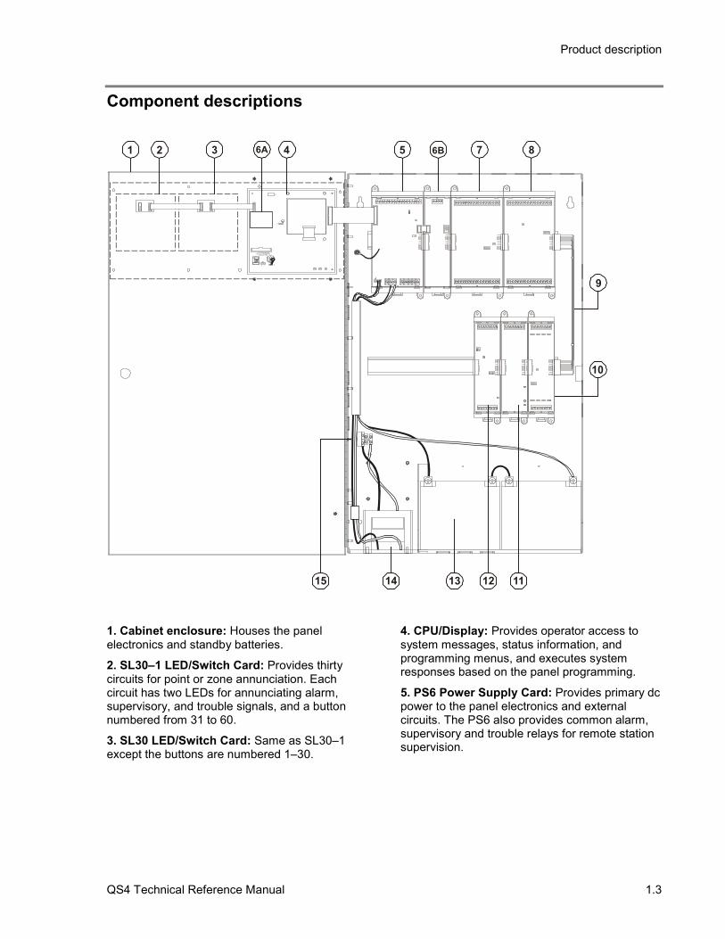
1. Cabinet enclosure: Houses the panelelectronics and standby batteries.
2. SL30–1 LED/Switch Card: Provides thirtycircuits for point or zone annunciation. Eachcircuit has two LEDs for annunciating alarm,supervisory, and trouble signals, and a buttonnumbered from 31 to 60.
3. SL30 LED/Switch Card: Same as SL30–1except the buttons are numbered 1–30.
4. CPU/Display: Provides operator access tosystem messages, status information, andprogramming menus, and executes systemresponses based on the panel programming.
5. PS6 Power Supply Card: Provides primary dcpower to the panel electronics and externalcircuits. The PS6 also provides common alarm,supervisory and trouble relays for remote stationsupervision.

Product description
1.4 QS4 Technical Reference Manual
6. RS485 (NT–A) Class A Card: The NT–Acomprises the RS485 card and QS–232 UARTmodule. Together these provide an additionalRS–232 channel to allow Class A communicationbetween the control panel and other remoteannunciator panels. Control panels requireinstallation of both cards while remoteannunciator panels only require installation of aQS–232 card and only then if you want toconnect a printer or service computer.
7. ZA8–2 Class A Conventional Zone Card:Provides six dedicated Class A initiating devicecircuits (IDCs) for connecting two-wire smokedetectors and dry-contact initiating devices. TheZA8–2 also provides two circuits that you canconfigure as IDCs or as 24 Vdc notificationappliance circuits (NACs).
8. ZB16–4 Class B Conventional Zone Card:Provides twelve dedicated Class B initiatingdevice circuits (IDCs) for connecting two-wiresmoke detectors and dry-contact initiatingdevices. The ZB16–4 also provides four circuitsthat you can configure as IDCs or as Class B 24Vdc notification appliance circuits (NACs).
9. QS–Cable12 Expansion Cable: Extends theCPU data and power bus to circuit cards installedon the lower DIN rail in the 12-option cabinet.
10. ZR8 Relay Card: Provides eight dry-contactrelays. You can configure each relay fornormally-open or normally-closed operation.
11. DLD Dual Line Dialer Card: Provides twotelephone line connections for sending systemmessages to a compatible Digital AlarmCommunicator Receiver.
12. SLIC Signature Loop Intelligent ControllerCard: Provides one Class A or Class B signalingline circuit (loop) for connecting Signature seriesdetectors and modules. The SLIC also providestwo Class A or Class B notification appliancecircuits (NACs) for connecting polarized 24 Vdcnotification appliances (horns, strobes).
13. Standby batteries: Provides dc power to thepanel electronics in the absence of ac power.
14. Transformer: Changes the mains ac supplyvoltage for the power supply card.
15. AC wiring block and fuse holder: Providesconnections for mains ac (primary power) and 5Afuse.
Product description
QS4 Technical Reference Manual 1.5
Circuit descriptions
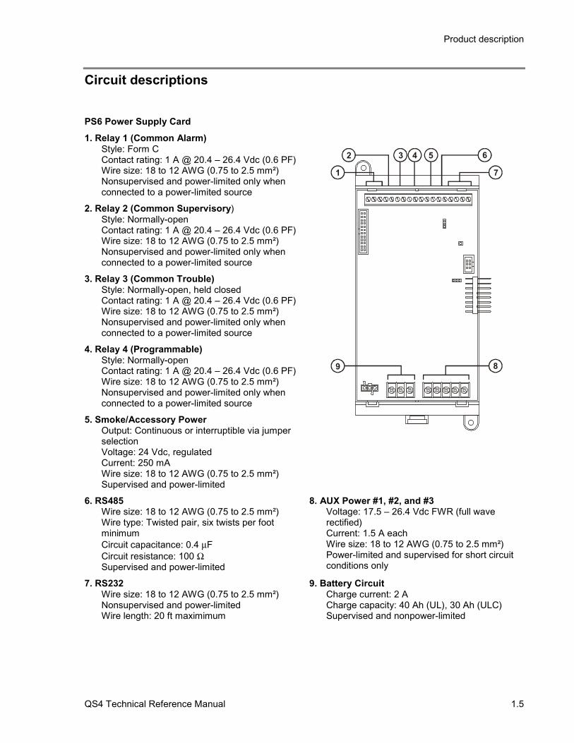
PS6 Power Supply Card1. Relay 1 (Common Alarm)
Style: Form CContact rating: 1 A @ 20.4 – 26.4 Vdc (0.6 PF)Wire size: 18 to 12 AWG (0.75 to 2.5 mm²)Nonsupervised and power-limited only whenconnected to a power-limited source
2. Relay 2 (Common Supervisory)Style: Normally-openContact rating: 1 A @ 20.4 – 26.4 Vdc (0.6 PF)Wire size: 18 to 12 AWG (0.75 to 2.5 mm²)Nonsupervised and power-limited only whenconnected to a power-limited source
3. Relay 3 (Common Trouble)Style: Normally-open, held closedContact rating: 1 A @ 20.4 – 26.4 Vdc (0.6 PF)Wire size: 18 to 12 AWG (0.75 to 2.5 mm²)Nonsupervised and power-limited only whenconnected to a power-limited source
4. Relay 4 (Programmable)Style: Normally-openContact rating: 1 A @ 20.4 – 26.4 Vdc (0.6 PF)Wire size: 18 to 12 AWG (0.75 to 2.5 mm²)Nonsupervised and power-limited only whenconnected to a power-limited source
5. Smoke/Accessory PowerOutput: Continuous or interruptible via jumperselectionVoltage: 24 Vdc, regulatedCurrent: 250 mAWire size: 18 to 12 AWG (0.75 to 2.5 mm²)Supervised and power-limited
71
2 6
9 8
53 4
6. RS485Wire size: 18 to 12 AWG (0.75 to 2.5 mm²)Wire type: Twisted pair, six twists per footminimumCircuit capacitance: 0.4 µFCircuit resistance: 100 ΩSupervised and power-limited
8. AUX Power #1, #2, and #3Voltage: 17.5 – 26.4 Vdc FWR (full waverectified)Current: 1.5 A eachWire size: 18 to 12 AWG (0.75 to 2.5 mm²)Power-limited and supervised for short circuitconditions only
7. RS232Wire size: 18 to 12 AWG (0.75 to 2.5 mm²)Nonsupervised and power-limitedWire length: 20 ft maximimum
9. Battery CircuitCharge current: 2 ACharge capacity: 40 Ah (UL), 30 Ah (ULC)Supervised and nonpower-limited

Product description
1.6 QS4 Technical Reference Manual
SLIC Signature Loop Intelligent Controller Card circuits
1. NAC #1Configuration: Class B or Class AOutput voltage: 24 Vdc, nominalOutput current: 2.0 A @ 24 VdcWire size: 18 to 12 AWG (0.75 to 2.5 mm2)End of line resistor: 10 kΩ, 1/2WSupervised and power-limited
2. NAC #2Configuration: Class B or Class AOutput voltage: 24 Vdc, nominalOutput current: 1.0 A @ 24 VdcWire size: 18 to 12 AWG (0.75 to 2.5 mm2)End of line resistor: 10 kΩ, 1/2WSupervised and power-limited
3. Signature LoopConfiguration: Class B (Style 4) or Class A (Style 6)Capacity: 125 Signature detectors, 125 Signature single-addressmodulesWire size: 18 to 12 AWG (0.75 to 2.5 mm2)Circuit resistance: 65 ΩCircuit capacitance: 0.3 µFSupervised and power-limited
4. NAC Riser In/OutVoltage: 24 Vdc, nominalWire size: 18 to 12 AWG (0.75 to 2.5 mm2)
1 2
4 3
ZR8 Relay Card circuits
1. Dry-contact relays R1 – R4Outputs: Normally-open or normally-closed contacts via jumperselectionContact rating: 24 Vdc @ 1.0 AWire size: 18 to 12 AWG (0.75 to 2.5 mm2)Nonsupervised, and power-limited only when connected to apower-limited source
2. Dry-contact relays R5 – R8Outputs: Normally-open or normally-closed contacts via jumperselectionContact rating: 24 Vdc @ 1.0 AWire size: 18 to 12 AWG (0.75 to 2.5 mm2)Nonsupervised, and power-limited only when connected to apower-limited source
1
2
Product description
QS4 Technical Reference Manual 1.7
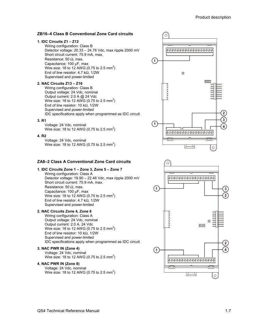
ZB16–4 Class B Conventional Zone Card circuits
1. IDC Circuits Z1 – Z12Wiring configuration: Class BDetector voltage: 20.33 – 24.76 Vdc, max ripple 2000 mVShort circuit current: 75.9 mA, max.Resistance: 50 Ω, max.Capacitance: 100 µF, maxWire size: 18 to 12 AWG (0.75 to 2.5 mm2)End of line resistor: 4.7 kΩ, 1/2WSupervised and power-limited
2. NAC Circuits Z13 – Z16Wiring configuration: Class BOutput voltage: 24 Vdc, nominalOutput current: 2.0 A @ 24 VdcWire size: 18 to 12 AWG (0.75 to 2.5 mm2)End of line resistor: 10 kΩ, 1/2WSupervised and power-limitedIDC specifications apply when programmed as IDC circuit
3. R1Voltage: 24 Vdc, nominalWire size: 18 to 12 AWG (0.75 to 2.5 mm2)
4. R2Voltage: 24 Vdc, nominalWire size: 18 to 12 AWG (0.75 to 2.5 mm2)
13
4
2
1
ZA8–2 Class A Conventional Zone Card circuits
1. IDC Circuits Zone 1 – Zone 3, Zone 5 – Zone 7Wiring configuration: Class ADetector voltage: 19.90 – 22.46 Vdc, max ripple 2000 mVShort circuit current: 75.9 mA, max.Resistance: 50 Ω, max.Capacitance: 100 µF, maxWire size: 18 to 12 AWG (0.75 to 2.5 mm2)End of line resistor: 4.7 kΩ, 1/2WSupervised and power-limited
2. NAC Circuits Zone 4, Zone 8Wiring configuration: Class AOutput voltage: 24 Vdc, nominalOutput current: 2.0 A, 24 VdcWire size: 18 to 12 AWG (0.75 to 2.5 mm2)End of line resistor: 10 kΩ, 1/2WSupervised and power-limitedIDC specifications apply when programmed as IDC circuit
3. NAC PWR IN (Zone 4)Voltage: 24 Vdc, nominalWire size: 18 to 12 AWG (0.75 to 2.5 mm2)
4. NAC PWR IN (Zone 8)Voltage: 24 Vdc, nominalWire size: 18 to 12 AWG (0.75 to 2.5 mm2)
1
23
1 42

Product description
1.8 QS4 Technical Reference Manual
DLD Dual Line Dialer Card circuits
1. Line #1Supervised and nonpower-limited
2. Line #2Supervised and nonpower-limited 1 2
RS485 (NT–A) Class A Card circuits
1. Secondary RS485 channelWire size: 18 to 12 AWG (0.75 to 2.5 mm2)Supervised and power-limited
2. Primary RS485 channelWire size: 18 to 12 AWG (0.75 to 2.5 mm2)Supervised and power-limited
Note: JP1 installed for ground fault detection on RS485 circuits.
1 2
Product description
QS4 Technical Reference Manual 1.9
Controls and indicators
1 2 3 4
1
6 7 8 9 0
2
3
5
4
5
6
7
8
9
10
11
12
13
14
15
16
17
18
19
20
21
22
23
24
25
26
27
28
29
30
12
2 3 4 5 61 7 8 9
1
2
3
4
5
6
7
8
9
10
11
12
13
14
15
16
17
18
19
20
21
22
23
24
25
26
27
28
29
30
11 10
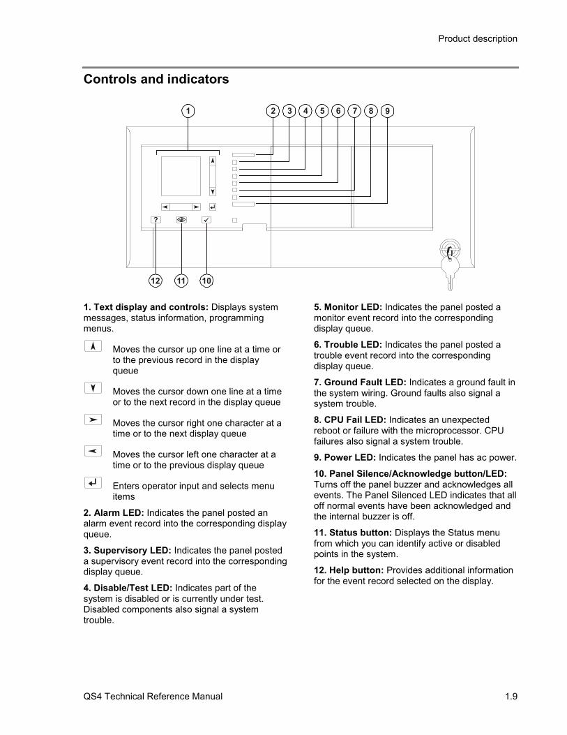
1. Text display and controls: Displays systemmessages, status information, programmingmenus.
Moves the cursor up one line at a time orto the previous record in the displayqueue
Moves the cursor down one line at a timeor to the next record in the display queue
Moves the cursor right one character at atime or to the next display queue
Moves the cursor left one character at atime or to the previous display queue
Enters operator input and selects menuitems
2. Alarm LED: Indicates the panel posted analarm event record into the corresponding displayqueue.
3. Supervisory LED: Indicates the panel posteda supervisory event record into the correspondingdisplay queue.
4. Disable/Test LED: Indicates part of thesystem is disabled or is currently under test.Disabled components also signal a systemtrouble.
5. Monitor LED: Indicates the panel posted amonitor event record into the correspondingdisplay queue.
6. Trouble LED: Indicates the panel posted atrouble event record into the correspondingdisplay queue.
7. Ground Fault LED: Indicates a ground fault inthe system wiring. Ground faults also signal asystem trouble.
8. CPU Fail LED: Indicates an unexpectedreboot or failure with the microprocessor. CPUfailures also signal a system trouble.
9. Power LED: Indicates the panel has ac power.
10. Panel Silence/Acknowledge button/LED:Turns off the panel buzzer and acknowledges allevents. The Panel Silenced LED indicates that alloff normal events have been acknowledged andthe internal buzzer is off.
11. Status button: Displays the Status menufrom which you can identify active or disabledpoints in the system.
12. Help button: Provides additional informationfor the event record selected on the display.
Product description
1.10 QS4 Technical Reference Manual
Controls and indicators behind the flip-down cover
1 2 3 4
1
6 7 8 9 0
2
3
5
4
5
6
7
8
9
10
11
12
13
14
15
16
17
18
19
20
21
22
23
24
25
26
27
28
29
30
1
2
3
4
5
6
7
8
9
10
11
12
13
14
15
16
17
18
19
20
21
22
23
24
25
26
27
28
29
30
3
6
9
5
8
4
7
2 1
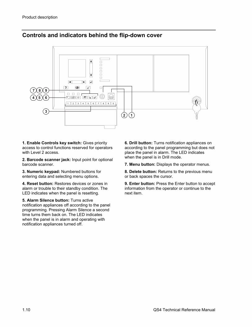
1. Enable Controls key switch: Gives priorityaccess to control functions reserved for operatorswith Level 2 access.
2. Barcode scanner jack: Input point for optionalbarcode scanner.
3. Numeric keypad: Numbered buttons forentering data and selecting menu options.
4. Reset button: Restores devices or zones inalarm or trouble to their standby condition. TheLED indicates when the panel is resetting.
5. Alarm Silence button: Turns activenotification appliances off according to the panelprogramming. Pressing Alarm Silence a secondtime turns them back on. The LED indicateswhen the panel is in alarm and operating withnotification appliances turned off.
6. Drill button: Turns notification appliances onaccording to the panel programming but does notplace the panel in alarm. The LED indicateswhen the panel is in Drill mode.
7. Menu button: Displays the operator menus.
8. Delete button: Returns to the previous menuor back spaces the cursor.
9. Enter button: Press the Enter button to acceptinformation from the operator or continue to thenext item.

Product description
QS4 Technical Reference Manual 1.11
Controls and indicators on the zone annunciator card
1
2
3
4
5
6
7
8
9
10
11
12
13
14
15
16
17
18
19
20
21
22
23
24
25
26
27
28
29
30
21 3
1. Zone display button: Displays an eventrecord for each device in the corresponding zonethat signaled an alarm.
2. Zone active LED: Indicates a device in thecorresponding zone signaled an alarm condition.
3. Zone trouble LED: Indicates a device orwiring fault in the corresponding Zone.
Note: ULC requires that every fire panel have thecapability to visually display system status bymeans of specific indicators for each zone. Allstatus changes must clearly indicate that theinformation is an Alarm (ALM), Supervisory(SUP), Trouble (TBL), or Monitor (MON).

Product description
1.12 QS4 Technical Reference Manual
Interpretation of screen displays
HH:MM:SS MM/DD
System Normal
Project Name
Alarm History:nnnn
This is what the panel display looks like when there are no eventrecords posted in a display queue.
HH:MM:SS is the current time in hours, minutes, and seconds
MM/DD is the current month and date
nnnn is the number times the panel went into alarm since beingplaced into service
HH:MM:SSAxxx Dxxx
nnn event nameCustom message 1Custom message 2
nnn event nameCustom message 1Custom message 2
ALM SUP TRBL MONaaa sss ttt mmm
This is what the panel display looks like when there are eventrecords posted in a display queue.
HH:MM:SS is the current time in hours, minutes, and seconds
Axxx is the current number of active points
Dxxx is the current number of disabled points
These items comprise the event record:
nnn is the posting sequence number (001 = first, 002 = second, andso on)
event name is the event produced when the device changed states.Refer to Table 1-1.
P:pp C:cc D:ddd is the address of the device that signaled theevent (P = panel number, C = card number, D = device number)
The event record may also include a custom message that typicallyindicates the location of the device, depending on the panelprogramming.
These items indicate the content of the display queues:
aaa is the number of alarm event records (highest priority)
sss is the number of supervisory event records
ttt is the number of trouble event records
mmm is the number of monitor event records (lowest priority)
Product description
QS4 Technical Reference Manual 1.13
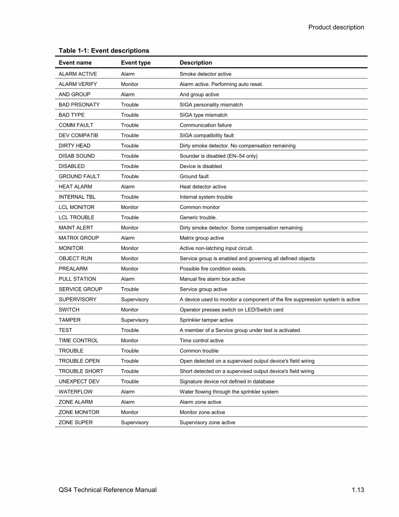
Table 1-1: Event descriptions
Event name Event type Description
ALARM ACTIVE Alarm Smoke detector active
ALARM VERIFY Monitor Alarm active. Performing auto reset.
AND GROUP Alarm And group active
BAD PRSONATY Trouble SIGA personality mismatch
BAD TYPE Trouble SIGA type mismatch
COMM FAULT Trouble Communication failure
DEV COMPATIB Trouble SIGA compatibility fault
DIRTY HEAD Trouble Dirty smoke detector. No compensation remaining
DISAB SOUND Trouble Sounder is disabled (EN–54 only)
DISABLED Trouble Device is disabled
GROUND FAULT Trouble Ground fault
HEAT ALARM Alarm Heat detector active
INTERNAL TBL Trouble Internal system trouble
LCL MONITOR Monitor Common monitor
LCL TROUBLE Trouble Generic trouble.
MAINT ALERT Monitor Dirty smoke detector. Some compensation remaining
MATRIX GROUP Alarm Matrix group active
MONITOR Monitor Active non-latching input circuit.
OBJECT RUN Monitor Service group is enabled and governing all defined objects
PREALARM Monitor Possible fire condition exists.
PULL STATION Alarm Manual fire alarm box active
SERVICE GROUP Trouble Service group active
SUPERVISORY Supervisory A device used to monitor a component of the fire suppression system is active
SWITCH Monitor Operator presses switch on LED/Switch card
TAMPER Supervisory Sprinkler tamper active
TEST Trouble A member of a Service group under test is activated
TIME CONTROL Monitor Time control active
TROUBLE Trouble Common trouble
TROUBLE OPEN Trouble Open detected on a supervised output device's field wiring
TROUBLE SHORT Trouble Short detected on a supervised output device's field wiring
UNEXPECT DEV Trouble Signature device not defined in database
WATERFLOW Alarm Water flowing through the sprinkler system
ZONE ALARM Alarm Alarm zone active
ZONE MONITOR Monitor Monitor zone active
ZONE SUPER Supervisory Supervisory zone active

Product description
1.14 QS4 Technical Reference Manual
QS4 Technical Reference Manual 3.1
Chapter 3 Operating instructions
SummaryThis chapter provides instructions for operating the control panel.
ContentInstructions for the Level 1 operator (public mode access) • 3.2Instructions for the Level 2 operator (emergency mode access) • 3.5Instructions for the Level 3 operator (maintenance mode access) • 3.7Instructions for the Level 4 operator (service mode access) • 3.10QuickReference list • 3.11
Operating instructions
3.2 QS4 Technical Reference Manual
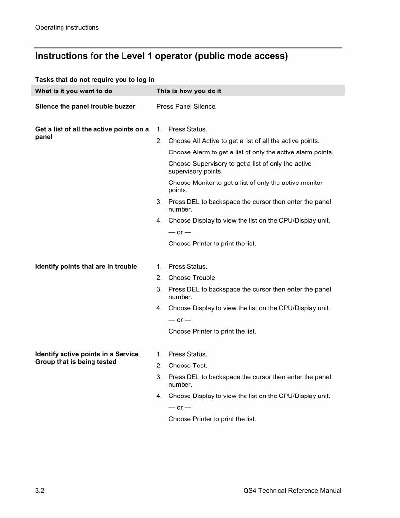
Instructions for the Level 1 operator (public mode access)
Tasks that do not require you to log inWhat is it you want to do This is how you do it
Silence the panel trouble buzzer Press Panel Silence.
Get a list of all the active points on apanel
1. Press Status.
2. Choose All Active to get a list of all the active points.
Choose Alarm to get a list of only the active alarm points.
Choose Supervisory to get a list of only the activesupervisory points.
Choose Monitor to get a list of only the active monitorpoints.
3. Press DEL to backspace the cursor then enter the panelnumber.
4. Choose Display to view the list on the CPU/Display unit.
— or —
Choose Printer to print the list.
Identify points that are in trouble 1. Press Status.
2. Choose Trouble
3. Press DEL to backspace the cursor then enter the panelnumber.
4. Choose Display to view the list on the CPU/Display unit.
— or —
Choose Printer to print the list.
Identify active points in a ServiceGroup that is being tested
1. Press Status.
2. Choose Test.
3. Press DEL to backspace the cursor then enter the panelnumber.
4. Choose Display to view the list on the CPU/Display unit.
— or —
Choose Printer to print the list.

Operating instructions
QS4 Technical Reference Manual 3.3
Tasks that do not require you to log inWhat is it you want to do This is how you do it
Identify points that are disabled 1. Press Status.
2. Choose Disabled Pts.
3. Press DEL to backspace the cursor then enter the panelnumber.
4. Choose Display to view the list on the CPU/Display unit.
— or —
Choose Printer to print the list.
Identify output devices that areturned on
1. Press Status.
2. Choose Outputs
3. Press DEL to backspace the cursor then enter the panelnumber.
4. Choose Display to view the list on the CPU/Display unit.
— or —
Choose Printer to print the list.
Verify power supply voltage levels 1. Press Status.
2. Choose Internal
3. Press Enter.
4. Choose Display to view the list on the CPU/Display unit.
— or —
Choose Printer to print the list.
Get a list of smoke detectors thatrequire servicing (DIRTY attributegreater than 80%)
1. Press Menu.
2. Choose Reports > Maintenance > Dirty>80%.
3 Enter the panel number.
4. Choose Display to view the list on the CPU/Display unit.
— or —
Choose Printer to print the list.

Operating instructions
3.4 QS4 Technical Reference Manual
Tasks that do not require you to log inWhat is it you want to do This is how you do it
Get a list of smoke detectors thatmay require servicing (DIRTYattribute greater than 20%)
1. Press Menu.
2. Choose Reports > Maintenance > Dirty>20%.
3 Enter the panel number.
4. Choose Display to view the list on the CPU/Display unit.
— or —
Choose Printer to print the list.
Get the attributes for a single smokedetector
1. Press Menu.
2. Choose Reports > Maintenance > Single Device.
3. Enter the panel number.
4. Choose Display to view the list on the CPU/Display unit.
— or —
Choose Printer to print the list.
Get the attributes for every smokedetector on a single SLIC
1. Press Menu.
2. Choose Reports > Maintenance > Card Devices.
3 Enter the panel number.
4. Choose Display to view the list on the CPU/Display unit.
— or —
Choose Printer to print the list.
Perform a lamp test 1. Press Menu.
2. Choose Test > Lamp Test.
Operating instructions
QS4 Technical Reference Manual 3.5
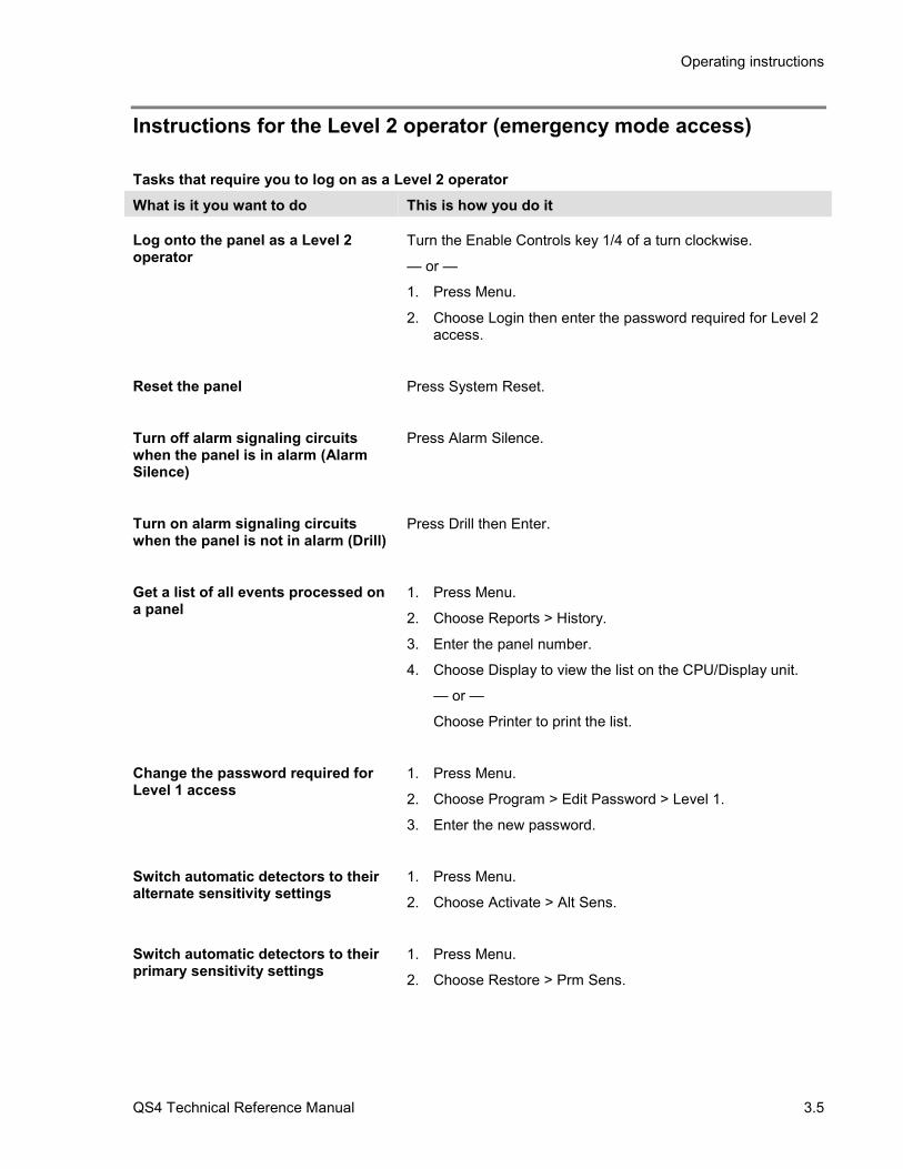
Instructions for the Level 2 operator (emergency mode access)
Tasks that require you to log on as a Level 2 operatorWhat is it you want to do This is how you do it
Log onto the panel as a Level 2operator
Turn the Enable Controls key 1/4 of a turn clockwise.
— or —
1. Press Menu.
2. Choose Login then enter the password required for Level 2access.
Reset the panel Press System Reset.
Turn off alarm signaling circuitswhen the panel is in alarm (AlarmSilence)
Press Alarm Silence.
Turn on alarm signaling circuitswhen the panel is not in alarm (Drill)
Press Drill then Enter.
Get a list of all events processed ona panel
1. Press Menu.
2. Choose Reports > History.
3. Enter the panel number.
4. Choose Display to view the list on the CPU/Display unit.
— or —
Choose Printer to print the list.
Change the password required forLevel 1 access
1. Press Menu.
2. Choose Program > Edit Password > Level 1.
3. Enter the new password.
Switch automatic detectors to theiralternate sensitivity settings
1. Press Menu.
2. Choose Activate > Alt Sens.
Switch automatic detectors to theirprimary sensitivity settings
1. Press Menu.
2. Choose Restore > Prm Sens.
Operating instructions
3.6 QS4 Technical Reference Manual
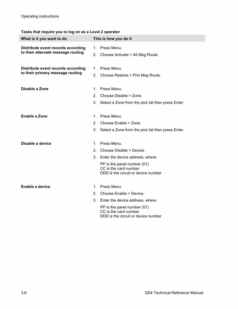
Tasks that require you to log on as a Level 2 operatorWhat is it you want to do This is how you do it
Distribute event records accordingto their alternate message routing
1. Press Menu.
2. Choose Activate > Alt Msg Route.
Distribute event records accordingto their primary message routing
1. Press Menu.
2. Choose Restore > Prm Msg Route.
Disable a Zone 1. Press Menu.
2. Choose Disable > Zone.
3. Select a Zone from the pick list then press Enter.
Enable a Zone 1. Press Menu.
2. Choose Enable > Zone.
3. Select a Zone from the pick list then press Enter.
Disable a device 1. Press Menu.
2. Choose Disable > Device.
3. Enter the device address, where:
PP is the panel number (01)CC is the card numberDDD is the circuit or device number
Enable a device 1. Press Menu.
2. Choose Enable > Device.
3. Enter the device address, where:
PP is the panel number (01)CC is the card numberDDD is the circuit or device number
Operating instructions
QS4 Technical Reference Manual 3.7
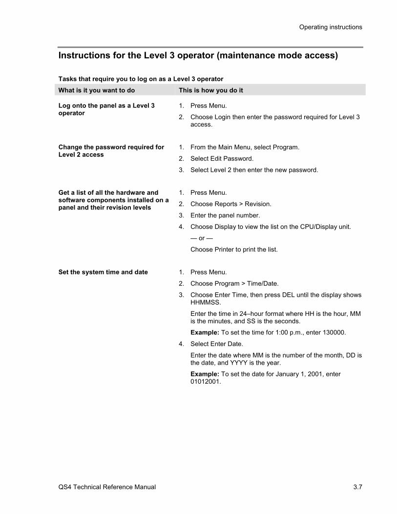
Instructions for the Level 3 operator (maintenance mode access)
Tasks that require you to log on as a Level 3 operatorWhat is it you want to do This is how you do it
Log onto the panel as a Level 3operator
1. Press Menu.
2. Choose Login then enter the password required for Level 3access.
Change the password required forLevel 2 access
1. From the Main Menu, select Program.
2. Select Edit Password.
3. Select Level 2 then enter the new password.
Get a list of all the hardware andsoftware components installed on apanel and their revision levels
1. Press Menu.
2. Choose Reports > Revision.
3. Enter the panel number.
4. Choose Display to view the list on the CPU/Display unit.
— or —
Choose Printer to print the list.
Set the system time and date 1. Press Menu.
2. Choose Program > Time/Date.
3. Choose Enter Time, then press DEL until the display showsHHMMSS.
Enter the time in 24–hour format where HH is the hour, MMis the minutes, and SS is the seconds.
Example: To set the time for 1:00 p.m., enter 130000.
4. Select Enter Date.
Enter the date where MM is the number of the month, DD isthe date, and YYYY is the year.
Example: To set the date for January 1, 2001, enter01012001.
Operating instructions
3.8 QS4 Technical Reference Manual
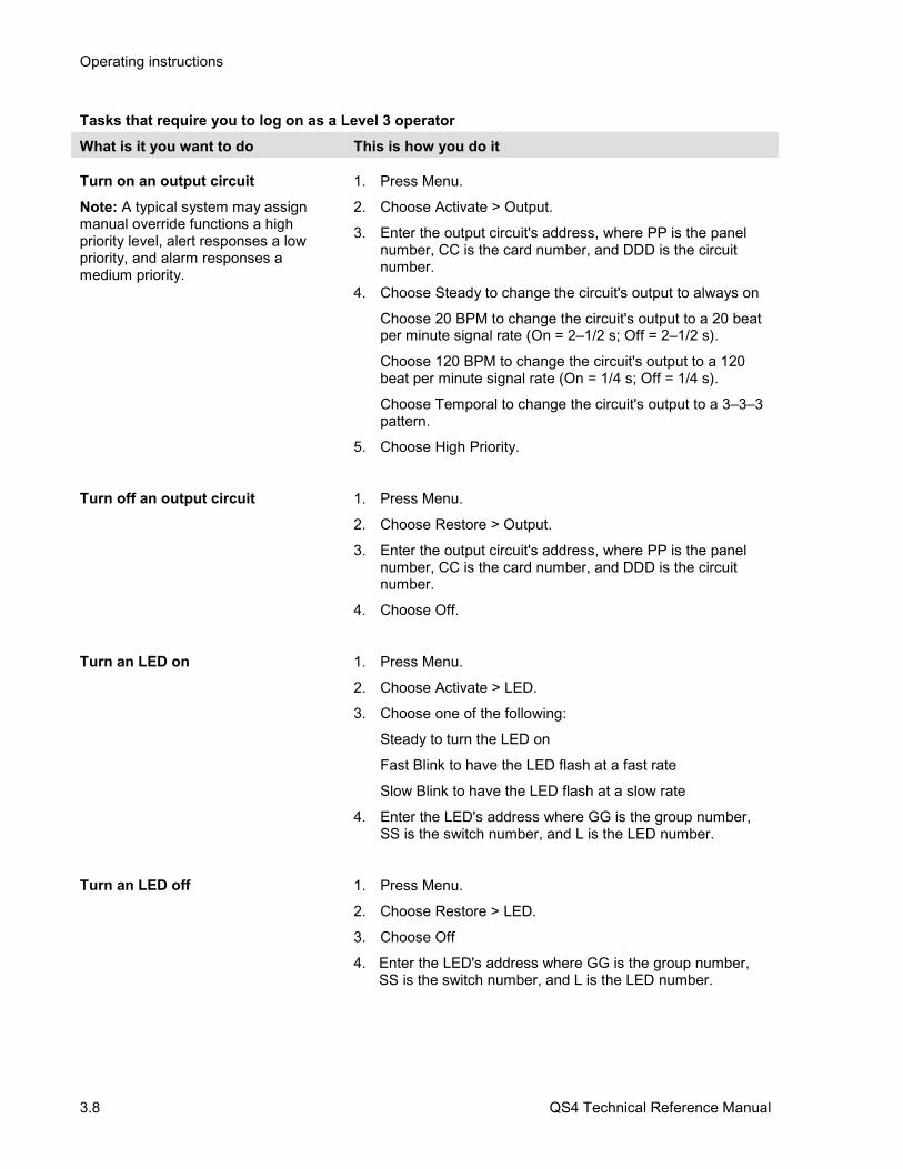
Tasks that require you to log on as a Level 3 operatorWhat is it you want to do This is how you do it
Turn on an output circuitNote: A typical system may assignmanual override functions a highpriority level, alert responses a lowpriority, and alarm responses amedium priority.
1. Press Menu.
2. Choose Activate > Output.
3. Enter the output circuit's address, where PP is the panelnumber, CC is the card number, and DDD is the circuitnumber.
4. Choose Steady to change the circuit's output to always on
Choose 20 BPM to change the circuit's output to a 20 beatper minute signal rate (On = 2–1/2 s; Off = 2–1/2 s).
Choose 120 BPM to change the circuit's output to a 120beat per minute signal rate (On = 1/4 s; Off = 1/4 s).
Choose Temporal to change the circuit's output to a 3–3–3pattern.
5. Choose High Priority.
Turn off an output circuit 1. Press Menu.
2. Choose Restore > Output.
3. Enter the output circuit's address, where PP is the panelnumber, CC is the card number, and DDD is the circuitnumber.
4. Choose Off.
Turn an LED on 1. Press Menu.
2. Choose Activate > LED.
3. Choose one of the following:
Steady to turn the LED on
Fast Blink to have the LED flash at a fast rate
Slow Blink to have the LED flash at a slow rate
4. Enter the LED's address where GG is the group number,SS is the switch number, and L is the LED number.
Turn an LED off 1. Press Menu.
2. Choose Restore > LED.
3. Choose Off
4. Enter the LED's address where GG is the group number,SS is the switch number, and L is the LED number.

Operating instructions
QS4 Technical Reference Manual 3.9
Tasks that require you to log on as a Level 3 operatorWhat is it you want to do This is how you do it
Disable or enable an And Group,Matrix Group, or Time Control
1. Press Menu.
2. Choose Disable or Enable.
3. Choose And if an And group, Matrix if a Matrix group, orTime Control if a time control.
4. Pick a group from the appropriate list and press Enter.
Disable or enable a switch on a zonedisplay
1. Press Menu.
2. Choose Disable > Switch.
— or —
Enable > Switch.
3. Enter the switch address, where GG is the group number,and SS is the switch number.
Disable or enable the mappingfunction on an SLIC
1. Press Menu.
2. Choose Disable > Loop Mapping.
— or —
Enable > Loop Mapping.
3. Enter the card address for the SLIC.
Start a Service Group test 1. Press Menu.
2. Choose Test > Start Test.
3. Select a Service group from the pick list and press Enter.
Cancel a Service Group testNote: The panel automatically resetsafter you cancel a test.
1. Press Menu.
2. Choose Test > Cancel Test.
2. Select a Service group from the pick list and press Enter.

Operating instructions
3.10 QS4 Technical Reference Manual
Instructions for the Level 4 operator (service mode access)
What is it you want to do This is how you do it
Log onto the panel as a Level 4operator
1. Press Menu.
2. Choose Login then enter the password required for Level 4access.
Change the password required forLevel 3 access
1. Press Menu.
2. Choose Program > Edit Password > Edit Password
3. Choose Level 3 then enter the new password.
Change the password required forLevel 4 access
1. Press Menu.
2. Choose Program > Edit Password > Edit Password
3. Choose Level 4 then enter the new password.
Restart a panel 1. Press Menu.
2. Choose Program > Restart > Panel
3. Enter the panel's address.
Reset the alarm history counter 1. From the Main Menu, select Program.
2. Select Reset.
3. Enter the panel's address.

Operating instructions
QS4 Technical Reference Manual 3.11
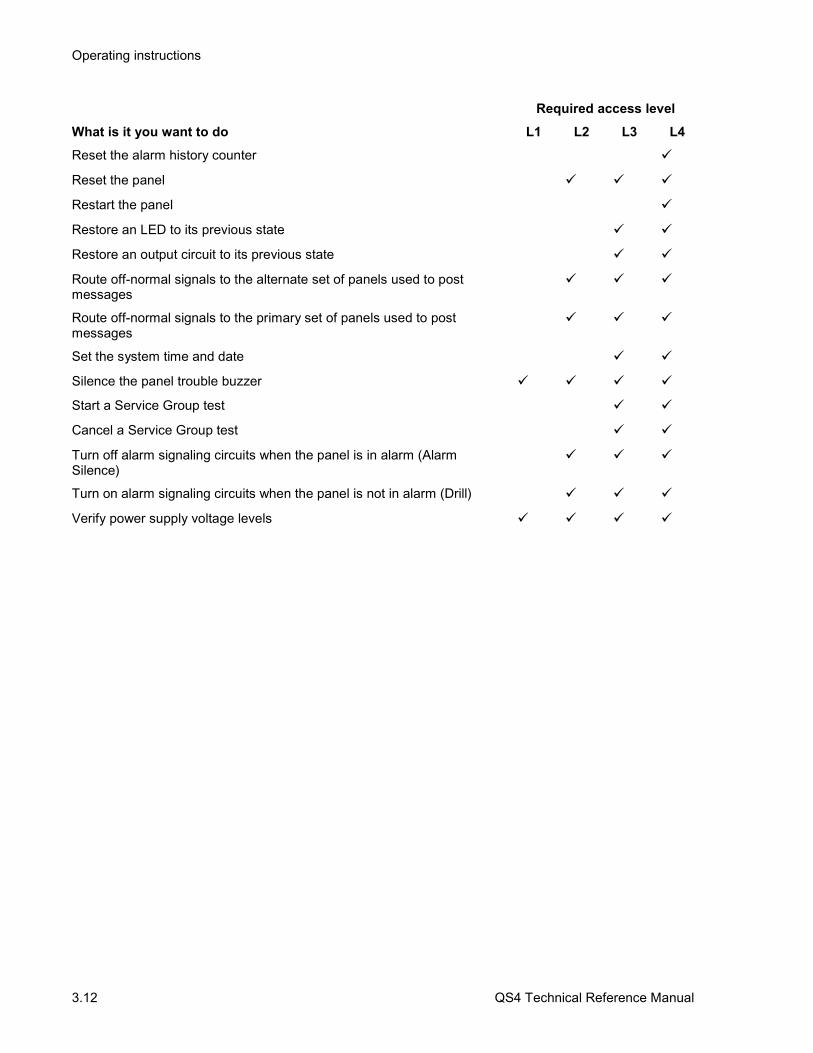
QuickReference listRequired access level
What is it you want to do L1 L2 L3 L4Change smoke detector sensitivity settings to their alternate values
Change smoke detector sensitivity settings to their primary values
Change the current state of an LED (manual override)
Change the current state of an output circuit (manual override)
Change the password required for Level 1 access
Change the password required for Level 2 access
Change the password required for Level 3 access
Change the password required for Level 4 access
Disable or enable a device
Disable or enable a switch on a zone display
Disable or enable a zone
Disable or enable all the devices on a single card
Disable or enable an And Group, Matrix Group, or Time Control
Disable or enable the mapping function on an SLIC
Get a list of all the active points on a panel
Get a list of all the hardware and software components installed on apanel and their revision levels
Get a list of smoke detectors that may require servicing (DIRTY attributegreater than 20%)
Get a list of smoke detectors that require servicing (DIRTY attributegreater than 80%)
Get the attributes for a single smoke detector
Get the attributes for all the smoke detectors on a single SLIC
Identify output devices that are turned on
Identify active points in a Service Group that is being tested
Identify points that are disabled
Identify points that are in their active state
Identify points that are in trouble
Log onto the panel as a Level 2 operator
Log onto the panel as a Level 3 operator
Log onto the panel as a Level 4 operator
Perform a lamp test
Operating instructions
3.12 QS4 Technical Reference Manual
Required access levelWhat is it you want to do L1 L2 L3 L4Reset the alarm history counter
Reset the panel
Restart the panel
Restore an LED to its previous state
Restore an output circuit to its previous state
Route off-normal signals to the alternate set of panels used to postmessages
Route off-normal signals to the primary set of panels used to postmessages
Set the system time and date
Silence the panel trouble buzzer
Start a Service Group test
Cancel a Service Group test
Turn off alarm signaling circuits when the panel is in alarm (AlarmSilence)
Turn on alarm signaling circuits when the panel is not in alarm (Drill)
Verify power supply voltage levels
QS4 Technical Reference Manual 6.1
Chapter 6 Maintenance instructions
SummaryThis chapter provides instructions for maintaining the system.
ContentPseudo point definitions • 6.2
Table 6-1: Main Panel pseudo points • 6.2Table 6-2: Remote Annunciator pseudo points • 6.2Table 6-3: Power Supply pseudo points • 6.3Table 6-4: SLIC card pseudo points • 6.3Table 6-5: Dialer pseudo points • 6.4Table 6-6: General CPU pseudo points • 6.5
Maintenance tasks • 6.6
Maintenance instructions
6.2 QS4 Technical Reference Manual
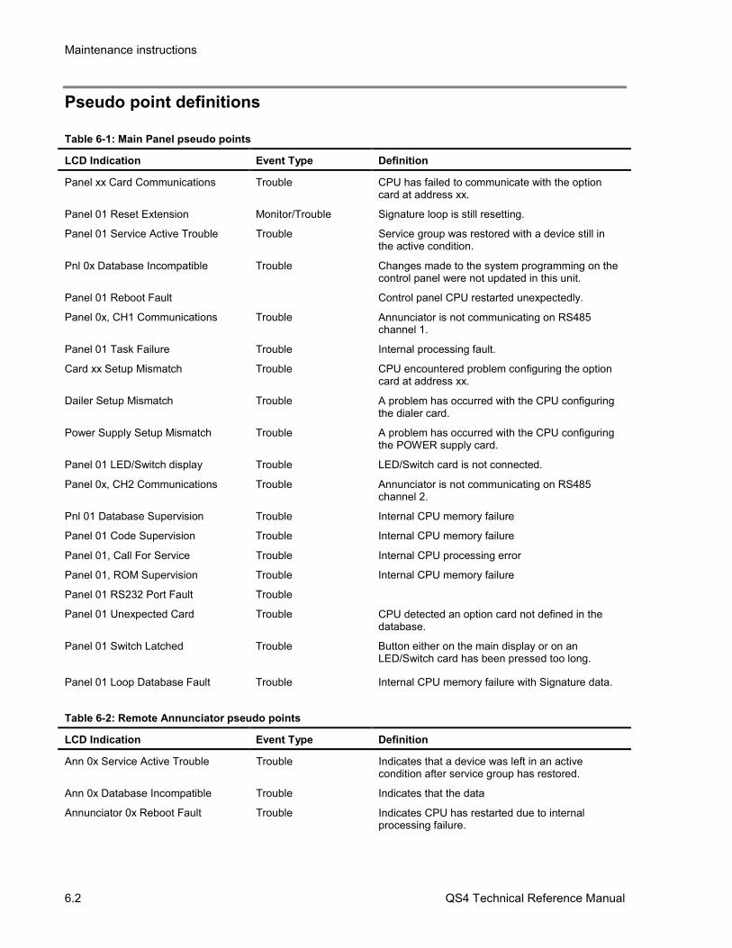
Pseudo point definitions
Table 6-1: Main Panel pseudo points
LCD Indication Event Type Definition
Panel xx Card Communications Trouble CPU has failed to communicate with the optioncard at address xx.
Panel 01 Reset Extension Monitor/Trouble Signature loop is still resetting.
Panel 01 Service Active Trouble Trouble Service group was restored with a device still inthe active condition.
Pnl 0x Database Incompatible Trouble Changes made to the system programming on thecontrol panel were not updated in this unit.
Panel 01 Reboot Fault Control panel CPU restarted unexpectedly.
Panel 0x, CH1 Communications Trouble Annunciator is not communicating on RS485channel 1.
Panel 01 Task Failure Trouble Internal processing fault.
Card xx Setup Mismatch Trouble CPU encountered problem configuring the optioncard at address xx.
Dailer Setup Mismatch Trouble A problem has occurred with the CPU configuringthe dialer card.
Power Supply Setup Mismatch Trouble A problem has occurred with the CPU configuringthe POWER supply card.
Panel 01 LED/Switch display Trouble LED/Switch card is not connected.
Panel 0x, CH2 Communications Trouble Annunciator is not communicating on RS485channel 2.
Pnl 01 Database Supervision Trouble Internal CPU memory failure
Panel 01 Code Supervision Trouble Internal CPU memory failure
Panel 01, Call For Service Trouble Internal CPU processing error
Panel 01, ROM Supervision Trouble Internal CPU memory failure
Panel 01 RS232 Port Fault Trouble
Panel 01 Unexpected Card Trouble CPU detected an option card not defined in thedatabase.
Panel 01 Switch Latched Trouble Button either on the main display or on anLED/Switch card has been pressed too long.
Panel 01 Loop Database Fault Trouble Internal CPU memory failure with Signature data.
Table 6-2: Remote Annunciator pseudo points
LCD Indication Event Type Definition
Ann 0x Service Active Trouble Trouble Indicates that a device was left in an activecondition after service group has restored.
Ann 0x Database Incompatible Trouble Indicates that the data
Annunciator 0x Reboot Fault Trouble Indicates CPU has restarted due to internalprocessing failure.

Maintenance instructions
QS4 Technical Reference Manual 6.3
LCD Indication Event Type Definition
Ann 0x, CH1 Communications Trouble Indicates failure to communicate with the mainpanel on RS485 channel 1.
Annunciator 0x Task Failure Trouble Internal software failure
Ann 0x, LED/ Switch Display Trouble Indicates that a SL30-x has been disconnected oris connected but not defined.
Ann 0x, CH2 Communications Trouble Indicates failure to communicate with the mainpanel on RS485 channel 2.
Ann 0x Database Supervision Trouble Internal memory failure
Ann 0x Code Supervision Trouble Internal memory failure
Ann 0x, Call For Service Trouble Internal software failure
Ann 0x ROM Supervision Trouble Internal memory failure
Ann 0x RS232 Port Fault Trouble
Ann 0x Program Mode Trouble Panel has entered program mode.
Ann 0x Switch Latched Trouble Indicates that a button either on the main displayor on an SL30-x has been pressed to long.
Annunciator 0x Power Fault Trouble Indicates a loss of power on either of the 24vdcinputs to the RAI card.
Table 6-3: Power Supply pseudo points
LCD Indication Event Type Definition
Battery Charger Fault Trouble This fault will occur when the battery chargercharging voltage falls below 20.4vdc.
Battery Wiring or Battery Fault Trouble Caused by an open in the battery wiring or if thebatteries are below 20.4vdc.
Aux Power 1/2 Shorted Trouble This point occurs when Aux 1 or Aux 2 power isshorted on the PS6
Aux Power 3 Shorted Trouble This point occurs when Aux 3
Smoke Power Shorted Trouble This point occurs when smoke power is shorted
Primary AC Power Failure Trouble Caused by loss of AC or very low AC.
Excessive Battery Current Trouble Will go active when PS6 detects over currentcondition
Check System Wiring Trouble Indicates a ground fault exists on field wiring.
Power Supply Card RAM Fault Trouble Internal memory fault
Power Supply Card ROM Fault Trouble Internal memory fault
Power Supply EEPROM Fault Trouble Internal memory fault
Table 6-4: SLIC card pseudo points
LCD Indication Event Type Definition
Card 0x, Loop Wiring Problem Trouble Indicates a break on a Class A signature loop
Card 0x Map Fault Trouble Signature map is different than the one written inmemory

Maintenance instructions
6.4 QS4 Technical Reference Manual
LCD Indication Event Type Definition
Card 0x, Mapping In Progress Monitor Indicates Signature devices are in the process ofbeing mapped.
Card 0x Unconfig. Device Trouble Indicates that a new signature device has beendetected on a loop.
Card 0x, Line Initialization Monitor Occurs after power up or a restart. Indicatessignature devices are being initialized.
Card 0x, Loop Ground Fault Trouble Indicates a ground fault on a signature module.
Card 0x, LIM Driver Fault Trouble Internal hardware failure.
Card 0x, RAM Supervision Trouble Internal memory fault
Card 0x, ROM Supervision Trouble Internal memory fault
Card 0x, EEPROM Supervision Trouble Internal memory fault
Table 6-5: Dialer pseudo points
LCD Indication Event Type Definition
Primary Phone Line:check Telco Trouble Telephone line has low or no voltage
Secondary Phone Line:check Telco Trouble Telephone line has low or no voltage
Pri. Receiver Failed to answer Trouble Dialer attempted to dial event to CMS but did notget an answer.
Sec. Receiver Failed to answer Trouble Dialer attempted to dial event to CMS but did notget an answer.
Dialer Account 1 Fault Trouble Indicates dialer did not get proper handshake forevent sent to the CMS for Account 1.
Dialer Account 2 Fault Trouble Indicates dialer did not get proper handshake forevent sent to the CMS for Account 2.
Dialer Account 3 Fault Trouble Indicates dialer did not get proper handshake forevent sent to the CMS for Account 3.
Dialer Account 4 Fault Trouble Indicates dialer did not get proper handshake forevent sent to the CMS for Account 4.
Dialer Account 5 Fault Trouble Indicates dialer did not get proper handshake forevent sent to the CMS for Account 5.
Dialer Account 6 Fault Trouble Indicates dialer did not get proper handshake forevent sent to the CMS for Account 6.
Dialer Account 7 Fault Trouble Indicates dialer did not get proper handshake forevent sent to the CMS for Account 7.
Dialer Account 8 Fault Trouble Indicates dialer did not get proper handshake forevent sent to the CMS for Account 8.
Dialer ROM Fault Trouble Internal memory fault
Dialer Queue Overflow Trouble Indicates that too many dialer messages are tryingto be sent.
Dialer Card, RAM Supervision Trouble Internal memory fault

Maintenance instructions
QS4 Technical Reference Manual 6.5
Table 6-6: General CPU pseudo points
LCD Indication Event Type Definition
Startup Response Monitor Monitor point that goes active on system startup orafter restart.
First Alarm Alarm Occurs anytime that the system goes into alarmfor the first time.
First Supervisory Supervisory Occurs anytime that the system goes intosupervisory for the first time.
First Trouble Trouble Occurs anytime that the system goes into atrouble for the first time.
First Monitor Monitor Occurs anytime that the system goes into amonitor condition for the first time.
Evacuation
Drill Monitor This point will go active anytime drill is pressed.
Alarm Silence Monitor This point will go active anytime alarm silence ispressed.
Two Stage Expiration
Reset Monitor This point goes active anytime reset is pressed.
Reset Phase 1 Monitor Active during the power down phase of reset.
Reset Phase 2 Monitor Active during the retard phase of reset.
Reset Phase 3 Monitor Active during the restoration phase of reset.
First Disable Trouble Activated the first time an item is disabled from thefront menu.
First Test Trouble Activated the first time a service group is startedfrom the front menus.
Two Stage Timer Started
User Trouble Trouble Triggered by custom programming.
Maintenance instructions
6.6 QS4 Technical Reference Manual
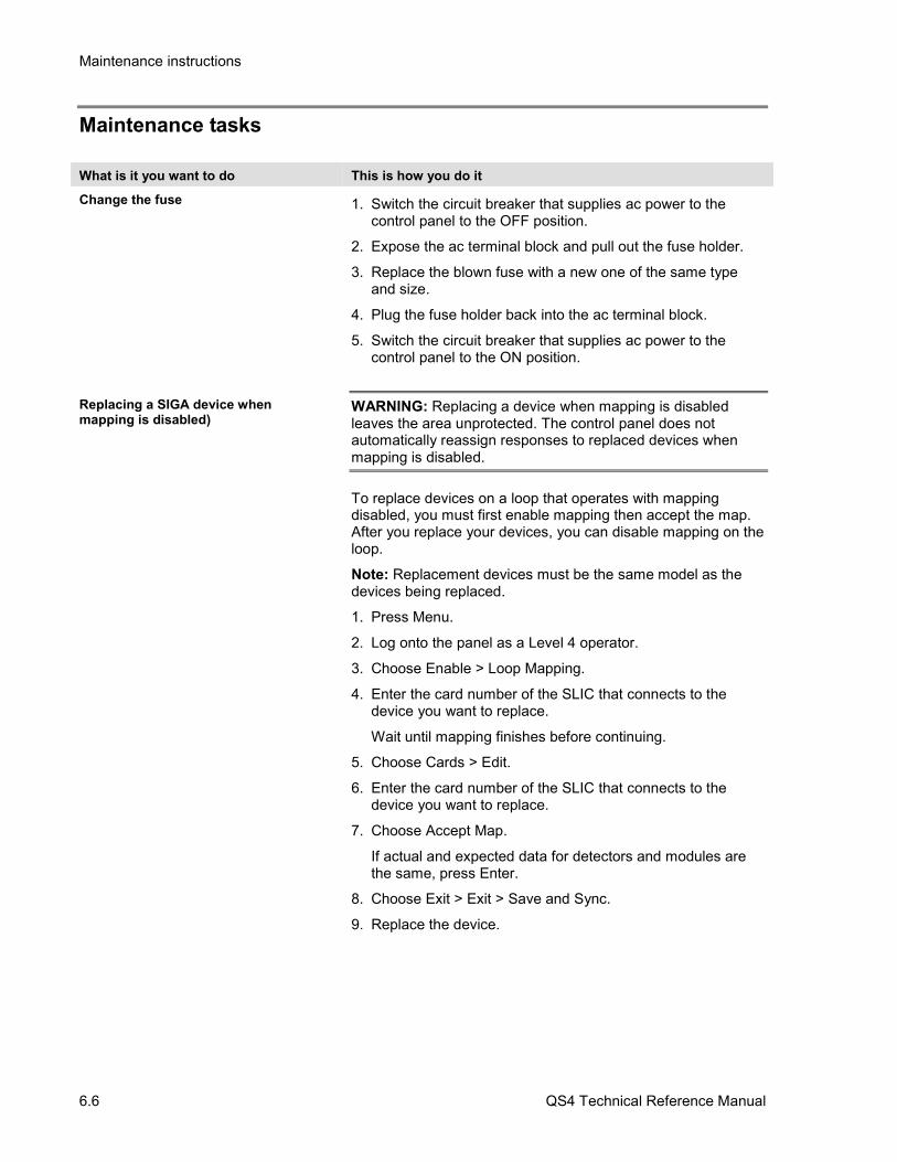
Maintenance tasks
What is it you want to do This is how you do it
Change the fuse 1. Switch the circuit breaker that supplies ac power to thecontrol panel to the OFF position.
2. Expose the ac terminal block and pull out the fuse holder.
3. Replace the blown fuse with a new one of the same typeand size.
4. Plug the fuse holder back into the ac terminal block.
5. Switch the circuit breaker that supplies ac power to thecontrol panel to the ON position.
Replacing a SIGA device whenmapping is disabled)
WARNING: Replacing a device when mapping is disabledleaves the area unprotected. The control panel does notautomatically reassign responses to replaced devices whenmapping is disabled.
To replace devices on a loop that operates with mappingdisabled, you must first enable mapping then accept the map.After you replace your devices, you can disable mapping on theloop.
Note: Replacement devices must be the same model as thedevices being replaced.
1. Press Menu.
2. Log onto the panel as a Level 4 operator.
3. Choose Enable > Loop Mapping.
4. Enter the card number of the SLIC that connects to thedevice you want to replace.
Wait until mapping finishes before continuing.
5. Choose Cards > Edit.
6. Enter the card number of the SLIC that connects to thedevice you want to replace.
7. Choose Accept Map.
If actual and expected data for detectors and modules arethe same, press Enter.
8. Choose Exit > Exit > Save and Sync.
9. Replace the device.