technical procedures - brutaldeluxe.fr · o contents macintosh iici '* apple technical...
TRANSCRIPT

'* Apple Technical Procedures
Macintosh IIci
Technical Procedures
o TABLE OF CONTENTS
Section 1 Basics
Section 2Take-Apart
1.3 Product Description1.3 New Features1.3 Macintosh IIci Configurations1.5 Connector Identification1.5 Back Panel1.6 Internal Connectors1.7 Module Identification1.8 Macintosh IIci System Features1.8 Macintosh IIci Logic Board1.10 Apple FDHD Drive1.14 Specifications1.17 Theory of Operation1.17 Introduction1.17 System Startup1.19 Logic Board1.22 Input/Output Interface1.26 Real-Time Clock1.26 NuBus Interface1.27 Cache Connector1.28 Parity1.28 Power Control1.29 Power Supply1.29 Fuses1.29 Internal Floppy Disk Drives1.30 Internal Hard Disk SCSI
2.2 Electrostatic Discharge Prevention2.3 Top Lid2.4 Interface Cards2.5 Speaker Bracket and Speaker2.8 Power Supply2.10 Fan Bracket and Fan2.12 Hard Disk Drive2.16 Disk Drive Carrier and Floppy Disk Drive2.21 Reset/Interrupt Switch2.22 Main Logic Board
Macintosh lici Sep 89 Contents / i
Section 3Diagnostics
Diagnostics not available at time of printing
Section 4Troubleshooting
Section 5-Additional Procedures
4.34.34.34.34.34.44.54.74.74.74.84.84.84.84.94.94.104.104.114.134.144.144.164.184.194.204.224.224.224.234.244.264.264.26
5.35.35.35.65.65.65.7
IntroductionGeneral InformationBefore You StartError ChordsHow to Use the Symptom ChartHow to Use the Troubleshooting Flowcharts
Things to RememberModule Exchange Information
Logic Board ConfigurationInternal Hard Disk SCSI
Startup and Error ChordsIntroductionStartup ChordError Chords
Symptom ChartBuilt-in Video ProblemsFloppy Drive ProblemsSCSI ProblemsPeripheral ProblemsMiscellaneous Problems
Macintosh IIci FlowchartsFlowchart 1 NotesFlowchart 2 NotesFlowchart 3 NotesFlowchart 4 NotesFlowchart 5 Notes
SIMM VerificationIntroductionIsolating to the Customer's SIMMsVerificationVerification Flowchart Notes
Battery VerificationIntroductionVerification Procedure
Battery ReplacementStorage and HandlingDisposal
Logic Board RAM Identification and UpgradesIntroductionIdentificationUpgrades
ii / Contents Sep 89 Macintosh llei

IllustratedParts List
IPL.3
IPL.5IPL.5
IPL.7IPL.9IPL.11IPL.13
Macintosh IIci-System Exploded View(Figure 1)
Macintosh IIci-Logic Board (Figure 2)Macintosh IIci-Logic Board with Parity
(Figure 2)Keyboard (Figure 3)Extended Keyboard (Figure 4)Mouse (Figure 5)ISO Keyboard (Figure 6)
©Apple Computer, Inc., 1989. No portion of this document may be reproduced in any formwithout the written permission of Apple Computer, Inc.MacTest, Apple Desktop Bus, and EtherTalk are trademarks of Apple Computer, Inc.Macintosh, AppleCAT, NUX, AppleTalk, Apple, and the Apple logo are registered trademarks ofApple Computer, Inc.
Macintosh IIci Sep 89 Contents / iii


o CONTENTS
Macintosh IIci
'* Apple Technical Procedures
Macintosh IIci
Section 1 - Basics
1.3 Product Description1.3 New Features1.3 Macintosh IIci Configurations1.5 Connector Identification1.5 Back Panel1.6 Internal Connectors1.7 Module Identification1.8 Macintosh IIci System Features1.8 Macintosh IIci Logic Board1.10 Apple FDHD Drive1.14 Specifications1.17 Theory of Operation1.17 Introduction1.17 System Startup1.19 Logic Board1.22 Input/Output Interface1.26 Real-Time Clock1.26 NuBus Interface1.27 Cache Connector1.28 Parity1.28 Power Control1.29 Power Supply1.29 Fuses1.29 Internal Floppy Disk Drives1.30 Internal Hard Disk SCSI
Sep 89 Basics /1.1


o PRODUCT DESCRIPTION
The Macintosh® IIci is a high-performance, openarchitecture Macintosh computer with enhancedfunctionality. It is designed to run existing softwarewhile providing the power, flexibility, andexpandability necessary for future applications.
New Features
Macintosh IIclConfigurations
Floppy-OnlySystems
Hard Disk Systems
The Macintosh IId has the following features:
• Increased speed-25 MHz (true 32-bit support)• Built-in video support• Parity support (optional)• 512K of ROM• RAM cache connector
The Macintosh IIci comes in a variety of configurations.Below are four configurations that are offered. Theseare not the only possible configurations. Because of theflexibility of this unit, you may see units with differentamounts of RAM and with other SCSI 3.5-inch hard diskdrives. Presented here are basic configurations andsome of the limitations.
The floppy-only system includes the following elements:
• 1 megabyte (MB) of RAM• One Apple FDHD drive
(Floppy Disk High Density, 1.4 MB Drive)
The hard disk systems include the following elements:
The 1 MB system with a 40 MB HDA:• 1 MB of RAM• One Apple FDHD drive
(Floppy Disk High Density, 1.4 MB Drive)• 40 MB SCSI internal hard disk
Macintosh IIci Sep 89 Basics /1.3

Enhancements
The 4 MB system with an SO MB HDA:• 4 MB of RAM• One Apple FDHD drive
(Floppy Disk High Density, 1.4 MB Drive)• SO MB SCSI internal hard disk
The 4 MB system with A/UX®:• 4 MB of RAM• One Apple FDHD drive
(Floppy Disk High Density, 1.4 MB Drive)• SO MB SCSI + A/UX (Apple UNIX®) on a special
internal hard disk
The 4 MB system with parity:• 4 MB of RAM• One Apple FDHD drive
(Floppy Disk High Density, 1.4 MB Drive)• SO MB SCSI internal hard disk
Note: The limitation of the 1 MB system is that thebuilt-in video uses 320K of memory to support a640 x 4SO screen at S bits/pixel (and 640 x S70 at4 bits/pixeOj therefore, the system will default to1 bit/pixel. This leaves 6S0K of memory available forapplication use.
Note: The RAM cache slot is not compatible with theSE/30 direct slot.
The following enhancements can be added to any of thesystems:
• SOOK, 3.5-inch external disk drive or external 1.4MB FDHD (the Macintosh IIci will not support theHD20, or any 400K drives)
• 1 to S MB of RAM (up to 12S MB when largerDRAMs become available)
• Any Apple 20, 40, or SO MB (or larger, withinlimits) 3.5-inch internal SCSI hard disk drive
• Up to 6 external SCSI devices of any size or kind
IMPORTANT: To maintain system functionality, AlUXcustomers planning to use the Macintosh /lci and/or AppleFDHD drive must upgrade AlUX software to at leastversion 1.0.1.
1.4 / Basics Sap 89 Macintosh IIci

o CONNECTOR IDENTIFICATION
BackPanel
The back panel of the Macintosh IIci has eight built-inports and two connectors, as listed below. The numberbeside the item below corresponds to the numberedarrow in Figure 1.
1. Apple Desktop BUS™ 1 and 22. Stereo sound port3. Serial port 24. Serial port 15. Video port6. SCSI port7. External disk drive connector8. Locking power switch9. AC power connector
10. Switched (courtesy) monitor connector
FIGURE 1
Macintosh IIci Sep 89 Basics /1.5

InternalConnectors
The Macintosh IIci logic board has nine connectors andone jumper. In the list below, the number beside theconnector or jumper name corresponds to the numberedarrow in Figure 2.
1. Power supply connector for the logic board2. Internal SCSI connector3. Power connector for internal SCSI4. Internal disk drive connector5. RAM SIMM connectors6. Speaker connector7. ROM jumper8. NuBus slots9. ROM SIMM connector
10. Cache card connector
FIGURE 2
1.6/ Basics Sep 89 Macintosh IIci

o MODULE IDENTIFICATION
FIGURE 3
Module Components
Macintosh IIci
1. Top lid2. Fan bracket3. Fan4. Power supply5. Logic board6. Outer case7. Power lamp lens
Sap 89
8. Diode light assembly9. Programmer's switch
10. Floppy disk11. Spea~er
12. Speaker bracket13. Disk carrier14. Hard disk
Basics /1.7

o MACINTOSH IIci SYSTEM FEATURES
The Macintosh lIci is an enhanced-performanceMacintosh lIex that includes the following new orupgraded components:
• Motorola 68030 microprocessor running at 25 MHz• 512K of ROM• RBV (RAM-Based Video chip)• MDU (Memory Decode Unit)• Nu-Chip 30 (NuBus controller chip)• NuBus Transceivers (NuBus support chips)• Cache Card connector• PGC (Parity-Generating Chip) (special orders)
Macintosh IIciLogic Board
At the heart of the Macintosh lIci is the Motorola68030 microprocessor (Figure 4, #1). The 68030 is atrue 32-bit microprocessor that is fully compatible withearlier 16- and 24-bit Macintosh microprocessors. Thishigh-performance microprocessor runs at 25 MHz and isdesigned to handle paged memory management, therebyeliminating the HMMU (or PMMU). With this increasedspeed, and by taking advantage of the 68030 burstaccess capability (which enables the CPU to read groupsof instructions or data in fewer clock cycles than innormal access mode), the Macintosh lIci deliverssignificantly higher performance than the existingMacintosh systems.
The Macintosh lIci logic board includes four 128K x 8bits in 32-pin DIP soldered-in 512K ROM (Figure 4, #2).It also contains a 64-pin SIMM (Single In-line MemoryModule) socket (Figure 4, #3) that allows for futureROM upgrades to the Macintosh IIci without changingthe main logic board. These ROM chips include codethat supports the built-in video, parity, virtual memory(used on A/UX systems), and 32-bit QuickDraw™. Thecode supports future upgrades to the MacintoshOperating System.
Note: When a new ROM SIMM is installed, theexisting DIP ROM will not have to be removed fromthe board. For the new ROM to be recognized, it willjust be a matter of removing a jumper (Figure 4, #4) onthe logic board.
1.8/ Basics Sap 89 Macintosh !lei

4 o IIHBo l1li om IIl1lil1lil1li e:i ~
',', ',', ',', ',', il
IT
~ I~
FIGURE 4
rrffi'iIlml
Having the RBV (RAM-Based Video) chip (Figure 4, #5)on the logic board enables the Macintosh IIci to drive a640 x 480 screen at up to 8 bits/pixel and a 640 x 870screen at up to 4 bits/pixel without the need for avideo card. The chip uses a section of the RAM as ascreen frame and retrieves the video data, which isthen converted for display by a video DAC (digital-toanalog converter) and sent out through the DB-IS videoport.
For decoding address space, a new chip called the MDU(Memory Decode Unit) has been added (Figure 4, #6).The chip decodes device selection for the physicaladdress map, and addresses both banks of RAM memory.Unlike earlier Macintosh units, this allows largeramounts of memory to be installed in bank B.
The NuChip 30 chip (Figure 4, #7) is a new version ofthe NuBus chip (Macintosh Hex). It is a controller chipthat controls the NuBus transceivers through which datatransfers to and from the NuBus slots.
Macintosh IIci Sap 89 Basics /1.9

Apple FDHDDrive
The new cache connector (Figure 4, #8) allows the useof a cache card. The use of a cache card increases theeffective speed of the main memory by providing theCPU with a copy of the most frequently used data morequickly than the memory that the cache supports. Thecache stores the most recently accessed data andinstructions in a small bank of high-speed memory,which the CPU can access faster.
CAUTION: The cache slot is not compatible with theSE/30 direct slot. Trying to use an SE/30 direct board inthe cache slot will result in damage to the main logicboard and the direct board.
The last of the new features on the Macintosh lId isthe ability to have parity checking if the Macintosh IIciis a special-order unit. If the system has paritychecking, it will have a PGC (Parity-Generating ChipFigure 4, #9) installed on the logic board and will alsohave special 9-bit parity SIMMs installed in the RAMSIMM sockets. The PGC will generate an extra bit ofinformation for each byte of information stored inmemory so that the total number of "on" bits add to anODD number. When the data is read from memory, thebyte is checked to determine whether the data has beencorrupted (does the byte stiU add to an odd number of"on bits"?). If so, the system is halted and a restartmust be done.
The SWIM chip (Figure 4, #10) enables the Apple FDHDdrive to read and write both GCR (Group-CodedRecording) and MFM (Modified Frequency Modulation)data formats.
The Apple FDHD drive is a high-density (1.4 MB), 3.5inch disk drive for the Macintosh IIci system. Inaddition to high-capacity data storage, the Apple FDHDdrive provides data exchangeability between Apple(GCR data format) and MS-DOS (MFM data format)systems. The Apple FDHD drive is also fully backwardcompatible with the current 400K and 800K diskformats.
//
1.1 0 / Basics Sap 89 Macintosh llei

Identification The Apple FDHD drive cannot be distinguished from400K and SOOK format disk drives. However, since theApple FDHD drive is the only drive supportedinternally, you should not have any problem. If yoususpect that an SOOK drive has been installedinternally, you can tell by removing the top lid andlocating the microswitches (Figure 5, #1) at the front ofthe drive. The Apple FDHD drive has threemicroswitches; the SOOK drive has only twomicroswitches.
FIGURE 5
You can also identify an Apple FDHD drive by removingit from the Macintosh IIci and checking themanufacturer's label (Figure 6) on the bottom of thedrive: all high-density drives have the note 2MB onthe label.
FIGURE 6
Macintosh IIci Sap 89 Basics / 1.11

High-Density
CAUTION: High-density media are more likely to haveproblems than low-density media. To avoid media-relatedproblems, use only known-good media or high-densitymedia bearing the Apple label.
The Apple FDHD drive can read, write, and format 400Kand 800K media data disks. However, special highdensity, 3.5-inch disks that take full advantage of theincreased capacity of the Apple FDHD drive are alsoavailable. To avoid media-related problems when usingthe Apple FDHD drive, Apple advises using highdensity media bearing the Apple label.
As shown in the drive and media compatibility matrix(Figure 7), 400K drives can read, write, and format bothsingle-sided media and double-sided media (in 400Kformat only). The 800K drives can also read, write, andformat both single- and double-sided media. However,Apple does not recommend using high-density media ineither 400K or 800K disk drives. Data saved to highdensity media using 400K or 800K drives is unreliableand could be lost later. The Apple FDHD drives canread, write, and format single-sided, double-sided, andhigh-density media. In addition, Apple FDHD drives canread, write, and format nOK and 1.4 MB double-sidedIBM (MFM) format media.
FORMATDrive Media
400K(GCR) SOOK(GCR) 720K(MFM) 1.4 MB (MFM)
400K Single-Sided RJW/F X X X400K Double-Sided RJW/F X X X400K High-Density NR X X X
BOOK Single-Sided RJW/F NR X XBOOK Double-Sided RJW/F RJW/F X XBOOK High-Density NR NR X X
FDHD Single-Sided RJW/F NR X XFDHD Double-Sided RJW/F RJW/F RJW/F XFDHD High-Density X X X RJW/F
LEGEND: RWFXNR
ReadWriteFormatNot AllowedNot Recommended
FIGURE 7
1.12 / Basics Sep 89 Macintosh IIci
Note: To help understand drive and media formatcompatibility, think in terms of the drive/media oflowest capacity. For example, if your system has bothan external BOOK drive and an Apple FDHD drive, toensure media format compatibility between the twodrives you must use BOOK media (the drive and media oflowest capacity).
Macintosh IIci Sap 89 Basics / 1.13

o SPECIFICAliONS
Processor
Clock Frequency
Addressing
Coprocessor
ROM
RAM
Slot Expansion
Sound
Disk Drives
Hard Disk
Mc68030 CPU, 32-bit architecture with burstingsupport
25.0 MHz
32-bit internal registers32-bit address busSupports paged memory management
25 MHz Mc68882 Floating-Point Unit (FPU)Accepts optional coprocessor cards installed in NuBusexpansion slots.
512K
1 MB expandable to 8 MB (expandable to 128 MB whenSIMMs with higher-density DRAM chips becomeavailable); additional expandability through NuBus slots
Three NuBus expansion slotsPower available per slot+ 5 V 12 Amps 10 Watts+12 V 0.175 Amps 2.1 Watts-12 V 0.150 Amps 1.8 Watts
One RAM cache slotPower available
+5 V 1 Amp 5 Watts
Apple Sound Chip (ASC) , including four-voice wavetable synthesis and stereo sampling generator capableof driving stereo mini phone jack headphones or stereoequipment
Internal Apple FDHD driveExternal 3.5-inch 800K disk drive
SCSI hard disks (internal/optional external)
1.14 / Basics Sap 89 Macintosh lIei

SCSI
Serial Ports
Video Display
Keyboard
Mouse
Input Power
SystemOutput Power
Clock/calendar
Operating Temperature
Storage Temperature
One external SCSI port (DB-25)
Two RS-422 (RS-232 compatible) serial ports, 230.4Kbaud maximum (Mini DIN-8)
Built-in video support with external video port tosupport the Apple High-Resolution MonochromeMonitor, AppleColor High-Resolution RGB Monitor, andthe Apple Portrait Display
Will also support multiple external color andmonochrome monitors connected through video cards inNuBus expansion slots
Apple Keyboard or Apple Extended Keyboard connectedthrough Apple Desktop Bus ports (Mini DIN-4)
Apple Desktop Bus mouse (Mini DIN-4)
100 to 240 volts AC RMS automatically configured50-60 Hz single phase130 Watts maximum, not including monitor conveniencepower connector load
Output receptacle: 100-240 Volts AC, RMS(determined by actual input voltage)
DC power: 90 watts maximum+5 Volt 12.0 Amps (60 Watts)
+12 Volt 15 Amps (18 Watts)-12 Volt 1.0 Amps (12 Watts)
CMOS custom chip with long-life lithium battery256 bytes of parameter memory
10° C to 40° C50° F to 104° F
-40° C to 47° C-40° F to 116.6° F
Macintosh lIei Sap 89 Basics / 1.15

Relative Humidity
Altitude
1.16 / Basics
5% to 95% (noncondensing)
o to 3048 m (0 to 10,000 ft.)
Sap 89 Macintosh llci
o THEORY OF OPERATION
Introduction
SystemStartup
The Macintosh IIci computer is made up of three basicmodules: the logic board, the power supply, and thedisk drives. The computer can have one internal floppydisk drive and can have one internal SCSI hard disk.
The information here will give you an understanding ofhow the Macintosh IIci computer works. Thisunderstanding, in turn, will assist you in performinglogical troubleshooting on this system.
When the computer is turned on, the system begins acarefully synchronized sequence of events. First, ROMis mapped by the MDU to physical $0000 0000. Thisenables the starting address, retrieved by the 68030 onreset, to be stored in ROM. After the first access tothe true ROM address space, the normal memory map isimposed by the MDU. The only change from one map tothe other is that the power-up map selects ROM forlow addresses, whereas the normal map selects RAM forthat address space.
The software determines the memory size and compilesa table describing the current memory configuration.The MMU is then programmed, based on this table, toprovide contiguous logical memory from the potentiallynoncontiguous physical segments in Bank A and B.The 24/32-bit memory map is designed to allowexisting Macintosh software to use a 24-bit addressmode while new software can use the full 32-bitaddress space. The mapping is implemented simply anddirectly.
At this point the disk startup process begins. Thesystem looks for a readable disk in the available diskdrives in the following order:
1) Internal floppy disk drive2) External floppy disk drive3) Setup device set in the control panel4) SCSI devices in declining order of device ID
(6 to 0)
Note: If the battery is removed or the contents of theparameter RAM is destroyed, the setup device defaultsto the device with ID=O.
Macintosh IIci Sap 89 Basics /1.17

Once a readable disk is found, it is read and the diskstartup process is completed.
PhysicalAddress Map
RAM &Video
De>Ace Selects NuBus Slots.:.:.:.:.:.:.:.:.:.:.:.:.:.:.:.:.:.:.:.:.:.:.:::::. 110 Devices
ROM
MDU
(024·31)
I(DO-31)
(AO·31l
(AO.l,4)
VKleollits
NuChp30(AO,l,23-31) NuBus 1-'<.-------. A
Ij(A~2~-22)t:l;;:h~Con§trol~leI~t~ NuBus cr(DO-31)IIDO-31l Transceivers1IIIIliiiii ~
::...:..:'"
Left ChalVlel SonY. ~:nternal Externalr:~=~~C~US~Dm~Am~np~.. SpeakerI Righi Channel AUd~Port
Cus~mp.I-"'------(1!I,",·
Video
~
ExternalSCSI Port
NuBusConnectors
mmm::: ::: :::
Wllim-= ..... ...,...
RTC II Real Time Clock
AppleDesktop
~rtsADB I I ~
Apple Desklop II--_L..--_~{":_:')Bus Troocelver
Port for Internal Hard Disk
R G&B
SvncSlaoals
Port for Internal Floppy Disk External Floppy
e::p!Disk Port..,..,...,...,.~
Serial
Channel ADrivers
POll AIModem) ~Channel B I R~~S I Pori B(Printer)
.........
(024-31)VDAC
4780lA&Color
Lookup
(024-31)ASC
SolrldChb
VIAl
(024·31) VersafleiltelfaceAdapter
SCSI(024·31) 53C80
SmallComputerSystemilterface
(024·31)SWIM
F~yDisk
Controller
SCC(024·31) 8530
serialCommuri·
cationsController
(A2·4)
(A1,2)
lA4-61
IA9-12)
FIGURES
1.18 / Basics Sep 89 Macintosh IIci

Logic Board
Microprocessors
Numeric Coprocessor
RAM
The logic board is the heart of the system, the placewhere all processing of information takes place. Whatfollows is a list of the major components of theMacintosh llci logic board and the functions theyperform.
By using the block diagram in Figure 8 as you readthrough the various sections, you will get a clearerunderstanding of how the logic board works.
The Macintosh llci contains a 68030 microprocessor,which is a true 32-bit processor but also supports both24- and 16-bit processing modes. It runs at 25 MHz forhigh performance. When running in the 24-bitaddressing mode, the Macintosh llci is compatible withthe majority of existing Macintosh applications.
When working in A!UX (Apple UNIX), the 68030microprocessor incorporates instruction sets forhandling paged memory management, therebyeliminating the need for an HMMU or PMMU (as foundin the Macintosh 11). When data is sought from a memorylocation that isn't in the RAM, the 68030 swaps the pagecontaining the data from the disk to the RAM.
The Mc68882 numeric coprocessor in the Macintosh llciis a surface mount Quad-Flat-Pack that uses thecoprocessor interface of the 68030 to perform numericcomputations in parallel with 68030 program execution.It provides a high degree of precision and speed forMacintosh programs.
The Random-Access Memory (RAM) is provided inpackages known as Single In-Line Memory Modules(SIMMs). Each SIMM consists of a small printed circuitboard with various configurations of dynamic RAM(DRAM) chips. On one edge of each SIMM is a contactthat fits into the SIMM sockets located on the logicboard. The RAM interface requires 80-ns-RAS-accesstime DRAMs with CAS before RAS refresh. The amountof RAM on the logic board can be changed by installingsame-size SIMMs in Bank A or Bank B. The two banksof RAM do not occupy contiguous address space, as theydo on the previous Macintosh products. The 68030 onchip MMU (memory management unit) is used to join
Macintosh lIei Sep 89 Basics / 1.19

ROM
the discontiguous blocks of physical memory to currentcontiguous logical memory for application software.
Note: If the built-in video feature is used, then youmust have RAM in bank A. If a video card is used, andbuilt-in video in not used, then bank A does not have tohave RAM in it.
Various RAM configurations are possible, depending onthe size of the DRAM chips and on how many SIMMs(installed in sets of four) are used.
Every time the Macintosh IIci is switched on, thesystem software performs a memory test to determinehow much RAM is present in the machine.
When built-in video is being used, RAM must beinstalled in bank A because the frame buffer ismaintained beginning at physical address $0000 0000.The RBV frame buffer is variable in size, depending onthe currently selected bit depth and the size of thevideo monitor plugged into the video port. The RBVrequires only enough memory to hold the contents ofthe screen. The operating system decides at startuphow much of bank A to devote to video and how muchmay be mapped to the system/application RAM addressspace.
Video accesses affect only bank A memory accessbecause the data bus between the RAM banks can bedisconnected by a bus buffer. This allows the RBV tofetch data from bank A without interrupting CPU accessto bank B or I/O devices. Each bank of RAM isaccessed independently by the MDU, so it can decodeaddresses for the CPU and the RBV at the same timewithout interference.
If there is RAM in both bank A and bank B, theMacintosh IIci will operate more efficiently with thelarger RAM SIMMs in bank B.
The ROMs are the system's nonvolatile Read-OnlyMemory. The Macintosh IIci presently contains four128K x 8-bit ROM chips in 32-pin DIP packages(soldered), which form a 32-bit-wide data bus. Thisprovides a total of 512K of ROM that contain theroutines for built-in video, parity, VM (virtual memory;used with A/UX), 32-bit Quickdraw, Toolbox, the
1.20/ Basics Sep 89 Macintosh llei

Built-in VideoRBVChip
operating system, and other necessary system routines.The ROMs are also "32-bit clean" (have the ability toaddress 1.2 GB of addressable memory, which willallow support for future operating systems).
Also included on the logic board is a 64-pin ROM SIMMsocket that will allow the Macintosh IIci to use newROM SIMMs when available, thus providing a simplemethod to upgrade the machine.
The RBV (RAM-Based Video) consists of two functionalparts, the video interface and the VIA2. The videoportion of the RBV and bank A of RAM share aseparated RAM data bus, which can be connected to ordisconnected from the CPU data bus by bus buffers.Data stored in bank A of RAM is used by the RBV tofeed a constant stream of video data to the displaymonitor during the live video portion of eachhorizontal screen line. The RBV asks the MDU(Memory Decode Unit) for data as it is needed. TheMDU responds by disconnecting the bank A RAM databus from the CPU data bus and performing an eightlong-word DMA burst read from bank A RAM whileclocking the read data into the RBV.
If a video burst is in progress, CPU access to RAM bankA is delayed, effectively slowing the CPu. This effectis more pronounced for the larger monitors and forvideo configurations using more bits-per-pixel. Onlyaccesses to RAM bank A are affected by video. Theoptional bank B of DRAM connects directly to the CPUdata bus, and the CPU has full access to this bank at alltimes, as it does to ROM and the I/O devices.
The video signals that are generated by the RBV chipare driven through a CLUT/VDAC (Color LookupTable/Video Digital-to-Analog Converter) chip. Thelookup table has 256 three-byte entries (one byte eachfor red, green, and blue), and triple 8-bit video D/Aconverters.
When a monitor is connected to the built-in video ports,the monitor will ground certain pins on the connectorwhich allows the RBV to identify the type of monitorconnected. The RBV automatically selects theappropriate pixel clock and sync timing parameters. Ifan unknown monitor is plugged in or no monitor isplugged in, built-in video output is halted.
Macintosh IIci Sap 89 Basics /1.21

Input / OutputInterface
VersatileInterfaceAdapters
The built-in video will support monitors with screensizes of 640 x 480, with up to 8 bits/pixel (12" B/W,13" RGB) and 640 x 870, with up to 4 bits/pixel(15" full-page Portrait display).
The VIA2 portion contains eight 8-bit registers formiscellaneous inputs and outputs, video control, RBVchip-testing modes, and interrupt handling. The CPUcommunicates with these registers over an 8-bitbidirectional data bus that is separate from the 32-bitRAM data bus used by the video portion.
The input/output interfaces of the system are theserial ports, controlled by the Serial CommunicationsController (SCC) circuitry; the floppy disk, controlled bythe SWIM circuitry; the SCSI devices, controlled by theSmall Computer Standard Interface circuitry; the stereosound port, controlled by Apple Sound Chip circuitry,and the ADB controlled by the ADB circuitry. Thenumeric coprocessor, the VIA chip, the VIA2 (which ispart of the RBV chip), and associated circuitry are, tosome extent, considered input/output devices; however,it should be recognized that they provide input/outputto the processor. They do not have external ports as thesystem-level input/output circuitry does. Each of theseinterfaces is designed to be backwards compatible, whenpossible, with existing Macintosh systems.
The VIAl and VIA2 provide maximum compatibility withexisting Macintosh software. VIAl has several CPU IDbits redefined to allow the ROM to distinguish betweendifferent computers. ROM overlay is performedautomatically by the MDU so the overlay bit waseliminated. Two bits were redefined for parity, inaddition to one bit in the VIA2 data register. Thefunction of VIA2's is now provided by the RBV. Memorymapping is now supplied by the 68030 on-board MMU,so the RAM-size bits are no longer needed.
VIAl, which is a 6523 chip, provides the system withmost of the signals from the 68000-based Macintoshconfiguration. VIAl also provides access to features,including an Apple Desktop Bus interrupt and asynchronous modem signal. The VIAl is configured toappear to the software as the VIA chip in 68000-basedMacintoshes.
1.22 / Basics Sep 89 Macintosh IIci

SWIM Chip
Small ComputerStandardInterface
The VIA2 functions accommodate control of the newfeatures that the Macintosh II design contains. VIA2function is provided by the RBV and provides decodingof the NuBus slot interrupts, two SCSI interrupts, theApple Sound Chip interrupt, detection of the externalspeaker or amplifier, testing of the parity circuit,flushing and disabling of a cache card, powering theunit off, blocking NuBus accesses to RAM, and decodingwhat error occurred in a NuBus transaction.
The SWIM chip in the Macintosh IIci replaces the IWMchip in the Macintosh II. The SWIM incorporates thefunctionality of the IWM and provides the capability toread, write, and format in both GCR (Apple) and MFM(MS-DOS and Apple high-density) data formats. TheSWIM chip controls the one floppy disk drive internalto the unit and the one external floppy drive. In theMacintosh IIci the SWIM uses a 15.667-MHz clock whenaccessing the Apple FDHD drive and uses a divide-bytwo circuit when accessing an 800K drive.
The Small Computer Standard Interface (SCSI) consistsof an 53C80 chip (CMOS version), an internal 50-pinconnector, and an external DB-25 connector. The chipis connected directly to both connectors, and it controlsthe high-speed parallel port for communicating with upto seven SCSI peripherals. This device supportsarbitration of the SCSI bus, including reselection. Thechip is controlled through a set of memory-mappedread-and-write registers.
The Macintosh IIci external SCSI port differs from theindustry SCSI standard in two ways:
1. A DB-25 connector is used instead of the standard50-pin connector. An adapter is available to convertthe connector to the standard.
2. Power for termination resistors is provided. If theattached SCSI device does not have the requiredterminator resistor, an Apple-manufacturedterminator block must be installed on the lastdevice.
Macintosh /lci Sep 89 Basics / 1.23

SerialCommunicationsController
The two serial ports are controlled by the SerialCommunications Controller (SCC), an 8-MHz 28530that has two independent ports for serialcommunication. Each port can be independentlyprogrammed for asynchronous, synchronous, andAppleTalk protocols. The serial ports conform to ErAstandard RS422. These ports are used mainly for(though not limited to) connecting the Macintosh IIci tonetworks, printers, and modems.
The Macintosh IIci uses two Mini-DIN 8-pin connectors(Figure 9) for the two ports. Both connectors areinterfaced through two 261$30 and two 75175 chips tothe SCC. Each signal pin passes through an RC filternetwork. The ports provide an output handshake but donot provide the +5 and +12 volts found on theMacintosh 128K, 512K, and 512K enhanced serial ports.
GPi
RxD+TxD+
SG
RxD- TxD-
HSKiHSKi
FIGURE 9
AppleSound Chip
The Apple Sound Chip generates a stereo/audio signal.This signal is buffered by two additional chips that .filter the Pulse Width Modulated (PWM) signal anddrive the internal speaker or external stereominiphone jack. If an external stereo mini-phone jackis not plugged into the lId connector, then the internalspeaker is driven from channel A sound output.
1.24/ Basics Sep 89 Macintosh llci

AppleDesktop Bus
The sound generation system in the Macintosh lIcisupports the previous Macintosh modes; it also offers acomplete set of new ROM tools in the Software SoundManager for performing sound generation.
The Apple Desktop Bus (ADB) is a serial communicationbus used to connect keyboards, mouse devices, graphictablets, and other input devices to the system. It is asingle-master, multiple-slave serial bus using anasynchronous protoco1. The processor normally samplesthe state of each of the devices by using the controllines and shift register in VIAl to read or write bytesover an internal serial link to the Apple DeskTop Busmodem chip. This is a 4-bit microprocessor that actuallydrives the external bus and reads the status of theselected device. The Mini-DIN 4-pin ADB connectors(Figure 10) connect the devices to the Macintosh lIci.
3-+--8-
GNDReturn
4 4-t-~-1
2 2 ----1----'('\
PowerOn
.......,'\---+-3Power
lY--+-1DATA
Male Cable(plug)
Female PCB mount(back of machine)
FIGURE 10
All devices that are made for the Apple Desktop Bushave some kind of microprocessor that makes themintelligent devices. All ADB devices, except the mouse,have ports for connecting to other ADB devices.Because it has no port, the mouse must be the lastdevice attached to the Apple Desktop Bus.
There are two Macintosh Apple ADB keyboards-theApple Keyboard and the Apple Extended Keyboard.Both keyboards connect to the Apple Desktop Bus porton the rear of the Macintosh lIci. Both keyboards havetheir own microprocessors, which are called keyboardmicrocontrollers. The keyboards operateasynchronously, issuing commands on the ADB andtransmitting and receiving data to and from the ADBdevices.
Macintosh IIci Sap 89 Basics / 1.25

Real-TimeClock
NuBUS
Interface
The Macintosh IId real-time clock is a custom chip. Itcontains 256 bytes of RAM that are powered by abattery when external power is turned off. These RAMbytes are called parameter RAM. They store theconfiguration of ports, the clock setting, and other datathat must be preserved even when the system power isnot available.
The Macintosh IIci has three expansion slots to supportApple standard peripherals and increase RAM size.Each expansion slot is a 96-pin DIN connector that usesthe NuBus interface to communicate with the system.The following are a few of the cards that will go intothe NuBus slots:
• Video cards• Extra RAM• Ethernet™ (and other networks)• Add-on SCSI port card
The NuBus interface supports the following features forthe Macintosh IIci:
• Geographic Addressing Each of the three slots has aunique 4-bit value encoded into the slots, whicheliminates the need for DIP switches or other meansto uniquely address each card.
• Distributed Arbitration There is no central busmaster or daisy chain to assign bus mastership. Thebus mastership is performed with the geographicaddresses, thus allowing a priority within a groupof bus requesters but not an overriding control ofthe bus. In theory, all requesters will receive equalaccess to the bus over time.
• Synchronous Transaction All bus transactions aretimed relative to a single asymmetric 10-MHz clock.
• 32-bit Address/Data The NuBus supports 4 GB ofaddress with justified 8-bit, 16-bit, and 32-bit datatransactions. The 68030 supports all these datatypes through the use of dynamic bus sizing. Thismeans word and long-word operations do not haveto be aligned but instead cause multiple NuBustransactions to perform the proper alignment. Thedata bus from the 68030 to NuBus is byte reversedto allow sequential byte addresses to appear on theNuBus data ports in the same order as the NuBusaddress would imply.
1.26 / Basics Sep 89 Macintosh IIci

/
Cache Connector
• Bus Time-out 1be absence of a card on the NuBuswill not hang the bus by waiting for a reply. Asystem resource will error out any transactiontaking longer than 25.6 /lS.
• Simple Interrupts Each card has the ability togenerate simple open-collector interrupts that allowinexpensive cards to gain system attention withouthaving to become bus master.
The NuBus has three major states of communicationwith the Macintosh llci system:
• Processor to NuBus, which is activated wheneverthe microprocessor generates a physical slotaddress. If a device responds, the data istransferred.
• NuBus to Processor Bus, which is for access toRAM, ROM, and I/O to and from NuBus. Twocontrol functions are performed for this process.One tracks the changes on NuBus, and the other letsthe 68020/68030 tell NuBus what to do next.
• NuBus time-out, which is required to prevent accessto empty slots. Such access would hang the system.
The NuBus implemented in the llci also allowscommunications directly from one NuBus card to asecond NuBus card.
Every NuBus card should contain a ROM declarationthat provides information to the operating system atstartup. The ROM information ensures that drivers areproperly installed and that the card is initialized andrecognized by the system.
The cache connector is a 120-pin EuroDIN connectorthat will enable installation of a cache card to boost theperformance. 1be main idea of adding a cache card is toincrease the effective speed of main memory byproviding the CPU with a copy of the most frequentlyused data more quickly. The cache stores the mostrecently accessed data and instruction in a small (~64K)
bank of high-speed memory. This storage is especiallyuseful in accessing looping routines. A cache cardshould operate transparently to the user programs.
Macintosh IIci Sap 89 Basics / 1.27

Parity
PowerControl
The cache should be physically mapped, because it hasno access to the 68030 chip's on-board MMU, so cachecoherency should not be a problem.
CAUTION: Even though the cache connector is the sameconnector used in the SEISO, the SEISO cards are notcompatible with the cache connector. The pinouts aredifferent. Using a SEISO card in the cache connector willdamage both the computer and the card.
Parity is generated by the PGC (Parity Generator Chip).If the parity chip is installed, and parity checking isrequired, then the system must use 9-bit DRAM SIMMs.If parity checking is not needed, then 8-bit DRAMs canbe used and parity checking will not take place. Awarning 'message will be issued at boot time to indicatenon-functioning parity.
If the PGC is present, the parity bit is always written.If the bit is not physically present (not using 9-bitDRAMs), it is simply ignored. If the correct DRAMs arebeing used when a read takes place in the RAM addressspace, the PGC generates an internal parity bit fromeach byte of the data bus, and compares it to the bitread from the SIMM's parity bit. If the two parity bitsdo not agree, and parity is enabled, the PGC generatestwo outputs: one that interrupts the processor and theother that indicates a parity error. At that point thesystem will have to be reset.
The Macintosh IIci has a Hard-ON/Soft-OFFcircuit to control the power supply. The circuit isdesigned to control the power supply through thePower Fail Warning signal on NuBus.
The circuit design attempts to turn on the power supplywhile the power switch is pressed (Hard-ON) and for2-4 seconds after the power switch is pressed,depending on how many external SCSI devices areconnected. The Apple Desktop Bus keyboard has asecondary power switch that can turn on the unit.When the power switch is pressed, a capacitor isdischarged through a resistor to activate the power-oncircuitry. The capacitor gets its charge through a softpower circuit that is active even when the computer isturned off. As long as AC current is present (the unit isplugged in), the power supply will turn on thecomputer within 2-4 seconds.
1.28 / Basics Sap 89 Macintosh IIci

PowerSupply
Fuses
Internal FloppyDisk Drives
This circuit works in conjunction with the new LockingPower Switch located on the rear of the unit. Thisswitch can be locked in an ON position, which allowsthe unit to restart itself as soon as AC power isdetected. In effect, if there is a power failure and theunit shuts off, the unit will start up as soon as thepower is reinstated. If this switch is not in the ONposition, the unit will not turn on until someone turnsit on. This feature is most valuable when using the unitas a file server.
The power-off function is under software control (SoftOFF) by using the menu command Shut Down from theSpecial menu of the Finder. This software controlallows the computer to clean up any pending activitybefore switching off. The power-down switchgenerates a Hard-OFF that turns off the computer after2 ms without going through software.
The power supply operates on standard line voltage andoutputs +5V, +12V, and -12V DC voltages, which areused by the logic board, the internal devices, and theslots.
CAUTION: It is extremely important that the ratings of thepower supply not be exceeded. Exceeding the ratings willresult in damage to the power supply and the logic board.See the specifications in this section for maximum ratingsfor the system.
There are three fuses on the logic board to protect theexternal connectors, SCSI, floppy disk drive, and ADB.These fuses are resettable polyfuses and require aboutfour seconds to reset once blown by an overload.
The internal disk drive connects to the main logic boardthrough an internally installed connector. The flow ofdata between the logic board and the disk drives ischanneled through the SWIM disk controller. TheSWIM controls reading and writing operations.
Macintosh IIci Sep 89 Basics / 1.29

FDHDDrive
Internal HardDisk SCSI
The SWIM disk controller enables the Apple FDHDdrive to exchange data between Apple and MS-DOSsystems. The SWIM chip interprets, converts, andoutputs dual-disk (clock/time) and file (data) signals asappropriate for either GCR (Apple) or MFM (MS-DOSand Apple high-density) formats. This arrangementprovides the capability to read, write, and format Apple400K and BOOK data disks (GCR), MS-DOS nOK datadisks (MFM), and Apple or MS-DOS high-density0.4 MB) data disks (MFM).
An application-specific translator within the Apple FileExchange utility program, or provided by third parties,must be used to translate the formatted data for usewithin an application program.
The hard disk connects to the logic board through theinternal SCSI connector. Other SCSI devices may bedaisy-chained to the external SCSI port.
1.30 / Basics Sep 89 Macintosh llci

o CONTENTS
'* Apple Technical Procedures
Macintosh IIci
Section 2 ... Take-Apart
2.2 Electrostatic Discharge Prevention2.3 Top Lid2.4 Interface Cards2.5 Speaker Bracket and Speaker2.8 Power Supply2.10 Fan Bracket and Fan2.12 Hard Disk Drive2.16 Disk Drive Carrier and Floppy Disk Drive2.21 Reset/Interrupt Switch2.22 Main Logic Board
Note: If a step is underlined, detailed instructions forthat step can be found elsewhere in the section.
Macintosh IIci Sep 89 Take-Apart I 2.1

o ELECTROSTATIC DISCHARGE PREVENTION
The Macintosh lIci contains C-MOS components, andRAM memory is installed on small separate boardscalled SIMMs (Single In-line Memory Modules). Boththe C-MOS components and the SIMM modules are verysusceptible to damage from electrostatic discharge(ESD).
Preventive measures must be taken to avoid ESDdamage. When you are unwrapping, installing, orreplacing any modules, observe the appropriate ESDprecautions.
For complete ESD prevention information, refer to YouOughta Know Technical Procedures.
If the proper ESD procedures are not available, then dothe following:
Turn off the Macintosh IIci power switch and disconnectthe power cord. After removing the lid and beforegoing near the logic board, touch the metal of thepower supply case.
2.2 / Take-Apart Sep 89 Macintosh llci

o TOP LID
Materials Required
Remove
Phillips screwdriver
1. Remove the AC power cable.
2. Remove the Phillips screw (Figure 1, #1) at the toprear of the case.
I~~(J) @WWG> ~\Z'W@ C/lWW
FIGURE 1
./
.,,",.,,'
../
Replace
3. Push up on the tabs on the back of the lid(Figure 1, #2) and lift up the lid from the back tothe front until the lid comes off the front end.
1. Insert the front end of the lid onto the front end ofthe unit, making sure that the tabs on the lid fit intothe receptacle on the unit.
2. Swing the lid down toward the back of the unit,pressing down on the back until you hear a smallclick.
3. Replace the Phillips screw on the rear of the unit(Figure 1, #1).
Macintosh IIci Sep 89 Take-Apart / 2.3

o INTERFACE CARDS
The following procedure can be used to remove orreplace any interface or expansion card that is installedin the Macintosh IIci.
Remove
Replace
1. Remove the top cover.
2. Touch the metal on the power supply case inside thecomputer to discharge any static electricity thatmight be on your body or clothing.
WARNING: If the computer has been on, let it cool for 5minutes before touching the power supply.
3. Carefully grasp each end of the card and pullstraight up to remove it. To put the least possiblestress on the logic board, gently tilt the cardforward and back while pulling upward.
Note: When removing the card, pull up evenly onboth sides of the card to avoid bending theconnector pins.
1. Position the card so that the connector on thebottom of the card lines up with the slot. Align thecard so that the metal guides-at the top and bottomof the rear slot opening-fit through the metalshield attached to the card.
2. Place one hand on the card, directly over theconnector area, and push down firmly until theconnector is fully seated.
CAUTION: Do not force the card. Ifyou meet a lot ofresistance, remove the card and try again.
3. Replace the top cover.
2.4 / Take-Apart Sep 89 Macintosh IIci

o SPEAKER BRACKET AND SPEAKER
The speaker is secured in a· speaker bracket that mustbe removed from the case before the speaker can beremoved.
Remove 1. Remove the top lid.
2. Find the speaker (Figure 2, #1) in the speakerbracket (Figure 2, #2) located at the front of theunit and pull out the two-wire connector going tothe main logic board.
FIGURE 2
3. Gently lift up on the tab (Figure 2, #3) in thecenter of the bracket and at the same time pull backon the top of the speaker bracket until it comesloose from the bottom area.
Macintosh IIci Sep 89 Take-Apart / 2.5

Replace
CAUTION: In the next step, do not push on the heavypaper part of the speaker, or you will damage the speaker.
4. Gently push the speaker out of the bracket byapplying force at the center of the rear of thespeaker (Figure 3, #1).
FIGURE 3
1. Line up the rear part (Figure 4, #1) of the speaker(the round metal part that sticks out on the back ofthe speaker) with the round hole in the speakerbracket.
2. Make sure that the two wires (Figure 4, #2) fromthe speaker are protruding through one of the twoopenings on either side of the round hole on thebracket.
2.6/ Take-Apart Sep 89 Macintosh IIci

3
2
FIGURE 4
3. Gently push the round metal part of the speakerinto the round hole on the bracket until it stopsgoing in and the rectangular front part of thespeaker is embedded in the rectangular frame of thebracket (Figure 4, #3).
4. With the speaker facing the front of the case, insertthe bottom of the bracket at an angle so that thebottom back side of the bracket is at the edge of thelogic board.
5. Push the top of the bracket down and forwardtoward the front of the case. This action shouldwedge the bottom of the bracket between the edgeof the logic board and the front of the case.
6. Press the top of the bracket forward to make sure itis secured to the front of the case.
7. Connect the two-wire speaker cable to the 2-pinconnector 023) on the logic board.
Macintosh IIci Sep 89 Take-Apart / 2.7

o POWER SUPPLY
Remove 1. Remove the AC power cable.
2. Remove the top lid.
3. Reach down and underneath the front right of thepower supply (Figure 5, #1) where the disk drivecarrier is touching the power supply, and find thetab (Figure 5, #2) that is latched to the bottom ofthe power supply. (This tab is part of the diskdrive carrier unit.)
FIGURES
4. Using a finger, push the end of the tab toward thefront of the case and at the same time lift up on thepower supply. You will have to use some force toloosen the power supply, since you are pulling out aconnector while you're lifting. If the power supplyseems as if it won't move, make sure you areunlatching it correctly at the tab underneath.
Once the power supply begins to move, it will comecompletely up and out of the case.
2.8/ Take-Apart Sep 89 Macintosh IIci

LJ
Replace 1. Line up the power supply correctly over the spaceon the logic board. Make sure that the two lips onthe power supply case (Figure 6, #1) line up withthe slot on the left side of the case and the slot onthe back wall of the case (Figure 6, #2).
FIGURE 6
Note: Don't worry about the connector on thebottom of the power supply. This is a self-aligningconnector that will go into the connector on thelogic board, as long as you have properly alignedthe power supply.
2. Slide the power supply down into the case until youhear a click. If you don't hear the click, you eitherdid not align the case properly or the connector isnot pushed in far enough. Lift out the supply andstart over again. You must hear the click.
Macintosh !Ici Sep 89 Take-Apart / 2.9

o FAN BRACKET AND FAN
The fan and fan bracket are two separate units. Toremove the fan, you must first remove the fan bracket.
Remove 1. Remove the power supply.
2. Unlatch the two bracket latches (Figure 7, #1) thatprotrude from the bottom of the power supply bygently squeeZing them together until they clear themetal tabs. As the tabs are released, push up onthem so that the fan bracket starts to come out ofthe power supply case.
FIGURE 7
3. Pull out the bracket completely.
4. When the bracket is completely out, unplug theconnector that attaches to the printed circuit boardinside the power supply case.
5. On the fan side of the bracket (the side from whichthe wires exit), unlatch the two plastic tabs (one oneach side of the fan) (Figure 8, #1), and push the fanout of the bracket.
2.10/ Take-Apart Sep 89 Macintosh llei

Replace
FIGURE 8
1. Align the fan in the bracket so that the hub of thefan (with the wiring) goes into the bracket. Thisway the wires will be sticking out of the fan awayfrom the bracket (Figure 8, #2). It is also importantthat the wire side be toward the bottom of thebracket. The large flat side (Figure 8, #3) of thebracket is the top.
2. Start the fan bracket into the power supply. Thewires should be facing toward the inside of thesupply. Plug the 2-wire connector into theconnector on the power supply logic board.
Note: Make sure the fan wire is pushed back intothe power supply to prevent the wire from hittingthe blades.
3. Push the bracket all the way down until the twolatches protrude through the bottom of the powersupply and engage the two metal tabs.
4. Hand-spin the fan and listen to determine if theblades are hitting the wire. If they are, remove thefan bracket again and readjust the wire so it won'thit the fan blades.
S. Replace the power supply.
Macintosh lici Sep 89 Take-Apart / 2.11

o HARD DISK DRIVE
The hard disk drive (Figure 9, #1) is located in the topportion of the disk drive carrier unit (Figure 9, #2).The hard disk drive can be removed with or withoutremoving the carrier unit. The following proceduredescribes how to remove the hard disk drive withoutremoving the carrier unit. (The procedure for removingthe carrier unit is explained later in these Take-Apartprocedures.)
Remove
FIGURE 9
1. Remove the top lid.
2. Carefully pull out the 50-pin connector from theback of the hard disk drive (Figure 9, #3).
3. Remove the diode drive light on the front of thecase (Figure 10) by lifting up on the plasticholder (Figure 10, #1) and pulling the diode(Figure 10, #2) out from the holder.
2.12/ Take-Apart Sep 89 Macintosh IIci

FIGURE 10
4. Grasp the two metals tabs (Figure 10, #3) located onthe side of the hard disk drive bracket. Squeezethe tabs and gently pull up on the bracket.
Note: On some hard disk drives, the powerconne<;tor may not be on the top (as shown in thediagram). The connector may be on the back of thehard disk drive next to the 50-pin connector.
The hard disk drive (with its metal bracket) willstart to come out from the large plastic carrier unit(Figure 10, #4). However, the hard disk drive willnot pull out all the way; you must first disconnectthe power supply connector (Figure 10, #5). Thenremove the hard disk drive.
Macintosh IIci Sep 89 Take-Apart / 2.13

Replace
5. Remove the hard disk drive from its metal bracketby removing the four Phillips screws on the bottomof the bracket (Figure 11, #1).
FIGURE 11
Note: If you are replacing the hard disk drive, youmust remove the metal bracket. Replacement drivesdo not come with a bracket.
1. Mount the hard disk drive onto the metal bracketand secure it with the four Phillips screws.
2. Position the bracket and drive over the plastic diskdrive carrier unit, and push in the power supplyconnector. Be careful not to push too hard or theprinted circuit board may break. It is best to putyour thumb on the back of the board to support it,and then squeeze the connector all the way on.
3. Push the bracket and drive down into the carrierunit until the hard disk drive snaps into place.
4. Connect the 50-pin connector on the back of thehard disk drive.
2.14/ Take-Apart Sep 89 Macintosh IIci

5. Put the drive diode light back into the clear plasticlens.
6. Reinsert the clear plastic lens into the front casehousing.
7. Replace the top lid.
Macintosh IIci Sep 89 Take-Apart / 2.15

o DISK DRIVE CARRIER AND FLOPPY DISK DRIVE
To remove the floppy disk drive, it is necessary toremove the whole plastic disk drive carrier unit(Figure 12, #1) that holds both the hard disk drive andthe floppy disk drive.
1VDI
FIGURE 12
Remove 1. Remove the top lid.
2. Remove the power supply.
3. Remove the Phillips screw (Figure 12, #2) from thedisk carrier.
4. Remove the diode from the lens (Figure 13, #1).
5. Pull up on the paper connector tab (Figure 13, #2)on the 50-pin connector (that secures the signalcable to the main logic board) and disconnect thecable connector.
2.16/ Take-Apart Sep 89 Macintosh !Ici

4
2
FIGURE 13
6. Disconnect the 20-pin connector (Figure 13, #3)from the logic board.
7. Disconnect the power cable connector from the harddisk drive (Figure 13, #4).
...Continued on next page
Macintosh Ifci Sep 89 Take-Apart / 2.17

8. Unlatch the bracket (Figure 14, #1) along the sideof the carrier unit, and at the same time pull thewhole carrier toward the rear of the case about ahalf-inch. When this distance is reached, lift up onthe carrier to remove it from the case.
FIGURE 14
Note: If the hard disk drive is also to be removed,you can follow the removal steps in the "Hard DiskDrive" section above. It doesn't matter whether thedisk drive carrier is in or out of the main case.
9. Turn over the carrier unit and gently push down onthe latch (Figure 15, #1) that holds the front of thefloppy disk drive.
10. Move the floppy disk drive toward the front of thecarrier about one inch, and pull the front of thefloppy drive away from the carrier. The rest of thedrive will follow. Remove the drive.
2.18/ Take-Apart Sep 89 Macintosh /lci

Replace
FIGURE 15
1. Turn the carrier unit upside down so that the bottomis facing up.
2. Insert the floppy drive into the carrier, back endfirst, printed circuit side up, about an inch from theback of the carrier.
3. Turn the carrier unit over, so that the floppy driveis now on the bottom.
4. Swing the floppy drive into the carrier so that it isparallel to the carrier. Then push the drive downtoward the back of the carrier until you hear andsee the latch (Figure 15, #1) click over the fronttop of the floppy disk drive.
5. Position the carrier unit over the logic board sothat the front of the carrier is approximately onehalf inch from the front of the case.
6. Lower the carrier onto the logic board approximately1/2 to 3/4 inches from the front of the case, and thenpush the carrier forward until it snaps into position.
Macintosh IIci Sep 89 Take-Apart / 2.19

The latch (Figure 16, #1) on the outside rear of thecarrier goes over the indent on the case side. Thehole on the right-rear side of the carrier, where thescrew goes, will line up with the hole in the logicboard.
FIGURE 16
7. Secure the carrier to the bottom case with thePhillips screw (Figure 16, #2).
8. Connect the 20-pin floppy cable to the connector onthe logic board.
9. Connect the 50-pin cable connector to the connectoron the logic board by aligning the connector overthe pins and then pushing down on the connector.
10. Connect the power connector to the hard diskprinted circuit board.
11. Replace the power supply.
12. Replace the top lid.
2.20/ Take-Apart Sep 89 Macintosh Ilci

o RESET/INTERRUPT SWITCH
If the reset/interrupt switch is installed, it must beremoved before you can remove the main logic board.
Remove 1. Using one finger, lift up on the center tab(Figure 17, #1) of the switch. This action releasesthe switch from the logic board.
o 0
o~-~ 0go
em mlo
Replace
FIGURE 17
2. Lift the rear of the loosened switch up and away.from the front of the case. You may have to wigglethe switch a little to get it to come away from thecase. But do not force the switch; it can break easily.
Insert the front end of the switch (Figure 17, #2) downand into the two slots at the right-front bottom of thecase. As the tabs on the front of the switch go into theslots, push the rest of the switch down until it snapsunder the edge of the main logic board.
Macintosh IIci Sep 89 Take-Apart / 2.21

o MAIN LOGIC BOARD
Remove 1. Remove the tOQ lid.
2. Remove interface cards.
3. Remove the power supply.
4. Remove the disk drive carrier.
5. Remove the reset/interrupt switch Of installed),
6. Remove the speaker bracket.
7. Slide the logic board toward the front of the caseuntil it stops.
8. Gently begin lifting the front end of the logic boardup and out; the back end will follow. Lift the boardcompletely out of the case.
Replace 1. Insert the logic board into the case, back end first,so that its connectors gently align with the openingsin the back of the bottom case.
2. Lay the board flat on the bottom, making sure thatthe slots in the logic board fit over the tabs on thebottom of the case.
Note: Before sliding the logic board toward therear of the case, make sure that all the metalgrounding tabs that surround the port holes on therear of the case are not folded in front of the portholes. These metal tabs should press against thelogic board connectors to form a common groundshield when the board is pushed in place. If a tab isaccidentally folded over in front of the hole and theboard is pushed against it, the tab could break off orthe port hole could be blocked.
3. Slide the logic board toward the rear of the case asfar as it will go. You should feel and hear a slightthump.
4. Replace the reset/interrupt switch Conly if needed).
5. Replace the speaker bracket.
6. Replace the disk drive carrier.
2.22/ Take-Apart Sep 89 Macintosh IIci

7. Replace the power supply.
8. Replace the interface cards (any that were removed).
9. Replace the top lid.
Macintosh IIci Sep 89 Take-Apart / 2.23

Not Available
'* Apple Technical Procedures
Macintosh IIci
Section 3 - Diagnostics
The diagnostics are not available at this time. Thissection will be updated as soon as the diagnostics areready. Until then, please refer to the Troubleshootingsection to help with any system problems.
Macintosh IIci Sep 89 Diagnostics / 3.1


o CONTENTS
• Apple Technical Procedures
Macintosh IIci
section 4 - Troubleshooting
4.3 Introduction4.3 General Information4.3 Before You Start4.3 Error Chords4.3 How to Use the Symptom Chart4.4 How to Use the Troubleshooting Flowcharts4.5 Things to Remember4.7 Module Exchange Information4.7 Logic Board Configuration4.7 Internal Hard Disk SCSI4.8 Startup and Error Chords4.8 Introduction4.8 Startup Chord4.8 Error Chords4.9 Symptom Chart4.9 Built-in Video Problems4.10 Floppy Drive Problems4.10 SCSI Problems4.11 Peripheral Problems4.13 Miscellaneous Problems4.14 Macintosh IId Flowcharts4.14 Flowchart 1 Notes4.16 Flowchart 2 Notes4.18 Flowchart 3 Notes4.19 Flowchart 4 Notes4.20 Flowchart 5 Notes4.22 SIMM Verification4.22 Introduction4.22 Isolating to the Customer's SIMMs4.23 Verification4.24 Verification Flowchart Notes
.. ,Continued on next page
Macintosh IIci Sep 89 Troubleshooting / 4.1

4.26 Battery Verification4.26 Introduction4.26 Verification Procedure
Note: If a step is underlined, instructions for that stepcan be found in Section 2, Take-Apart.
4.2 / Troubleshooting Sep 89 Macintosh IIci

o INTRODUCTION
GeneralInfonnation
BeforeYou Start
Error Chords
How to Usethe SymptomChart
The following three test disks can be used to testportions of the Macintosh IIci system:
• AppleCATTM IIcx/llci• MacTest™ IIcx/llci• Apple Hard Disk Test
(version 1.0 or higher)
Use this troubleshooting section if you are unable toboot the MacTest IIcx/llci disk, or if the disk is unableto detect a module failure. After you repair the system,run the test disk again to verify system operation.
Read the sections titled "Things to Remember,""Module Exchange Information," "Startup and ErrorChords," "SIMM Verification," and "Battery Verification"before you begin troubleshooting. You need theinformation provided in these sections to troubleshootthe Macintosh IIci effectively.
When switched on, the Macintosh IIci executes a ROMbased self-test. If any part of the self-test fails, asequence of chords will sound. To hear a sample ofeach sequence of chords, listen to the Diagnostic SoundSampler on the MacTest IIcx/IIci disk. (Refer toSection 3, Diagnostics, for more information.)
To use the symptom chart, first find the symptom thatmost nearly describes the problem; then perform thefirst corrective action on the solution list. If thatcorrective action does not fix the problem, go to thenext one. If you replace a module and find that theproblem remains, reinstall the original module beforeyou go on to the next action.
If the symptoms displayed by the Macintosh IIci are notlisted in the symptom chart, or if the system is notdisplaying a clearly defined problem, use the flowchartsections.
Macintosh IIci Sep 89 Troubleshooting / 4.3

How to Use theTroubleshootingFlowcharts
There are five numbered flowcharts for theMacintosh lId. On completion of Flowchart 1, youwill be instructed to continue to the next flowchart.Continue until you complete Flowchart 5.
Each of the flowcharts includes references to notes thatare either above the flowchart or on the opposite page.These notes provide additional instructions or referralsto other procedures.
Starting at the top of Flowchart 1, answer the questionsand proceed down the chart. When you arrive at arectangular box containing a list of actions, perform theactions in the sequence listed. On completion, returnto the preceding diamond box. If the problem remains,reinstall the original module before you go on to thenext action.
4.4 / Troubleshooting Sep 89 Macintosh IIci

o THINGS TO REMEMBER
ESD
TroubleshootingHints
NormalStartup Tone
SystemConfiguration
1. Follow all electrostatic discharge (ESD)precautions when working on the Macintosh IIci.Refer to the You Oughta Know tab in the AppleService Technical Procedures for additionalinformation.
2. If available, use a known-good monitor andmonitor cable. This will isolate the problem to theCPU, internal drive, keyboard, or mouse.
3. Before you begin troubleshooting, remove allinterface cards and disconnect any external devices(printers, SCSI devices, and/or ADB devices otherthan the keyboard and mouse).
After the Macintosh IIci has passed the diagnostictests, each expansion card or peripheral must beinstalled and tested. Install one device and test thesystem before adding any other devices. Repeat theinstall-and-test process until all devices have beeninstalled and tested.
4. Mark each known-good SIMM module on theexchange logic board with white correction fluid ora small sticker to prevent confusion during thetroubleshooting procedure.
5. Use a known-good copy of the MacTest IIcxlIIcidisk.
6. During a normal startup sequence, a medium-pitchedsoft chord is emitted. If this does not happen, referto "Startup and Error Chords" for additionalinformation.
7. To ensure that customers get back the same systemconfigurations that they bring in, record thefollowing information:
• The size of the SCSI hard disk (20 MB, 40 MB,80 MB), if one is installed
• SIMM sizes for both banks• Type and serial number of expansion cards• If a ROM SIMM is installed
Macintosh !Ici Sep 89 Troubleshooting / 4.5

System Software 8. Verify that the customer is using System 6.0.4 andFinder 6.1. Using earlier versions may destroy data,or prevent the unit from booting.
4.6 / Troubleshooting Sep 89 Macintosh /lei

o MODULE EXCHANGE INFORMATION
Logic BoardConfiguration
InternalHard DiskSCSI
The Macintosh IIci logic board service exchangemodule is shipped without memory SIMMs.
To make sure that customers always get back the samelogic board configurations that they brought in, be sureto record the following information before youexchange any modules:
• The amount of memory installed and the size of theSIMMs in each bank
• Whether a ROM SIMM is installed
The internal 20 MB, 40 MB, and 80 MB SCSI hard diskservice modules are shipped without the SCSI cableconnected. Be sure to keep the SCSI cable with thecustomer's Macintosh IIci system. The SCSI cable issold as a separate replacement part and is not part ofany module.
The SCSI power cable is not included with the internalSCSI drive modules. You must retain the power cablefrom the old drive to use on the replacement drive.
Macintosh IIci Sep 89 Troubleshooting / 4.7

o STARTUP AND ERROR CHORDS
Introduction
Startup Chord
Error Chords
Initial Failure
When the Macintosh IId is switched on, the ROMexecutes a self-test. If any part of the self-test fails, asequence of chords will sound. To hear a sample ofeach sequence of chords, listen to the "Diagnostic SoundSampler," which is included on the MacTest IIcx/IIddisk. (Refer to Section 3, Diagnostics, for moreinformation.)
Ifyou are unable to interpret the chords, use theflowcharts and ignore the question about the startupchord on Flowchart 1.
During ~ normal startup sequence, a medium-pitchedchord is emitted; then a disk icon with a flashingquestion mark is displayed on the screen. If a harddisk is installed, then there will not be any questionmark.
If a startup chord and additional chords sound, a blankgray screen will usually be displayed. There willalways be three sequences played if an error isencountered during startup: startup chord first, thenthe short, harsh error chord, followed closely by thetest monitor chord (four chords, from low to high).
If you hear the above sequence, then a failure hasoccured during the initial hardware self-tests. Tocorrect the problem:
1. Exchange only the SIMMs in Bank A. (Refer to"SIMM Verification" in this section for completeinstructions.)
2. Exchange only the SIMMs in Bank B. (Refer to"SIMM Verification" in this section for completeinstructions.)
3. If these exchanges do not work, exchange the logicboard. (Install the customer's SIMM modules on theexchange board.)
4. If the system still does not work, you will need todo the SIMM verification with the exchange logicboard.
4.8 / Troubleshooting Sep 89 Macintosh IIci

o SYMPTOM CHART
Built-In Video Problems
• Screen is dark, audioand either driveoperate, fan is running,and LED is lit
• Screen dark, no audio,no drive, but fan isrunning and LEDis lit
• Partial or wholescreen is bright andaudio is present, butno video informationis visible
• Screen is completelydark, fan is notrunning, and LED isnot lit
Solutions
1. Adjust brightness on monitor.2. Replace monitor.3. Replace video cable.4. Make sure ROM jumper is on (refer to Section 1,
Basics).5. Replace SIMMs (refer to "SIMM Verification" in this
section).6. Replace logic board.7. Replace power supply.
1. Replace video cable.2. Replace monitor.3. Make sure ROM jumper is on (refer to Section 1,
Basics).4. Remove any NuBus cards, if installed.5. Remove any external perherial, if attached.6. Replace SIMMs (refer to "SIMM Verification" in this
section).7. Replace logic board.8. Replace power supply.
1. Replace monitor.2. Replace video cable.3. Make sure ROM jumper is on (refer to Section 1,
Basics).4. Replace logic board only.
1. Plug the monitor directly into the wall socket, andverify that the monitor has power.
2. NuBus cards drawing more than 45 Watts. Removethe NuBus card and try power up again.
3. Remove any external perherial if attached.4. Replace power supply.5. Replace logic board only.
Note: If replacing the monitor will correct theproblem, refer to the appropriate Technical Proceduresto obtain replacement information.
Macintosh IIci Sep 89 Troubleshooting / 4.9

Floppy Drive Problems Solutions
• Audio and video 1. Replace bad disk.present, but 2. Verify that all external SCSI devices areinternal drive disconnected.does not operate 3. Replace internal disk drive cable.
4. Replace internal disk drive.5. Replace logic board only.6. Replace power supply.
• Disk ejects; display 1. Replace disk with known-good system disk.shows icon with 2. Replace internal disk drive cable.blinking ''X'' 3. Replace internal disk drive.
4. Replace logic board only.
• Will not eject 1. Switch off system and hold mouse button downdisk while switching on.
2. Try ejecting disk manually.3. Replace disk drive.
• Attempts to eject 1. Try pushing disk completely back in.disk, but doesn't 2. Try ejecting disk manually.
3. Replace disk drive.
SCSI Problems
• Internal disk driveruns continuously
• Internal hard diskwill not operate
4.10 / Troubleshooting
Solutions
1. Replace bad disk.2. Replace internal disk drive cable.3. Replace internal disk drive.4. Repla<:;e logic board only.
1. Replace SCSI cable connector.2. Replace SCSI power connector.3. Replace hard disk.4. Replace logic board only.
Sep 89 Macintosh IIci
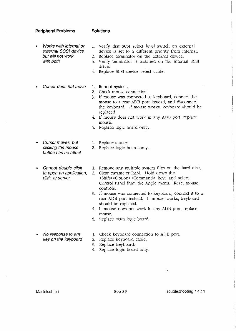
Peripheral Problems
• Works with internal orexternal SCSI devicebut will not workwith both
• Cursor does not move
• Cursor moves, butclicking the mousebutton has no effect
• Cannot double-clickto open an application,disk, or server
• No response to anykey on the keyboard
Solutions
1. Verify that SCSI select level switch on externaldevice is set to a different priority from internal.
2. Replace terminator on the external device.3. Verify terminator is installed on the internal SCSI
drive.4. Replace SCSI device select cable.
1. Reboot system.2. Check mouse connection.3. If mouse was connected to keyboard, connect the
mouse to a rear ADB port instead, and disconnectthe keyboard. If mouse works, keyboard should bereplaced.
4. If mouse does not work in any ADB port, replacemouse.
5. Replace logic board only.
1. Replace mouse.2. Replace logic board only.
1. Remove any multiple system files on the hard disk.2. Clear parameter RAM. Hold down the
<Shift><Option><Command> keys and selectControl Panel from the Apple menu. Reset mousecontrols.
3. If mouse was connected to keyboard, connect it to arear ADB port instead. If mouse works, keyboardshould be replaced.
4. If mouse does not work in any ADB port, replacemouse.
5. Replace main logic board.
1. Check keyboard connection to ADB port.2. Replace keyboard cable.3. Replace keyboard.4. Replace logic board only.
Macintosh IIci Sep 89 Troubleshooting / 4.11

• Known-good l. Make sure System 6.0.4 and Finder 6.1 (or higher)ImageWriter or are used.ImageWriter /I 2. Make sure that the Chooser and the Control Panelwill not print are set correctly.
3. Replace printer interface cable.4. Replace logic board only.
• Known-good l. Make sure System 6.0.4 and Finder 6.1 (or higher)LaserWriter are used.will not print 2. Make sure that the Chooser and the Control Panel
are set correctly.3. Refer to the Networks tab in the Apple Service
Technical Procedures for more information.
4.12 / Troubleshooting Sep 89 Macintosh !Ici

Miscellaneous Problems
• Clicking, chirping,or thumping sound
• System shuts downintermittently
• System intermittentlycrashes or locks up
• No sound fromspeaker
• Clock notrunning
• Systems seems toboot, then message"Finder is old version"displays
Solutions
1. Replace power supply.2. Disconnect HDAj replace if noise disappears.3. Replace logic board only.
1. Make sure air vents on the back side and top of themain unit are kept clear. Thermal protectioncircuitry may shut down the system. After 30 to 40minutes, the system should be OK.
2. Replace power cable.3. Replace power supply.4. Replace logic board only.
1. Make sure System 6.0.4 and Finder 6.1 (or higher)are being used.
2. Make sure software is known-good.3. Replace logic board only.4. Replace SIMMs (refer to "SIMM Verification" in this
section).5. Replace power supply.
1. Verify that the volume setting in the Control Panelis set to 1 or above.
2. Replace speaker.3. Replace logic board only.
1. Replace battery (see "Battery Verification" in thissection).
2. Replace logic board only.
1. Clear parameter RAM by holding down the<Command> <Option> <P> <R> keys and re-bootingthe system. Keep these keys held down, you willhear the normal startup chords and about twoseconds later you will get another chord. Thismeans the parameter RAM has been cleared.
2. Replace logic board only.
Macintosh IIci Sep 89 Troubleshooting / 4.13

o MACINTOSH IIci FLOWCHARTS
Flowchart 1Notes
1. During a normal startup sequence, a mediumpitched soft chord is emitted. If this does nothappen, refer to "Startup and Error Chords" foradditional information. If you cannot interpret thechords, continue with the flowchart.
2. If exchanging the monitor will correct the problem,refer to the Apple High-Res Monochrome Monitor,Apple High-Res RGB Monitor, or the Apple TwoPage Monochrome Monitor Technical Procedures toisolate the monitor problem to the module level.
3. There are two steps to perform when exchangingthe SIMM modules. Refer to "SIMM Verification"for complete instructions on verifying andtroubleshooting the SIMMs.
4. If the known-good SIMMs do not correct theproblem, install the customer's SIMMs on thereplacement logic board.
4.14 / Troubleshooting Sep 89 Macintosh llci

Power on the systemwithout installing adisk.
YES
1. Exchange monitor. (See Note #2.)NO 2. Exchange video cable.
3. Exchange SIMMs. (See Note #3.)4. Exchange logic board only.
(See Note #4.)5. Exchange power supply.
Interpret errorchords. (See
Note #1.)
Power off. If a hard disk is installed,disconnect the SCSI power connector
and cable connector.
Power on the Macintosh llci system withoutinstalling adisk.
YES
1. Exchange SIMMs. (See Note #3.)2. Exchange logic board only.
(See Note #4.)3. Exchange power supply.
Go to Flowchart 3.
Macintosh llci Sep 89 Troubleshooting / 4.15

Flowchart 2Notes
1. Refer to Section 3, Diagnostics, for completeinformation.
2. Refer to the SCSI Hard Disk Drives TechnicalProcedures for complete instructions.
3. Install the customer's SIMMs on the replacementlogic board.
4.16 / Troubleshooting Sep 89 Macintosh \lei

Insert MacTest llci disk.
Shut down and installanother MacTestllci disk.
Power on.
NO
Run MacTestllci. (See Note #1.)
YES
Run Apple Hard Disk Test. (See Note #2.)
Run MacTest IIci. (See Note #1.)
Power off. If ahard disk is installed,remove the SCSI power and cableconnector, or any external drive.
Insert MacTestllci disk. Power on.
Run MacTestllci. (See Note #1.)
NO
Run Apple Hard Disk Test. (See Note #2.)
1. Exchange drive cable.2. Exchange drive.3. Exchange power supply.4. Exchange logic board
only. (See Note #3.)
Macintosh Ilci Sep 89 Troubleshooting / 4.17

Flowchart 3Notes
1. If exchanging the monitor will correct theproblem, refer to the Apple High-Res MonochromeMonitor, Apple High-Res RGB Monitor, or the AppleTwo-Page Monochrome Monitor TechnicalProcedures to isolate the monitor problem to themodule level.
2. There are two steps to perform when exchangingthe SIMM modules. Refer to "SIMM Verification"for complete instructions on verifying andtroubleshooting the SIMMs.
3. Install the customer's SIMMs on the replacementlogic board.
Power on the system.
1. Exchange monilor.(See Nole #1.)
2. Exchange video cable.3. Exchange SIMMs.
(See Nole #2.)4. Exchange logic board.
(See Note #3.)5. Exchange power supply.
4.18/ Troubleshooting
YES
YES
Go to Flowchart 4.
Sep 89
NO
1. Exchange power supply.2. Exchange logic board
only. (See Note #3.)
Go to Flowchart 4.
Macintosh llei

Flowchart 4Notes
1. Refer to Section 3, Diagnostics, for completeinformation.
2. Install the customer's SIMMs on the replacementlogic board.
Flowchart 4
Insert MacTeslllci disk. Power on or reboot.
Run MacTeslllci. (see Nole #1.)
Go 10 Flowchart 5.
Macintosh IIci
NO
Sep 89
1. Exchange drive cable.2. Exchange disk drive.3. Exchange power supply.4. Exchange Idgic board only.
(See Nole #2.)
Troubleshooting / 4.19

FlowchartSNotes
1. Refer to Section 3, Diagnostics, for completeinformation.
2. Refer to SCSI Hard Disk Drives TechnicalProcedures for complete instructions.
3. Install the customer's SIMMs on the replacementlogic board.
4. Customers must always get back the same systemconfigurations they bring in. Refer to "ModuleExchange Information" in this section.
4.20 / Troubleshooting Sep 89 Macintosh llci

Power off. Reconnect theSCSI drive (if installed).
Power on.
Insert MacTestllci disk. Power on.
1. Exchange SCSI power andNO connector cable.
2. Exchange SCSI drive.3. Exchange power supply.4. Exchange logic board only.
(See Note #3.)
YES
Run MacTest llci. (See Note #1.)
Run Apple Hard Disk Test. (See Note #2.)
Customer has correct configuration.(See Note #4.)
Macintosh !Ici
NO
Sep 89
1. Exchange SCSI power andconnector cable.
2. Exchange SCSI drive.3. Exchange power supply.4. Exchange logic board only.
(See Note #3.)
Troubleshooting / 4.21

o SIMM VERIFICAliON
Introduction
Isolating tothe Customer'sSIMMs
The service exchange logic board comes without RAMSIMMs.
The SIMMs installed on the customer's logic board maybe defective. To verify this, you will be removing allof the customer's SIMMs and installing known-goodSIMMs. Mark each known-good SIMM with a dot ofwhite correction fluid or a small sticker. Whatever youuse, be sure it will not come off while you are testing.
1. Remove the top cover.
CAUTION: Before removing the SIMMs, be sure to useproper ESD procedures. If an ESD pad is not available,touch bare metal on the power supply before proceeding.Failure to do so can result in damage to the logic board.
2. Remove the customer's SIMMs, using the SIMMremoval tool. See You Oughta Know for SIMM tooluse.
Note: Record the number and the sizes of theSIMMs. The customer should get the same numberand sizes back! Refer to Section 5, AdditionalProcedures, for information on identifying theSIMMs.
3. Install the four known-good SIMMs in Bank A(Figure 1, #1).
Note: You must use only SIMMs with 80 ns fastpage mode DRAMs. Do not use SIMMs with 100,120, or 150 ns DRAMs. Also, if the customer'sSIMMs are parity SIMMs (9-bit), you must replacethem with know-good parity SIMMs.
4. Switch on the system.
5. Insert the Mac Test IIcx!IIci disk.
If the test boots, run it. Then continue with theappropriate verification procedure.
If the test does not boot, return to the appropriateflowchart.
4.22 / Troubleshooting Sap 89 Macintosh IIci

Verification
Materials Required
FIGURE 1
If the customer has 256K SIMMs or 1 MB SIMMsinstalled, you will need to verify all of them. Use theflowchart and referenced notes on the next two pagesto perform the verification of the SIMMs.
If verifying 256K SIMMs, you will need four knowngood 256K SIMMs.
If verifying 1 MB SIMMs, you will need four knowngood 1 MB SIMMs. .
If verifying 1 MB x 9-bit SIMMs (parity), you will needfour known-good 1 MB x 9-bit SIMMs.
Macintosh IIci Sep 89 Troubleshooting / 4.23

VerificationFlowchartNotes
1. Locate Bank A on the logic board and installthree known-good SIMMs (Figure 1, #1).
2. During a normal startup sequence, a medium-pitchedsoft chord is emitted; then a disk icon with aflashing question mark is displayed on the screen.If either of these things does not happen, refer to"Startup and Error Chords" for additionalinformation.
3. Be sure to set the defective SIMM where it will notbe mixed up with the others.
4. Return to the beginning of the flowchart andperform the same procedure for Bank B(Figure 1, #2).
4.24 / Troubleshooting Sep 89 Macintosh llei

Remove another NOknown-good
SIMM.
Macintosh IIci
Verification Flowchart
Installlhree known-goodSIMMs into Bank A.
(See Note #1.)
Install one of the custome~s SIMMsinto the emply slot in Bank A.
Repeat for Bank B. (See Note #4.)
Sep 89
NOPower off the system.
Remove and set aside thecustomer's bad SIMM.
(See Note #3.)
Troubleshooting / 4.25

o SATTERY VERIFICATION
Introduction There is one lithium battery on the Macintosh lId logicboard, This battery maintains the clock and PRAMwhile the unit is powered off.
WARNING: Lithium batteries, the type used in theMacintosh /lei, have some potential for explosion ifimproperly handled. Follow the procedure below exactlyas written.
Materials Required Voltmeter
VerificationProcedure
To check the lithium battery with a voltmeter,
1. Be sure power is off. Then remove the top lid.
2. Remove the power supply.
3. Remove the drive carrier.
4. Set the voltmeter range to measure 10 volts DC.
5. Touch and hold the positive probe of the voltmeterto the positive side of the battery (Figure 2, #1) .
..",·r:
/
.... ~~')J~,. ••• (.:..;;:.. • ...w ••,
<:;;>::::~~>..:-... .....~.~.
'. . ..•...' .....:.r.':' ,,1Y'd' ~""'l
". '" ..'i .., ..' " (~~...?p~1f~~' :&4;~i/~"'.'. '. <f.~·;vr'· ,4;:< /~rt-.. Ai<:! ..
1"''<' 4/ ":;':;f~' . b~<'{;f::···/ "'~" A·' ..~,.,-r' ,".A;;" ../.,(>1:V"';-'/'/ '. ~..';f;'/.'1f(' d?/A~r ./' ";/e%: t·4?';{(}J!,
'<~1-;{&~iY~: ~, .. r.'.5.'I' 'l:'~~ "
:"":;-'" .,41'./" ~"'''::«7/
'.,;v"
FIGURE 2
4.26 / Troubleshooting Sep 89 Macintosh IIci

4. Touch and hold the ground probe of the voltmeter tothe negative side of the battery.
5. The reading for a good battery should be above 2.8volts. If the battery falls below 2.8 volts, replace it.Refer to Section 5, Additional Procedures, forreplacement instructions.
Macintosh IIci Sep 89 Troubleshooting / 4.27


Ii Apple Technical Procedures
Macintosh IIci
section 5 - Additional Procedures
o CONTENTS
5.3 Battery Replacement5.3 Storage and Handling5.3 Disposal5.6 Logic Board RAM Identification and Upgrades5.6 Introduction5.6 Identification5.7 Upgrades
Note: If a step is underlined, instructions for that stepcan be found in Section 2, Take-Apart.
Macintosh !Ici Sep 89 Additional Procedures / 5.1

o SATIERY REPLACEMENT
WARNING: A lithium battery, the type used in theMacintosh /lei, has some potential for explosion ifimproperly handled.
Storage andHandling
Disposal
Take the following precautions when storing andhandling lithium batteries:
• When Apple's lithium battery is shipped to you, it issealed in an individual zip-lock wrapper. When youreceive it, check to make sure the wrapper is intact.If it is not, mend the wrapper before you store thebattery.
• Store the battery in the packaging in which youreceived it.
• The storage area for lithium batteries should bewell marked, and access to the area should berestricted.
• Never store batteries together where they mayshort together or explode.
Lithium batteries cannot be recharged and will requiredisposal when "dead." You cannot throw them away asyou would other batteries: lithium is water-reactive, inaddition to being potentially explosive. Lithiumbatteries must be disposed of as hazardous waste.
WARNING: "Dead" lithium batteries are consideredhazardous waste and must be returned to Apple in theiroriginal packaging for disposal following EPA guidelines.
Because of this hazard, Apple recommends the followingcourse of action:
After removing a "dead" battery from a board, place thebattery in the zip-lock wrapper and original packagingfrom which the replacement battery was taken. Markthe battery DEAD and return it to Apple, where it willbe disposed of following EPA guidelines.
Macintosh /Ici Sep 89 Additional Procedures / 5.3

Materials Required
Remove
The long-life lithium battery in the Macintosh lIcishould serve many years. Refer to Section 4,Troubleshooting, to check the condition of the battery.If the battery should fail for some reason, replace itaccording to the following procedure.
Grounded workbench and wriststrap
CAUTION: Use ESD precautions before removing orreplacing the battery. Failure to do so may result in logicboard failure.
1. Remove the logic board.
2. Locate the battery holder (Figure 1, #1) and battery(Figure 1, #2) toward the front of the logic board.
FIGURE 1
5.4 / Additional Procedures Sep 89 Macintosh Ilci

Replace
3. On one side of the battery holder, insert a small(1/8") flat-blade screwdriver into the top(Figure 1, #3) and gently push the screwdriverdown until the side tab (Figure 1, #4) pushes out.The battery holder cover will come loose; do thesame on the other end and remove the cover fromthe holder.
4. Grasp the battery between the thumb andforefinger and lift out the battery.
1. Insert the new battery so the positive side of thebattery is inserted into the positive-marked side ofthe holder (Figure 1, #5), the side away from theLED.
CAUTION: Be sure the positive side of the battery is in thecorrect location (see Figure 1). An incorrectly placedbattery can damage the logic board.
2. Replace the holder cover.
3. Replace the logic board.
4. Set the clock using the Control Panel.
Macintosh IIci Sep 89 Additional Procedures / 5.5

o LOGIC BOARD RAM IDENTIFICATION AND UPGRADES
Introduction
Identification
256K SIMMs
RAM for the Macintosh IIci is provided in packagesknown as Single In-line Memory Modules (SIMMs). ASIMM is a circuit board 3.5-inches long and from 5/8inch to l-inch high, with two or eight (nine if paritychip is present) memory chips. The memory chips maybe surface-mounted, or they may be mounted throughthe board. Each SIMM board has contacts on one edgethat fit into sockets on the logic board.
The SIMMs are available with two sizes of RAM, 256Kand 1 MB, and come in a few configurations that can beused interchangeably.
CAUTION: SIMMs are very susceptible to damage fromESD and skin acid. Handle SIMMs only by the edges.
Note: When you are removing SIMMs from the logicboard, use the SIMM removal tool. Instructions forusing this tool are located in You Oughta Know.
The 256K SO] (Single Out-line ]Lead) SIMMs(Figure 2) contain two surface-mounted ICs. Each IC hasten pins (or legs) on each of two sides.
FIGURE 2
IMPORTANT: You must use BOns fast page mode SIMMson the Macintosh /lei. The 100, 120, and 150ns SIMMswill cause serious timing problems.
256K SIMMs are available in several speeds. However,only the 80ns SIMMs are suitable for the MacintoshIIci. You can identify a 80ns SIMM by the number 8after the vendor's part number printed on the top ofeach chip. Only the 256K SIMMs that have two 1 MBchips (256K x 4 x 2) have been Apple qualified.
5.6/ Additional Procedures Sep 89 Macintosh Ilci

1 MBSIMMs
Upgrade,s
The 1 MB SIMMs come in two configurations:
• 1 MB sOJ SIMM (Figure 3, #1)The 1 MB SOJ (Single Out-line JLead) SIMMcontains eight surface-mounted ICs. Each IC has tenlegs on each of two sides.
• 1 MB x 9-bit SOJ SIMM (Figure 3, #2)The 1 MB SOJ (Single Out-line JLead) parity SIMMcontains nine surface-mounted ICs. Each IC has tenlegs on each of two sides.
°00000000°000000000000000000000000000000
°000000000 0
000000000000000000000000000000
FIGURE 3
Various RAM upgrades are possible on the MacintoshIIci, depending on the number and size of the SIMMsthat you install on the logic board.
For installation purposes, two banks of SIMM socketsare located on the logic board and are labeled Bank A(Figure 4, #1) and Bank B (Figure 4, #2). Each bankcontains four slots, which are grouped into twos. Allfour slots within a bank must be filled with SIMMs ofthe same RAM size.
Each bank may contain either no RAM or four 256K,1 MB, 4 MB, or 16 MB SIMMs. (The 4 MB and 16 MBSIMMs can be used when available.) But at least one ofthe banks must have RAM in it.
If you are using built-in video, you must 'have SIMMs inbank A, because the built-in video uses bank A forvideo framing. If you are using a video card, then usingbank A is optional.
1
2
Macintosh IIci Sep 89 Additional Procedures / 5.7

If the unit is a parity system, you can upgrade to morememory, but you must use the parity SIMMs (l MB x 9bit SO] SIMMs) to do so. If parity SIMMs are not used,the parity function will be disabled.
FIGURE 4
5.8 / Additional Procedures Sep 89 Macintosh Ilci

The following chart summarizes the configurations thatthe Macintosh lIci supports:
RAM
1 MB
2 MB
4 MB
5 MB
8 MB
4 MBParity
8 MBParity
Bank A
Four 256K SIMMs
Empty·
Four 256K SIMMs
Four 1 MB SIMMs
Empty·
Four 1 MB SIMMs
Four 256K SIMMs
Four 1 MB SIMMs
Four 1 MBparity SIMMs
Empty·
Four 1 MBparity SIMMs
BankB
Empty
Four 256K SIMMs
Four 256K SIMMs
Empty
Four 1 MB SIMMs
Four 256K SIMMs
Four 1 MB SIMMs
Four 1 MB SIMMs
Empty
Four 1 MBparity SIMMs
Four 1 MBparity SIMMs
CAUTION: Other configurations, such as a single SIMM ora pair of different-size SIMMs, will not function correctly.
• DRAM is needed in bank A when built-in video is used.
Macintosh IIci Sep 89 Additional Procedures / 5.9


o CONTENTS
• Apple Technical Procedures
Macintosh Uci
Illustrated Parts List
IPL.3 Macintosh IIci-System ExplodedView (Figure 1)
IPL.5 Macintosh IIci-Logic Board (Figure 2)IPL.5 Macintosh IIci-Logic Board with Parity
(Figure 3)IPL.7 Keyboard (Figure 4)IPL.9 Extended Keyboard (Figure 5)IPL.ll ISO Keyboard (Figure 6)IPL.13 Mouse (Figure 7)
The figures and lists in this section include all pieceparts that can be purchased separately from Apple forthe Macintosh IIci, along with their part numbers.These are the only parts available from Apple. Refer toyour Apple Service Programs manual for prices.
Macintosh IIci Sep 89 Illustrated Parts List / IPL.1

23
IPL.2/ Illustrated Parts List
II
~
~FIGURE 1
Sep 89
2
Macintosh IIci
12
./

o MACINTOSH IIci-5YSTEM EXPLODED VIEW (Figure 1)
1
23456789
101112131415161718192021222324
2526
Part No.
416-1412
590-0512590-0609815-5071444-6104982-0023661-0467815-6033661-0532661-0583630-5662815-6032590-0380865-0026815-6036590-0506844-0018805-0961815-6034661-0474590-0607815-6030590-5503815-6031661-0373661-0464661-0600805-5078810-6028
Description
Screw, M 3.5 x .6 x 8 (Top Cover, HDA Bracket toBottom Case)
Cable, Internal HDA PowerCable, Internal HDABracket, Power Supply FanScrew, 6-32 x .250 (HDA to HDA Bracket)Power Supply FanPower Supply with FanOn-Off ButtonLogic BoardLogic Board, ParityBottom CaseLight Pipe, Power OnCable, Power AC (smoke)Rubber FeetLight Pipe, HDACable, HDA LED (amber)Screw, Socket, Phillips 0.4 MB Mechanism)Shield, Internal 1.4 MB MechanismReset/Interrupt Switch1.4 MB Mechanism, Apple FDHDCable, Internal 1.4 MB MechanismDrive CarrierSpeakerSpeaker BracketHDA, Internal 3.5 SCSI, 20 MBHDA, Internal 3.5 SCSI, 40 MBHDA, Internal 3.5 SCSI, 80 MBBracket, HDA, MountingTop Cover
Macintosh !Ici Sep 89 Illustrated Parts List / IPL.3

3
FIGURE 2
FIGURE 3
IPL.4/ Illustrated Parts List Sep 89 Macintosh IIci

o MACINTOSH IIci-LOGIC BOARD (Figure 2)
Item Part No. Description
661-0532 Logic Board1 742-0011 Lithium Battery2 520-0344 Battery Holder Cover3 661-0519 SIMM, 256K x 4, 80 ns
661-0520 SIMM, 1 MB, 80 ns
o MACINTOSH IIci-LOGIC BOARD WITH PARITY (Figure 3)
123
Macintosh IIci
part No.
661-0583742-0011520-034466,1-0546
Description
Logic Board, ParityLithium BatteryBattery Holder CoverSIMM, 1 MB x 9, 80 ns, Parity
Sep 89 Illustrated Parts List / IPL.5

3=w>IZo0::u..
IPL.6/ Illustrated Parts List Sep 89 Macintosh Ilci

o KEYBOARD (Figure 4)
123456
Part No.
661-0383c661-0383£661-0383815-1016658-7011076-0209815-1017970-1263590-0361590-0152
Description
Apple KeyboardApple Keyboard, French CanadianApple Keyboard, SpanishTop CaseKey Cap SetKeyswitch Set, ADB Keyboard (Set of 10)Bottom CaseAlps Locking KeyswitchKeyboard Cable, 1 meterKeyboard Cable, 2 meter
Macintosh llei Sep 89 Illustrated Parts List / IPL.7

· :.:.;.:.;: .
......
~:>~oa:u..
IPL.8/ Illustrated Parts List Sep 89 Macintosh Ilci

o EXTENDED KEYBOARD (Figure 5)
123456
Part No.
661-0384c661-0384D661-0384E661-0384F661-0384T661-0384815-1018658-7010076-0209815-1019970-1263590-0361
Description
Apple Extended KeyboardApple Extended Keyboard, French CanadianApple Extended Keyboard, GermanApple Extended Keyboard, SpanishApple Extended Keyboard, FrenchApple Extended Keyboard, ItalianTop CaseKey Cap SetKeyswitch Set, ADB Keyboard (Set of 10)Bottom CaseAlps Locking KeyswitchKeyboard Cable, 1 meter
Macintosh IIci Sep 89 Illustrated Parts List / IPL.9

1PL.1 0 / Illustrated Parts List Sep 89 Macintosh IIci

o ISO KEYBOARD (Figure 6)
Macintosh Ilci
Part No.
D661-0454F661-0454T661-0454
Description
Keyboard, Apple ISO, GermanKeyboard, Apple ISO, FrenchKeyboard, Apple ISO, Italian
Sep 89 Illustrated Parts List! IPL.11

FIGURE 7
IPL.12/ Illustrated Parts List Sep 89 Macintosh IIci

o MOUSE (Figure 7)
123
Part No.
661-0479815-1135815-1136
Description
ADB Mouse (replacing part number 661-0338)Mouse Ball (for part number 661-0479)Retainer, ADB Mouse (for part number 661-0479)
Note: The ADB Mouse (part number 661-0338) has been replaced by partnumber 661-0479. Below is the list of parts for part number 661-0338.
2
3
Part No.
699-8001699-8038076-0231815-0816
Description
Mouse Ball (25.4 mm dia)Mouse Ball (21.9 mm dia)Retainer, ADB Mouse (38 mm dia)Retainer, ADB Mouse (34 mm dia)
Macintosh IIci Sep 89 Illustrated Parts List! IPL.13
