technical guidelines building over and adjacent to pipe assets
TRANSCRIPT

Building over and adjacent to pipe assets
Technical guidelines
August 2021

Cover page: Better planning can prevent damage from heavy machinery working near pipelines.
SW269 08/21

Contents
1 Building over and adjacent 41.1 Overview 4
1.2 What are building over and adjacent (BOA) works? 4
1.3 What are Sydney Water pipe assets? 4
1.4 What are building works? 5
1.5 What pipes can you build over? 5
1.6 What pipes can you build adjacent to? 5
1.7 What is a service location diagram? 5
1.8 What is a service protection report? 5
1.9 What are building plans? 5
1.10 What is a specialist engineering assessment? 6
1.11 What are temporary protection works? 6
1.12 What are permanent protection works? 6
1.13 What is a monitoring plan? 6
1.14 What is a contingency plan? 6
1.15 Whatisthezoneofinfluence? 6
2 Protecting pipe assets 92.1 Free and full access 9
2.2 Understanding the pipe asset 9
2.3 Temporary and permanent protection works 10
2.4 Maintenance-free concrete encasement 10
2.5 Reinforced concrete encasement 11
2.6 Lining 11
2.7 Bridging slab 11
2.8 Protecting pipe assets from construction plant loadings 12
2.9 Clearances between underground services 15

3 BOA diagrams 173.1 General 17
3.2 Design responsibility 17
3.3 Acceptance 17
Diagram 1 – Demolition works 18
Diagram 2 – Building next to easements 19
Diagram 3 – Pavements on residential lots 20
Diagram 4 – Pavements on commercial or industrial lots 21
Diagram 5 – Planting trees 22
Diagram 6 – Lightweight structures over reticulation sewers 23
Diagram 7 – Working space and clearances around wastewater (sewer) maintenance structures 24
Diagram 8 – Building near free-standing ventshafts 25
Diagram 9 – Paling, chain-link and palisade fences 26
Diagram 10 – Short masonry walls 27
Diagram 11 – Retaining walls 28
Diagram 12 – Domestic stormwater absorption trenches, and rain gardens 29
Diagram 13 – Domestic swimming pools / water tanks adjacent 30
Diagram 14 – Domestic swimming pools / water tanks over 31
Diagram 15 – Residential dwelling slabs and footings 32
Diagram16–Buildingfoundationsbelowthezoneofinfluence (building over) 33
Diagram16.1–Buildingfoundationsbelowthezoneofinfluence (building adjacent) 34
Diagram 17 – Building foundations on piles (building over) 35
Diagram 17.1 – Building foundations on piles (building adjacent) 36
Diagram 18 – Small temporary unsupported excavations 37
Diagram 19 – Small supported excavations 38
Diagram 20 – Large excavations 39
Diagram 21 – Dewatering 40
4 Contact us 41

| 3Technical guidelines – Building over and adjacent to pipe assets
How to use these technical guidelines
Building over and adjacentSection 1 explains what is covered by these guidelines, what are building over and adjacent (BOA) works, and details important terms used in the document.
Protecting pipe assetsSection 2 explains the notion of free and full access, and describes temporary and permanent works usually used to protect pipe assets. It also provides general guidance on protecting our pipe assets from construction plant loadings.
BOA diagramsSection 3 contains diagrams illustrating common situations where works are built over and adjacent to ourpipeassets.Ifyourproposedworksfitthedepictedsituation,theoutlinedtechnicalrequirementswill apply. More than one diagram may apply to your case. If your works do not fall under any of the situations,you’llrequireaSpecialistEngineeringAssessment.ConsultSydneyWaterearlyandworkwith us to avoid damaging our assets.
AcceptanceThis document does not tell you how to obtain acceptance from Sydney Water for your proposed works. Our Land development guide and Asset adjustment and protection manual will guide you through the procedure.Youcanfindthesedocumentsonourwebsite.

4 | Technical guidelines – Building over and adjacent to pipe assets
1 Building over and adjacent
1.1 OverviewWhen you build over, adjacent, close to or under Sydney Water pipe assets, your work must not:
• obstruct full and free access to our assets
• cause physical damage to our assets
• weaken our assets leading to future damage
• increase the likelihood of a hazardous situation (for example, induced voltages onto our pipelines).
More information can be found in our Policy - Building over or adjacent to Sydney Water assets.
The following guidelines in this document outlinetherequirementsthatapplyincommonbuilding work. You may use these guidelines to understand whether your proposed building work is likely to cause adverse impacts. If you don’t understand some of the complex technical issues, seek appropriate advice.
Our stormwater pipes and channels are not covered by this document. For information on stormwater assets, refer to the Guidelines for building over or adjacent to Sydney Water stormwater assets.
In addition to complying with the technical requirements,youmustalso:
• obtainanystipulatedletterofrequirements
• complywiththerequirementsset
• exercise due care when you build.
Our Land development guide and Asset adjustment and protection manual will guide youthroughtheprocedure.Youcanfindthesedocuments on our website.
These guidelines are to help you and your professional advisors, including architects, engineers and designers, to better plan and construct works that are near to our assets.
If you cause adverse impact to any of our assets, you’ll have to pay the costs of returning them to serviceable condition.
1.2 What are building over and adjacent (BOA) works?
Any building works likely to adversely impact on our pipe assets are regarded as ‘building over or adjacent to’ (BOA) works. Building over and adjacent means over, under, or next to.
1.3 What are Sydney Water pipe assets?
Our pipe assets are buried or above-ground pipes and conduits of various size, shape and form. They were made of a variety of materials common at the time of construction. Some date back to the 19th century. Some pipes operate under internal pressure while others do not.
Some of our critical pipe assets are protected by acquiredeasementsoverland,butwehavemanycritical assets that don’t have easements. Whether or not there’s an easement, you must give due care to protect our assets and ensure access for our operation and maintenance purposes.
1.3.1 What are Sydney Water maintenance structures?
Our maintenance structures are the means by which we access our pipe assets for maintenance and repair. They vary in size and shape and usually have an access cover at ground level. Wastewater (sewer) maintenance structures can include maintenance holes, maintenance chambers, maintenance shafts, rodding points and lamp holes.
For clarity, this guide shows one type of maintenance hole to represent maintenance structures in general.

| 5Technical guidelines – Building over and adjacent to pipe assets
1.4 What are building works?Anynewbuildingsandstructures,ormodificationto existing buildings or structures, and any work that changes the current form and shape of the ground are ‘building works’.
Building works may include residential dwellings, commercial and industrial buildings, swimming pools, carports, non-habitable sheds, decks, fences, retaining walls, driveways, pavement, drains, landscaping, roads, utilities, infrastructure works and temporary works.
Demolition of disused buildings and structures, temporary works, excavation and boring are also building works.
You may need to consider the impacts of future excavation to our asset, or a possible failure of our asset, on your temporary or permanent works and plan accordingly. Relocation of your works or our asset may be a preferred alternative.
1.5 What pipes can you build over?
We’ll consider allowing you to build certain structures over our reticulation sewers with diameters 300 mm and smaller.
Building over or adjacent to larger sewers with diameters up to 750 mm is not preferred. If you wish to build over these pipes, talk to us early as we may impose substantial restrictions and you’ll need a specialist engineering assessment.
1.5.1 What pipes can’t you build over?
We won’t allow you to build over the following assets:
• Pressure pipes for water supply and wastewater (sewerage), including pressure and vacuum sewer pipes or stormwater pressure pipes.
• Wastewater (sewer) property connection points and maintenance structures.
• Non-pressure wastewater (sewer) pipes thathavediametersequaltoorgreaterthan750 mm, and other critical assets such as tunnels, oviforms and our heritage listed assets.
• Easements.
1.6 What pipes can you build adjacent to?
We’ll allow you to build adjacent to our assets and easements if you:
• satisfy us that you’ll do all the necessary temporaryandpermanentworksrequiredtoprotect the assets from damage
• demonstrate that your development won’t impede access to the assets for their maintenance, repair or replacement.
1.7 What is a service location diagram?
A service location diagram shows our pipe assets, but only indicates the presence of our pipes. It doesn’t pinpoint the exact physical location.
You can purchase the diagram through Sydney Water Tap in on our website. It can also be obtained through the national referral service Dial Before You Dig.
1.8 What is a service protection report?
Aserviceprotectionreportidentifiesandpegsout on-site Sydney Water assets. It enables the accurate plotting of these assets onto your building plans. Only Sydney Water listed Service Protection Reporters can prepare these reports. Youcanfindthelistonourwebsite.
1.9 What are building plans?Your building plans must describe in detail your proposed works and the location of Sydney Water pipe assets. If necessary, plans showing the extent and method of supporting excavation in the ground should be included. The plans may also includetheconstructionsequence,dewateringortemporaryworksrequiredduringconstruction.

6 | Technical guidelines – Building over and adjacent to pipe assets
1.10 What is a specialist engineering assessment?
Where directed by these guidelines or where yourworksdonotmeettherequirementsshownin these guidelines, or involves building over or adjacent to assets greater than 300 mm, a specialistengineeringassessmentwillberequiredand your works may need to be amended. Refer to Sydney Water Procedure - Specialist Engineering Assessment (SEA)forspecificrequirements.
All specialist engineering assessment submissions must be prepared by engineers meeting our Engineering Competency Standard. Some submissionswillrequireindependentverification.All submissions will involve a report and a completed SEA Submission Checklist to be submittedforouracceptance.Youcanfindthesedocuments on our website.
1.11 What are temporary protection works?
Temporaryprotectionworksarethoserequiredtoprotect our pipe assets during your construction works. They may include supports, barriers or other construction control measures.
1.12 What are permanent protection works?
Permanentprotectionworksarethoserequiredto be constructed to protect our pipe assets on a permanent basis. They may include strengthening or rehabilitation works and will remain after construction is complete.
1.13 What is a monitoring plan?
A monitoring plan outlines how you will monitor the impact of your building works on our pipe assets. Your plan must contain warning thresholds to allow enough time to implement actions to avoid damage or failure of our assets. Your plan may also include dilapidation surveys.
1.14 What is a contingency plan?
A contingency plan outlines the control measures thatcanreducetheconsequencesifyourworkcauses our pipe asset to fail or disrupts our service to customers.
The plan may show alternative construction systems, provide for cut-off barriers or alternative constructionequipmentorchangethesequenceof work. It may also include providing emergency resources or repair materials, such as special pipe couplings or clamps.
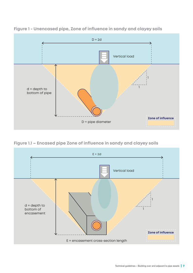
1.15 What is the zone of influence?
Thezoneofinfluence(ZOI)forexternalloadingis the notional envelope within which an external vertical load would exert stress on a pipe or structure (Figures 1, 1.1 and 1.2). The zone is definedbythelinesfromthebottomprojectionof the pipe or structure extending upwards at an angle of 45° to the ground surface. Where the pipe is currently concrete encased or will be encased, these lines extend from the bottom edge of the encasement.The stress created in the soil by a vertical load on the ground surface lessens with depth. So, pipes buried deeper are generally less affected than shallower ones.TheZOIforotherimpactssuchasexcavationforyour works and dewatering near our pipes are considered in diagrams 18 – 21.
TheZOIforimpactsonyourworksduetopossible future excavation of our pipes are considered in diagrams 13, 16.1 and 17.1.
| 7Technical guidelines – Building over and adjacent to pipe assets
Figure 1 - Unencased pipe, Zone of influence in sandy and clayey soils
D + 2d
d = depth to bottom of pipe
D = pipe diameter
Vertical load
Zone of influence
1
1
Figure 1.1 – Encased pipe Zone of influence in sandy and clayey soils
E + 2d
d = depth to bottom of encasement
Vertical load
Zone of influence
1
1
E = encasement cross-section length

8 | Technical guidelines – Building over and adjacent to pipe assets
Figure 1.2 – Structure Zone of influence in sandy and clayey soils
S + 2d
d = depth to bottom of structure
Vertical load
Zone of influence
1
1
S = width of structure base

| 9Technical guidelines – Building over and adjacent to pipe assets
2 Protecting pipe assets
2.1 Free and full access
2.1.1 General We must be able to reach our pipe assets. We need access to and working space around surface fittingsandaccesspointsforroutineoperationandmaintenance.Wemayalsorequireconstructionand excavation space for repair or renewal.
Free access is safe 24-hour access so we can manage incidents without delay. If your building works are likely to restrict free access and impede emergency response, you’ll need to make appropriate alternative access arrangements that we must agree with and accept.
Full access includes safe passageway for appropriateplantandequipment.
Access through foyers, habitable spaces and staircase is not considered to be safe, free and full access.
2.1.2 Reticulation wastewater (sewer) maintenance structures
You must not build over wastewater (sewer) maintenance structures.
For us to access reticulation wastewater (sewer) maintenance structures, we need an unobstructed passageway with a minimum width of 900 mm and minimum clear headroom of 2.4 m. A maintenance vehicle must be able to park not more than 50 m from the maintenance structures.
To set a tripod at a maintenance hole, we need a working space of at least 1 m around the rim of the cover with minimum headroom of 2.4 m above. For a maintenance shaft or maintenance chamber, the working space may be reduced to 600 mm around the rim of the cover.
2.1.3 Other pipe assets Operating headroom clearance and working spacerequirementsforotherpipeassetsvaryaccording to asset type. It’s important to consult SydneyWaterearlytoobtainourspecificrequirementsforyoursite.
Generally,werequireminimumheadroomof 2.4 m above pipe access points.
2.2 Understanding the pipe asset
Additional loadings, vibration or ground movement will increase stress in a pipe asset. This may compromise the built-in safety factor, shortening service life and durability in the long-term. In severe cases, the increased stress could damage or collapse the pipe.
The ability to resist new loads depends on the type and existing service condition of the pipe asset. Older pipes with defects are more prone to damage than new ones. Lead-jointed cast iron pipes are vulnerable to damage by small ground movement. Wastewater (sewer) pipes corrode internally more severely than other pipes because of gases inside the pipe. Aggressive soil and groundwater attack the external protective coating of buried pipes.
If necessary, the service condition of an existing pipe asset is usually assessed by:
• CCTV inspection
• opening up the ground for visual inspection.
2.2.1 Pressure pipesPressure pipes for water, wastewater (sewer) and some stormwater have large stored energy. Atcertainfittingsandbends,theseforcesarebalanced by thrust or anchor blocks in the ground.Takecaretofindoutifthesearepresentif building or excavating near them and take precautions to ensure they’re not disturbed.

10 | Technical guidelines – Building over and adjacent to pipe assets
2.3 Temporary and permanent protection worksWhen BOA works are affecting our pipe asset, temporary or permanent protection works will be required.Ifpipeassetsarebuiltoveroradjacentobstructingfreeandfullaccess,theymayneedtobestrengthened or made more robust.
Temporary protection methods may include erecting temporary barriers, adapting construction methodology, and controlling vibration and ground movement.
Permanent protection methods are typically relocation of the asset away from building works, concrete encasement, internal lining and bridging slabs. The table below explains when these methods are used.
Purpose Concrete encasement
Lining – non-structural
Lining – structural
Bridging slab
Maintenance-free
To provide a more robust installation to reduce likelihood of damage ü
Strengthening To provide additional structural capacity to the pipe to resist additional external loading
üRehabilitation To rehabilitate a
deteriorated pipe to stop internal corrosion and prevent soil/water entering through broken joints
ü ü
Load isolation To isolate the pipe from excessive loading ü
2.4 Maintenance-free concrete encasement
Encasingapipeinconcretewillmaketheinstallation more robust. It provides additional protection to the pipe from unexpected external load and movement, reducing the risk of damage andconsequentlytheneedforrepairs.However,visual inspection and future access to the pipe will be permanently impeded. So, it must be used with caution.
Examplesofmaintenance-freeconcreteencasement are:
• at major road, rail, creek or stormwater crossings
• when a structure or part of a structure is built directly above the pipe and is impeding future open-cut excavation access to the pipe.
Encasementmaybeusedforsteelpipes,castironorductileironpipes,PVC,PE,GRPandclaypipes.Inflexible-jointedpressuremains,theencasement must not cover more than two rubber ring joints. At both ends of the encasement, shortrockerpipeswithflexiblejointsmustbeincorporated at the terminal faces.
Concrete encasement is not appropriate for:
• mechanicaljointcouplings,flangedjointsandlead joints
• pipes with external corrosion or damage. Replacementofpipesisrequiredbeforeencasement
• cast iron and ductile iron pipes in non-pressure wastewater (sewer) situations. Replacement of pipesisrequiredbeforeencasement
• cement mortar jointed clay pipes. Replacement ofpipesisrequiredbeforeencasement

| 11Technical guidelines – Building over and adjacent to pipe assets
• pipes in poor or unstable ground or mine subsidence areas
• deep pipes
• pipes in a deteriorated state.
Maintenance-free concrete encasement takes the form of an articulated plain concrete surround for non-pressure wastewater (sewer) pipes in good ground conditions where external loads are not excessive. To ensure full compaction of concrete underthepipe,youmustfirstplaceconcreteonone side and vibrate it until it emerges from under the pipe on the other side.
Reinforcementisrequiredformaintenance-free encasement for large diameter pipes and pressure pipes to control cracking of the concrete.
2.5 Reinforced concrete encasement
When additional loads are imposed on a pipe beyond its capacity, you may use reinforced concrete encasement to strengthen the installation (Figure 2). This must be designed by a competent structural engineer.
Figure 2 - Reinforced concrete encasement
2.6 LiningYou may install an internal lining to prevent deterioration of the pipe from corrosion. Lining mayalsohelppreventexfiltration,infiltrationofgroundwater and migration of soils into the pipe. For small pipes it may be possible to install a structural lining to take additional loading. This must be designed by a competent structural engineer.
It’s common to install linings using trenchless techniques,suchassliplining,cured-in-placelining and spirally wound liners for the whole pipe length between maintenance holes.You’ll need a specialist engineering assessment if proposing lining.
2.7 Bridging slabYou may use a reinforced concrete bridging slab to protect the buried non-pressure pipe assets from additional loading. The slab spans over the pipe for a distance determined by the zone of influenceofthepipeasshowninFigure 3. Place a layer of compressible material underneath the span of the slab.
The slab may often be made of precast units for removal. A competent structural engineer must prepare design and construction details.

12 | Technical guidelines – Building over and adjacent to pipe assets
Figure 3 - Reinforced concrete bridging slab
Length, size and weight determined by structural engineer
RC bridging slab 50 mmcompressiblematerial
Zone of influence
2.8 Protecting pipe assets from construction plant loadings
Buried pipe assets can be subject to construction plant loading in construction sites. The pipe relies on the cover of soil above the crown to protect it from damage.
You must locate and peg out the position and line of our pipe assets on-site before starting any site work.Exerciseextremecareduringconstruction.If you have any doubt on the service or physical condition of any pipe asset, contact us as soon as possible.
Shallow pipes
For pipes with less than 0.45 m cover, no construction plant may pass or be positioned withinthezoneofinfluence(Figure 4). If you need to traverse the pipe, you must put protection measures in place. You must complete a specialist engineering assessment and prepare a work method statement for our acceptance.For pipes with soil cover more than 0.45 m, light construction plants such as forklifts, small
excavators, wheel loaders and the like are usually allowed (Figure 5). For non-reticulation pipes, you must prepare a specialist engineering assessment for our acceptance.
Deep pipes
Generally, we permit construction plant for pipes withsoilcoverover1.2m.However,theseplantsare limited to those with individual wheel load not exceeding 80 kN, or axle load not exceeding 160 kN (Figure 6).Examplesoftheseplantsareregistered vehicles permitted on public roads and construction plant under 25 tonnes.
For non-reticulation pipes, you must prepare a specialist engineering assessment and a work method statement for our acceptance.
Heavy plant
Heavyconstructionplantmustnottraversepipesorbepositionedwithinthezoneofinfluence.Heavyconstructionplantincludespilingrigs,cranes, rollers and the like (Figure 7).
If you need to place heavy construction plant above our pipe assets, you must prepare a specialist engineering assessment and a work method statement for our acceptance.

| 13Technical guidelines – Building over and adjacent to pipe assets
Figure 4 - Construction plant not permitted within zone of influence for shallow pipes
Note: Pipe asset is assumed to be in a soil trench and is in reasonable condition.Poor and unstable ground not applicable.
Soil cover lessthan 450 mm
Zone of influence
Figure 5 - Light construction plant permitted within zone of influence
Note: Pipe asset is assumed to be in a soil trench and is in reasonable condition.Poor and unstable ground not applicable.
Light construction(excluding rollers)
Grossoperatingweight5 tonnes 450 mm10 tonnes 750 mm
Minimumsoil cover
Zone of influence

14 | Technical guidelines – Building over and adjacent to pipe assets
Figure 6 - Construction plant permitted within zone of influence for deep pipes
Note: Pipe asset is assumed to be in a soil trench and is in reasonable condition.Poor and unstable ground not applicable.
Soil cover morethan 1.2 m
Construction plant up to 25 tonnes(excluding rollers)
Wheel load not exceeding 80 kN,or axle load not exceeding 160 kN.
Zone of influence
Figure 7 - Heavy construction plant not permitted within zone of influence
Note: If heavy construction plant needs to traverse or be placed within the zone of influence, prepare a specialist engineering assessment and work method statement for acceptance by us.
Zone of influence

| 15Technical guidelines – Building over and adjacent to pipe assets
2.9 Clearances between underground services
Where services are proposed near our underground pipes, minimum clearances apply, as shown in the clearances tables below.
These are minimum clearances between our existing buried pipes and new utility services to be installed by conventional trench methods. For trenchless methods, a specialist engineering assessment(SEA)isrequiredandmayresultingreater clearances being needed. Clearances
between our existing buried pipes and new water or wastewater (sewer) services to be installed are addressed in our codes for the installation of those services.
Our buried pipes may also have appurtenances such as valves, hydrants, and cubicles that we need to access and operate at ground level and sometimes replace. A minimum of 2.4 m vertical and 2 m horizontal clearance above ground is requiredbetweentheseappurtenancesandbuildings,trafficlightkiosks,carchargingstations,power poles, bus shelters and other structures.
Horizontal clearance
Utility
Pressure water pipes ≤DN 200 / >DN 200 to ≤DN 375
Non-pressure wastewater (sewer) pipes ≤DN 300
Pressure and vacuum wastewater (sewer) pipes ≤DN 200
Gaspipes≤DN200 3007 / 600 300 3007
Gas pipes >DN200 500 / 600 500 500Telecommunication conduits and cables 3007 / 600 300 3007
Protected low and high voltage electricity conduits and cables 10008 5008 10008
Extrahighvoltageelectricityconduitsandcables SEA8 SEA8 SEA8
Stormwater pipes 300 / 600 300 300Kerbs 3003 / 6003 N/A 3003
Vertical clearance
Utility
Pressure water pipes ≤DN 375
Non-pressure wastewater (sewer) pipes ≤DN 300
Pressure and vacuum wastewater (sewer) pipes ≤DN 200
Gaspipes≤DN200 300 300 300Gas pipes >DN200 500 500 500Telecommunication conduits and cables 300 300 300Protected low and high voltage electricity conduits and cables 6008 3008 6008
Extrahighvoltageelectricityconduitsandcables SEA8 SEA8 SEA8
Stormwater pipes 300 300 300Kerbs 300 N/A 300

16 | Technical guidelines – Building over and adjacent to pipe assets
Notes for clearances tables:
1. All dimensions are in millimetres (mm).
2. Measure clearances between the outer edge of conduit, face of protection barrier and pipe barrels except:
i. for welded steel pressure pipes, where the nearest point of another utility to the centre line of a weldedsteelwaterpipemustbeatleasthalftherequiredminimumtrenchwidthforthepressurepipe plus 600 (to provide access for welding)
ii. when a utility or pipe is or will be concrete encased, measure clearance from the outside face of the encasement.
3. Measure clearances from kerbs from the outside of the pressure or vacuum pipe barrel to the nearest pointofthekerb.Wherethesepressurepipesare≤DN375,clearancescanbeprogressivelyreduceduntiltheminimumof300isreachedforpipe≤DN200.
4. Clearances are indicative absolute minimums and don’t consider the possible presence of anchor blocksforpressurepipes,orothersiteconstraints.Horizontalclearancesapplyforpipesandconduitslaidatasimilarlevelonly.Youmustassesssitespecificfactors,installationmethodsandsafety of future maintenance activities when determining suitable clearances.
5. The table should not be relied upon for locating existing services in lieu of checking service owner records and the use of safe service locating practices.
6. Youmustalsorefertoaffectedutilityownersfortheirspecificrequirementswhichmayincludespecialprotectionandbackfill.
7. For installations such as poles, pits and small structures, you may reduce horizontal clearances to a pressure pipe to 150 for distances along the pipe of up to 2,000 provided there is no risk of future maintenance excavation work on the pressure pipe, or failure of the pressure pipe, destabilising the structure. This does not apply for electricity conduits and cables.
8. For electricity conduits and cables over or adjacent to our assets, you must organise a specialist engineeringassessment(SEA)tofindasuitablesolution.
9. For all other pipes and utilities outside the size range and types shown, you must organise a specialist engineeringassessment(SEA)tofindasuitablesolution.

| 17Technical guidelines – Building over and adjacent to pipe assets
3 BOA diagrams
3.1 GeneralYou may use these diagrams to understand the technicalrequirementsthatapply.Thediagramsdescribe common situations where works are built over or adjacent to our pipe assets. These technicalrequirementsarebasedon:
• usual ground condition – pipes were commonly laid in trench in sandy or clayey soils. When laid in rock trench, tunnels, poor or unstable grounds, such as mine subsidence areas, specialconsiderationandotherrequirementsmay apply.
• reasonable pipe service condition – pipe assets deteriorate over time. Those close to the end of their service life are more vulnerable to damage. Old cast iron and brick pipes are easily damaged by ground movement. When pipes are known to be vulnerable to damage, specialconsiderationandrequirements may apply.
If your building works don’t fall under the situations described in these diagrams, consult us early and work with us to avoid damaging our assets.
3.2 Design responsibilityThe design of your building works depends on site conditions and the method of construction. The designer must also comply with appropriate statutoryrequirementsandmeetourEngineering Competency Standard.
These diagrams inform you of the minimum requirementsthatwe’llapplyindealingwithBOAworks.Thestipulatedrequirementsdon’tmeanthat any design work implied by the diagrams isadequateandsufficient.Innocasedothesediagrams lessen the designer’s responsibility to ensuretheproposedworksarefitforpurposeforboth your own use and to protect our assets.
You must seek professional advice if you don’t understand fully the intent of these diagrams. If you damage any of our assets, you’ll have to pay the costs of returning them to serviceable conditions.
3.3 AcceptanceIn addition to complying with the technical requirements,youmustalsorefertoourLand development guide and Asset adjustment and protection manualforguidance.Youcanfindthese documents on our website.

18 | Technical guidelines – Building over and adjacent to pipe assets
Diagram 1 – Demolition works
Zone of influence
Pipe asset
Notes:
1. Pipeassetisassumedtobeinasoiltrench.Otherrequirementsmayapplyforassetinarocktrenchortunnel,poororunstablegroundormine subsidence areas.
2. Pipeassetisassumedtobeinreasonableservicecondition.Inspectitifindoubt.Otherrequirementsmayapplyforpipesvulnerable to damage.
3. If you don’t understand the intent of this diagram, seek technical advice or consult us.
BOA technical requirements:
1 Obtain a service location diagram.
2 Locatethepipeassetanddetermineitsdepth.Pegoutthezoneofinfluenceon-site.
3 Excludeorrestrictconstructionplantloadingwithinthezoneofinfluence(SeeSection2.8).

| 19Technical guidelines – Building over and adjacent to pipe assets
Diagram 2 – Building next to easements
Width of easement
Zone of influence
Pipe asset
Notes:
1. Pipeassetisassumedtobeinasoiltrench.Otherrequirementsmayapplyforassetinarocktrenchortunnel,poororunstablegroundormine subsidence areas.
2. Pipeassetisassumedtobeinreasonableservicecondition.Inspectitifindoubt.Otherrequirementsmayapplyforpipesvulnerable to damage.
3. If you don’t understand the intent of this diagram, seek technical advice or consult us.
BOA technical requirements:
1 Obtain a service location diagram.
2 Submit a building plan application and obtain acceptance.
3 Locatethepipeassetanddetermineitsdepth.Pegoutthezoneofinfluenceon-site.
4 No temporary or permanent building works are allowed on, above and below easement land, without our specificacceptance.
5 Maintain free and full access to easement.
6 Don’t alter the existing ground level without our acceptance.
7 Excludeorrestrictconstructionplantloadingwithinthezoneofinfluence(SeeSection2.8).

20 | Technical guidelines – Building over and adjacent to pipe assets
Diagram 3 – Pavements on residential lots
450 mm minimum, or750 mm minimum
for pavement withvehicular loading
450 mm minimum, or600 mm minimum
for pavement withvehicular loading
Sewer maintenancestructure
Sewer
Water main
Concrete pavement thickness must not exceed 150 mm
Notes:
1. Pipeassetisassumedtobeinasoiltrench.Otherrequirementsmayapplyforassetinarocktrenchortunnel,poororunstablegroundormine subsidence areas.
2. Pipeassetisassumedtobeinreasonableservicecondition.Inspectitifindoubt.Otherrequirementsmayapplyforpipesvulnerable to damage.
3. If you don’t understand the intent of this diagram, seek technical advice or consult us.
BOA technical requirements:
1 Obtain a service location diagram.
2 Locate the pipe asset on-site and determine its depth.
3 Maintain free and full access.
4 Don’t alter the existing ground level without our acceptance.
5 Don’tadjustthecoverlevelofanywastewater(sewer)maintenancestructureorothersurfacefittingswithoutour acceptance.
6 Verify maintenance structure and access cover arrangement is suitable for vehicular loading and adjust where necessary.
7 Use only light construction plant. Don’t run any construction plant over the pipe asset when the soil cover to top of pipe is less than 450 mm, see Figures 4 and 5.

| 21Technical guidelines – Building over and adjacent to pipe assets
Diagram 4 – Pavements on commercial or industrial lots
600 mm minimum, or900 mm minimum
for pavement withvehicular loading
Concrete pavement thickness must not exceed 150 mm
600 mm minimum, or750 mm minimum
for pavement withvehicular loading
Sewer maintenancestructure
Sewer
Water main
Notes:
1. Pipeassetisassumedtobeinasoiltrench.Otherrequirementsmayapplyforassetinarocktrenchortunnel,poororunstableground.
2. Pipeassetisassumedtobeinreasonableservicecondition.Inspectitifindoubt.Otherrequirementsmayapplyforpipesvulnerabletodamage.
3. If you don’t understand the intent of this diagram, seek technical advice or consult us.
BOA technical requirements:
1 Obtain a service location diagram.
2 Locate the pipe asset on-site and determine its depth.
3 Maintain free and full access.
4 Don’t alter the existing ground level without our acceptance.
5 Don’tadjustthecoverlevelofanywastewater(sewer)maintenancestructureorothersurfacefittingswithoutour acceptance.
6 Verify maintenance structure and access cover arrangement is suitable for vehicular loading, adjust where necessary.
7 Use only light construction plant. Don’t run any construction plant over the pipe asset when the soil cover to top of pipe is less than 450 mm, see Figures 4 and 5.

22 | Technical guidelines – Building over and adjacent to pipe assets
Diagram 5 – Planting trees
Mature tree canopydrip line radius
Not less than halfdrip line radius
Root barrierPipe asset
Notes:
1. If you don’t understand the intent of this diagram, seek technical advice or consult us.
BOA technical requirements:
1 Obtain a service location diagram.
2 Locate the pipe asset on-site and determine its depth.
3 Maintain free and full access.
4 Don’t alter the existing ground level without our acceptance.
5 Consult us or a tree specialist for suitable species and how far to plant them from pipe asset. Further information is available on our website.
6 Don’t plant trees closer than half the mature tree canopy drip line radius to the pipe.
7 Provide a tree root barrier if the pipe is under the future mature tree canopy. Install the barrier along the length of the pipe to the full extent of the canopy drip line.

| 23Technical guidelines – Building over and adjacent to pipe assets
Diagram 6 – Lightweight structures over reticulation sewers
Footing 600 mm minimum from wall of any sewer maintenance structure
May be directly over pipe
Design loading at footing level not exceeding 50kPa
if vertical separation from bottom of footing to top of pipe is more than 750 mm.
Reticulation sewer 300 mm diameter
or smaller only
Sewer maintenance structure
Footing 600 mm minimum from pipe wall.
Lightweight structures- Not habitable, not a place of business,
readily removable- area not exceeding 25m2
- carports, verandahs, decks, sheds, pergolas and the like
Notes:
1. Pipeassetisassumedtobeinasoiltrench.Otherrequirementsmayapplyforassetinarocktrenchortunnel,poororunstablegroundormine subsidence areas.
2. Pipeassetisassumedtobeinreasonableservicecondition.Inspectitifindoubt.Otherrequirementsmayapplyforpipesvulnerabletodamage.
3. If you don’t understand the intent of this diagram, seek technical advice or consult us.
BOA technical requirements:
1 Where the pipe is currently concrete-encased, clearance is to the nearest face of the encasement.
2 Obtain a service location diagram.
3 Submit a building plan application and obtain acceptance.
4 Locate the pipe asset and wastewater (sewer) property connection point on-site and determine depth of pipe asset. We don’t allow building over wastewater (sewer) maintenance structures or wastewater (sewer) property connection points.
5 Maintain free and full access.
6 Don’t alter the existing ground level without our acceptance.
7 Don’tadjustthecoverlevelofanywastewater(sewer)maintenancestructureorothersurfacefittingswithoutour acceptance.
8 Use only light construction plant. Don’t run any construction plant over the pipe asset when the soil cover to top of pipe is less than 450 mm, see Figures 4 and 5.

24 | Technical guidelines – Building over and adjacent to pipe assets
Diagram 7 – Working space and clearances around wastewater (sewer) maintenance structures
1 m
Maintenance hole for reticulation sewer300 mm diameter or smaller only
Clear and unobstructed
working space
1 m
2.4 m 2.4 m
Maintenance chambers and sha�s, lampholes, rodding points for reticulation sewer 300 mm diameter or smaller only
Clear and unobstructed
working space
0.6 m 0.6 m
Notes:
1. If you don’t understand the intent of this diagram, seek technical advice or consult us.
BOA technical requirements:
1 Obtain a service location diagram.
2 Submit a building plan application and obtain acceptance.
3 Maintain free and full access.
4 Don’t alter the existing ground level without our acceptance.
5 Don’tadjustthecoverlevelofanywastewater(sewer)maintenancestructureorothersurfacefittingswithoutour acceptance.
6 For wastewater pipes (sewers) larger than 300 mm diameter, you may need extra headroom and additional working space.

| 25Technical guidelines – Building over and adjacent to pipe assets
Diagram 8 – Building near free-standing ventshafts
2 m minimumabove eaves,windows and
air intakes
2 m minimumunobstructed
work space
External wall
Free-standing ventsha
Note:
If you’re building close to any ventshaft, you must consult us early.
BOA technical requirements:
1 Forventshaftsover300mmdiameter,otherrequirementsmayapply.
2 Obtain a service location diagram.
3 Submit a building plan application and obtain acceptance.
4 Locate the ventshaft, its footing and underground pipework on-site.
5 Maintain free and full access.
6 Don’t alter the existing ground level without our acceptance.
7 Don’t excavate near the ventshaft footing.
8 Erectafenceorbarriertoprotecttheventshaftfromdamagebyconstructionplant.

26 | Technical guidelines – Building over and adjacent to pipe assets
Diagram 9 – Paling, chain-link and palisade fences
600 mmminimum Fence
postfooting
Fence may traverse pipe
Pipe asset
750 mmminimum
Fence postfooting
Post footingmay be directlyover pipe Pipe asset
Note:
1. Pipeassetisassumedtobeinasoiltrench.Otherrequirementsmayapplyforassetinarocktrenchortunnel,poororunstableground or mine subsidence areas.
2. Pipeassetisassumedtobeinreasonableservicecondition.Inspectitifindoubt.Otherrequirementsmayapplyforpipesvulnerable to damage.
3. If you don’t understand the intent of this diagram, seek technical advice or consult us.
BOA technical requirements:
1 Where the pipe is currently concrete encased, clearance is to the nearest face of the encasement.
2 Obtain a service location diagram.
3 Locate the pipe asset and wastewater (sewer) property connection point on-site and determine depth of pipe asset. We don’t allow footings over wastewater (sewer) property connection points.
4 Maintain free and full access.
5 Don’t alter the existing ground level without our acceptance.
6 Excludeorrestrictconstructionplantloadingwithinthezoneofinfluence(SeeSection2.8).

| 27Technical guidelines – Building over and adjacent to pipe assets
Diagram 10 – Short masonry walls
Not morethan 1 m
Not morethan 3 m
Footing
600 mm minimum
Pipe asset
Not morethan 1 m
Not morethan 3 m
Footing
750 mm minimumFooting maybe directlyover pipe
Pipe asset
Note:
1. Pipeassetisassumedtobeinasoiltrench.Otherrequirementsmayapplyforassetinarocktrenchortunnel,poororunstablegroundormine subsidence areas.
2. Pipeassetisassumedtobeinreasonableservicecondition.Inspectitifindoubt.Otherrequirementsmayapplyforpipesvulnerabletodamage.
3. If you don’t understand the intent of this diagram, seek technical advice or consult us.
BOA technical requirements:
1 Where the pipe is currently concrete encased, clearance is to the nearest face of the encasement.
2 Obtain a service location diagram.
3 Locate the pipe asset and wastewater (sewer) property connection point on-site and determine depth of pipe asset. We don’t allow wall supports and footings over wastewater (sewer) property connection points.
4 Maintain free and full access.
5 Don’t alter the existing ground level without our acceptance.
6 Excludeorrestrictconstructionplantloadingwithinthezoneofinfluenceofthepipeasset(SeeSection2.8).

28 | Technical guidelines – Building over and adjacent to pipe assets
Diagram 11 – Retaining walls
Zone of influencePipe asset
Masonry or concreteretaining wall
more than 1 m
Note:
1. Pipeassetisassumedtobeinasoiltrench.Otherrequirementsmayapplyforassetinarocktrenchortunnel,poororunstablegroundormine subsidence areas.
2. Pipeassetisassumedtobeinreasonableservicecondition.Inspectitifindoubt.Otherrequirementsmayapplyforpipesvulnerabletodamage.
3. If you don’t understand the intent of this diagram, seek technical advice or consult us.
BOA technical requirements:
1 Obtain a service location diagram.
2 Submit a building plan and obtain acceptance.
3 Locate the pipe asset and wastewater (sewer) property connection point on-site and determine depth of pipe asset. We don’t allow retaining walls, their supports and footings over wastewater (sewer) property connection points.
4 Submitaspecialistengineeringassessment(SEA)reportandcompletedSEASubmissionChecklistforouracceptance.
5 Maintain free and full access.
6 Don’t alter the existing ground level without our acceptance.
7 Providetemporaryandpermanentprotectionworksasrequired.
8 Excludeorrestrictconstructionplantloadingwithinthezoneofinfluenceofthepipeasset(SeeSection2.8).

| 29Technical guidelines – Building over and adjacent to pipe assets
Diagram 12 – Domestic stormwater absorption trenches, and rain gardens
Absorption trenchor rain garden
May be directly over pipe if vertical separation from bottom of absorption trench or rain garden to top of pipe is more than 600 mm, non-pressure sewer pipes only, not permitted over other pipes Sewer
Stormwaterinflitrates
1 m minimum
Note:
1. Pipeassetisassumedtobeinasoiltrench.Otherrequirementsmayapplyforassetinarocktrenchortunnel,poororunstablegroundormine subsidence areas.
2. Pipeassetisassumedtobeinreasonableservicecondition.Inspectitifindoubt.Otherrequirementsmayapplyforpipesvulnerabletodamage.
3. If you don’t understand the intent of this diagram, seek technical advice or consult us.
BOA technical requirements:
1 Where the pipe is currently concrete encased, clearance is to the nearest face of the encasement.
2 Obtain a service location diagram.
3 Locate the pipe asset and property wastewater (sewer) connection point on-site. Where the pipe asset is underneath the absorption trench or rain garden, determine its depth. We don’t allow absorption trenches or rain gardens over wastewater (sewer) property connection points.
4 Maintain free and full access.
5 Don’t alter the existing ground level without our acceptance.
6 Use only light construction plant. Don’t run any construction plant over the pipe asset when the soil cover to top of pipe is less than 450 mm, see Figures 4 and 5.
7 Clearanceisrequiredfromthewastewater(sewer)propertyconnectionpointsothatthecustomersanitarydraincan pass the absorption trench or rain garden with 1 m minimum clearance in plan view.

30 | Technical guidelines – Building over and adjacent to pipe assets
Diagram 13 – Domestic swimming pools / water tanks adjacent
2 m minimum from wall ofmaintenance structure
150 mm minimum Fall
Sewer Maintenancestructure
Zone of influence for future
excavation of sewer
In-groundpool or tank
V
H
1H:1V Clayey soils2H:1V Sandy soils
Reticulation sewer 300 mm diameter or smaller only
600 mm minimum from edge of pool, or nearest edge of coping if it is integral to the pool
Maximum depthto bottom of pipemust not exceed 3 mPool bottom must be below
excavation zone of influence, or on piles that are below excavation zone of influence. Note also excavation requirements (Diagrams 18 & 19).
In-ground pool or tank
300 mm minimum
Note:
1. Pipeassetisassumedtobeinasoiltrench.Otherrequirementsmayapplyforassetinarocktrenchortunnel,poororunstableground or mine subsidence areas.
2. Pipeassetisassumedtobeinreasonableservicecondition.Inspectitifindoubt.Otherrequirementsmayapplyforpipesvulnerable to damage.
3. If you don’t understand the intent of this diagram, seek technical advice or consult us.
BOA technical requirements:
1 Where the pipe is currently concrete encased, clearance is to the nearest face of the encasement.
2 Obtain a service location diagram.
3 Submit a building plan application and obtain acceptance.
4 Locate the pipe asset and wastewater (sewer) property connection point on-site and determine the depth of the pipe asset. Locate the maintenance structure on-site.
5 Maintain free and full access.
6 Don’t alter the existing ground level without our acceptance.
7 Don’tadjustthecoverlevelofwastewater(sewer)maintenancestructureorothersurfacefittingswithoutouracceptance.
8 Use only light construction plant. Don’t run any construction plant over the pipe asset when the soil cover to top of pipe is less than 450 mm, see Figures 4 and 5.
9. Clearanceisrequiredfromthewastewater(sewer)propertyconnectionpointsothatthecustomersanitarydraincan pass the pool with 1 m minimum clearance in plan view.

| 31Technical guidelines – Building over and adjacent to pipe assets
Diagram 14 – Domestic swimming pools / water tanks over
Reticulation sewer300 mm diameteror smaller only
In-ground pool or tank
d (450 mm minimum)
3 m maximum
Reticulation sewer300 mm diameteror smaller only
Above-ground pool or tank
d (450 mm minimum)
1.5 m maximum
Note:
1. Pipeassetisassumedtobeinsoiltrench.Otherrequirementsmayapplyforassetinarocktrenchortunnel,poororunstableground or mine subsidence areas.
2. Pipeassetisassumedtobeinreasonableservicecondition.Inspectitifindoubt.Otherrequirementsmayapplyforpipesvulnerable to damage.
3. If you don’t understand the intent of this diagram, seek technical advice or consult us.
BOA technical requirements:
1 Obtain a service location diagram.
2 Submit a building plan application and obtain acceptance.
3 Locate the pipe asset and wastewater (sewer) property connection point on-site and determine the depth of the pipe asset. We don’t allow pools over wastewater (sewer) property connection points.
4 Maintain free and full access.
5 Do not alter the existing ground level without our acceptance.
6 The dimension d must not be less than 0.45 m. Where the pipe is currently concrete encased or will be concrete encased, dimension d is to the top of the encasement. When d is between 0.45 m and 2.5 m, make the pipe ‘maintenance free’ by concrete encasement for the length under and extending 1 m beyond both ends of the pool/tank. If the pipe is cast iron, ductile iron, cement mortar jointed clay pipe or is in a deteriorated state, replace with PVCpipebeforeconcreteencasement.Noconcreteencasementisrequiredwhendisgreaterthan2.5m.
7 If d is greater than 2.5 m, inspect pipe using CCTV before starting site works. If rehabilitation is necessary, rehabilitate the pipe by inserting an internal lining or using another method.
8 Use only light construction plant. Don’t run any construction plant over the pipe asset when the soil cover to top of pipe is less than 450 mm, see Figures 4 and 5.
9 Clearanceisrequiredfromthewastewater(sewer)propertyconnectionpointsothatthecustomersanitarydraincan pass the pool with 1 m minimum clearance in plan view.

32 | Technical guidelines – Building over and adjacent to pipe assets
Diagram 15 – Residential dwelling slabs and footings
Zone of influenceReticulation sewer 300 mmdiameter or smaller only
Design loading at footinglevel not exceeding 100 kPa
d (1.5 m minimum)
Single dwelling house or townhouse provided with standard footing systems designed to Section 3, AS2870 – Residential slabs and footings
Note:
1. Pipeassetisassumedtobeinasoiltrench.Otherrequirementsmayapplyforassetinarocktrenchortunnel,poororunstablegroundormine subsidence areas.
2. Pipeassetisassumedtobeinreasonableservicecondition.Inspectitifindoubt.Otherrequirementsmayapplyforpipesvulnerable to damage.
3. If you don’t understand the intent of this diagram, seek technical advice or consult us.
BOA technical requirements:
1 Obtain a service location diagram.
2 Submit a building plan application and obtain acceptance.
3 Locate the pipe asset and wastewater (sewer) property connection point on-site and determine the depth of the pipe asset. We don’t allow building over wastewater (sewer) property connection points.
4 Maintain free and full access.
5 Don’t alter the existing ground level without our acceptance.
6 The dimension d must not be less than 1.5 m. Where the pipe is currently concrete encased or will be concrete encased, dimension d is to the top of the encasement. When d is between 1.5 m and 2.5 m, make the pipe ‘maintenance free’ by concrete encasement for the length under and extending 1 m beyond building line at both ends. If the pipe is cast iron, ductile iron, cement mortar jointed clay pipe or is in a deteriorated state, replace withPVCpipebeforeconcreteencasement.Noconcreteencasementisrequiredwhendisgreaterthan2.5m.
7 If d is less than 1.5 m, refer to diagrams 16 or 17 or consult us.
8 If d is greater than 2.5 m, inspect pipe using CCTV before starting site works. If rehabilitation is necessary, rehabilitate the pipe by inserting an internal lining or another method.
9 Excludeorrestrictconstructionplantloadingwithinthezoneofinfluence(seeSection2.8).
10Clearanceisrequiredfromthesewerpropertyconnectionpointsuchthatthecustomersanitarydraincanpassthe building with 1 m minimum clearance in plan view.

| 33Technical guidelines – Building over and adjacent to pipe assets
Diagram 16 – Building foundations below the zone of influence (building over)
d (450 mm minimum)
Foundation bottommust be below zone
of influence
50 mmcompressible
material
Zone of influenceReticulation sewer 300 mm
diameter or smaller only
600 mm minimum
Note:
1. Pipeassetisassumedtobeinasoiltrench.Otherrequirementsmayapplyforassetinarocktrenchortunnel,poororunstablegroundormine subsidence areas.
2. Pipeassetisassumedtobeinreasonableservicecondition.Inspectitifindoubt.Otherrequirementsmayapplyforpipesvulnerable to damage.
3. If you don’t understand the intent of this diagram, seek technical advice or consult us.
BOA technical requirements:
1 Where the pipe is concrete encased, clearances are to the nearest face of encasement.
2 Obtain a service location diagram.
3 Submit a building plan application and obtain acceptance.
4 Locate the pipe asset and wastewater (sewer) property connection point on-site and determine the depth of the pipe asset. We don’t allow building over wastewater (sewer) property connection points.
5 Maintain free and full access.
6 Don’t alter the existing ground level without our acceptance.
7 The dimension d must not be less than 0.45 m. Where the pipe is currently concrete encased or will be concrete encased, dimension d is to the top of the encasement. When d is between 0.45 m and 2.5 m, make the pipe ‘maintenance free’ by concrete encasement for the length under and extending 1 m beyond building line at both ends. If the pipe is cast iron, ductile iron, cement mortar jointed clay pipe or is in a deteriorated state, replace withPVCpipepriortoconcreteencasement.Noconcreteencasementisrequiredwhendisgreaterthan2.5m.
8 If d is greater than 2.5 m, inspect pipe using CCTV before starting site works. If rehabilitation is necessary, rehabilitate the pipe by inserting an internal lining or another method.
9 Excludeorrestrictconstructionplantloadingwithinthezoneofinfluence(seeSection2.8).
10Clearanceisrequiredfromthewastewater(sewer)propertyconnectionpointsothatthecustomersanitarydraincan pass the building with 1 m minimum clearance in plan view.

34 | Technical guidelines – Building over and adjacent to pipe assets
Diagram 16.1 – Building foundations below the zone of influence (building adjacent)
Foundation bottom must be belowexcavation zone of influence
Zone of influence for future
excavation of sewer
V
H1H:1V Clayey soils2H:1V Sandy soils
900 mm minimum
Maximum depth to bottom of pipe must not exceed 3 m
300 mm minimum
50 mmcompressiblematerial
Reticulation sewer 300 mm diameter or smaller only
Note:
1. Pipeassetisassumedtobeinasoiltrench.Otherrequirementsmayapplyforassetinarocktrenchortunnel,poororunstablegroundormine subsidence areas.
2. Buildingisassumedtobeself-supportingforfutureexcavationofsewer.Otherrequirementswillapplyifthisisnotthecase.
3. If you don’t understand the intent of this diagram, seek technical advice or consult us.
BOA technical requirements:
1 Where the pipe is concrete encased, clearances are to the nearest face of encasement.
2 Obtain a service location diagram.
3 Submit a building plan application and obtain acceptance.
4 Locate the pipe asset and wastewater (sewer) property connection point on-site and determine the depth of the pipe asset.
5 Maintain free and full access.
6 Don’t alter the existing ground level without our acceptance.
7 Excludeorrestrictconstructionplantloadingwithinthezoneofinfluence(seeSection2.8).
8 Clearanceisrequiredfromthewastewater(sewer)propertyconnectionpointsuchthatthecustomersanitarydrain can pass the building with 1 m minimum clearance in plan view.

| 35Technical guidelines – Building over and adjacent to pipe assets
Diagram 17 – Building foundations on piles (building over)
d (450 mm minimum)
900 mm minimum
Non-displacement piles founded below zone of influence
Zone of influence
Reticulation sewer 300 mmdiameter or smaller only
50 mmcompressible
material
Note:
1. Pipeassetisassumedtobeinasoiltrench.Otherrequirementsmayapplyforassetinarocktrenchortunnel,poororunstablegroundormine subsidence areas.
2. Pipeassetisassumedtobeinreasonableservicecondition.Inspectitifindoubt.Otherrequirementsmayapplyforpipesvulnerable to damage.
3. If you don’t understand the intent of this diagram, seek technical advice or consult us.
BOA technical requirements:
1 Where the pipe is concrete encased, clearances are to the nearest face of encasement.
2 Obtain a service location diagram.
3 Submit a building plan application and obtain acceptance.
4 Locate the pipe asset and wastewater (sewer) property connection point on-site and determine the depth of the pipe asset. We don’t allow building over wastewater (sewer) property connection points.
5 Maintain free and full access.
6 Do not alter the existing ground level without our acceptance.
7 The dimension d must not be less than 0.45 m. Where the pipe is currently concrete encased or will be concrete encased, dimension d is to the top of the encasement. When d is between 0.45 m and 2.5 m, make the pipe ‘maintenance free’ by encasing it with concrete for the length, under and extending 1 m beyond the building line at both ends. If the pipe is cast iron, ductile iron, cement mortar jointed clay pipe or is in a deteriorated state, replace itwithPVCpipebeforeconcreteencasement.Noconcreteencasementisrequiredwhendisgreaterthan2.5m.
8 If d is greater than 2.5 m, inspect pipe using CCTV before starting site works. If rehabilitation is necessary, rehabilitate the pipe by inserting an internal lining or another method.
9 Excludeorrestrictconstructionplantloadingwithinthezoneofinfluence(seeSection2.8).
10Clearanceisrequiredfromthewastewater(sewer)propertyconnectionpointsuchthatthecustomersanitarydraincan pass the building with 1 m minimum clearance in plan view.

36 | Technical guidelines – Building over and adjacent to pipe assets
Diagram 17.1 – Building foundations on piles (building adjacent)
Zone of influence for future
excavation of sewer
1H:1V Clayey soils2H:1V Sandy soils
V
H
Larger of 900 mm minimum
or 2 x diameter of pile minimum
Reticulation sewer 300 mm diameter or smaller only
50 mmcompressible
material
Maximum depth to bottom of pipe must not exceed 3 m
300 mm minimum
Non-displacement piles bottom must be below excavation zone of influence
Note:
1. Pipeassetisassumedtobeinasoiltrench.Otherrequirementsmayapplyforassetinarocktrenchortunnel,poororunstablegroundormine subsidence areas.
2. Buildingisassumedtobeself-supportingforfutureexcavationofsewer.Otherrequirementswillapplyifthisisnotthecase.
3. If you don’t understand the intent of this diagram, seek technical advice or consult us.
BOA technical requirements:
1 Where the pipe is concrete encased, clearances are to the nearest face of encasement.
2 Obtain a service location diagram.
3 Submit a building plan application and obtain acceptance.
4 Locate the pipe asset and wastewater (sewer) property connection point on-site and determine the depth of pipe asset.
5 Maintain free and full access.
6 Don’t alter the existing ground level without our acceptance.
7 Excludeorrestrictconstructionplantloadingwithinthezoneofinfluence(seeSection2.8).
8 Clearanceisrequiredfromthepropertywastewater(sewer)pointsothatthecustomersanitarydraincanpassthe building with 1 m minimum clearance in plan view.

| 37Technical guidelines – Building over and adjacent to pipe assets
Diagram 18 – Small temporary unsupported excavations
Unsupported excavationless than 3 m deep
in dry ground
Safe distance - 4 h(900 mm minimum)
h1
2
Non-pressure pipe asset 300 mm diameter or smaller only (not cast iron pipe). Minimum cover over pipe 600mm
Sandy soils
Unsupported excavationlessthan 3 m deep
in dry ground
Safe distance - 3 h(600 mm minimum)
h1
1
Non-pressure pipe asset 300 mm diameter or smaller only (not cast iron pipe).Minimum cover over pipe 600mm
Clayey soils
Note:
1. Pipeassetisassumedtobeinasoiltrench.Otherrequirementsmayapplyforassetinarocktrenchortunnel,poororunstablegroundormine subsidence areas.
2. Pipeassetisassumedtobeinreasonableservicecondition.Inspectitifindoubt.Otherrequirementsmayapplyforpipesvulnerable to damage.
3. If you don’t understand the intent of this diagram, seek technical advice or consult us.
BOA technical requirements:
1 Obtain a service location diagram.
2 Locate the pipe asset on-site and determine its depth.

38 | Technical guidelines – Building over and adjacent to pipe assets
Diagram 19 – Small supported excavations
600 mm minimum
Pipe must be outsideminimun 45˚ soil wedge
45˚
Sandy and clayey soils
Supported excavation less than 3 m deep in dry ground
Pipe asset 300 mm diameter or smaller only (not cast iron pipe)
Note:
1. Pipeassetisassumedtobeinasoiltrench.Otherrequirementsmayapplyforassetinarocktrenchortunnel,poororunstablegroundormine subsidence areas.
2. Pipeassetisassumedtobeinreasonableservicecondition.Inspectitifindoubt.Otherrequirementsmayapplyforpipesvulnerable to damage.
3. If you don’t understand the intent of this diagram, seek technical advice or consult us.
BOA technical requirements:
1 Obtain a service location diagram.
2 Locate the pipe asset on-site and determine its depth.

| 39Technical guidelines – Building over and adjacent to pipe assets
Diagram 20 – Large excavations
Anchorage zone
Any pipe asset within excavation influence zone, or in the vicinity of ground anchors.
Retaining wall2 m minimum
Temporary ground anchorsExcavation zoneof influence tobe determined
by analysis
Note:
1. Pipeassetisassumedtobeinasoiltrench.Otherrequirementsmayapplyforassetinarocktrenchortunnel,poororunstablegroundormine subsidence areas.
1.1 Greater exclusion zones may apply for larger pipes and tunnels.
1.2 Ground anchors must not pass over the assets.
2. Pipeassetisassumedtobeinreasonableservicecondition.Inspectitifindoubt.Otherrequirementsmayapplyforpipesvulnerable to damage.
3. If you don’t understand the intent of this diagram, seek technical advice or consult us.
BOA technical requirements:
1 Where the pipe is concrete encased, clearances are to the nearest face of encasement.
2 Obtain a service location diagram.
3 Submit a building plan application and obtain acceptance.
4 Locate the pipe asset on-site and determine its depth.
5 Submitaspecialistengineeringassessment(SEA)reportandcompletedSEASubmissionChecklistforacceptance.
6 Submit a work method statement for acceptance.
7 Providetemporaryandpermanentprotectionworksasrequired.
8 Submit a monitoring plan for acceptance.
9 Submit a contingency plan for acceptance.

40 | Technical guidelines – Building over and adjacent to pipe assets
Diagram 21 – Dewatering
Any pipe asset within drawdown zone
Ground water drawdown zone
Ground water drawdown curvea�er excavation
Original ground water level before excavation
Note:
1. Pipeassetisassumedtobeinasoiltrench.Otherrequirementsmayapplyforassetinarocktrenchortunnel,poororunstablegroundormine subsidence areas.
2. Pipeassetisassumedtobeinreasonableservicecondition.Inspectitifindoubt.Otherrequirementsmayapplyforpipesvulnerable to damage.
3. If you don’t understand the intent of this diagram, seek technical advice or consult us.
BOA technical requirements:
1 Obtain a service location diagram.
2 Submit a building plan and obtain acceptance.
3 Locate the pipe asset on-site and determine its depth.
4 Submitaspecialistengineeringassessment(SEA)reportandcompletedSEASubmissionChecklistforacceptance.
5 Submit a work method statement for acceptance.
6 Providetemporaryandpermanentprotectionworksasrequired.
7 Submit a monitoring plan for acceptance.
8 Submit a contingency plan for acceptance.
9 Excludeorrestrictconstructionplantloadingwithinzoneofinfluence(seeSection2.8).

| 41Technical guidelines – Building over and adjacent to pipe assets
4 Contact us
WebsiteVisit sydneywater.com.au
General enquiriesCall 13 20 92
Postal addressSydney Water PO Box 399 Parramatta NSW 2124
