stress redistribution of adjacent solution collection pipes · stress redistribution of adjacent...
TRANSCRIPT

Proceedings of Heap Leach Mining Solutions, 2016
October 18- 20, 2016, Lima, Peru
Published by InfoMine, © 2016 InfoMine, ISBN: 978-1-988185-03-3
1
Stress Redistribution of Adjacent Solution Collection Pipes
Marvin Silva, Tierra Group International, Ltd., USA
Francisco Barrios, Tierra Group International, Ltd., USA
Abstract
Corrugated dual-walled polyethylene pipes are commonly used in the solution collection system of heap
leaching facilities. Under load, these pipes tend to deflect, thereby developing passive soil support at
the sides of the pipe. At the same time, the vertical deflection of the pipe generates vertical movement
of the ore column above the pipe, inducing an arching action which relieves the pipe of the major portion
of the vertical load. The deflection of the pipe creates stress redistribution near the solution collection
pipe with a significant reduction in stress immediately below the pipe and an increase in stress along
the sides of the pipe. The zone of stress increase extends to about four pipe diameters to each side of
the pipe. There are some instances when the designer specifies two adjacent pipes, with same or
different diameters, to have a horizontal separation keeping the second pipe away from the overstressed
zone. This specification is founded on the belief that the arching effect of one pipe will increase the
stress on top of the adjacent pipe causing excessive deflection.
This paper presents the results of a series of finite element models, which were calibrated with
published laboratory tests, to evaluate the effects of stress redistribution on adjacent pipes. Four cases
were evaluated: a single pipe, two pipes separated by five-pipe diameters, two pipes separated by one
pipe diameter, and two pipes with different diameters separated by one pipe diameter. The results
indicate that the arching action of one pipe does not substantially increase the stress on top of the
adjacent pipe. The calculated deflection of a single pipe is somewhat similar to the deflection of two
adjacent pipes. Adjacent pipes deflect due to the weight of the ore developing their own arching effect
and redistributing the stresses on the adjacent zones, in between the pipes and outside the pipes. The
overstress generated in the zone between the pipes is larger than that outside the pipes. The results of
this paper will help regulators and designers understand the stress redistribution of adjacent flexible
pipes in heap leaching facilities and make decisions regarding the proper separation of adjacent solution
collection pipes and the adequate geomembrane protection in the overstressed zones.

HEAP LEACH MINING SOLUTIONS, 2016 ● LIMA, PERU
2
Introduction
Flexible pipes are commonly used in the solution collection systems of heap leaching facilities. These
pipes deflect under the weight of the ore causing a vertical movement of the ore column above the pipes.
At the same time, the ore surrounding the yielding ore column remains stationary. The movement
between the yielding and stationary portions of the ore causes shear stress to develop. The shearing
resistance developed on the stationary ore opposes the downward movement of the yielding ore causing
a transfer of loads from the yielding ore to the base of the stationary ore. As a consequence, there is a
reduction in stress immediately above the pipe and an increase in stress along the sides of the pipe. This
transfer of stresses is known as soil arching phenomenon.
Leduc and Smith (2004) investigated the effects of stress distribution near solution collection pipes
using a series of finite element models which were calibrated using results of both small and large scale
laboratory tests. They concluded that there was a significant stress reduction immediately below the
pipe and that the stress at a distance of about one pipe diameter increased to about 125% of the
overburden. They added that the zone of overstress extends to approximately four pipe diameters.
Smith et al (2005) performed laboratory high-load deflection tests with loads up to 2,000 kPa on
approximately 30 combinations of pipe and soil. The overliner was compacted from 78% to 88% of
standard Proctor (typical overliner field compaction). The results showed a strong correlation between
the initial degree of compaction and the vertical pipe deformation. Therefore, the behaviour of solution
collection pipes subject to ore loads depends not only on the rigidity of the pipes, but also on the density
of the surrounding soil. It is very difficult to place and compact overliner under the haunches of the
pipe. Even compacting the overliner on either side of the pipe will leave a low density area beneath the
pipe.
There are some instances when the designer specifies two parallel or adjacent pipes, with same or
different diameters, to have a horizontal separation keeping the second pipe away from the overstressed
zone. It has been assumed that if a flexible pipe is placed within the overstressed zone of another flexible
pipe, one or both pipes will be subject to unforeseen higher stresses causing the pipe to undergo
excessive deflection or ultimately collapse.
In order to understand the effects of the stress redistribution on adjacent solution collection pipes,
a series of finite element models were run and calibrated using the results of published laboratory tests.
Numerical Method
The Finite Element Method (FEM) was used to model the stress distribution around flexible pipes using
the software program SIGMA/W, which performs stress and deformation analyses. The section
properties of the two flexible pipes used in the modeling are shown in Table 1.

HEAP LEACH MINING SOLUTIONS, 2016 ● LIMA, PERU
3
Table 1: Section properties for N-12 pipe per AASHTO
Nominal pipe diameter (mm)
Section area (mm2/mm)
Moment of inertia (mm4/mm)
100 1.60 16
450 7.01 1,237
The flexible pipes were simulated assuming a structural beam with a modulus of elasticity (E) for
polyethylene of 758 megapascal (MPa) for short-term conditions. A 1-meter (m) thick overliner (drain
gravel) was assumed in the model. Figure 1 shows the geometry of the numerical model with the first
ore lift 6 m thick. Subsequent ore lifts were modeled applying distributed loads above the first lift.
The elasticity modulus of the overliner used in the model is a function that was developed from
results of confined compression-strain tests conducted on 25-millimeter (mm) clean crushed gravel.
The overliner was placed in a rigid cylindrical container without compaction. The stress-strain results
were used to determine the constrained soils modulus (Ms). The elasticity moduli were calculated by
multiplying Ms by a constant k, whose value lies between 0.7 and 1.5 as found by elastic analysis
(Chamber et al. 1980). Burns and Richard (1964) indicated that for most flexible pipe installation the
value of k is very close to unity. The resulting moduli were compared with the results of the laboratory
tests performed by Smith et al. (2005). The elasticity modulus of the ore was assumed constant with a
value of 4,376 kilopascal (kPa). The material model for both the overliner and the ore were assumed to
be linear elastic. The model was calibrated with the results of the tests conducted by Smith et al. (2005).
Figure 1: Model geometry
Four cases were evaluated: a single pipe, two pipes separated by five pipe diameters, two pipes
separated by one pipe diameter, and two pipes with different diameters separated by one pipe diameter.
Distance - m
0 1 2 3 4 5 6 7 8 9 10
Heig
ht
- m
0
1
2
3
4
5
6
7
Ore
Overliner
Pipe

HEAP LEACH MINING SOLUTIONS, 2016 ● LIMA, PERU
4
Results
Single pipe
Figure 2 shows the stress distribution around the 450-mm diameter pipe after the first lift of ore has
been placed. The weight of the overliner plus the weight of the first lift exert a total stress of about
125 kPa at the floor of the system away from the pipe. The stress above and below the pipe is reduced
due to the soil arching effect and the stress on the floor increases to about 165 kPa at about one pipe
diameter. This represents a stress increase of about 132% of the overburden, somewhat similar to what
Leduc and Smith (2004) estimated; however, the zone of overstress extends to about three pipe
diameters. In this case, the pipe deflects 7.4 mm. The 80 kPa contour above the pipe is located about
one pipe diameter.
Figure 2: Single pipe with first ore lift
Figure 3 shows the stress distribution after 15 ore lifts equivalent to a height of about 90 m. The
stress on the floor away from the pipe caused by the overburden is about 1,534 kPa. The stress on the
floor increases to 2,049 kPa within one pipe diameter representing an increase of about 134% of the
overburden and the zone of overstress extends to about two pipe diameters. Under this loading
condition, the pipe deflects 102.6 mm, corresponding to approximately 22.4% deflection.
As the pipe deflects vertically, the pipe tends to elongate laterally developing passive resistance
on the adjacent overliner. In Figure 3, it is shown that the lateral passive stress reaches a maximum
value of about 3,400 kPa. Similar modeling was performed for the 100-mm diameter pipe with resulting
deflections of 1.5 mm and 20.5 mm for the first lift and 15 lifts, respectively. The 1,200 kPa contour
above the pipe is located at about one pipe diameter.
140
80
60
80
60 120
160
100
100
Distance - m
0 1 2 3 4 5 6 7 8 9 10

HEAP LEACH MINING SOLUTIONS, 2016 ● LIMA, PERU
5
Figure 3: Single pipe with 90 m of ore
Two pipes separated by five pipe diameters
Two 450 mm diameter pipes were placed on the floor separated by five pipe diameters. Figure 4
presents the results of the model with the pipes loaded by the first lift. It can be seen that the stress
distribution is similar to that of a single pipe. In this case, both pipes deflect the same amount 7.4 mm,
similar to the deflection calculated using a single pipe. The 80 kPa contour above the pipes is located
at about one pipe diameter.
Figure 4: Two pipes separated by five pipe diameters with first ore lift
Figure 5 presents the results of the modeling with the two pipes loaded with 90 m of ore. As
shown, the stress distribution around both pipes are similar and these distributions are similar to that of
a single pipe. In this case, both pipes deflect the same amount, 103 mm, somewhat similar to the
1,000
1,400
1,200
1,600
1,800 2,000
0 1 2 3 4 5 6 7 8 9 10
140
100
80 80
140
100
100
100
10
0
80
60 120 120
160
160
80
60
Distance - m
0 1 2 3 4 5 6 7 8 9 10

HEAP LEACH MINING SOLUTIONS, 2016 ● LIMA, PERU
6
deflection calculated using a single pipe. The 1,200 kPa contour above the pipe is located at about one
pipe diameter.
Figure 5: Two pipes separated by five pipe diameters with 90 m of ore
Based on these results it can be concluded that the arching effect on one pipe does not affect the
second pipe when they are separated by five pipe diameters. The results show that the arching effect
(reduction in stress above the flexible pipes) begins at about one and a half pipe diameter (location of
the 1,400 kPa contour) above the pipe, independent of the loading condition.
Two pipes separated by one pipe diameter
The pipes are placed one pipe diameter apart and are now within the zone of overstress caused by the
soil arching effect. Figure 6 presents the stress distribution when the pipes are loaded with the first lift.
The stress distribution on the exterior sides of the pipes appears to be similar to the two previous cases;
however, the stress distribution between the pipes are interconnected and the 180 kPa stress contour
extends to the floor creating a zone of overstress between the pipes. This represents a stress increase of
approximately 162% of the overburden. In this case, the pipe deflects 8.0 mm, which is 0.6 mm higher
than the deflection of a single pipe. The zone of overstress outside the pipes extends to about three pipe
diameters and the 80 kPa contour above the pipe is located at about one pipe diameter.
Figure 6: Two pipes separated by one pipe diameter with first ore lift
1,400
1,200 1,600
1,400
1,200
1,800
1,800
1,600
Distance - m
0 1 2 3 4 5 6 7 8 9 10
140
100
120
160
80 80
100
100
120
140
180
120 80
60
80
60
Distance - m
0 1 2 3 4 5 6 7 8 9 10

HEAP LEACH MINING SOLUTIONS, 2016 ● LIMA, PERU
7
The same can be said about the stress distribution for the case when the pipes are loaded with 90 m
of ore (Figure 7). The stress distribution between the pipes are interconnected and the 2,400 kPa contour
extends to the floor creating a zone of overstress. This represents a stress increase of 164% of the
overburden. Both pipes deflect 111.1 mm, which is 8.5 mm higher than the deflection of a single pipe.
This deflection represents about 24.3% of the original pipe diameter. The zone of overstress outside de
pipes extends to about two pipe diameters. The 1,200 kPa contour above the pipe is located at about
one pipe diameter.
Figure 7: Two pipes separated by one pipe diameter with 90 m of ore
Based on these results, it can be concluded that the arching effect on one pipe slightly affects the
second pipe when they are separated by one pipe diameter; however, the stresses in the floor area
between the pipes increase substantially. The results also show that the arching effect (reduction in
stress above the flexible pipes) begins at about one and a half pipe diameter above the pipe, independent
of the loading condition.
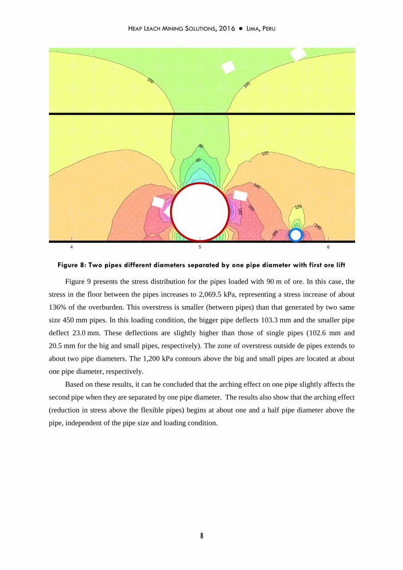
Two pipes with different diameters separated by one pipe diameter.
Two pipes with different diameters are placed in the floor separated one diameter (bigger pipe) apart.
One pipe has a diameter of 450 mm and the second pipe has a diameter of 100 mm, which is the typical
size for laterals in a solution collection system. As expected, the stress distribution of two pipes with
different diameters is not symmetrical. The stresses between the pipes are interconnected. For the case
when the pipes are loaded with the first lift, the stress in a portion of the floor near the smaller pipe
increases to about 167 kPa (Figure 8), representing a stress increase of approximately 134% of the
overburden. In this case, the bigger pipe deflects 7.4 mm and the smaller pipe deflect 1.6 mm. These
deflections are similar to those of single pipes (7.4 mm and 1.5 mm for the big and small pipes,
respectively). The 80 kPa contours above the big and small pipes are located at about one pipe diameter,
respectively.
1,400
1,200 1,600
1,800
2,400
Distance - m
0 1 2 3 4 5 6 7 8 9 10
HEAP LEACH MINING SOLUTIONS, 2016 ● LIMA, PERU
8
Figure 8: Two pipes different diameters separated by one pipe diameter with first ore lift
Figure 9 presents the stress distribution for the pipes loaded with 90 m of ore. In this case, the
stress in the floor between the pipes increases to 2,069.5 kPa, representing a stress increase of about
136% of the overburden. This overstress is smaller (between pipes) than that generated by two same
size 450 mm pipes. In this loading condition, the bigger pipe deflects 103.3 mm and the smaller pipe
deflect 23.0 mm. These deflections are slightly higher than those of single pipes (102.6 mm and
20.5 mm for the big and small pipes, respectively). The zone of overstress outside de pipes extends to
about two pipe diameters. The 1,200 kPa contours above the big and small pipes are located at about
one pipe diameter, respectively.
Based on these results, it can be concluded that the arching effect on one pipe slightly affects the
second pipe when they are separated by one pipe diameter. The results also show that the arching effect
(reduction in stress above the flexible pipes) begins at about one and a half pipe diameter above the
pipe, independent of the pipe size and loading condition.
120
120
140
100
120
80
60
100
10
0
80
60
120
140
18
0
160
16
0
Distance - m
0 1 2 3 4 5 6 7 8 9 10

HEAP LEACH MINING SOLUTIONS, 2016 ● LIMA, PERU
9
Figure 9: Two pipes different diameters separated by one pipe diameter with 90 m of ore
The pipe deflections and the stress increases are used to evaluate de arching effect on adjacent
pipes. Table 2 presents a summary of these parameters obtained from the numerical modeling.
Table 2: Summary of results
Case
Deflection first lift/25 lifts
(%)
Stress Increase on the floor first lift/15 lifts
(%)
Single pipe 450 mm diameter 1.6/22.4 132/134
Single pipe 100 mm diameter 1.5/20.5 140/141
Two 450 mm pipes separated five pipe diameter
1.6/22.5 134/135
Two 459 mm pipes separated one pipe diameter
1.7/24.3 162/164 (between pipes)
One 450 mm pipe and one 100 pipe separated one pipe (450 mm) diameter
1.6/22.6 (450 mm pipe) 1.6/23.0 (100 mm pipe)
154/155 (between pipes)
Conclusion
The results indicate that the arching action of one pipe does not substantially increase the stress on top
of the adjacent pipe. The arching effect (reduction in stress above the flexible pipes) begins between
one to one and a half pipe diameter above the pipe and is independent of both the pipe size and the
loading condition.
The calculated deflection of a single pipe is somewhat similar to the deflection of two adjacent
pipes. Adjacent pipes develop their own arching effect causing a redistributing of stresses on the
adjacent zones, in between the pipes and outside the pipes. The overstress generated in the zone between
the pipes is larger than that outside the pipes.
1,200
1,400
1,600
1,800
1,400 2,000
Distance - m
0 1 2 3 4 5 6 7 8 9 10

HEAP LEACH MINING SOLUTIONS, 2016 ● LIMA, PERU
10
Pipes of the same size separated by one pipe diameter generate higher stresses in the floor between
the pipes compared to the zone outside the pipes. This is caused by the combined arching effect of both
pipes over the zone between the pipes. A big pipe and a small pipe separated by one pipe diameter
generate also higher stresses in the floor between the pipes, but the resulting stresses are not as high as
those generated by same size pipes.
It is a myth that two adjacent pipes should be separated more than five pipe diameters. Based on
the results of this modeling effort, it is concluded that parallel pipes can be placed even at one pipe
diameter apart. Shorter separation between pipes is not recommended because it is impractical to place
and compact overliner between the pipes.
Provisions should be made to protect the geomembrane in zones of high stress. The overstress
zone generated by adjacent pipes for high heaps extends to about two pipe diameters.
An important parameter in pipe deflection modeling is the modulus of soil reaction which is not a
soil property. It is an empirical soil parameter that has to be back-calculated with experiments measuring
the deflection of pipes subject to different loadings. Another option is to determine the constrained soil
modulus performing one-dimensional tests and then calculating the modulus of soil reaction using a
constant k, whose value lies between 0.7 and 1.5.
References
Burns, J.O., and Richard, R.M. 1964. Attenuation of Stresses for Stresses for Buried Cylinders. Proceedings, Symposium
on Soil-Structure Interaction, pp. 378-392. University of Arizona, Tucson, Arizona.
Chambers, R.F., McGrath, T.J. and Heger, F.J. 1980. Plastic Pipe for Subsurface Drainage of Transportation Facilities.
NCHRP. Report 225, Transportation Research Board, pp. 122-140. Washington, D.C.
Leduc, M. and Smith, M. 2004. Solution collection pipes and overstressing of geomembrane liners, The Mining Record.
Smith, M. 2004. Drainage pipe deflection for high heaps, The Mining Record, 4th qt. 2004.
Smith, M., Beck, A., Thiel, R., and Metzler, P. 2005. Designing for vertical pipe deflection under high loads, Proceedings of
the NAGS/GRI-19 Conference, Las Vegas, Nevada, USA.