technical guide - libelium · solar powered ... • read through the document “general conditions...
TRANSCRIPT
Smart Agriculture 30Technical Guide
-2- v76
Index
Document version v76 - 112017 copy Libelium Comunicaciones Distribuidas SL
INDEX
1 General 511 General and safety information 512 Conditions of use 5
2 New version Smart Agriculture v30 7
3 Waspmote Plug amp Sense 831 Features 832 General view 933 Specifications 934 Parts included 1235 Identification1336 Sensor probes 1537 Solar powered 1638 External Battery Module 1839 Programming the Nodes 19310 Program in minutes 20311 Radio interfaces 21312 Industrial Protocols 22313 GPS 24314 Models 25
3141 Smart Agriculture 26
4 Hardware 2941 General description 2942 Specifications 2943 Electrical characteristics 2944 Agriculture v30 Board versions 30
5 Sensors 3151 Temperature humidity and pressure sensor (BME280) 31
511 Specifications 31512 Measurement process 32513 Socket 33
52 Leaf Wetness sensor (LWS) 34521 Specifications 34522 Measurement process 34523 Socket 34
53 Soil moisture sensor (Watermark) 35531 Specifications 35
-3- v76
Index
532 Measurement process 35533 Socket 36
54 Soil temperature sensor (DS18B20) 38541 Specifications 38542 Measurement Process38543 Socket 38
55 Soil temperature sensor (Pt-1000) 39551 Specifications 39552 Measurement process 39553 Socket 40
56 Trunk diameter dendrometer (Ecomatik DC3) 41561 Specifications 41562 Installation process 42563 Measurement process 42564 Socket 43
57 Stem diameter dendrometer (Ecomatik DD-S) 44571 Specifications 44572 Installation process 44573 Measurement process 45574 Socket 46
58 Fruit diameter dendrometer (Ecomatik DF) 47581 Specifications 47582 Installation process 48583 Measurement process 49584 Socket 51
59 Solar radiation sensor - PAR (SQ-110) 52591 Specifications 52592 Measurement process 53593 Socket 54
510 Ultraviolet Radiation sensor (SU-100) 555101 Specifications 555102 Measurement process 565103 Socket 56
511 Weather station (WS-3000) 575111 Anemometer 575112 Wind vane 595113 Pluviometer61
512 Ultrasonic Sensor (MaxSonarreg from MaxBotixtrade) 635121 Specifications 635122 Measurement Process 655123 Socket 66
513 Luminosity sensor (TSL2561) 675131 Specifications 675132 Measurement process 67
-4- v76
514 Sockets for casing 68
6 Board configuration and programming 7161 Hardware configuration 7162 API 71
621 Agriculture Class 71622 dendrometerClass 72623 ds18b20Class 72624 leafWetnessClass 72625 pt1000Class 72626 radiationClass 72627 watermarkClass 73628 weatherStationClass73
7 API changelog 74
8 Documentation changelog 75
9 Consumption 7691 Tables of consumption 7692 Low consumption mode 76
10 Maintenance 77
11 Disposal and recycling 78
12 Certifications 79
Appendix 1 Watermark sensorrsquos interpretation reference 80
Appendix 2 Solar sensors mounting accessory installation guide 83
Index
-5- v76
General
1 GeneralImportant
All documents and any examples they contain are provided as-is and are subject to change without notice Except to the extent prohibited by law Libelium makes no express or implied representation or warranty of any kind with regard to the documents and specifically disclaims the implied warranties and conditions of merchantability and fitness for a particular purpose
The information on Libeliumrsquos websites has been included in good faith for general informational purposes only It should not be relied upon for any specific purpose and no representation or warranty is given as to its accuracy or completeness
11 General and safety information bull In this section the term ldquoWaspmoterdquo encompasses both the Waspmote device itself and its modules and
sensor boards bull Read through the document ldquoGeneral Conditions of Libelium Sale and Userdquo bull Do not allow contact of metallic objects with the electronic part to avoid injuries and burns bull NEVER submerge the device in any liquid bull Keep the device in a dry place and away from any liquid which may spill bull Waspmote consists of highly sensitive electronics which is accessible to the exterior handle with great care
and avoid bangs or hard brushing against surfaces bull Check the product specifications section for the maximum allowed power voltage and amperage range and
consequently always use a current transformer and a battery which works within that range Libelium is only responsible for the correct operation of the device with the batteries power supplies and chargers which it supplies
bull Keep the device within the specified range of temperatures in the specifications section bull Do not connect or power the device with damaged cables or batteries bull Place the device in a place only accessible to maintenance personnel (a restricted area) bull Keep children away from the device in all circumstances bull If there is an electrical failure disconnect the main switch immediately and disconnect that battery or any
other power supply that is being used bull If using a car lighter as a power supply be sure to respect the voltage and current data specified in the ldquoPower
Suppliesrdquo section bull If using a battery in combination or not with a solar panel as a power supply be sure to use the voltage and
current data specified in the ldquoPower suppliesrdquo section bull If a software or hardware failure occurs consult the Libelium Web Development section bull Check that the frequency and power of the communication radio modules together with the integrated
antennas are allowed in the area where you want to use the device bull Waspmote is a device to be integrated in a casing so that it is protected from environmental conditions such
as light dust humidity or sudden changes in temperature The board supplied ldquoas isrdquo is not recommended for a final installation as the electronic components are open to the air and may be damaged
12 Conditions of use bull Read the ldquoGeneral and Safety Informationrdquo section carefully and keep the manual for future consultation bull Use Waspmote in accordance with the electrical specifications and the environment described in the ldquoElectrical
Datardquo section of this manual bull Waspmote and its components and modules are supplied as electronic boards to be integrated within a final
product This product must contain an enclosure to protect it from dust humidity and other environmental interactions In the event of outside use this enclosure must be rated at least IP-65
bull Do not place Waspmote in contact with metallic surfaces they could cause short-circuits which will permanently damage it
-6- v76
General
Further information you may need can be found at httpwwwlibeliumcomdevelopmentwaspmote
The ldquoGeneral Conditions of Libelium Sale and Userdquo document can be found athttpwwwlibeliumcomdevelopmentwaspmotetechnical_service
-7- v76
New version Smart Agriculture v30
2 New version Smart Agriculture v30This guide explains the new Smart Agriculture Sensor Board v30 This board was specifically designed for our new product lines Waspmote v15 and Plug amp Sense v15 released on October 2016
This board is not compatible with Waspmote v12 or Plug amp Sense v12 so it is NOT recommended to mix product generations If you are using previous versions of our products please use the corresponding guides available on our Development website
You can get more information about the generation change on the document ldquoNew generation of Libelium product linesrdquo
Differences of Smart Agriculture v30 with previous versions
bull Included the new BME280 temperature humidity and air pressure sensor This tiny digital and cost-efficient sensor measures 3 parameters with great accuracy and range
bull The BME280 replaces the previous analog Temperature sensor (MCP9700A) the analog Humidity sensor (808H5V5) the double Sensirion sensor (SHT75) and the Atmospheric Pressure sensor (MPX4115A)
bull Many internal changes have been made on the board circuitry to reduce the BoM Now some sensors are multiplexed avoiding duplicate parts
bull Clearer silkscreen for easier connection bull Digital Bus socket allows the connections of digital sensors bull Added an Digital Bus isolator chip to avoid affecting to the Waspmote Digital Bus bull The library has been improved to make easier the board handling bull New connectors to improve the Plug amp Sense wiring making it more robust bull Included ultrasound sensor and luminosity sensor
-8- v76
Waspmote Plug amp Sense
3 Waspmote Plug amp SenseThe Waspmote Plug amp Sense line allows you to easily deploy Internet of Things networks in an easy and scalable way ensuring minimum maintenance costs The platform consists of a robust waterproof enclosure with specific external sockets to connect the sensors the solar panel the antenna and even the USB cable in order to reprogram the node It has been specially designed to be scalable easy to deploy and maintain
Note For a complete reference guide download the ldquoWaspmote Plug amp Sense Technical Guiderdquo in the Development section of the Libelium website
31 Features bull Robust waterproof IP65 enclosure bull Add or change a sensor probe in seconds bull Solar powered with internal and external panel options bull Radios available 802154 868 MHz 900 MHz WiFi 4G Sigfox and LoRaWAN bull Over the air programming (OTAP) of multiple nodes at once (via WiFi or 4G radios) bull Special holders and brackets ready for installation in street lights and building fronts bull Graphical and intuitive interface Programming Cloud Service bull Built-in 3-axes accelerometer bull External contactless reset with magnet bull Optional industrial protocols RS-232 RS-485 Modbus CAN Bus bull Optional GPS receiver bull Optional External Battery Module bull External SIM connector for the 4G models bull Fully certified CE (Europe) FCC (USA) IC (Canada) ANATEL (Brazil) RCM (Australia) PTCRB (USA cellular
connectivity) ATampT (USA cellular connectivity)
Figure Waspmote Plug amp Sense
-9- v76
Waspmote Plug amp Sense
32 General viewThis section shows main parts of Waspmote Plug amp Sense and a brief description of each one In later sections all parts will be described deeply
33 Specifications bull Material polycarbonate bull Sealing polyurethane bull Cover screws stainless steel bull Ingress protection IP65 bull Impact resistance IK08 bull Rated insulation voltage AC 690 V bull Rated insulation voltage DC 1000 V bull Heavy metals-free Yes bull Weatherproof true - nach UL 746 C bull Ambient temperature (min) -30 degC bull Ambient temperature (max) 70 degC bull Approximated weight 800 g
Temporary extreme temperatures are supported Regular recommended usage -20 +60 ordmC
In the pictures included below it is shown a general view of Waspmote Plug amp Sense main parts Some elements are dedicated to node control others are designated to sensor connection and other parts are just identification elements All of them will be described along this guide
164 mm
124 mm
175
mm
410
mm
160
mm
122
mm
85 mm
Figure Main view of Waspmote Plug amp Sense
-10- v76
Waspmote Plug amp Sense
Figure Control side of the enclosure
Figure Control side of the enclosure for 4G model
Figure Sensor side of the enclosure
-11- v76
Waspmote Plug amp Sense
Figure Antenna side of the enclosure
Figure Front view of the enclosure
Figure Back view of the enclosure
-12- v76
Waspmote Plug amp Sense
Figure Warranty stickers of the enclosure
Important note Do not handle black stickers seals of the enclosure (Warranty stickers) Their integrity is the proof that Waspmote Plug amp Sense has not been opened If they have been handled damaged or broken the warranty is automatically void
34 Parts includedNext picture shows Waspmote Plug amp Sense and all of its elements Some of them are optional accessories that may not be included
1
2
34
5
7
68
9
10
Figure Waspmote Plug amp Sense accessories 1 enclosure 2 sensor probes 3 external solar panel 4 USB cable 5 antenna 6 cable ties 7 mounting feet (screwed to the enclosure) 8 extension cord 9 solar panel cable 10 wall plugs amp screws
-13- v76
Waspmote Plug amp Sense
35 IdentificationEach Waspmote model is identified by stickers Next figure shows front sticker
Model identification colour
Enclosure model
Figure Front sticker of the enclosure
There are many configurations of Waspmote Plug amp Sense line all of them identified by one unique sticker Next image shows all possibilities
Figure Different front stickers
-14- v76
Waspmote Plug amp Sense
Moreover Waspmote Plug amp Sense includes a back sticker where it is shown identification numbers radio MAC addresses etc It is highly recommended to annotate this information and save it for future maintenance Next figure shows it in detail
Figure Back sticker
Sensor probes are identified too by a sticker showing the measured parameter and the sensor manufacturer reference
CO - TGS2442Measure
parameterSensor reference
Figure Sensor probe identification sticker
-15- v76
Waspmote Plug amp Sense
36 Sensor probesSensor probes can be easily attached by just screwing them into the bottom sockets This allows you to add new sensing capabilities to existing networks just in minutes In the same way sensor probes may be easily replaced in order to ensure the lowest maintenance cost of the sensor network
Figure Connecting a sensor probe to Waspmote Plug amp Sense
Go to the Plug amp Sense Sensor Guide to know more about our sensor probes
-16- v76
Waspmote Plug amp Sense
37 Solar poweredThe battery can be recharged using the waterproof USB cable but also the internal or external solar panel options
The external solar panel is mounted on a 45ordm holder which ensures the maximum performance of each outdoor installation
Figure Waspmote Plug amp Sense powered by an external solar panel
For the internal option the solar panel is embedded on the front of the enclosure perfect for use where space is a major challenge
Figure Internal solar panel
-17- v76
Waspmote Plug amp Sense
Figure Waspmote Plug amp Sense powered by an internal solar panel
-18- v76
Waspmote Plug amp Sense
38 External Battery ModuleThe External Battery Module (EBM) is an accessory to extend the battery life of Plug amp Sense The extension period may be from months to years depending on the sleep cycle and radio activity The daily charging period is selectable among 5 15 and 30 minutes with a selector switch and it can be combined with a solar panel to extend even more the nodersquos battery lifetime
Note Nodes using solar panel can keep using it through the External Battery Module (EBM) The EBM is connected to the solar panel connector of Plug amp Sense and the solar panel unit is connected to the solar panel connector of the EBM
Figure Plug amp Sense with External Battery Module
Figure Plug amp Sense with External Battery Module and solar panel
-19- v76
Waspmote Plug amp Sense
39 Programming the NodesWaspmote Plug amp Sense can be reprogrammed in two ways
The basic programming is done from the USB port Just connect the USB to the specific external socket and then to the computer to upload the new firmware
Figure Programming a node
Over the Air Programming (OTAP) is also possible once the node has been installed (via WiFi or 4G radios) With this technique you can reprogram wireless one or more Waspmote sensor nodes at the same time by using a laptop and Meshlium
Figure Typical OTAP process
-20- v76
Waspmote Plug amp Sense
310 Program in minutesThe Programming Cloud Service is an intuitive graphic interface which creates code automatically The user just needs to to fill a web form to obtain binaries for Plug amp Sense Advanced programming options are available depending on the license selected
Check how easy it is to handle the Programming Cloud Service at
httpscloudlibeliumcom
Figure Programming Cloud Service
-21- v76
Waspmote Plug amp Sense
311 Radio interfaces
Radio Protocol Frequency bands
Transmission power Sensitivity Range Certification
XBee-PRO 802154 EU 802154 24 GHz 10 dBm -100 dBm 750 m CE
XBee-PRO 802154 802154 24 GHz 18 dBm -100 dBm 1600 m FCC IC ANATEL RCM
XBee 868LP RF 868 MHz 14 dBm -106 dBm 84 km CE
XBee 900HP US RF 900 MHz 24 dBm -110 dBm 155 km FCC IC
XBee 900HP BR RF 900 MHz 24 dBm -110 dBm 155 km ANATEL
XBee 900HP AU RF 900 MHz 24 dBm -110 dBm 155 km RCM
WiFi
WiFi(HTTP(S) FTP TCP
UDP)
24 GHz 17 dBm -94 dBm 500 m CE FCC IC ANATEL RCM
4G EUBR
4G3G2G
(HTTP FTP TCP UDP)
GPS
800 850 900 1800 2100 2600
MHz
4G class 3 (02 W 23 dBm)
4G -102 dBm
- km - Typical base station
rangeCE ANATEL
4G US
4G3G2G(HTTP FTP TCP UDP)
GPS
700 850 1700 1900 MHz
4G class 3 (02 W 23 dBm)
4G -103 dBm
- km - Typical base station
range
FCC IC PTCRB ATampT
4G AU4G
(HTTP FTP TCP UDP)
700 1800 2600 MHz
4G class 3 (02 W 23 dBm)
4G -102 dBm
- km - Typical base station
rangeRCM
Sigfox EU Sigfox 868 MHz 16 dBm -126 dBm- km - Typical base station
rangeCE
Sigfox US Sigfox 900 MHz 24 dBm -127 dBm- km - Typical base station
rangeFCC IC
LoRaWAN EU LoRaWAN 868 MHz 14 dBm -136 dBm gt 15 km CE
LoRaWAN US LoRaWAN 900 MHz 185 dBm -136 dBm gt 15 km FCC IC
Line of sight and Fresnel zone clearance with 5dBi dipole antenna
-22- v76
Waspmote Plug amp Sense
312 Industrial ProtocolsBesides the main radio of Waspmote Plug amp Sense it is possible to have an Industrial Protocol module as a secondary communication option This is offered as an accessory feature
The available Industrial Protocols are RS-232 RS-485 Modbus (software layer over RS-232 or RS-485) and CAN Bus This optional feature is accessible through an additional dedicated socket on the antenna side of the enclosure
Figure Industrial Protocols available on Plug amp Sense
-23- v76
Waspmote Plug amp Sense
Finally the user can choose between 2 probes to connect the desired Industrial Protocol A standard DB9 connector and a waterproof terminal block junction box These options make the connections on industrial environments or outdoor applications easier
Figure DB9 probe
Figure Terminal box probe
-24- v76
Waspmote Plug amp Sense
313 GPSAny Plug amp Sense node can incorporate a GPS receiver in order to implement real-time asset tracking applications The user can also take advantage of this accessory to geolocate data on a map An external waterproof antenna is provided its long cable enables better installation for maximum satellite visibility
Figure Plug amp Sense node with GPS receiver
Chipset JN3 (Telit)Sensitivity
bull Acquisition -147 dBm bull Navigation -160 dBm bull Tracking -163 dBm
Hot start time lt1 sCold start time lt35 s
Positional accuracy error lt 25 mSpeed accuracy lt 001 msEGNOS WAAS GAGAN and MSAS capability
Antenna
bull Cable length 2 m bull Connector SMA bull Gain 26 dBi (active)
Available information latitude longitude altitude speed direction dateamptime and ephemeris management
-25- v76
Waspmote Plug amp Sense
314 ModelsThere are some defined configurations of Waspmote Plug amp Sense depending on which sensors are going to be used Waspmote Plug amp Sense configurations allow to connect up to six sensor probes at the same time
Each model takes a different conditioning circuit to enable the sensor integration For this reason each model allows to connect just its specific sensors
This section describes each model configuration in detail showing the sensors which can be used in each case and how to connect them to Waspmote In many cases the sensor sockets accept the connection of more than one sensor probe See the compatibility table for each model configuration to choose the best probe combination for the application
It is very important to remark that each socket is designed only for one specific sensor so they are not interchangeable Always be sure you connected probes in the right socket otherwise they can be damaged
Figure Identification of sensor sockets
-26- v76
Waspmote Plug amp Sense
3141 Smart AgricultureThe Smart Agriculture models allow to monitor multiple environmental parameters involving a wide range of applications It has been provided with sensors for air and soil temperature and humidity solar visible radiation wind speed and direction rainfall atmospheric pressure etc
The main applications for this Waspmote Plug amp Sense model are precision agriculture irrigation systems greenhouses weather stations etc Refer to Libelium website for more information
Two variants are possible for this model normal and PRO Next section describes each configuration in detail
Figure Smart Agriculture Waspmote Plug amp Sense model
-27- v76
Waspmote Plug amp Sense
31411 Normal
Sensor sockets are configured as shown in the figure below
Sensor Socket
Sensor probes allowed for each sensor socketParameter Reference
A Weather Station WS-3000 (anemometer + wind vane + pluviometer) 9256-P
B Soil Moisture 1 9248-P 9324-P 9323-PC Soil Moisture 3 9248-P 9324-P 9323-P
D
Soil Temperature 86949-PTemperature + Humidity + Pressure 9370-PLuminosity (Luxes accuracy) 9325-PUltrasound (distance measurement) 9246-P
ELeaf Wetness 9249-PSoil Moisture 2 9248-P 9324-P 9323-P
F (digital bus)
Temperature + Humidity + Pressure 9370-PLuminosity (Luxes accuracy) 9325-PUltrasound (distance measurement) 9246-P
Figure Sensor sockets configuration for Smart Agriculture model
Note For more technical information about each sensor probe go to the Development section on the Libelium website
-28- v76
Waspmote Plug amp Sense
31412 PRO
Sensor sockets are configured as shown in the figure below
Sensor Socket
Sensor probes allowed for each sensor socketParameter Reference
A Weather Station WS-3000 (anemometer + wind vane + pluviometer) 9256-P
BSoil Moisture 1 9248-P 9324-P 9323-PSolar Radiation (PAR) 9251-PUltraviolet Radiation 9257-P
CSoil Moisture 3 9248-P 9324-P 9323-PDendrometers 9252-P 9253-P 9254-P
D (digital bus)
Soil Temperature (Pt-1000) 9255-PTemperature + Humidity + Pressure 9370-PLuminosity (Luxes accuracy) 9325-PUltrasound (distance measurement) 9246-P
ELeaf Wetness 9249-PSoil Moisture 2 9248-P 9324-P 9323-P
F (digital bus)
Temperature + Humidity + Pressure 9370-PLuminosity (Luxes accuracy) 9325-PUltrasound (distance measurement) 9246-P
Figure Sensor sockets configuration for Smart Agriculture PRO model
Ask Libelium Sales Department for more information
Note For more technical information about each sensor probe go to the Development section on the Libelium website
-29- v76
Hardware
4 Hardware41 General descriptionThe Waspmote Agriculture v30 Board allows to monitor multiple environmental parameters involving a wide range of applications from growing development analysis to weather observation For this it has been provided with sensors for air and soil temperature and humidity luminosity solar radiation (PAR and UV) wind speed and direction rainfall atmospheric pressure leaf wetness distance and fruit or trunk diameter (dendrometer) Up to 15 sensors can be connected With the objective of extending the durability of the device after the deployment the board is endowed with a solid state switches system that facilitates a precise regulation of its power prolonging the life of the battery
42 Specifications
Weight 20 gDimensions 735 x 51 x 13 mm Temperature Range [-20 ordmC 65 ordmC]
Figure Upper side
43 Electrical characteristicsBoard power voltages 33 V amp 5 VSensor power voltages 33 V amp 5 VMaximum admitted current (continuous) 200 mAMaximum admitted current (peak) 400 mA
-30- v76
Hardware
44 Agriculture v30 Board versionsThe Agriculture v30 Board for Waspmote includes all the electronics and sockets necessary to connect the most typical sensors in agriculture applications air temperature humidity and atmospheric pressure (BME280) soil moisture (Watermark) soil temperature (DS18B20) leaf wetness (LWS) Weather Station (WS-3000 includes pluviometer anemometer and vane) luxes sensor (TSL2561) and distance (MB7040 or MB7070) The PRO version of the board includes the necessary components for more specific applications such as the solar radiation sensor (SQ-110 or SU-100) the dendrometers (DD-S DC3 and DF) and the soil temperature sensor Pt-1000
Sensors in the Agriculture v30 Board (ldquoStandardrdquo or ldquoNormalrdquo version)
bull Temperature humidity and atmospheric pressure sensor BME280 by Bosch bull Soil moisture sensor Watermark by Irrometer bull Leaf wetness sensor LWS bull Weather Station WS-3000 (Anemometer Wind Vane and Pluviometer) bull Soil temperature sensor DS18B20 bull Distance sensor (MB7040 or MB7070) by MaxBotix bull Luminosity sensor TSL2561
Sensors added in the PRO version (includes advanced electronics for integrating special sensors)
bull Solar radiation sensor SQ-110 by Apogee bull Ultraviolet radiation sensor SU-100 by Apogee bull DC3 DD-S and DF dendrometers by Ecomatik bull Soil temperature sensor Pt-1000
-31- v76
Sensors
5 Sensors51 Temperature humidity and pressure sensor (BME280)
Note Only one BME280 sensor is supported at the same time
511 Specifications
Electrical characteristics bull Supply voltage 33 V bull Sleep current typical 01 μA bull Sleep current maximum 03 μA
Temperature sensor bull Operational range -40 ~ +85 ordmC bull Full accuracy range 0 ~ +65 ordmC bull Accuracy plusmn1 ordmC (range 0 ordmC ~ +65 ordmC) bull Response time 165 seconds (63 response from +30 to +125 degC) bull Typical consumption 1 μA measuring
Humidity sensor bull Measurement range 0 ~ 100 of Relative Humidity (for temperatures lt 0 degC and gt 60 degC see figure below) bull Accuracy lt plusmn3 RH (at 25 ordmC range 20 ~ 80) bull Hysteresis plusmn1 RH bull Operating temperature -40 ~ +85 ordmC bull Response time (63 of step 90 to 0 or 0 to 90) 1 second bull Typical consumption 18 μA measuring bull Maximum consumption 28 μA measuring
Figure Humidity sensor operating range
Figure BME280 sensor
-32- v76
Sensors
Pressure sensor bull Measurement range 30 ~ 110 kPa bull Operational temperature range -40 ~ +85 ordmC bull Full accuracy temperature range 0 ~ +65 ordmC bull Absolute accuracy plusmn01 kPa (0 ~ 65 ordmC) bull Typical consumption 28 μA measuring bull Maximum consumption 42 μA measuring
512 Measurement process
The BME280 is as combined digital humidity pressure and temperature sensor based on
proven sensing principles The humidity sensor provides an extremely fast response time for fast context awareness applications and high overall accuracy over a wide temperature range
The pressure sensor is an absolute barometric pressure sensor with extremely high accuracy and resolution and drastically lower noise
The integrated temperature sensor has been optimized for lowest noise and highest resolution
Its output is used for temperature compensation of the pressure and humidity sensors and can also be used for estimation of the ambient temperature
When the sensor is disabled current consumption drops to 01 μA
To read this sensor you should use the following functions
Temperature bull Reading code
floattemp AgricultureON() ReadsthetemperaturefromBME280sensor temp=AgriculturegetTemperature()
Humidity bull Reading code
floathumd AgricultureON() ReadsthehumidityfromBME280sensor humd=AgriculturegetHumidity()
Pressure bull Reading code
floatpres AgricultureON() ReadsthepressurefromBME280sensor pres=AgriculturegetPressure()
You can find a complete example code for reading the BME280 sensor in the following linkhttpwwwlibeliumcomdevelopmentwaspmoteexamplesag-v30-01-temperature-sensor-reading
-33- v76
Sensors
513 Socket
Figure Image of the socket for the BME280 sensor
In the image above we can see highlighted the four pins of the terminal block where the sensor must be connected to the board The white dot on the BME280 must match the mark on the Agriculture sensor board
-34- v76
Sensors
52 Leaf Wetness sensor (LWS)
521 Specifications
Resistance Range 5 kΩ ~ gt2 MΩOutput Voltage Range 1 V ~ 33 VLength 395 cmWidth 195 cm
522 Measurement process
The leaf wetness sensor behaves as a resistance of a very high value (infinite for practical purposes) in absence of condensation in the conductive combs that make it up and that may fall down when it is completely submerged in water The voltage at its output is inversely proportional to the humidity condensed on the sensor and can be read at the analog input of Waspmote ANALOG3when selected the proper output of a multiplexer that connects this sensor and one of the Watermark soil humidity sensors to that analog pin The value returned by the reading function of the library corresponds to the percentage of condensation present on the sensor The power supply of the sensor (33 V) can be cut off or connected through the switched controlled by the digital pin ANALOG7 It is highly recommended to switch off this sensor in order to minimize the global consumption of the board (you can find more information about the consumption of the board and how to handle it in chapter ldquoBoard configuration and programmingrdquo)
Reading code
Variabletostorethereadvalue floatvalue_lw Instancesensorobject leafWetnessClasslwSensor AgricultureON() Readtheleafwetnesssensor value_lw=lwSensorgetLeafWetness()
You can find a complete example code for reading the leaf wetness sensor in the following link
httpwwwlibeliumcomdevelopmentwaspmoteexamplesag-v30-02-leaf-wetness-sensor-reading
523 Socket
Figure Image of the socket for the Leaf Wetness sensor
In the image above we can see highlighted the two pins of the terminal block where the sensor must be connected to the board
Figure Leaf Wetness sensor
-35- v76
Sensors
53 Soil moisture sensor (Watermark)
531 Specifications
Measurement range 0 ~ 200 cbFrequency Range 50 ~ 10000 Hz approximatelyDiameter 22 mmLength 76 mmTerminals AWG 20
Figure Watermark sensor
Figure Output frequency of the Watermark sensor circuit with respect to the resistance of the sensor
532 Measurement process
The Watermark sensor by Irrometer is a resistive type sensor consisting of two electrodes highly resistant to corrosion embedded in a granular matrix below a gypsum wafer The resistance value of the sensor is proportional to the soil water tension a parameter dependent on moisture that reflects the pressure needed to extract the water from the ground The function of the library readWatermark() returns the frequency output of the sensorrsquos adaptation circuit in Herzs (Hz) for more information about the conversion into soil water tension look at Appendix 1 in this technical guide It is highly recommended to switch off this sensor in order to minimize the global consumption of the board (you can find more information about the consumption of the board and how to handle it in chapter ldquoBoard configuration and programmingrdquo)
-36- v76
Sensors
Reading code
Variabletostorethereadvalue floatwatermark1watermark2watermark3 Instanceobjects watermarkClasswmSensor1(SOCKET_1) watermarkClasswmSensor2(SOCKET_2) watermarkClasswmSensor3(SOCKET_3) AgricultureON()
ReadtheWatermarkssensorsonebyoneUSBprintln(F(ldquoWaitforWatermark1rdquo))watermark1=wmSensor1readWatermark()USBprintln(F(ldquoWaitforWatermark2rdquo))watermark2=wmSensor2readWatermark()USBprintln(F(ldquoWaitforWatermark3rdquo))watermark3=wmSensor3readWatermark() PrintthewatermarkmeasuresUSBprint(F(ldquoWatermark1-Frequencyldquo))USBprint(watermark1)USBprintln(F(ldquoHzrdquo))USBprint(F(ldquoWatermark2-Frequencyldquo))USBprint(watermark2)USBprintln(F(ldquoHzrdquo))USBprint(F(ldquoWatermark3-Frequencyldquo))USBprint(watermark3)USBprintln(F(ldquoHzrdquo))
You can find a complete example code for reading the Watermark sensors in the following linkhttpwwwlibeliumcomdevelopmentwaspmoteexamplesag-v30-07-watermark-sensor-reading
533 Socket
Figure Image of the socket for the Watermark sensor
-37- v76
Sensors
Three sockets for Watermark sensors have been placed in the agriculture board (marked in the image in the figure above) and the electronics necessary for powering and signal conditioning so that the soil moisture can be measured at three different depths
Figure Illustration of the three Watermark sensors placed at different depths
-38- v76
Sensors
54 Soil temperature sensor (DS18B20)
541 Specifications
Measurement range -55 ~ 125 ordmCAccuracy plusmn05 degC accuracy from -10 degC to +85 degCDiameter 7 mmLength 26 mmCable 18 mWaterproof1- Wire interface
Figure DS18B20 sensor
542 Measurement Process
The DS18B20 digital thermometer provides 9-bit Celsius temperature measurements The DS18B20 communicates over a 1-Wire bus that by definition requires only one data line (and ground) for communication with Waspmote
This sensor only is included in the Smart Agriculture Normal version
Reading code
Variabletostorethereadvalue floattemp Instanceobject ds18b20Classds18b20 AgricultureON() Readthetemperaturesensortemp=ds18b20readDS18b20()
You can find a complete example code for reading the DS18B20 sensor in the following linkhttpwwwlibeliumcomdevelopmentwaspmoteexamplesag-v30-12-ds18b20-temperature-sensor-reading
543 Socket
Figure Image of the socket for the DS18B20 sensor
The sensor must be connected to its adaptation stage through a 254 mm pitch We can see an image with the 3 pins of this socket corresponding to the sensor in the previous figure The function of the library readDS18b20() returns the temperature value in Celsius degree (ordmC) The power supplies required by the sensor is 33 V
-39- v76
Sensors
55 Soil temperature sensor (Pt-1000)
551 Specifications
Measurement range -50 ~ 300 ordmCAccuracy DIN EN 60751Resistance (0 ordmC) 1000 ΩDiameter 6 mmLength 40 mmCable 2 m
Figure Output voltage of the Pt-1000 sensor with respect to temperature
552 Measurement process
The resistance of the Pt-1000 sensor varies between approximately 920 Ω and 1200 Ω in the range considered useful in agriculture applications (-20 ~ 50 ordmC approximately) which results in too low variations of voltage at significant changes of temperature for the resolution of the Waspmotersquos analog-to-digital converter The function of the library readPT1000() returns the temperature value in Celsius degree (ordmC) The power supplies required by the sensor both 33 V and 5 V are controlled internally by the library
This sensor can only be read by Smart Agriculture PRO version
Reading code Variabletostorethereadvalue floatvalue_PT1000 Instanceobject pt1000Classpt1000Sensor AgricultureON() ReadPT1000sensor value_PT1000=pt1000SensorreadPT1000()
You can find a complete example code for reading the Pt-1000 sensor in the following linkhttpwwwlibeliumcomdevelopmentwaspmoteexamplesag-v30-06-pt1000-sensor-reading
Figure Pt-1000 sensor
-40- v76
Sensors
553 Socket
Figure Image of the socket for the Pt-1000 sensor
The sensor must be connected to its adaptation stage through a 254 mm pitch We can see an image with the two pins of this socket corresponding to the sensor in the previous figure Both pins of the sensor can be connected to any of the two ways since there is no polarity to be respected
-41- v76
Sensors
56 Trunk diameter dendrometer (Ecomatik DC3)
561 Specifications
Trunkbranch diameter From 2 cmAccuracy plusmn2 μmTemperature coefficient lt01μmKLinearity lt2Operation temperature -30 ~ 40 ordmCOperation humidity 0 ~ 100 RHCable length 2 mOutput range 0 ~ 20 kΩRange of the sensor Function of the size of the tree
Tree Diameter (cm) Measuring Range in Circumference (mm)
Measuring Range in Diameter (mm)
10 3125 994
40 2299 731
100 1658 527
Figure Ecomatik DC3 sensor
Figure Ecomatik DC3 sensor
-42- v76
Sensors
562 Installation process
Cut the rubber band into 2 pieces as long as the tree circumference and bond them with the plug locks together Unroll the wire from the reel turn the thread rods of the turnbuckle to the middle position Thread a certain number (dependent on the tree circumference) of the plastic slides provided on the wire This plastic slides will avoid the wire to be swallowed by the tree cortex Then insert the end of the wire through the sensor hole Finally pass the prepared wire around the tree trunk and fix it on the turnbuckle by the adjusting screw
In the pictures below can be seen how the sensor should look after the installation process
Ensure that the wires lies flat around the trunk and move the plastic slides along the wire so that the wire itself does not touch the bark Then turn the turnbuckle slowly so that the sensor rod is pushed in by about 2-3 mm Fix the cable onto the tree trunkbranch so that the sensor is protected from any accidental pulldrag of the entire cable length This can be done using a rope or cable straps In addition there should be no tension between the sensor and cable Ensure that no rain water can run along the cable into the sensor casing
563 Measurement process
The operation of the 3 Ecomatik dendrometers DC3 DD-S and DF is based on the variation of an internal resistance with the pressure that the growing of the trunk stem branch or fruit exerts on the sensor The circuit permits the reading of that resistance in a full bridge configuration through a 16 bits analog-to-digital converter whose reference is provided by a high precision 3V voltage reference in order to acquire the most accurate and stable measurements possible The reading of the converter shared with the PT-1000 temperature sensor will be carried out through the Digital Bus using the functions of the library WaspSensorAgr_v30 explained in the chapter ldquoAPIrdquo about this API library returning the read value in millimeters (mm) The 33 V and 5 V power supplies of the devices may be cut off or connected via the digital switch controlled internally by the library
This sensor can only be read by Smart Agriculture PRO version
Reading code
Variabletostorethereadvalue floatvalue_dendrometer Instanceobject dendrometerClassdendSensorr(SENS_SA_DC3) AgricultureON() Readthedendrometersensor value_dendrometer=dendSensorreadDendrometer()
You can find a complete example code for reading the dendrometer sensor in the following link
httpwwwlibeliumcomdevelopmentwaspmoteexamplesag-v30-05-dendrometer-sensor-reading
Figure Ecomatik DC2 sensor (previous version) Figure Ecomatik DC3 sensor
-43- v76
Sensors
There is another possibility to take measures using the dendrometer First a reference is stored at the beginning of the code with the setReference() function (it should be run inside the setup()) Then the value returned is calculated with the current value of the dendrometer minus the reference stored as if it was an offset So the measurement will be the upgrowth of the fruit using the readGrowth() function
Variabletostorethereadvalue floatvalue_dendrometer
Instanceobject dendrometerClassdendSensor(SENS_SA_DC3)
AgricultureON()
Thisfunctionreadsthedendrometervalue andsetsitaszeromillimetersreference dendSensorsetReference()
Readthedendrometersensorandreturnthe thedifferencebetweenthisvalueandreference value_dendrometer=dendSensorreadGrowth()
You can find a complete example code for reading the dendrometer sensor in the following link
httpwwwlibeliumcomdevelopmentwaspmoteexamplesag-v30-05b-dendrometer-sensor-reading-with-reference
564 Socket
Figure Image of the socket for the dendrometers
Any of the three dendrometers available may be connected to Waspmote through the two 254 mm pitch terminal blocks marked in the image in the figure above The pins corresponding to the sensor in this terminal block (highlighted in the figure) provide the sensor with connection to ground power supply and to the analog-to-digital converter differential input
-44- v76
Sensors
57 Stem diameter dendrometer (Ecomatik DD-S)
571 Specifications
Stembranch diameter 0 ~ 5 cmRange of the sensor 55 mmOutput range 0 ~ 20 kΩAccuracy plusmn2 μmTemperature coefficient lt01μmKOperation temperature -30 ~ 40 ordmCOperation humidity 0 ~ 100 RHCable length 2 m
Figure Ecomatik DF sensor
572 Installation process
Detach the front frame of the dendrometer to allow you fix the stembranch to be measured Fix the hind plate and hind frame on the stembranch using a rubber band so that the hind plate is firmly held on the stembranch Replace the front part of the frame and fix it with screws Turn the screws slowly to push in the rod for about 2 mm Fix the cable onto the tree stembranch so that the sensor is protected from any accidental pulldrag on the entire cable length This can be done using a rope or cable straps Ensure the suspension ropestrap is not so tight as to interfere with normal tree growth and expansion during the entire measurement period Also there should be no tension between the sensor and cable Ensure that no rain water can run along the cable into the sensor casing
Figure Ecomatik DD-S sensor
-45- v76
Sensors
In the pictures below can be seen how the sensor should look after the installation process
For very small plants the dendrometer can be hung or fixed to a wood stick
573 Measurement process
The operation of the three Ecomatik dendrometers DC3 DD-S and DF is based on the variation of an internal resistance with the pressure that the growing of the trunk stem branch or fruit exerts on the sensor The circuit permits the reading of that resistance in a full bridge configuration through a 16 bits analog-to-digital converter whose reference is provided by a high precision 3V voltage reference in order to acquire the most accurate and stable measurements possible The reading of the converter shared with the Pt-1000 temperature sensor will be carried out through the Digital Bus using the functions of the library WaspSensorAgr_v30 explained in the chapter ldquoAPIrdquo about this API library returning the read value in millimeters (mm) The 33 V and 5 V power supplies of the devices may be cut off or connected via the digital switch controlled internally by the library
This sensor can only be read by Smart Agriculture PRO version
Reading code
Variabletostorethereadvalue floatvalue_dendrometer Instanceobject dendrometerClassdendSensor(SENS_SA_DD) AgricultureON() Readthedendrometersensor value_dendrometer=dendSensorreadDendrometer()
You can find a complete example code for reading the dendrometer sensor in the following link
httpwwwlibeliumcomdevelopmentwaspmoteexamplesag-v30-05-dendrometer-sensor-reading
There is another possibility to take measures using the dendrometer First a reference is stored at the beginning of the code with the setReference() function (it should be run inside the setup()) Then the value returned is calculated with the current value of the dendrometer minus the reference stored as if it was an offset So the measurement will be the upgrowth of the fruit using the readGrowth() function
Figure Ecomatik DD-S sensor (stem) Figure Ecomatik DD-S sensor (stem)
-46- v76
Sensors
Variabletostorethereadvalue floatvalue_dendrometer Instanceobject dendrometerClassdendSensor(SENS_SA_DC3) AgricultureON() Thisfunctionreadsthedendrometervalue andsetsitaszeromillimetersreference dendSensorsetReference() Readthedendrometersensorandreturnthe thedifferencebetweenthisvalueandreference value_dendrometer=dendSensorreadGrowth()
You can find a complete example code for reading the dendrometer sensor in the following link
httpwwwlibeliumcomdevelopmentwaspmoteexamplesag-v30-05b-dendrometer-sensor-reading-with-reference
574 Socket
Figure Image of the socket for the dendrometers
Any of the three dendrometers available may be connected to Waspmote through the two 254mm pitch terminal blocks marked in the image in the figure above The pins corresponding to the sensor in this terminal block (highlighted in the figure) provide the sensor with connection to ground power supply and to the analog-to-digital converter differential input
-47- v76
Sensors
58 Fruit diameter dendrometer (Ecomatik DF)
581 Specifications
Fruit diameter 0 ~ 11 cmRange of the sensor 75 mmOutput range 0 ~ 20 kΩAccuracy plusmn2 μmTemperature coefficient lt01 μmKOperation temperature -30 ~ 40 ordmCOperation humidity 0 ~ 100 RHCable length 2 m
Figure Ecomatik DF sensor
Figure Ecomatik DF sensor
-48- v76
Sensors
582 Installation process
Detach the front frame of the dendrometer to allow you fix the fruit to be measured Insert the fruit carefully between the fixing wires until it rests onto the hind plate Curve the fixing wires accordingly so as to fit the shape of the fruit Ensure that the fruit rests on the hind plate Fix the wires on the fruit using a rubber band so that the fruit is firmly held between the fixing wires and the hind plate Replace the front part of the frame and fix it with screws The complete set-up should be suspended freely from a tree branch using a suspension wire Ensure that the fruit hangs freely and that the branch from which it grows is not strained by the dendrometer Turn the screws slowly to push in the rod about 2 mm Fix the cable onto the tree branch so that the sensor is protected from any accidental pulldrag on the entire cable length This can be done using a rope or cable straps Ensure the suspension ropestrap is not so tight as to interfere with normal tree growth and expansion during the entire measurement period Also there should be no tension between the sensor and cable
In the pictures below can be seen how the sensor should look after the installation process
Figure Ecomatik DF sensor with apple Figure Ecomatik DF sensor with apple
-49- v76
Sensors
Ensure that no rain water can run along the cable into the sensor casing
It may not be necessary but in case the fruit is too small to withstand the dendrometerrsquos frame weight you can adapt the instrument the frames and the screwed rods can be shortened by cutting
583 Measurement process
The operation of the three Ecomatik dendrometers DC3 DD-S and DF is based on the variation of an internal resistance with the pressure that the growing of the trunk stem branch or fruit exerts on the sensor The circuit permits the reading of that resistance in a full bridge configuration through a 16 bits analog-to-digital converter whose reference is provided by a high precision 3 V voltage reference in order to acquire the most accurate and stable measurements possible The reading of the converter shared with the Pt-1000 temperature sensor will be carried out through the Digital Bus using the functions of the library WaspSensorAgr_v30 explained in chapter ldquoAPIrdquo about this API library returning the read value in millimeters (mm) The 33 V and 5 V power supplies of the devices may be cut off or connected via the digital switch controlled internally by the library It is highly recommended to switch off this sensor in order to minimize the global consumption of the board (you can find more information about the consumption of the board and how to handle it in chapter ldquoBoard configuration and programmingrdquo)
This sensor can only be read by Smart Agriculture PRO version
Reading code
Variabletostorethereadvalue floatvalue_dendrometer Instanceobject dendrometerClassdendSensor(SENS_SA_DF) AgricultureON() Readthedendrometersensor value_dendrometer=dendSensorreadDendrometer()
You can find a complete example code for reading the dendrometer sensor in the following linkhttpwwwlibeliumcomdevelopmentwaspmoteexamplesag-v30-05-dendrometer-sensor-reading
Figure Ecomatik DC2 sensor (previous version) Figure Ecomatik DC2 sensor (previous version)
-50- v76
Sensors
There is another possibility to take measures using the dendrometer First a reference is stored at the beginning of the code with the setReference() function (it should be run inside the setup()) Then the value returned is calculated with the current value of the dendrometer minus the reference stored as if it was an offset So the measurement will be the upgrowth of the fruit using the readGrowth() function
Variabletostorethereadvalue floatvalue_dendrometer
Instanceobject dendrometerClassdendSensor(SENS_SA_DC3)
AgricultureON()
Thisfunctionreadsthedendrometervalue andsetsitaszeromillimetersreference dendSensorsetReference()
Readthedendrometersensorandreturnthe thedifferencebetweenthisvalueandreference value_dendrometer=dendSensorreadGrowth()
You can find a complete example code for reading the dendrometer sensor in the following link
httpwwwlibeliumcomdevelopmentwaspmoteexamplesag-v30-05b-dendrometer-sensor-reading-with-reference
-51- v76
Sensors
584 Socket
Figure Image of the socket for the dendrometers
Any of the three dendrometers available may be connected to Waspmote through the 254 mm pitch terminal blocks marked in the image in the figure above The pins corresponding to the sensor in this terminal block (highlighted in the figure) provide the sensor with connection to ground power supply and to the analog-to-digital converter differential input
-52- v76
Sensors
59 Solar radiation sensor - PAR (SQ-110)
591 Specifications
Sensitivity 0200 mV μmolm-2s-1
Calibration factor 5 μmolm-2s-1mVNon-linearity lt1 (up to 4000 μmolm-2s-1)Non-stability (long-term drift) lt2 per yearSpectral range 410 ~ 655 nmAccuracy plusmn5Repeatability lt1Diameter 24 cmHeight 28 cmCable length 5m of shielded twisted-pair wireOperation temperature -40 ~ 70 ordmCOperation humidity 0 ~ 100 RH
Figure Graph of the spectral response of the SQ-110 sensor compared to the photosynthetic response of a plant
Figure SQ-110 sensor
-53- v76
Sensors
592 Measurement process
The SQ-110 sensor specifically calibrated for the detection of solar radiation provides at its output a voltage proportional to the intensity of the light in the visible range of the spectrum a key parameter in photosynthesis processes It presents a maximum output of 400mV under maximum radiation conditions and a sensitivity of 500μmolm-2s-1mV In order to improve the accuracy of the reading this is carried out through a 16 bits analog-to-digital converter that communicates with the microcontroller of the mote through the Digital Bus It can be configured or read using the functions implemented in the API library WaspSensorAgr_v30 for the Agriculture v30 Board The 5 V power supply of this stage is controlled through a digital switch that can be activated and deactivated using the digital pin DIGITAL7
This sensor can only be read by Smart Agriculture PRO version
For a professional installation we advise the use the Solar sensors mounting accessory (see Appendix in this Guide) It works for both OEM sensor and Plug amp Sense probe versions
Reading code
Variabletostoretheradiationconversionvalue floatradiationvalue AgricultureON() Readradiationsensor value=radSensorreadRadiation()Conversionfromvoltageintoumolmiddotm-2middots-1radiation=value00002
You can find a complete example code for reading the SQ-110 sensor in the following link
httpwwwlibeliumcomdevelopmentwaspmoteexamplesag-v30-04-photosynthetic-solar-radiation-sensor-reading
-54- v76
Sensors
593 Socket
Figure Image of the socket for the SQ-110 sensor
This sensor is connected to the analog-to-digital converter through the 3 pins of the 254 mm pitch terminal block marked in the image in the figure above
-55- v76
Sensors
510 Ultraviolet Radiation sensor (SU-100)
5101 Specifications
Sensitivity 02mV μmolm-2s-1
Calibration factor 50μmolm-2s-1mVNon-stability (Long-term drift) lt3 per yearNon-linearity lt1 (up to 300μmolm-2s-1)Spectral range 250 ~ 400nmAccuracy plusmn10Repeatability lt1Diameter 24cmHeight 28cmCable length 5m shielded twisted-pair wireOperation temperature -40 to 70 ordmCOperation humidity 0 ~ 100RH
Figure Graph of the spectral response of the SU-100 sensor compared to the photosynthetic response of a plant
Figure SU-100 sensor
-56- v76
Sensors
5102 Measurement process
The SU-100 sensor complementary to the SQ-110 sensor provides at its output a voltage proportional to the intensity of the light in the ultraviolet range of the spectrum It presents a maximum output of 26mV under maximum radiation conditions and a sensitivity of 02mV μmolm-2s-1 This sensor is read by the mote through the same 16 bits analog-to-digital converter used with the SQ-110 sensor It can be configured or read using the functions implemented in the API library WaspSensorAgr_v30 for the Agriculture v30 Board The 5 V power supply of this stage is controlled through a digital switch that can be activated and deactivated internally by the library
This sensor can only be read by Smart Agriculture PRO version
For a professional installation we advise the use the Solar sensors mounting accessory (see Appendix in this Guide) It works for both OEM sensor and Plug amp Sense probe versions
Reading code
Instanceobject radiationClassradSensor Variabletostoretheradiationconversionvalue floatradiationvalue AgricultureON() Readradiationsensor value=radSensorreadRadiation()Conversionfromvoltageintoumolmiddotm-2middots-1radiation=value00002
You can find a complete example code for reading the SU-100 sensor in the following link
httpwwwlibeliumcomdevelopmentwaspmoteexamplesag-v30-03-ultraviolet_solar_radiation_sensor_reading
5103 Socket
Figure Image of the socket for the SU-100 sensor
This sensor is connected to the analog-to-digital converter through the three pins of the 254 mm pitch terminal block marked in the image in the figure above
-57- v76
Sensors
511 Weather station (WS-3000)This weather station consists of three different sensors described in detail below a wind vane an anemometer and a pluviometer It connects to Waspmote through six wires that must be connected to the terminal block shown in the corresponding figures being the anemometer connected to the vane through an RJ11 socket
Figure Image of the Weather station WS-3000
5111 Anemometer
51111 Specifications
Sensitivity 24kmh turnWind Speed Range 0 ~ 240kmhHeight 71 cmArm length 89 cmConnector RJ11
Figure Anemometer
-58- v76
Sensors
51112 Measurement process
The anemometer chosen for Waspmote consists of a reed switch normally open that closes for a short period of time when the arms of the anemometer complete a 180ordm angle so the output is a digital signal whose frequency will be proportional to the wind speed There will be 2 events in each complete turn That signal can be read from the digital pin DIGITAL2 of the Waspmote The function of the library readAnemometer() returns the wind speed value in kilometers per hour (kmh)The power of the sensor and of the electronics around it may be connected or disconnected using a digital switch controlled internally by the library
Reading code
Variabletostoretheanemometervalue floatanemometer Instanceobjects weatherStationClassanemSensor AgricultureON() ReadAnemometersensor anemometer=anemSensorreadAnemometer()
You can find a complete example code for reading the whole Weather Station WS-3000 data sensor in the following linkhttpwwwlibeliumcomdevelopmentwaspmoteexamplesag-v30-08-weather-station-sensor-reading
51113 Socket
Figure Image of the connector for the anemometer
The way to connect the anemometer to the Agriculture 30 Board is through the vane the anemometerrsquos cable must be plugged into the socket that can be found on the base of the vane
-59- v76
Sensors
5112 Wind vane
51121 Specifications
Height 89 cmLength 178 cmMaximum accuracy 225ordmResistance range 688 Ω ~ 120 kΩ
Figure Wind vane
51122 Measurement process
The wind vane consists of a basement that turns freely on a platform endowed with a net of eight resistances connected to eight switches that are normally and are closed (one or two) when a magnet in the basement acts on them which permits us to distinguish up to 16 different positions (the equivalent to a resolution of 225ordm) The equivalent resistance of the wind vane along with a 10 kΩ resistance form a voltage divider powered at 33 V through a digital switch controlled by the ANALOG1 pin whose output can be measured in the analog input ANALOG5 The function of the library readVaneDirection() also stores in variable vane_direction an 8 bits value which corresponds with an identifier of the pointing direction
Below a table with the different values that the equivalent resistance of the wind vane may take is shown along with the direction corresponding to each value
Direction (degrees) Resistance (kΩ) Voltage (V) Identifier
0 33 253 SENS_AGR_VANE_N
225 657 131 SENS_AGR_VANE_NNE
45 82 149 SENS_AGR_VANE_NE
675 0891 027 SENS_AGR_VANE_ENE
90 1 03 SENS_AGR_VANE_E
1125 0688 021 SENS_AGR_VANE_ESE
135 22 059 SENS_AGR_VANE_SE
1575 141 041 SENS_AGR_VANE_SSE
180 39 092 SENS_AGR_VANE_S
2025 314 079 SENS_AGR_VANE_SSW
225 16 203 SENS_AGR_VANE_SW
2475 1412 193 SENS_AGR_VANE_WSW
270 120 305 SENS_AGR_VANE_W
2925 4212 267 SENS_AGR_VANE_WNW
315 649 286 SENS_AGR_VANE_NW
3375 2188 226 SENS_AGR_VANE_NNW
-60- v76
Sensors
Reading code
Variabletostorethevanevalue intvane Instanceobjects weatherStationClassvaneSensor AgricultureON() ReadVanesensor vane=vaneSensorreadVaneDirection()
You can find a complete example code for reading the whole Weather Station WS-3000 data sensor in the following link
httpwwwlibeliumcomdevelopmentwaspmoteexamplesag-v30-08-weather-station-sensor-reading
Besides it is recommended to use the function getVaneFiltered() in order to perform a mean filtered measurement during a specified period of time Thus mechanical fluctuations will be avoided and a more accurate measurement will be done See example here
httpwwwlibeliumcomdevelopmentwaspmoteexamplesag-v30-09-wind-vane-filtered
51123 Socket
Figure Image of the connector for the wind vane
The wind vane is connected to the board through four pins of a terminal block whose correspondence with the sensorrsquos wire is shown in the figure above
-61- v76
Sensors
5113 Pluviometer
51131 Specifications
Height 905 cmLength 23 cmBucket capacity 028 mm of rain
Figure Pluviometer
51132 Measurement process
The pluviometer consists of a small bucket that once completely filled (028 mm of water approximately) closes a switch emptying automatically afterwards The sensor is connected directly to the Waspmote DIGITAL4 digital input through a pull-up resistance and to the interruption pin RXD1 allowing the triggering of an interruption of the microcontroller when the rainfall provokes a bucket emptying event Since the consumption of this sensor in absence of rain is null no elements of power control have been added for it
The library defines several functions to measure from the pluviometer An inner structure is being used in order to store the number of pluviometer interruptions that took place for the last 24 hours (regarding the RTC settings) The function used for storing a new pulse is called storePulse() and it should be called every time a new pluviometer interruption is generated On the other hand it is possible to know three different values given by the following functions
readPluviometerCurrent() calculates the precipitations in mm for the current period For example it is 1042 am so this function returns the mm of rainfall that took place in the last 42 minutes
readPluviometerHour() calculates the precipitations in the previous one-hour period For example it is 1042 am so this function returns the mm of rainfall between 9 am and 10 am
readPluviometerDay() calculates the accumulated precipitation in the last 24 hours
Tip the user can apply a little of paraffin on the pluviometerrsquos upper surface in order to help the rain drops to flow down to the inside of the sensor
You can find a complete example code for reading the whole Weather Station WS-3000 data sensor in the following linkwwwlibeliumcomdevelopmentwaspmoteexamplesag-v30-08-weather-station-sensor-reading
There is an example of how to use the pluviometer sensor separately from the Weather Stationwwwlibeliumcomdevelopmentwaspmoteexamplesag-v30-10-pluviometer-interruption-reading
-62- v76
Sensors
51133 Socket
Figure Image of the socket for the pluviometer
In the image in the figure above we can see marked the two pins in the terminal block that correspond to the pluviometer (no polarity is required)
-63- v76
Sensors
512 Ultrasonic Sensor (MaxSonarreg from MaxBotixtrade)
5121 Specifications
I2CXL-MaxSonarreg-MB7040tradeOperation frequency 42 kHzMaximum detection distance 765 cmInterface Digital BusPower supply 33 ~ 5 VConsumption (average) 21 mA (powered at 33 V) ndash 32 mA (powered at 5 V)Consumption (peak) 50 mA (powered at 33 V) ndash 100 mA (powered at 5 V)Usage Indoors and outdoors (IP-67)
A 172rdquo dia 438 mm dia
B 200rdquo 507 mm
C 058rdquo 144 mm
D 031rdquo 79 mm
E 018rdquo 46 mm
F 01rdquo 254 mm
G 34rdquo National Pipe Thread Straight
H 1032rdquo dia 262 dia
I 137rdquo 348 mm
weight 176 oz 50 gramsFigure Ultrasonic I2CXL-MaxSonarreg-MB7040 sensor dimensions
Note Only one MB7040 sensor is supported at the same time
In the figure below we can see a diagram of the detection range of the sensor developed using different detection patterns (a 063 cm diameter dowel for diagram A a 254 cm diameter dowel for diagram B an 825 cm diameter rod for diagram C and a 28 cm wide board for diagram D)
Figure Diagram of the sensor beam extracted from the data sheet of the XL-MaxSonarreg-WRA1trade sensor from MaxBotix
Figure Ultrasonic I2CXL-MaxSonarreg-MB7040 from Max-Botixtrade sensor
-64- v76
Sensors
I2CXL-MaxSonarreg-MB1202tradeOperation frequency 42 kHzMaximum detection distance 645 cmSensitivity (analog output) 25 mVcm (powered at 33 V) ndash 38 mVcm (powered at 5 V)Power supply 33 ~ 5 VConsumption (average) 2 mA (powered at 33 V) ndash 3mA (powered at 5 V)Usage Indoors
In the figure below we can see a diagram of the detection range of the sensor developed using different detection patterns (a 063 cm diameter dowel for diagram A a 254 cm diameter dowel for diagram B a 825 cm diameter rod for diagram C and a 28 cm wide board for diagram D)
A 0785rdquo 199 mm H 0100rdquo 254 mm
B 0870rdquo 221 mm J 0645rdquo 164 mm
C 0100rdquo 254 mm K 0610rdquo 155 mm
D 0100rdquo 254 mm L 0735rdquo 187 mm
E 0670rdquo 170 mm M 0065rdquo 17 mm
F 0510rdquo 126 mm N 0038rdquo dia 10 mm dia
G 0124rdquo dia 31 mm dia
weight 43 grams
Figure Diagram of the sensor beam extracted from the data sheet of the Ultrasonic I2CXL-MaxSonarreg-MB1202 sensor from MaxBotix
Figure Ultrasonic I2CXL-MaxSonarreg- MB1202 from MaxBotixtrade sensor
-65- v76
Sensors
5122 Measurement Process
The MaxSonarreg sensors from MaxBotix connects through digital bus interface
In the next figure we can see a drawing of two example applications for the ultrasonic sensors such as liquid level monitoring or presence detection
Figure Examples of application for the MaxSonarreg sensors
The XL-MaxSonarreg-WRA1TM sensor is endowed with an IP-67 casing so it can be used in outdoors applications such as liquid level monitoring in storage tanks
Below a sample code to measure one of the ultrasound sensors (the XL-MaxSonarreg-WRA1) is shown
Reading Code
uint16_tdistance AgricultureON() distance=AgriculturegetDistance()
You can find a complete example code for reading the distance in the following link
wwwlibeliumcomdevelopmentwaspmoteexamplesag-v30-13-ultrasound
-66- v76
Sensors
5123 Socket
These sensors share the socket with the BME280 temperature humidity and pressure sensor The pin correspondence highlighted in the figure below is the same for both
Figure Image of the socket for connecting the MaxSonarreg Sensors
-67- v76
Sensors
513 Luminosity sensor (TSL2561)
5131 Specifications
Electrical characteristicsDynamic range 01 to 40000 luxSpectral range 300 ~ 1100 nmVoltage range 27 ~ 36 VSupply current typical 024 mASleep current maximum 03 μAOperating temperature -30 ~ +70 ordmC
Note Only one TSL2561 sensor is supported at the same time
5132 Measurement process
This is a light-to-digital converter that transforms light intensity into a digital signal output This device combines one broadband photo-diode (visible plus infrared) and one infrared-responding photo-diode on a single CMOS integrated circuit capable of providing a near-photopic response over an effective 20-bit dynamic range (16-bit resolution) Two integrating ADCs convert the photo-diode currents to a digital output that represents the irradiance measured on each channel This digital output in lux is derived using an empirical formula to approximate the human eye response
Reading Code
uint32_tluxes=0 AgricultureON() Readstheluxessensor Selecttheoptionofmeasure -OUTDOOR -INDOOR luxes=AgriculturegetLuxes(INDOOR)
You can find a complete example code for reading the luminosity in the following linkwwwlibeliumcomdevelopmentwaspmoteexamplesag-v30-14-luxes
Figure Image of the socket for the luxes sensor
In the image above we can see highlighted the four pins of the terminal block where the sensor must be connected to the board The white dot luxes board must match the mark of the Agriculture sensor board
Figure Image of the Luminosity sensor
-68- v76
Sensors
514 Sockets for casingIn case the Agriculture v30 board is going to be used in an application that requires the use of a casing such as an outdoors application a series of sockets to facilitate the connection of the sensors through a probe has been disposed
These sockets (PTSM from Phoenix Contact) allow to assemble the wires of the probe simply by pressing them into it To remove the wire press the slot above the input pin and pull off the wire softly
Figure Diagram of a socket extracted from the Phoenix Contact data sheet
In the figure below an image of the board with the sockets in it and the correspondence between its inputs and the sensorrsquos pins is shown
Figure Image of the sockets for casing applications
-69- v76
Sensors
Figure Image of the pin correspondence between the sockets and the sensors
Figure ordmImage of the pin correspondence between the sockets and the sensors
-70- v76
Sensors
Sensor Pin Function
Watermark
1 Watermark 1 +
2 Watermark 1 -
3 Watermark 2 +
4 Watermark 2 -
5 Watermark 3 +
6 Watermark 3 -
Dendrometer
7 Dendrometer -
8 Dendrometer +
9 GND
10 REF3V
Pt-1000DS18B20
11 GND
12 Pt-1000 DS18B20
13 +3V3
Leaf Wetness14 Leaf Wetness +
15 Leaf Wetness -
Solar Radiation
16 Radiation +
17 Radiation -
18 GND
Weather Station WS-3000 (Vane)19 Vane Output (Yellow)
20 GND (Black)
Weather Station WS-3000 ( Anemometer )21 Anemometer Output (Green)
22 GND (Red)
Weather Station WS-3000 (Pluviometer)23 Pluviometer
24 Pluviometer
Digital Bus
25 Digital Bus (SCL)
26 GND
27 Digital Bus (SDA)
28 VCC
-71- v76
Board configuration and programming
6 Board configuration and programming61 Hardware configurationThe Waspmote Agriculture v30 Board hardly requires a manual hardware configuration since all the power control and sensor reading operations can be carried out digitally It will be only necessary to ensure that the sensors are connected in the right way to their sockets for a proper measurement
62 APIThe Agriculture Sensor Board v30 for Waspmote has its own library which contains the set of necessary instructions to easily configure and read each one of the sensors which can be connected to the board Next each one of the functions is described and the process of configuration is detailed for each sensor The specific configuration which must be applied to each one of the sensors is explained in the specific sensorrsquos section
When using the Agriculture Sensor Board v3 on Waspmote remember it is mandatory to include the WaspSensorAgr_v30 library by introducing the next line at the beginning of the code
includeltWaspSensorAgr_v30hgt
Each agriculture sensor needs its own object So between the include of the library and the global variables declaration the object must be created following the next structure
bull Name of the class leafWetnessClass bull Name of the object We recommend to use the name of the sensor In this case lwSensor bull Only in watermark sensor you need put in brackets the socket For example SOCKET_B or SOCKET_1
621 Agriculture Class
Methods
bull Turn on the sensor board by enable the 33 V and 5 VAgricultureON()
bull Turn off the sensor board by disable the 33 V and 5 VAgricultureOFF()
bull Read distance in cm when the ultrasound sensor is connectedAgriculturegetDistance()
bull Read temperature in ordmC when the BME280 is connectedAgriculturegetTemperature()
bull Read pressure in PA when the BME280 is connectedAgriculturegetPressure()
bull Read humidity in when the BME280 is connectedAgriculturegetHumidity()
bull Read luxes in lux when the TSL2561 is connected in this case its necessary include the place of sensor (INDOOR or OUTDOOR) into the brackets AgriculturegetLuxes(INDOOR)
-72- v76
Board configuration and programming
The function AgriculturesleepAgr() is an adaptation of the function deepSleep() in the library WaspPWRcpp that allows to put Waspmote to sleep turning the power of the board completely off or keeping the pluviometer circuits on if the interruptions of this sensor are going to be used to wake up the microcontroller The parameters TIME OFFSET MODE and OPTION allow to define the time the mote will be in deep sleep mode before waking up with an RTC interruption and the modules that will be inactive during this time like in the original function (read the Waspmote technical guide and Programming Guide for more information) To activate the pluviometer interruptions the parameter AGR_INTERRUPTION must be assigned with the value SENS_AGR_PLUVIOMETER (remember not to deactivate the sensor board when defining the parameter OPTION for a correct operation of the interruptions)
A basic program to detect events from the board will present a similar structure to the following subject to changes in dependence of the application
bull 1 The board is switched on using the function AgricultureON bull 2 When the mote wakes up disable interruptions from the board using function Agriculture
detachPluvioInt() bull 3 Store or send via a radio module the gathered information bull 4 Return to step 4 to enable interruptions and put the mote to sleep
622 dendrometerClass
Method
bull Read the dendrometer value in Agriculture ProdndreadDendrometer()
623 ds18b20Class
Method
bull Read the soil temperature in Agriculture Normalds18b20readDS18b20()
624 leafWetnessClass
Method
bull Read the leaf wetness in Agriculture Normal and ProlwgetLeafWetness()
625 pt1000Class
Method
bull Read the soil temperature in Agriculture ProsoilTempreadPT1000()
626 radiationClass
Method
bull Read the solar Radiation in Agriculture ProsolarRadiationreadRadiation()
-73- v76
Board configuration and programming
627 watermarkClass
bull In this case it is necessary to specify the socket where watermark is connected and also instance objectwatermarkClasswmSensor1(SOCKET_1)
Method
bull Read the soil water content (Hz) in Agriculture Normal and ProwmSensor1readWatermark()
628 weatherStationClass
Method
bull Read the wind speed in Agriculture Normal and ProwhreadAnemometer()
bull Read the vane direction in Agriculture Normal and ProwhreadVaneDirection()
The attachPluvioInt() function enables the interruptions generated by the pluviometer Take into account that this sensor is permanently powered all the time if the board is on so it will keep on triggering interruptions as long as they are enabled
whAttachPluvioInt()
Complementing the previous function the aim of detachPluvioInt() is to deactivate the interrupts generated by the pluviometer After its execution the microcontroller will ignore any interruption which arrives from this sensor until the attachPluvioInt() instruction is called again
whdetachPluvioInt()
bull Read pluviometer valuewhreadPluviometerCurrent()
bull Read pluviometer value in 1 hourwhreadPluviometerHour()
bull Read pluviometer value in 1 daywhreadPluviometerDay()
-74- v76
API changelog
7 API changelogKeep track of the software changes on this link
wwwlibeliumcomdevelopmentwaspmotedocumentationchangelogAgriculture
-75- v76
Documentation changelog
8 Documentation changelog
From v75 to v76
bull Modified the Solar sensors mounting accessory Appendix to fit the new model
From v74 to v75
bull Added new functions and code for dendrometer sensors
From v73 to v74
bull Added Appendix for proper installation of the Solar sensors mounting kit
From v72 to v73
bull Added installation guidelines for dendrometer sensors specifications and code updated bull Added references for the new GPS accessory for Plug amp Sense
From v71 to v72
bull Changes in the connection figures bull Changes in the API software description
From v70 to v71
bull Added references to the integration of Industrial Protocols for Plug amp Sense
-76- v76
Consumption
9 Consumption91 Tables of consumptionIn the following table the consumption of the board is shown the constant minimum consumption (fixed by the permanently active components) the minimum consumption of the electronics included in each group formed by the switches (without sensors) and the individual consumptions of each of the sensors connected alone to the board (the total consumption of the board with a determined sensor will be calculated as the sum of the constant minimum consumption of the board plus the minimum consumption of the group to whom the sensor belongs plus the consumption of the sensor)
Remember that the boardrsquos power can be completely disconnected reducing the consumption to zero using the 33 V and the 5 V main switches disconnection command included in the library
ConsumptionMinimum (constant) 0 μA
Weather station WS-3000 group 0 μA
Watermark sensors group 14 mA
Low consumption group 18 mA
Watermark (1 sensor) lt08 mA
Watermark (2 sensors) lt15 mA
Watermark (3 sensors) lt22 mA
Anemometer lt400 μA
Wind vane lt300 μAPluviometer 0 μA (330 μA in on pulse -10 ms
approximately-)BME280 lt28 μA
DS18B20 lt15 mA
Ultrasound sensor 21 mA
TSL2561 024 mA
Solar radiation SQ-110 0 μA
Pt-1000 15 mA
Dendrometers 160 μA
Leaf wetness lt240 μA
92 Low consumption modeThe Waspmote Agriculture v30 Board has been designed to have the least consumption possible For this the only recommendations which the user must try to follow are the following
bull Use the Waspmote low consumption modeThis boardrsquos library includes a command to put the mote into a low consumption mode Use it during the time in which the mote is not carrying out any measurement and try to space them as much as your application allows you
bull Do not connect sensors that are not going to be usedSince several sensors share the same power line a sensor that is not going to be used connected to the board will entail an additional consumption and so a shorter life of the battery
-77- v76
Maintenance
10 Maintenance bull In this section the term ldquoWaspmoterdquo encompasses both the Waspmote device itself as well as its modules and
sensor boards bull Take care with the handling of Waspmote do not drop it bang it or move it sharply bull Avoid putting the devices in areas of high temperatures since the electronic components may be damaged bull The antennas are lightly threaded to the connector do not force them as this could damage the connectors bull Do not use any type of paint for the device which may damage the functioning of the connections and closure
mechanisms
-78- v76
Disposal and recycling
11 Disposal and recycling bull In this section the term ldquoWaspmoterdquo encompasses both the Waspmote device itself as well as its modules and
sensor boards bull When Waspmote reaches the end of its useful life it must be taken to a recycling point for electronic equipment bull The equipment has to be disposed on a selective waste collection system different to that of urban solid
waste Please dispose it properly bull Your distributor will inform you about the most appropriate and environmentally friendly waste process for
the used product and its packaging
-79- v76
Certifications
12 CertificationsLibelium offers 2 types of IoT sensor platforms Waspmote OEM and Plug amp Sense
bull Waspmote OEM is intended to be used for research purposes or as part of a major product so it needs final certification on the client side More info at wwwlibeliumcomproductswaspmote
bull Plug amp Sense is the line ready to be used out-of-the-box It includes market certifications See below the specific list of regulations passed More info at wwwlibeliumcomproductsplug-sense
Besides Meshlium our multiprotocol router for the IoT is also certified with the certifications below Get more info at
wwwlibeliumcomproductsmeshlium
List of certifications for Plug amp Sense and Meshlium
bull CE (Europe) bull FCC (US) bull IC (Canada) bull ANATEL (Brazil) bull RCM (Australia) bull PTCRB (cellular certification for the US) bull ATampT (cellular certification for the US)
Figure Certifications of the Plug amp Sense product line
You can find all the certification documents at
wwwlibeliumcomcertifications
-80- v76
Certifications
Appendix 1 Watermark sensorrsquos interpretation refe-renceThe next table shows the resistance value of the sensor at different soil water tension conditions (at a 75 Fahrenheit degree equivalent to 238 Celsius degree)
Soil Water Tension (cbar) Sensor Resistance (Ohms)
0 5509 1000
10 110015 200035 600055 920075 12200
100 15575200 28075
Figure Table 1 Resistance values of the sensor in function of the soil water tension
This series may be approached by this equation
Equation 1 Rs = 1375 TA + 550
Where TA is the soil water tension expressed in centibars
From the real values and the approximation we obtain the next graph of the sensor resistance versus the soil water tension
Figure Resistance of the sensor in function of the soil water tension
-81- v76
Certifications
In the next figure we can see the frequency of the output of the adaptation circuit for the sensor for the real resistance values and for the linearly approximated resistance values
Figure Output frequency of the adaptation circuit in function of the soil water tension
The formula used to draw this graph from the sensor resistance is shown bellow
Equation 2
Where F is the output frequency in Hz and RS the sensor resistance in ohms
If we substitute Equation 1 in Equation 2 we get the output frequency in function of the soil water tension
Equation 3
Equation 4
We can see that the frequency output for the working range is between 300 Hz (corresponding to the 200 cbar of maximum soil water tension) and 7600 Hz approximately for 0cbar measurement It has been empirically checked that for very wet soils bellow 10 cbar the behavior of different sensors is very variable so calibration is highly recommended if accuracy under these conditions is needed
To obtain the response of the sensor beyond this range over the 200 cbar we must extrapolate those soil water tension values from the linear approximation obtained in equation 1 These sensors are not prepared for working under those conditions so these graph must be only taken as a reference
-82- v76
Certifications
Figure Soil water tension in function of the output frequency of the circuit
Figure Soil water tension (in logarithmic scale) in function of the output frequency of the circuit
-83- v76
Certifications
Appendix 2 Solar sensors mounting accessory insta-llation guideThis accessory is optional but highly recommended for the solar sensors With this accessory you will get a secure fastening while keeping the sensor as level as possible always pointing up
The accessory is composed of 2 main parts
A - Mounting bracket it will be fastened to a pipe or mast with its u-bolt
B - Leveling plate it holds the sensor and includes a bubble level
Figure Solar sensors mounting accessory
Mounting the system is very easy just follow these steps
1 - Attach the solar sensor to the leveling plate in its central hole Use the black nylon screw (every sensor comes with one find it on its bottom) and a screwdriver
2 - Fasten the leveling plate to the mounting bracket with the 3 long gray screws Do not insert them too firmly the final adjustment is done later
3 - Decide if you want to mount the whole structure to a vertical or horizontal pipe or mast (its outer diameter can go from 33 to 53 cm) Depending on horizontal or vertical configuration you will use the bottom or the side of the mounting bracket
4 - Place the black plastic piece in contact with the pipe Then use the u-bolt to grab the mounting bracket to the pipe On both ends of the u-bolt insert first the washers then the lock washers and finally the nuts
5 - Place the structure in the desired position and tighten the nuts firmly with a wrench
-84- v76
Certifications
Figure Final look of the whole structure
6 - You may take advantage of the holes on the mounting bracket and the pipe to secure the cable of the sensor avoiding its rotation You can do that with some cable ties To minimize azimuth error the sensor should be mounted with the cable pointing toward true north in the northern hemisphere or true south in the southern hemisphere Azimuth error is typically less than 1 but it is easy to minimize by proper cable orientation
7 - Once installed use the long gray screws of the plate for fine adjustment of the level making sure the bubble is inside the black circle The wave spring will keep the leveling plate in place
Note the sensor should be mounted so that obstructions (pipemast sensors enclosures leaves walls etc) do not shade the sensor
- 1 General
-
- 11 General and safety information
- 12 Conditions of use
-
- 2 New version Smart Agriculture v30
- 3 Waspmote Plug amp Sense
-
- 31 Features
- 32 General view
- 33 Specifications
- 34 Parts included
- 35 Identification
- 36 Sensor probes
- 37 Solar powered
- 38 External Battery Module
- 39 Programming the Nodes
- 310 Program in minutes
- 311 Radio interfaces
- 312 Industrial Protocols
- 313 GPS
- 314 Models
-
- 3141 Smart Agriculture
-
- 4 Hardware
-
- 41 General description
- 42 Specifications
- 43 Electrical characteristics
- 44 Agriculture v30 Board versions
-
- 5 Sensors
-
- 51 Temperature humidity and pressure sensor (BME280)
-
- 511 Specifications
- 512 Measurement process
- 513 Socket
-
- 52 Leaf Wetness sensor (LWS)
-
- 521 Specifications
- 522 Measurement process
- 523 Socket
-
- 53 Soil moisture sensor (Watermark)
-
- 531 Specifications
- 532 Measurement process
- 533 Socket
-
- 54 Soil temperature sensor (DS18B20)
-
- 541 Specifications
- 542 Measurement Process
- 543 Socket
-
- 55 Soil temperature sensor (Pt-1000)
-
- 551 Specifications
- 552 Measurement process
- 553 Socket
-
- 56 Trunk diameter dendrometer (Ecomatik DC3)
-
- 561 Specifications
- 562 Installation process
- 563 Measurement process
- 564 Socket
-
- 57 Stem diameter dendrometer (Ecomatik DD-S)
-
- 571 Specifications
- 572 Installation process
- 573 Measurement process
- 574 Socket
-
- 58 Fruit diameter dendrometer (Ecomatik DF)
-
- 581 Specifications
- 582 Installation process
- 583 Measurement process
- 584 Socket
-
- 59 Solar radiation sensor - PAR (SQ-110)
-
- 591 Specifications
- 592 Measurement process
- 593 Socket
-
- 510 Ultraviolet Radiation sensor (SU-100)
-
- 5101 Specifications
- 5102 Measurement process
- 5103 Socket
-
- 511 Weather station (WS-3000)
-
- 5111 Anemometer
- 5112 Wind vane
- 5113 Pluviometer
-
- 512 Ultrasonic Sensor (MaxSonarreg from MaxBotixtrade)
-
- 5121 Specifications
- 5122 Measurement Process
- 5123 Socket
-
- 513 Luminosity sensor (TSL2561)
-
- 5131 Specifications
- 5132 Measurement process
-
- 514 Sockets for casing
-
- 6 Board configuration and programming
-
- 61 Hardware configuration
- 62 API
-
- 621 Agriculture Class
- 622 dendrometerClass
- 623 ds18b20Class
- 624 leafWetnessClass
- 625 pt1000Class
- 626 radiationClass
- 627 watermarkClass
- 628 weatherStationClass
-
- 7 API changelog
- 8 Documentation changelog
- 9 Consumption
-
- 91 Tables of consumption
- 92 Low consumption mode
-
- 10 Maintenance
- 11 Disposal and recycling
- 12 Certifications
-
- Appendix 1 Watermark sensorrsquos interpretation reference
-
- Appendix 2 Solar sensors mounting accessory installation guide
-
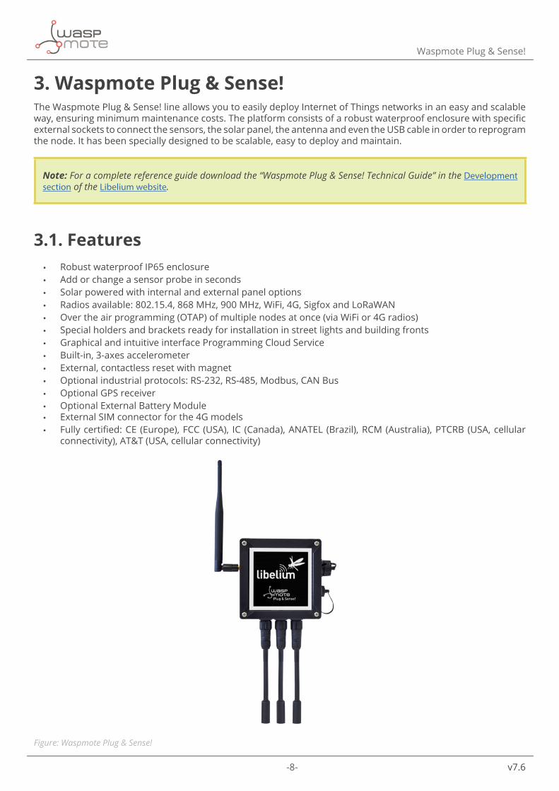
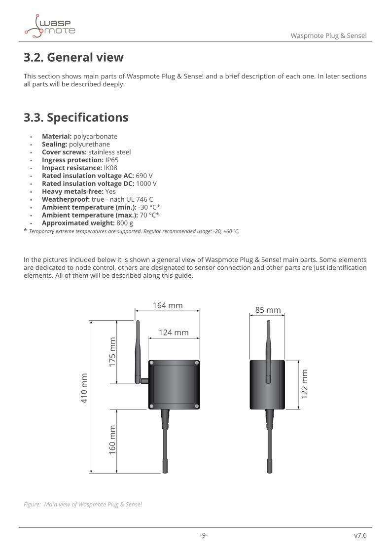
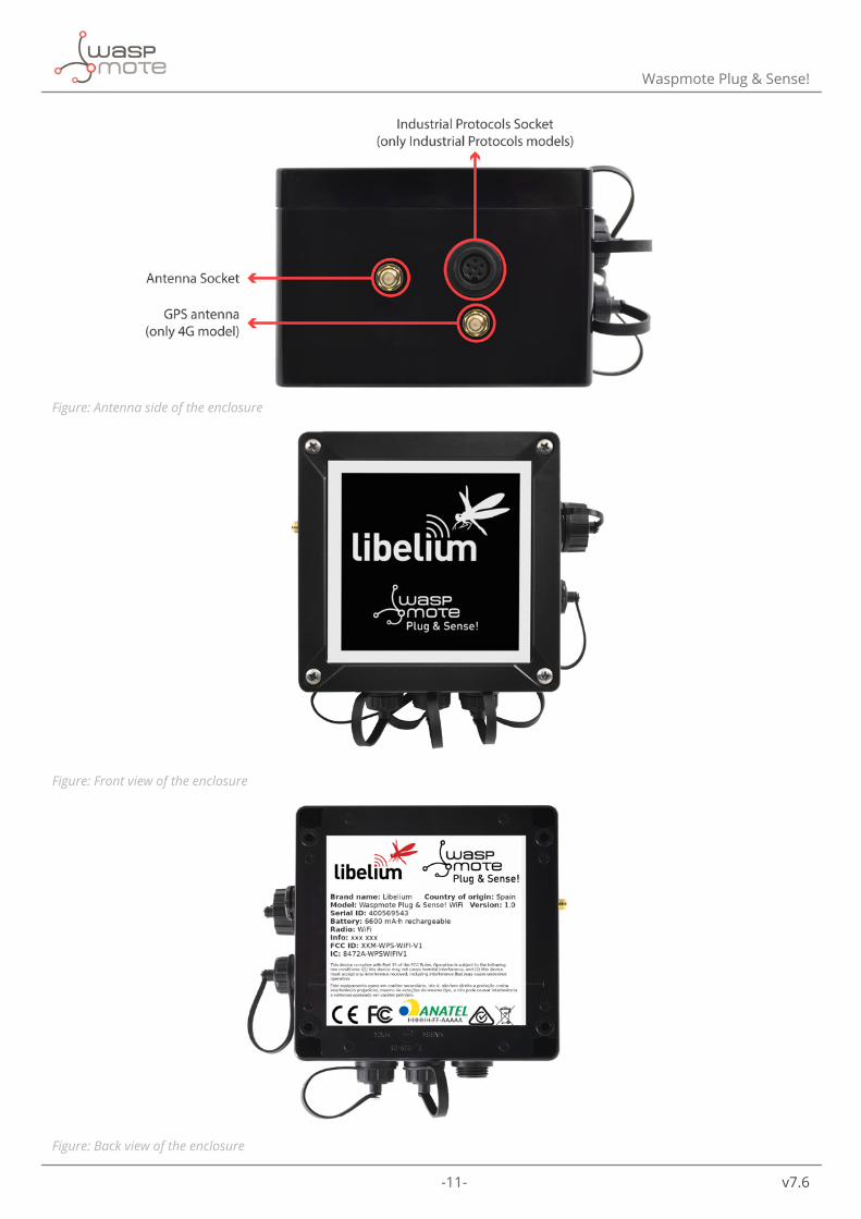
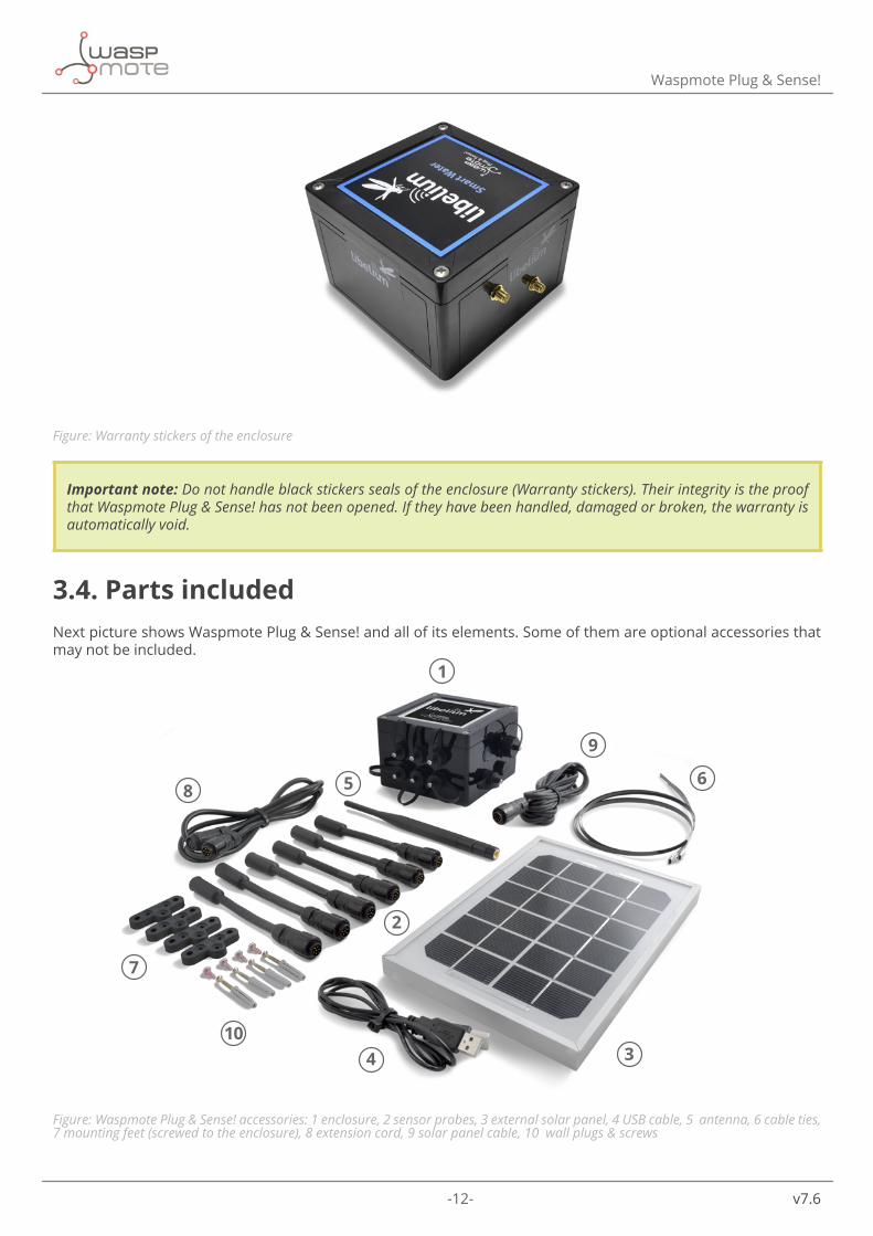
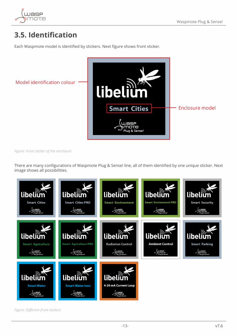
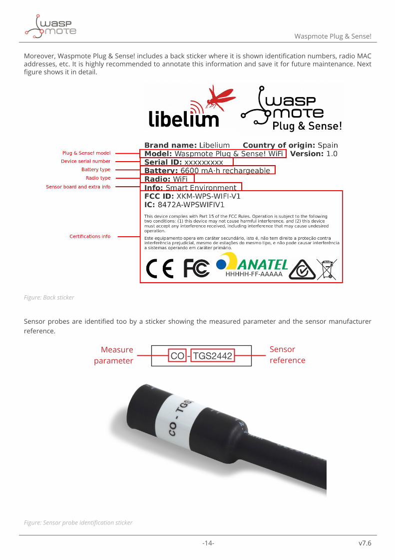
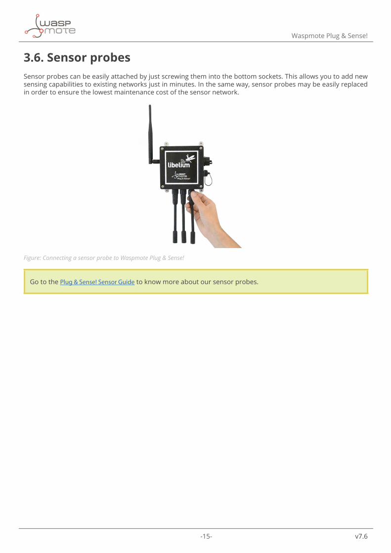
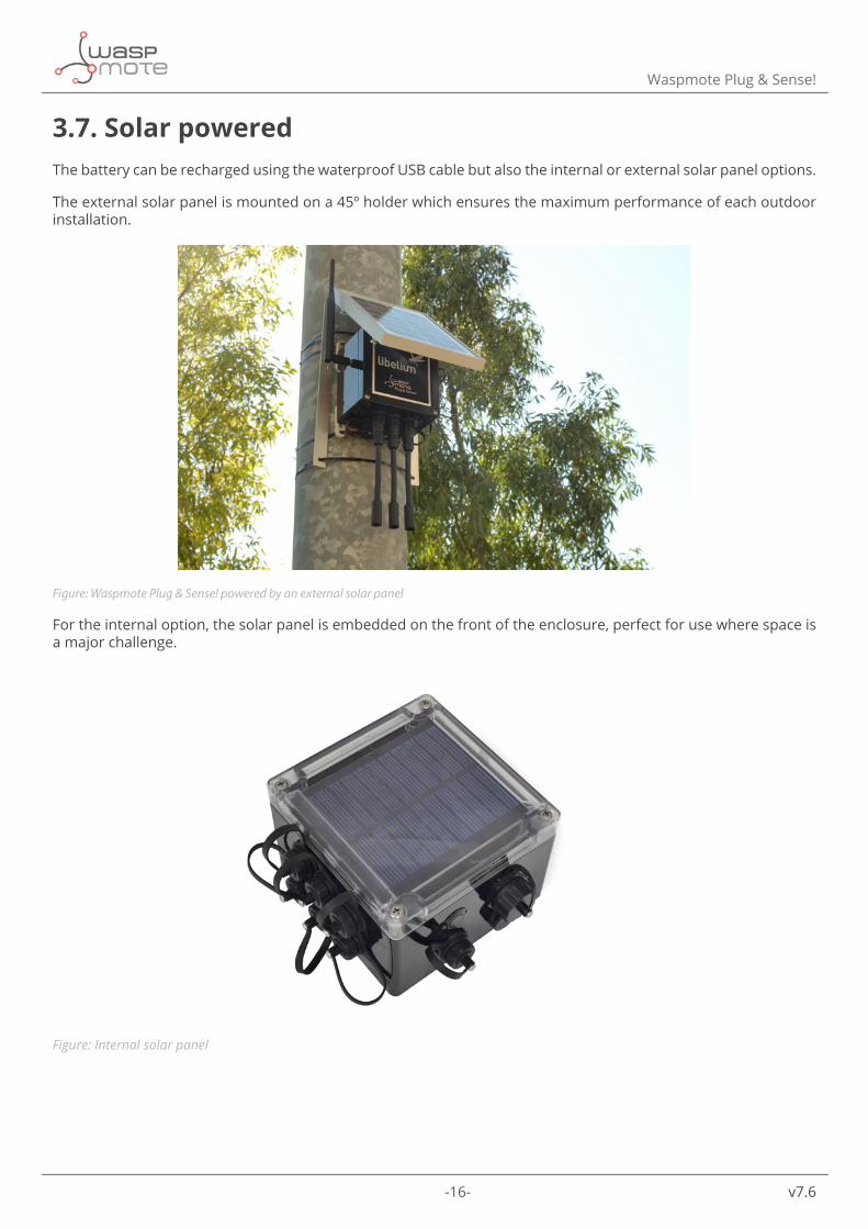
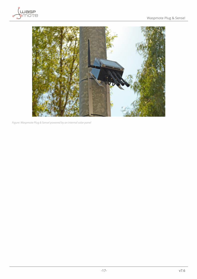
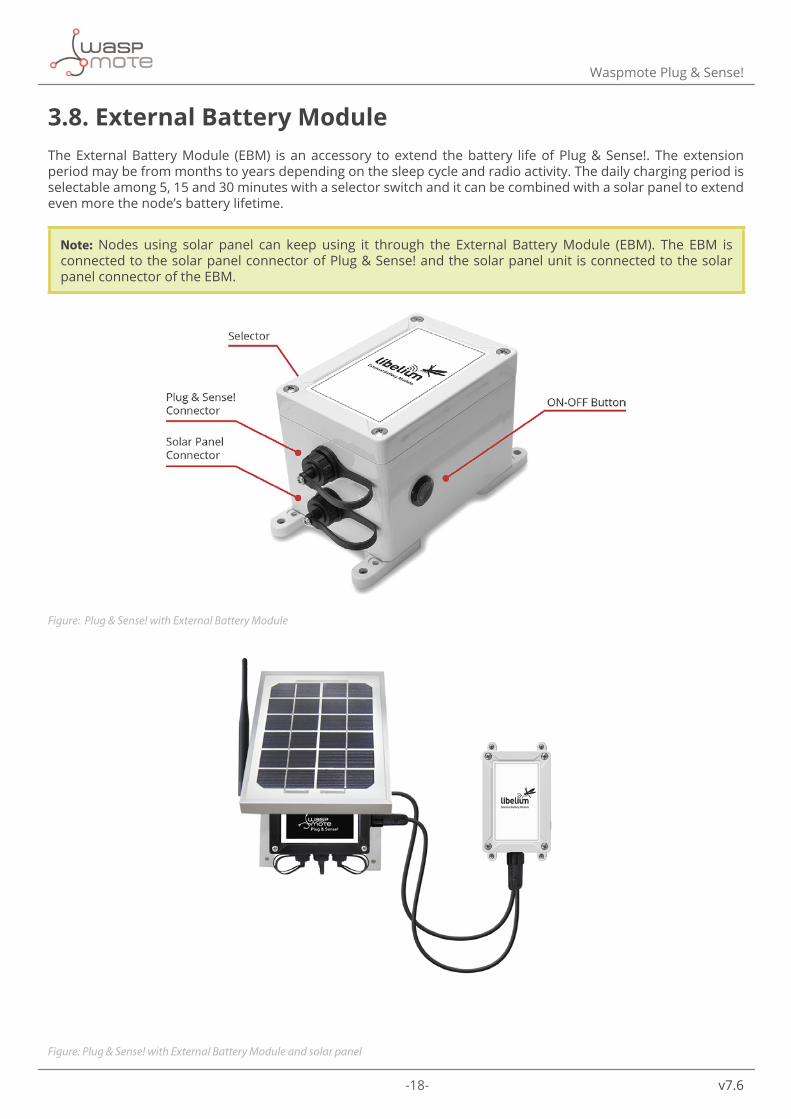
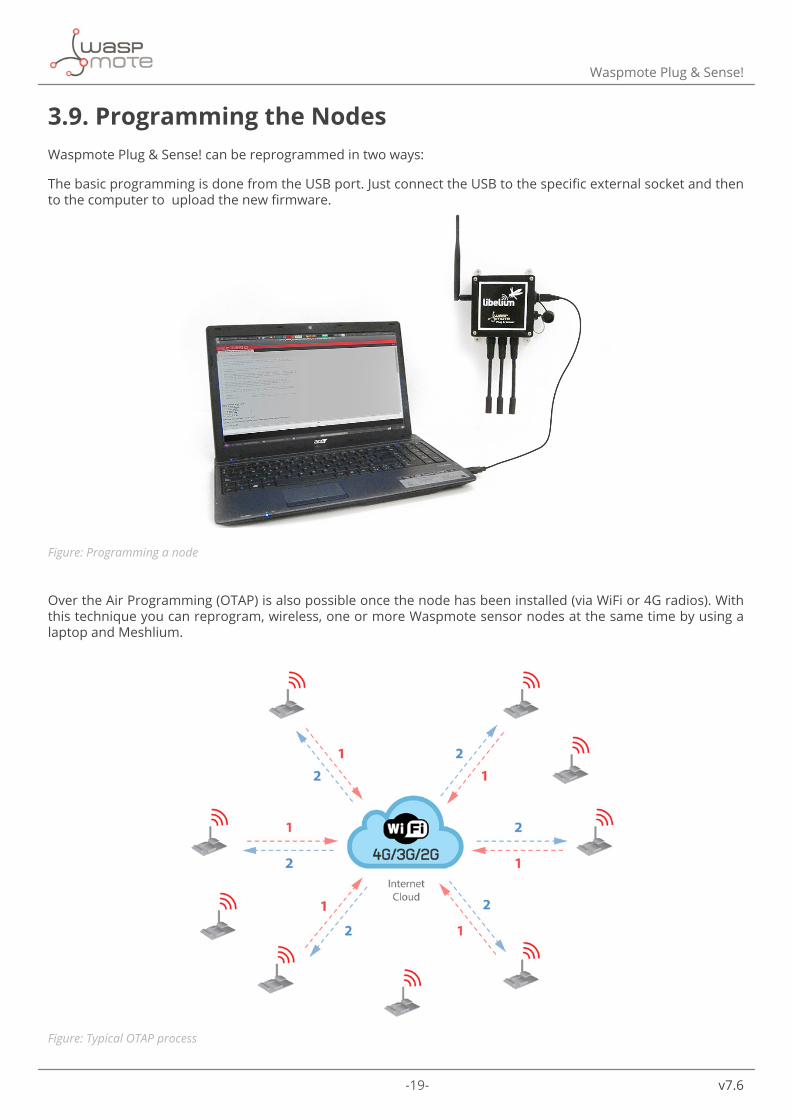
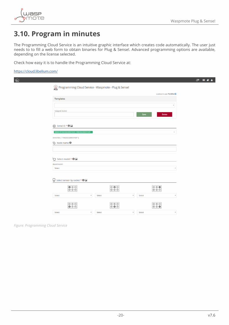
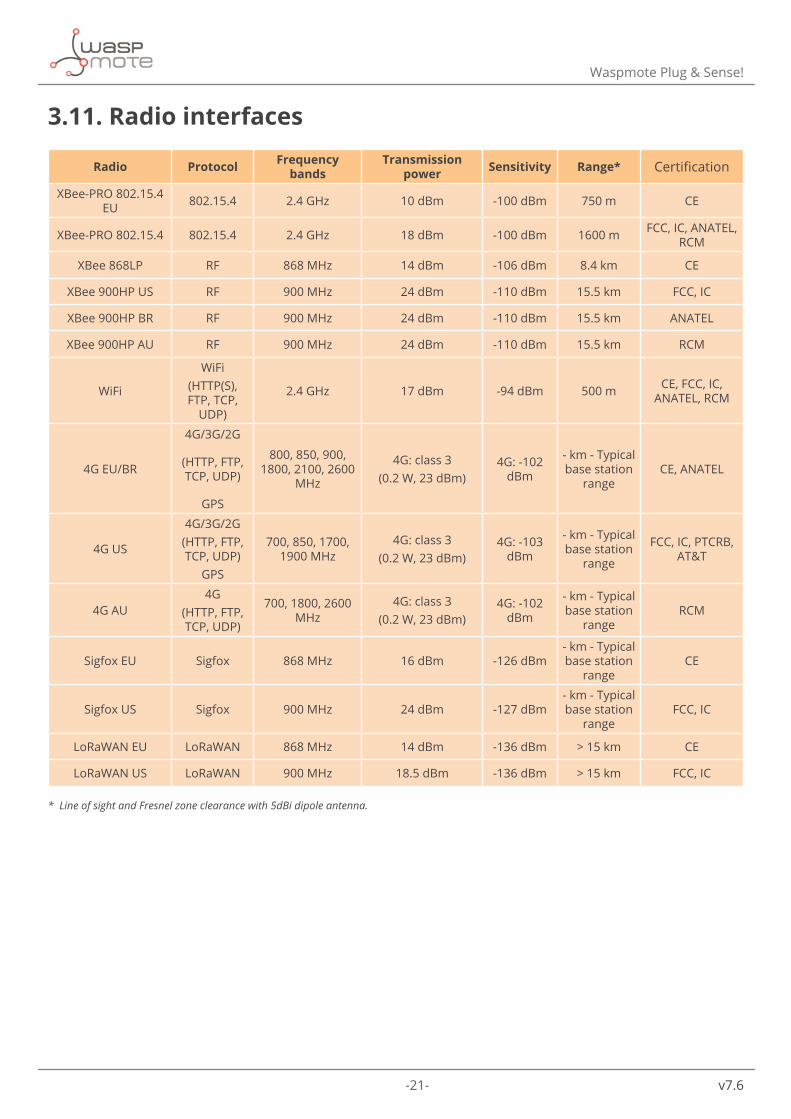
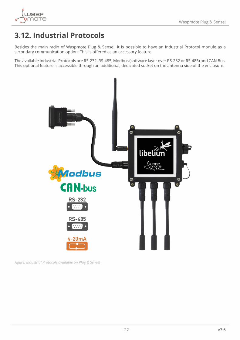
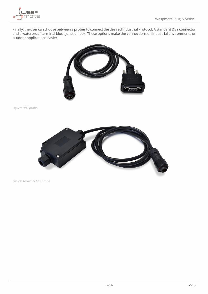
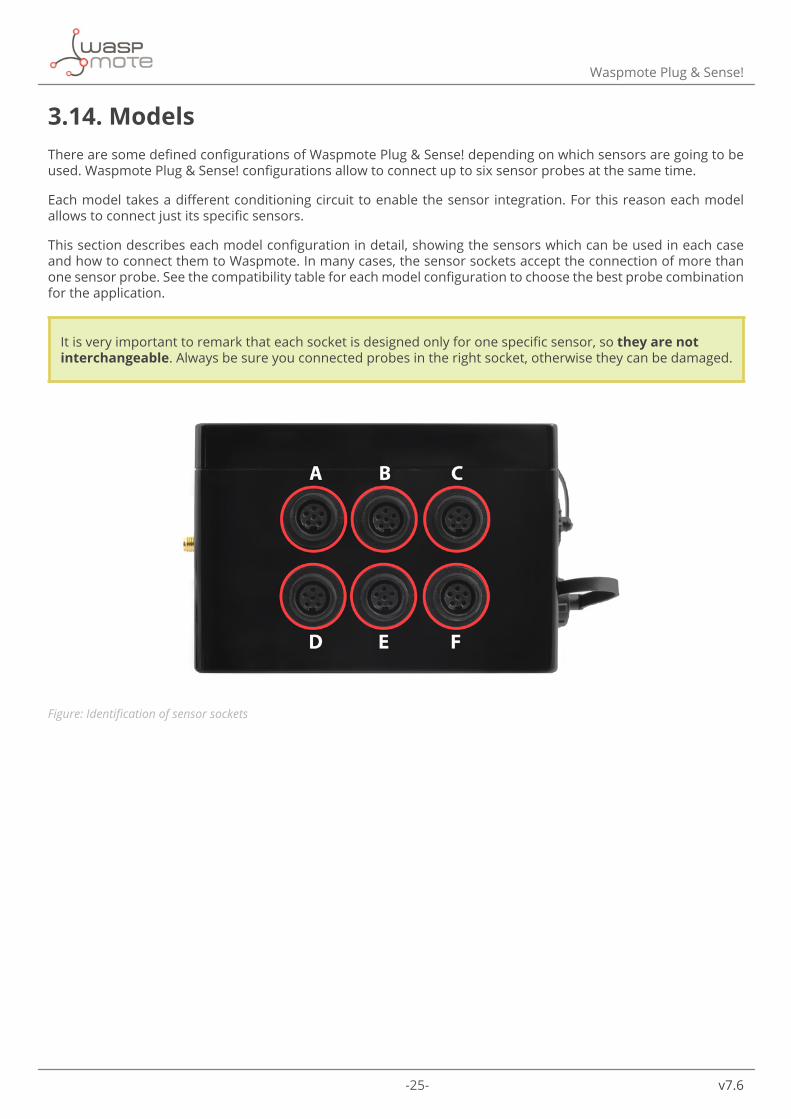
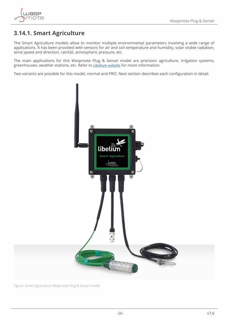
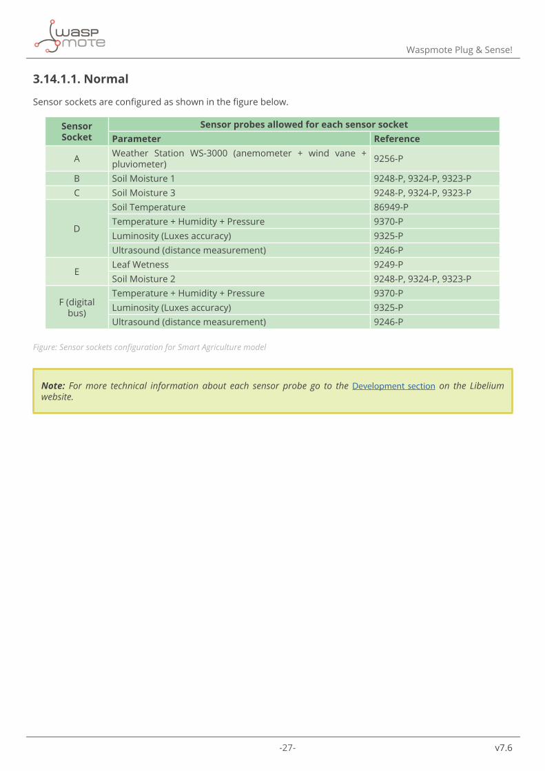
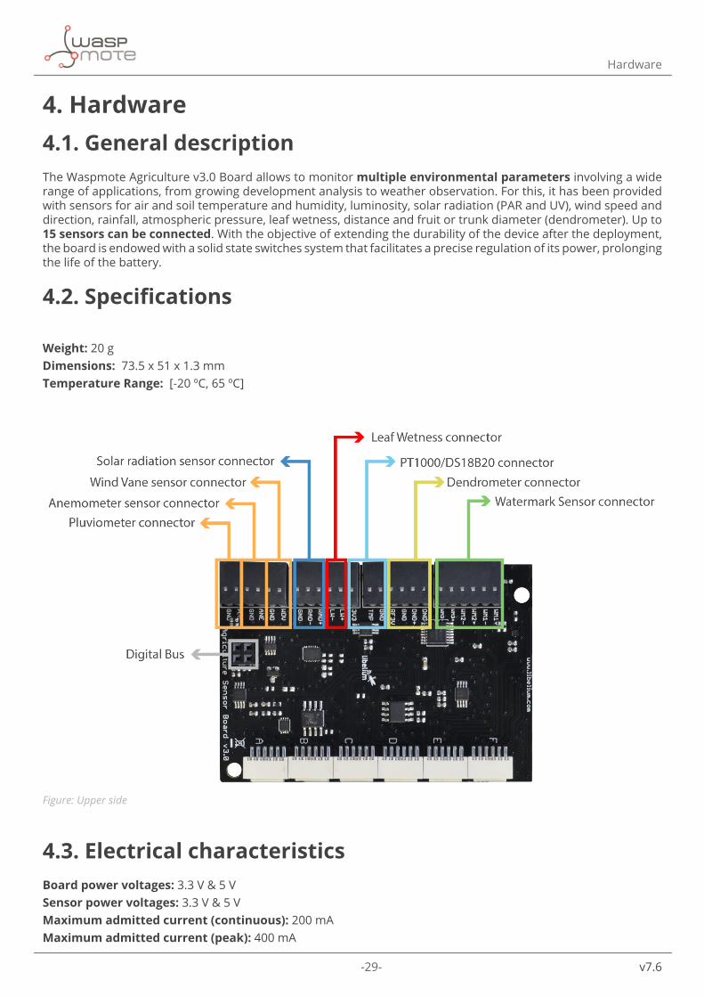
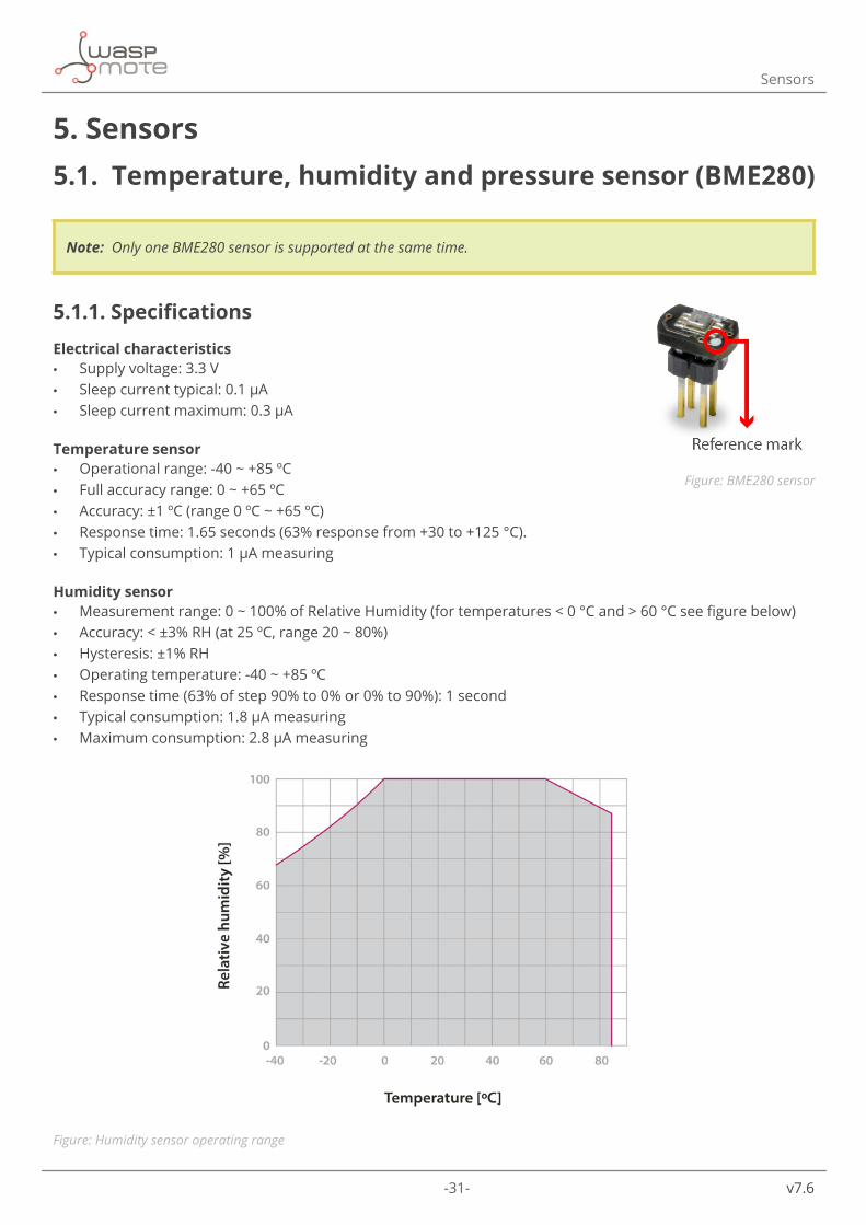
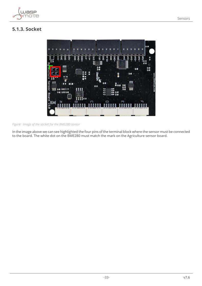
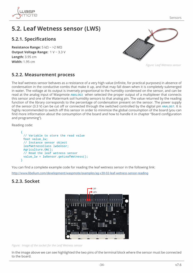
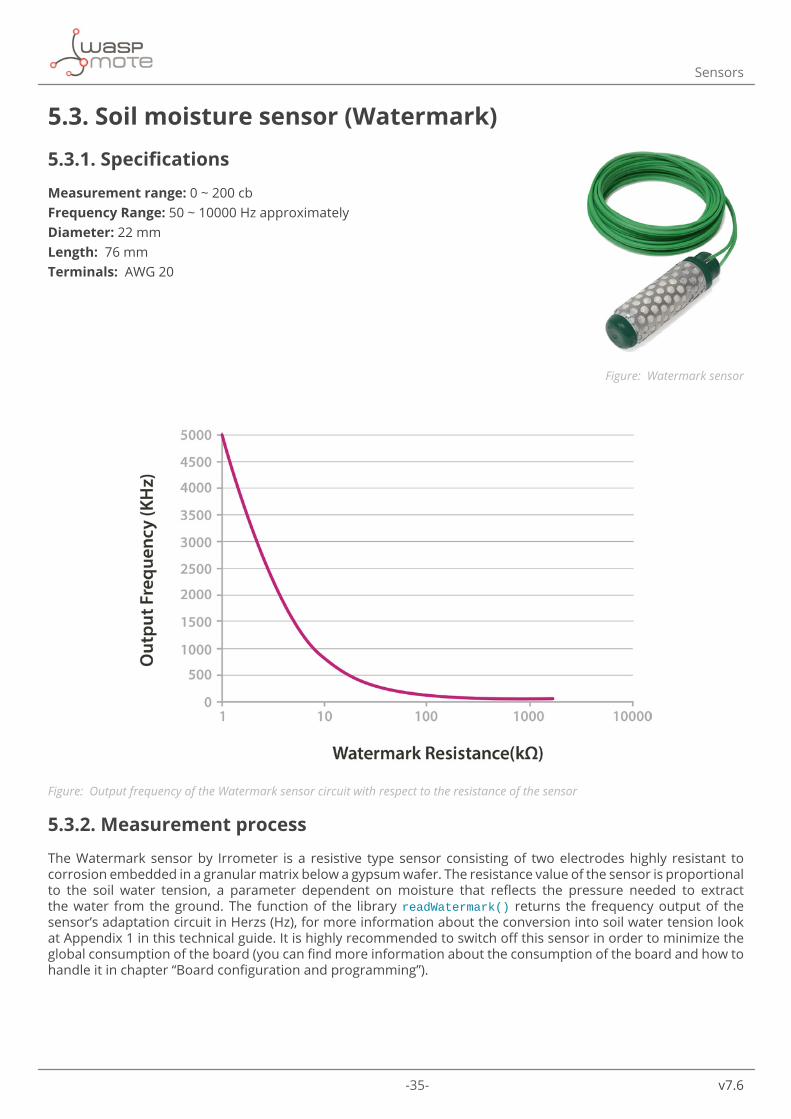
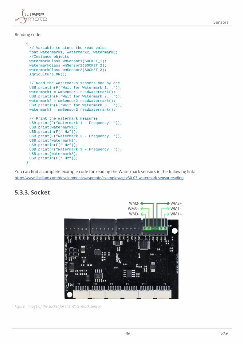
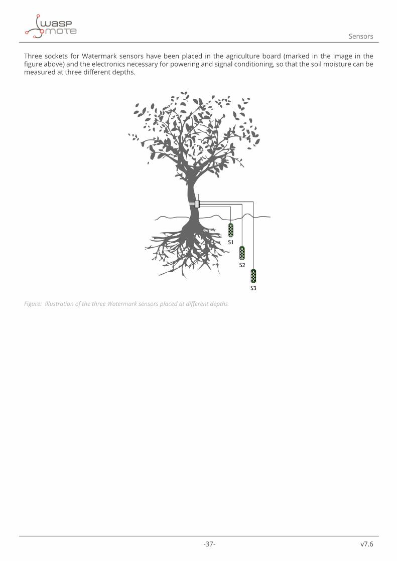
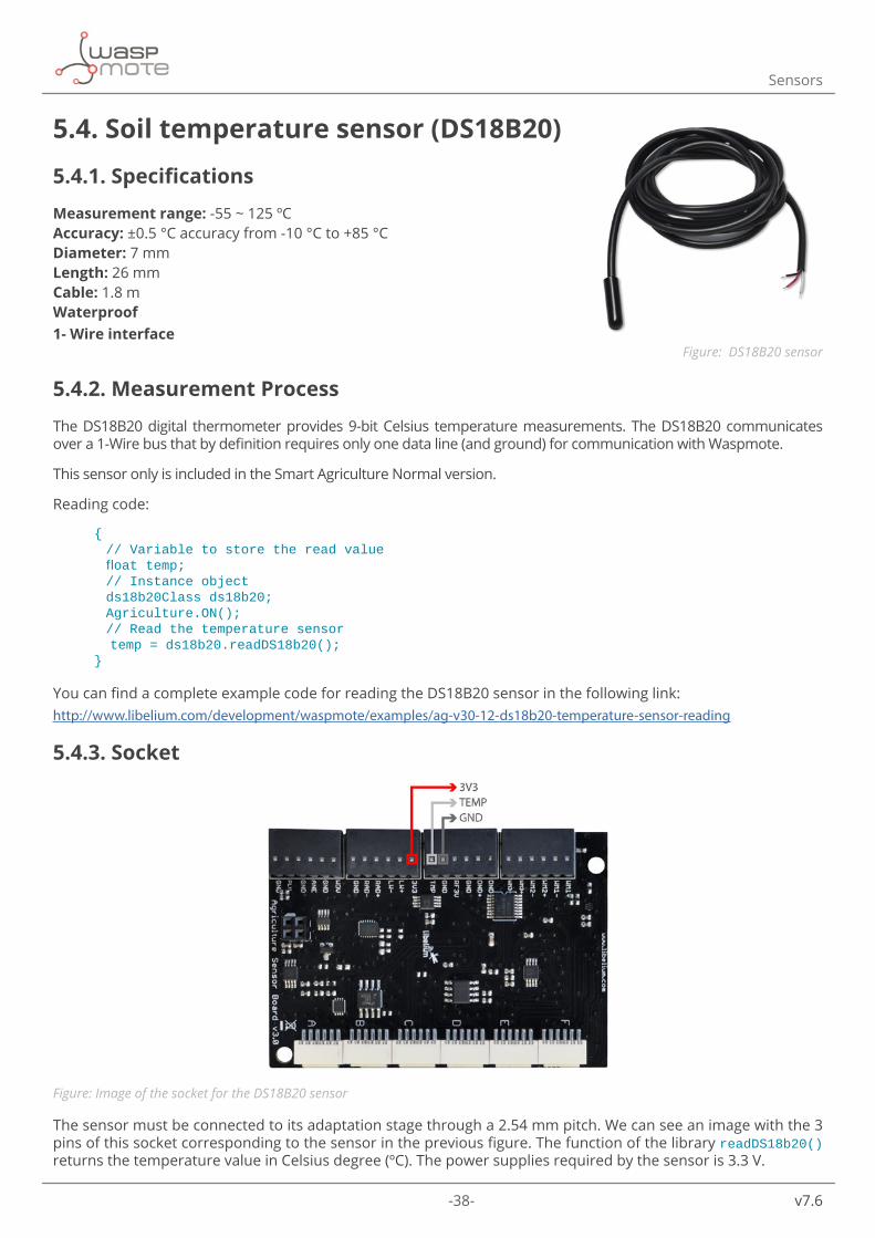
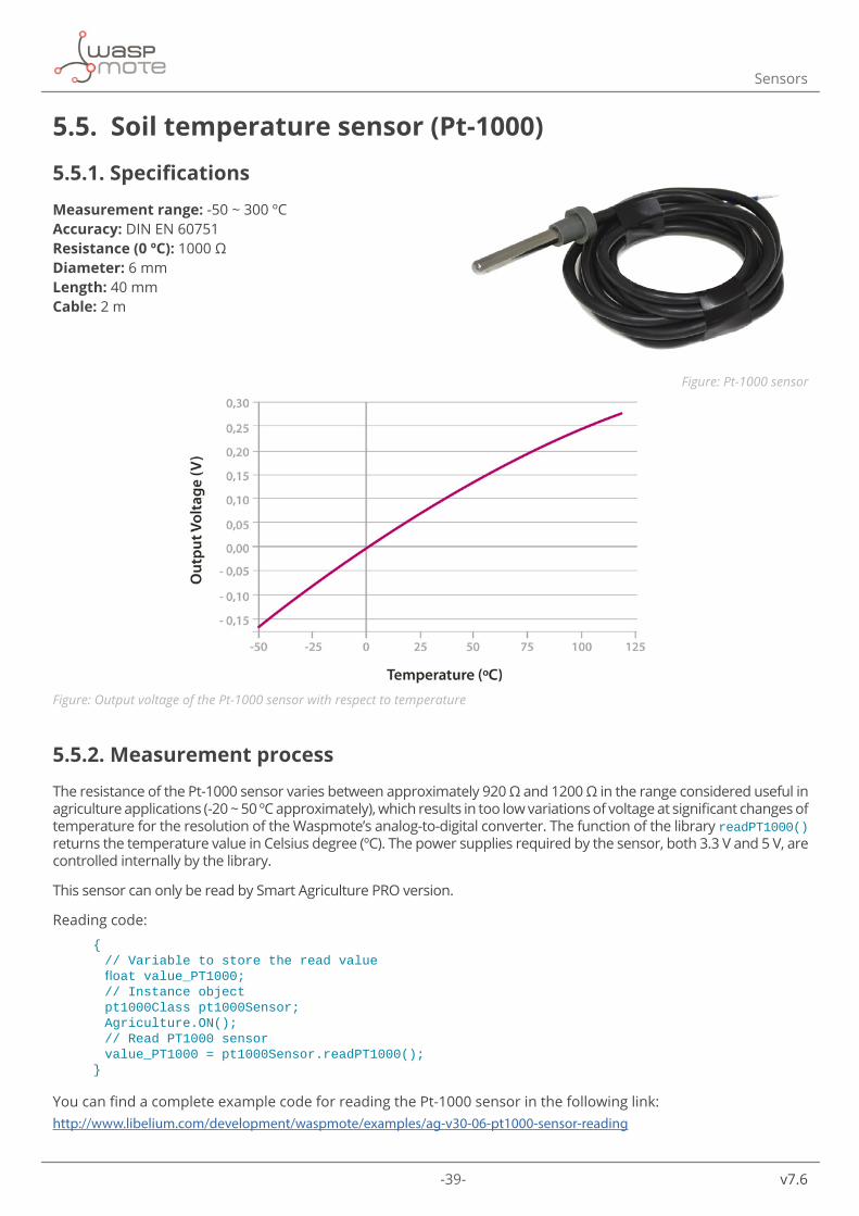
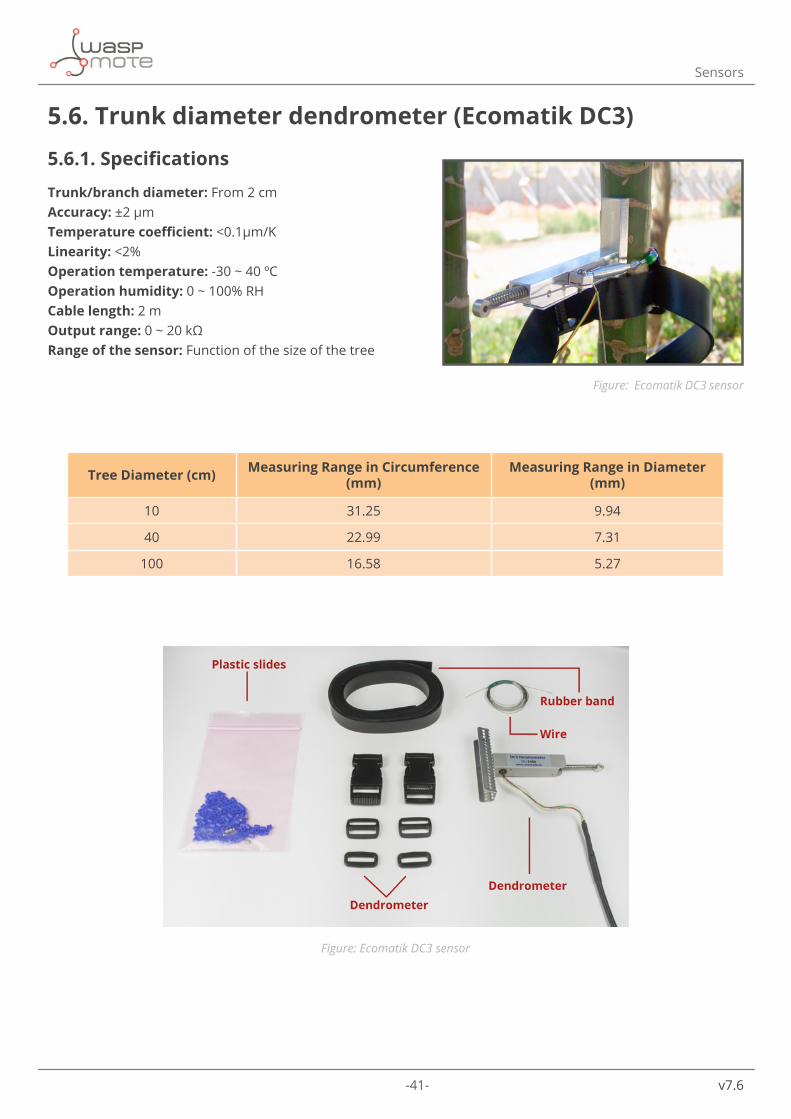
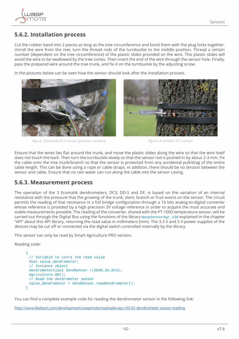
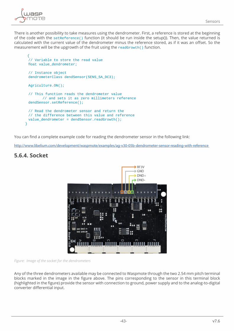
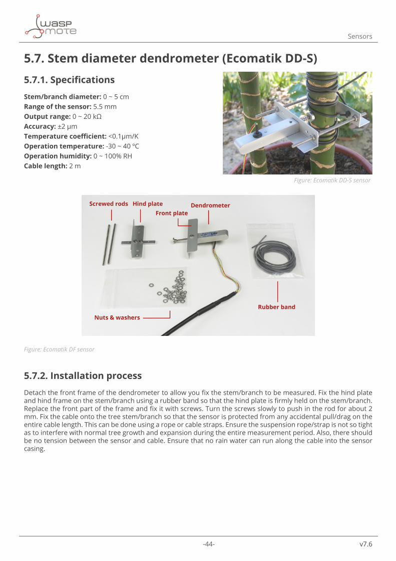
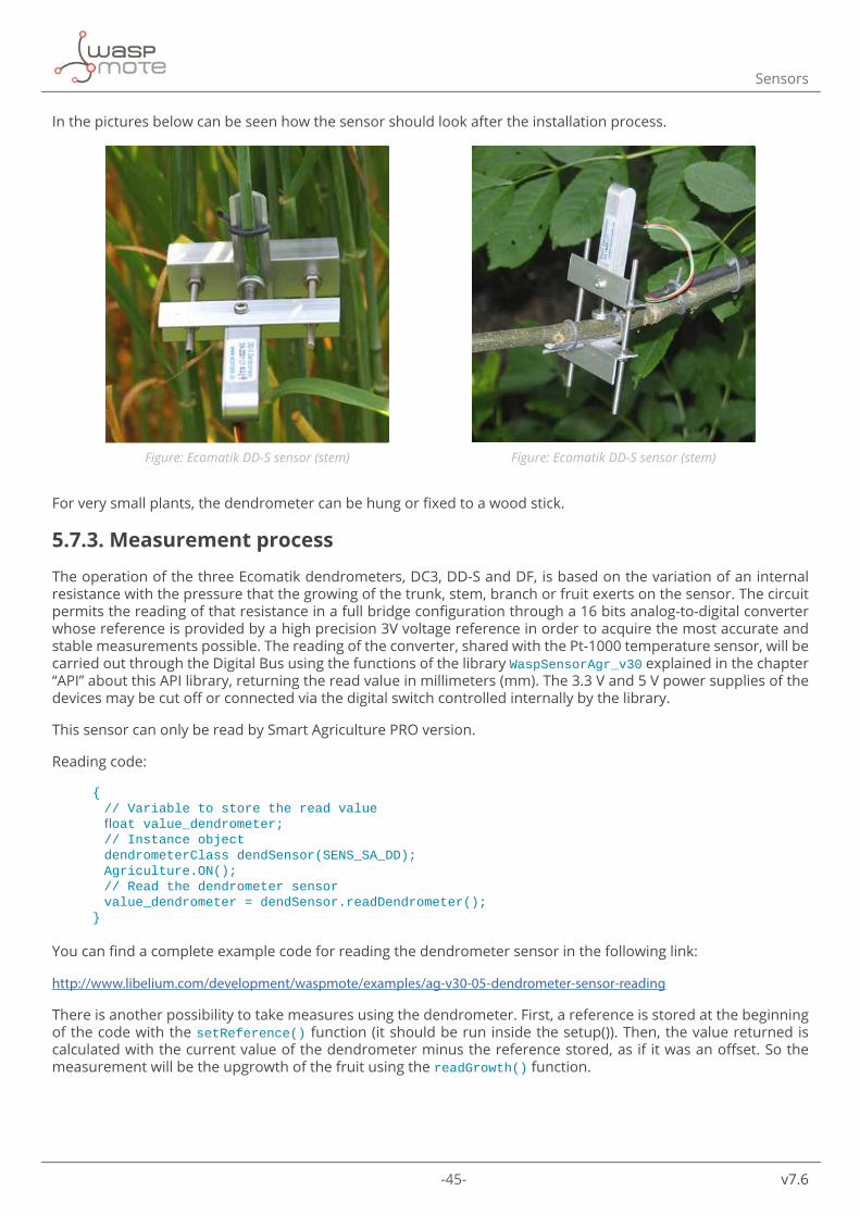
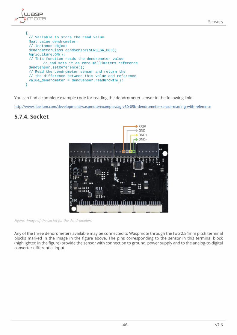
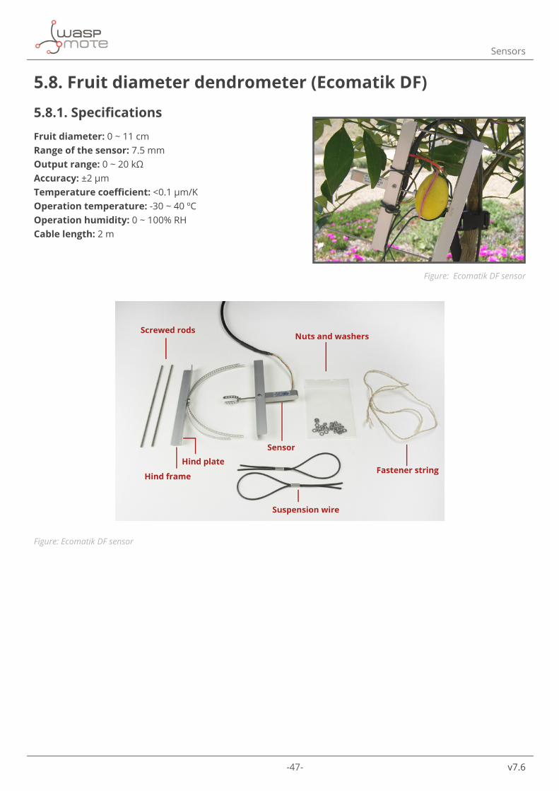
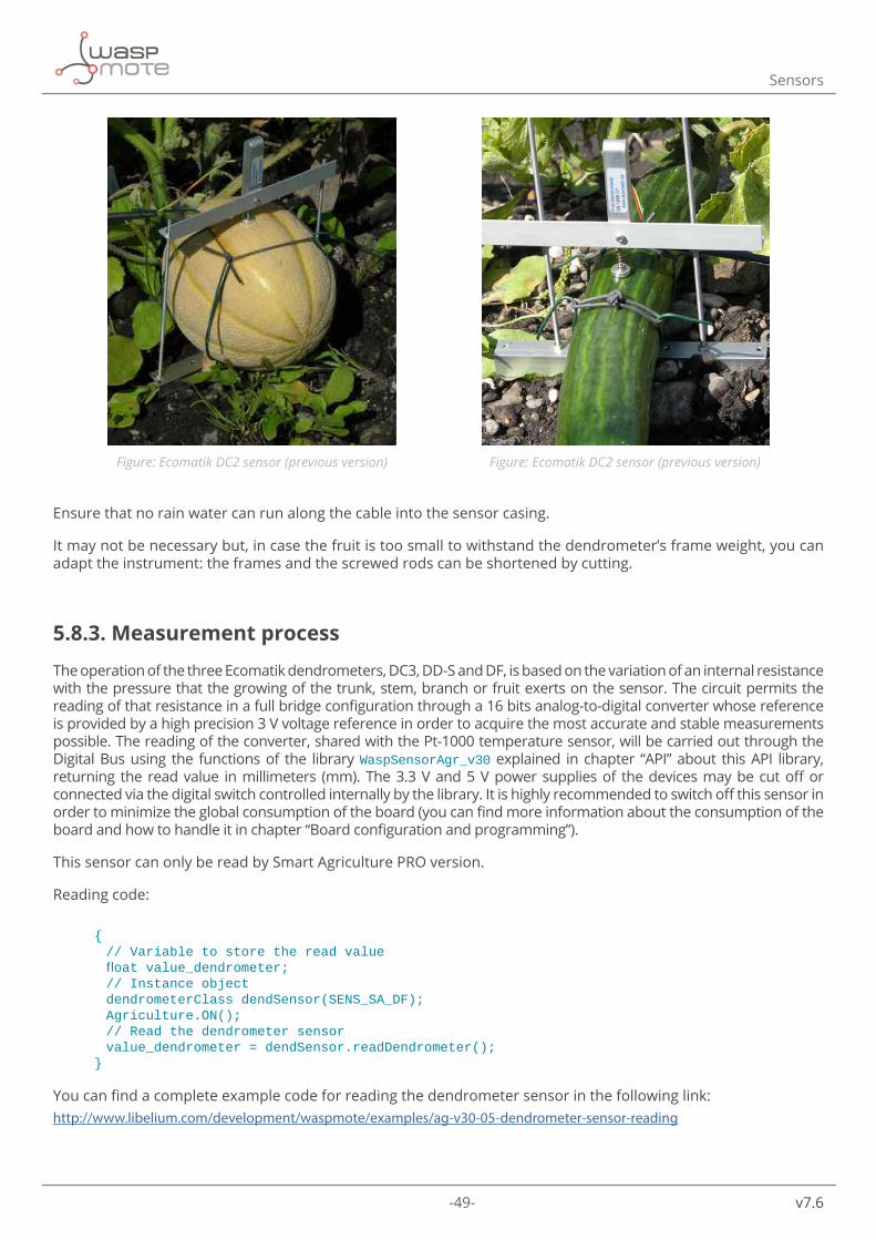
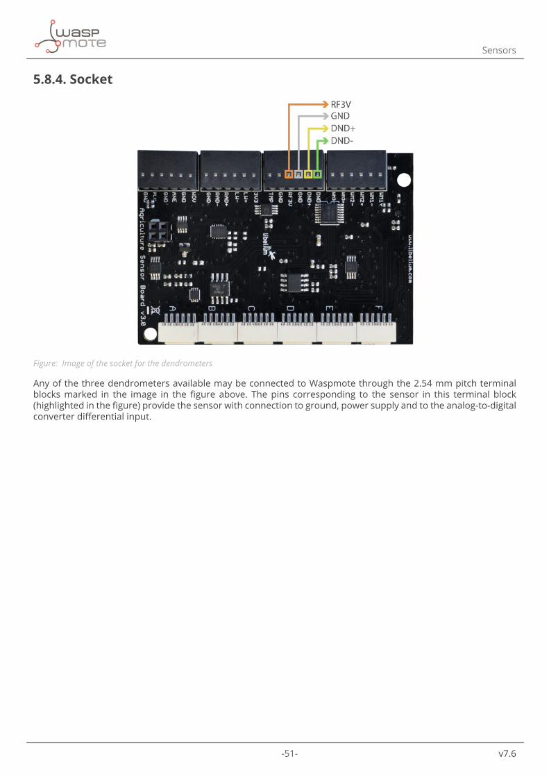
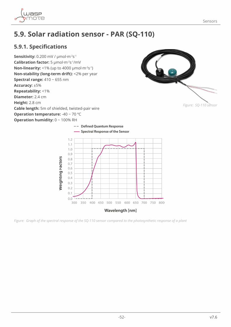
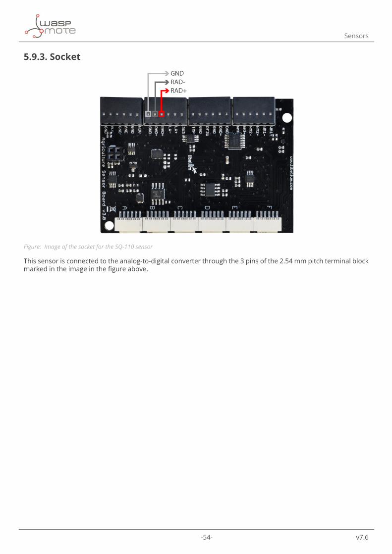
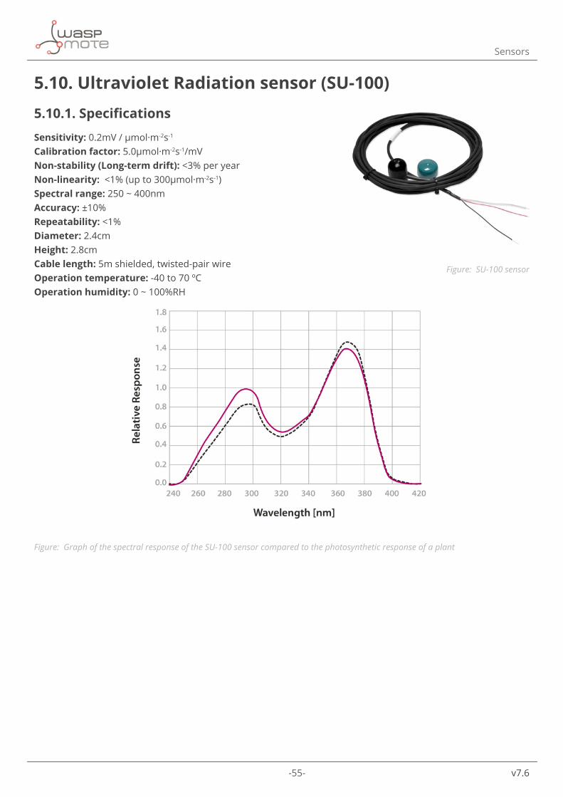
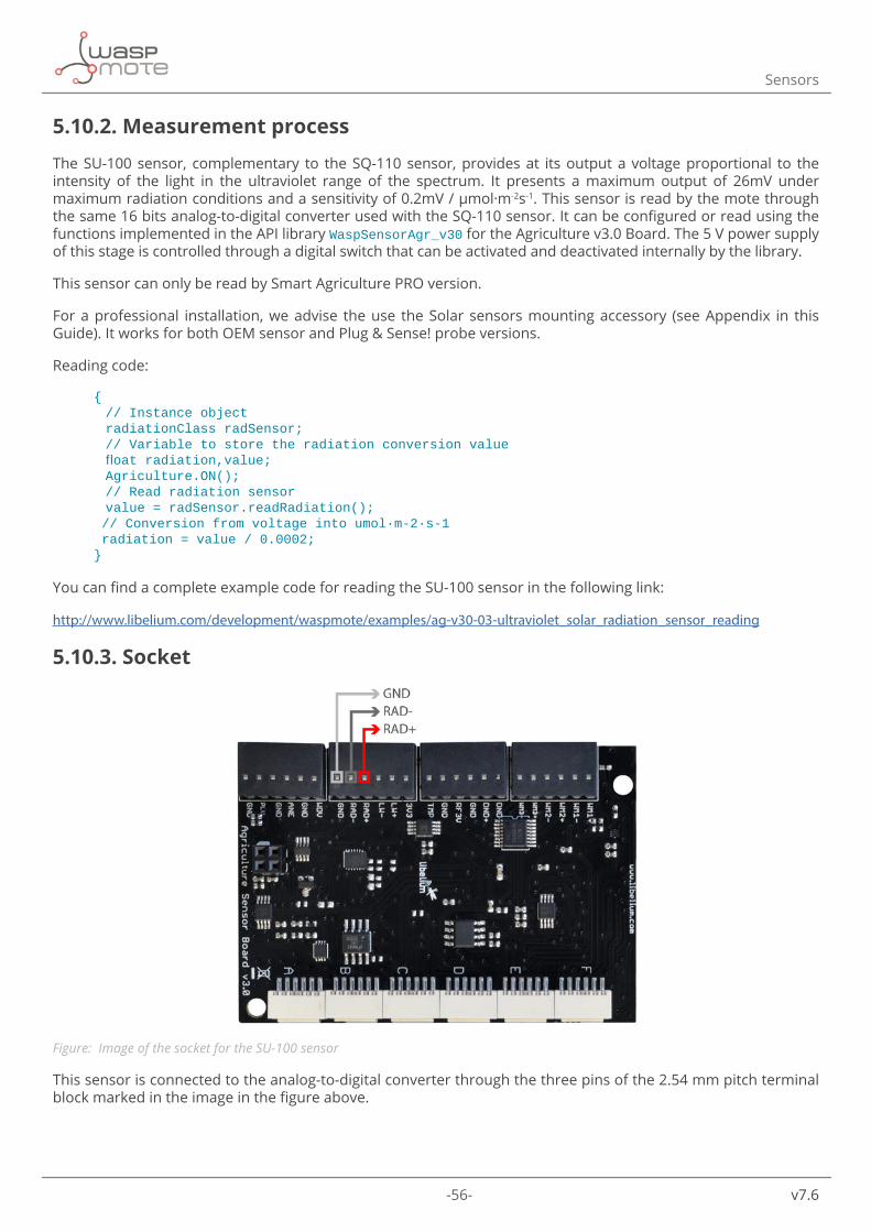
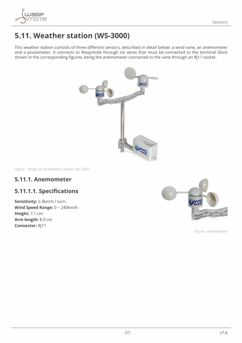
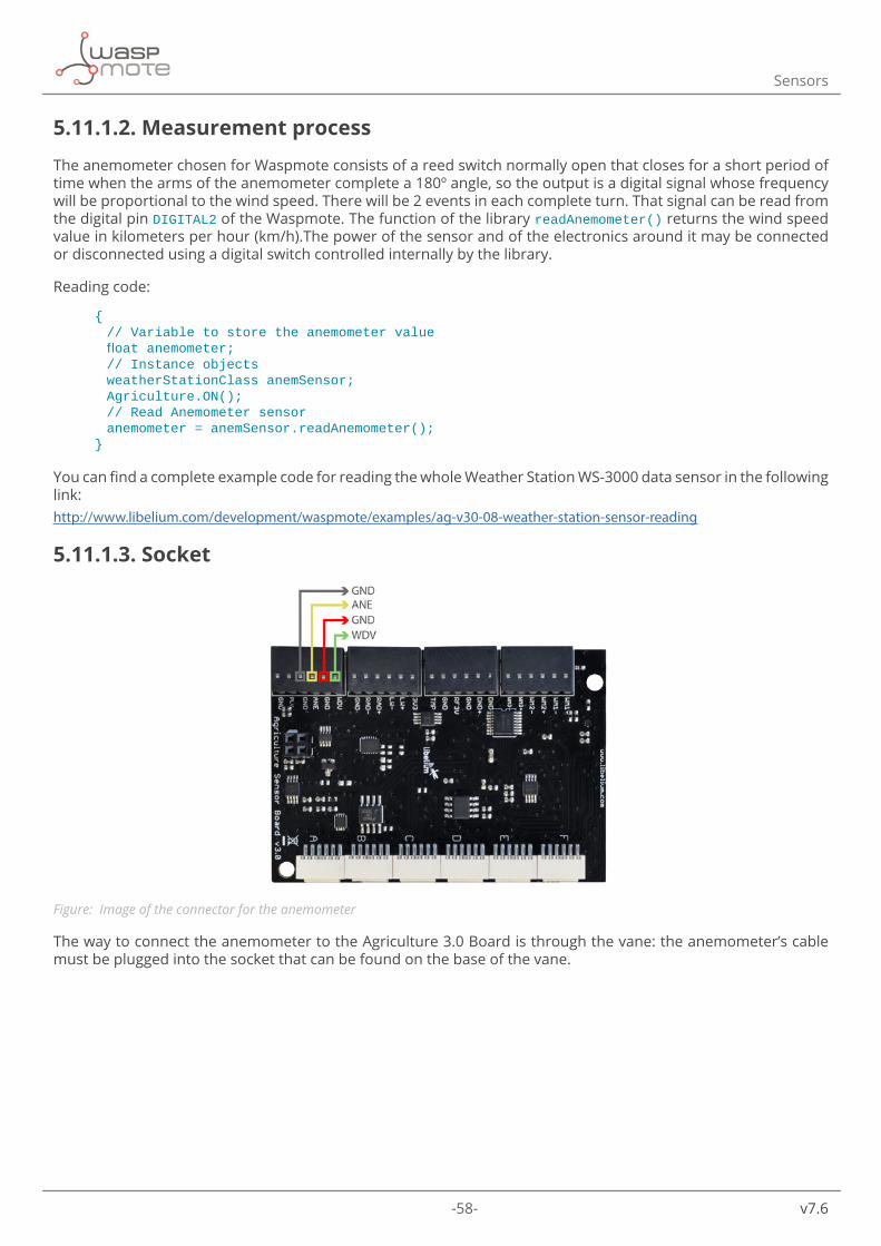
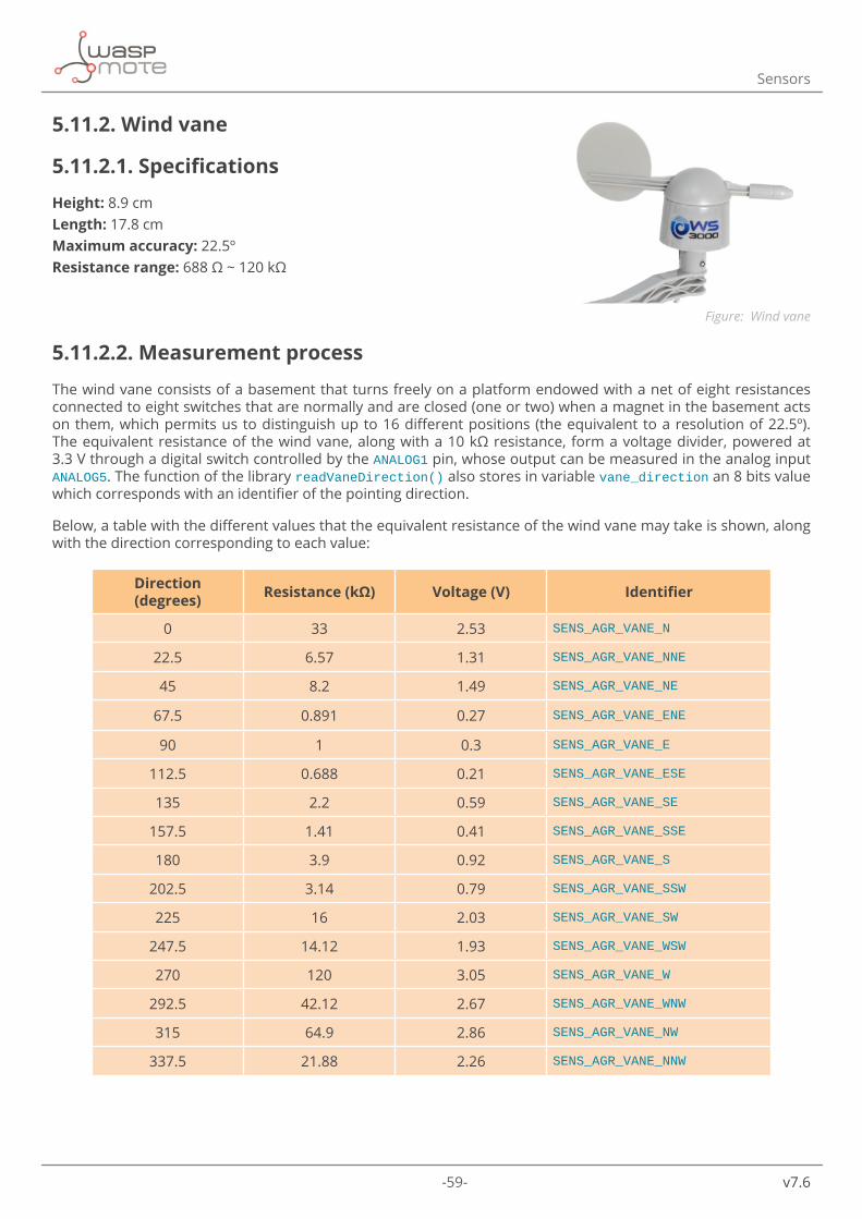
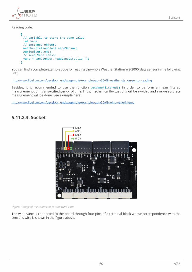
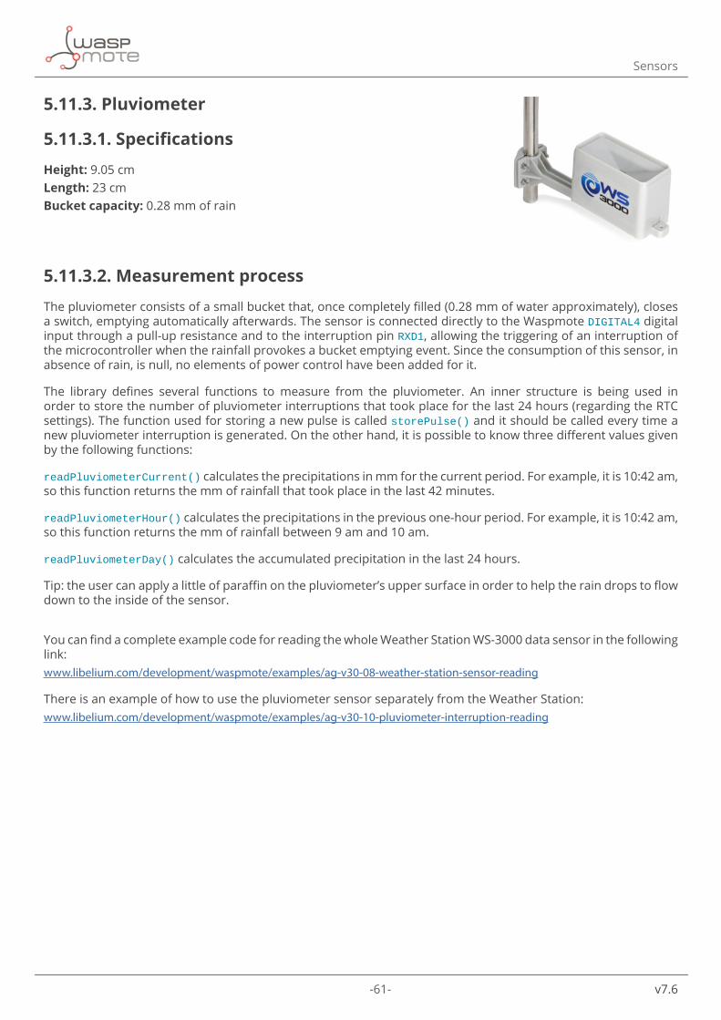
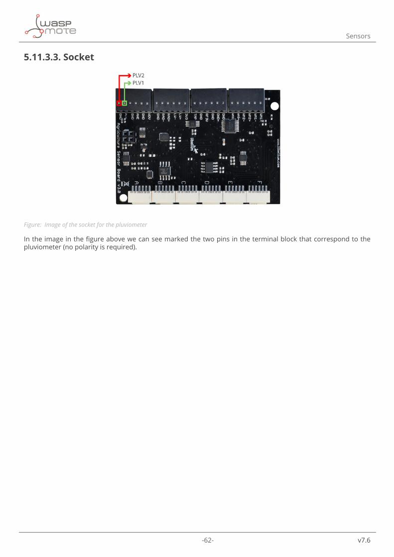
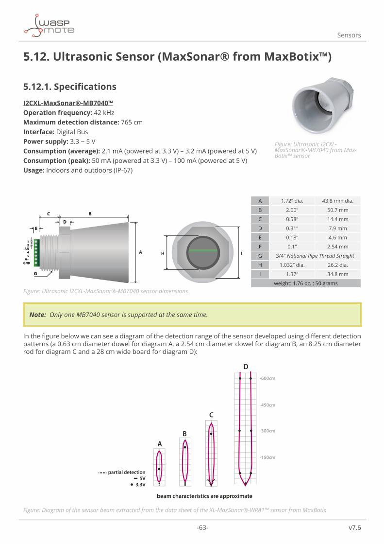
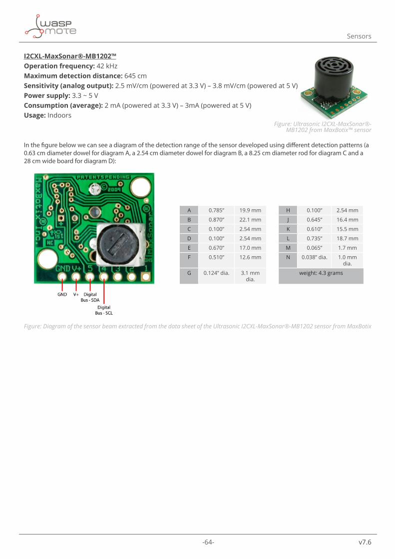
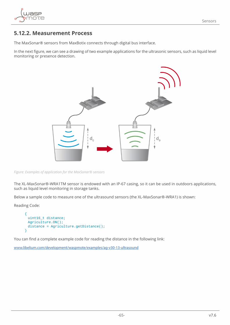
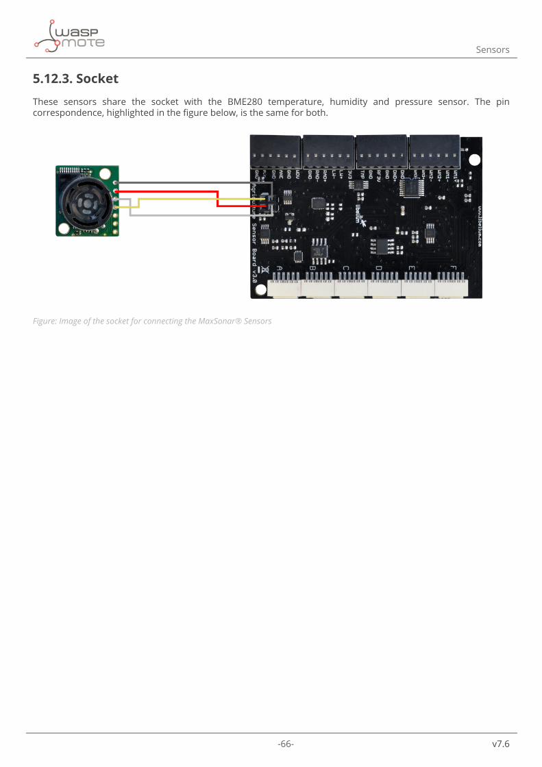
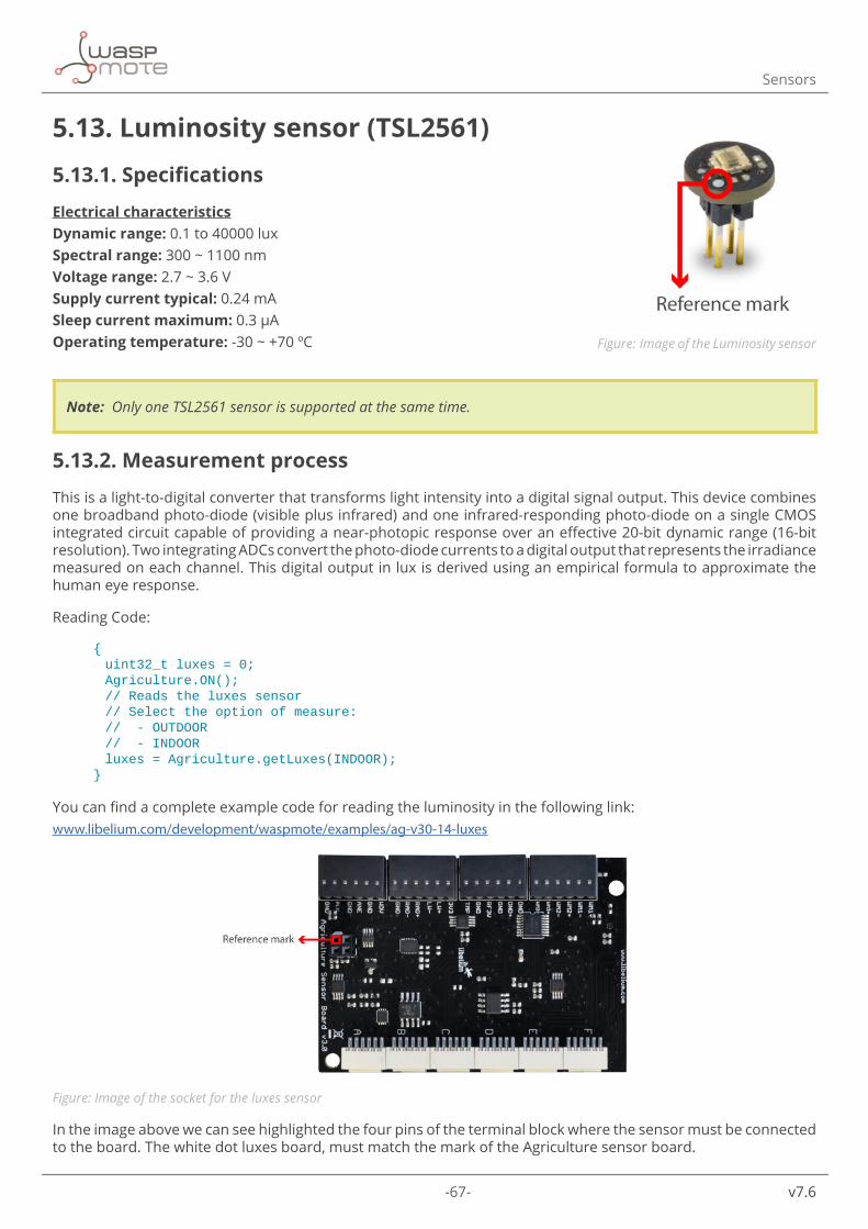
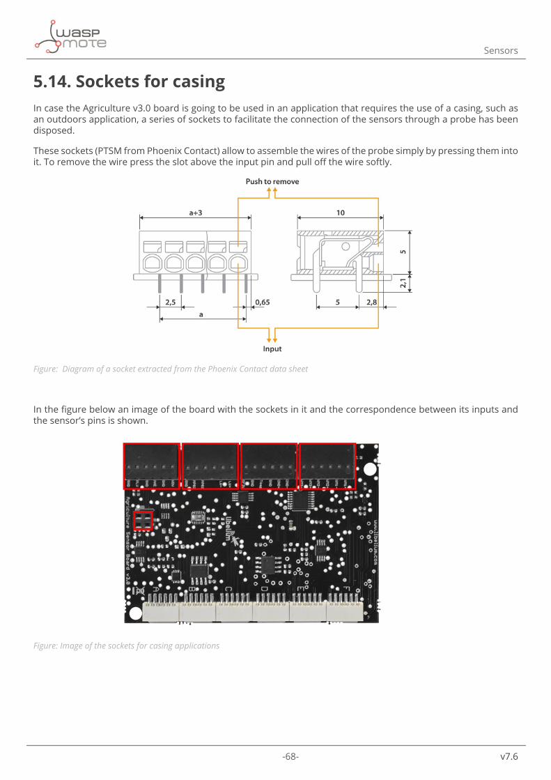
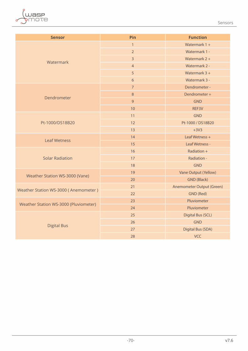
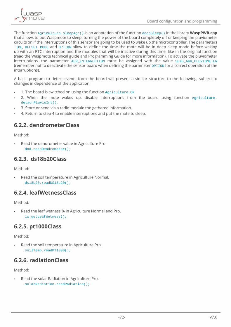
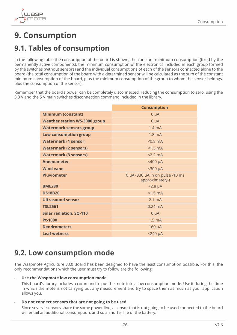
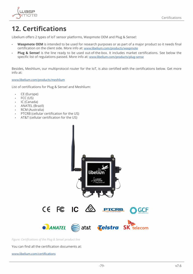
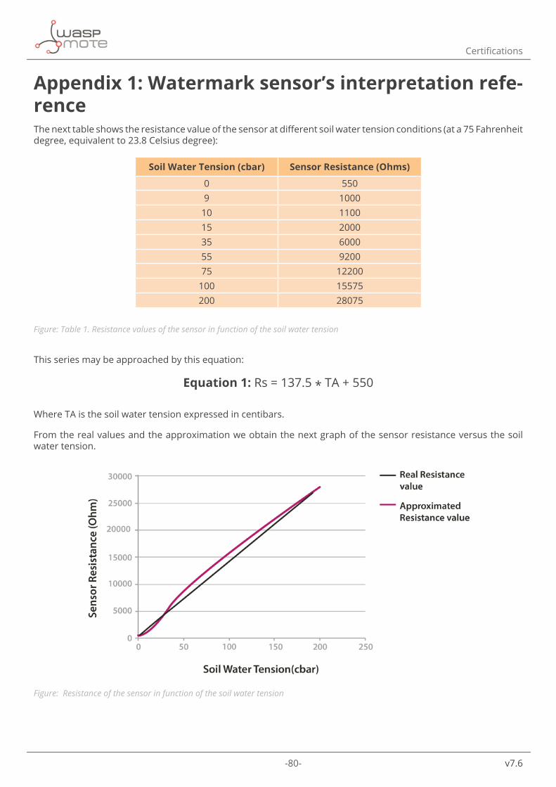
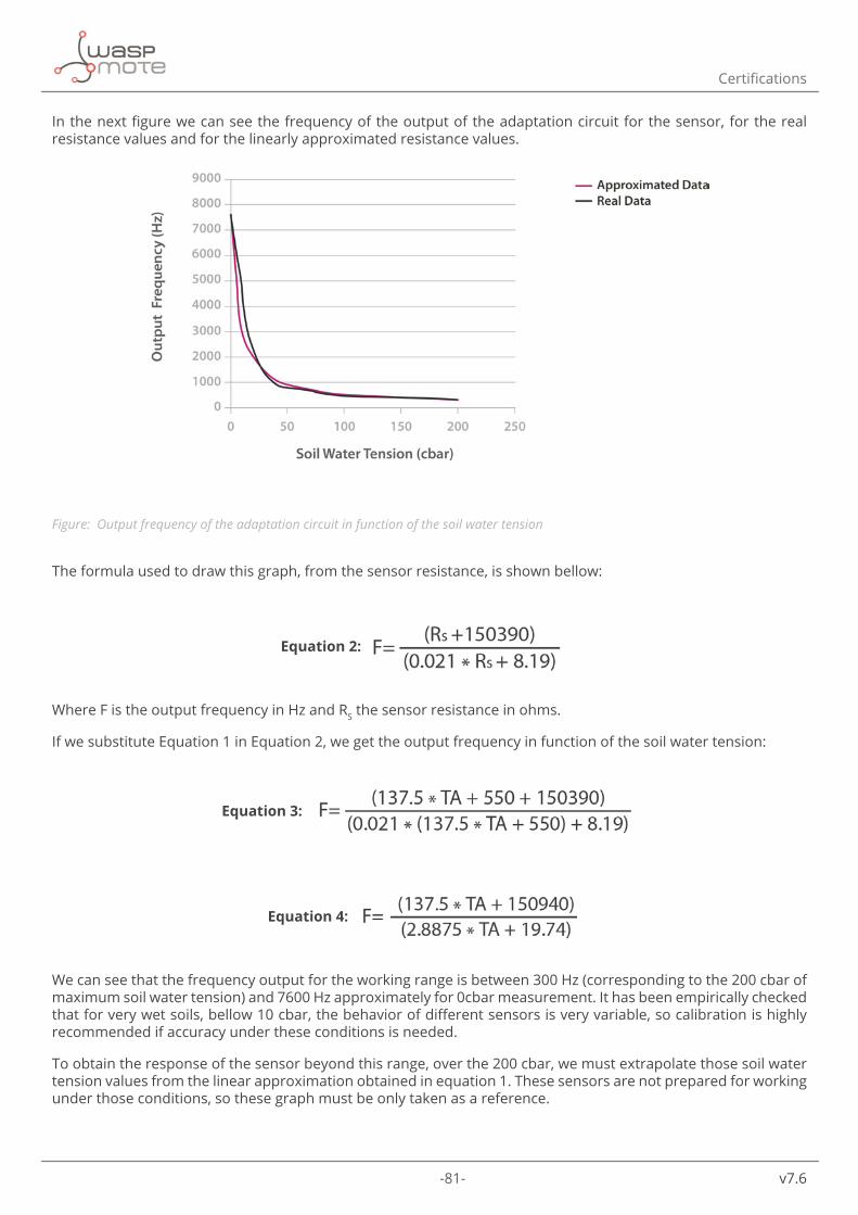
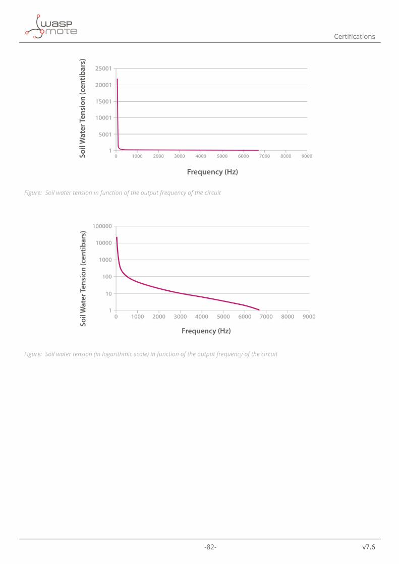
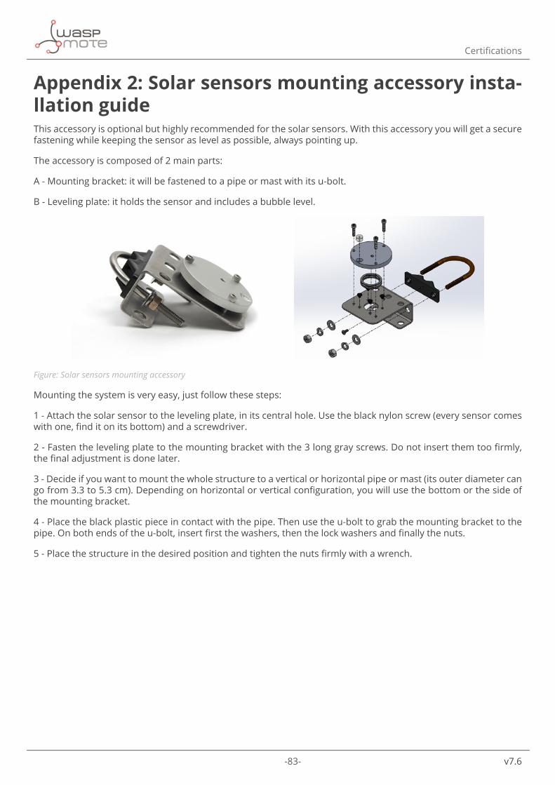
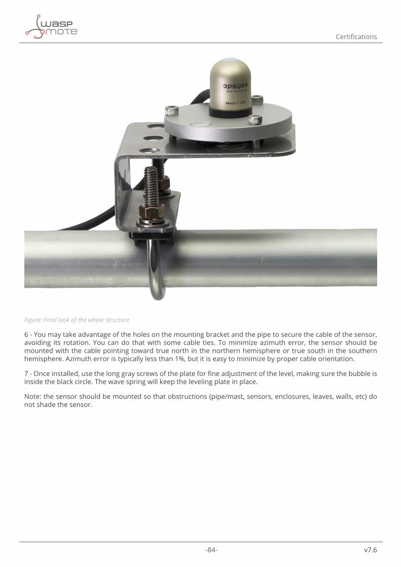