waspmote - libelium
TRANSCRIPT
WaspmoteQuickstart Guide
-2- v4.2
Index
Document version: v4.2 - 08/2013
© Libelium Comunicaciones Distribuidas S.L.
INDEX
1. Introduction ......................................................................................................................................... 3
2. General and safety information ......................................................................................................... 4
3. Waspmote’s Hardware Setup .............................................................................................................. 53.1. Batteries ...........................................................................................................................................................................................53.2. Antennas .........................................................................................................................................................................................63.3. Modules ...........................................................................................................................................................................................63.4. Sensor Boards ................................................................................................................................................................................73.5. SD card .............................................................................................................................................................................................7
4. Waspmote IDE: Download and Installation ....................................................................................... 84.1. Linux .................................................................................................................................................................................................84.2. Windows ..........................................................................................................................................................................................94.3. Mac ....................................................................................................................................................................................................9
5. Receiving Frames from Waspmote ................................................................................................... 105.1. In Waspmote Gateway ............................................................................................................................................................105.2. In Meshlium ................................................................................................................................................................................11
6. Compiling a New Program ................................................................................................................ 12
7. Uploading a New Program to Waspmote......................................................................................... 15
8. How to Use the Developer’s Guides ................................................................................................. 18

-3- v4.2
Introduction
1. IntroductionThe aim of this Guide is to introduce the user to Waspmote in a practical way.
Waspmote is a complex device and a learning process must be completed. Libelium offers many Guides and examples which will help the developer.
The present Guide was created in the hope of helping the developer in the very first steps with Waspmote. We advice to follow this Guide when the user wants to start the learning process. The last chapter will try to plan a learning process, proposing further steps.
-4- v4.2
General and safety information
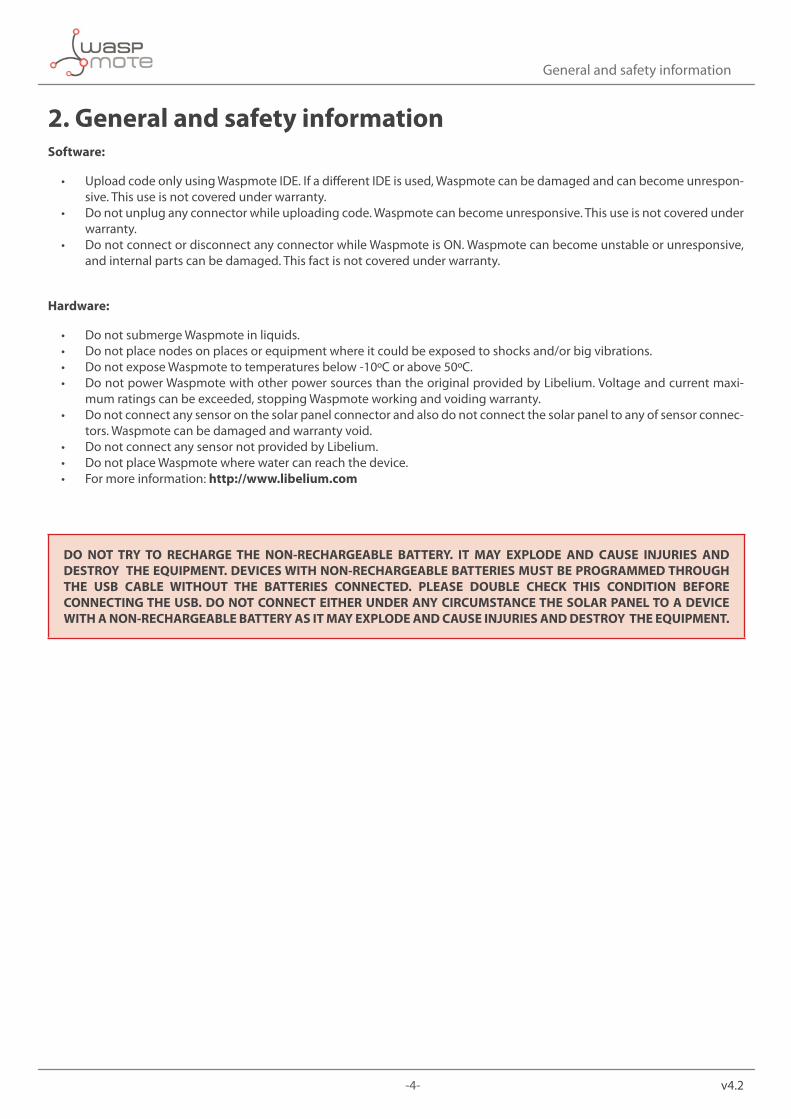
2. General and safety informationSoftware:
• Upload code only using Waspmote IDE. If a different IDE is used, Waspmote can be damaged and can become unrespon-sive. This use is not covered under warranty.
• Do not unplug any connector while uploading code. Waspmote can become unresponsive. This use is not covered under warranty.
• Do not connect or disconnect any connector while Waspmote is ON. Waspmote can become unstable or unresponsive, and internal parts can be damaged. This fact is not covered under warranty.
Hardware:
• Do not submerge Waspmote in liquids. • Do not place nodes on places or equipment where it could be exposed to shocks and/or big vibrations. • Do not expose Waspmote to temperatures below -10ºC or above 50ºC. • Do not power Waspmote with other power sources than the original provided by Libelium. Voltage and current maxi-
mum ratings can be exceeded, stopping Waspmote working and voiding warranty. • Do not connect any sensor on the solar panel connector and also do not connect the solar panel to any of sensor connec-
tors. Waspmote can be damaged and warranty void. • Do not connect any sensor not provided by Libelium. • Do not place Waspmote where water can reach the device. • For more information: http://www.libelium.com
DO NOT TRY TO RECHARGE THE NON-RECHARGEABLE BATTERY. IT MAY EXPLODE AND CAUSE INJURIES AND DESTROY THE EQUIPMENT. DEVICES WITH NON-RECHARGEABLE BATTERIES MUST BE PROGRAMMED THROUGH THE USB CABLE WITHOUT THE BATTERIES CONNECTED. PLEASE DOUBLE CHECK THIS CONDITION BEFORE CONNECTING THE USB. DO NOT CONNECT EITHER UNDER ANY CIRCUMSTANCE THE SOLAR PANEL TO A DEVICE WITH A NON-RECHARGEABLE BATTERY AS IT MAY EXPLODE AND CAUSE INJURIES AND DESTROY THE EQUIPMENT.

-5- v4.2
Waspmote’s Hardware Setup
3. Waspmote’s Hardware SetupCheck the next basic points about the hardware configuration:
3.1. BatteriesConnect the battery to Waspmote. Remember you have to charge the batteries at least for 24h before start using Waspmote.
Figure 1: Connect the battery
DO NOT TRY TO RECHARGE THE NON-RECHARGEABLE BATTERY. IT MAY EXPLODE AND CAUSE INJURIES AND DESTROY THE EQUIPMENT. DEVICES WITH NON-RECHARGEABLE BATTERIES MUST BE PROGRAMMED THROUGH THE USB CABLE WITHOUT THE BATTERIES CONNECTED. PLEASE DOUBLE CHECK THIS CONDITION BEFORE CONNECTING THE USB. DO NOT CONNECT EITHER UNDER ANY CIRCUMSTANCE THE SOLAR PANEL TO A DEVICE WITH A NON-RECHARGEABLE BATTERY AS IT MAY EXPLODE AND CAUSE INJURIES AND DESTROY THE EQUIPMENT.
-6- v4.2
Waspmote’s Hardware Setup
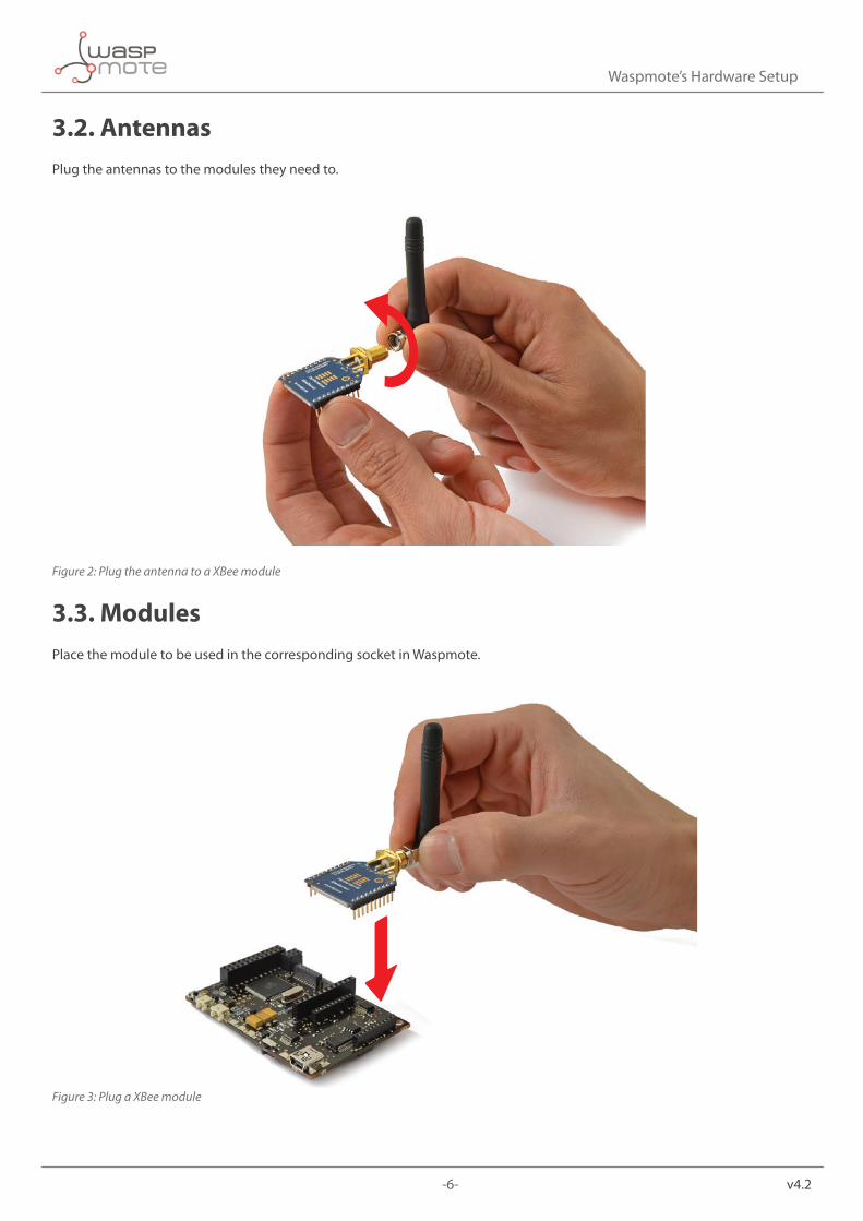
3.2. AntennasPlug the antennas to the modules they need to.
Figure 2: Plug the antenna to a XBee module
3.3. ModulesPlace the module to be used in the corresponding socket in Waspmote.
Figure 3: Plug a XBee module

-7- v4.2
Waspmote’s Hardware Setup
3.4. Sensor BoardsPlace the sensor board to be used in Waspmote.
Figure 4: Plug a Sensor Board
3.5. SD cardInsert the SD card into Waspmote.
Figure 5: Insert a SD card

-8- v4.2
Waspmote IDE: Download and Installation
4. Waspmote IDE: Download and InstallationThe first step is to install the Waspmote-IDE (Integrated Development Environment) used to program Waspmote. This IDE can be found on:
http://www.libelium.com/development/waspmote
4.1. LinuxTo be able to correctly compile and use Waspmote it is necessary to install some packets related with the version of the compiler for Atmel microcontrollers and Java environment.
a) Installing Java
The first step is to install the necessary version of the Java environment. We can use the Synaptic package manager or a terminal.
Using the Synaptic package manager, we must look for the “sun-java6-jre” package and install it.
Using the terminal we must use the apt-get command in the following way:
$ sudo apt-get install sun-java6-jre
b) Installing AVR-GCC Compiler
The next step is to install the necessary version of the avr-gcc compiler to be able to program the Waspmote ATMEGA 1281 microcontroller. We can use the Synaptic package manager or a terminal.
Using Synaptic we must look for the “gcc-avr” package and install it. Using the terminal we must use the apt-get command in the following way:
$ sudo apt-get install gcc-avr
c) Installing lib-avc Library
The next step is to install the necessary version of the lib-avc library. We can use the Synaptic package manager or a terminal.
Using Synaptic we must look for the “lib-avc” package and install it. Using the terminal we must use the apt-get command in the following way:
$ sudo apt-get install avr-libc
d) Running Waspmote IDE
Waspmote installation entails unzipping the file downloaded in the previous step to the chosen folder. Once the downloaded file has been unzipped, the file called Waspmote must be run to launch the IDE.
-9- v4.2
Waspmote IDE: Download and Installation
4.2. Windowsa) Installing Waspmote
The next step is to unzip the downloaded file to the chosen folder. This folder includes the drivers needed in the next step to install the USB and FTDI converter.
b) Connecting a Waspmote board
When connecting a Waspmote board using the mini-USB connector, the message “New device found” will appear. A window will open for the installation of this device.
Select the option “Not right now” and press the ‘Next’ button.
Next select the path where the drivers for the FTDI converter are. These drivers are in the folder where Waspmote was unzipped.
Then proceed to the installation of the FTDI converter drivers, which shows the following message when finished.
Once installation is finished, the message ‘New device found’ will appear, referring to the USB. The same process carried out for the FTDI converter must now be followed, choosing the same options in all the windows. The path for the drivers is the same as that previously specified.
Once this installation is finished, a message will appear indicating the correct installation of the USB.
Once both devices are correctly installed, the port on which the Waspmote board has been installed will appear in the “Device Administrator”.
4.3. Maca) Installing Waspmote
The next step is to unzip the downloaded file to the chosen folder. The drivers needed in the next step to install the FTDI converter are found in this folder.
b) Installing FTDI converter drivers
Waspmote requires the installation of the FTDI converter drivers. These drivers are found in the downloaded file.
Once the drivers are installed for the FTDI converter, the Waspmote board can be connected and the system will recognize it correctly.

-10- v4.2
Receiving Frames from Waspmote
5. Receiving Frames from Waspmote
5.1. In Waspmote GatewayWaspmote comes preconfigured from factory with a program which lets you check the right operation of the device. This program sends standard frames to the Gateway. It is called wasp_pro_start_program_XXX.pde and depends on the used XBee protocol. It is also available inside the IDE.
Steps:
1. Install the drivers and the serial monitor software on the computer.
2. Connect the antennas and the rest of the desired components to Waspmote and Waspmote Gateway.
3. Plug Waspmote Gateway to the USB port on the computer.
4. Launch the serial monitor application and set the next parameters:
• USB port: 115200bps • 8bits • 1 bit stop • no parity setting
5. Connect the batteries to the Waspmotes.
6. Switch Waspmotes to the ON position.
When the program starts, it executes sequentially these actions:
• State 1 – Leds ON for 5 seconds
• State 2 – Leds blinking for 3 seconds
• State 3 – Sending messages
State 1 and 2 are only executed once (when program starts) whereas state 3 will loop indefinitely every second (if we reset Waspmote, the program starts again).
Every packet contains a message with sensor data formatted as Waspmote Data Frame. The sensor fields added to the frame are: Accelerometer values, RTC internal temperature value, and battery level. In the case the XBee is not using DigiMesh protocol, then the MAC address is added (because of length constraints). For further information, please check the Waspmote Data Frame Guide in:
http://www.libelium.com/development/waspmote/documentation/programming
Example:
~\0x00I\0x90\0x00}3\0xa2\0x00@z\0xcb\0x92\0xd8\0xd3\0x02<=>\0x80\0x03#35689722##7#ACC:80;10;987#IN_TEMP:22.50#BAT:93#\0xb4
Initially there are some hexadecimal characters, which belong to the XBee API frame, followed by the message. In the above example the message is:
<=>\0x80\0x03#35689722##7#ACC:80;10;987#IN_TEMP:22.50#BAT:93#

-11- v4.2
Receiving Frames from Waspmote
5.2. In MeshliumWhen you buy a kit containing Meshlium and Waspmote, your Waspmtes already come configured to send frames to the Gateway. Later, once the user has developed the code for transmitting to Gateway, he can swich to Meshlium.
Before send frames to Meshlium, We recommend you read and study networking guides for your module:
• Waspmote 802.15.4 Networking Guide • Waspmote 868MHz Networking Guide • Waspmote 900MHz Networking Guide • Waspmote Digimesh Networking Guide • Waspmote ZigBee Networking Guide
Meshlium will receive the sensor data sent by Waspmote using the XBee radio and it will store the frames in the Local Database. That can be done in an automatic way now thanks to the new Sensor Parser.
The Sensor Parser is a new feature for Meshlium (version 3.0.5 or older). It is a new software system which is able to do the following tasks in an easy and transparent way:
• receive frames from XBee (with the Data Frame format) • parse these frames • store the data in local Database • synchronize the local Database with an external Database
Besides, the user can add his own sensors.

-12- v4.2
Compiling a New Program
6. Compiling a New ProgramTo use the Waspmote-IDE compiler we must run the executable script called ‘Waspmote’, which is in the folder where the compiler has been installed.
Waspmote is divided into 4 main parts which can be seen in the following figure.
Figure 6: IDE – Waspmote parts
• The first part is the menu which allows configuration of general parameters such as the selected serial port. • The second part is a button menu which allows verification, opening, saving or loading the selected code on the board. • The third part contains the main code which will be loaded to Waspmote. • The fourth part shows us the possible compilation and load errors, as well as the success messages if the process is
carried out satisfactorily.
The Waspmote-IDE buttons panel allows certain functions to be carried out such as opening a previously saved code, creating a new one or loading the code on the board. The following figure shows the panel and the functions of each button.
Figure 7: IDE – Waspmote panel of buttons

-13- v4.2
Compiling a New Program
Once the program has been opened correctly some configuration changes must be made so that the programs load correctly in Waspmote.
In the ‘Tools/Board’ tab the Waspmote board must be selected. This refers to the API selected.
Figure 8: Select API
In the ‘Tools/Serial Port’ tab, the USB to which Waspmote has been connected to the computer must be selected.
Figure 9: Select USB port

-14- v4.2
Compiling a New Program
Once these 2 parameters have been configured we can load a program onto Waspmote. The process will be explained using a very simple example. A series of examples for learning and familiarizing yourself with the Waspmote environment have been included in the downloaded file that contains the compiler.
The simplest example is the file called ‘test.pde’. In this example the text string “Hello World!” appears on the screen. The example shows how to load a program onto Waspmote and how to show information on the screen.
The next step is to configure the folder where the created programs are going to be saved. In the Waspmote-IDE this folder is called ‘sketchbook’ and can be configured by accessing the ‘File/Preferences’ tab. Clicking on this tab will open a new window where the location of the sketchbook can be indicated. Once the sketchbook folder path is indicated, the downloaded test program must be saved in this folder.
Waspmote-IDE must be closed so that the changes and the newly saved program in the sketchbook folder are reflected.
Run Waspmote again and open the downloaded test program by clicking on ‘Open’.
Select the ‘test.pde’ file in the path where it has been unzipped and open it. As can be seen, it is a very simple code which lights up a LED every 3 seconds and writes “Hello World!” on the screen.
The next step is to load the program onto Waspmote. To do this Waspmote must be connected to the computer through the USB and the button ‘upload’ must be clicked. Then, it will start compiling the program. When the program has been compiled correctly, a message will appear on the lower part of the window indicating this event. Conversely, if a fault occurs, red messages will appear indicating the bugs in the code. When compiling is over, the code will be loaded onto Waspmote.
When the program has been loaded correctly, a message appears in the Waspmote window indicating ‘Done Uploading’.
Conversely, if some problem occurs during loading, red messages will appear indicating the failures.
Once this program is loaded onto the board, the loaded code will run as was explained in the Architecture and System chapter.
Note: The Gateway is just a UART-USB bridge. This means that the Gateway cannot be programmed and no code can not be uploaded. Its function is to pass data from the XBee to the USB, and vice-versa.
-15- v4.2
Uploading a New Program to Waspmote
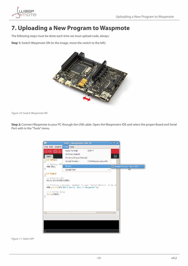
7. Uploading a New Program to WaspmoteThe following steps must be done each time we must upload code, always:
Step 1: Switch Waspmote ON (in the image, move the switch to the left).
Figure 10: Switch Waspmote ON
Step 2: Connect Waspmote to your PC through the USB cable. Open the Waspmote’s IDE and select the proper Board and Serial Port with in the “Tools” menu.
Figure 11: Select API

-16- v4.2
Uploading a New Program to Waspmote
Figure 12: Select USB port
Step 3: Prepare your code for Waspmote. In our case, go to the template of the “hello_world” or copy and paste the text in the sketch.
Step 4: Save the sketch (the IDE has a button for that), for example with the name “hello_world”, and check the IDE states “Done Saving”.
Figure 13: Save your program
-17- v4.2
Uploading a New Program to Waspmote
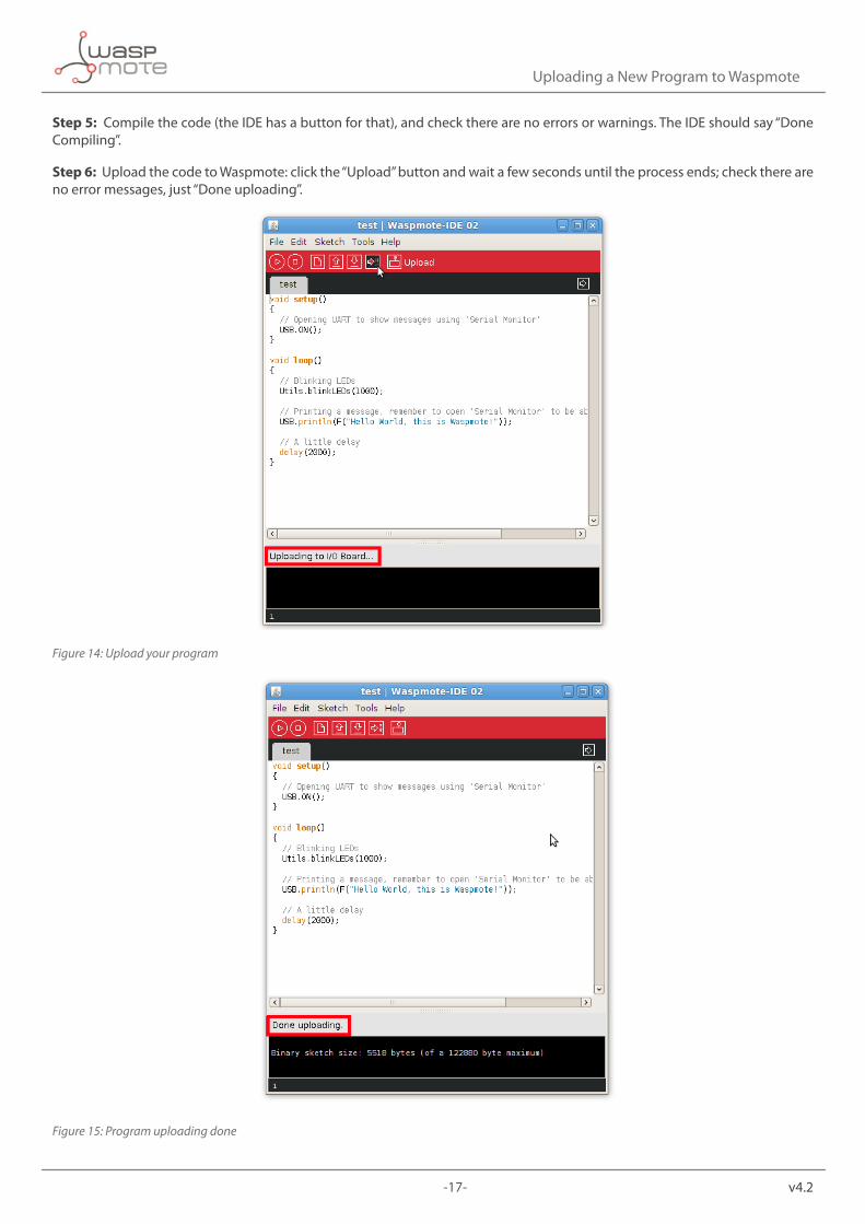
Step 5: Compile the code (the IDE has a button for that), and check there are no errors or warnings. The IDE should say “Done Compiling”.
Step 6: Upload the code to Waspmote: click the “Upload” button and wait a few seconds until the process ends; check there are no error messages, just “Done uploading”.
Figure 14: Upload your program
Figure 15: Program uploading done

-18- v4.2
How to Use the Developer’s Guides
8. How to Use the Developer’s GuidesCongratulations, if you arrived here, you completed the Quick Start Guide and now you know the basics about Waspmote.
Your next steps depend on what kind of project you want to develop. Normally, a program for Waspmote is composed of 4 parts:
1. configuration (RTC, sensors, communications module)
2. read sensor(s)
3. communications (XBee, GPRS, ...)
4. enter sleep mode
As a first step, you should read the Waspmote Technical Guide. It is a good introduction to Waspmote because it talks about all the features, modules and boards. Make sure you read the chapters about the features you need to use thoroughly.
RTC management or power/sleep features should be present in almost any type of project, so it is a good idea to start with them. Besides, they are pretty easy to control. You should read the RTC Guide and the Power Guide carefully. For any feature, module or board, there is a good number of examples, make sure you execute them in your Waspmote while you read the related guide. This will help to clear up things and you can learn concepts by doing and not just by reading. In any case, examples are arranged in increasing order of difficulty. This means you should start from the lower examples and then move to the advanced examples.
Reading sensors is also easy and it must be one of the first steps. The appropriate Sensor Guide must be read and then you can execute the related examples.
There are optional features or modules which should be studied now in the case you plan to use them: SD, accelerometer, EEPROM, etc.
We suggest to leave the communication part for the last steps, since it may be the most difficult part. Until that moment, it is a good idea to transmit your data via USB for the first steps of your development. Remember you can print as many messages as you want, so you can print helpful intermediate messages. Make sure you learn about the Frame, we advice to send frames in the official Frame format with your communication modules.
Once you arrived here, you can try to do your first complete program, combining RTC, power, sensors and communications. There are different combined examples which will show how to do it in a successful way.
Do not forget to read the Programming Guide as you advance in the project development. This Guide contains atomic tips which are useful for real-life projects. Some of the ideas shown there will help you to build successful projects.
A Gateway is always recommended. We believe it is better to start receiving frames with a Gateway, and once you feel comfortable with it, you can switch to Meshlium in the case you have one. Meshlium can be seen as an advanced Gateway. You can start by reading the Meshlium Quick Start Guide, and after that you can study the complete Meshlium Technical Guide.
If you want to use 2 communication radios, you should study them separately. First one of them; once you completed the development, continue with the 2nd one. Once you know both of them, you can try both of them in the same program. There are combined examples with 2 radios which may help.
Interruptions are one advanced feature so you can leave that for the last part of the learning process.
If you need OTA features, it is a complicated feature too and it could be a good moment now to start reading the OTA Guide and execute the examples.