technical expertise - gr electronicsgrelectronics.co.in/allproducts.pdf · technical expertise ......
TRANSCRIPT

Technical Expertise
Tradition of Excellence:
GR has been a pioneer and innovator of special type magnetic products since 1997. We enjoy a rich tradition of meeting the
highest industry standards for quality, durability and reliability in industrial markets.
We continue that tradition to-day in the contractors, industrial and OEM markets with a variety of new magnetic products.
GR Electronics has necessary design
experience over 30 years for the following
products to meet the demanding needs of To-days Power Industry. We are committed to manufacturing a technically superior product
with quality that will not be scarified for commercial advantage.
Line / Load Reactors for VFDs
Reactors are the modern technology
solution for drive application. The reactors help to keep the drive running longer by
absorbing many of the power line disturbances which may cause damage or shut down the drive. Line Reactors are
economical, versatile power quality solutions for VFD drives
• Our manufacturing capacity range is 2A to 2000A.
DC Link Choke:
When added between input rectifier and bus capacitor the link choke will improve the DC bus and AC input waveforms. In this
location the DC choke will reduce the amount of AC ripple on the DC bus, reduce the AC input harmonics and offer protection against
nuisance tripping due to spikes such as those caused by capacitor switching.
• Our manufacturing capacity range
is 2A to 2000A.
Current Transformers:
GR Current Transformers are
manufactured to meet accuracy levels to meet IS-2705.
Every CT is tested in accordance with IS-2705 for ratio accuracy and phase angle errors with microprocessor based automatic instrument
transformer test set with facilities for an automatic print out of test results.
Our manufacturing capacity range is 30A to 3500A for Metering class & protection class CTs. We are also manufacturing
special types CTs like Class Ps(X), Interposing, Summation, Bushing type, Core balance, and precision grade current
transformers as per customer requirements.
Braking Resistors for VFDs:
Ac variable frequency drives are commonly used with a general purpose AC induction motor to form a reliable variable
speed drive system. For applications that require faster deceleration rates, a braking resistor is required.
• Our manufacturing capacity range is 0.3KW to 200KW
Industrial control transformers:
GR Industrial control transformers are designed to meet IS-12021 especially for
maintaining a high degree of regulation even at eight time’s normal load. This
feature is essentially required for industrial control application.
• Our manufacturing Capacity range
is 100VA to 3500VA.
Dry Type Transformers:
Advantage of dry type power transformers include compact size, light weight, durability, and low cost. While dry
type transformers are not designed to handle the heat capacity and momentary overloads of liquid-filled units, these transformers are still
suitable for a wide range of application.
• Our manufacturing Capacity range
is 1KVA to 100KVA.
K-Rated Transformers:
K-Rated Transformers designed
specially for use on systems that generate
high levels of harmonic currents. The line is available in most common ratings of K-4, K-13 and K-20. K- Factor rating indicates the
transformers ability to tolerate the additional heating caused by harmonics.
Harmonics increases heating losses in transformer. Sources of these losses are deep within windings and source close are closure
to surface. Oil filled transformers react differently to the increased heat and are better able to cool them selves. Dry type
transformers are more susceptible to the harmonic currents and are so labeled.
GR incorporates special winding
techniques to minimize eddy current losses
caused by harmonic loads. A double sized neutral conductor is used handle excessive neutral currents and a faraday shield helps
eliminate line noise voltage spikes. • Our manufacturing Capacity range
is 10KVA to 100KVA.
De-Tuned Reactors:
Tuning reactors are designed to be
used in conjunction with power factor
capacitors whenever non-linear loads are presents. Since all distribution systems contain some amount parasitic inductance, in
addition of power factor capacitors creates a parallel resonate tank circuit.
The frequency of resonance is a function of the amount of the inductance in that systems. When non-linear loads are
presents the harmonic frequencies generated by these loads may force the tank circuit into uncontrolled resonance. This can cause failure
of either capacitor of the capacitor themselves, or both.
• Our manufacturing Capacity range is 1KVAR to 100KVAR
In-rush Current limiting Reactor:
When a capacitor bank is energized,
the bank and the network are subjected to transient’s voltage and current. The severity of the effect is determined by the size of the
capacitor and the network impendence. Large and high frequency inrush current can damage capacitors, circuit breakers and
contactors. All connected equipments are subject to voltage transients and may result in sporadic malfunction or failure.
To avoid this problem, it is common
practice to insert inrush limiting reactors in
series with the capacitors. • Our manufacturing Capacity range
is 1KVAR to 100KVAR
Harmonic Filters:
VFD and other types of non-linear loads
take the incoming power from the utility and modify it more efficient use within a wide range of applications. Since this conversion
process is not using the power efficiently as it is supplied by utility, distortion of both current waveform and voltage wave form occurs.
This distortion is set of frequencies that
combine with the fundamental to create a new
waveform. If non-linear loads represent a significant portion of the entire load, this distortion begins to cause problems
throughout the electrical systems. These problems range from transformer equipment over heating to random breaker tripping.
Harmonics may even cause sensitive equipments to fail completely. Another by-product of this distortion is poor power factor.
Sizing harmonic filters are applied in
increments of KVAR. VFD drive will require
30% of horse power in KVAR an SCR drive will require 40% of its rated horse power in KVAR.
GR Electronics No: 417 C.T.H. Road, Ambattur, Chennai 600 053.
Ph: 91 9444204873 / 044-26574529/ 26574945 E-mail : [email protected]

GLR Series Line / Load Reactors
Applications:
GLR series three phase AC reactors are intended for use as input filters or output
filters for AC-PWM variable frequency drives. Drive performance is significantly improved, the drives input rectifier is protected from
failure or damage, and drive harmonic demands are tamed with the addition of a K-rated reactor. GLR reactors act as interface
buffers between solid state power circuits and the line or the motor. All drives, in any application, will benefit when applied with GLR
series reactor.
VFD Without Reactor:
Drives are susceptible to problems caused at their interface to the line or motor. Some of these issues include AC voltage
waveform line notching or cross-talk, DC bus over voltage trips, inverter over current and over voltage, and poor total power factor.
Since all drives demand nonlinear current and voltage, drives demand currents rich in harmonics.
VFD With GLR Reactor:
GLR reactors provide additional circuit
inductance which slows rapid changes in current that are the heart of the problems
listed above. 1. Voltage line notching, or commutation
notching, is caused by SCR phase-controlled rectifiers. GLR reactors provide a voltage-dividing impedance which reduces the depth
and rounds the edges of the notches, thereby eliminating drive cross-talk, interference, and equipment damage.
2. Transient voltages (See Figure) on the AC
power lines can cause inrush currents to an AC-PWM drive, resulting in an over voltage condition of the DC bus. These transient
voltage conditions are often caused by utility capacitor
switching and will cause VFDs to shut down
without warning. The addition of a GLR reactor will limit the magnitude of inrush current, preventing trips and component failures. (See
Figure above )
3.) When used as output filters, GLR reactors prevent inverter instantaneous over current
trips because they provide needed inductance when the load on an inverter has an abnormally high capacitance. For example, if a
single inverter is powering multiple motors, the load may look capacitive, causing inverter shutdown.
4.) The addition of a GLR reactor limits inrush current to the rectifier, rounding the waveform, reducing peak currents, and
lowering harmonic current distortion. High peak currents may cause “flat topping” of the voltage waveform. Reducing those peak
currents also reduces total harmonic voltage distortion. (See Figure above.)
5.) The addition of a GLR reactor reduces total RMS current without affecting the work being done. Therefore, total power factor is
improved.
The Line Reactors are required for the
following cases at the input:
• Power supply with high frequency transients such as voltage surges, line
notching, pulsed distortion and harmonics
• Drive supplied by a low impedance line. If the KVA rating of the the Ac supply transformer is greater than ten times the input KVA rating of the drive, a 5%
input line reactor must be added. • Power supply with phase un balance greater than 2% of the voltage. An
unbalance greater than 25 can shorten the life of drive and results in severe damage to drive power components.
• Installation having more than two drives installed on the same power line. Multiple drives on a common power line
require one reactor per drive to reduce cross talk.
When Line Reactors are used at the
Output:
The reactors help to protect motors from high peak voltage and fast rise times (dv/dt) which can be experienced in IGBT
application when there is long cable length between the drive and the motor. High voltage can be experienced at the motor
terminals especially when distance between drive and motor is more than 10 meters. This typically caused by the voltage doubling
phenomenon of a transmission line having unequal line and load impedances. Motor terminal voltage can reach twice DC bus
voltage (1600V) in long lead application. The reactor contain appropriate value of inductance which removes the steep edges
from PWM voltage wave form, sparing motors from brutal voltage spiking and also helps to:
• To reduce motor temperature and motor audible noise.
• To protect the drive from surge current caused by rapid change in load.
Recommended impedance levels:
A 2.4% to 3% eliminates bus over
voltage tripping. 5 to 6% protects against physical damage to most drive components and offers harmonic reduction without added
capacitance. 1.5% is the recommended input minimum to protect the drive and is the
recommended maximum impedance when the filter is used as an output device.
Design Features
Distributed Air Gap Technology
As reactors and their required air-
gaps gets bigger, flux fringing and eddy currents can cause heating and insulation breakdown. GR has addressed this issue in
larger. GLR reactors by utilizing Distributed Gap technology - a construction technique that subdivides a large gap into two or more
smaller gaps. A GLR reactor built with this technique will run cooler and last longer than the competitions cheaper single gap products.
Low Loss:
The harmonic currents generated by AC drive increase eddy current losses (Heat) in reactor windings. The thicker the winding
conductor, the greater the losses. GR uses thin strip conductors which provide lower eddy
losses than comparable thick conductor wound units. Lower losses = Cooler operation and longer reactor life.
Harmonic Attenuation:
Our unique harmonic compensation assures maximum circuit inductance in the presence of complex waveforms and can be
relied upon to minimize input total harmonic current distortion (THID). Additionally it offers superior absorption of transient voltage
spikes. Our standard reactors will typically reduce 6-pulse rectifier input current harmonics to the following levels at full load
operating conditions: • 3% reactor alone 45% or less THID • 5% reactor alone 35% or less THID • 3% AC reactor + 3% DC link choke 33% or less THID
• 5% AC reactor + 3% DC link choke 28% or less THID
Over Load (Service Factor):
GR reactors are compensated for the additional currents and high frequencies
caused by the presence of harmonics. The reactor fundamental current rating indicates the typical full load motor current and is also
the basis of impedance rating. GR reactors offer a full 1.5 service factor rating which allows them to carry over load current up to
150% of their fundamental rating when applied as an input line reactor.
Since the name plate ratings of motor drives (VFD) varies widely by manufacturer, this
helps to assure that the reactor maximum current rating is compatible with the name plate current rating of the VFD. The service
factor rating compensates for VFD manufacturer variances in motor drive current ratings and for harmonic currents. Nominal
inductance is assured all the way up to the service factor current rating.
Audible Noise:
GR Line/Load reactors offer low noise
operation. Core and coil construction, flux density control, harmonic compensation assures minimal audible noise radiation.
Although our reactors are typically quiet, waveforms vary by drive type and application
and therefore reactor audible noise may vary by the application.
PWM/IGBT Protection:
GR Reactors are specially designed and
constructed for IGBT protection for drive application. A premium dielectric system is utilized to have a 3000V rms insulation
dielectric strength required for IGBT application. GR Reactors are featured “triple insulation” suitable IGBT drives with switching
frequency up to 20Khz.
K-Rated:
A standard reactor is not designed for high harmonic currents and it will over heat
and fail prematurely when connected to drive loads. For this reason a special reactor has been designed. This reactor is K-Rated
reactor. This reactors are designed to have higher magnetic to resistive properties to handle heat generated harmonic currents.
High Reactor Linearity:
The linearity of GR Reactors is to offer 100% of their nominal inductance even at 150% of their current rating. This assures
maximum filtering of distortion even in the presence of severe harmonics and absorption
of surges.
Reactor Installation:
GR Reactors are available in open construction and with enclosure. Open
Reactors are designed for mounting within appropriate electrical equipment enclosure. Reactors rated 80A and under are designed
for mounting in both vertical and horizontal position. Larger reactors must be mounted in horizontal position typically on the floor of the
enclosure. Allow side clearances of 100mm and vertical clearances of 150mm for proper heat
dissipation and access. The part of the enclosure containing Line Reactors must be forced ventilated according
the dissipated power. Minimum Air flow must be: F= 0.3 X Ps in (Ps = power
dissipated by the Line reactor)
Limited Warranty:
• GR Electronics warrants to the original purchaser only that the reactors will be
free from defects in material and workmanship for period of two years from the date of shipment.
• Our liability is limited only to the repair or replacement of product defective in materials or workmanships. GR shall not in
any event, be liable for incidental damages or consequential damage or economic loss.
• This warranty shall not apply to the defects that occur to improper storage / handling or misuse.
Tests conducted at our works
• Visual inspection for general workmanship, Quality and finish.
• Measurement of impedance value @ rated Fundamental current.
• Measurement of Insulation resistance with Insulation tester.
• High Voltage test at 3KV for one minute between live parts to earth
GR Electronics No: 417 C.T.H. Road, Ambattur, Chennai 600 053.
Ph: 91 9444204873 / 044-26574529/ 26574945 E-mail : [email protected]

Technical Data For 3% Impedance Rating - Three Phase Line Reactor Model
No.
Capacity
HP/KW
Moto
Curr.
Fund.
Curr.
Max
Curr.
Mh.
Value
Watt
Loss
Ter.
Arr.
Wt.
Kg
Size
W H D
GLR03-002 1.0/0.75 2.1A 2A 3A 12.0 10W TB 3.0 180 145 85
GLR03-004 2.0/1.5 3.4A 4A 6A 6.0 15W TB 3.5 180 145 95
GLR03-006 3.0/2.2 4.8A 6A 9A 4.0 25W TB 4.0 180 145 100
GLR03-008 5.0/3.7 7.6A 8A 12A 3.0 30W TB 4.5 180 145 100
GLR03-012 7.5/5.5 11A 12A 18A 2.0 40W TB 5.5 180 190 100
GLR03-016 10/7.5 14A 16A 24A 1.5 55W TB 6.0 180 190 105
GLR03-025 15/11 21A 25A 38A 1.0 80W TB 11 270 245 140
GLR03-030 20/15 27A 30A 45A 0.80 80W TB 12 270 245 140
GLR03-035 25/18.5 34A 35A 53A 0.70 90W TB 13 270 245 140
GLR03-040 30/22 40A 40A 60A 0.60 90W TB 14 270 245 155
GLR03-055 40/30 52A 55A 83A 0.45 110W TB 15 270 245 155
GLR03-070 50/37 65A 70A 105A 0.35 150W TB 16 270 245 170
GLR03-080 60/45 77A 80A 120A 0.30 170W TB 17 270 245 170
GLR03-100 75/55 96A 100A 150A 0.25 180W LUG 25 330 270 180
GLR03-130 100/75 124A 130A 195A 0.18 200W LUG 28 330 270 190
GLR03-160 125/93 156A 160A 240A 0.15 220W LUG 30 330 270 190
GLR03-200 150/110 180A 200A 300A 0.12 240W LUG 43 330 340 230
GLR03-250 200/150 240A 250A 375A 0.095 260W LUG 45 330 340 230
GLR03-300 250/186 302A 300A 450A 0.08 300W LUG 48 330 340 240
GLR03-375 300/225 361A 375A 563A 0.065 330W LUG 63 330 340 310
GLR03-425 350/260 414A 425A 638A 0.055 350W LUG 65 330 340 310
GLR03-480 400/298 477A 480A 720A 0.050 375W LUG 70 330 340 320
GLR03-525 450/335 515A 525A 788A 0.045 400W LUG 75 330 340 330
GLR03-600 500/372 590A 600A 900A 0.040 425W LUG 80 330 380 350
GLR03-750 600/447 720A 750A 950A 0.035 450W LUG 85 330 380 350
Technical Data For 5% Impedance Rating - Single Phase Line Reactor GLR103-02 .25/0.18 2A 2A 3A 19.0 10W TB 2 95 110 65
GLR103-04 0.5/0.37 4A 4A 6A 9.5 12W TB 2.5 95 110 65
GLR103-06 1.0/0.75 6A 6A 9A 6.5 15W TB 4 95 150 90
GLR103-08 1.5/1.1 8A 8A 12A 4.8 20W TB 4 95 150 90
GLR103-10 2.0/1.5 10A 10A 15A 3.8 25W TB 4.5 95 150 100
GLR103-12 3.0/2.2 12A 12A 18A 3.2 30W TB 5 95 150 100

Current Transformers
Application:
GR Current Transformers are manufactured to
meet indoor or internal equipments for Switch gear, Distribution Systems, Generator Sets and control panels. Current Transformers are
custom-built product supplied in Ring/Rectangular type in a wide range of ratios and accuracies. CTS have single, dual or
multi-ratio windings are capable of accuracy levels to meet IS-2705.
Fabrication:
The accuracy of CT is a function of the magnetic performance of the steel core. Toridally wound cores with high permeability
and low loss are used to optimize performance and physical size of the transformers. High grade insulation is used to insulate between
the windings and the core and between winding layers. Maximum mechanical and electrical performance is achieved by
distributing all windings evenly around the periphery of core. The exterior of the transformer is finished with ABS cover which
provides an excellent external mechanical protective body & look and long term dielectric performance.
Accuracy Class:
In the case of metering CT s, accuracy class is typically, 0.2, 0.5, 1 or 3. This means that the errors have to be within the limits specified in
the standards for that particular accuracy class. The metering CT has to be accurate from 5% to 120% of the rated primary
current, at 25% and 100% of the rated burden at the specified power factor. In the case of protection CT s, the CT s should pass
both the ratio and phase errors at the specified accuracy class, usually 5P or 10P, as well as composite error at the accuracy limit
factor of the CT.
Composite Error:
The rms value of the difference between the instantaneous primary current and the
instantaneous secondary current multiplied by the turns ratio, under steady state conditions.
Accuracy Limit Factor:
The value of primary current up to which the
CT complies with composite error requirements. This is typically 5, 10 or 15, which means that the composite error of the
CT has to be within specified limits at 5, 10 or 15 times the rated primary current.
Composite Error:
The rms value of the difference between the
instantaneous primary current and the instantaneous secondary current multiplied by the turns ratio, under steady state conditions.
The following factors affect CT prices:
Specifying a higher VA or CLASS than necessary usually results in a higher cost. The
cost generally increases as the CT internal diameter increases. 1A CTS are usually more expensive than 5A.
Instruments security factor:
To protect the instruments and meters from being damaged by high currents during fault conditions, a metering core must be saturated typically between 5 and 20 times the rated currents. The rated Instrument Security Factor (FS) indicates the over current as a multiple of the rated current at which the metering core will saturate. It is thus limiting the secondary current to FS times the rated current. ISF for GR meter CTS are deigned to less than 5. The safety of the metering equipment is greatest when GR CTS are used.
Testing:
Every CT is tested in accordance with IS-2705 for ratio accuracy and phase angle errors with microprocessor based automatic instrument
transformer test set with facilities for an automatic print out of test results. Test
comparisons are made with standard traceable NPL to validate ratio accuracy performance for all CTS. For protection class CT the
performance is verified by excitation measurements.
Metering Class CTS:
In general the following applies: Accuracy Class Requirements:
• 0.1or 0.2 for precision measurements. • 0.5 for high grade kilowatt hour meters. • 1.0 for commercial grade kilowatt hour
meters • 1 or 3 for general industrial
measurements.
• 3 or 5 for approximate measurements Burden Requirements: • Ammeter : 1VA
• Current coil of Watt/Var meter : 1.5 VA • Current coil of energy meter : 2.0 VA
• Current coil of p.f. indicator : 2.5 VA • Current coil of Trivector meter : 3.0 VA • Leads between CT & meter : 2.0 VA
Protection Class CTS:
In addition to general specification required for CT design, protection CTS require an Accuracy Limit Factor (ALF). This is the
multiple of rated current up to which the CT will operate while complying with the accuracy class requirements. In general the following
applies: • Instantaneous over current relays &
trip coils – 2.5VA class 10P5
• Thermal inverse time relays :7.5VA Class 10P10
• Low consumption Relay : 2.5VA class
10P10 • Inverse definite min. time relays(IDMT)
Over current: 15VA Class 10P10/15
• IDMT earth fault relays with fault stability or accurate time grading required : 15VA 5P10
Special Type Current Transformers
Class PS(X) CTS:
Class PS CTs are special CTs used mainly in
balanced protection systems (including restricted earth fault) where the system is sensitively dependent on CT accuracy. Further
to the general CT specifications, we now need to know:
• Vkp- Voltage knee point • Io – Maximum magnetizing current at
Vkp
• Rs – Maximum resistance of the secondary winding.
Knee Point Voltage:
That point on the magnetizing curve where an
increase of 10% in the flux density (voltage) causes an increase of 50% in the magnetizing force (current).
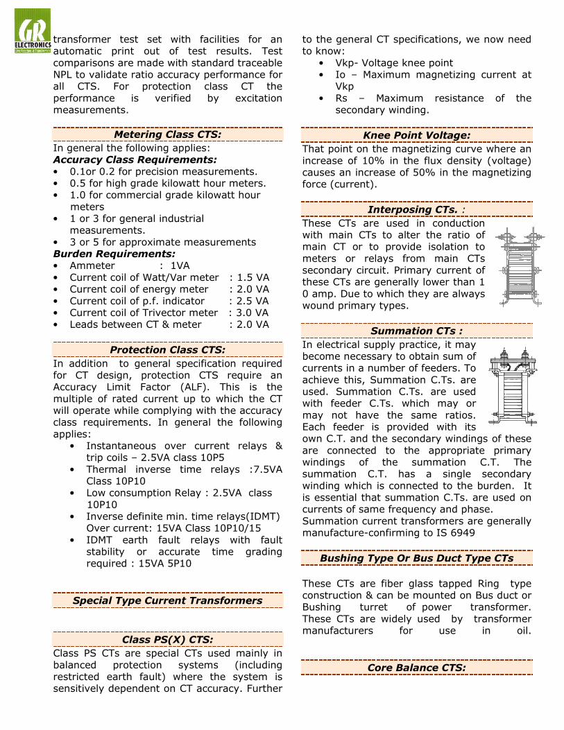
Interposing CTs. :
These CTs are used in conduction with main CTs to alter the ratio of main CT or to provide isolation to
meters or relays from main CTs secondary circuit. Primary current of these CTs are generally lower than 1
0 amp. Due to which they are always wound primary types.
Summation CTs :
In electrical supply practice, it may become necessary to obtain sum of currents in a number of feeders. To
achieve this, Summation C.Ts. are used. Summation C.Ts. are used with feeder C.Ts. which may or
may not have the same ratios. Each feeder is provided with its own C.T. and the secondary windings of these
are connected to the appropriate primary windings of the summation C.T. The summation C.T. has a single secondary
winding which is connected to the burden. It is essential that summation C.Ts. are used on currents of same frequency and phase.
Summation current transformers are generally manufacture-confirming to IS 6949
Bushing Type Or Bus Duct Type CTs
These CTs are fiber glass tapped Ring type construction & can be mounted on Bus duct or Bushing turret of power transformer.
These CTs are widely used by transformer manufacturers for use in oil.
Core Balance CTS:

Core Balance Current Transformers are used with suitable relays for the earth leakage protection purposes. C.B.C.T. encircles a 3
Phase, 3 core cable or 3 single core cables. During healthy conditions i.e. when there is no earth leakage current, the secondary of
C.B.C.T. does not carry, any current as there is no magnetic flux in the core. In the event of occurrence of earth leakage an unbalance
current sets up flux in the core of the C.B.C.T. and current flows through the secondary winding, causing the relay to operate.
Precision Grade Current Transformer:
These CTs are of accuracy of 0.1, 0.2 or 0.5
and used as a standard current transformer to check accuracies of other transformer. These current transformers are either wound primary
or ring type and manufactured in teakwood cases.
GR Electronics No: 417 C.T.H. Road, Ambattur, Chennai 600 053.
Ph: 91 9444204873 / 044-26574529/ 26574945 E-mail: [email protected]
Metering Class Ring Type CTs Data Dimension Ring
Size OD ID HT
Ratio
Burd.
VA
Acc.
Class
I 80 25 40 30/5 3 3
I 80 25 40 40/5 3 3
I 80 25 40 50/5 3 1
I 80 25 40 60/5 5 1
I 80 25 40 80/5 5 1
I 80 25 40 100/5 5 1
I 80 25 40 150/5 5 1
II 90 45 40 200/5 10 1
II 90 45 40 250/5 15 1
II 90 45 40 300/5 15 1
II 90 45 40 400/5 15 1
III 100 55 40 400/5 15 1
III 100 55 40 500/5 15 1
III 100 55 40 600/5 15 1
III 100 55 40 800/5 15 1
IV 120 70 30 800/5 15 1
IV 120 70 30 1000/5 15 1
IV 120 70 30 1200/5 15 1
IV 120 70 30 1600/5 15 1
V 135 85 30 1200/5 15 1
V 135 85 30 1600/5 15 1
V 135 85 30 2000/5 15 1
VI 165 115 35 2500/5 15 1
VI 165 115 35 3000/5 15 1
VI 165 115 35 3500/5 15 1
Protection Class Ring Type CTs Data Dimension Ring
Size OD ID HT
Ratio
Burd.
VA
Acc.
Class
I 80 25 70 100/5 5 10P5
I 80 25 125 100/5 10 10P5
I 80 25 70 150/5 7.5 10P5
I 80 25 125 150/5 7.5 10P5
I 80 25 70 200/5 10 10P5
I 80 25 125 200/5 10 10P10
II 90 45 70 200/5 10 10P5
II 90 45 125 200/5 10 10P10
II 90 45 125 300/5 15 10P10
II 90 45 125 400/5 15 10P10
III 100 55 125 400/5 15 10P10
III 100 55 110 500/5 15 10P10
III 100 55 90 600/5 15 10P10
IV 120 70 80 600/5 15 5P/10P10
IV 120 70 60 800/5 15 5P/10P10
IV 120 70 60 1000/5 15 5P/10P10
IV 120 70 60 1200/5 15 5P/10P10
V 135 85 60 1000/5 15 5P/10P10
V 135 85 60 1200/5 15 5P/10P10
V 135 85 60 1600/5 15 5P/10P10
V 135 85 50 2000/5 15 5P/10P10
VI 165 115 60 1600/5 15 5P/10P10
VI 165 115 50 2000/5 15 5P/10P10
VI 165 115 50 2500/5 15 5P/10P10
VI 165 115 50 3000/5 15 5P/10P10
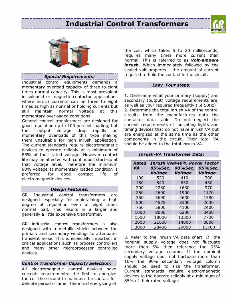
Industrial Control Transformers
Special Requirements:
Industrial control equipments demands a
momentary overload capacity of three to eight times normal capacity. This is most prevalent in solenoid or magnetic contactor applications
where inrush currents can be three to eight times as high as normal or holding currents but still maintain normal voltage at this
momentary overloaded conditions. General control transformers are designed for good regulation up to 100 percent loading, but
their output voltage drop rapidly on momentary overloads of this type making them unsuitable for high inrush application.
The current standards require electromagnetic devices to operate reliably at a minimum of 85% of their rated voltage. However contact
life may be affected with continuous start-up at that voltage level. Therefore the minimum
90% voltage at momentary loaded condition is preferred for good contact life of electromagnetic devices.
Design Features:
GR Industrial control transformers are designed especially for maintaining a high degree of regulation even at eight times
normal load. This results in a larger and generally a little expensive transformer.
GR industrial control transformers is also designed with a metallic shield between the primary and secondary windings to attenuates
transient noise. This is especially important in critical applications such as process controllers and many other microprocessor controlled
devices.
Control Transformer Capacity Selection:
All electromagnetic control devices have currents requirements: the first to energize
the coil the second to maintain the contact for definite period of time. The initial energizing of
the coil, which takes 5 to 20 milliseconds, requires many times more current than normal. This is referred to as Volt-ampere
inrush. Which immediately followed by the sealed volt amperes – the amount of current required to hold the contact in the circuit.
Easy, Four steps:
1. Determine what your primary (supply) and secondary (output) voltage requirements are,
as well as your required frequently (i.e 50Hz) 2. Determine the total inrush VA of the control circuits from the manufactures data the
contactor data table. Do not neglect the current requirements of indicating lights and timing devices that do not have inrush VA but
are energized at the same time as the other components in the circuit. Their total VA should be added to the total inrush VA.
Inrush-VA Transformer Data:
3. Refer to the inrush VA data chart. If the
nominal supply voltage does not fluctuate more then 5% then reference the 95% secondary voltage column. If the nominal
supply voltage does not fluctuate more than 10% the 90% secondary voltage column should be used to size the transformer.
Current standards require electromagnetic devices to the operate reliably at a minimum of 85% of their rated voltage.
Inrush VA@40% Power Factor Rated VA 85%Sec.
Voltage
90%Sec.
Voltage
95%Sec.
Voltage
100 520 410 300
150 840 630 430
200 2280 1630 970
250 2600 1900 1170
350 3690 2630 1580
500 4575 3300 2030
750 5800 4100 2400
1000 9000 6200 3400
1500 18800 13300 7700
2000 21600 14800 8000
3000 28400 20000 11700

However contact life may be affected with continuous start-up at that voltage level.
Therefore, the minimum 85% secondary voltage column should only be used as reference. Go down the column you have
selected until you arrive at the inrush VA does not to, but not less than, the inrush VA of your control circuit.
4. Read to the far left side of the chart below and you have selected the continuous normal VA rating of the transformer needed. The total
sealed VA of the control circuit must not exceed the normal VA rating of the transformer selected from the manufacturer’s data or the
contactors data table.
Features:
Voltage regulation of GR control transformer exceeds standard requirements. Secondary
voltage drops between no-load and momentary overload remains exceptionally low.
This excellent secondary circuit voltage regulation assures reliable operation of electromagnetic components and may permit
the usage of a smaller and less expensive industrial control transformer.
• Constructed with high quality silicon
steel lamination to minimize core loses and increase efficiency.
• Design incorporate precision wound coils
for improved regulation. • 130 degree insulation class, 70 degree
temperature rise.
Tests conducted at our works
• Visual inspection for general
workmanship, Quality and finish.
• No-Load Test at rated input Voltage • Short- Circuit test at rated current • Measurement of Insulation resistance
with Insulation tester. • High Voltage test at 2KV for one
minute between live parts to earth
Dimensional details:
Limited Warranty:
• GR Electronics warrants to the original purchaser only that the reactors will be free from defects in material and
workmanship for period of one year from the date of shipment.
• Our liability is limited only to the repair or replacement of product defective in materials or workmanships. GR shall not in
any event, be liable for incidental damages or consequential damage or economic loss.
• This warranty shall not apply to the defects
that occur to improper storage / handling or misuse.
Winding Configuration:
Standard Voltage Ratios:
Primary: 0-380-400-415-440V
Secondary: 0-110-115V or 0-220-230V (or) Primary: 0-220-230-240V
Secondary: 0-110-115V
Cap.
VA
W
mm
D
mm
H
mm
Wt.
kgs
100 115 120 135 3.8
150 115 130 135 4.5
250 155 125 165 6
350 155 140 165 7
500 155 155 165 10
750 185 155 250 14
1000 185 165 250 15
1500 240 175 270 21
2000 240 185 270 29
3000 240 240 300 42
3500 240 250 320 45
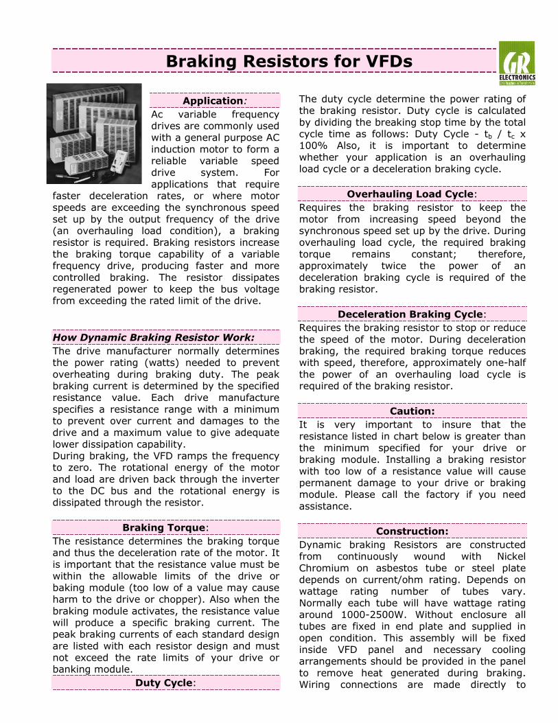
Braking Resistors for VFDs
Application:
Ac variable frequency drives are commonly used with a general purpose AC
induction motor to form a reliable variable speed drive system. For
applications that require faster deceleration rates, or where motor speeds are exceeding the synchronous speed
set up by the output frequency of the drive (an overhauling load condition), a braking resistor is required. Braking resistors increase
the braking torque capability of a variable frequency drive, producing faster and more
controlled braking. The resistor dissipates regenerated power to keep the bus voltage from exceeding the rated limit of the drive.
How Dynamic Braking Resistor Work:
The drive manufacturer normally determines the power rating (watts) needed to prevent
overheating during braking duty. The peak braking current is determined by the specified resistance value. Each drive manufacture
specifies a resistance range with a minimum to prevent over current and damages to the drive and a maximum value to give adequate
lower dissipation capability. During braking, the VFD ramps the frequency to zero. The rotational energy of the motor
and load are driven back through the inverter to the DC bus and the rotational energy is dissipated through the resistor.
Braking Torque:
The resistance determines the braking torque and thus the deceleration rate of the motor. It is important that the resistance value must be
within the allowable limits of the drive or baking module (too low of a value may cause harm to the drive or chopper). Also when the
braking module activates, the resistance value will produce a specific braking current. The peak braking currents of each standard design
are listed with each resistor design and must not exceed the rate limits of your drive or banking module.
Duty Cycle:
The duty cycle determine the power rating of the braking resistor. Duty cycle is calculated
by dividing the breaking stop time by the total cycle time as follows: Duty Cycle - tb / tc x 100% Also, it is important to determine
whether your application is an overhauling load cycle or a deceleration braking cycle.
Overhauling Load Cycle:
Requires the braking resistor to keep the
motor from increasing speed beyond the synchronous speed set up by the drive. During overhauling load cycle, the required braking
torque remains constant; therefore, approximately twice the power of an
deceleration braking cycle is required of the braking resistor.
Deceleration Braking Cycle:
Requires the braking resistor to stop or reduce
the speed of the motor. During deceleration braking, the required braking torque reduces with speed, therefore, approximately one-half
the power of an overhauling load cycle is required of the braking resistor.
Caution:
It is very important to insure that the
resistance listed in chart below is greater than the minimum specified for your drive or braking module. Installing a braking resistor
with too low of a resistance value will cause permanent damage to your drive or braking module. Please call the factory if you need
assistance.
Construction:
Dynamic braking Resistors are constructed from continuously wound with Nickel
Chromium on asbestos tube or steel plate depends on current/ohm rating. Depends on wattage rating number of tubes vary.
Normally each tube will have wattage rating around 1000-2500W. Without enclosure all tubes are fixed in end plate and supplied in
open condition. This assembly will be fixed inside VFD panel and necessary cooling arrangements should be provided in the panel
to remove heat generated during braking. Wiring connections are made directly to
resistor terminals. The wire should be high temperature grade since the resistor element
may go up to 350 degrees during braking.
Temperature Rise Limits:
Unless, otherwise specifically confirmed by us, all the resistors are designed for Temperature
Rise up to 375 deg. C. over ambient temperature, except Dynamic Breaking Resistors. Further resistors can also be
designed as per customer’s requirement & specifications for different temperature Rise limits and for that matter any limit can be
achieved. Dynamic Breaking Resistors are designed for maximum Temperature Rise of 760 deg. C as per IEEE 32
Braking Resistor Installation:
Braking Resistors are available in open construction and with enclosure. Open Resistors are designed for mounting within
appropriate electrical equipment enclosure. Resistor rated 5KW and under are
recommended for mounting inside switch gear cubicle. The DBR should be mounted in the upper part of the cubicle to avoid over
heating the installed switch gears. Allow side clearances of 100mm and vertical clearances of 150mm for proper heat
dissipation and access.
The part of the enclosure containing Braking
resistors must be forced ventilated according the dissipated power. Minimum Air flow must be: F= 0.04 X Ps in (Ps = power
dissipated by the Braking Resistor)
Limited Warranty:
• GR Electronics warrants to the original purchaser only that the reactors will be
free from defects in material and workmanship for period of one year from the date of shipment.
• Our liability is limited only to the repair or replacement of product defective in materials or workmanships. GR shall not in
any event, be liable for incidental damages or consequential damage or economic loss.
• This warranty shall not apply to the defects
that occur to improper storage, handling or misuse.
Tests conducted at our works
• Visual inspection for general workmanship, Quality and finish.
• Measurement Resistance Value
• Measurement of Insulation resistance with Insulation tester.
• High Voltage test at 2KV for one
minute between live parts to earth
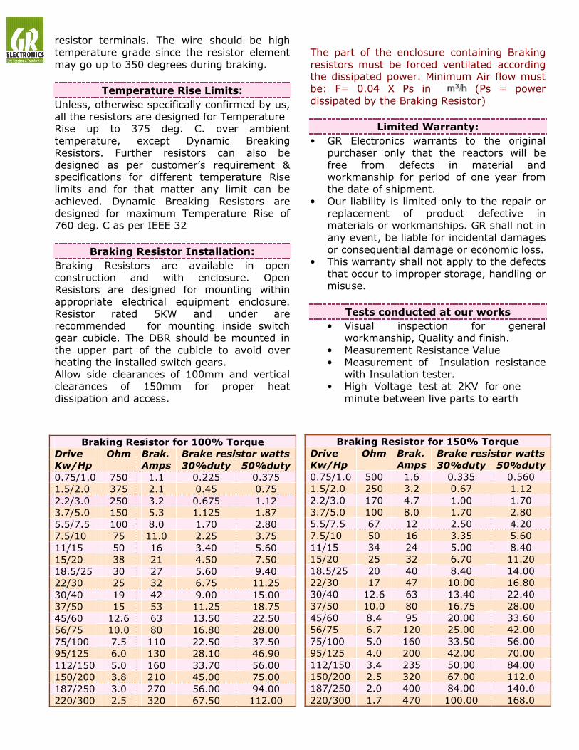
Braking Resistor for 100% Torque
Brake resistor watts Drive
Kw/Hp
Ohm
Brak.
Amps 30%duty 50%duty
0.75/1.0 750 1.1 0.225 0.375
1.5/2.0 375 2.1 0.45 0.75
2.2/3.0 250 3.2 0.675 1.12
3.7/5.0 150 5.3 1.125 1.87
5.5/7.5 100 8.0 1.70 2.80
7.5/10 75 11.0 2.25 3.75
11/15 50 16 3.40 5.60
15/20 38 21 4.50 7.50
18.5/25 30 27 5.60 9.40
22/30 25 32 6.75 11.25
30/40 19 42 9.00 15.00
37/50 15 53 11.25 18.75
45/60 12.6 63 13.50 22.50
56/75 10.0 80 16.80 28.00
75/100 7.5 110 22.50 37.50
95/125 6.0 130 28.10 46.90
112/150 5.0 160 33.70 56.00
150/200 3.8 210 45.00 75.00
187/250 3.0 270 56.00 94.00
220/300 2.5 320 67.50 112.00
Braking Resistor for 150% Torque
Brake resistor watts Drive
Kw/Hp
Ohm
Brak.
Amps 30%duty 50%duty
0.75/1.0 500 1.6 0.335 0.560
1.5/2.0 250 3.2 0.67 1.12
2.2/3.0 170 4.7 1.00 1.70
3.7/5.0 100 8.0 1.70 2.80
5.5/7.5 67 12 2.50 4.20
7.5/10 50 16 3.35 5.60
11/15 34 24 5.00 8.40
15/20 25 32 6.70 11.20
18.5/25 20 40 8.40 14.00
22/30 17 47 10.00 16.80
30/40 12.6 63 13.40 22.40
37/50 10.0 80 16.75 28.00
45/60 8.4 95 20.00 33.60
56/75 6.7 120 25.00 42.00
75/100 5.0 160 33.50 56.00
95/125 4.0 200 42.00 70.00
112/150 3.4 235 50.00 84.00
150/200 2.5 320 67.00 112.0
187/250 2.0 400 84.00 140.0
220/300 1.7 470 100.00 168.0

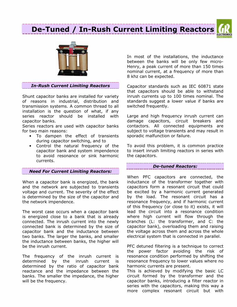
De-Tuned / In-Rush Current Limiting Reactors
In-Rush Current Limiting Reactors
Shunt capacitor banks are installed for variety of reasons in industrial, distribution and transmission systems. A common thread to all installation is the question of what, if any series reactor should be installed with capacitor banks. Series reactors are used with capacitor banks for two main reasons:
• To dampen the effect of transients during capacitor switching, and to
• Control the natural frequency of the capacitor bank and system impendence to avoid resonance or sink harmonic currents.
Need For Current Limiting Reactors:
When a capacitor bank is energized, the bank and the network are subjected to transients voltage and current. The severity of the effect is determined by the size of the capacitor and the network impendence. The worst case occurs when a capacitor bank is energized close to a bank that is already connected. The inrush current into the newly connected bank is determined by the size of capacitor bank and the inductance between two banks. The larger the banks, and smaller the inductance between banks, the higher will be the inrush current. The frequency of the inrush current is determined by the inrush current is determined by the ratio of capacitor bank reactance and the impedance between the banks. The smaller the impedance, the higher will be the frequency.
In most of the installations, the inductance between the banks will be only few micro-Henry, a peak current of more than 150 times nominal current, at a frequency of more than 8 khz can be expected. Capacitor standards such as IEC 60871 state that capacitors should be able to withstand inrush currents up to 100 times nominal. The standards suggest a lower value if banks are switched frequently. Large and high frequency inrush current can damage capacitors, circuit breakers and contactors. All connected equipments are subject to voltage transients and may result in sporadic malfunction or failure. To avoid this problem, it is common practice to insert inrush limiting reactors in series with the capacitors.
De-tuned Reactors:
When PFC capacitors are connected, the inductance of the transformer together with capacitors form a resonant circuit that could be excited by a harmonic current generated by the load. The resonant circuit has a resonance frequency, and if harmonic current of this frequency (or close to it) exists, it will lead the circuit into a resonance condition where high current will flow through the branches (L: the transformer, and C: the capacitor bank), overloading them and raising the voltage across them and across the whole electrical system that is connected in parallel. PFC detuned filtering is a technique to correct the power factor avoiding the risk of resonance condition performed by shifting the resonance frequency to lower values where no harmonic currents are present. This is achieved by modifying the basic LC circuit formed by the transformer and the capacitor banks, introducing a filter reactor in series with the capacitors, making this way a more complex resonant circuit but with
desired feature of having a resonance frequency below the first existing harmonic. This way it is not possible to have a real resonance condition. Besides this main objective, the reactor connected in series with the capacitors form a series resonant circuit with a certain tuning frequency at which the branch will offer a low impedance path. Filtering of harmonic currents and “cleaning” of the gird will be achieved. Components for PFC detuned filters must be carefully selected according to the desired PFC purpose, to the harmonic present in the system, to some features of the system like short circuit power and impedances, to the desired filtering effect and to the characteristics of the resonant circuit configured. For example, the voltage across the capacitors will be higher than the nominal grid voltage when they have a reactor connected in series. The reactors must be selected in line with the inductance value to obtain the desired tuning frequency and the current capability high enough for the harmonic current absorption that can be expected. Tuning frequency is usually indirectly referred to as the detuning factor p and expressed as a percentage. (Value will be in 5.67or 7 or 14) If De-tuned reactor is described as 7%, infers that the reactor reactance is 7% of the capacitor reactance at the fundamental frequency.
De-tuned reactor technical data:
Voltage harmonics : U3 = 0.5% UR : U5 = 6% UR : U7 = 5% UR : U11 = 3.5%UR :U13 = 3% UR Effective current : √ I1² + I3² + …….. I13² Fundamental Current = 1.06 X IR (50Hz Current of capacitor) Voltage : 400, 415, 440, 480V Capacity : 5………….. 100KVAR
De-tuning Factor : 5.67%, 7%, 14% Cooling : Natural Class of Insulation : F 155 Deg.
Reactor Installation:
GR Reactors are available in open construction and with enclosure. Open Reactors are designed for mounting within appropriate electrical equipment enclosure. Reactors rated 80A and under are designed for mounting in both vertical and horizontal position. Larger reactors must be mounted in horizontal position typically on the floor of the enclosure. Allow side clearances of 100mm and vertical clearances of 150mm for proper heat dissipation and access. The part of the enclosure containing Line Reactors must be forced ventilated according the dissipated power. Minimum Air flow must be: F= 0.4 X Ps in (Ps = power dissipated by the Line reactor)
Limited Warranty:
• GR Electronics warrants to the original purchaser only that the reactors will be free from defects in material and workmanship for period of one year from the date of shipment.
• Our liability is limited only to the repair or replacement of product defective in materials or workmanships. GR shall not in any event, be liable for incidental damages or consequential damage or economic loss.
• This warranty shall not apply to the defects that occur to improper storage / handling or misuse.
Tests conducted at our works
• Visual inspection for general workmanship, Quality and finish.
• Measurement of impedance value @ rated current.
• Measurement of Insulation resistance with Insulation tester.
• High Voltage test at 3KV for one minute between live parts to earth

Harmonic Filters
The use of Non-linear loads have grown
rapidly in recent years. With this growth has come concern over the level of current harmonics generated by such equipments.
Harmonic currents and voltage distortion these current creates, can have de-vasting
effects on a power distribution system and its connected equipment.
Typical Problems:
Non-linear loads are products that draw non-sinusoidal current from the distribution
line. This non-sinusoidal current derived from waveforms that combine the
fundamental frequency with integral multiples of that frequency. The resulting harmonic distortion is a basic result of the
operation of non-linear loads. When these type of loads are a significant portion of an
electrical systems, harmonic distortion may begin to cause problems throughout the entire systems. These problems range from
poor power factor, transformer distribution equipment over heating, random breaker
tripping, or even sensitive equipment failure.
Superior solution- Harmonic Filters:
Present method of harmonic treatments (use of line chokes) are often unreliable,
moderately effective or too costly. The innovative GR Harmonic filter is a proven
advance in the area of passive harmonic mitigation. No other device on the market can meet the most stringent limits of IEEE
std 519 at an equivalent size and cost. When the application calls for a truly cost effective harmonic solution, the harmonic
filter is only logical solution.
IEEE-519 1992 Harmonic distortion
limits:
IEEE-519 set forth distortion limits for
power users. These limits defined the maximum current and voltage distortion percentages allowable at the point of
common coupling, commonly referred to as the PCC, under full load, can be found
below.
• Where Isc= Short circuit current • Where Isc= Short circuit current
• TDD = Total Demand Distortion
IEEE-519 Voltage distortion limits:
• Special application (hospital, airport) 3% • General system application 5% • Dedicated systems (100% converted
Loads) 10%
Harmonic Filter Design Requirements:
• Will meet IEEE-519 standard for both current and voltage distortion
• Input current demand distortion <8% over entire operating range
• Power factor 0.98 lagging to 0.95 leading over the normal operating range
• Compatible with generators since
capacitive reactance is <15% of rated KVA even under light loads
• Will not resonate with other power system
components or attract line side harmonics
Isc/IL TDD
<20 5%
20<50 8%
50<100 12%
100<1000 15%
>1000 20%