technical evaluation report ter 1711-01
TRANSCRIPT
Technical Evaluation Report TER 1711-01
SPAX® 5/16" PowerLag® Fasteners for Use in Deck Ledger Board Applications
Altenloh, Brinck & Company
U.S., Inc.
Product: SPAX® 5/16" PowerLag®
Fasteners
Issue Date: March 29, 2018 Revision Date: March 18, 2021
Subject to Renewal: July 1, 2022
TER 1711-01
SPAX® 5/16" POWERLAG® FASTENERS FORUSE IN DECK LEDGER BOARD APPLICATIONS © 2021 DRJ ENGINEERING, LLC
SUBJECT TO RENEWAL 7/1/2022 PAGE 2 OF 13
COMPANY INFORMATION:
Altenloh, Brinck & Company U.S., Inc.
2105 County Rd 12C Bryan, OH 43506-8301
419-636-6715
800-443-9602
spax.us
DIVISION: 06 00 00 - WOOD, PLASTICS AND COMPOSITES
SECTION: 06 11 00 - Wood Framing
SECTION: 06 15 00 - Wood Decking
1 PRODUCT EVALUATED1 1.1 SPAX® 5/16" PowerLag® Fasteners
2 APPLICABLE CODES AND STANDARDS2,3 2.1 Codes
2.1.1 IBC—12, 15, 18: International Building Code® 2.1.2 IRC—12, 15, 18: International Residential Code®
2.2 Standards and Referenced Documents 2.2.1 ANSI/AWC NDS: National Design Specification (NDS) for Wood Construction 2.2.2 ASTM A153: Standard Specification for Zinc Coating (Hot-Dip) on Iron and Steel Hardware 2.2.3 ASTM A510: Standard Specification for General Requirements for Wire Rods and Coarse Round Wire,
Carbon Steel, and Alloy Steel 2.2.4 ASTM B117: Standard Practice for Operating Salt Spray (Fog) Apparatus 2.2.5 ASTM D1761: Standard Test Methods for Mechanical Fasteners in Wood 2.2.6 ASTM D2395: Standard Test Methods for Density and Specific Gravity (Relative Density) of Wood and Wood-
Based Materials 2.2.7 ASTM D4442: Standard Test Methods for Direct Moisture Content Measurement of Wood and Wood-Based
Materials 2.2.8 ASTM F1575: Standard Test Methods for Determining Bending Yield Moment of Nails 2.2.9 ASTM G85: Standard Practice for Modified Salt Spray (Fog) Testing
1 For more information, visit drjcertification.org or call us at 608-310-6748. 2 Unless otherwise noted, all references in this TER are from the 2018 version of the codes and the standards referenced therein. This material, design, or method of construction also complies with the 2000-2015 versions of the referenced codes and the standards referenced therein. 3 All terms defined in the applicable building codes are italicized.
TER 1711-01
SPAX® 5/16" POWERLAG® FASTENERS FORUSE IN DECK LEDGER BOARD APPLICATIONS © 2021 DRJ ENGINEERING, LLC
SUBJECT TO RENEWAL 7/1/2022 PAGE 3 OF 13
3 PERFORMANCE EVALUATION 3.1 PowerLag® fasteners were evaluated to determine their ability to provide code complying attachment of deck
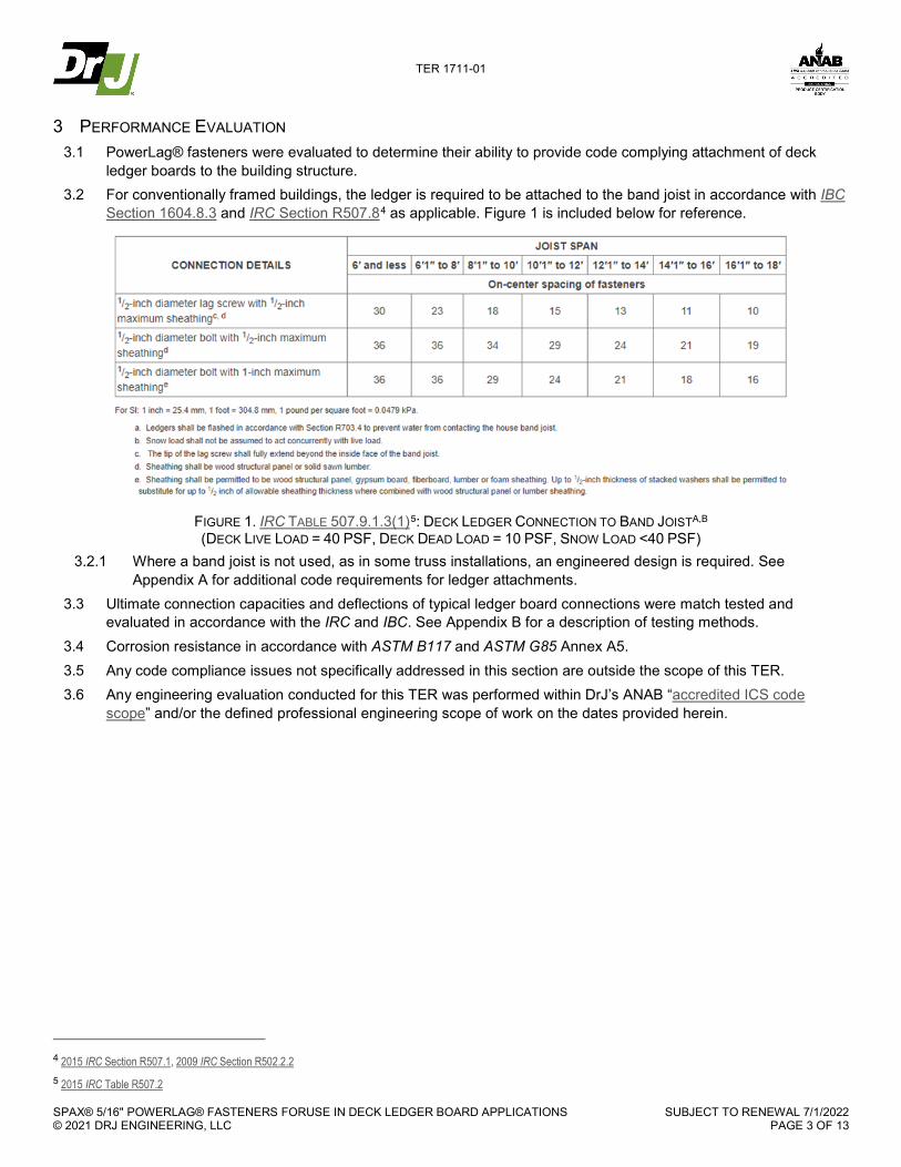
ledger boards to the building structure. 3.2 For conventionally framed buildings, the ledger is required to be attached to the band joist in accordance with IBC
Section 1604.8.3 and IRC Section R507.84 as applicable. Figure 1 is included below for reference.
FIGURE 1. IRC TABLE 507.9.1.3(1)5: DECK LEDGER CONNECTION TO BAND JOISTA,B (DECK LIVE LOAD = 40 PSF, DECK DEAD LOAD = 10 PSF, SNOW LOAD <40 PSF)
3.2.1 Where a band joist is not used, as in some truss installations, an engineered design is required. See Appendix A for additional code requirements for ledger attachments.
3.3 Ultimate connection capacities and deflections of typical ledger board connections were match tested and evaluated in accordance with the IRC and IBC. See Appendix B for a description of testing methods.
3.4 Corrosion resistance in accordance with ASTM B117 and ASTM G85 Annex A5. 3.5 Any code compliance issues not specifically addressed in this section are outside the scope of this TER. 3.6 Any engineering evaluation conducted for this TER was performed within DrJ’s ANAB “accredited ICS code
scope” and/or the defined professional engineering scope of work on the dates provided herein.
4 2015 IRC Section R507.1, 2009 IRC Section R502.2.2 5 2015 IRC Table R507.2
TER 1711-01
SPAX® 5/16" POWERLAG® FASTENERS FORUSE IN DECK LEDGER BOARD APPLICATIONS © 2021 DRJ ENGINEERING, LLC
SUBJECT TO RENEWAL 7/1/2022 PAGE 4 OF 13
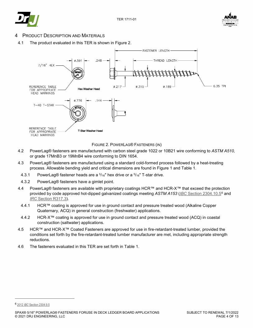
4 PRODUCT DESCRIPTION AND MATERIALS 4.1 The product evaluated in this TER is shown in Figure 2.
FIGURE 2. POWERLAG® FASTENERS (IN)
4.2 PowerLag® fasteners are manufactured with carbon steel grade 1022 or 10B21 wire conforming to ASTM A510, or grade 17MnB3 or 19MnB4 wire conforming to DIN 1654.
4.3 PowerLag® fasteners are manufactured using a standard cold-formed process followed by a heat-treating process. Allowable bending yield and critical dimensions are found in Figure 1 and Table 1.
4.3.1 PowerLag® fastener heads are a 5/16" hex drive or a 5/16" T-star drive. 4.3.2 PowerLag® fasteners have a gimlet point.
4.4 PowerLag® fasteners are available with proprietary coatings HCR™ and HCR-X™ that exceed the protection provided by code approved hot-dipped galvanized coatings meeting ASTM A153 (IBC Section 2304.10.56 and IRC Section R317.3).
4.4.1 HCR™ coating is approved for use in ground contact and pressure treated wood (Alkaline Copper Quaternary, ACQ) in general construction (freshwater) applications.
4.4.2 HCR-X™ coating is approved for use in ground contact and pressure treated wood (ACQ) in coastal construction (saltwater) applications.
4.5 HCR™ and HCR-X™ Coated Fasteners are approved for use in fire-retardant-treated lumber, provided the conditions set forth by the fire-retardant-treated lumber manufacturer are met, including appropriate strength reductions.
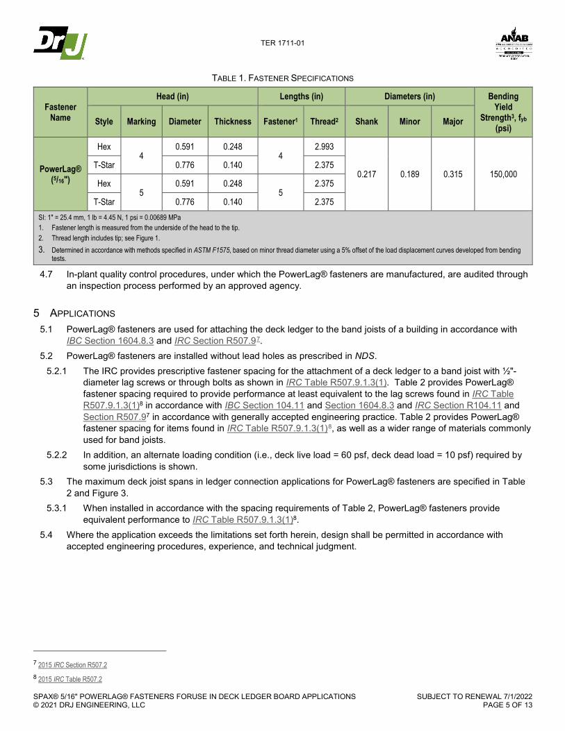
4.6 The fasteners evaluated in this TER are set forth in Table 1.
6 2012 IBC Section 2304.9.5
TER 1711-01
SPAX® 5/16" POWERLAG® FASTENERS FORUSE IN DECK LEDGER BOARD APPLICATIONS © 2021 DRJ ENGINEERING, LLC
SUBJECT TO RENEWAL 7/1/2022 PAGE 5 OF 13
TABLE 1. FASTENER SPECIFICATIONS
Fastener Name
Head (in) Lengths (in) Diameters (in) Bending Yield
Strength3, fyb (psi)
Style Marking Diameter Thickness Fastener1 Thread2 Shank Minor Major
PowerLag® (5/16")
Hex 4
0.591 0.248 4
2.993
0.217 0.189 0.315 150,000 T-Star 0.776 0.140 2.375
Hex 5
0.591 0.248 5
2.375
T-Star 0.776 0.140 2.375 SI: 1" = 25.4 mm, 1 lb = 4.45 N, 1 psi = 0.00689 MPa 1. Fastener length is measured from the underside of the head to the tip. 2. Thread length includes tip; see Figure 1. 3. Determined in accordance with methods specified in ASTM F1575, based on minor thread diameter using a 5% offset of the load displacement curves developed from bending
tests.
4.7 In-plant quality control procedures, under which the PowerLag® fasteners are manufactured, are audited through an inspection process performed by an approved agency.
5 APPLICATIONS 5.1 PowerLag® fasteners are used for attaching the deck ledger to the band joists of a building in accordance with
IBC Section 1604.8.3 and IRC Section R507.97. 5.2 PowerLag® fasteners are installed without lead holes as prescribed in NDS.
5.2.1 The IRC provides prescriptive fastener spacing for the attachment of a deck ledger to a band joist with ½"-diameter lag screws or through bolts as shown in IRC Table R507.9.1.3(1). Table 2 provides PowerLag® fastener spacing required to provide performance at least equivalent to the lag screws found in IRC Table R507.9.1.3(1)8 in accordance with IBC Section 104.11 and Section 1604.8.3 and IRC Section R104.11 and Section R507.97 in accordance with generally accepted engineering practice. Table 2 provides PowerLag® fastener spacing for items found in IRC Table R507.9.1.3(1)8, as well as a wider range of materials commonly used for band joists.
5.2.2 In addition, an alternate loading condition (i.e., deck live load = 60 psf, deck dead load = 10 psf) required by some jurisdictions is shown.
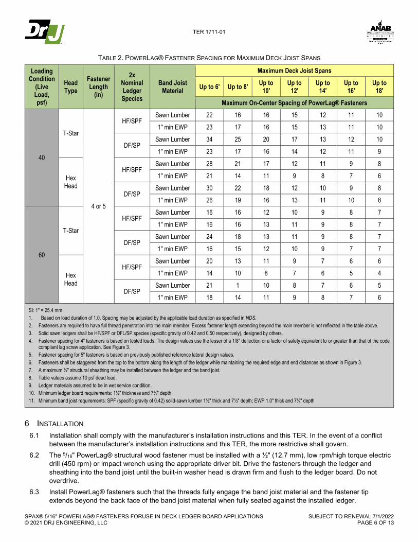
5.3 The maximum deck joist spans in ledger connection applications for PowerLag® fasteners are specified in Table 2 and Figure 3.
5.3.1 When installed in accordance with the spacing requirements of Table 2, PowerLag® fasteners provide equivalent performance to IRC Table R507.9.1.3(1)8.
5.4 Where the application exceeds the limitations set forth herein, design shall be permitted in accordance with accepted engineering procedures, experience, and technical judgment.
7 2015 IRC Section R507.2 8 2015 IRC Table R507.2
TER 1711-01
SPAX® 5/16" POWERLAG® FASTENERS FORUSE IN DECK LEDGER BOARD APPLICATIONS © 2021 DRJ ENGINEERING, LLC
SUBJECT TO RENEWAL 7/1/2022 PAGE 6 OF 13
TABLE 2. POWERLAG® FASTENER SPACING FOR MAXIMUM DECK JOIST SPANS
Loading Condition
(Live Load, psf)
Head Type
Fastener Length
(in)
2x Nominal Ledger Species
Band Joist Material
Maximum Deck Joist Spans
Up to 6' Up to 8' Up to 10'
Up to 12'
Up to 14'
Up to 16'
Up to 18'
Maximum On-Center Spacing of PowerLag® Fasteners
40
T-Star
4 or 5
HF/SPF Sawn Lumber 22 16 16 15 12 11 10
1" min EWP 23 17 16 15 13 11 10
DF/SP Sawn Lumber 34 25 20 17 13 12 10
1" min EWP 23 17 16 14 12 11 9
Hex Head
HF/SPF Sawn Lumber 28 21 17 12 11 9 8
1" min EWP 21 14 11 9 8 7 6
DF/SP Sawn Lumber 30 22 18 12 10 9 8
1" min EWP 26 19 16 13 11 10 8
60
T-Star
HF/SPF Sawn Lumber 16 16 12 10 9 8 7
1" min EWP 16 16 13 11 9 8 7
DF/SP Sawn Lumber 24 18 13 11 9 8 7
1" min EWP 16 15 12 10 9 7 7
Hex Head
HF/SPF Sawn Lumber 20 13 11 9 7 6 6
1" min EWP 14 10 8 7 6 5 4
DF/SP Sawn Lumber 21 1 10 8 7 6 5
1" min EWP 18 14 11 9 8 7 6
SI: 1" = 25.4 mm 1. Based on load duration of 1.0. Spacing may be adjusted by the applicable load duration as specified in NDS. 2. Fasteners are required to have full thread penetration into the main member. Excess fastener length extending beyond the main member is not reflected in the table above. 3. Solid sawn ledgers shall be HF/SPF or DFL/SP species (specific gravity of 0.42 and 0.50 respectively), designed by others. 4. Fastener spacing for 4" fasteners is based on tested loads. The design values use the lesser of a 1/8" deflection or a factor of safety equivalent to or greater than that of the code
compliant lag screw application. See Figure 3. 5. Fastener spacing for 5" fasteners is based on previously published reference lateral design values. 6. Fasteners shall be staggered from the top to the bottom along the length of the ledger while maintaining the required edge and end distances as shown in Figure 3. 7. A maximum ½" structural sheathing may be installed between the ledger and the band joist. 8. Table values assume 10 psf dead load. 9. Ledger materials assumed to be in wet service condition. 10. Minimum ledger board requirements: 1½" thickness and 7½" depth 11. Minimum band joist requirements: SPF (specific gravity of 0.42) solid-sawn lumber 1½" thick and 7½" depth; EWP 1.0" thick and 7¼" depth
6 INSTALLATION 6.1 Installation shall comply with the manufacturer’s installation instructions and this TER. In the event of a conflict
between the manufacturer’s installation instructions and this TER, the more restrictive shall govern. 6.2 The 5/16" PowerLag® structural wood fastener must be installed with a ½" (12.7 mm), low rpm/high torque electric
drill (450 rpm) or impact wrench using the appropriate driver bit. Drive the fasteners through the ledger and sheathing into the band joist until the built-in washer head is drawn firm and flush to the ledger board. Do not overdrive.
6.3 Install PowerLag® fasteners such that the threads fully engage the band joist material and the fastener tip extends beyond the back face of the band joist material when fully seated against the installed ledger.

TER 1711-01
SPAX® 5/16" POWERLAG® FASTENERS FORUSE IN DECK LEDGER BOARD APPLICATIONS © 2021 DRJ ENGINEERING, LLC
SUBJECT TO RENEWAL 7/1/2022 PAGE 7 OF 13
6.4 Lead holes are not required. 6.5 Figure 3 shows a detail of the PowerLag® fastener deck connection, including minimum edge and end distances. 6.6 Stagger the PowerLag® fasteners from the top to the bottom along the length of the ledger while maintaining the
required edge and end distances.
FIGURE 3. POWERLAG® FASTENER DECK CONNECTION
6.7 For applications outside the scope of this TER, an engineered design is required.
7 SUBSTANTIATING DATA 7.1 Testing has been performed under the supervision of a professional engineer and/or under the requirements of
ISO/IEC 17025 as follows: 7.1.1 Bending yield, shear, and tensile strength testing in accordance with ASTM F1575 7.1.2 Lateral resistance and withdrawal resistance testing in accordance with ASTM D1761 7.1.3 Head pull-through resistance testing in accordance with ASTM D1037 7.1.4 Corrosion resistance testing in accordance with ASTM B117 and ASTM G85, Annex A5 7.1.5 Deck ledger assembly testing in general accordance with ASTM D1761
7.2 DCA 6, Prescriptive Residential Wood Deck Construction Guide; AF&PA; 2010 7.3 Information contained herein is the result of testing and/or data analysis by sources which conform to IBC Section
1703 and/or professional engineering regulations. DrJ relies upon accurate data to perform its ISO/IEC 17065 evaluations.
TER 1711-01
SPAX® 5/16" POWERLAG® FASTENERS FORUSE IN DECK LEDGER BOARD APPLICATIONS © 2021 DRJ ENGINEERING, LLC
SUBJECT TO RENEWAL 7/1/2022 PAGE 8 OF 13
7.4 Where appropriate, DrJ’s analysis is based on provisions that have been codified into law through state or local adoption of codes and standards. The providers of the codes and standards are legally responsible for their content. DrJ analysis may use code-adopted provisions as a control sample. A control sample versus a test sample establishes a product as being equivalent to that prescribed in this code in quality, strength, effectiveness, fire resistance, durability, and safety. Where the accuracy of the provisions provided herein is reliant upon the published properties of materials, DrJ relies upon the grade mark, grade stamp, mill certificate, and/or test data provided by material suppliers to be minimum properties. DrJ analysis relies upon these properties to be accurate.
8 FINDINGS 8.1 When used in accordance with this TER and the manufacturer’s installation instructions, PowerLag® fasteners
are a suitable alternative to the requirements of the IBC Section 1604.8.3 and IRC Section R507.99. 8.1.1 PowerLag® fasteners with HCR™ coating is approved for use in ground contact and pressure treated wood
(ACQ) in general construction (freshwater) applications. 8.1.2 PowerLag® fasteners with HCR-X™ coating is approved for use in ground contact and pressure treated wood
(ACQ) in coastal construction (saltwater) applications. 8.2 HCR™ and HCR-X™ Coated Fasteners are approved for use in fire-retardant-treated lumber, provided the
conditions set forth by the fire-retardant-treated lumber manufacturer are met, including appropriate strength reductions.
8.3 This product has been evaluated in the context of the codes listed in Section 2 and is compliant with all known state and local building codes. Where there are known variations in state or local codes applicable to this TER, they are listed here.
8.3.1 No known variations 8.4 Building codes require data from valid research reports be obtained from approved sources (i.e., licensed
registered design professionals [RDPs]). 8.4.1 Building official approval of a licensed RDP is performed by verifying the RDP and/or their business entity is
listed by the licensing board of the relevant jurisdiction. 8.5 Agencies who are accredited through ISO/IEC 17065 have met the code requirements for approval by the
building official. DrJ is an ISO/IEC 17065 ANAB-Accredited Product Certification Body – Accreditation #1131 and employs RDPs.
8.6 Through ANAB accreditation and the IAF MLA, DrJ certification can be used to obtain product approval in any jurisdiction or country that has IAF MLA Members & Signatories to meet the Purpose of the MLA – “certified once, accepted everywhere.”
8.7 IBC Section 104.11 (IRC Section R104.11 and IFC Section 104.9 are similar) states:
104.11 Alternative materials, design and methods of construction and equipment. The provisions of this code are not intended to prevent the installation of any material or to prohibit any design or method of construction not specifically prescribed by this code…Where the alternative material, design or method of construction is not approved, the building official shall respond in writing, stating the reasons the alternative was not approved.
9 CONDITIONS OF USE 9.1 PowerLag® fasteners covered by this TER shall be installed in accordance with Section 6 of this report and the
manufacturer’s installation instructions. 9.2 PowerLag® fastener spacing shall not exceed Table 2 for code compliance and the installation conditions
considered.
9 2015 IRC Section 507.2
TER 1711-01
SPAX® 5/16" POWERLAG® FASTENERS FORUSE IN DECK LEDGER BOARD APPLICATIONS © 2021 DRJ ENGINEERING, LLC
SUBJECT TO RENEWAL 7/1/2022 PAGE 9 OF 13
9.3 For conditions not covered in this TER, connections shall be designed in accordance with generally accepted engineering practice.
9.4 PowerLag® fasteners are produced under a quality control program subject to periodic inspections in accordance with IBC Section 1703.5.2.
9.5 Where required by the building official, also known as the authority having jurisdiction (AHJ) in which the project is to be constructed, this TER and the installation instructions shall be submitted at the time of permit application.
9.6 Any generally accepted engineering calculations needed to show compliance with this TER shall be submitted to the AHJ for review and approval.
9.7 Design loads shall be determined in accordance with the building code adopted by the jurisdiction in which the project is to be constructed and/or by the building designer (e.g., owner or RDP).
9.8 At a minimum, this product shall be installed per Section 6 of this TER. 9.9 This product has an internal quality control program and a third-party quality assurance program in accordance
with IBC Section 104.4 and Section 110.4 and IRC Section R104.4 and Section R109.2. 9.10 The actual design, suitability, and use of this TER, for any particular building, is the responsibility of the owner or
the owner's authorized agent. 9.11 This TER shall be reviewed for code compliance by the AHJ in concert with IBC Section 104. 9.12 The implementation of this TER for this product is dependent on the design, quality control, third-party quality
assurance, proper implementation of installation instructions, inspections required by IBC Section 110.3, and any other code or regulatory requirements that may apply.
10 IDENTIFICATION 10.1 The product(s) listed in Section 1.1 are identified by a label on the board or packaging material bearing the
manufacturer’s name, product name, TER number, and other information to confirm code compliance. 10.2 Additional technical information can be found at spax.us.
11 REVIEW SCHEDULE 11.1 This TER is subject to periodic review and revision. For the most recent version, visit drjcertification.org. 11.2 For information on the current status of this TER, contact DrJ Certification.

TER 1711-01
SPAX® 5/16" POWERLAG® FASTENERS FORUSE IN DECK LEDGER BOARD APPLICATIONS © 2021 DRJ ENGINEERING, LLC
SUBJECT TO RENEWAL 7/1/2022 PAGE 10 OF 13
APPENDIX A Code Requirements for Ledger Attachments
For guidance on designing the connection of the deck ledger to trusses where a band joist is not used, see SBCA’s Tech Note, Attachment of Residential Deck Ledger to Metal Pate Connected Wood Truss Floor System.
1) IRC Section R507.810 contains the following code requirements (IBC Section 1604.8.3 is similar):
a) Where supported by attachment to an exterior wall, decks shall be positively anchored to the primary structure and designed for both vertical and lateral loads.
i) Attachment shall not be accomplished by the use of toenails or nails subject to withdrawal.
2) IRC Section R507.9.1 details how vertical loads shall be transferred to band joists with ledgers:
a) IRC Section R507.9.1.1
Deck ledgers shall be a minimum 2-inch by 8-inch (51 mm by 203 mm) nominal, pressure-preservative-treated Southern pine, incised pressure-preservative-treated hem-fir, or approved, naturally durable, No. 2 grade or better lumber…
b) IRC Section R507.9.1.2
Band joists supporting a ledger shall be a minimum 2-inch-nominal (51 mm), spruce-pine-fir or better lumber or a minimum 1-inch by 9½-inch (25 mm x 241 mm) dimensional, Douglas fir or better, laminated veneer lumber. Band joists shall bear fully on the primary structure capable of supporting all required loads.
c) IRC Section R507.9.1.311 Fasteners used in deck ledger connections in accordance with Table R507.9.1.3(1) shall be hot-dipped galvanized or stainless steel and shall be installed in accordance with Table R507.9.1.3(2) and Figures R507.9.1.3(1) and R507.9.1.3(2).
IRC FIGURE R507.9.1.3(2): PLACEMENT OF LAG SCREWS AND BOLTS IN BAND JOISTS
d) Tables R507.9.1.3(1) and R507.9.1.3(2)12 cover the placement of lag screws or bolts in deck ledgers:
The tip of the lag screw shall fully extend beyond the inside face of the band joist
10 2012 IRC Section R507.1, 2015 IRC Section R507.1 11 2012 IRC Section R507.2, 2015 IRC Section R507.2 12 2012 IRC Section R507.2.1, 2015 IRC Table R507.2.1, Figure R507.2.1(1) and Figure R507.2.1(2)
TER 1711-01
SPAX® 5/16" POWERLAG® FASTENERS FORUSE IN DECK LEDGER BOARD APPLICATIONS © 2021 DRJ ENGINEERING, LLC
SUBJECT TO RENEWAL 7/1/2022 PAGE 11 OF 13
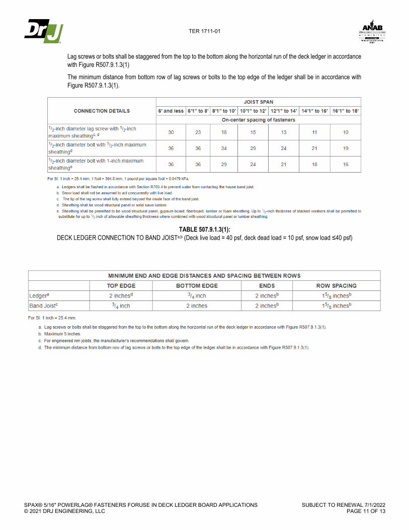
Lag screws or bolts shall be staggered from the top to the bottom along the horizontal run of the deck ledger in accordance with Figure R507.9.1.3(1)
The minimum distance from bottom row of lag screws or bolts to the top edge of the ledger shall be in accordance with Figure R507.9.1.3(1).
TABLE 507.9.1.3(1):
DECK LEDGER CONNECTION TO BAND JOISTa,b (Deck live load = 40 psf, deck dead load = 10 psf, snow load ≤40 psf)
TER 1711-01
SPAX® 5/16" POWERLAG® FASTENERS FORUSE IN DECK LEDGER BOARD APPLICATIONS © 2021 DRJ ENGINEERING, LLC
SUBJECT TO RENEWAL 7/1/2022 PAGE 12 OF 13
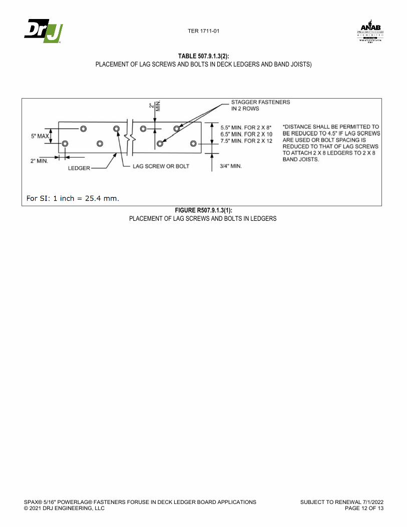
TABLE 507.9.1.3(2): PLACEMENT OF LAG SCREWS AND BOLTS IN DECK LEDGERS AND BAND JOISTS)
FIGURE R507.9.1.3(1): PLACEMENT OF LAG SCREWS AND BOLTS IN LEDGERS

TER 1711-01
SPAX® 5/16" POWERLAG® FASTENERS FORUSE IN DECK LEDGER BOARD APPLICATIONS © 2021 DRJ ENGINEERING, LLC
SUBJECT TO RENEWAL 7/1/2022 PAGE 13 OF 13
APPENDIX B Testing Procedure and Methodology
1. To determine the strength and load-deflection performance of the fasteners in a ledger connection, a two-joist
assembly with connection of a ledger to a band joist was created. Load was applied to the joists, which transferred load to the ledger via hangers. String potentiometers were placed along the bottom of the ledger to measure vertical deflection during the test, while a load cell attached to an actuator measured load applied. The band joist was fixed to prevent deflection and rotation during the test. To limit the variability, the comparison product was tested simultaneously with the PowerLag® fasteners with ledgers and band joists cut congruently from the same piece of lumber. Immediately after testing, a section was cut near each fastener location to determine the moisture content and oven-dry specific gravity of each piece of lumber.
2. The performance of the code defined lag screw connection was then compared to the performance of the PowerLag® fasteners in the ledger application built per the code requirements.
2.1. Testing was undertaken to directly compare fastener performance using matched lumber specimen testing where the PowerLag® fastener was tested side by side with ½" diameter lag screws (see Figure 3).
Figure 4: Single & Three-Fastener Setups
2.1.2. The testing and resulting analysis define comparative performance and the design parameters required for PowerLag® fasteners to be considered an equivalent alternative to the specified fasteners required by the building code in accordance with the provisions of IBC Section 104.11 and IRC Section R104.11.