tech - energiezuinige elektrische boiler · tech i. intended use the st-402 thermoregulator is...
TRANSCRIPT

tech
- 1 -

ST – 402N user's manual
Declaration of Conformity No. 35/2010
Hereby, we declare under sole responsibility that the ST-402N
230V 50Hz thermoregulator manufactured by TECH, W, 34-120
Andrychów, is compliant with the Regulation by the Ministry of
Economy. (Journal of Laws Dz.U. 155 Item 1089) of July 21,
2007 implementing provisions of the Low Voltage Directive
(LVD) 2006/95/EC of January 16, 2007.
The ST-402N controller has been tested for
electromagnetic compatibility (EMC) with optimal loads
applied.
For compliance assessment, harmonized standards were
used:
PN-EN 60730-2-9:2006.
Paweł Jura, Janusz Master
- 2 -

tech
ATTENTION!High voltage!
Make sure the regulator is disconnected from
the mains before working on the power
supply (cable connections, device
installation, etc.)!
All connection works must only be carried
out by qualified electricians.
Before activating the controller, measure the
motor resetting efficiency and inspect wire
insulation.
- 3 -

ST – 402N user's manual
- 4 -

tech
I. Intended Use The ST-402 thermoregulator is intended for use with solar collectors in different configurations. The device is used to control collector pumps (or a pump and a valve) based on a temperature measurement at the solar batteries and at the accumulation tank (two tanks). It is also possible to connect optional devices: circulation pump, electric heater, or send a fire-up signal to the central heating boiler.
It is possible to control the circulation pump and input a fire-up signal into the central heating boiler directly from the controller. In case of the heater, it is required to fit an additional signal relay.
II. Principle of OperationDescription of the control panel in a sample configuration
The device is controlled with an buttons. Entering to main menu or confirming the settings is followed by pressing the menu button. Using the Plus and Minus button customer can easily navigate in each menu. To accept the selected submenu, press the Menu button. To go to the main page (or higher menu level), use the Exit button. All settings are changed in the same manner.
III. User’s MenuIII.a) Main PageDuring normal operation, the graphic display shows the Main Page that contains, apart from the selected configuration, the following information:- operation mode (or type of alarm),- current time,- collector temperature,- current heat storage temperature,- temperatures of all additional sensors depending on configuration.
To the right of the screen, the following icons are displayed:- 5 -
COLLECTORTEMPERATURE
COLLECTORPUMP
TIME
COLLECTOR 2TEMPERATURE
MENU
PLUS
EXIT
SWITCHINGVALVE
OPERATION MODEHEAT
STORAGE
TEMPERATURE
MINUS
OPERATION MODE,OPTIONAL
DEVICEACTIVATED

ST – 402N user's manual 1. Icon of the active operation mode:
Automatic operation mode
Collector defrosting mode
Holiday mode
Collector overheating (alarm mode)
Sensor failure (alarm mode)
2. Icon of the active optional device (peripherals):
Circulation pump
PLT (pellet) boiler fire-up
Heater
When one of the sensors is damaged, an additional icon starts to flash in the area where the temperature of the damaged sensor is normally displayed, to indicate which sensor has been disconnected or damaged.
In addition to the above, a pump icon (revolves if in operation) or/and valve icon (with an indication of the current circulation route) is displayed on the system configuration diagram.
III.b) Operation Mode With this function, you can select an operation mode. 1. Automatic mode.
In the automatic mode, the pump is running if the minimum temperature difference between the collector and the tank is reached (the temperature difference at which the pump is started is defined by the "Solar Pump Delta" function in: SERVICE MENU > Accumulation Tank > Solar Pump Delta). The pump continues to run until the setpoint temperature is reached (the setpoint temperature is set with: SERVICE MENU > Accumulation Tank > Setpoint Temperature) or until the collector temperature and the tank temperature equalize (in which case the pump is restarted when the temperature at the collector rises above the tank temperature by the value of solar pump delta). Once the pump is shut off after the setpoint temperature has been reached, it will be restarted if the temperature drops below the setpoint value by the value of tank hysteresis (the hysteresis value is set with: SERVICE MENU > Accumulation Tank > Storage Hysteresis). 2. Collector Defrosting.
With this function, you can manually start the collector pump in order to
- 6 -

tech
melt snow built up on the solar panels. The mode remains active for a period defined by the user. Then the controller returns to the automatic mode (the defrosting time is set with: SERVICE MENU > Solar Collector > Defrosting Time). The function can be deactivated manually by selecting another operation mode. 3. Holiday Mode.
When the holiday mode is enabled, during daytime hours (from 600 a.m. until 1000 p.m.), the pump runs as in the automatic mode, whereas during night hours (from 1000 p.m. until 600 a.m.), the pump is started only if the collector temperature is lower than the tank temperature so that the tank can be cooled. ATTENTION >You can change the daytime cycle and night cycle activation hour using the "DAY FROM" and "NIGHT FROM" settings.< 4. Manual Mode.
In this function, the user can enable or disable (by pressing the menu) the following: - solar pump,- second solar pump or switching valve,– optional device (voltage-free signal, e.g. for firing up of a pellet boiler).
III.c) Peripherals Depending on the settings in the service menu you may see an option displayed here that will allow you to change specific parameters for your selected peripheral: ◦ Circulating pump◦ Lighting of pellet boiler◦ Heater◦ Output setting identical to solar pump◦ Output in reverse setting to solar pumpTemperature threshold output
III.d) ClockWith this function, you can set the current time according to which
the controller is to operate.
III.e) BacklightThis item is used to adjust the display brightness. Adjustments will be
made after about ten or so seconds of inactivity.
III.f) Language VersionYou can select the language version for the controller.
III.g) Alarm soundThis feature allows you to enable or disable the audio signal that goes
off when an alarm is activated.
III.h) Energy calculation This function allows the user to see value, describing the following
- 7 -

ST – 402N user's manualparameters:- total energy obtained as a result of the solar collector operation,- total pump operation time
III.i) InformationWhen this option is selected, the logo of the manufacturer is displayed
together with the software version.
IV. Service MenuTo access the service settings, select the SERVICE MENU option and
then use the pulser to select the code 112 and confirm your selection by pressing the knob. To return to the main view screen (to exit the service menu), press the EXIT key a few times or wait about 30 seconds (the device will automatically exit service mode). You can also enter the service menu by pressing and holding down the exit button and pressing the pulser knob (this option can be disabled in the service settings).
IV.a) Installation diagramFor the solar system to work properly it is necessary to select the proper
installation diagram (SERVICE MENU > INSTALLATION DIAGRAM) and properly configure the additional options of your selected system (SERVICE MENU > INSTALLATION OPTIONS). NOTE When selecting your installation diagram the temperature sensors show their respective numbers instead of their temperature readings. This numbering should be followed to connect the appropriate sensors in the right places (from left to right): (1) – collector sensor (PT1000), (2) – storage unit sensor (PT1000),(3) –additional sensor 1 (PT1000), (4) - additional sensor 2 (PT1000).
IV.a.1) Diagram 1/12Installation 1/12 supports: collector pump, accumulator tank, one direction in the position of the collectors, additional peripherals.Installation sensors: collector sensor,accumulator tank sensor.
IV.a.2) Diagram 2/12
Installation 2/12 supports: collector pump, switching valve, accumulator tank, one direction in the position of the collectors,
- 8 -

tech additional peripherals.Installation sensors: collector sensor, two sensors of accumulator tank.
Additional installation options: valve hysteresis
The tank will be first heated up at its top section (where hot water for domestic use is collected), and after that part of the tank has been heated up the valve switches the circulation system over to the second part of the tank. The valve will switch back to its previous setting after the prioritized part of the tank cools down by the valve hysteresis value (temperature difference between the two parts of the tank).
IV.a.3) Diagram 3/12
Installation 3/12 supports: two collector pumps (the pumps function independently, each according to its own circulation system), accumulator tank, two directions in the positions of the collectors, additional peripherals.
Installation sensors: two collector sensors, accumulator tank sensor.Note: The settings of the solar collector options (SERVICE MENU > SOLAR COLLECTOR) apply equally to the collectors positioned in both directions.
IV.a.4) Diagram 4/12Installation 4/12 supports: collector pump, switching valve, accumulator tank, two directions in the positions of the
collectors, additional peripherals.Installation sensors: two collector sensors, accumulator tank sensor.
Additional installation options: collector delta
Only on heating circuit is active in this configuration. The switching valve is to switch the circuit onto the collector which currently has a
- 9 -

ST – 402N user's manualtemperature higher by at least the collector delta value (temperature difference between the two collectors).
IV.a.5) Diagram 5/12Installation 5/12 supports: collector pump, booster pump (Pump 2), accumulator tank, one direction in the position of the collectors, additional peripherals.Installation sensors: collector sensor, two KTY sensors of accumulator tank, boiler temperature sensor.
Additional installation options: delta value for activation
This installation model includes an additional circuit for heating up the tank using the central heating boiler. If the tank temperature is lower than the set-point temperature of the tank by at least the set-point value of activation delta (which is the difference between the set-point and current temperatures of the tank), the booster pump (from the boiler) will be activated to reheat the accumulator tank (provided that the temperature of the boiler is higher than the temperature of the tank). This setting will be active only between the times set by the user ("from, to"). from to
These settings are used to enter the times ("from, to ') when the central heating boiler circuit used to the heat up the accumulator tank is to be active.
IV.a.6) Diagram 6/12Installation 6/12 supports: collector pump, switching valve, two accumulator tanks, one direction in the position of the collectors, additional peripherals.Installation sensors: collector sensor, accumulator tank sensors.
Additional installation options: set-point temperature for tank 2
If the preset temperature of the first tank is reached, the valve will activate the second tank circuit. You can use this function to enter the set-point temperature of the second - 10 -

tech
tank. hysteresis value for tank 2
After the set-point temperature is reached the pump will be switched off. The pump will be turned on again if the tank temperature falls below the set-point temperature by the hysteresis value for tank 2. valve hysteresis
This setting affects the control of the valve during the operations of cooling the collector in summer or emergency mode and when defrosting. The valve hysteresis value determines the temperature difference between the tanks, at which the valve is switched over to the opposite tank. maximum temperature for tank 2
With this option you can enter the maximum permissible safe temperature, up to which the second tank can be heated up in the event of the collector getting overheated.
IV.a.7) Diagram 7/12Installation 7/12 supports: two collector pumps, two accumulator tanks, one direction in the position of the collectors, additional peripherals.Installation sensors: collector sensor, accumulator tank sensors.
Additional installation options: set-point temperature for tank 2
This function is used to enter the set-point temperature of the second tank. After this temperature is reached collector pump 2 will turn off. hysteresis value for tank 2
After the set-point temperature is reached the pump will turn off. The pump will turn on again if the tank temperature falls below the set-point temperature by the hysteresis value for tank 2. maximum temperature for tank 2
With this option you can enter the maximum permissible safe temperature, up to which the second tank can be heated up in the event of the collector getting overheated. delta value for pump 2
This function is used to set the difference between the temperatures of the collector and the second tank, at which pump 2 will start to work (threshold value for pump activation). operation algorithm
With this option you can select pump operation modes. The pumps can be operated in the following modes:
a) priority for tank 1 – tank 1 is heated first (only pump 1 is active), and
- 11 -

ST – 402N user's manualafter the set-point temperature is reached pump 2 will turn on to heat up tank2.
b) parallel operation – the pumps operate independently, each within its own range (as per settings) and both tanks are heated simultaneously.
IV.a.8)Diagram 8/12Installation 8/12 supports: collector pump, second tank pump, two accumulator tanks, one direction in the position of the collectors, additional peripherals.Installation sensors: collector sensor, two sensors of the main accumulator tank. sensor of the additional accumulator tank.
Additional installation options: set-point temperature for tank 2
This function is used to enter the set-point temperature of the second tank. After this temperature is reached the tank 2 pump (collector pump 2) will turn off. hysteresis value for tank 2
After the set-point temperature is reached pump 2 will turn off. Pump 2 will turn on again if the tank temperature falls below the set-point temperature by the hysteresis value for tank 2. delta value for pump 2
This function is used to set the difference between the temperatures of tank 1 and tank 2, at which pump 2 will start to work (threshold value for the activation of pump 2). maximum temperature for tank 2
With this option you can enter the maximum permissible safe temperature, up to which the second tank can be heated up in the event of the collector getting overheated. operation algorithm
With this option you can select pump operation modes. The pumps can be operated in the following modes:
a) priority for tank 1 – tank 1 is heated first (only pump 1 is active), and after the set-point temperature is reached pump 2 will turn on to heat up the second tank. Pump 2 will be switched off after the set-point temperature of the second tank is reached or when the temperatures of both tanks equalize.
b) parallel operation – the pumps operate independently, each within its own range (as per settings) and both tanks are heated simultaneously (in parallel).
- 12 -

tech
IV.a.9) Diagram 9/12Installation 9/12 supports: collector pump, switching valve, accumulator tank, heat exchanger (heat receiver), one direction in the position of the collectors, additional peripherals.Installation sensors: collector sensor, accumulator tank sensor. heat exchanger sensor.
In addition to an accumulator tank a heat receiver is available as part of the installation (such as a swimming pool or central heating system), whose task is to release and not collect heat energy.Additional installation options set-point temperature for tank 2
This function is used to enter the set-point temperature of the second heat receiver (exchanger). After this temperature is reached the collector pump will turn off. hysteresis value for tank 2
After the set-point temperature of the heat receiver is reached the pump will turn off. The pump will turn on again after the temperature of the heat receiver drops below the set-point temperature by the hysteresis value for tank 2 (provided that tank 1 has been heated up and the valve is not switched over to the accumulator tank). valve hysteresis
When the preset temperature of the first tank is reached, the valve will activate the heat receiver circuit. The valve will switch back to its previous setting after the first tank cools down by the valve hysteresis value (temperature difference between the two tanks). maximum temperature for tank 2
With this option you can enter the maximum permissible safe temperature, up to which the second tank (heat receiver) can be heated up in the event of the collector getting overheated.
- 13 -

ST – 402N user's manualIV.a.10) Diagram 10/12
Installation 10/12 supports: collector pump, switching valve, accumulator tank, dual-function heater (heating up), one direction in the position of the collectors, additional peripherals.Installation sensors: collector sensor, two sensors of accumulator tank.
The installation works with a two-function heater used to heat up the circuit. If the tank temperature is too low, the valve switches over to the heater, which additionally heats up the water behind the tank.Additional installation options: heating up - off
This function is used to set a temperature point for the tank, below which the valve will switch over to the heating up circuit (two function heater).
IV.a.11) Diagram 11/12Installation 11/12 supports: collector pump, switching valve, accumulator tank, boiler return circuit, one direction in the position of the collectors, additional peripherals.
Installation sensors: collector sensor, two sensors of accumulator tank. boiler return circle.
The installation is equipped with a valve, which, when excess hot water is found in the tank, will switch over to the boiler return circuit to reheat it (release excess heat), which will result in solid fuel savings.Additional installation options: release threshold
This parameter is used to set the threshold temperature of the tank, at which the valve switches over to boiler return reheating mode. release hysteresis.
When the release threshold temperature is reached, the valve will activate the boiler return circuit. The valve will switch back to its previous setting after the tank cools down by the release hysteresis value.
- 14 -

tech
IV.a.11) Diagram 12/12Installation 12/12 supports :
➔ two colectors pump (pumps operate independently, each according to its own circulation system), ➔ accumulator tank,➔ two directions in the positions of the collectors,
➔ additional heat receiver,➔ switching valve, Instalation sensors:➔ two collector sensors,➔ sensors of the accumulator tank.,➔ additional heat exchanger sensor.
Note: Not selectable peripherals (option is grayed out in the main menu). In the peripherals place is connected switching valve which supports additional receiver. Additional installation options :-maximum temperature of additional receiver (maximum temperature for tank 2)- With this option you can enter the maximum permissible safe temperature, up to which the heat receiver, can be heated up in the event of the collector getting overheated.. -hysteresis of additional receiver (hysteresis value for tank 2) - When the release threshold temperature is reached, the valve will activate the boiler return circuit. The valve will switch back to its previous setting after the tank cools down by the release hysteresis value.
- 15 -
ST – 402N user's manual IV.b) Accumulator tank
When in this menu you can set all the parameters of the tank (thermal storage unit)
IV.b.1) Set-point temperatureThis function is used to adjust the preset temperature of the storage
unit. After this temperature is reached the collector pump will turn off.
IV.b.2) Maximum temperatureWith this option you can enter the maximum permissible safe
temperature, up to which the tank can be heated up in the event of the collector getting overheated.
If the collector temperature reaches the alarm (overheating) temperature, the pump will switch on automatically to cool down the heated collector, regardless of any set-point temperatures. The pump will run until the maximum storage unit temperature is reached or until the collector temperature drops by the alarm hysteresis value (see SERVICE MENU> Solar collector > Alarm hysteresis).
IV.b.3) Minimum tank temperature.This parameter is for declaring the minimum acceptable temperature value, down to which the tank will be allowed to cool itself. Below this temperature, the pump will not activate in any operating mode (apart from manual operation)
IV.b.4) Tank hysteresisUse this function to set a hysteresis value for the tank. If the tank preset
temperature is reached and the pump turns off, it will again switch on after the tank temperature drops below the setpoint by this hysteresis value.
IV.b.5) Cooling down to set-point temperatureWhen the collector reaches the overheating temperature the pump will
be activated in emergency mode in order to cool it down. In this case, the tank will absorb heat up to a temperature that is higher than the set-point temperature (up to the maximum temperature). To prevent the accumulation of too hot water in the tank you should activate the cooling to set-point temperature function. When this option is enabled as soon as the collector temperature falls below that of the storage unit, the pump will start to cool the tank down to its set-point temperature.
IV.c) Solar collectorIn this menu, the user sets all the parameters related to the solar
collector.
IV.c.1) Overheating temperatureIt is the collector's alarm acceptable temperature at which forced start-
up will take place in order to cool down the solar panels. Warm water discharge will occur regardless of the preset temperature of the tank. The pump will work until its temperature falls below the alarm temperature by the
- 16 -

tech
alarm hysteresis value (SERVICE MENU > Solar collector > Alarm hysteresis) or until the tank reaches the maximum acceptable temperature (SERVICE MENU > Accumulation tank > Tank 1 max temp.)
IV.c.2)Heating minimum temperatureIt is the collector's threshold temperature below which the pump does
not activate. The exception are emergency modes, manual operation or collector defrosting.
IV.c.3) Anti-freeze temperatureOwing to different freezing temperature of the fluid in the solar installation,
Antifrost temperature has been introduced. This parameter determines minimum safe temperature at which liquid glycol does not freeze (temperature measured on the collector). In the case of significant collector temperature drop (down to the value of this parameter), the pump will be activated and will work continuously until heating the collector up to a safe temperature. The settings range of this coefficient is within -50: +10°C.
IV.c.4) Alarm hysteresisUsing this function, the user declares the collector's alarm hysteresis
value. If the tank reaches the alarm temperature (the overheating temperature) and the pump activates, its deactivation will occur when the collector's temperature decreases below the maximum temperature by this hysteresis value.
IV.c.5) Defrosting timeUsing this function, the user determines, for how long the pump will be activated after the Collector defrosting function activation.
IV.d)PumpsIV.d.1) Adjustable or fixed pump speed
With this function you can specify how the pump is to be run. You can choose fixed speed with the pump running continuously at full power (always when it is in active mode) or adjustable speed. If you choose the adjustable speed option you will have to set some additional parameters (see below).
IV.d.2) Maximum temperature of collectorThis setting allows the user to set the maximum alarm temperature of
- 17 -
COLL
ECTO
RSE
NSOR
TANK
SENS
OR
Pum pCirculationpum p
Power
~~
RS
NO COM
Addit ionaldev ice
TOP
BOTTOM
Collectorsensor
Tanksensor
Additionalsensor
1
Additionalsensor
2
Fu se3,15A
P ow erPum p 1Pump 2
Va lve

ST – 402N user's manualthe collector at which the pump may get damaged. This temperature should be set as per the technical specifications of your collector. Due to the phenomenon of glycol "gelling" at high temperatures and possible damage to the solar pump, after the maximum alarm temperature is reached it will be turned off (the controller switches to collector overheating mode.).
IV.d.3) Installation samplingThis function enables to activate or deactivate the circulation sampling
intended for updating the temperature reading consisting in short collector pump activation (when the normal pump activation conditionsare not met) The sampling requires short activation of the pump after growth of the collector temperature by at least 3°C.
IV.d.4) Delta value for activation of solar pumpThis function is used to set the difference between the temperatures of
the collector and the tank at which the pump will start to run (threshold value for pump activation).
IV.c.5) Delta value for deactivation of solar pumpThis function is used to set the difference between the temperatures of
the collector and the tank at which the pump will turn off (so as not to cool down the tank).
IV.d.6) Transmission coefficientThis parameter is active only when the pump is in adjustable speed
mode. When the conditions for turning the pump on are met, it will initially run at minimum speed (minimum operating speed of solar pump). Then the pump speed will increase according to the setting of this coefficient, which determines at how many °C of temperature difference between the collector and the tank the pump is to increase its speed by 10%.
IV.e) PeripheralsYou can connect and configure the settings of an additional piece of
equipment. If no additional piece of equipment is present select NONE (off). The following shows three additional available pieces of equipment and examples of connections that can be operated with all available installation diagrams.
IV.e.1) Circulation PumpOnce the device is selected, set the periodical duty time and pause time
for the pump during its activity hours. Then define periods in which the pump will be active using the "From Hour" and "Until Hour" functions. If the same time is entered ("from – until"), the device will run non-stop.
- 18 -

tech
IV.e.2) PLT (Pellet) Boiler Fire-Up
With this option, you can set a voltage-free signal intended to fire up the pellet boiler. Set the activation delta, i.e. the difference between the setpoint temperature and actual temperature of the storage that, if reached, will cause the controller to send a signal to fire up the boiler. Then define a period in which the function will be active (using the "From Hour" and "Until Hour" functions.
IV.e.3) HeaterThe heater is used to electrically heat the tank. The principle behind its operation is similar to one described in the previous case, although the heater is to be connected with an additional contactor. Set the activation delta (the difference between the setpoint temperature and actual temperature of the storage) below which the controller will start the heater. Then define a periodin which the heating function will be active (using the "From Hour" and "Until Hour" functions.
IV.e.5) Contact (not) in the same setting as the pumpThis setting determines the behaviour of the potential-free contact. If
the icon "contact in the same setting as the pump" is selected, then whenever the pump runs the potential free contact will be shorted (the additional device will be switched on). Otherwise (when the icon is unchecked) whenever the solar pump is turned on the contact will be opened
- 19 -
RS
NO COM
Addit iona lde vice
TOP
BOTTOM
Collectorsensor
Tanksensor
Additionalsensor
1
Additionalsensor
2
F use3,15A
Po werPum p 1Pump 2
Valve
COLL
ECTO
RSE
NSOR
TANK
SENS
OR
contacto r230V
230V
Pum p
Power
~H E AT E R
COLL
ECTO
RSE
NSOR
TANK
SENS
OR
Free voltagecontact
Pum p
Power
~
RS
NO COM
Addit ionaldev ice
TOP
BOTTOM
Collectorsensor
Tanksensor
Additionalsensor
1
Additionalsensor
2
Fu se3,15A
Pow erPum p 1Pump 2
Va lve

ST – 402N user's manualIV.e.6) Cooling with hot water pump
This is a peripheral, which operates outside time ranges, that is to say, without stopping at any time. The operation of the peripheral requires sensor 4 (installed at external hot water tank). This feature cannot be used when all sensors are used under your selected diagram. A tank sensor is also required for its operation (if two tank sensors are present it is the upper sensor).
If the above criteria are met the peripheral will be switched on (contact shorted) if: the temperature of the tank during growth exceeds its maximum temperature minus the "delta value for activation of cooling" and runs until the temperature drops below the maximum temperature of the tank minus the "delta value for deactivation of cooling" (both parameters are set in the menu).the tank temperature is higher than the hot water temperature. A fixed hysteresis of 3 degrees is used here.
IV.e.7) Temperature threshold outputOnce this function is enabled, the operation of the additional piece of
equipment will depend on the temperature of the boiler tank. A boiler tank temperature limit must be set here:
Below - if the boiler tank temperature drops below its preset temperature the contact will be shorted and the additional piece of equipment will be turned on. Once the limit temperature is reached again the contact will be opened and the equipment will be turned off.
Above - if the boiler tank temperature rises above its preset temperature the contact will be shorted and the additional piece of equipment will be turned on. Once the temperature drops back to its threshold value setting the contact will be opened the equipment will be turned off.
IV.g) GSM moduleNOTE Controlling of this type is possible after purchasing and connecting, to the controller, the additional control module ST-65 which is not attached to the regulator as a standard feature.
The GSM module is an optional device cooperating with the boiler controller, enabling remote control of the boiler operation with the use of a mobile phone. The User is notified with a text message on each alert of the boiler controller, and by sending an appropriate text message at any time, he or she receives a return message with the information on the current temperature of all sensors. After entering an authentication code it is also possible to remotely change the set temperatures.
The GSM module can also operate independently from the boiler controller. It has two inputs with temperature sensors, single contact input for use in any configuration (detecting short circuit/opening of contacts) and one controlled output (e.g. possibility to connect additional contactor to control
- 20 -

tech
any electrical circuit).When any temperature sensor reaches the preset deactivation
temperature, maximum or minimum, the module will automatically send a text message with such information. It is similar in the case of a short-circuit or opening of contact input, which may be used e.g. for simple protection of property.
If ST-402 controller is equipped with an additional GSM module, in order to activate this device, it is required to start the activated option (MENU> Installer menu> GSM module> Activated).
IV.h) Service menuThe options of this submenu will allow you to select your own PIN code,
enable the option to allow you enter the service settings by using the key combination exit + pulser and disable the acoustic signal that goes off during an alarm.
IV.h) Settings When this option is selected, a screen will be displayed where you can
save or load your personal settings or return to factory settings: Load service settings- after pressing this option you will be able to load
previously selected service settings; Save service settings – you can use this option to save the current
settings of the controller, so that after changing any parameters you can easily return to your saved settings;
Load factory settings - this feature allows you to restore factory settings
IV.i) Energy calculation Correctly entering the following values will allow for more precise
measurement of energy being obtained.
IV.i.1) FlowHere, the amount of glycol which flows through the pump per hour
should be specified.
IV.i.2) Medium typeThis function allows for identification of the medium involved:
ethylene glycol or propylene glycol.
IV.i.3) Glycol portionSpecify the percentage concentration of glycol in water here.
IV.i.4) OffsetThis function enables correction of the heat measurement settings.
Temperature measurement takes place in the temperature installation sensor point. There is a possibility of deviations in the flow and temperature measurement at the return from the container.
- 21 -

ST – 402N user's manual
IV.j)nformationSelecting this option displays the logo of the controller's manufacturer and the current program version.
V. SecurityIn order to ensure maximum security and failure-free operation the
controller includes a number of safeguards. 1. Installation sensor protection . If one of the sensors fails a beep will be sounded and the following symbol will be shown on the right side of the display: An additional icon will start to flash replacing the temperature reading of the defective sensor to alert the user that the sensor is disconnected or damaged.To disable the alarm signal in sensor fault mode, press the EXIT button. 2. Protection against overheating of the collector . If the maximum (alarm) temperature is reached, the controller will go into the so-called collector overheating mode and the display will show the following symbol: . The pump will start to run to cool down the collector until the maximum storage unit temperature is reached or until the collector temperature drops by the alarm hysteresis value (see SERVICE MENU> Solar collector > Alarm hysteresis). When there are two tanks both are used to cool down the overheated collector (simultaneously or sequentially, depending on the settings of the operation algorithm).3. Protection of the heat storage unit . In the event of the collector getting overheated, each tank can heat up to no more than a preset safe maximum temperature. After reaching this temperature, the pump of the respective tank is stopped (if two tanks with a valve are used the flow is switched over to the other tank). 3. Fuse . The controller includes a WT 3.15A tubular fuse to protect the mains.NOTE: Do not use a fuse with a higher rating. Using a fuse of higher amperage may cause damage to the controller.
- 22 -
tech
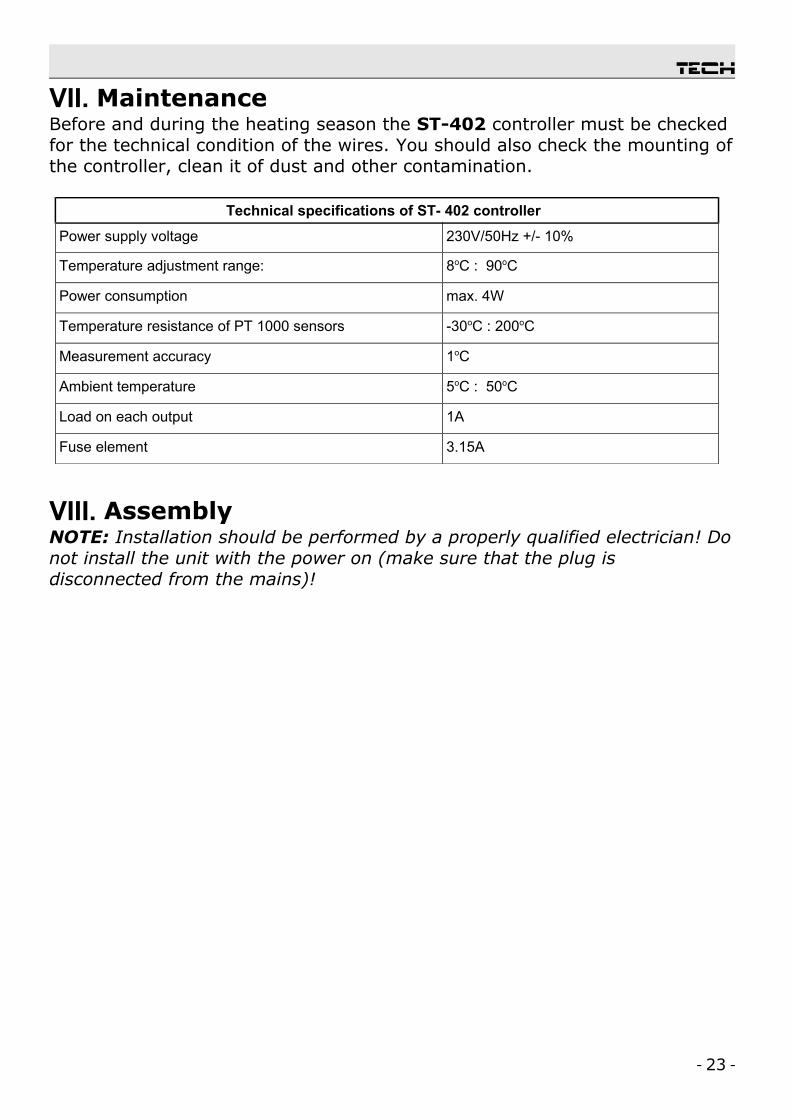
VII. MaintenanceBefore and during the heating season the ST-402 controller must be checked for the technical condition of the wires. You should also check the mounting of the controller, clean it of dust and other contamination.
Technical specifications of ST- 402 controller
Power supply voltage 230V/50Hz +/- 10%
Temperature adjustment range: 8oC : 90oC
Power consumption max. 4W
Temperature resistance of PT 1000 sensors -30oC : 200oC
Measurement accuracy 1oC
Ambient temperature 5oC : 50oC
Load on each output 1A
Fuse element 3.15A
VIII. AssemblyNOTE: Installation should be performed by a properly qualified electrician! Do not install the unit with the power on (make sure that the plug is disconnected from the mains)!
- 23 -

ST – 402N user's manual
Collector Installation Block Diagram
- 24 -

tech
Table of Contents
I. Intended Use......................................................................................5II. Principle of Operation.........................................................................4III. User’s Menu.....................................................................................5
III. a) Main Page.................................................................................5III. b) Operation Mode.........................................................................6III. c) Preset temperature....................................................................7III. d) Heating up - off.........................................................................7III. e) Peripherals................................................................................7III. f) Clock........................................................................................8III. g) Backlight..................................................................................8III. h) Language Version......................................................................8III. i) Alarm sound..............................................................................8III. j) Information...............................................................................8III. k) Service settings.........................................................................8
IV. Service Menu....................................................................................8IV. a) Installation diagram....................................................................8
IV. a.1) Diagram 1/11......................................................................9IV. a.2) Diagram 2/11......................................................................9IV. a.3) Diagram 3/11......................................................................9IV. a.4) Diagram 4/11....................................................................10IV. a.5) Diagram 5/11....................................................................10IV. a.6) Diagram 6/11....................................................................11IV. a.7) Diagram 7/11....................................................................11IV. a.8) Diagram 8/11....................................................................12IV. a.9) Diagram 9/11....................................................................13IV. a.10) Diagram 10/11.................................................................14IV. a.11) Diagram 11/11.................................................................14
IV. b) Accumulator tank.....................................................................15IV. b.1) Set-point temperature.........................................................15IV. b.2) Maximum temperature........................................................15IV. b.3)Tank hysteresis...................................................................15IV. b.3)Cooling down to set-point temperature...................................15
IV. c) Pumps.....................................................................................15IV. c.1) Adjustable or fixed pump speed............................................15IV. c.2) Maximum temperature of collector........................................15IV. c.3)Delta value for activation of solar pump..................................16IV. c.4) Delta value for deactivation of solar pump..............................16IV. c.5) Delta value for maximum speed............................................16IV. c.6) Temperature at which speed control is disabled.......................16
- 25 -

ST – 402N user's manualIV. c.7)Minimum operating speed for solar pump................................16IV. c.8) Maximum operating speed of solar pump...............................16IV. c.9) Transmission coefficient.......................................................16IV. c.10) Circuit sampling – activation threshold.................................16IV. c.11) Circuit Sampling...............................................................17
IV. d) Peripherals..............................................................................17IV. d.1) Circulation Pump ...............................................................17IV. d.2) PLT (Pellet) Boiler Fire-Up....................................................17IV. d.3) Heater..............................................................................19IV. d.4) Cooling with hot water pump................................................19IV. d.5) Contact (not) in the same setting as the pump.......................19IV. d.6) Temperature threshold output..............................................19
IV. g) Service menu...........................................................................19IV. h) Settings..................................................................................19IV. i) About......................................................................................19
V. Security..........................................................................................19VI. Maintenance...................................................................................20VIII. Assembly.....................................................................................21
- 26 -

tech
We are committed to protecting the environment. Manufacturing electronic devices imposes an obligation of providing for environmentally safe disposal of used electronic components and devices. Hence, we have been entered into a register kept by the Inspection For Environmental Protection. The crossed-out bin symbol on a product means that the product may not be disposed of to household waste containers. Recycling of wastes helps to protect the environment. The user is obliged to transfer their used equipment to a collection point where all electric and electronic components will be recycled.
- 27 -

ST – 402N user's manual
- 28 -