teaching technique used edibon scada system · computer controlled. wind energy unit, ... eeec....
TRANSCRIPT

1
Engineering and Technical Teaching Equipment
ISO 9001: Quality Management (for Design, Manufacturing, Commercialization
and After-sales service)
European Union Certificate (total safety)
Certificates ISO 14001 and ECO-Management and Audit Scheme
(environmental management)
Certificate and Worlddidac Member
http://www.youtube.com/embed/CEgMr00oBPwhttp://www.edibon.com/products/catalogues/en/keyfeatures.pdf
Computer Controlled Wind Energy Unit,with SCADA
EEEC
Key features: h Advanced Real-Time SCADA. h Open Control + Multicontrol + Real-Time Control. h Specialized EDIBON Control Software based on LabVIEW. h National Instruments Data Acquisition board (250 KS/s, kilo samples per second). h Calibration exercises, which are included, teach the user how to calibrate a
sensor and the importance of checking the accuracy of the sensors before taking measurements.
h Projector and/or electronic whiteboard compatibility allows the unit to be explained and demonstrated to an entire class at one time.
h Capable of doing applied research, real industrial simulation, training courses, etc.
h Remote operation and control by the user and remote control for EDIBON technical support, are always included.
h Totally safe, utilizing 4 safety systems (Mechanical, Electrical, Electronic & Software).
h Designed and manufactured under several quality standards. h Optional ICAI software to create, edit and carry out practical exercises, tests,
exams, calculations, etc. Apart from monitoring user's knowledge and progress reached.
h This unit has been designed for future expansion and integration. A common expansion is the EDIBON Scada-Net (ESN) System which enables multiple students to simultaneously operate many units in a network.
For more information about Key Features, click here
Computer (not included in
the supply)
EDIBON SCADA System
Control Interface Box
Data Acquisition
Board
Software for: - Computer Control - Data Acquisition - Data Management
Cables and Accessories
ManualsUnit: EEEC. Computer Controlled Wind Energy Unit
* Minimum supply always includes: 1 + 2 + 3 + 4 + 5 + 6 (Computer not included in the supply)
Teaching Technique
used
2
5
6
3 4
1

www.edibon.com2
Wind energy is a renewable source of energy that occurs in the nature spontaneously and can be harnessed to meet the necessity of power. It is being used from a very early age and the technology of using this energy efficiently is being improved with time.
Wind power is the conversion of wind energy into a useful form of energy. It is done using wind turbines to make electricity, wind mills for mechanical power, wind pumps for pumping water or drainage, or sails to propel ships.
The Computer Controlled Wind Energy Unit, “EEEC”, contains an aerogenerator, in laboratory-scale, and is used to study the conversion of kinetic wind energy into electrical energy and to study the influence of some factors on this generation.
The unit consists of a stainless steel tunnel, an aerogenerator and an axial fan with variable speed (computer controlled). A rotor (or turbine) to place up to blades and a generator are the core elements of the aerogenerator.
The air speed is varied by changing the rotational speed of the axial fan. This fan generates the air flow required to set the rotor of the wind energy unit.
The generator converts the rotor's kinetic energy into electrical energy.
The aerogenerator incidence angle and the angle of every blade can be modified. The blades can be removable and it's possible to set different blade configurations.
This unit includes a DC Load Regulator, an auxiliary battery charger, a battery and a DC Loads module. The DC Loads module contains DC lamps, rheostat, DC motor, load selector and switches to select the type of load.
The following parameters are measured: air temperature, air speed, speed of the rotor and voltage and current. There is a temperature sensor before the rotor of the aerogenerator. The air speed is measured with a sensor placed in the tunnel and also is determined the rotational speed of the aerogenerator (r.p.m.). A voltage and current sensor allows to measure the voltage and current to determine the power.
It is possible to know, in real time, the value of the DC voltage and the current given by aerogenerator, measured before and after the regulator.
This Computer Controlled Unit is supplied with the EDIBON Computer Control System (SCADA), and includes: The unit itself + a Control Interface Box + a Data Acquisition Board + Computer Control, Data Acquisition and Data Management Software Packages, for controlling the process and all parameters involved in the process.
INTRODUCTION
GENERAL DESCRIPTION
PROCESS DIAGRAM AND UNIT ELEMENTS ALLOCATION
EEEC detail

www.edibon.com3
Process diagram and unit elements allocation
Aerogenerator configurations
Aerogenerator with six blades Aerogenerator with three blades Aerogenerator with two blades
Tunnel
Axial fan for wind simulator
AerogeneradorDC Load Regulator
DC Loads Module
Single-phase Inverter(optional EE-KIT)
AC Loads Module (optional EE-KIT)
Battery
Axial fan(optional EE-KIT)
Lamps (optional EE-KIT)
Auxiliary battery charger

www.edibon.com4
EEEC. Unit:Unit mounted on an anodized aluminum structure and panels of painted steel.Main metallic elements of stainless steel.Diagram in the front panel with similar distribution to the elements in the real unit.The unit includes:
Stainless steel tunnel of 2000 x 550 x 550 mm approx. (78.74 x 21.65 x 21.65 inches approx.), which includes two transparent windows of 1000 x 130 mm approx. (39.37 x 5.11 inches approx.).
Aerogenerator:Diameter: 510 mm. Starting air speed: 2.0 m/s.
Max. power output: 60 W. Voltage: 12 V. Max. charging current: 5 A. It includes a set of six blades.
The aerogenerator incidence angle can be modified to simulate different weather conditions and it's possible to set different blade configurations (aerogenerator with six, three or two blades).This unit allows to change the angle of every blade, as each one embeds its own calibrated protractor. The blades can be adjusted in a 360º range.Low friction alternator, which provides a smooth and silent output.
Friction less alternator and fixed shaft.Axial fan with variable speed (computer controlled) for wind simulation:
Max. flow rate: 10650 m³/h. Max. power: 1.5 kW. It includes a finger guard. DC Load Regulator:
It regulates how power generated in the aerogenerator is distributed to and from the auxiliary battery and to the load. A display informs about the state of the charge, operating parameters and fault messages. The functions of the electronic protection are:
Overvoltage disconnection, short circuit protection of load and module, overvoltage protection at module input, over-temperature and overload protection, and battery overvoltage shutdown.
Auxiliary battery charger: It carefully assesses the battery and then delivers the optimum charge required. Battery: Nominal voltage: 12 V. Rated capacity (20 hours rate): 24 A/H. DC Loads Module: Metallic box with diagram in the front panel. Two lamps of 12 V. One DC motor: voltage: 24 V, power: 5 W. Rheostat of 500 W. Two manual switches. Independent connection for every load with the help of the four position load selector: Position 1: The aerogenerator or regulator operates at open circuit voltage.
Position 2: The DC lamps and the rheostat are directly connected to the aerogenerator or regulator, depending on the selection made in the computer. These loads can be connected independently or in parallel with the help of manual switches.
Position 3: The DC motor is directly connected to the aerogenerator or regulator. Position 4: Bypass mode, there are no DC loads. Sensors: “J” type temperature sensor to measure the air temperature inside of the tunnel. The air speed is measured with a sensor placed in the tunnel; sensor range: 0.20 – 10 m/s. An optical sensor measures the rotational speed of the aerogenerator (r.p.m.).
DC voltage and current sensor. It is possible to know, in real time, the value of the DC voltage and the current given by aerogenerator, measured before and after the regulator.
The complete unit includes as well:
COMPLETE TECHNICAL SPECIFICATIONS (for main items)
With this unit there are several options and possibilities: - Main items: 1, 2, 3, 4, 5 and 6. - Optional items: 7, 8, 9, 10 and 11.Let us describe first the main items (1 to 6):1
Advanced Real-Time SCADA.Open Control + Multicontrol + Real-Time Control.Specialized EDIBON Control Software based on LabVIEW.National Instruments Data Acquisition board (250 KS/s, kilo samples per second).Calibration exercises, which are included, teach the user how to calibrate a sensor and the importance of checking the accuracy of the sensors before taking measurements.Projector and/or electronic whiteboard compatibility allows the unit to be explained and demonstrated to an entire class at one time.Capable of doing applied research, real industrial simulation, training courses, etc.Remote operation and control by the user and remote control for EDIBON technical support, are always included.Totally safe, utilizing 4 safety systems (Mechanical, Electrical, Electronic & Software).Designed and manufactured under several quality standards.Optional ICAI software to create, edit and carry out practical exercises, tests, exams, calculations, etc. Apart from monitoring user's knowledge and progress reached.This unit has been designed for future expansion and integration. A common expansion is the EDIBON Scada-Net (ESN) System which enables multiple students to simultaneously operate many units in a network.
Unit: EEEC

www.edibon.com5
DAB. Data Acquisition Board: The Data Acquisition board is part of the SCADA system. PCI Express Data acquisition board (National Instruments) to be placed in a computer slot. Bus PCI Express. Analog input: Number of channels= 16 single-ended or 8 differential. Resolution=16 bits, 1 in 65536. Sampling rate up to: 250 KS/s (kilo samples per second). Input range (V)=±10 V. Data transfers=DMA, interrupts, programmed I/0. DMA channels=6. Analog output: Number of channels=2. Resolution=16 bits, 1 in 65536. Maximum output rate up to: 900 KS/s. Output range(V)=±10 V. Data transfers=DMA, interrupts, programmed I/0. Digital Input/Output: Number of channels=24 inputs/outputs. D0 or DI Sample Clock frequency: 0 to 100 MHz. Timing: Number of Counter/timers=4. Resolution: Counter/timers: 32 bits. EEEC/CCSOF. Computer Control + Data Acquisition + Data Management Software: The three softwares are part of the SCADA system. Compatible with actual Windows operating systems. Graphic and intuitive simulation of the process in screen. Compatible with the industry standards. Registration and visualization of all process variables in an automatic and simultaneous way. Flexible, open and multicontrol software, developed with actual windows graphic systems, acting simultaneously on all process parameters. Management, processing, comparison and storage of data. Sampling velocity up to 250 KS/s (kilo samples per second). Calibration system for the sensors involved in the process. It allows the registration of the alarms state and the graphic representation in real time. Comparative analysis of the obtained data, after the process and modification of the conditions during the process. Open software, allowing the teacher to modify texts, instructions. Teacher’s and student’s passwords to facilitate the teacher’s control on the student, and allowing the access to different work levels. This unit allows the 30 students of the classroom to visualize simultaneously all the results and the manipulation of the unit, during the process, by using a projector or an electronic whiteboard.Cables and Accessories, for normal operation.Manuals: This unit is supplied with 8 manuals: Required Services, Assembly and Installation, Interface and Control Software, Starting-up, Safety, Maintenance, Calibration & Practices Manuals.
References 1 to 6 are the main items: EEEC + EEEC/CIB + DAB + EEEC/CCSOF + Cables and Accessories + Manuals are included in the minimum supply for enabling normal and full operation.
EEEC/CIB. Control Interface Box: The Control Interface Box is part of the SCADA system. Control interface box with process diagram in the front panel and with the same distribution that the different elements located in the unit, for an easy understanding by the student. All sensors, with their respective signals, are properly manipulated from -10V. to +10V. computer output. Sensors connectors in the interface have different pines numbers (from 2 to 16), to avoid connection errors. Single cable between the control interface box and computer. The unit control elements are permanently computer controlled, without necessity of changes or connections during the whole process test procedure. Simultaneous visualization in the computer of all parameters involved in the process. Calibration of all sensors involved in the process. Real time curves representation about system responses. Storage of all the process data and results in a file. Graphic representation, in real time, of all the process/system responses. All the actuators’ values can be changed at any time from the keyboard allowing the analysis about curves and responses of the whole process. All the actuators and sensors values and their responses are displayed on only one screen in the computer. Shield and filtered signals to avoid external interferences. Real time computer control with flexibility of modifications from the computer keyboard of the parameters, at any moment during the process. Real time computer control for pumps, compressors, heating elements, control valves, etc. Real time computer control for parameters involved in the process simultaneously. Open control allowing modifications, at any moment and in real time, of parameters involved in the process simultaneously. Three safety levels, one mechanical in the unit, another electronic in the control interface and the third one in the control software.
DAB
EEEC/CCSOF
EEEC/CIB
*
4
5
6
3
Complete Technical Specifications (for main items)
Optional Models and Accessories: (Not included) (See in page 6) - EE-KIT. Kit of Conversion and Consumption Simulation (AC): Single-phase inverter. AC Loads Module: Three lamps, an axial compact fan with plastic guards and four positions selector. AC voltage and current sensor. - EE-KIT2. Grid Connection Inverter Kit: Grid Connection Inverter. Grid Simulator (ESR).
www.edibon.com6
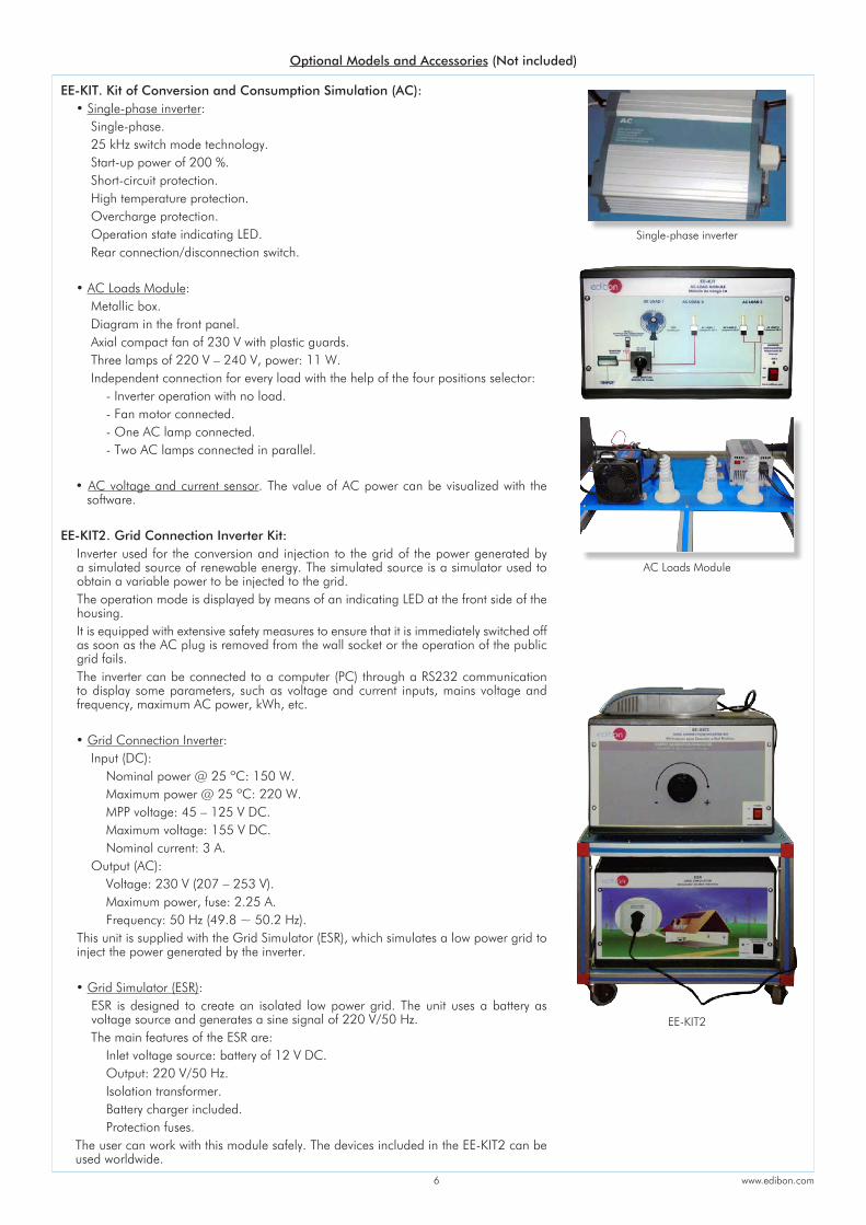
EE-KIT. Kit of Conversion and Consumption Simulation (AC): • Single-phase inverter: Single-phase. 25 kHz switch mode technology. Start-up power of 200 %. Short-circuit protection. High temperature protection. Overcharge protection. Operation state indicating LED. Rear connection/disconnection switch. • AC Loads Module: Metallic box. Diagram in the front panel. Axial compact fan of 230 V with plastic guards. Three lamps of 220 V – 240 V, power: 11 W. Independent connection for every load with the help of the four positions selector: - Inverter operation with no load. - Fan motor connected. - One AC lamp connected. - Two AC lamps connected in parallel.
• AC voltage and current sensor. The value of AC power can be visualized with the software.
EE-KIT2. Grid Connection Inverter Kit:
Inverter used for the conversion and injection to the grid of the power generated by a simulated source of renewable energy. The simulated source is a simulator used to obtain a variable power to be injected to the grid.The operation mode is displayed by means of an indicating LED at the front side of the housing.It is equipped with extensive safety measures to ensure that it is immediately switched off as soon as the AC plug is removed from the wall socket or the operation of the public grid fails.The inverter can be connected to a computer (PC) through a RS232 communication to display some parameters, such as voltage and current inputs, mains voltage and frequency, maximum AC power, kWh, etc.
• Grid Connection Inverter: Input (DC): Nominal power @ 25 ºC: 150 W. Maximum power @ 25 ºC: 220 W. MPP voltage: 45 – 125 V DC. Maximum voltage: 155 V DC. Nominal current: 3 A. Output (AC): Voltage: 230 V (207 – 253 V). Maximum power, fuse: 2.25 A. Frequency: 50 Hz (49.8 ~ 50.2 Hz).
This unit is supplied with the Grid Simulator (ESR), which simulates a low power grid to inject the power generated by the inverter.
• Grid Simulator (ESR):ESR is designed to create an isolated low power grid. The unit uses a battery as voltage source and generates a sine signal of 220 V/50 Hz.
The main features of the ESR are: Inlet voltage source: battery of 12 V DC. Output: 220 V/50 Hz. Isolation transformer. Battery charger included. Protection fuses.
The user can work with this module safely. The devices included in the EE-KIT2 can be used worldwide.
Optional Models and Accessories (Not included)
Single-phase inverter
EE-KIT2
AC Loads Module

www.edibon.com7
1.- Identification and familiarization with all components of the unit and how they are associated with its operation.
2.- Familiarization with the regulator parameters and the wind energy measurements.
3.- Study of the conversion of kinetic wind energy into electrical energy.
4.- Study of the power generated by the aerogenerator depending on the wind speed.
5.- Determination of the typical parameters of the aerogenerator (short circuit current, open-circuit voltage, maximum power).
6.- Determination of the I-V curve.7.- Study of voltage, current and power in function of different loads.8.- Study of the influence of the load variation on the aerogenerator.9.- Determination of the maximum power output of the aerogenerator.10.-Determination of the P-air speed curve.11.-Study of the power generated by the aerogenerator depending
on the incident angle of the air.12.-Study of the characteristic curve of the rotor.13.-Study of the connection of loads to direct voltage.Additional practical possibilities:14.-Sensors calibration.15.-Study of the power coefficient.16.-Study of the aerogenerator operation in function of the blade
configurations (aerogenerator with six, three or two blades).17.-Study of the optimum number of blades.18.-Study of the aerogenerator operation in function of the angle of
the blades.19.-Study of the efficiency of a wind power unit.
20.-Determination of the efficiency of a wind power unit in function of the number of blades, angle of the blades and angle of the generator.
Practices to be done with the OPTIONAL KIT “EE-KIT”:21.-Study of the connection of loads to alternating voltage of 220 V.Practices to be done with the OPTIONAL KIT “EE-KIT2”:22.-Study of the inverter connected to the grid simulator.Other possibilities to be done with this Unit:23.-Many students view results simultaneously. To view all results in real time in the classroom by means of a
projector or an electronic whiteboard.24.-Open Control, Multicontrol and Real Time Control.
This unit allows intrinsically and/or extrinsically to change the span, gains; proportional, integral, derivative parameters; etc, in real time.
25.-The Computer Control System with SCADA allows a real industrial simulation.
26.-This unit is totally safe as uses mechanical, electrical and electronic, and software safety devices.
27.-This unit can be used for doing applied research.28.-This unit can be used for giving training courses to Industries even
to other Technical Education Institutions.29.-Control of the EEEC unit process through the control interface
box without the computer.30.-Visualization of all the sensors values used in the EEEC unit
process.- By using PLC-PI additional 19 more exercises can be done.- Several other exercises can be done and designed by the user.
EEEC: Unit: -Dimensions: 2300 x 630 x 1080 mm approx. (90.55 x 24.80 x 42.52 inches approx.)
-Weight: 120 Kg approx. (264.55 pounds approx.)
Control Interface Box: -Dimensions: 490 x 330 x 310 mm approx. (19.29 x 12.99 x 12.20 inches approx.)
-Weight: 10 Kg approx. (22 pounds approx.)
DIMENSIONS AND WEIGHTS
EXERCISES AND PRACTICAL POSSIBILITIES TO BE DONE WITH THE MAIN ITEMS
AVAILABLE VERSIONS
Offered in this catalogue:
- EEEC. Computer Controlled Wind Energy Unit.
Offered in other catalogues:
- EEE. Wind Energy Unit.
- MINI-EEEC. Computer Controlled Wind Energy Basic Unit.
- MINI-EEE. Wind Energy Basic Unit.
- Electrical supply: single-phase, 220 V/50 Hz or 110 V/60 Hz.
- Computer.
REQUIRED SERVICES
OPTIONAL MODELS AND ACCESSORIES (Not included)
- EE-KIT. Kit of Conversion and Consumption Simulation (AC).
- EE-KIT2. Grid Connection Inverter Kit.

www.edibon.com8
SOFTWARE MAIN SCREENS
SCADAMain screen
The teacher and the students can calibrate the unit with a password provided by EDIBON. The teacher can restore the factory calibration any time.
Software for Sensors CalibrationExample of screens
Main software operation possibilities.
Sensors displays, real time values, and extra output parameters. Sensors: ST=Temperature sensor. SVA=Air speed sensor. SV=Speed sensor (aerogenerator). DC Load Module: I_DC=Current sensor. V_DC=Voltage sensor.
Actuators controls. Actuators: AVE= Fan.
Channel selection and other plot parameters.
Real time graphics displays.
I
II
III
IV
V
I
II
III
IVV

www.edibon.com9
SOME REAL RESULTS OBTAINED FROM THIS UNIT
Signal versus signal chart when any of the measured and calculated variables can be represented.
Signal versus signal chart when any of the measured and calculated variables can be represented.
Signal versus signal chart when any of the measured and calculated variables can be represented.
Representation in real time of the measured and calculated magnitudes.

www.edibon.com10
COMPLETE TECHNICAL SPECIFICATIONS (for optional items)
Additionally to the main items (1 to 6) described, we can offer, as optional, other items from 7 to 11.All these items try to give more possibilities for: a) Industrial configuration. (PLC) b) Technical and Vocational Education configuration. (ICAI and FSS) c) Multipost Expansions options. (Mini ESN and ESN)
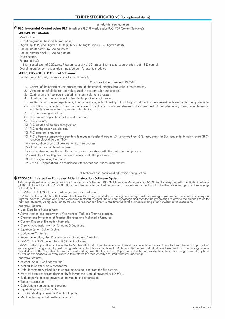
a) Industrial configurationPLC. Industrial Control using PLC (it includes PLC-PI Module plus PLC-SOF Control Software):-PLC-PI. PLC Module:Metallic box.Circuit diagram in the module front panel.Front panel: Digital inputs (X) and Digital outputs (Y) block: 16 Digital inputs, activated by switches and 16 LEDs for confirmation (red). 14 Digital outputs (through SCSI connector) with 14 LEDs for message (green). Analog inputs block: 16 Analog inputs (-10 V. to + 10 V.) (through SCSI connector). Analog outputs block: 4 Analog outputs (-10 V. to + 10 V.) (through SCSI connector). Touch screen: High visibility and multiple functions. Display of a highly visible status. Recipe function. Bar graph function. Flow display function. Alarm list. Multi language function. True type fonts.Back panel: Power supply connector. Fuse 2A. RS-232 connector to PC. USB 2.0 connector to PC.Inside: Power supply outputs: 24 Vdc, 12 Vdc, -12 Vdc, 12 Vdc variable. Panasonic PLC: High-speed scan of 0.32 µsec. for a basic instruction. Program capacity of 32 Ksteps, with a sufficient comment area. Power supply input (100 to 240 V AC). DC input: 16 (24 V DC). Relay output: 14. High-speed counter. Multi-point PID control. Digital inputs/outputs and analog inputs/outputs Panasonic modules.Communication RS232 wire to computer (PC).Dimensions: 490 x 330 x 310 mm. approx. (19.29 x 12.99 x 12.20 inches approx.). Weight: 30 Kg. approx. (66 pounds approx.). -EEEC/PLC-SOF. PLC Control Software:For this particular unit, always included with PLC supply.The software has been designed using Labview and it follows the unit operation procedure and linked with the Control Interface Box used in the Computer Controlled Wind Energy Unit (EEEC).
1.- Control of the particular unit process through the control interface box without the computer.
2.- Visualization of all the sensors values used in the particular unit process. 3.- Calibration of all sensors included in the particular unit process. 4.- Hand on of all the actuators involved in the particular unit process. 5.- Realization of different experiments, in automatic way, without having in
front the particular unit. (These experiments can be decided previously). 6.- Simulation of outside actions, in the cases do not exist hardware
elements. (Example: test of complementary tanks, complementary industrialenvironment to the process to be studied, etc).
7.- PLC hardware general use. 8.- PLC process application for the particular unit. 9.- PLC structure. 10.-PLC inputs and outputs configuration. 11.-PLC configuration possibilities. 12.-PLC program languages.
13.-PLC different programming standard languages (ladder diagram (LD), structured text (ST), instructions list (IL), sequential function chart (SFC), function block diagram (FBD)).
14.-New configuration and development of new process. 15.-Hand on an established process. 16.-To visualize and see the results and to make comparisons with the
particular unit process. 17.-Possibility of creating new process in relation with the particular unit. 18.-PLC Programming Exercises. 19.-Own PLC applications in accordance with teacher and student
requirements.
Practices to be done with PLC-PI:
PLC-PI. PLC Module
PLC CONTROL PLC-SOF. Control Software
7
Control Interface Box
Data Acquisition
Board
Software for: - Computer Control - Data Acquisition - Data Management
Unit

www.edibon.com11
Complete Technical Specifications (for optional items)
Instructor Software
Student Software
ETTE. EDIBON Training Test & Exam Program Package - Main Screen with Numeric Result
Question
ERS. EDIBON Results & Statistics Program Package - Question
Explanation
ERS. EDIBON Results & Statistics Program Package - Student
Scores Histogram
ECAL. EDIBON Calculations Program Package Main Screen
ECAL. EDIBON Calculations Program Package - Formula Editor Screen
EPE. EDIBON Practical Exercise Program Package Main Screen
For more information see ICAI catalogue. Click on the following link:
www.edibon.com/en/files/expansion/ICAI/catalog
b) Technical and Vocational Education configuration
EEEC/ICAI. Interactive Computer Aided Instruction Software System.This complete software package consists of an Instructor Software (EDIBON Classroom Manager - ECM-SOF) totally integrated with the Student Software (EDIBON Student Labsoft - ESL-SOF). Both are interconnected so that the teacher knows at any moment what is the theoretical and practical knowledge of the students.
This software is optional and can be used additionally to items (1 to 6).
- ECM-SOF. EDIBON Classroom Manager (Instructor Software).
ECM-SOF is the application that allows the Instructor to register students, manage and assign tasks for workgroups, create own content to carry out Practical Exercises, choose one of the evaluation methods to check the Student knowledge and monitor the progression related to the planned tasks for individual students, workgroups, units, etc... so the teacher can know in real time the level of understanding of any student in the classroom.
ECM-SOF. EDIBON Classroom Manager (Instructor Software)
Application Main Screen
ESL-SOF. EDIBON Student LabSoft (Student Software) Application Main Screen
8
- ESL-SOF. EDIBON Student Labsoft (Student Software).
ESL-SOF is the application addressed to the Students that helps them to understand theoretical concepts by means of practical exercises and to prove their knowledge and progression by performing tests and calculations in addition to Multimedia Resources. Default planned tasks and an Open workgroup are provided by EDIBON to allow the students start working from the first session. Reports and statistics are available to know their progression at any time, as well as explanations for every exercise to reinforce the theoretically acquired technical knowledge.
Innovative features:
• User Data Base Management.
• Administration and assignment of Workgroup, Task and Training sessions.
• Creation and Integration of Practical Exercises and Multimedia Resources.
• Custom Design of Evaluation Methods.
• Creation and assignment of Formulas & Equations.
• Equation System Solver Engine.
• Updatable Contents.
• Report generation, User Progression Monitoring and Statistics.
Innovative features:
• Student Log-In & Self-Registration.
• Existing Tasks checking & Monitoring.
• Default contents & scheduled tasks available to be used from the first session.
• Practical Exercises accomplishment by following the Manual provided by EDIBON.
• Evaluation Methods to prove your knowledge and progression.
• Test self-correction.
• Calculations computing and plotting.
• Equation System Solver Engine.
• User Monitoring Learning & Printable Reports.
• Multimedia-Supported auxiliary resources.

www.edibon.com12
Mini ESN. EDIBON Mini Scada-Net System. Mini ESN. EDIBON Mini Scada-Net System allows up to 30 students to work with a Teaching Unit in any laboratory, simultaneously. It is useful for both, Higher Education and/or Technical and Vocational Education. The Mini ESN system consists of the adaptation of any EDIBON Computer Controlled Unit with SCADA integrated in a local network. This system allows to view/control the unit remotely, from any computer integrated in the local net (in the classroom), through the main computer connected to the unit. Then, the number of possible users who can work with the same unit is higher than in an usual way of working (usually only one). Main characteristics: - It allows up to 30 students to work simultaneously with the EDIBON Computer Controlled Unit with SCADA, connected in a local net. - Open Control + Multicontrol + Real Time Control + Multi Student Post. - Instructor controls and explains to all students at the same time. - Any user/student can work doing "real time" control/multicontrol and visualisation. - Instructor can see in the computer what any user/student is doing in the unit. - Continuous communication between the instructor and all the users/students connected. Main advantages: - It allows an easier and quicker understanding. - This system allows you can save time and cost. - Future expansions with more EDIBON Units.
c) Multipost Expansions options
For more information see Mini ESN catalogue. Click on the following link:
www.edibon.com/products/catalogues/en/Mini-ESN.pdf
Mini ESN.EDIBON Mini Scada-Net System
ESN. EDIBON Scada-Net System.
This unit can be integrated, in the future, into a Complete Laboratory with many Units and many Students.
For more information see ESN catalogue. Click on the following link:
www.edibon.com/products/catalogues/en/units/energy/esn-alternativeenergies/ESN-ALTERNATIVE_ENERGIES.pdf
Mini Scada-Net Software
Note: The Mini ESN system can be used with any EDIBON computer controlled unit
Computer Controlled Wind Energy Unit (EEEC)
1 UNIT= up to 30 STUDENTS can work
simultaneously
10
11
Software for: - Computer Control - Data Acquisition - Data Management
Control Interface Box
Instructors' Central
Computer
LOCAL NET FOR 30 STUDENTS
Complete Technical Specifications (for optional items)
Example of some screens
For more information see FSS catalogue. Click on the following link:
www.edibon.com/en/files/expansion/FSS/catalog
EEEC/FSS. Faults Simulation System. Faults Simulation System (FSS) is a Software package that simulates several faults in any EDIBON Computer Controlled Unit. It is useful for Technical and Vocational level.The “FAULTS” mode consists in causing several faults in the unit normal operation. The student must find them and solve them. There are several kinds of faults that can be grouped in the following sections: Faults affecting the sensors measurement: - An incorrect calibration is applied to them. - Non-linearity. Faults affecting the actuators: - Actuators channels interchange at any time during the program
execution. - Response reduction of an actuator. Faults in the controls execution: - Inversion of the performance in ON/OFF controls. - Reduction or increase of the calculated total response. - The action of some controls is annulled. On/off faults: - Several on/off faults can be included.
9

www.edibon.com13
ORDER INFORMATION
1
2
3
4
5
6
Main items (always included in the supply)
Minimum supply always includes:
Unit: EEEC. Computer Controlled Wind Energy Unit.
EEEC/CIB. Control Interface Box.
DAB. Data Acquisition Board.
EEEC/CCSOF. Computer Control + Data Acquisition + Data Management Software.
Cables and Accessories, for normal operation.
Manuals.
*IMPORTANT: Under EEEC we always supply all the elements for immediate running as 1, 2, 3, 4, 5 and 6.
Optional items (supplied under specific order)
a) Industrial configuration
PLC. Industrial Control using PLC (it includes PLC-PI Module plus PLC-SOF Control Software):
- PCL-PI. PLC Module.
- EEEC/PLC-SOF. PLC Control Software.
b) Technical and Vocational Education configuration
EEEC/ICAI. Interactive Computer Aided Instruction Software System.
EEEC/FSS. Faults Simulation System.
c) Multipost Expansions options
Mini ESN. EDIBON Mini Scada-Net System.
ESN. EDIBON Scada-Net System.
7
8
9
10
11

www.edibon.com14
TENDER SPECIFICATIONS (for main items)
EEEC. Unit:Unit mounted on an anodized aluminum structure and panels of painted steel.Main metallic elements of stainless steel.Diagram in the front panel with similar distribution to the elements in the real unit.The unit includes:
Stainless steel tunnel of 2000 x 550 x 550 mm approx. (78.74 x 21.65 x 21.65 inches approx.), which includes two transparent windows of 1000 x 130 mm approx. (39.37 x 5.11 inches approx.).
Aerogenerator: Diameter: 510 mm. Starting air speed: 2.0 m/s. Max. power output: 60 W. Voltage: 12 V. Max. charging current: 5 A. It includes a set of six blades.
The aerogenerator incidence angle can be modified to simulate different weather conditions and it's possible to set different blade configurations (aerogenerator with six, three or two blades).
This unit allows to change the angle of every blade, as each one embeds its own calibrated protractor. The blades can be adjusted in a 360º range. Low friction alternator, which provides a smooth and silent output. Friction less alternator and fixed shaft. Axial fan with variable speed (computer controlled) for wind simulation: Max. flow rate: 10650 m³/h. Max. power: 1.5 kW. It includes a finger guard. DC Load Regulator:
It regulates how power generated in the aerogenerator is distributed to and from the auxiliary battery and to the load. A display informs about the state of the charge, operating parameters and fault messages. The functions of the electronic protection are:
Overvoltage disconnection, short circuit protection of load and module, overvoltage protection at module input, over-temperature and overload protection, and battery overvoltage shutdown.
Auxiliary battery charger: It carefully assesses the battery and then delivers the optimum charge required. Battery: Nominal voltage: 12 V. Rated capacity (20 hours rate): 24 A/H. DC Loads Module: Metallic box with diagram in the front panel. Two lamps of 12 V. One DC motor: voltage: 24 V, power: 5 W. Rheostat of 500 W. Two manual switches. Independent connection for every load with the help of the four position load selector: Position 1: The aerogenerator or regulator operates at open circuit voltage.
Position 2: The DC lamps and the rheostat are directly connected to the aerogenerator or regulator, depending on the selection made in the computer. These loads can be connected independently or in parallel with the help of manual switches.
Position 3: The DC motor is directly connected to the aerogenerator or regulator. Position 4: Bypass mode, there are no DC loads. Sensors: “J” type temperature sensor to measure the air temperature inside of the tunnel. The air speed is measured with a sensor placed in the tunnel; sensor range: 0.20 – 10 m/s. An optical sensor measures the rotational speed of the aerogenerator (r.p.m.).
DC voltage and current sensor. It is possible to know, in real time, the value of the DC voltage and the current given by aerogenerator, measured before and after the regulator.
The complete unit includes as well:
EEEC/CIB. Control Interface Box:The Control Interface Box is part of the SCADA system.Control interface box with process diagram in the front panel.The unit control elements are permanently computer controlled.Simultaneous visualization in the computer of all parameters involved in the process.Calibration of all sensors involved in the process.Real time curves representation about system responses.All the actuators’ values can be changed at any time from the keyboard allowing the analysis about curves and responses of the whole process.Shield and filtered signals to avoid external interferences.Real time computer control with flexibility of modifications from the computer keyboard of the parameters, at any moment during the process.Real time computer control for parameters involved in the process simultaneously.Open control allowing modifications, at any moment and in real time, of parameters involved in the process simultaneously.Three safety levels, one mechanical in the unit, another electronic in the control interface and the third one in the control software.DAB. Data Acquisition Board:The Data Acquisition board is part of the SCADA system.PCI Express Data acquisition board (National Instruments) to be placed in a computer slot.Analog input: Channels= 16 single-ended or 8 differential. Resolution=16 bits, 1 in 65536. Sampling rate up to: 250 KS/s (kilo samples per second).Analog output: Channels=2. Resolution=16 bits, 1 in 65536.Digital Input/Output: Channels=24 inputs/outputs. EEEC/CCSOF. Computer Control +Data Acquisition+Data Management Software:The three softwares are part of the SCADA system.Compatible with the industry standards.Flexible, open and multicontrol software, developed with actual windows graphic systems, acting simultaneously on all process parameters.Management, processing, comparison and storage of data.Sampling velocity up to 250 KS/s (kilo samples per second).Calibration system for the sensors involved in the process.It allows the registration of the alarms state and the graphic representation in real time.Open software, allowing the teacher to modify texts, instructions. Teacher’s and student’s passwords to facilitate the teacher’s control on the student, and allowing the access to different work levels.This unit allows the 30 students of the classroom to visualize simultaneously all the results and the manipulation of the unit, during the process, by using a projector or an electronic whiteboard.Cables and Accessories, for normal operation.Manuals: This unit is supplied with 8 manuals: Required Services, Assembly and Installation, Interface and Control Software, Starting-up, Safety, Maintenance, Calibration & Practices Manuals.
1
3
4
56
Advanced Real-Time SCADA.Open Control + Multicontrol + Real-Time Control.Specialized EDIBON Control Software based on LabVIEW.National Instruments Data Acquisition board (250 KS/s, kilo samples per second).Calibration exercises, which are included, teach the user how to calibrate a sensor and the importance of checking the accuracy of the sensors before taking measurements.Projector and/or electronic whiteboard compatibility allows the unit to be explained and demonstrated to an entire class at one time.Capable of doing applied research, real industrial simulation, training courses, etc.Remote operation and control by the user and remote control for EDIBON technical support, are always included.Totally safe, utilizing 4 safety systems (Mechanical, Electrical, Electronic & Software).Designed and manufactured under several quality standards.Optional ICAI software to create, edit and carry out practical exercises, tests, exams, calculations, etc. Apart from monitoring user's knowledge and progress reached.This unit has been designed for future expansion and integration. A common expansion is the EDIBON Scada-Net (ESN) System which enables multiple students to simultaneously operate many units in a network.
2
Optional Models and Accessories: (Not included) - EE-KIT. Kit of Conversion and Consumption Simulation (AC): Single-phase inverter. AC Loads Module: Three lamps, an axial compact fan with plastic guards and four positions selector. AC voltage and current sensor. - EE-KIT2. Grid Connection Inverter Kit: Grid Connection Inverter. Grid Simulator (ESR).

www.edibon.com15
Exercises and Practical Possibilities to be done with the Main Items
1.- Identification and familiarization with all components of the unit and how they are associated with its operation.
2.- Familiarization with the regulator parameters and the wind energy measurements.
3.- Study of the conversion of kinetic wind energy into electrical energy.
4.- Study of the power generated by the aerogenerator depending on the wind speed.
5.- Determination of the typical parameters of the aerogenerator (short circuit current, open-circuit voltage, maximum power).
6.- Determination of the I-V curve.
7.- Study of voltage, current and power in function of different loads.
8.- Study of the influence of the load variation on the aerogenerator.
9.- Determination of the maximum power output of the aerogenerator.
10.-Determination of the P-air speed curve.
11.-Study of the power generated by the aerogenerator depending on the incident angle of the air.
12.-Study of the characteristic curve of the rotor.
13.-Study of the connection of loads to direct voltage.
Additional practical possibilities:
14.-Sensors calibration.
15.-Study of the power coefficient.
16.-Study of the aerogenerator operation in function of the blade configurations (aerogenerator with six, three or two blades).
17.-Study of the optimum number of blades.
18.-Study of the aerogenerator operation in function of the angle of the blades.
19.-Study of the efficiency of a wind power unit.
20.-Determination of the efficiency of a wind power unit in function of the number of blades, angle of the blades and angle of the generator.
Practices to be done with the OPTIONAL KIT “EE-KIT”:
21.-Study of the connection of loads to alternating voltage of 220 V.
Practices to be done with the OPTIONAL KIT “EE-KIT2”:
22.-Study of the inverter connected to the grid simulator.
Other possibilities to be done with this Unit:
23.-Many students view results simultaneously.
To view all results in real time in the classroom by means of a projector or an electronic whiteboard.
24.-Open Control, Multicontrol and Real Time Control.
This unit allows intrinsically and/or extrinsically to change the span, gains; proportional, integral, derivative parameters; etc, in real time.
25.-The Computer Control System with SCADA allows a real industrial simulation.
26.-This unit is totally safe as uses mechanical, electrical and electronic, and software safety devices.
27.-This unit can be used for doing applied research.
28.-This unit can be used for giving training courses to Industries even to other Technical Education Institutions.
29.-Control of the EEEC unit process through the control interface box without the computer.
30.-Visualization of all the sensors values used in the EEEC unit process.
- By using PLC-PI additional 19 more exercises can be done.
- Several other exercises can be done and designed by the user.
Tender Specifications (for main items)
www.edibon.com16
TENDER SPECIFICATIONS (for optional items)
a) Industrial configuration
b) Technical and Vocational Education configuration
PLC. Industrial Control using PLC (it includes PLC-PI Module plus PLC-SOF Control Software):
-PLC-PI. PLC Module: Metallic box. Circuit diagram in the module front panel. Digital inputs (X) and Digital outputs (Y) block: 16 Digital inputs. 14 Digital outputs. Analog inputs block: 16 Analog inputs. Analog outputs block: 4 Analog outputs. Touch screen. Panasonic PLC: High-speed scan of 0.32 µsec. Program capacity of 32 Ksteps. High-speed counter. Multi-point PID control. Digital inputs/outputs and analog inputs/outputs Panasonic modules.
-EEEC/PLC-SOF. PLC Control Software: For this particular unit, always included with PLC supply.
EEEC/ICAI. Interactive Computer Aided Instruction Software System.This complete software package consists of an Instructor Software (EDIBON Classroom Manager - ECM-SOF) totally integrated with the Student Software (EDIBON Student Labsoft - ESL-SOF). Both are interconnected so that the teacher knows at any moment what is the theoretical and practical knowledge of the students.- ECM-SOF. EDIBON Classroom Manager (Instructor Software).ECM-SOF is the application that allows the Instructor to register students, manage and assign tasks for workgroups, create own content to carry out Practical Exercises, choose one of the evaluation methods to check the Student knowledge and monitor the progression related to the planned tasks for individual students, workgroups, units, etc...so the teacher can know in real time the level of understanding of any student in the classroom.Innovative features:• User Data Base Management.• Administration and assignment of Workgroup, Task and Training sessions.• Creation and Integration of Practical Exercises and Multimedia Resources.• Custom Design of Evaluation Methods.• Creation and assignment of Formulas & Equations.• Equation System Solver Engine.• Updatable Contents.• Report generation, User Progression Monitoring and Statistics.- ESL-SOF. EDIBON Student Labsoft (Student Software).ESL-SOF is the application addressed to the Students that helps them to understand theoretical concepts by means of practical exercises and to prove their knowledge and progression by performing tests and calculations in addition to Multimedia Resources. Default planned tasks and an Open workgroup are provided by EDIBON to allow the students start working from the first session. Reports and statistics are available to know their progression at any time, as well as explanations for every exercise to reinforce the theoretically acquired technical knowledge.Innovative features:• Student Log-In & Self-Registration.• Existing Tasks checking & Monitoring.• Default contents & scheduled tasks available to be used from the first session.• Practical Exercises accomplishment by following the Manual provided by EDIBON.• Evaluation Methods to prove your knowledge and progression.• Test self-correction.• Calculations computing and plotting.• Equation System Solver Engine. • User Monitoring Learning & Printable Reports.• Multimedia-Supported auxiliary resources.
1.- Control of the particular unit process through the control interface box without the computer. 2.- Visualization of all the sensors values used in the particular unit process. 3.- Calibration of all sensors included in the particular unit process. 4.- Hand on of all the actuators involved in the particular unit process. 5.- Realization of different experiments, in automatic way, without having in front the particular unit. (These experiments can be decided previously). 6.- Simulation of outside actions, in the cases do not exist hardware elements. (Example: test of complementary tanks, complementary
industrialenvironment to the process to be studied, etc). 7.- PLC hardware general use. 8.- PLC process application for the particular unit. 9.- PLC structure. 10.-PLC inputs and outputs configuration. 11.-PLC configuration possibilities. 12.-PLC program languages. 13.-PLC different programming standard languages (ladder diagram (LD), structured text (ST), instructions list (IL), sequential function chart (SFC),
function block diagram (FBD)). 14.-New configuration and development of new process. 15.-Hand on an established process. 16.-To visualize and see the results and to make comparisons with the particular unit process. 17.-Possibility of creating new process in relation with the particular unit. 18.-PLC Programming Exercises. 19.-Own PLC applications in accordance with teacher and student requirements.
Practices to be done with PLC-PI:
7
8

17
C/ Del Agua, 14. Polígono Industrial San José de Valderas. 28918 LEGANÉS. (Madrid). ESPAÑA - SPAIN.Tel.: 34-91-6199363 Fax: 34-91-6198647E-mail: [email protected] Web: www.edibon.com
*
Edition:Date:
ED01/17September/2017
c) Multipost Expansions options
Mini ESN. EDIBON Mini Scada-Net System.EDIBON Mini Scada-Net System allows up to 30 students to work with a Teaching Unit in any laboratory, simultaneously.The Mini ESN system consists of the adaptation of any EDIBON Computer Controlled Unit with SCADA integrated in a local network.This system allows to view/control the unit remotely, from any computer integrated in the local net (in the classroom), through the main computer connected to the unit.Main characteristics:- It allows up to 30 students to work simultaneously with the EDIBON Computer Controlled Unit with SCADA, connected in a local net.- Open Control + Multicontrol + Real Time Control + Multi Student Post.- Instructor controls and explains to all students at the same time.- Any user/student can work doing "real time" control/multicontrol and visualisation.- Instructor can see in the computer what any user/student is doing in the unit.- Continuous communication between the instructor and all the users/students connected.Main advantages:- It allows an easier and quicker understanding.- This system allows you can save time and cost.- Future expansions with more EDIBON Units.The system basically will consist of:This system is used with a Computer Controlled Unit.- Instructor’s computer.- Students’ computers.- Local Network.- Unit-Control Interface adaptation. - Unit Software adaptation.- Webcam.- Mini ESN Software to control the whole system.- Cables and accessories required for a normal operation.
Specifications subject to change without previous notice, due to the convenience of improvement of the product.
REPRESENTATIVE:
10
Tender Specifications (for optional items)
EEEC/FSS. Faults Simulation System.Faults Simulation System (FSS) is a Software package that simulates several faults in any EDIBON Computer Controlled Unit.The "FAULTS" mode consists in causing several faults in the unit normal operation. The student must find them and solve them.There are several kinds of faults that can be grouped in the following sections: Faults affecting the sensors measurement: - An incorrect calibration is applied to them. - Non-linearity. Faults affecting the actuators: - Actuators channels interchange at any time during the program execution. - Response reduction of an actuator. Faults in the controls execution: - Inversion of the performance in ON/OFF controls. - Reduction or increase of the calculated total response. - The action of some controls is annulled. On/off faults: - Several on/off faults can be included.
9