tcrp report 23 - bart.gov · david r. goode, chair, president and ceo, norfolk southern corporation...
TRANSCRIPT

T R A N S I T C O O P E R A T I V E R E S E A R C H P R O G R A M
SPONSORED BY
The Federal Transit Administration
TCRP Report 23
Wheel/Rail Noise Control Manual
Transportation Research BoardNational Research Council

TCRP OVERSIGHT AND PROJECTSELECTION COMMITTEE
CHAIRMICHAEL S. TOWNESPeninsula Transportation Dist. Comm.
MEMBERSSHARON D. BANKSAC TransitLEE BARNESBarwood, Inc.GERALD L. BLAIRIndiana County Transit AuthoritySHIRLEY A. DeLIBERONew Jersey Transit CorporationROD J. DIRIDONIISTPSSANDRA DRAGGOOCATALOUIS J. GAMBACCINISEPTADELON HAMPTONDelon Hampton & AssociatesKATHARINE HUNTER-ZAWORSKIOregon State UniversityALAN F. KIEPPERParsons Brinckerhoff, Inc.PAUL LARROUSSEMadison Metro Transit SystemROBERT G. LINGWOODBC TransitGORDON J. LINTONFederal Transit AdministrationDON S. MONROEPierce TransitPATRICIA S. NETTLESHIPThe Nettleship Group, Inc.ROBERT E. PAASWELLThe City College of New YorkJAMES P. REICHERTReichert Management ServicesLAWRENCE G. REUTERMTA New York City TransitPAUL TOLIVERKing County DOT/MetroLINDA WATSONCorpus Christi RTAFRANK J. WILSONNew Jersey DOTEDWARD WYTKINDAFL-CIO
EX OFFICIO MEMBERSWILLIAM W. MILLARAPTARODNEY E. SLATERFHWAFRANCIS B. FRANCOISAASHTOROBERT E. SKINNER, JR.TRB
TDC EXECUTIVE DIRECTORFRANK J. CIHAKAPTA
SECRETARYROBERT J. REILLYTRB
TRANSPORTATION RESEARCH BOARD EXECUTIVE COMMITTEE 1997
OFFICERS
Chair: David N. Wormley, Dean of Engineering, Pennsylvania State UniversityVice Chair: Sharon D. Banks, General Manager, AC TransitExecutive Director: Robert E. Skinner, Jr., Transportation Research Board
MEMBERS
BRIAN J. L. BERRY, Lloyd Viel Berkner Regental Professor, Bruton Center for Development Studies,University of Texas at Dallas
LILLIAN C. BORRONE, Director, Port Commerce, The Port Authority of New York and New Jersey (PastChair, 1995)
DAVID BURWELL, President, Rails-to-Trails Conservancy, Washington, DCE. DEAN CARLSON, Secretary, Kansas Department of TransportationJAMES N. DENN, Commissioner, Minnesota Department of TransportationJOHN W. FISHER, Joseph T. Stuart Professor of Civil Engineering, Director, ATLSS Engineering Research
Center, Lehigh UniversityDENNIS J. FITZGERALD, Executive Director, Capital District Transportation Authority, Albany, NYDAVID R. GOODE, Chair, President and CEO, Norfolk Southern CorporationDELON HAMPTON, Chair and CEO, Delon Hampton & AssociatesLESTER A. HOEL, Hamilton Professor, Civil Engineering, University of VirginiaJAMES L. LAMMIE, Director, Parsons Brinckerhoff, Inc., New York, NYBRADLEY L. MALLORY, Secretary of Transportation, Pennsylvania Department of TransportationROBERT E. MARTINEZ, Secretary of Transportation, Commonwealth of VirginiaJEFFREY J. MCCAIG, President and CED, Trimac Corporation, Calgary, Alberta, CanadaMARSHALL W. MOORE, Director, North Dakota Department of TransportationCRAIG E. PHILIP, President, Ingram Barge Co., Nashville, TNANDREA RINIKER, Deputy Executive Director, Port of SeattleJOHN M. SAMUELS, Vice President—Operating Assets, Consolidated Rail CorporationWAYNE SHACKELFORD, Commissioner, Georgia Department of TransportationLESLIE STERMAN, Executive Director, East-West Gateway Coordinating Council, St. Louis, MOJOSEPH M. SUSSMAN, JR East Professor, Civil and Environmental Engineering, MITJAMES W. VAN LOBEN SELS, Director, California Department of Transportation (Past Chair, 1996)MARTIN WACHS, Director, University of California Transportation Center, BerkeleyDAVID L. WINSTEAD, Secretary, Maryland Department of Transportation
EX OFFICIO MEMBERS
MIKE ACOTT, President, National Asphalt Pavement AssociationROY A. ALLEN, Vice President, Research and Test Department, Association of American RailroadsJOE N. BALLARD, Chief of Engineers and Commander, U.S. Army Corps of EngineersANDREW H. CARD, JR., President and CEO, American Automobile Manufacturers AssociationTHOMAS J. DONOHUE, President and CEO, American Trucking AssociationsFRANCIS B. FRANCOIS, Executive Director, American Association of State Highway and Transportation
OfficialsDAVID GARDINER, Administrator, U.S. Environmental Protection AgencyJANE F. GARVEY, Federal Highway Acting Administrator, U.S. Department of TransportationALBERT J. HERBERGER, Maritime Administrator, U.S. Department of TransportationT. R. LAKSHMANAN, Director, Bureau of Transportation Statistics, U.S. Department of TransportationGORDON J. LINTON, Federal Transit Administrator, U.S. Department of TransportationRICARDO MARTINEZ, National Highway Traffic Safety Administrator, U.S. Department of TransportationWILLIAM W. MILLAR, President, American Public Transit AssociationJOLENE M. MOLITORIS, Federal Railroad Administrator, U.S. Department of TransportationDHARMENDRA K. (DAVE) SHARMA, Research and Special Programs Administrator, U.S. Department of
TransportationBARRY L. VALENTINE, Acting Administrator, Federal Aviation Administration, U.S.DOT
TRANSIT COOPERATIVE RESEARCH PROGRAM
Transportation Research Board Executive Committee Subcommittee for TCRPDAVID N. WORMLEY, Pennsylvania State University (Chair)SHARON D. BANKS, AC TransitDENNIS J. FITZGERALD, Capital Dist. Transportation Authority, Albany, NYLESTER A. HOEL, University of VirginiaGORDON J. LINTON, U.S. Department of TransportationROBERT E. SKINNER, JR., Transportation Research BoardJAMES W. VAN LOBEN SELS, California Department of Transportation
T R A N S I T C O O P E R A T I V E R E S E A R C H P R O G R A MT R A N S I T C O O P E R A T I V E R E S E A R C H P R O G R A M
Report 23
Wheel/Rail NoiseControl Manual
JAMES T. NELSONWilson, Ihrig & Associates, Inc.
Oakland, CA
Subject Area
Public TransitRail
Research Sponsored by the Federal Transit Administration inCooperation with the Transit Development Corporation
T R A N S P O R T A T I O N R E S E A R C H B O A R DNATIONAL RESEARCH COUNCIL
NATIONAL ACADEMY PRESSWashington, D.C. 1997

TRANSIT COOPERATIVE RESEARCH PROGRAM
The nation’s growth and the need to meet mobility,environmental, and energy objectives place demands on publictransit systems. Current systems, some of which are old and in needof upgrading, must expand service area, increase service frequency,and improve efficiency to serve these demands. Research isnecessary to solve operating problems, to adapt appropriate newtechnologies from other industries, and to introduce innovations intothe transit industry. The Transit Cooperative Research Program(TCRP) serves as one of the principal means by which the transitindustry can develop innovative near-term solutions to meetdemands placed on it.
The need for TCRP was originally identified in TRB SpecialReport 213—Research for Public Transit: New Directions,published in 1987 and based on a study sponsored by the UrbanMass Transportation Administration—now the Federal TransitAdministration (FTA). A report by the American Public TransitAssociation (APTA), Transportation 2000, also recognized the needfor local, problem-solving research. TCRP, modeled after thelongstanding and successful National Cooperative HighwayResearch Program, undertakes research and other technical activitiesin response to the needs of transit service providers. The scope ofTCRP includes a variety of transit research fields including plan-ning, service configuration, equipment, facilities, operations, humanresources, maintenance, policy, and administrative practices.
TCRP was established under FTA sponsorship in July 1992.Proposed by the U.S. Department of Transportation, TCRP wasauthorized as part of the Intermodal Surface TransportationEfficiency Act of 1991 (ISTEA). On May 13, 1992, a memorandumagreement outlining TCRP operating procedures was executed bythe three cooperating organizations: FTA, the National Academy ofSciences, acting through the Transportation Research Board (TRB),and the Transit Development Corporation, Inc. (TDC), a nonprofiteducational and research organization established by APTA. TDC isresponsible for forming the independent governing board,designated as the TCRP Oversight and Project Selection (TOPS)Committee.
Research problem statements for TCRP are solicited periodicallybut may be submitted to TRB by anyone at any time It is theresponsibility of the TOPS Committee to formulate the researchprogram by identifying the highest priority projects. As part of theevaluation, the TOPS Committee defines funding levels andexpected products.
Once selected, each project is assigned to an expert panel,appointed by the Transportation Research Board. The panels prepareproject statements (requests for proposals), select contractors, andprovide technical guidance and counsel throughout the life of theproject. The process for developing research problem statements andselecting research agencies has been used by TRB in managingcooperative research programs since 1962. As in other TRB activ-ities, TCRP project panels serve voluntarily without compensation.
Because research cannot have the desired impact if products failto reach the intended audience, special emphasis is placed ondisseminating TCRP results to the intended end users of theresearch: transit agencies, service providers, and suppliers. TRBprovides a series of research reports, syntheses of transit practice,and other supporting material developed by TCRP research. APTAwill arrange for workshops, training aids, field visits, and otheractivities to ensure that results are implemented by urban and ruraltransit industry practitioners.
The TCRP provides a forum where transit agencies cancooperatively address common operational problems. The TCRPresults support and complement other ongoing transit research andtraining programs.
TRANSIT COOPERATIVE RESEARCH PROGRAM
The nation’s growth and the need to meet mobility,environmental, and energy objectives place demands on publictransit systems. Current systems, some of which are old and in needof upgrading, must expand service area, increase service frequency,and improve efficiency to serve these demands. Research isnecessary to solve operating problems, to adapt appropriate newtechnologies from other industries, and to introduce innovations intothe transit industry. The Transit Cooperative Research Program(TCRP) serves as one of the principal means by which the transitindustry can develop innovative near-term solutions to meetdemands placed on it.
The need for TCRP was originally identified in TRB SpecialReport 213—Research for Public Transit: New Directions,published in 1987 and based on a study sponsored by the UrbanMass Transportation Administration—now the Federal TransitAdministration (FTA). A report by the American Public TransitAssociation (APTA), Transportation 2000, also recognized the needfor local, problem-solving research. TCRP, modeled after thelongstanding and successful National Cooperative HighwayResearch Program, undertakes research and other technical activitiesin response to the needs of transit service providers. The scope ofTCRP includes a variety of transit research fields including plan-ning, service configuration, equipment, facilities, operations, humanresources, maintenance, policy, and administrative practices.
TCRP was established under FTA sponsorship in July 1992.Proposed by the U.S. Department of Transportation, TCRP wasauthorized as part of the Intermodal Surface TransportationEfficiency Act of 1991 (ISTEA). On May 13, 1992, a memorandumagreement outlining TCRP operating procedures was executed bythe three cooperating organizations: FTA; the National Academy ofSciences, acting through the Transportation Research Board (TRB);and the Transit Development Corporation, Inc. (TDC), a nonprofiteducational and research organization established by APTA. TDC isresponsible for forming the independent governing board,designated as the TCRP Oversight and Project Selection (TOPS)Committee.
Research problem statements for TCRP are solicited periodicallybut may be submitted to TRB by anyone at any time It is theresponsibility of the TOPS Committee to formulate the researchprogram by identifying the highest priority projects. As part of theevaluation, the TOPS Committee defines funding levels andexpected products.
Once selected, each project is assigned to an expert panel,appointed by the Transportation Research Board. The panels prepareproject statements (requests for proposals), select contractors, andprovide technical guidance and counsel throughout the life of theproject. The process for developing research problem statements andselecting research agencies has been used by TRB in managingcooperative research programs since 1962. As in other TRB activ-ities, TCRP project panels serve voluntarily without compensation.
Because research cannot have the desired impact if products failto reach the intended audience, special emphasis is placed ondisseminating TCRP results to the intended end users of theresearch: transit agencies, service providers, and suppliers. TRBprovides a series of research reports, syntheses of transit practice,and other supporting material developed by TCRP research. APTAwill arrange for workshops, training aids, field visits, and otheractivities to ensure that results are implemented by urban and ruraltransit industry practitioners.
The TCRP provides a forum where transit agencies cancooperatively address common operational problems. The TCRPresults support and complement other ongoing transit research andtraining programs.
TCRP REPORT 23
Project C-3 FY’93ISSN 1073-4872ISBN 0-309-06060-5Library of Congress Catalog Card No. 97-60661
NOTICE
The project that is the subject of this report was a part of the Transit CooperativeResearch Program conducted by the Transportation Research Board with theapproval of the Governing Board of the National Research Council. Suchapproval reflects the Governing Board’s judgment that the project concerned isappropriate with respect to both the purposes and resources of the NationalResearch Council.
The members of the technical advisory panel selected to monitor this project andto review this report were chosen for recognized scholarly competence and withdue consideration for the balance of disciplines appropriate to the project. Theopinions and conclusions expressed or implied are those of the research agencythat performed the research, and while they have been accepted as appropriateby the technical panel, they are not necessarily those of the TransportationResearch Board, the National Research Council, the Transit DevelopmentCorporation, or the Federal Transit Administration of the U.S. Department ofTransportation.
Each report is reviewed and accepted for publication by the technical panelaccording to procedures established and monitored by the TransportationResearch Board Executive Committee and the Governing Board of the NationalResearch Council.
Special Notice
The Transportation Research Board, the National Research Council, the TransitDevelopment Corporation, and the Federal Transit Administration (sponsor ofthe Transit Cooperative Research Program) do not endorse products ormanufacturers. Trade or manufacturers’ names appear herein solely because theyare considered essential to the clarity and completeness of the project reporting.
Published reports of the
TRANSIT COOPERATIVE RESEARCH PROGRAM
are available from:
Transportation Research BoardNational Research Council2101 Constitution Avenue, N.W.Washington, D.C. 20418
and can be ordered through the Internet athttp://www.nas.edu/trb/index.html
Printed in the United States of America

This manual will be of interest to engineers responsible for wheel/rail noise control inthe design, construction, and operation of rail transit systems. It provides practical step-by-step procedures for identifying wheel/rail noise control technologies with demonstratedeffectiveness. Procedures are included for identifying wheel/rail noise sources, developingmitigation designs, and estimating probable costs and effectiveness. The manual coversnoise generated on tangent track, curved track, and special trackwork. Mitigation measuresinclude onboard, track, and wayside treatments. Accompanying the manual is a user-friendlysoftware package that assists in identifying appropriate noise mitigation techniques for var-ious types of wheel/rail noise. The user is presented with several screens to navigate a deci-sion tree until a set of possible mitigation options is reached. Several sound “clips” areincluded to assist the user in determining the type of noise that most closely resembles thatwhich is to be controlled. The software package also provides several calculation worksheetsto estimate life-cycle costs and expected noise attenuation for various mitigation measures.
In today’s climate of environmental consciousness, transit systems are being calledupon to reduce noise, which previously was considered an intrinsic part of their operations.Wheel/rail noise generated at either sharp radius curves or on tangent track is consideredobjectionable, and transit agencies have implemented numerous mitigation techniques of varying effectiveness to reduce or control this noise. Documenting the successes andfailures of these mitigation practices is useful to transit agencies and designers.
Under TCRP Project C-3, research was undertaken by Wilson, Ihrig & Associates, Inc.,to assess existing wheel/rail noise-mitigation techniques, classify and evaluate them, and pro-vide the transit industry with tools to select the most appropriate proven solutions for wheel/railnoise problems. To achieve the project objectives, the researchers conducted a comprehensiveliterature review of wheel/rail noise control practices; surveyed all North American andselected foreign heavy and light rail transit agencies to ascertain their current wheel/rail noise-mitigation techniques and their related experiences—both good and bad; compiled wheel/railnoise mitigation field test reports from transit agencies, product manufacturers, and suppliers;and field tested noise mitigation measures at several transit agencies. Based on these activi-ties, this Wheel/Rail Noise Control Manual and accompanying software tool were developed.
An unpublished companion report, prepared under this project and entitled Wheel/RailNoise Control for Rail Transit Operations—Final Report, provides a summary of the var-ious tasks undertaken during the project and includes results of wheel/rail mitigation tech-niques field tested during the project. Field tests conducted during the project were used toassess the effectiveness of dry-stick lubricants (high positive friction [HPF] dry-stick fric-tion modifiers and low coefficient of friction [LCF] flange lubricants) in controlling rail cor-rugation and wayside noise at tangent track and wheel squeal at curves in Los Angeles andSacramento; and the effectiveness of rail vibration dampers in controlling wheel squeal atcurves in Boston. The results of these field tests have been incorporated in this Wheel/RailNoise Control Manual. The companion document is available on request through theTCRP, 2101 Constitution Avenue, N.W., Washington, D.C. 20418.
FOREWORDBy Staff
Transportation ResearchBoard

3 CHAPTER 1 Introduction
7 CHAPTER 2 Fundamentals of Acoustics
25 CHAPTER 3 Design Guidelines
35 CHAPTER 4 Wheel/Rail Noise Generation
67 CHAPTER 5 Selection of Noise Control Treatment
93 CHAPTER 6 Cost Analysis
105 CHAPTER 7 Onboard Treatments
143 CHAPTER 8 Trackwork Treatments
175 CHAPTER 9 Wayside Treatments
199 CHAPTER 10 Rail Corrugation Control
CONTENTS

COOPERATIVE RESEARCH PROGRAMS STAFFROBERT J. REILLY, Director, Cooperative Research ProgramsSTEPHEN J. ANDRLE, Manager, Transit Cooperative Research ProgramCHRISTOPHER W. JENKS, Senior Program OfficerEILEEN P. DELANEY, Managing EditorKAMI CABRAL, Production EditorHILARY FREER, Assistant Editor
PROJECT PANEL C-3KAREN ARPINO, MBTA, Boston, MA (Chair)HOMER CHEN, WMATA, Washington, DCLOUIS COHN, University of Louisville, KYWILLIAM JEHLE, MTA New York City TransitJERRY E. McCLEERY, BART, Oakland, CAWALTER “BUD” MOORE, LACMTA, Los Angeles, CAKHAJA FASIHUDDIN, MTA New York City TransitWALTER KEEVIL, Chicago Transit AuthorityVENKAT PINDIPROLU, FTA Liaison RepresentativeJON WILLIAMS, TRB Liaison Representative
ACKNOWLEDGMENTS
The research was performed under TCRP Projects C-3 by Wil-son, Ihrig & Associates, Inc., as prime contractor, with support byZeta-Tech, Inc., W.S. Atkins, Ltd., Acentech, Inc., and BBN Sys-tems and Technologies, Inc., as subcontractors. The contract wasmonitored by Mr. Christopher Jenks of the Transportation ResearchBoard.
Dr. James T. Nelson, Vice President of Wilson, Ihrig & Associ-ates, Inc., served as Principal Investigator and Dr. George Paul Wil-son, President of Wilson, Ihrig & Associates, Inc., served as ProjectDirector. Dr. Allan Zarembski, President of Zeta-Tech, Inc., provideda detailed review of the literature, and contributed to the Manual withrespect to rail lubrication, corrugation control, and grinding practices.Mr. David Coate of Acentech, Inc., provided material concerningsound barrier wall performance, and provided copies of technicalreports prepared by Bolt Beranek and Newman Inc., for the U.S.Department of Transportation. Dr. Paul J. Remington of BBN Sys-tems and Technologies, Inc., provided a detailed technical reportsummarizing wheel/rail rolling noise theory and recent advancesthereof with respect to high speed rail. Dr. David Malam of W.S.Atkins, Ltd., in the United Kingdom provided a summary of foreign
literature and experience, and conducted a survey of several systemsin the United Kingdom. Mr. Pablo A. Daroux of Wilson, Ihrig & Associates, Inc., designed and developed the software package forsupporting the Wheel/Rail Noise Control Manual, including digitiz-ing numerous audio samples of wheel/rail noise. Mr. Derek Watry, ofWilson, Ihrig & Associates, Inc., provided a model for economicanalysis of noise control provisions. Mr. Frank Iacovino of Acentech,Inc., provided technical support in the measurement of wheel squealnoise reduction effectiveness of rail vibration dampers at the MBTA,for which Phoenix, USA, provided rail vibration dampers and hard-ware for testing. Valuable comments and suggestions were providedby members of various transit agencies and by the TCRP project C-3 Panel. The MBTA, Sacramento RTD, and LACMTA providedaccess to facilities for testing and evaluation. Finally, many substan-tial advances in wheel/rail noise control were made during the late1970s and early 1980s under Federal programs administered by theTransportation Systems Center, now the Volpe Transportation Centerin Cambridge, MA. Under this program, many individualscontributed valuable expertise and analysis which greatly benefitedthe current study.

1
CHAPTER 1 INTRODUCTION
1.1 Introduction, 31.2 Purpose, 31.3 Scope, 31.4 Manual Organization, 31.5 Annotated Bibliography, 41.6 Software Support, 41.7 Wheel/Rail Noise Control Software, 41.8 References, 5

This page left intentionally blank.

3
CHAPTER 1
INTRODUCTION
1.1 INTRODUCTION
This manual identifies mitigation procedures for wheel/railnoise produced by rail transit systems. The material incorpo-rated herein is based on an extensive review of the literatureand survey of rail transit systems.
The intended audience of this Manual includes transit sys-tem engineers responsible for design, construction, and oper-ation of rail transit systems. The user of this Manual assumesall risks and responsibilities for selection, design, construc-tion, and implementation of mitigation measures. No war-ranties are provided to the user, either expressed or im-plied. The data and discussions presented herein are forinformation only.
1.2 PURPOSE
This Manual provides the user with practical step-by-stepprocedures for controlling wheel/rail noise, based on proventechnologies with demonstrated effectiveness. Proceduresare included for identifying wheel/rail noise sources, devel-oping mitigation designs, and estimating probable costs.
1.3 SCOPE
The scope of the Manual is wheel/rail noise generated bythe interaction of wheel and rail, and radiated by the wheeland rail to the vehicle interior and wayside. Structure radi-ated and groundborne noise are not specifically included,though noise from aerial or steel elevated structures is dis-cussed primarily from the standpoint of trackwork design.Groundborne noise is not considered, even though its gene-sis involves wheel/rail interaction. Groundborne noise andvibration is discussed in the Handbook of Urban Rail Noiseand Vibration Control (1) and in the State-of-the-Art Review:Prediction and Control of Groundborne Noise and Vibrationfrom Rail Transit Trains (2).
1.4 MANUAL ORGANIZATION
Chapter 2 summarizes the fundamentals of acoustics thatapply to wheel/rail noise control. The reader’s background is
assumed to be that of a mechanical or civil engineer who iscapable of understanding and applying concepts in dynam-ics, mechanical vibration, and acoustics. Concepts andnomenclature familiar to the noise control engineer workingin transit noise control and transportation noise impact analy-sis are presented and discussed. The reader is referred to theliterature for detailed discussions.
Guidelines and goals for wayside and interior noise levelsare discussed in Chapter 3, drawing heavily on the AmericanPublic Transit Association (APTA) Guidelines for RailTransit System Design (3), and on the Federal TransitAdministration (FTA) Transit Noise and Vibration ImpactAssessment (4).
Chapter 4 discusses the theory of wheel/rail noise genera-tion, including the most recent models of rolling noise thathave been proposed or investigated with respect to high-speed rail as well as conventional transit. Wheel squeal noisegeneration is discussed separately of rolling noise, as theprocesses are dissimilar, involving noise generation atcurved track. The principal purpose of this chapter is to pro-vide the reader a basis for identifying types of noise and thepotential effectiveness of various noise mitigation proce-dures. The wheel/rail noise generating mechanisms are sev-eral in number; they include random rail and wheel rough-ness, rail corrugation, stick-slip generated squeal and howl,and impact noise. Identification of the nature of the type ofnoise is critical in identifying appropriate noise control mea-sures. Included are discussions of normal or optimally lownoise levels for vehicles and equipment in good running condition.
Chapter 5 is perhaps the principal chapter of the Manual,where the user is led through a step-by-step process of iden-tifying appropriate noise mitigation provisions. The Manualstops short of recommending a specific treatment, providingonly noise reduction estimates and probable costs. Treat-ments are categorized in terms of tangent track, curved track,and special trackwork. The treatments are further categorizedfor onboard, trackwork, and wayside application. This chap-ter is supported by a computer program that provides auralexamples of various types of noise, algorithms of computingnoise reductions, and a cost model.
Chapter 6 provides a methodology for assessing the costsof various mitigation options. Cost comparisons are made onthe basis of the annuity cost, taking into account the present

4
igation techniques. However, the user should refer to theManual for detailed discussion of each noise control treat-ment. Further, manufacturers’ costs, specifications, and per-formance data should be reviewed carefully prior to selection.
1.7 WHEEL/RAIL NOISE CONTROLSOFTWARE
The purpose of this software package is to aid the user indetermining the cause of abnormal noise levels in the transitsystem and identify mitigation options. The user is presentedwith several screens to navigate a decision tree until a set ofpossible mitigation options are reached. Several “soundclips” and two “sound demo” screens are available to helpthe user determine the type of noise that most closely resem-bles that which is to be controlled.
The software package contains three Calculation Work-sheets, i.e., spreadsheet-like screens to
1. Estimate the expected attenuation of rail transit vehiclenoise by sound barrier walls,
2. Predict Ldn and CNEL levels at any nearby receiver dueto a typical light rail train, and
3. Calculate the Equivalent Uniform Annual Cost ofmitigation options so that the true cost of mitigationalternatives over their lifetime can be compared.
The software has a comprehensive set of “help screens”which can be activated at any time by pressing the Windows®
help key (F1). The help screens provide mostly operationalinformation to assist the user in the basics of the software.The user can also search the help system for key words byselecting the “Help” menu option on top of the screen andthen “Search for help on...”
In addition, the text and tables of most of the Wheel/RailNoise Control Manual have been incorporated in the help fileprovided with the software. The text has been enriched by theuse of hypertext “links,” shown as underlined words in green,which can be “clicked” to obtain definitions of technicalterms from the Glossary or used to navigate to other relatedtopics. The help window also contains a series of buttons onits top row which allow immediate access to the Glossary of terms or the Contents page, and navigation through aChapter of the Manual (“< <” and “> >” browsing keys).
System Requirements
The following are system requirements:
1. 386 or better Processor (486–33 or better recom-mended)
2. Microsoft Windows® 3.1 or higher3. VGA video or better (640�480 pixel resolution mini-
mum). The screens have been optimized for the
value, and discounted future fixed and periodic costs. Themethods of this chapter are supported by the accompanyingsoftware package.
Chapters 7, 8, and 9 present detailed discussions of vari-ous treatment designs for onboard, trackwork, and waysideapplication, respectively. The chapter concerning onboardtreatments includes material on vehicle interior noise control,and the chapter on wayside application includes sections onsubway station and vent and fan shaft noise control.
Chapter 10 discusses rail corrugation and possible meth-ods for control. Rail corrugation is perhaps the most signifi-cant cause of community reaction and complaints concern-ing rolling noise, due to the particularly raucous nature andhigh level of the sound. No discussion of wheel/rail noisecontrol would be complete without including rail corrugationgeneration and control. The discussion provided here isintended to acquaint the user with certain theoretical aspectsand observations concerning rail corrugation, together withpossible methods for control, of which the only reliable treat-ment identified thus far is aggressive rail grinding. However,this chapter does not provide solutions to the rail corrugationproblem.
Each chapter contains its own table of contents and refer-ence list, so that each chapter is reasonably self-contained.
1.5 ANNOTATED BIBLIOGRAPHY
The Manual is supported by an annotated bibliographyassembled as part of the literature review. The annotated bib-liography attempts to include all references to published doc-uments, and is implemented in a bibliographic softwarepackage for updating and generation of key word lists.
1.6 SOFTWARE SUPPORT
A software package is provided with the Manual. The soft-ware was developed with Microsoft, Inc.’s Visual Basic asan application under Microsoft, Inc.’s Windows® 3.1 operat-ing system. The software should run properly on Microsoft,Inc.’s Windows 95 operating system.
The elements of the software package include the following:
• Audio samples of wheel/rail noise, including rolling noise,corrugated rail noise, wheel flat noise, and wheel squeal.
• A decision tree to help the user select noise control treat-ments.
• A cost analysis algorithm to estimate the annuity cost ofa treatment, given fixed and periodic costs.
• Noise reduction routine for sound barriers.• A “help” facility which provides references to the
Manual, including text imported from the Manual.
The software package is intended to be user-friendly, provid-ing the user a means of rapidly identifying appropriate mit-

5
is displayed. If there is a sample calculation screen for thatparticular mitigation option, a button will appear which,when “clicked” will display the appropriate worksheet.
Also, if the user selects Sound Barriers, Absorptive SoundBarriers or Earth Berms as mitigation options, another but-ton will become available which leads to a Sound BarrierInsertion Loss worksheet. The computations there conformto the design guidelines for sound barrier attenuationdescribed in the Handbook of Urban Rail Noise and Vibra-tion Control (1).
To go back up the decision tree, the user can single-clickthe left pointing arrow at the bottom left of each screen orpress the “Escape” key, usually located at the top-left cornerof most keyboards.
To start again at the top of the decision tree, select themenu option File | Start Again.
To adjust the playback volume of the sound clips, use theutility program provided with your sound board. This is usu-ally a “mixer” utility that adjusts the playback level ofWindows programs.
To END the run, select File | Exit from the menu bar at theupper left corner of the screen.
For questions or difficulties installing the software, callPablo Daroux at (510) 658–6719 between the hours of 9 a.m.and 5 p.m. PST.
The software is a Microsoft Windows® application; there-fore a personal computer running Windows 3.1 or Windows95 is required. The code was written by Pablo Daroux at Wil-son, Ihrig & Associates using Microsoft Visual Basic version4.0 on a 486–66 personal computer. It has been tested inmachines running Windows 3.1, 3.11, Windows for Work-groups 3.11, and NT Workstation Version 3.51. CPUs testedunder include 486DX2/50, 486DX2/66, Pentium 90 andPentium Pro 200 series with no compatibility problems.
1.8 REFERENCES
1. Saurenman, H.J., J.T. Nelson, and G.P. Wilson, Handbook ofUrban Rail Noise and Vibration Control, Wilson, Ihrig & Asso-ciates, Inc. for U.S.DOT, UMTA, DOT-TSC-UMTA–81–72,NTIS No. UMTA-MA–06–0099–82–1 (February 1982).
2. Nelson, J.T. and H.J. Saurenman, State-of-the-Art Review: Pre-diction and Control of Groundborne Noise and Vibration fromRail Transit Trains, Wilson, & Associates, Inc. for U.S.DOT,UMTA, NTIS No. UMTA-MA–06–0049–83–4 (December1983).
3. 1981 Guidelines for Design of Rapid Transit Facilities, RailTransit Committee, APTA, Transit Development Corporation,Inc. (June 1981).
4. Transit Noise and Vibration Impact Assessment, Final Report,Harris, Miller, Miller & Hanson, Inc. for Office of Planning,FTA U.S.DOT, DOT-T–95–16 (April 1995).
“lowest common denominator” resolution of 640�480,and that is, therefore, the recommended resolution to which Windows should be set. Please see yoursystem administrator to adjust your screen to thisresolution.
4. 5.5 Megabytes of free hard disk space.5. 4 Megabytes of RAM memory (8 recommended).
In addition, the following is recommended:
6. Windows compatible sound system card and loud-speakers (only necessary to play back sound clips).
Installation
Insert disk #1 in the 31/2" diskette drive of your computer.From the Windows File Manager screen select:
File | Run
then type:
A:SETUP <enter> (type B:SETUP if your 31/2" drive is B:)
The software will be installed by default in the directory“C:\TCRPC3”. However, the setup program will allowinstallation in any other directory or drive.
Follow the instructions on the screen to swap disketteswhen needed.
The setup program will create a new program group andinsert the program icon for the software (a picture of a wheelon a rail emanating sound waves).
To run the software, double-click on the icon.
Operation
Once the software is run by double-clicking on the icon,the user will be presented with a Copyright banner screenwhich will remain on for about 5 sec. After that, the mainscreen will appear and the user will be asked to select one ofthe three noise classes: Tangent Track noise, Curved Tracknoise, and noise associated with Special Trackwork such asfrogs. Most of the screens have an “information line” at thebottom providing further information about the currentscreen or option.
By single-clicking on one of the rectangular buttons on thescreen current at the time, the user will move further downthe decision tree until a final screen displaying the section oftext of Chapter 5 of the Wheel/Rail Noise Control Manualpertinent to the noise mitigation option selected by the user

CHAPTER 2 FUNDAMENTALS OF ACOUSTICS
2.1 Introduction, 72.2 Physics of Sound, 7
2.2.1 Amplitude and Spectra, 72.2.2 Geometric Spreading, 82.2.3 Atmospheric Absorption, 82.2.4 Diffraction Due to Barriers, 82.2.5 Sound Absorption, 92.2.6 Wind and Temperature Gradients, 9
2.3 Parameters Used to Characterize Sound, 92.3.1 Sinusoidal Waves, 92.3.2 Superposition of Two Sinusoidal Waves, 112.3.3 Random Noise, 112.3.4 Decibel Levels, 132.3.5 Weighted Sound Levels, 132.3.6 Frequency Analysis, 15
2.3.6.1 Octave and 1/3 Octave Analyses, 152.3.6.2 Constant Bandwidth Analyses, 172.3.6.3 Spectrum Level and Power Spectral Density, 18
2.4 Characterizing Noise Environments, 182.4.1 Noise Criterion Curves, 182.4.2 Energy Equivalent Levels, 202.4.3 Histograms, 20
2.5 Sound Absorption and Transmission, 202.5.1 Sound Transmission Loss, 222.5.2 Sabine Absorption Coefficient, 222.5.3 Noise Reduction Coefficient–NRC, 222.5.4 Sound Transmission Class–STC, 222.5.5 Materials and Mounting, 22
2.6 References, 22
6

7
CHAPTER 2
FUNDAMENTALS OF ACOUSTICS
2.1 INTRODUCTION
This chapter discusses certain fundamental aspects ofacoustics and noise to acquaint the user with basic conceptsand terminology that may be otherwise unfamiliar. The fun-damentals are covered in both technical and descriptiveterms. The following topics are covered:
• Physics of sound,• Parameters that are used to measure and characterize
acoustic wave phenomena,• Descriptors that are used to characterize environmental
noise exposure, and• The basic theory of sound absorption and sound isolation.
A number of reference books are available that provide anintroduction to the field for the nontechnically orientedreader, along with more detailed information for engineers.In addition to the references cited throughout this manual, thefollowing are recommended:
• The Handbook of Noise Control (1): This is a generalreference on noise control. The Handbook contains 45chapters on different aspects of noise control, each writ-ten by a different author. Most of the material is techni-cal but does not require an acoustics background to beunderstood.
• Beranek, Noise and Vibration Control (2): This widelyused text provides substantial detail and is sufficientlymathematically oriented to allow evaluation of paramet-ric effects. Although a valuable source for acousticalengineers, it is probably not appropriate for those whodo not have backgrounds in engineering or physics.
• Rettinger, Acoustic Design and Noise Control (3): Thisbook (Volume 1, Acoustic Design and Volume 2, NoiseControl) presents a wealth of practical information onthe design of noise control features.
• Kinsler and Frey, Fundamentals of Acoustics (4): Thiswidely used text is standard for undergraduate acousticscourses and is, therefore, readily available. The text pro-vides a thorough discussion of the theory of acousticsand environmental noise, though the material tends to bevery theoretical for direct application to noise controlproblems.
• “Transportation Noise and Its Control” (5): This pam-phlet, prepared by the U.S.DOT, describes transporta-tion noise (aircraft, highway, and rapid transit) to thegeneral public. It also includes a general description ofthe physics of sound.
• Lutz, Theory and Practical Application of Noise andVibration Abatement for Railway Vehicles (6): Thismonograph focuses on noise abatement procedures thatcan be applied to diesel locomotives, but most of theinformation is sufficiently general to also be applied totransit system noise control.
• Handbook of Urban Rail Noise and Vibration Control(7 ): This document, prepared for the Urban Mass Tran-sit Administration (UMTA), provides detailed designguidelines for both noise and vibration produced byurban rail transit systems.
This list of references is meant to be representative and is byno means exhaustive.
2.2 PHYSICS OF SOUND
Sound is a fluctuating disturbance of the air (or other gas)caused by propagating pressure waves. Sound travelsthrough air in the form of small waves similar to the way cir-cular waves created by a tossed stone spread on the surfaceof a pond. The most common source of disturbance is avibrating object, such as a tuning fork. The vibrating objectdisturbs the air molecules by alternately causing compres-sion (squeezing together) and rarefaction (pulling apart) ofthe air molecules. The compression and rarefaction result ina pressure wave that travels (propagates) away from thevibrating object at a constant speed. As for waves on the sur-face of a quiet pond, there is no net transfer of matter by thewave when averaged over time.
2.2.1 Amplitude and Spectra
Sound is characterized by the amplitude and the frequencyof the pressure fluctuations. Typically, sound will containmany different frequency components, and together form thespectrum of the sound. There are some sounds that consist ofonly one frequency; the sound produced by a tuning fork is

an example of a single discrete frequency sound. The soundof a train passby consists of a wide frequency spectrumwhich is smooth, without discrete frequency components.
The speed of sound in air is independent of frequency andvaries only slightly with humidity and atmospheric pressure.At a temperature of 20° C (68° F) the speed of sound isapproximately 344 m/sec (1127 ft/sec). The air temperaturecan have a significant effect on the speed of sound; the speedof sound increases about 0.61 m/sec for each 1° C increasein temperature.
2.2.2 Geometric Spreading
By considering a stone thrown into a pond and the result-ing circular surface wave, several salient features of noisegeneration and noise control can be visualized. However, thepond wave is a surface wave radiating in two dimensionswhereas sound is a body wave radiating in three dimensions.Consider first the size of the stone thrown into the pond.Clearly, the larger the stone, the larger the resulting wavewill be. In a noise scenario, the “size of the stone” corre-sponds to the amplitude of the vibrating object which, in turn,determines the amplitude of the pressure wave. The pressurewave amplitude is related to the perceived loudness of thesound. Hence, the loudness of unwanted noise can be reducedby limiting (damping) the vibration amplitude of the objectcreating the sound, i.e., by throwing a smaller stone. “Largestones” in rail transit include things such as jointed rails,wheel flats, and rough rails.
Imagine for the moment that the stone hits the water in themiddle of a very large pond (so that the wave can travel a longway before it encounters the shore). As the circular wave prop-agates outward, the amplitude decreases for two reasons, bothof which involve the amount of energy in the wave.
Every wave contains a certain amount of energy which isdistributed throughout the wave. Using the water wave ana-logue, the energy per unit surface area of the wave is calledthe energy density, and the energy density is related to theamplitude of the wave. The energy consists of roughly equalparts of kinetic and potential energy when averaged over acycle in time, or period. As the circular wavefront in the pondbecomes larger, the energy is spread out over a greater area,or volume, and, hence, the amplitude of the wave decreases.This is called geometric attenuation. With geometric attenua-tion, the energy of the wave is spread over an increasinglylarge area as the wave propagates away from the source, butthe total amount of energy in the wave remains constant in theabsence of absorption or damping. If geometric attenuationwere the only mechanism by which the wave amplitudedecreased, the wavefront would eventually reach the shore,although its height might be very small by the time it got there.
2.2.3 Atmospheric Absorption
Friction is another mechanism which decreases the waveamplitude by actually decreasing the amount of energy in the
8
wave. The internal friction of a fluid is measured by its vis-cosity. Most people think of honey or oil when they hear theword viscosity because these are common examples of vis-cous (i.e., high internal friction) fluids. However, water andair also have viscosities. In other words, they have internalfriction. When a wave passes through a fluid, the internalfriction of that fluid converts some of the mechanical waveenergy to heat energy. This reduction in wave energy can besignificant. Returning to the analogy of a circular wave on apond, the absorption of high-frequency components willcause an initially “rough” wave to become smooth as itspreads. Ultimately, the viscosity of the pond water couldprevent the wavefront from reaching the shore by dissipatingall of the wave energy before it arrived.
To review the previously discussed attenuation mecha-nisms, consider them in the context of rail transit passbynoise. As the train passes, acoustic waves which compose thepassby noise propagate away from the train. As they spread,the energy contained within them is distributed over a largearea, which might be visualized as an imaginary cylinderwith its center along the track. The spreading reduces theenergy density of the noise, manifested as a decrease in loud-ness. At the same time, some of the acoustic wave energy isbeing converted into heat energy by the viscosity of the air,especially at the higher frequencies. This will furtherdecrease the loudness of the noise and, more noticeably, willalter the character of the passby noise, similar to turningdown the treble adjustment on a car radio. Although both ofthese mechanisms are effective in reducing the amplitude(loudness) of a propagating acoustic wave, the distancerequired to attenuate train passby noise to an acceptable levelis often much further than the distance to the nearest affectedreceptor. Therefore, other means of controlling train noisemay be necessary.
2.2.4 Diffraction Due to Barriers
Harbors and marinas often have walls or piles of bouldersplaced at their entrances to protect them from the undulatingforce of incoming waves. Likewise, sound barrier walls areoften used to reduce loudness in the space behind them byreflecting sound waves which impinge upon them (assumingthey are sufficiently massive). Walls are not, however, com-pletely effective at blocking acoustic pressure waves becauseof a phenomena called diffraction.
As everyone who routinely calls out to people in adjacentrooms knows, sound waves can travel around corners, upstairs, and down hallways, because acoustic pressure wavescan be both reflected and diffracted. Diffraction is theprocess by which the direction of a sound wave “bends”around a corner or over the top of a wall. Surface waves ona pond diffract around the hulls of ships or break waters. Dif-fraction is frequency dependent; low-frequency waves bendaround corners much more readily than high-frequencywaves. As with the energy absorption mechanism introducedabove, this changes the character of broadband noise which

is diffracted by disproportionately reducing the high-frequency components of the sound, or “treble.”
2.2.5 Sound Absorption
Sound barrier walls made of concrete or brick reflect prac-tically all of the energy contained in the acoustic waveswhich strike them directly. However, these reflected wavesmay still find their way over the wall by being subsequentlyreflected off the train car and then diffracted. To prevent this,absorptive material may be fixed to the surface of the wall.The absorbing mechanism is due to friction between movingair and the loose fibers or pore walls in the sound absorbingtreatment. The friction between the air and porous or fibrousabsorptive material converts the acoustic energy to heat,thereby attenuating the sound.
2.2.6 Wind and Temperature Gradients
When sound propagation outdoors is considered, there arethe additional complications of refraction caused by wind orthermal gradients and excess attenuation caused by rain, fog,snow, and atmospheric absorption. (Refraction is the phe-nomenon by which the direction of propagation of a soundwave is changed due to spatial variation in the speed ofsound.) These environmental effects on sound propagationare discussed briefly below.
Figure 2–1 illustrates the effect of wind on sound propa-gation. Typically, the wind speed increases with elevationabove the ground. The result is that when sound is propagat-ing upwind, its path is refracted (bent) upwards, and when itis propagating downwind, its path is bent downwards. Theamount of refraction will depend on the rate of wind speedchange with altitude. Propagation of sound in wind can resultin upwind shadowing and downwind reinforcement that can cause large deviations from the expected geometricattenuation of sound.
Temperature gradients will cause refractions in a mannersimilar to wind gradients. Under normal atmospheric condi-tions, a clear afternoon with air temperature decreasing withincreasing altitude, the sound waves will be refractedupwards. However, when the air temperature increases withelevation, the sound is refracted downwards. This conditionis called an inversion and may occur just after dusk, persist-ing throughout the night and into the following morning.Under such conditions, strong noise level enhancements canoccur. The effect of a temperature inversion layer is shownin Figure 2–1.
Although it is commonly said that sound carries well ondays of fog or light precipitation, the evidence indicates thatthis is due to a lack of strong thermal and wind gradients dur-ing precipitation. Another factor contributing to the apparentability of sound to carry well during light precipitation islower levels of background noise at these times because ofthe normal reduction of outdoor activities.
9
Finally, although there is no evidence that lightly fallingsnow has a significant effect on the propagation of soundthrough air, in some cases snow on the ground will increasethe attenuation of sound by acting as a sound absorptiontreatment, producing a so-called “ground effect.” Groundeffects may also be produced by grass-covered surfaces orother soft ground cover, and are usually considered in noisepredictions for relatively large distances. For typical rail tran-sit noise, ground effects are not normally considered,because of the relatively narrow noise impact corridors asso-ciated with rail transit noise. However, this is not a rule, ascertain situations may dictate that ground effects be consid-ered, especially where noise reductions at large distancesfrom the track are considered. In such cases, introduction ofa sound barrier wall may effectively elevate the sourceheight, thus reducing the ground effect and circumventing,perhaps partially, the noise reduction effectiveness of thewall.
2.3 PARAMETERS USED TO CHARACTERIZESOUND
In this section, some basic mathematical aspects of soundwaves are described to explain how sound can be measuredand analyzed with scientific instruments to yield meaningfuldesign data. Initially, the simplest type of waveform, thesinusoidal wave, is considered. An understanding of this sim-ple wave form is of fundamental importance because eventhe most complex waveforms encountered in the real worldcan be thought of, and analyzed, as being composed of alarge number of these simple waves.
2.3.1 Sinusoidal Waves
Figure 2–2 illustrates the instantaneous amplitude as afunction of time of a sinusoidal wave (sine wave), a wave ormotion consisting of a single frequency. A single-frequencysound wave is generally referred to as a “pure tone.” Figure2–2 could be a plot of
• The displacement of a freely vibrating simple harmonicoscillator. The classic example of a simple harmonicoscillator is a mass supported on an undamped spring.
• The displacement of a pendulum oscillating at a smallamplitude about the equilibrium point.
• The pressure fluctuation caused by a pure tone soundwave such as that created by a tuning fork.
• Wheel squeal produced at curves
The oscillatory motion of the wave in Figure 2–2 is com-pletely described by the frequency f, the amplitude, A, andthe initial phase angle. In mathematical terms, the amplitude,p(t) is given by
p(t) � A cos(2�f � �)

The frequency is the number of cycles of the motion thatoccur in 1 sec and, for sound waves, is related to its pitch.Frequency is denoted in Hertz (Hz), where one Hertz isdefined as one cycle per second.
Widely used descriptors of simple, oscillatory waves are:
Period (for one cycle) � T � 1/fPeak-to-peak amplitude � 2ARoot-mean-square amplitude �
The integration time, T, is an important parameter, oftendefined as 1 sec (“slow meter response”), or 0.1 sec (“fastmeter response”). The slow- and fast-meter responses, or rmsdetector time constants, are employed in sound level metersto determine the rms sound level as a function of time. How-
)pT
p t dtT
rms = ( )∫1 2
0
10
ever, the time, T, can be set to any length, such as an hour,day, year, or simply the period, 1/f, of the wave. The discus-sion of any rms amplitude should include a specification ofthe “integration time,” or sound-level meter response char-acteristic, used to arrive at the amplitude.
In the limit as T approaches infinity, the rms amplitude ofa sinusoidal sound pressure wave of amplitude, A, is:
prms � A/√2 � 0.707A
Thus, the mean-square pressure, <p2>, is simply 1⁄2 thesquare of the amplitude, A2.
Fortunately, the condition that T approach infinity for thecalculation of the root-mean-square amplitude and the rec-tified average can be approximated by a relatively shortsample time. As a worst case example, the rms amplitude ofa 20 Hz sine wave is within one percent of its theoreticallimit after 0.2 sec. The rms amplitudes of higher frequencywaves converge even faster. Thus, sound level meters

typically use averaging times on the order of 0.1 sec or 1 sec, corresponding to the fast- and slow-meter responses,respectively.
2.3.2 Superposition of Two Sinusoidal Waves
The next level of complexity in wave analysis is the sum-mation of two sinusoidal waves, as illustrated in Figure 2–3.For the special case where two waves have the same fre-quency, the result will be a third wave oscillating at the givenfrequency with an amplitude and phase angle dependent on theamplitudes and phase angles of the constituent waves. If theamplitudes are similar and the phase angles are close, therewill be constructive interference and the resulting amplitudewill be approximately double that of the constituents. On theother hand, if the phase angles are roughly 180 degrees apart,there will be destructive interference and the resulting ampli-tude will be small. In any case, the rms amplitude is deter-mined in the same manner as described above for a sine wave.
When the frequencies of the two waves are different, therms value of the combined signal is given by the formula
Theoretically, the above formula is exact only as the integra-tion time period considered approaches infinity. However,
)p p prms rms rms= +12
22
11
the rms amplitude of the combined signal is within 1% of thislimit for averaging time greater than 50/�f, with the absolutedifference of the two frequencies, �f, given in Hertz. This isthe time necessary to account for the effect of alternatingconstructive and destructive interference which occurs as therelative phase between the two waves slowly varies. As anexample, if two noise sources differ in frequency by 1 Hz,such as fans running at 120 Hz and 121 Hz, approximately 1 min of the resulting sound would need to be analyzedbefore the rms converged to the above limit. If the fans wereoperating at 120 Hz and 180 Hz, less than 1 sec would berequired. These results are primarily relevant to the combi-nation of sound sources with strong tonal components suchas fans and other machinery.
2.3.3 Random Noise
Most noise is comprised not simply of several tonal com-ponents, but very complex waveforms which have continu-ous frequency distributions. Such sounds are often called“broadband,” if the frequency distribution covers a widerange of frequencies. Figure 2–4 is an illustration of broad-band random noise such as that of a waterfall or wheel/railnoise. The term “random” indicates that the magnitude of thenoise cannot be precisely predicted for any instant of time.The rms value, usually determined by measurement, is the

12

most common descriptor used for the amplitude of random,complex signals. The rms amplitude is the preferred metricfor two reasons. First, the square of the rms amplitude of asound is a measure of the sound energy. Second, the rmsamplitude of a sound or vibration is well correlated withhuman response. The peak level is often an instantaneousevent that occurs so rapidly the human perception mecha-nisms cannot respond.
As was previously mentioned, broadband sounds are com-posed of infinitely many simple sinusoidal waves. Thus, byextension of the formula for the rms amplitude of combinedsine waves, the rms amplitude of combined broadbandsounds is given by the above formula also. In the case ofbroadband signals, there is so much constructive and destruc-tive interference that the opposing effects tend to cancel eachother and the above expression is correct for even shortperiods of time (fractions of a second).
2.3.4 Decibel Levels
The human ear is capable of responding to a very widerange of sound pressures; at the threshold of pain the soundpressure is roughly 1 million times as large as the sound pres-sure at the threshold of hearing. Because there is such a largerange of acoustic pressures that are of interest in noisemeasurements, the decibel (abbreviated dB) scale is used tocompress the range of numeric values.
The general definition of the decibel is
Lw � 10 Log10(W/Wref)
where W is a quantity proportional to power, Wref is a refer-ence power, and Lw is the level in decibels, abbreviated as“dB.” The decibel is a ratio or relative measure; there mustalways be a reference quantity (Wref) and the referencequantity must always be explicitly defined.
The decibel is used for quantities such as sound pressurelevel, sound power level, vibration acceleration level, andvibration velocity level. Whenever “level” is included in thename of a quantity, it indicates that the value is in decibelsand that a reference power, pressure, or other quantity isstated or implied. The definition of Sound Pressure Level(SPL) is
Lp � SPL � 20 log10(p/p0) � 10 Log10(p2/p02)
where p is the rms pressure for the sound in question. Thesquare of the sound pressure, p2, is used because it is propor-tional to power, and decibels are typically used to indicate theratio of two values of “power-like” quantities. The factor 20is used when expressing the sound in terms of its pressure, oramplitude. The rms amplitude is employed most commonly.One may also employ a peak, a zero-to-peak, or a peak-to-peak amplitude. However, it is not reasonable to use the deci-
13
bel scale to describe the instantaneous time varying ampli-tude of a wave, since it crosses through “0”, and may be neg-ative, for which the amplitude would not be defined. Whenusing the decibel scale, the user is implying that the signalhas been “detected” in some manner, such as by a sound-level meter.
Table 2–1 presents standard reference quantities used fornoise and vibration measurements. For example, the referencesound pressure is 20 micro-Pascal, and the reference soundpower is 10–12 Watt. The reference quantity for vibration is lessclearly defined, but it is customary to employ 1 micro-g and 1 micro-in./sec for acceleration and vibration velocity, respec-tively, where “g” is the earth’s gravitational acceleration.
Since the decibel scale is logarithmic, the levels for twosounds are not added arithmetically. When adding two sig-nals, their energies are first obtained and then added, and theresulting level is ten times the logarithm (base ten) of theenergy sum. For example, if the power of one signal is6�10–7 watts, and the power of the second signal is 7�10–7
watts, combining signals 1 and 2 creates a new signal with apower of 13�10 –7 watts. The power level of the combinedsignals (with a reference level of 10–12 watts) is
LW � PWL � 10 Log10 [(6 � 10–7 � 7 � 10–7)/10–12]� 61.1 dB
Thus, for example, the sound level for the sum of two soundpressures of level 90 dB is 93 dB.
Figure 2–5 presents a simple chart that can be used to per-form decibel addition when the levels are given in decibels.As an example, consider adding the sound from two sources.Source A creates a level of 68 dB when source B is turnedoff and source B creates a level of 65 dB with source Aturned off. Referring to Figure 2–5, the level difference is 3 dB, hence the combined level is 68 dB plus approximately1.8 dB giving 69.8 dB.
When the values are given in decibels, the combinedsound level, Ltotal, can also be calculated using the followingrelationship:
Ltotal � 10 log(101(L /10)�102
(L /10))
Using this relationship, the example given above of adding68 dB and 65 dB gives a combined level of 69.76 dB.
2.3.5 Weighted Sound Levels
The human ear does not respond in a uniform manner todifferent frequency sounds. For example, a sound pressurewith level 70 dB will be perceived as much louder at 1,000Hz than at 100 Hz. To account for this, various frequencyweighting filters have been developed to reflect human sen-sitivity to the noise spectrum. The weighting filters de-emphasize the frequency ranges in which the human ear is

less sensitive. Figure 2–6 illustrates the weighting filterresponse curves that are commonly used with sound levelmeters. Sound pressure levels measured with a weightingnetwork are generally referred to as “weighted sound levels.”Of these weighting curves, the A-weighting curve is the onemost widely used for transit-related noise measurements andcommunity noise descriptions. The A-weighted curve shownin Figure 2–6 is almost universally accepted as a standardmetric for quantifying acoustic data in terms that can berelated to the subjective effects of the noise. Although a num-ber of relatively more complex techniques have been devel-
14
oped to describe human perception of sounds, psycho-acoustic studies have shown these methods to be only mar-ginally better than the use of A-weighted levels. For exam-ple, the sone and phon are measures of the loudness andloudness level, but, because of the complex steps required tocalculate sones and phons, they are rarely used to evaluatetransportation and community noise.
The A-weighted sound level, given in dBA relative to 20micro-Pascal, is reasonably well correlated with humanresponse to noise. As a general rule of thumb, a 2 dBAchange in noise level is barely detected by the human ear.

Over a long period of time a 3 to 5 dBA change is requiredbefore the change is noticeable. A change in sound level of10 dBA will typically be judged as a subjective doubling orhalving of the perceived loudness.
One notable disadvantage of the A-weighted sound levelis that it does not accurately reflect the annoyance of audiblepure tones, clicks, buzzes, rattles, and so on that may be partof a sound. Although the A-weighted levels of two soundsmay be the same, sound with identifiable components orcomponents which contain information will be considerablymore distracting, annoying, and intrusive to most people thansounds which do not. A good example of this effect is thenoise level of trains on jointed rail compared to welded rail.Although the A-weighted sound levels may be the same, thetrain on jointed rail will sound louder, and attract more atten-tion, because of the joint impact noise. To account for this phenomenon, community noise ordinances typicallyinclude a 5 dBA penalty to be added to the measured level ofnoise that has identifiable pure tones or other annoyingcomponents.
2.3.6 Frequency Analysis
Additional information is often needed concerning the fre-quency content or spectral distribution of a sound. Spectral
15
analyses provide estimates of the sound energy as a functionof frequency and are particularly useful to characterize anoise or vibration source and for designing noise controlmeasures. There are several methods of analyzing the fre-quency distribution of a complex signal: octave band, 1/3-octave band, and constant bandwidth analyses. All of thesecharts represent analyses of the same signal, which consistsof broadband noise with several tonal components (thestrongest pure tone is at 1,000 Hz).
2.3.6.1 Octave and 1/3-Octave Analyses
Figure 2–7 is an example of a 1/3-octave band analyses.The vertical and horizontal scales follow standard conven-tions for plotting octave and 1/3-octave band data. Theseconventions specify that the vertical axis be scaled as 5 dBper centimeter, and that the horizontal axis be scaled as one1/3 octave per 0.5 cm, or one octave per 1.5 cm. This stan-dard format for presenting octave or 1/3-octave band datafacilitates comparing different analyses by overlaying on alight table, or by holding up to a light. The left-hand scaleindicates the bandwidth of the filters used for the analysis, forexample, 1/3-octave band. Also indicated in Figure 2–7 arethe overall and A-weighted sound levels corresponding to the1/3-octave band spectrum.

Figure 2–8 shows the frequency response characteristicper American National Standards Institute (ANSI) specifica-tions (8) for 3rd Order octave and 1/3-octave band filters. Anoctave covers a 2 to 1 ratio of frequencies, and each octavecan be further subdivided into three 1/3-octaves to obtainmore detail. Octave and 1/3-octave band filters are “constantpercentage bandwidth” filters. The bandwidth of a 1/3-octaveband filter is 23% of its nominal center frequency. The idealoctave band filter would pass the portion of the signal withinthe frequency band of interest and remove all other frequencycomponents. Perfect (rectangular) filters are not possible,because realizable band pass filters do not have verticalskirts. However, they are reasonably well approximated by6-pole analog (3rd Order) or digital filters, as employed bymodern commercial 1/3-octave band analyzers.
The preferred frequency limits used for octave band and1/3-octave bands are defined (9) by ANSI; these frequencylimits are presented in Table 2–2. The center frequencies aregenerally used to reference specific octave and 1/3-octavebands.
Octave and 1/3-octave band analyses consist of contigu-ous non-overlapping frequency bands. For N contiguousfrequency bands, the energy sum of the 1/3- or 1/1-octaveband noise levels is the same as would be measured withone filter that covered the entire frequency range of the Nfilters. (If the individual filter response bandwidths did
16
overlap, or gaps existed between contiguous bands, as maybe the case with narrow band constant bandwidth analyzersusing weighting functions, the energies of the individualbands may not be so easily summed to obtained the totalenergy without inclusion of a correction.) In practice, threecontiguous 1/3-octave band levels can be combined toobtain an equivalent octave band level for the octave bandcontaining the three 1/3 octaves, and all of 1/3-octave bandlevels can be combined to obtain the equivalent overalllevel.
Octave band or 1/3-octave band analyses are relativelyeasy to perform with any number of commercial analyzers,and these analyses are often performed when simple fre-quency analysis is required. The use of 1/3-octave bands isusually preferable to octave band analysis, since 1/3-octaveanalysis provides more detail than octave band analysis. InFigure 2–7 the 1000 Hz pure tone could easily be overlookedin the octave band analysis, but it is clearly evident in the l/3-octave band analysis.
When comparing 1/3-octave band levels with octave bandlevels, it is best to combine the 1/3-octave levels in groups ofthree to obtain equivalent octave band levels for comparison.However, another approach that is often used is to shift theoctave band chart down by 5 dB to approximately convertfrom octave band levels to 1/3-octave band levels, assuminga constant energy per 1/3-octave band. The 5 dB factor (actu-
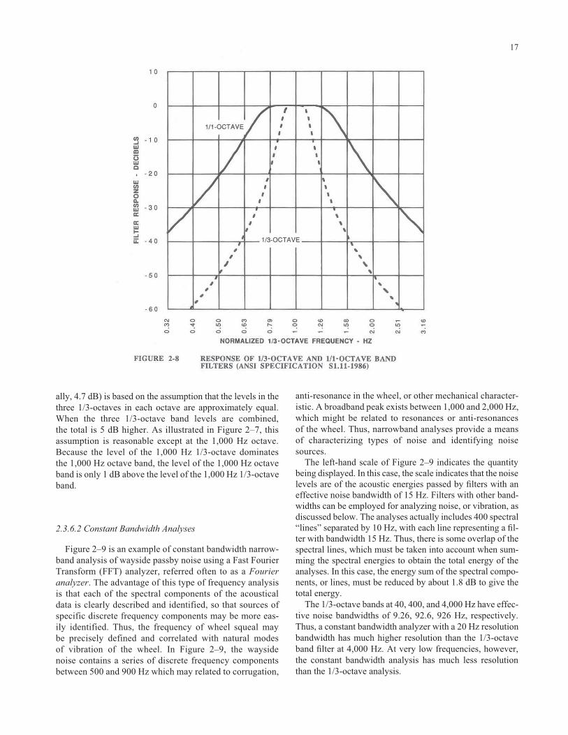
ally, 4.7 dB) is based on the assumption that the levels in thethree 1/3-octaves in each octave are approximately equal.When the three 1/3-octave band levels are combined, the total is 5 dB higher. As illustrated in Figure 2–7, thisassumption is reasonable except at the 1,000 Hz octave.Because the level of the 1,000 Hz 1/3-octave dominates the 1,000 Hz octave band, the level of the 1,000 Hz octaveband is only 1 dB above the level of the 1,000 Hz 1/3-octaveband.
2.3.6.2 Constant Bandwidth Analyses
Figure 2–9 is an example of constant bandwidth narrow-band analysis of wayside passby noise using a Fast FourierTransform (FFT) analyzer, referred often to as a Fourieranalyzer. The advantage of this type of frequency analysisis that each of the spectral components of the acousticaldata is clearly described and identified, so that sources ofspecific discrete frequency components may be more eas-ily identified. Thus, the frequency of wheel squeal may be precisely defined and correlated with natural modes of vibration of the wheel. In Figure 2–9, the wayside noise contains a series of discrete frequency componentsbetween 500 and 900 Hz which may related to corrugation,
17
anti-resonance in the wheel, or other mechanical character-istic. A broadband peak exists between 1,000 and 2,000 Hz,which might be related to resonances or anti-resonances of the wheel. Thus, narrowband analyses provide a meansof characterizing types of noise and identifying noisesources.
The left-hand scale of Figure 2–9 indicates the quantitybeing displayed. In this case, the scale indicates that the noiselevels are of the acoustic energies passed by filters with aneffective noise bandwidth of 15 Hz. Filters with other band-widths can be employed for analyzing noise, or vibration, asdiscussed below. The analyses actually includes 400 spectral“lines” separated by 10 Hz, with each line representing a fil-ter with bandwidth 15 Hz. Thus, there is some overlap of thespectral lines, which must be taken into account when sum-ming the spectral energies to obtain the total energy of theanalyses. In this case, the energy sum of the spectral compo-nents, or lines, must be reduced by about 1.8 dB to give thetotal energy.
The 1/3-octave bands at 40, 400, and 4,000 Hz have effec-tive noise bandwidths of 9.26, 92.6, 926 Hz, respectively.Thus, a constant bandwidth analyzer with a 20 Hz resolutionbandwidth has much higher resolution than the 1/3-octaveband filter at 4,000 Hz. At very low frequencies, however,the constant bandwidth analysis has much less resolutionthan the 1/3-octave analysis.

2.3.6.3 Spectrum Level and Power Spectral Density
The results of narrowband frequency analyses are com-monly presented in terms of spectrum level or power spec-tral density (PSD). The spectrum level of a noise is the levelthat would be measured if an analyzer had an ideal filterresponse characteristic with a bandwidth of 1 Hz at all fre-quencies. In other words, the level is normalized to a band-width of 1 Hz. The spectrum in Figure 2–9 can be convertedto a power spectral density level, or spectrum level, plot bysubtracting 11.8 dB (10 Log10[Effective Noise Bandwidth]).However, if the effective noise bandwidth exceeds the “line”width of the actual discrete frequency component, the resultwill be in error, since the power spectral density is notdefined for discrete frequency components. Normalized lev-els, such as the spectrum level, or power spectral density, arenot accurate for characterizing discrete frequency compo-nents. Mathematically, the spectral density of a discrete fre-quency component of noise is infinite. Therefore, when dis-playing spectral data with discrete frequency components,the data should not be normalized for filter bandwidth. Themain uses of the power spectral density or spectrum level for-
18
mat are (1) comparing data taken with analyzers with differ-ent analysis bandwidths and (2) checking compliance withspecifications given in terms of spectrum level.
2.4 CHARACTERIZING NOISE ENVIRONMENTS
Noise produced by any transit system must be character-ized to determine the need for mitigation. The field ofacoustics is replete with descriptors and methods for doingthis, largely because of the many types of noise and the dif-ficulty in assessing human responses to noise. Some of thedescriptors that are used are described below.
2.4.1 Noise Criterion Curves
The Noise Criterion (NC) curves are commonly used fornoise criteria indoors and are widely used in architectural spec-ifications for HVAC systems. The NC curves are illustrated inFigure 2–10. The NC curves are used by plotting the octaveband levels against the NC curves, and the NC level for a par-

19

ticular octave band spectrum is the maximum NC curve thatthe spectrum touches. Hence, using the NC curves gives a rat-ing for the acceptability of an acoustic environment and indi-cates the octave band that dominates the overall rating.Another form of the NC curves called the preferred noise cri-teria (PNC) curves, designed to overcome some objections tothe NC curves, are also occasionally encountered. The NCcurves can be used to specify noise environments or evaluatenoise consisting of broadband and pure tones, and have beenapplied to rail transit groundborne noise in buildings.
2.4.2 Energy Equivalent Levels
Because noise, particularly outdoor noise, varies withtime, there is a need for measures of noise that account forthese variations. The most popular measures are based on anenergy dose, or equivalent noise energy, principle. An energydose or equivalent energy level is mathematically attractivefor combining the sound energies of differing sources orevents. Several of these noise descriptors are defined below:
Equivalent Sound Level—Leq. Sometimes referred to as theenergy average sound level over the period of interest, Leq iswidely accepted as a valid measure of community noise. Theequivalent sound level is equal to the equivalent steady noiselevel which in a stated time period would contain the sameenergy as time-varying noise during the same time period.Mathematically, it is defined as
where p(t) is the time varying pressure and p0 is the standardreference pressure of 20 micro-Pa (2�10 –5 N/m2). This ismathematically equivalent to the definition of rms levelgiven above. However, “rms” is typically used for muchshorter periods of time than Leq. The average sound level overa period of time T is often symbolized as Leq(T). Commonlyused descriptors are
Leq(h) � hourly averaged sound levelLeq(8h) � 8-hour averaged sound levelLeq(d) � average daytime sound levelLeq(n) � average nighttime sound level
The term “average” indicates energy average.
Day-Night Average Sound Level–Ldn. Ldn is a 24-houraverage sound level in which the nighttime noise levelsoccurring between 10:00 P.M. and 7:00 A.M. are increasedby 10 dBA before calculation of the 24-hour average. The 10dBA penalty is included to account for people’s increasedsensitivity to noise during the nighttime hours when manypeople are asleep and the background noise is low. Ldn is the
Lt t
p tp
dteq
t
t
=−
( )⎡
⎣⎢⎢
⎤
⎦⎥⎥∫10 1
102 1
2
02
1
2
Log
20
primary measure used for describing noise in EnvironmentalImpact Statements.
Community Noise Equivalent Level (CNEL). CNEL issimilar to the Ldn except that the 24-hour period is broken intothree periods: day (0700 to 1900), evening (1900 to 2200),and night (2200 to 0700). Penalties of 5 dBA are applied tothe evening period and 10 dBA to the nighttime period. Inmost cases, CNEL will be less than 0.5 dBA higher than theLdn, an insignificant difference which is often ignored.
2.4.3 Histograms
Figure 2–11 illustrates the statistical distribution, or his-togram, of fluctuating community noise. The vertical axis isthe percentage of time that the noise level indicated on thehorizontal axis is exceeded. Adding a transient noise sourcesuch as rapid transit trains that create relatively high noiselevels for relatively short periods of time will modify the his-togram as indicated in the figure. The train noise increasedthe level exceeded 1% of the time, but left the level exceeded10% of the time unchanged.
Histograms may be represented by levels exceeded “n” per-cent of the time, or Ln. The level exceeded n-percent of time isa widely used measure of environmental noise. Typical mea-sures are L1, L10, L50, L90, and L99. The time period can rangefrom a full 24-hour period to a several minute spot check. Toavoid confusion, the time period should be clearly specified.The statistical levels are usually determined from histogramsdeveloped with the “fast” sound-level meter response, or rms averaging time of 1 sec. In practice, the “slow” meterresponse is often used. This will affect the extreme ends of the histogram, but should not affect the L10 or L50 significantly.
The levels exceeded 50% of the time are largely unaf-fected by transient events which, together, occur over aperiod of time less than 30 min in any hour. For this reason,the median noise level, L50, is a robust descriptor of timevarying community noise levels against which transientnoise levels may be projected. The L1 is often used todescribe the “maximum level,” and the L90 is often used todescribe the background sound level.
Histograms are usually developed for A-weighted soundlevels, but can be developed for 1/3-octave, and octave soundlevels, as well as for vibration levels. Histograms and therelated Ln’s are one of the most practical tools available fordescribing nonstationary, or time varying, community noise.
2.5 SOUND ABSORPTION ANDTRANSMISSION
Sound absorption and sound isolation are commonly mis-understood parameters. Sound absorption refers to the abil-ity of materials, such as fiberglass blankets or acoustical tile,to convert sound energy into heat. Sound absorbing materi-

21
als reduce sound reflected from a surface by dissipatingacoustical energy in the material. Porous materials do notstop, block, or contain sound. If air passes through or arounda material, so can sound. Sound transmission loss refers tothe ability of a partition or barrier to attenuate sound as ittransmits through. A material must be massive and airtight toeffectively isolate sound.
Figure 2–12 illustrates the reflection and transmission ofsound energy. The incident sound intensity impinges on thewall. Part of the sound intensity is transmitted through thewall, and part of the sound power is reflected from the wall.Another part is absorbed in the wall. The absorption coeffi-cient of the wall determines the intensity of the reflectedsound relative to the intensity of the incident sound, includesthe effect of both the sound intensity transmitted through thewall as well as the sound intensity absorbed by the materialin the wall. The sound absorption coefficient is alwaysbetween 0 and 1, though published values of the coefficientmay exceed 1 because of the methods of measurement. Thetransmission coefficient is the ratio of transmitted soundintensity to incident sound intensity, and is always between0 and 1. The sound transmission loss in decibels is a conve-nient descriptor of the sound isolation qualities of the wall.These quantities are mathematically defined as

Sound Absorption Coefficient (�) � 1 – Irefllecte/Iincident2
Transmission Coefficient (�) � ITransmitted/IIncident
Transmission Loss in Decibels (TL) � 10 Log (1/�)
An absorption coefficient of zero indicates perfect reflec-tion of incident sound energy. An absorption coefficient ofone indicates a perfectly nonreflecting wall, which may bedue to complete absorption of sound energy, perfect trans-mission of sound energy through the wall, or a combinationof both which produces a nonreflecting wall. For example,an opening in a wall would have an absorption coefficientof one. (Actually, at long wavelengths relative to thedimension of the opening, the absorption coefficient mayexceed one.)
The sound absorptive properties of a material depend onthe porosity and thickness, or dynamic response, of the mate-rial, and the angle at which the sound waves strike the mate-rial. For convenience, the reported absorption coefficient isgenerally the average over all angles of incidence, sometimesreferred to as the random incidence absorption coefficient.
2.5.1 Sound Transmission Loss
The sound transmission loss (TL) represents the loss indecibels of the sound intensity as it transmits through thewall or barrier. Sound transmission loss is given in decibels.A wall with a large sound transmission loss is a very effec-tive sound isolator, and a wall with zero transmission loss isacoustically transparent.
2.5.2 Sabine Absorption Coefficient
The Sabine absorption coefficient is very similar to theabsorption coefficient defined above, but is the absorptioncoefficient determined for a patch of material placed on thefloor of a reverberation chamber. The Sabine absorptioncoefficient is often greater than one, owing to the method ofmeasurement. More discussion of the Sabine absorptioncoefficient can be found in Beranek’s work (2).
2.5.3 Noise Reduction Coefficient–NRC
The noise reduction coefficient, or NRC, is a single-number descriptor of the sound absorbing properties of var-ious materials. The NRC is the arithmetic average of the“Sabine absorption coefficients” at 250, 500, 1,000 and2,000 Hz.
22
2.5.4 Sound Transmission Class–STC
The sound transmission class, or STC, is a single-numberdescriptor of the sound transmission losses of partitions.Information on determining the STC can be found inBeranek’s work, referenced above. As a general rule, parti-tions with high values of STC have high sound transmissionlosses.
2.5.5 Materials and Mounting
Materials such as glass-fiber insulation have high absorp-tion coefficients but very low transmission loss, while solidmaterials such as concrete have relatively high transmissionloss but very low absorption coefficients. Mounting glass-fiber blankets on a concrete wall will result in both hightransmission loss and high absorption. Manufacturers pro-vide data on the sound absorption coefficients and soundtransmission losses of various materials and partitions. Morediscussion is provided concerning sound transmission lossand sound absorption coefficient where appropriate, spe-cifically in the chapters concerning station and vent shafttreatments, and vehicle noise control.
2.6 REFERENCES
1. Harris, C. M. ed., Handbook of Noise Control, 2nd editionMcGraw-Hill Book Company, New York, NY (1979).
2. Beranek, L.L. ed., Noise and Vibration Control, McGraw-HillBook Company, New York, NY (1971).
3. Rettinger, M. Acoustic Design and Noise Control, Vols. 1 and 2,Chemical Publishing Co., New York, NY (1977).
4. Kinsler, L. and A. Frey, Fundamentals of Acoustics, John Wileyand Sons, New York, NY (1962).
5. Transportation Noise and Its Control, U.S. Government Print-ing Office, Washington, DC, stock No. 5000–0057, U.S. DOT,Office of the Secretary, Washington, DC (1972).
6. Lutz, R. Theory and Practical Application of Noise and Vibra-tion Abatement for Railway Vehicles, Report DT 25/E, Office for Research and Experiments of the International Union of Railways, ORE (April 1976).
7. Saurenman, H. J., J. T. Nelson, and G. P. Wilson, Handbook ofUrban Rail Noise and Vibration Control, prepared by Wilson,Ihrig & Associates, Inc., for U.S.DOT, UMTA, DOT-TSC-UMTA–81–72. NTIS No. UMTA-MA–06–0099–82–1 (Febru-ary 1982).
8. American National Standards Institute Specification ANSIS1.11 (1986).
9. American National Standards Institute Specification ANSI S1.6(1967).

23
CHAPTER 3 DESIGN GUIDELINES
3.1 Introduction, 253.2 American Public Transit Association, 25
3.2.1 Wayside Noise Limits, 253.2.1.1 Community Categories, 253.2.1.2 Measurement of Wayside Passby Noise, 253.2.1.3 Relation to Equivalent Levels–Leq, 27
3.2.2 Ancillary Facility Noise, 273.2.3 Station Platform Noise Levels, 273.2.4 Transit Vehicle Noise Limits, 27
3.3 Federal Transit Administration, 273.3.1 Transit System Projects, 28
3.3.1.1 Basis, 303.3.1.2 Land Use Categories, 303.3.1.3 Levels of Impact, 313.3.1.4 Mitigating Adverse Impact, 31
3.4 Local Ordinances, 313.5 Preparation of Noise Specifications, 313.6 References, 32

This page left intentionally blank.

25
CHAPTER 3
DESIGN GUIDELINES
3.1 INTRODUCTION
Environmental impact analysis and design guidelines arediscussed in this chapter. Included are (a) the design guide-lines published by APTA and (b) the guidelines recently pub-lished by the FTA for environmental assessment and designof rail transit projects and highway/transit corridor projects.The FTA provides criteria for assessing and comparing noiseimpacts of various transportation modes, including bus aswell as ancillary facilities of transit systems. Also discussedin this chapter are local ordinances and the preparation ofnoise specifications for transit equipment.
3.2 AMERICAN PUBLIC TRANSITASSOCIATION
APTA provides design guidelines for noise produced bytransit trains. These guidelines are comprehensive; theyinclude limits for vehicle interior, exterior, station platform,and fan and vent shaft noise levels (1). (Noise level limits arealso provided for fan noise and substation noise.)
3.2.1 Wayside Noise Limits
Wayside noise limits are recommended by APTA, basedon community categories and building types.
3.2.1.1 Community Categories
Community categories defined by the APTA guidelinesare listed in Table 3–1 in terms of description and median L50
sound levels. These basic community categories serve as abasis for recommending appropriate noise level limits. Eachcommunity category is assigned a range of ambient mediansound levels, L50, as part of its description, which forms abasis for assigning rail transit noise limits. The noise limitsare intended to limit maximum passby noise to levels con-sistent with other modes of transportation, such as automo-biles passing along streets in front of residential receivers.Design guidelines for maximum rail transit noise are thenselected for the type of community.
Design guidelines for maximum passby noise levels areprovided in Table 3–2 for various types of communities andoccupancies. The APTA guidelines place a limit on maxi-
mum sound levels so that they are comparable to othersources of noise, such as automobiles and light trucks. Theselimits are applied to nighttime operations, because the sensi-tivity to noise is greater at night than during daytime hours.In practice, wheel/rail noise will be independent of the timeof day. The noise limits apply outdoors at the building or areaunder consideration, but not closer than 50 ft from the (near-est) track centerline. At locations where the train noise hasno particularly annoying or identifiable components, experi-ence with the noise level guidelines given in Table 3–2 hasshown that the community will usually accept the resultingnoise environment if the maximum noise level design goalsare met, in spite of the transient nature of wheel/rail noise.More importantly, the APTA guidelines can be met withpractical noise control provisions.
Maximum sound levels for specific types of buildings areindicated in Table 3–3. These limits should be appliedregardless of the community area category involved. Thedesigner should be careful in locating surface or aerial transit lines adjacent to auditoria, television studios, schools,theaters, amphitheaters, and churches.
At locations where noise from impacts at jointed track or crossovers, wheel squeal on curves, and so on occur, the noise will be more annoying than usual. The APTAguidelines make no provision for these types of noise.
3.2.1.2 Measurement of Wayside Passby Noise
The maximum sound level is defined as the maximumsound level measured with a sound level meter set to the “fastmeter response,” which is similar to an rms averaging timeof 0.125 sec. In practice, the rms sound level is often deter-mined by averaging the sound energy over the passby dura-tion to average out minor fluctuations in sound level due toabnormally rough wheels, impacts, etc., as might be donewith an integrating sound level meter or real time analyzer.Minor fluctuations of noise level can also be energy averagedusing the “slow” sound level meter response characteristic,equivalent to an rms averaging time of 1 sec. The differencebetween the “slow” sound-level meter measurement and the“fast” sound-level meter measurement for a smoothly vary-ing train passby signature is a fraction of a decibel. A prob-lem may arise, however when measuring the maximumsound level using the slow meter response for very rapidly


rising passby noise levels, in which case the fast sound-levelmeter response should be used. Most trains require at least 1sec to pass a measurement location, a time that is consistentwith the slow meter response. The slow meter response isentirely adequate for measuring maximum passby noise fromheavy rail transit trains of four or more cars at distancesbeyond one car length.
3.2.1.3 Relation to Equivalent Levels � Leq
The maximum noise level limits indicated by the APTAguidelines limits may be correlated with energy averagednoise levels for the purpose of assessing community reactionto noise. The following formula by Peters (2) is useful torelate the maximum passby level measured with a soundlevel meter set to “fast” response (0.125 sec integration time)with the energy averaged Leq over an extended period:
Leq � Lmax � 10 Log10{R(1.5D � d )/v} � 30
where:R � number of trains per hourD � distance of the receiver from the track centerlined � average train length in metersv � train speed in km/hr.
As an example, if the 70 dBA design limit is just met at alocation 60 m from the track, with train speed of 96 km/hr,and average train length of 91 m, then an Ldn of 55 dBAwould be obtained with an average of 16 trains per hour dur-ing the daytime (7:00 AM to 10:00 PM) and 1.5 trains perhour at night.
For the most part, the APTA guidelines for communitynoise levels due to transit trains agree with the goals of theEnvironmental Protection Agency (EPA) “Levels Docu-ment” (3). Meeting the APTA maximum noise level goals forresidential locations will not necessarily guarantee that theDay-Night Levels identified in the “Levels Document” as“requisite to protect the public health and welfare with anadequate margin of safety” will be achieved. Even if themaximum level goals of the APTA guidelines are achieved,the Day-Night Levels will depend on scheduling, especiallyon the number of trains passing during the nighttime period.
3.2.2 Ancillary Facility Noise
The APTA guidelines provide noise level limits for ancil-lary facilities, including vent and fan shafts through whichwheel/rail noise may propagate and impact normally quietresidential communities. The maximum limits for transientnoise emanating from fan and vent shafts due to train opera-tions are listed in Table 3–4. These limits apply at the shorterdistance of 50 ft from the ancillary facility or at the setbackline of the nearest building.
27
3.2.3 Station Platform Noise Levels
The APTA guidelines recommendations for station plat-form noise levels due to trains are summarized in Table 3–5.Trains entering and leaving subway stations should not pro-duce noise levels in excess of 85 dBA. The noise level lim-its for above grade stations are 80 and 85 dBA for ballast-and-tie and concrete track beds, respectively. Noise levels 5dB below these limits are desirable. Platform noise levels arenormally measured at 5 ft above the platform, roughly mid-way between the platform edge and rear wall, or 5 ft from theplatform edge, whichever is closer to the track. The noiselevels apply to the total noise level, including noise due towheel/rail sources as well as traction motor equipment, vehi-cle ventilation and air conditioning equipment, and brakesystems. (The APTA guidelines also provide limits for con-tinuous noise levels due to station and subway ventilationfans, and recommend station reverberation times to controlspeech intelligibility of public address systems.)
3.2.4 Transit Vehicle Noise Limits
Interior and exterior vehicle noise generally have separatestandards, though the sources are the same. The APTA guide-lines recommend limits for vehicle interior and exterior oper-ational maximum A-weighted noise levels at maximum oper-ating speeds on ballast-and-tie and concrete track beds. Theselimits are listed in Table 3–6. (The APTA guidelines also rec-ommend maximum auxiliary equipment noise levels for sta-tionary vehicles.) These limits are incorporated into manytransit vehicle procurement specifications. The goal of theAPTA guidelines is that vehicles be constructed to minimizewayside and interior noise levels. Further, the limits given inTable 3–6 apply to the total noise produced by the transit vehi-cle, not just wheel/rail noise. Much of the noise produced bya transit vehicle on ballast-and-tie track with smooth groundrail is produced by traction motor equipment and aerodynamicturbulence in the truck area. Subjectively, meeting the APTAguidelines for interior noise levels means that the interiornoise on ballast-and-tie track at low speeds should be “quiet”while at high speeds in subway the noise may be “intrusive”but not “annoying” (4). These levels are consistent with thoseof all but the quietest of automobiles at highway speeds.
3.3 FEDERAL TRANSIT ADMINISTRATION
The FTA provides comprehensive guidelines for environ-mental assessment of proposed transit projects in a reportentitled Transit Noise and Vibration Impact Assessment (5),referred to informally as the “guidance manual.” The FTAguidelines recommend procedures for assessing transit noiseimpacts due to all forms of transit, including rail transit. TheFTA expects project sponsors to use these guidelines for railprojects which involve funding assistance from the FTA.
The purpose of this section is to introduce and summarizethe FTA guidance for environmental noise impact assessment.
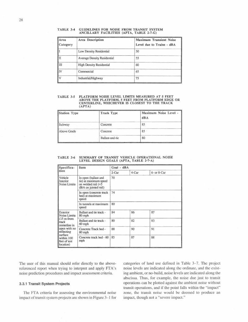
The user of this manual should refer directly to the above-referenced report when trying to interpret and apply FTA’snoise prediction procedures and impact assessment criteria.
3.3.1 Transit System Projects
The FTA criteria for assessing the environmental noiseimpact of transit system projects are shown in Figure 3–1 for
28
categories of land use defined in Table 3–7. The projectnoise levels are indicated along the ordinate, and the exist-ing ambient, or no-build, noise levels are indicated along theabscissa. Thus, for example, the noise due just to transitoperations can be plotted against the ambient noise withouttransit operations, and if the point falls within the “impact”zone, the transit noise would be deemed to produce animpact, though not a “severe impact.”

29

3.3.1.1 Basis
The FTA criteria base the degree of environmental impactin part on existing ambient noise levels. As stated in the guidance manual, they incorporate both absolute criteria,which consider activity interference caused by the transitproject alone, and relative criteria, which consider annoyancedue to the change in the noise environment caused by thetransit project. The level or magnitude of impact is deter-mined by two factors: predicted project noise and existingnoise. In the mid-range, the impact criteria allow higher pro-ject noise levels as existing noise levels increase. However,there is an absolute limit placed on project noise at the higherambient levels, as reflected in Figure 3–1, where the ascend-ing curves flatten out.
An important aspect of the FTA noise impact criteria isshown in Figure 3–2. This figure illustrates the cumulative,or total, increase in noise allowed by the impact criteria atdifferent ambient noise levels. As the ambient noise en-vironment gets louder, the increase in cumulative noiseallowed by the criteria gets smaller. This aspect recognizesthat people already exposed to high ambient noise levels areleast able to tolerate increases in noise due to introduction ofa new noise source.
As illustrated in Figure 3–2, areas where existing noiselevels are low (Ldn less than 40 dBA) may suffer a 10 dBAincrease in noise level without being described as being sig-nificantly impacted by the project. Conversely, areas with abackground level on the order of 70 to 75 dBA (e.g., near ahighway) may experience a noise increase of only a few deci-bels by the project and be described as being impacted by theproject. A very attractive feature of the FTA criteria is thatthey help to reduce “incrementalization” of noise impactsdue to multiple projects; adding to already excessively high
30
noise levels on the order of 80 dBA is not necessarily anappropriate approach. Few criteria for environmental assess-ment have this desirable feature.
3.3.1.2 Land Use Categories
The FTA criteria are defined separately for three differentcategories of land use, as defined in Table 3–7. Category 1includes tracts of land where quiet is a basis for use, such asoutdoor pavilions or National Historic Landmarks whereoutdoor interpretation routinely takes place. The hourlyequivalent level, Leq (h) applies to these areas. Category 2includes residences and buildings where people sleep, forwhich the Day-Night level, Ldn, is to be used. Category 3areas include schools, libraries, churches, certain parks, andother institutions frequented during the daytime and eveningperiods, for which the hourly equivalent level, Leq(h), applies.The hourly Leq used for Category 1 and 3 areas is the hourlyLeq for the noisiest hour of transit related activity during thehours of land use. As indicated in Figure 3–1, the projectnoise limits for Category 3 areas may be 5 dB higher than thelimits for Category 1 and 2 areas.
The criteria do not apply to industrial or commercial areaswhich are compatible with high noise levels. However, com-mercial establishments that require quiet as a basis for usewould be subject to the criteria, such as motion picture orrecording studios. The application of the criteria to histori-cal structures depends on their use and location. Thus, historical structures used as commercial shops in noisydowntown areas would not be subject to the criteria. Histor-ical transportation structures, such as railroad stations,would not be considered noise sensitive, simply on the basisof their use.

3.3.1.3 Levels of Impact
The terms “no impact,” “impact,” and “severe impact”may be interpreted as follows:
No Impact. The project, on average, will result in an“insignificant increase in the number of people highlyannoyed by new noise.” The term “highly annoyed” is vague,but usually refers to people willing to engage in litigation or,at the very least, complain about the noise to local officialswith threat of litigation.
Impact. This is a moderate impact. The change in cumulativenoise is noticeable to most people, but may not be sufficientto cause strong, adverse community reactions. Other project-specific factors must be considered to determine the need formitigation, such as the types and numbers of noise-sensitiveland uses.
Severe Impact. A significant percentage of people would be highly annoyed by the noise, perhaps resulting invigorous community reaction attended by litigation.
Categories 1 and 2 impact criterion curves for “impact”and “severe impact” are constant at project noise levels of 65and 75 dBA for existing ambient noise levels in excess of 71and 77 dBA, respectively. Project noise levels greater than65 dBA or 75 dBA are considered an “impact” or “severeimpact,” respectively, regardless of the existing noise level.
The FTA criteria do not apply to most commercial or indus-trial land uses, unless quiet is a basis for such use. Examplesof industries which would fall under the purview of the FTAcriteria include sound and motion picture recording studios. Aword of caution is appropriate, however. Many motion pictureor sound recording studios require very low ambient back-ground sound levels of about 15 dBA to allow use of the facil-ity for modern digital sound mastering. Also, commercialbuildings in areas of restricted automobile or truck usage, suchas open malls, may be impacted by transit noise.
3.3.1.4 Mitigating Adverse Impact
The FTA noise impact criteria provide a framework forassessing the magnitude of impact from proposed projects.The criteria are based on human response to noise and do notincorporate considerations of feasibility, practicality or costof reducing adverse noise levels. Once the magnitude ofimpact has been established during the enviornmental reviewprocess, FTA works in cooperation with the project sponsorto determine the need for noise mitigation. The guidancemanual does not establish a requirement to mitigate noise atany specific impact level, although “severe impact” presentsthe most compelling case to reduce noise. The manual out-lines the project-specific factors that must be considered indetermining the need for mitigation. Considerations includethe number and types of noise-sensitive sites, the level ofexisting noise and level of increase due to the project, and the
31
benefits and cost of mitigation treatments. The reader isreferred to the guidance manual for a fuller explanation ofhow mitigation is addressed.
3.4 LOCAL ORDINANCES
Local noise ordinances may restrict rail transit noiselevels. Thus, when planning a new transit facility, orresponding to complaints from city or county inhabitants,local noise ordinances should be reviewed to determine if any potential conflicts exist. Often, rail transit noise is not considered in developing a noise ordinance, and theresult is that rail transit noise might not be compatible withsome noise ordinances if strictly interpreted. In such cases,rail transit systems are asked to meet noise standards that aremore restrictive than those for automobiles. For this reason,community understanding of the technical problems facingthe transit system designer is important, as is recognition bythe designer of local standards for peace and quiet.
When transit corridors are located in residential communi-ties, noise levels invariably exceed the usual limits for contin-uous noise. This is true for most modern types of transporta-tion including automobiles, buses, and rail transit systems.Recognizing the problem, most modern noise ordinancesinclude specific, but separate, limits on motor vehicle trafficnoise levels. If rail transit was not considered when an ordi-nance was prepared, it may be that the train noise is exempt.However, either a modified ordinance may be required thatspecifically covers rapid transit systems, or a variance may berequired. Without special consideration, the transit systemmight have to comply with unrealistic noise limits.
Way and structure maintenance such as rail grinding can bevery noisy. These operations are most often scheduled atnight, a period when residential communities are most sensi-tive to noise, and when local ordinances are most restrictive.The possibility of local noise ordinances being exceeded bytransit maintenance work should be checked. This is particu-larly relevant to the design of effective rail grinding programsfor controlling rail corrugation. A mitigating factor in suchmaintenance work as rail grinding is the reduction ofwheel/rail wayside noise, a long-term benefit achieved withpossibly a short-term noise impact. In this case, the commu-nity should be made aware of the long-term noise reductionbenefits of rail grinding, and, as a result, there should be anincrease in the community’s acceptance of maintenance-related noise. Even in this case, efforts should be made to con-trol maintenance-related noise to the extent that is practical.
3.5 PREPARATION OF NOISESPECIFICATIONS
A comprehensive program for control of wheel/rail noiseincludes the development of criteria and specifications for newfacilities and equipment. Documents for virtually all majorpurchases of rail transit equipment now include specificationsfor maximum acceptable limits of noise and vibration.
In developing noise specifications or criteria, one mustreach compromise between levels that are technically andeconomically feasible and levels that will minimize theadverse impact of noise on people and structures. An exam-ple specifications for transit vehicle procurements is pro-vided in the Handbook of Urban Rail Noise and VibrationControl (see Chapter 2 references).
Of particular interest in the specification for transit vehi-cles is the designation of a minimum sound transmission lossfor each of the characteristic sections of the car body,because most interior noise is generated exterior to the vehi-cle. This is particularly important for vehicles travelingthrough subways, where wheel/rail noise is the dominantinterior noise. Even on at-grade ballast-and-tie track, inade-quate floor sound insulation may result in unnecessarily highinterior noise levels.
32
3.6 REFERENCES
1. “Noise and Vibration,” Guidelines and Principles for Design ofRapid Transit Facilities, Section 2.7, APTA, Washington, D.C.(1979).
2. Peters, S. “The Prediction of Railway Noise Profiles,” Journalof Sound Vibration, Vol. 32, No. 1 (1974) pp. 87–99.
3. Information on Levels of Environmental Noise Requisite to Pro-tect Public Health and Welfare with an Adequate Margin ofSafety, Final Report (Commonly referred to as the “Level Doc-ument”), 550/9–74–004, U.S. EPA, Washington, D.C. (March1974).
4. Byron, M.E. “A Tentative Criterion for Acceptable Noise Lev-els in Passenger Vehicles,” Journal of Sound and Vibration, Vol.48, No. 4 (1976) pp. 525–535.
5. Transit Noise and Vibration Impact Assessment, Harris, Miller,Miller & Hanson, Inc. for the Office of Planning, FTA, U.S.DOT-T–95–16 (April 1995).
33
CHAPTER 4 WHEEL/RAIL NOISE GENERATION
4.1 Introduction, 354.2 Tangent Track Noise, 35
4.2.1 Normal Rolling Noise, 354.2.1.1 Characterization of Normal Rolling Noise, 354.2.1.2 Rolling Noise Generating Mechanisms, 364.2.1.3 Parallel Mechanical Impedance Model, 384.2.1.4 Wheel/Rail Roughness, 404.2.1.5 Wheel Mechanical Impedance, 404.2.1.6 Rail Mechanical Impedance, 414.2.1.7 Contact Stiffness, 424.2.1.8 Wheel/Rail Conformity, 434.2.1.9 Noise Radiation, 434.2.1.10 Directivity, 444.2.1.11 Attenuation with Distance, 46
4.2.2 Excessive Rolling Noise, 504.2.3 Impact Noise from Rail Imperfections, Joints, and Wheel Flats, 50
4.2.3.1 Smooth Irregularity, 504.2.3.2 Level and Decreasing Elevation Rail Joints and Wheel Flats, 504.2.3.3 Step-Up Rail Joints, 514.2.3.4 Summary of Impact Noise, 51
4.2.4 Corrugated Rail Noise, 514.2.4.1 Characterization, 514.2.4.2 Wheel/Rail Interaction at Corrugated Rail, 52
4.3 Curving Noise, 544.3.1 Wheel Squeal, 54
4.3.1.1 Causes of Wheel Squeal, 554.3.1.2 Lateral Slip Model, 584.3.1.3 Loss Factor Due to Stick-Slip, 604.3.1.4 Effect of Internal Loss Factor, 614.3.1.5 Friction, 61
4.3.2 Wheel/Rail Howl, 634.3.2.1 Mechanism of Wheel/Rail Howl, 634.3.2.2 Relation to Rail Corrugation, 63
4.4 Special Trackwork, 644.5 References, 64

This page left intentionally blank.

35
CHAPTER 4
WHEEL/RAIL NOISE GENERATION
4.1 INTRODUCTION
This chapter discusses the basic theory of wheel/rail noisegeneration for tangent track, curved track, and special track-work to provide a foundation for making informed decisionsconcerning treatment. The mechanisms involved are exceed-ingly complex, and the reader is referred to the literature formore detailed discussions than those provided here.
There have been substantial advances in the theories con-cerning wheel/rail noise generation during the 1970s and1980s, and research in the area is continuing, especially withrespect to high speed rail. The theory of wheel/rail noise gen-eration, though highly developed, is incomplete. The effectof wheel and rail profiles on wayside noise from tangenttrack is being studied, but contradictions exist. Wheel squealtheory is also subject to some inconsistency with respect tofield experience. In general, however, this fascinating andchallenging field of noise control is rich with topics for theoretical and experimental work.
There are several descriptive terms for various types ofwheel/rail noise. The terms rolling noise and tangent tracknoise are both used here to refer to noise produced by rail andwheel roughness and material heterogeneity. Rolling noisealso occurs at curved as well as tangent track. The termimpact noise refers to noise generated by rail imperfections,joints, and more significantly, special trackwork. Much oftangent track rolling noise at severely worn rail or with flat-ted wheels may include substantial impact noise due towheel/rail contact separation. The terms wheel squeal andcurving noise both refer to the noise generated at curves.Curving noise includes both wheel squeal and wheel/railhowl, the latter being the less common. While wheel squealis due to a stick slip phenomenon involving nonlinear inter-action of the wheel with the rail, wheel/rail howl, also com-mon at curves, is less clearly defined.
Tangent track rolling noise is considered first, followed bya discussion on curving noise. Finally, the researchers con-clude with a short discussion of special trackwork noise.
4.2 TANGENT TRACK NOISE
Tangent track noise is due to wheel and rail roughness,which may include rail corrugation and random surfacedefects. Tangent track noise is subdivided into (1) normal
rolling noise for smooth ground rail and trued wheels; (2)rolling noise due to excessively roughened rails and wheels;(3) impact noise due to pits and spalls of the rail and wheelrunning surfaces, wheel flats, and rail joints; and (4) rail cor-rugation noise. These categories form a basis for discussionof tangent track noise and selection of noise control proce-dures. The term wheel/rail roar is often used to refer torolling noise of all types, while roaring rail has been used torefer to corrugated rail noise.
Tangent track normal and excessive rolling noise are dis-cussed within the context of a linear theory of wheel/railinteraction, relying on rail and wheel roughness as the pri-mary cause. Another cause of wheel/rail noise may be het-erogeneity of the rail steel moduli, for which the linear the-ory presented here may not be entirely adequate. Further,with sufficiently large amplitude roughness, as with severelycorrugated rail, or with severely flatted wheels, wheel/railcontact separation may occur, producing impact noise. Aseparate theory of impact noise is presented after the discus-sions of normal and excessive noise, and before the discus-sion of rail corrugation noise.
4.2.1 Normal Rolling Noise
Noise in the absence of wheel and rail imperfections ordiscontinuities, such as wheel flats, spalls, rail corrugation,joints, and so on is termed normal rolling noise. Normalrolling noise is the baseline condition for which most newrail transit systems are designed, and departures therefromconstitute a degradation of condition and performance withrespect to noise control. This baseline condition is the statethat operating rail transit systems should be striving for orpreserving. There is also an important side benefit associatedwith a quiet system: smooth rolling surfaces produce lessvibration of various trackwork and truck components, thusextending life and, possibly, reducing operational costs.
4.2.1.1 Characterization of Normal Rolling Noise
Tangent track rolling noise has a broadband frequencyspectrum, often with a broad peak between 250 and 2,000Hz. At systems with adequate ground rail and trued wheels,traction motor cooling fan and gearbox noise and undercar

aerodynamic noise may contribute significantly to opera-tional noise, and some care must be exercised in identifyingthe wheel/rail noise component. Representative samples of1/3-octave band wayside noise produced by a Bay AreaRapid Transit (BART) vehicle at various speeds are pre-sented in Figure 4–1. In this example, traction power equip-ment produces the peak in the spectrum at 250 Hz. At higherfrequencies, wheel/rail noise dominates the spectrum, peak-ing at about 1,600 Hz. With trued wheels and smooth groundrail on ballast and ties, BART is one of the quietest vehiclesin operation at U.S. transit systems.
A whine may also occur because of a periodic grindingpattern in the rail running surface, as evidenced by the peakat about 1,600 Hz in the 80 mph data shown in Figure 4–1.At lower speeds, this peak is reduced in frequency, consis-tent with a wavelength in the rail of about 3 ⁄4 in. long. With-out this component, the passby noise would have been lessthan measured by a few decibels.
The high levels of low-frequency noise below 125 Hz arelikely due to aerodynamic sources in view of the relativelylarge difference between the 60 and 80 mph data in this fre-quency range. If there is difficulty in distinguishing thewheel/rail noise component from traction power equipment
36
noise and other under car equipment noise, then wheel/railnoise is probably not excessive, and efforts at noise controlmight be directed toward traction power equipment (1)
With normal rolling noise, the rail running surface will befree of spalls, checks, pitting, burns, corrugation, or othersurface defects, which may not be entirely visible. The wheeland rail provide running surfaces which, under ideal condi-tions, should have similar characteristics for smoothness andlow noise as any anti-friction bearing. From a practical per-spective, ideal bearing surfaces are difficult to realize andmaintain in track due to lack of lubricant, corrosion and contamination, and dynamic wheel/rail interaction forces.
4.2.1.2 Rolling Noise Generating Mechanisms
Four generating mechanisms have been suggested in theliterature as sources of normal rolling noise. These include
• Rail and wheel roughness,• Parameter variation, or moduli heterogeneity,• Creep, and• Aerodynamic noise.
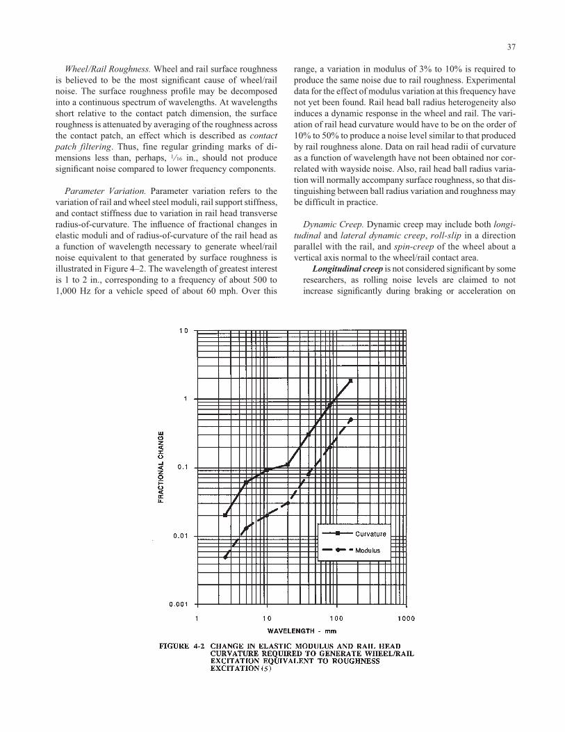
Wheel/Rail Roughness. Wheel and rail surface roughnessis believed to be the most significant cause of wheel/railnoise. The surface roughness profile may be decomposedinto a continuous spectrum of wavelengths. At wavelengthsshort relative to the contact patch dimension, the surfaceroughness is attenuated by averaging of the roughness acrossthe contact patch, an effect which is described as contactpatch filtering. Thus, fine regular grinding marks of di-mensions less than, perhaps, 1 ⁄16 in., should not produce significant noise compared to lower frequency components.
Parameter Variation. Parameter variation refers to thevariation of rail and wheel steel moduli, rail support stiffness,and contact stiffness due to variation in rail head transverseradius-of-curvature. The influence of fractional changes inelastic moduli and of radius-of-curvature of the rail head asa function of wavelength necessary to generate wheel/railnoise equivalent to that generated by surface roughness isillustrated in Figure 4–2. The wavelength of greatest interestis 1 to 2 in., corresponding to a frequency of about 500 to1,000 Hz for a vehicle speed of about 60 mph. Over this
37
range, a variation in modulus of 3% to 10% is required toproduce the same noise due to rail roughness. Experimentaldata for the effect of modulus variation at this frequency havenot yet been found. Rail head ball radius heterogeneity alsoinduces a dynamic response in the wheel and rail. The vari-ation of rail head curvature would have to be on the order of10% to 50% to produce a noise level similar to that producedby rail roughness alone. Data on rail head radii of curvatureas a function of wavelength have not been obtained nor cor-related with wayside noise. Also, rail head ball radius varia-tion will normally accompany surface roughness, so that dis-tinguishing between ball radius variation and roughness maybe difficult in practice.
Dynamic Creep. Dynamic creep may include both longi-tudinal and lateral dynamic creep, roll-slip in a direction parallel with the rail, and spin-creep of the wheel about a vertical axis normal to the wheel/rail contact area.
Longitudinal creep is not considered significant by someresearchers, as rolling noise levels are claimed to notincrease significantly during braking or acceleration on
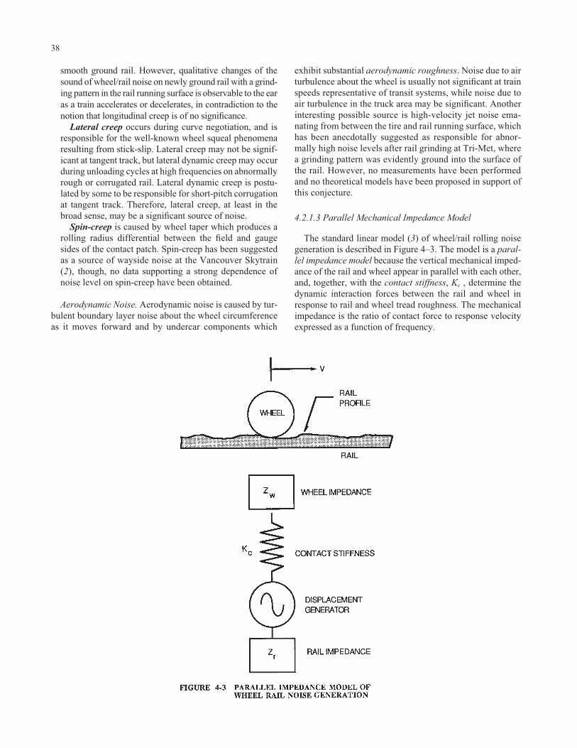
smooth ground rail. However, qualitative changes of thesound of wheel/rail noise on newly ground rail with a grind-ing pattern in the rail running surface is observable to the earas a train accelerates or decelerates, in contradiction to thenotion that longitudinal creep is of no significance.
Lateral creep occurs during curve negotiation, and isresponsible for the well-known wheel squeal phenomenaresulting from stick-slip. Lateral creep may not be signif-icant at tangent track, but lateral dynamic creep may occurduring unloading cycles at high frequencies on abnormallyrough or corrugated rail. Lateral dynamic creep is postu-lated by some to be responsible for short-pitch corrugationat tangent track. Therefore, lateral creep, at least in thebroad sense, may be a significant source of noise.
Spin-creep is caused by wheel taper which produces arolling radius differential between the field and gaugesides of the contact patch. Spin-creep has been suggestedas a source of wayside noise at the Vancouver Skytrain(2), though, no data supporting a strong dependence ofnoise level on spin-creep have been obtained.
Aerodynamic Noise. Aerodynamic noise is caused by tur-bulent boundary layer noise about the wheel circumferenceas it moves forward and by undercar components which
38
exhibit substantial aerodynamic roughness. Noise due to airturbulence about the wheel is usually not significant at trainspeeds representative of transit systems, while noise due toair turbulence in the truck area may be significant. Anotherinteresting possible source is high-velocity jet noise ema-nating from between the tire and rail running surface, whichhas been anecdotally suggested as responsible for abnor-mally high noise levels after rail grinding at Tri-Met, wherea grinding pattern was evidently ground into the surface ofthe rail. However, no measurements have been performedand no theoretical models have been proposed in support ofthis conjecture.
4.2.1.3 Parallel Mechanical Impedance Model
The standard linear model (3) of wheel/rail rolling noisegeneration is described in Figure 4–3. The model is a paral-lel impedance model because the vertical mechanical imped-ance of the rail and wheel appear in parallel with each other,and, together, with the contact stiffness, Kc , determine thedynamic interaction forces between the rail and wheel inresponse to rail and wheel tread roughness. The mechanicalimpedance is the ratio of contact force to response velocityexpressed as a function of frequency.

The roughness is indicated as a displacement generator inseries with the contact stiffness. The customary approach isto decompose the rail and wheel roughness amplitude into aspectrum of amplitude versus roughness wavenumber, k,equal to 2π divided by the wavelength, . The correspondingfrequency, f, of the sound due to roughness is related to vehi-cle speed, V, and roughness wavenumber as
f � kV � 2π/
Again, the roughness may be decomposed into an infinityof waves with associated wavelengths, . The spectra mayconsist of discrete wave components, such as with corru-gated rail, or may have a continuous spectrum of wave components, as with random roughness.
The model includes the various resonances of the wheelset and track support in the expressions for wheel and railmechanical impedances. Given the dynamic contact force,the vibration of the wheel may be predicted from the transfermobilities, or modal velocity responses, of the wheel to con-tact forces. A modal response is the vibration response of anobject at a natural vibration mode, and is associated with amodal, or natural, frequency.
The contact force can be expressed as a function of the par-allel combination of the mechanical impedances for thewheel and rail, and the roughness. Thus
where i is the square root of –1, is the radian frequency,2πf, and Z() is the frequency dependent parallel combina-tion of the impedances.
The contact mechanical impedance, Zc (), is given by
The velocity of the wheel tread at the contact patch, vt (),and rail head, vr (), neglecting deformation of the contactpatch, are given by
The entire discussion can be reformulated in terms of com-pliances, C(), through the relation
Ci Z
ωω ω
( ) =( )
1
v FZ
i ZZr
r r
ω ωω
ω ω δ ωω
( ) =( )( )
=( ) ( )
( )
v FZ
Z iZw
w w
ω ωω
ω ωδ ωω
( ) =( )( )
=( ) ( )
( )
Z Kic
cωω
( ) =
F i
Z Z Zc r w
ω ωδ ω
ω ω ω
ωδ ω ω( ) =( )
( )+
( )+
( )
= ( ) ( )1 1 1 i Z
39
In this case, the expressions for the contact force simplify to
The contact compliance, Cc, is assumed to be independent offrequency. The rail and wheel displacements in response tothe contact force become
The mechanical impedance functions for the wheel andrail can be rather complicated in the audio range. (Seebelow.) However, the above forms indicate that the ratios ofthe wheel and rail compliances to the parallel compliancedetermine the responses of the wheel and rail, respectively.In particular, if the contact stiffness is very large, the paral-lel impedance becomes the parallel impedance of the wheeland rail, with the contact patch stiffness contributinginsignificantly to the interaction. This is the usual conditionat frequencies below, perhaps, 100 Hz. If the contact stiffnessis sufficiently small, the parallel combination will be con-trolled by the contact compliance, in which case both thewheel and rail velocities, or displacements, will decrease. Ifthe wheel compliance is high with respect to both the contactand rail compliances, the wheel displacement will approachthe combined roughness, �(), of the rail and wheel, and therail displacement will approach zero. Conversely, if the railcompliance becomes very large relative to the wheel com-pliance, the rail displacement will approach �(), and thewheel displacement will decrease.
For normal running noise, where the wheels and rails arein good condition, the above model is expected to be a rea-sonable representation of the physics of wheel/rail interac-tion. The model ignores possible contact separation due toexcessive roughness or corrugation, which would result in anonlinear set of equations. Also not included in the model arelateral forces and responses, though these may be included(4). There are no expressions or information concerning lat-eral rail roughness, and lateral roughness is thereforeignored, though this may not be clearly justified with conicalwheels and canted rails. The model also ignores heterogene-ity of the rail steel moduli, and other parametric variationssuch as discrete rail supports with respect to the translatingvehicle, and variation of the ball radius of the rail head,which will modulate the contact stiffness. Roll-slip- or spin-creep-generated noise is similarly not included.
Current models of wheel/rail interaction are at a consider-ably higher state of development than that given above.These more complex models, including the British Railmodel of wheel/rail noise generation (TWINS), are discussedby Remington (5) and Thompson (6). A very thorough dis-cussion of high-frequency wheel/rail interaction models isprovided by Knothe and Grassie (7).
δ ω ω ω
δ ω ω ω
r r
w w
C F
C F
( ) = ( ) ( )
( ) = ( ) ( )
FC C Cr w c
ω δ ωω ω
( ) =( )
( ) + ( ) +

4.2.1.4 Wheel/Rail Roughness
Examples of measured rail roughness spectra are pro-vided in Figure 4–4. Wheel roughness is equally important,and the roughness, �(), appearing in the parallel impedancemodel should be taken as the square root of the sum of thesquares of the two roughnesses. The roughness spectra pro-vided in Figure 4–4 are in terms of 1/3-octave bands ofroughness wavenumber, k � 2π/, where is the wave-length in in. The 1/3 octave band displacement, or rough-ness, levels are in decibels relative to 1 micro-in. Thus, ifone were to “filter” the rail roughness by a 1/3-octave bandfilter centered at 16 radians per inch, the observed root-mean-square output of the filter would be 24 to 28 dB re 1micro-in., or about 15 to 25 micro-in. The actual frequencyof excitation is obtained by multiplying the wavenumber bythe train speed in inches per second and dividing by 2π.Thus, the wavenumber of 16 radians per inch (wavelengthequal to 0.393 in.) at a train speed of 60 mph (1,056 in./sec)is 2,690 Hz. These roughness spectra are only representa-tive, and should not be applied to all systems. Actual rough-ness spectra are expected to vary considerably depending onrail condition, wear, corrugation, and so on.
40
Employing quantitative estimates of wheel and rail rough-ness directly in noise prediction and identification of noisecontrol treatments is usually not practical, because of thecomplexities of the modal responses of the wheel and to alesser extent the rail, both of which may allow only anapproximate estimate of wheel/rail noise. A more usefulquantitative approach is to measure wayside or interior noise,and then rely on the model to estimate the qualitative effectof changes in the parameters of the system. Matching rough-ness spectra to observed wayside noise using an assumedmodel for noise generation is a practical method of parame-ter evaluation.
4.2.1.5 Wheel Mechanical Impedance
The calculated radial mechanical impedance of the treadof a resilient wheel is illustrated in Figure 4–5, based on atheoretical formula developed to study the State of the ArtCar (SOAC) (8). The anti-resonance of the wheel, indicatedby a maximum in the mechanical impedance at about 800Hz, can be correlated with a peak in the wayside noise spec-trum illustrated in Figure 4–6. The wayside noise is of a light
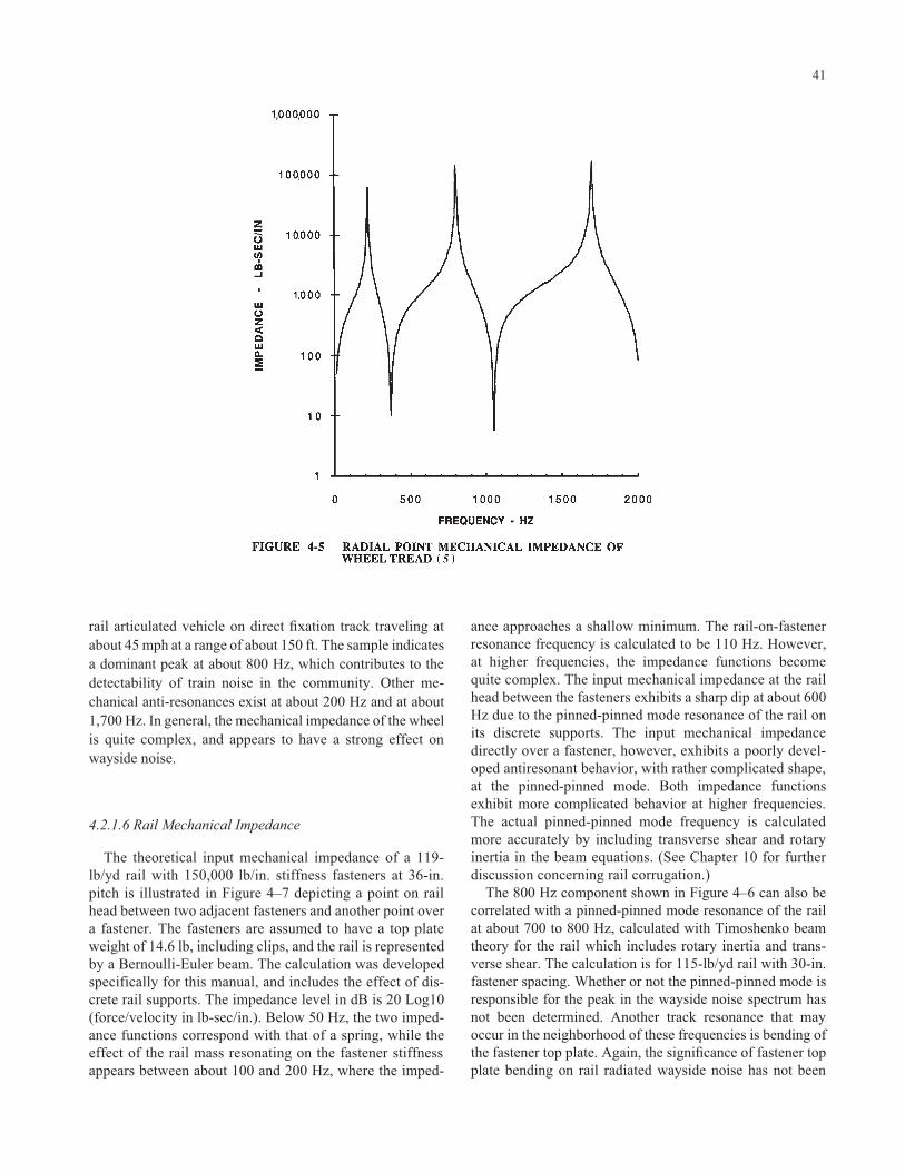
rail articulated vehicle on direct fixation track traveling atabout 45 mph at a range of about 150 ft. The sample indicatesa dominant peak at about 800 Hz, which contributes to thedetectability of train noise in the community. Other me-chanical anti-resonances exist at about 200 Hz and at about1,700 Hz. In general, the mechanical impedance of the wheelis quite complex, and appears to have a strong effect on wayside noise.
4.2.1.6 Rail Mechanical Impedance
The theoretical input mechanical impedance of a 119-lb/yd rail with 150,000 lb/in. stiffness fasteners at 36-in.pitch is illustrated in Figure 4–7 depicting a point on railhead between two adjacent fasteners and another point overa fastener. The fasteners are assumed to have a top plateweight of 14.6 lb, including clips, and the rail is representedby a Bernoulli-Euler beam. The calculation was developedspecifically for this manual, and includes the effect of dis-crete rail supports. The impedance level in dB is 20 Log10(force/velocity in lb-sec/in.). Below 50 Hz, the two imped-ance functions correspond with that of a spring, while theeffect of the rail mass resonating on the fastener stiffnessappears between about 100 and 200 Hz, where the imped-
41
ance approaches a shallow minimum. The rail-on-fastenerresonance frequency is calculated to be 110 Hz. However,at higher frequencies, the impedance functions becomequite complex. The input mechanical impedance at the railhead between the fasteners exhibits a sharp dip at about 600Hz due to the pinned-pinned mode resonance of the rail onits discrete supports. The input mechanical impedancedirectly over a fastener, however, exhibits a poorly devel-oped antiresonant behavior, with rather complicated shape,at the pinned-pinned mode. Both impedance functionsexhibit more complicated behavior at higher frequencies.The actual pinned-pinned mode frequency is calculatedmore accurately by including transverse shear and rotaryinertia in the beam equations. (See Chapter 10 for furtherdiscussion concerning rail corrugation.)
The 800 Hz component shown in Figure 4–6 can also becorrelated with a pinned-pinned mode resonance of the railat about 700 to 800 Hz, calculated with Timoshenko beamtheory for the rail which includes rotary inertia and trans-verse shear. The calculation is for 115-lb/yd rail with 30-in.fastener spacing. Whether or not the pinned-pinned mode isresponsible for the peak in the wayside noise spectrum hasnot been determined. Another track resonance that mayoccur in the neighborhood of these frequencies is bending ofthe fastener top plate. Again, the significance of fastener topplate bending on rail radiated wayside noise has not been

determined. (See the discussion concerning top plate bending in Chapter 10.)
Bending waves will propagate in the rail up to a frequencycorresponding to twice the wavelength of the pinned-pinnedmode wavelength. Between this wavelength and the pinned-pinned mode wavelength, vibration transmission along therail may be inhibited, depending on the rail support dynamiccharacteristics, producing what is termed as the “stop band.”Above the pinned-pinned mode frequency, up to another cut-off frequency, bending waves may propagate freely, result-ing in a “pass band.” The response of the rail and its abilityto radiate noise will be affected by the widths of the stopband. A slight randomness in the support separation may significantly alter the pass and stop band characteristics (9).
One may conclude that at the dominant frequenciesbetween 250 and 1,000 Hz associated with wheel/rail rollingnoise there are extensive possibilities for interaction betweenthe wheel and rail, and that these interactions must be con-sidered when dealing with noise control and rail corrugation.
42
4.2.1.7 Contact Stiffness
Contact stiffness is calculated on the basis of Hertzian con-tact theory, the results of which are presented in Figure 4–8for a 15-in. radius wheel. The contact stiffness does not varygreatly over the range of rail head ball radii, though reducingthe ball radius to 6 in. from about 15 in. would appear toreduce the contact stiffness by about 16%, which, under themost optimistic scenario, would reduce contact forces by atmost 1.5 dB. Note, however, that contact stresses may beincreased as a result of lessened contact area. Optimizing thecontact stiffness would not appear to produce a significantnoise reduction, while setting the ball radius to be compara-ble with that of the wheel (15 in.) would “round out” the con-tact patch, possibly leading to lower wear rates, and, indi-rectly, lower noise. Typical practice, however, is to employa ball radius of about 7 to 10 in. As discussed below, wheeltread concavity due to wear increases the lateral contactpatch dimension, with the result that the contact width maybe comparable with that of a less worn wheel tread on, for

example, rail with ball radius 14 in. Although the rail headmay be optimized for a particular ball radius, wheel treadwear may frustrate maintaining a specific contact widthunless a vigorous wheel truing program is in place.
4.2.1.8 Wheel/Rail Conformity
Increasing conformity of the wheel and rail has been pro-posed by Remington (10) as a noise reduction technique totake advantage of uncorrelated roughnesses between variousparallel paths along the rail in the longitudinal direction. Sig-nificant noise reductions on the order of 3 to 5 dB are pre-dicted for frequencies on the order of 500 Hz. However,increased wheel/rail conformity has been identified as acause of spin-creep corrugation at the Vancouver Skytrain(2), leading to noise. Care should be exercised before adopt-ing high conformity wheel and rail profiles. High wheel/railconformity results from normal wheel tread wear if wheeltruing is not frequently conducted.
4.2.1.9 Noise Radiation
Measurement data suggest that both the wheel and rail aresignificant sources of noise, and both must be considered indeveloping noise control solutions. The acoustic power radi-
43
ated by a wheel can be approximated by the area of the wheelmultiplied by the rms velocity of the wheel surface in a direc-tion normal to the surface, and the specific impedance of air,�c, where � (1.2 kg/m3) is the air density and c is the velocityof propagation of sound (340 m/sec). Other dimensions aregiven in SI units as well. Sound radiation by the rail is usuallymodeled by assuming that the rail is a cylinder of diameterequal to the height of the rail. Noise radiation partitioningbetween the rail and wheel is difficult to quantify accuratelybecause of the closely coupled nature of the wheel and railand their proximity to one another. Even the ties can be con-sidered significant noise radiators. For continuous smoothground rail, much of the theoretical literature suggests that therail is the most significant radiator of noise (5). Numerousexperimental data suggest, however, that wheel-radiatednoise is of similar significance as that of the rail (11,12).
Noise radiation from the wheel and rail is described interms of radiation efficiencies. For a large radiating surface,with dimensions large relative to the wavelength of sound,the radiation efficiency is unity. For a wheel, the radiationefficiency decreases with increasing wavelength above thediameter of the wheel, and, at long wavelengths relative tothe diameter of the wheel, the radiation efficiency decreasesvery rapidly with increasing wavelength. The radiation effi-ciency for the rail is affected by both the velocity of bendingwaves in the rail and by the diameter of the rail. The radia-

tion efficiency becomes negligible if the bending wavevelocity in the rail is less than the acoustic velocity. For thepresent purposes, this effect is ignored. The radiation effi-ciency of a rail may be modeled by a cylinder of diameterequal to the width of the rail. An example of the dependenceof the radiation efficiency on frequency for a 6-in.-diametercylinder in rigid body motion transverse to the rail center ispresented in Figure 4–9. This model indicates that the radia-tion efficiency for a typical rail may be assumed to be unityat frequencies greater than about 1,000 Hz. At lower fre-quencies, the wavelength in air is long with respect to thediameter of the rail, leading to a declining radiation effi-ciency with decreasing frequency. However, noise radiationby the rail is still significant at 500 Hz. For very low fre-quencies, the radiation efficiency is declining as the cube ofthe frequency and as the fourth power of the rail diameter.
4.2.1.10 Directivity
Peters (12) has determined that the radiation pattern forsound radiated by rail vehicles is primarily that of a distribu-tion of dipole radiators. For a dipole radiator, the sound inten-sity across a unit of area normal to the direction of propaga-tion varies as the square of the cosine of the angle between thedirection of maximum radiation and the direction of radiation
44
(13). An example of the angular dependence of sound radia-tion from a dipole source is provided in Figure 4–10. Dipoleradiation is consistent with noise radiation from a wheel, and,for this reason, Peters conjectures that the wheel is the domi-nant radiator of noise. However, much of the noise radiatedby the rail may also be radiated in a dipolar fashion.
An example of the passby signature of a 5-car BART tran-sit train is compared in Figure 4–11 with the predicted passbysignature based on a dipole radiation pattern (14). Theagreement between predicted and measured signature shapeis remarkable, indicating that the dipole model is probablymost appropriate, though slightly underconservative. Thenormalized passby signature of a single Portland Tri-MetLRV traveling on ballast-and-tie track at about 35 mph iscompared in Figure 4–12 with predictions based on mono-pole and dipole radiation patterns. In this case, the passbysignature falls midway on a decibel scale between that pre-dicted for monopole and dipole sources. The Tri-Met vehiclehas Bochum resilient wheels which may affect the radiationof noise. In both cases the dipole model underpredicts theshoulders of the passby signature. From a practical stand-point, the discrepancy is not particularly important for longtrains. The data shown for the Tri-Met vehicle are for a sin-gle vehicle with three trucks, and may not be representativeof the fleet or other light rail vehicles.

The dipole radiation pattern, or directivity factor, has aneffect on computation of energy-averaged sound levels, ornoise exposure levels. Maximum sound levels occurringduring train passage are not strongly affected, though dif-ferences on the order of 1 dB at distances beyond one trainlength from the track may exist between the dipole andmonopole model. The effect on attenuation with distance isnot large, but there may be a significant effect when basing
45
calculations on sound power radiated by the wheels andrails. Finally, if traction power equipment or air condition-ing noise is included, the monopole radiation model maybecome more significant. Assuming a monopole sourcecharacteristic will result in a conservative estimate ofenergy-averaged sound levels such as the Equivalent SoundLevel (Leq) or Day-Night Sound Level (Ldn), though the margin is limited to 1 dB.

4.2.1.11 Attenuation with Distance
The sound radiated over an open field from a transit trainattenuates with distance from the track for two main reasons,the effects of ground and atmospheric absorption notwith-standing: Geometric Attenuation or Spreading Loss, andExcess Attenuation. Geometric spreading loss is due toenergy dispersion into three dimensions and is the most sig-nificant. From a point source, the maximum sound levelattenuates at a rate of 6 dB per doubling of distance. For aline source, such as a train, and a receiver within about 1 ⁄2train length from the track, the maximum sound level willattenuate at a rate of 3 dB per doubling of distance. At largerdistances, the finite length of the train causes the maximumsound level to attenuate at a rate greater than 3 dB per dou-bling of distance. The equivalent level, Leq, or the Day-NightLevel, Ldn, will attenuate at 3 dB per doubling of distance dueto geometric spreading, regardless of train length. Excessattenuation is due to sound energy absorption by the ground
46
and the complex interference effects related to the direct andground reflected waves.
4.2.1.11.1 Attenuation Due to Geometric Spreading
The maximum passby sound pressure level for dipolesource characteristics in the absence of excess attenuationcan be represented as
For a monopole source, the maximum sound level as a func-tion of distance, R, from the train is
L re cQ WR
M Mmax dB Pascal Log20 10
42 94μ ρ
πα( ) = ′⎡
⎣⎢⎤⎦⎥
+
L re
cQ WR
D D
max
sin
dB Pascal
Log
20
10 34 4
2 2 94
μ
ρπ
α α
( )
= ′ + ( ){ }⎡⎣⎢
⎤⎦⎥
+

The angle, �, is given by
W D is the dipole sound power per unit train length, W M is themonopole sound power per unit train length, both in Wattsper meter, L is the train length in meters, and R is the distancefrom the track center in meters. The product of the densityand acoustic velocity, �c, is the specific impedance of air,equal to 407 rayls (kg/m2/sec). (The SI system of units is pre-ferred for these types of computations.) QM and QD are direc-tivity factors associated with radiation patterns in the verti-cal plane transverse to the rail. For practical problems, thedirectivity factors QM and QD can be assumed to be uniformwith respect to the angle above the horizontal plane, thoughthis assumption is open to further investigation. The direc-tivity factors are 1 for a fully absorptive ground surface (bal-lasted track with grassy embankment), and 2 to 4 for a fullyreflective ground plane (embedded track), ignoring interfer-ence effects. If most of the noise is radiated by the rail, thenQ would be 4 for a concrete invert with direct fixation fas-teners, yet 1 for ballast-and-tie track, a not insignificant dif-ference of 6 dB, and only slightly greater than the 5 dB dif-ference often observed between noise levels from aerialstructure and ballasted track.
In practice, the sound level is measured at a reference dis-tance of, perhaps, 15 m, or 50 ft, and sound levels at other
α = ⎛⎝
⎞⎠arctan L
R2
47
distances are expressed as ratios of distances, speeds, and soon. In this case, the acoustic impedance, �c, and the soundpower per unit track length cancel each other out. A variantof this approach is to measure the single-event noise expo-sure level, SENEL, or simply the SEL, for a train, and, fromthat, determine the sound power per unit length of train,assuming either a dipole or monopole distribution of sources.The SEL for a train passby is 10 times the logarithm of thetime integral of the sound pressure squared, relative to thesquare of the reference pressure. For dipolar noise character-istics, the SEL is
The integral is with respect to time in seconds and v is thetrain speed in m/sec. For a monopole source, the SEL is
The total sound power for the train is WL. A factor of 3 ⁄4appears in the expression for the dipole source. Thus, the sin-gle event level, SEL, for a dipole source is 1.25 dB less thanthe SEL for a monopole source of equivalent sound powerper unit length.
SEL dB Log( ) = ′⎡⎣⎢
⎤⎦⎥
10410
02
ρcQW Lp Rv
M
SEL dB Log Log( ) =( )⎡
⎣⎢⎢
⎤
⎦⎥⎥
= ′⎡⎣⎢
⎤⎦⎥− ∞
+ ∞
∫10 10 34 410
2
02 10
02
p tp
dt cQW Lp Rv
Dρ

The maximum sound level can be expressed in terms ofthe SEL directly, given the train length and distance (15). Forthe dipole distribution, the expression is
For the monopole source distribution
The maximum sound level may be expressed in terms ofthe reference SELs presented in the FTA guidance manualfor environmental assessment (16). The reference SEL lev-els are referenced to 50 ft from track center and 50 mph trainspeed. Dipole source distributions are assumed for rail cars,assuming that the noise is primarily wheel/rail, for which themaximum levels are then given by
L re Pa + VL
+
max dB SEL Log
Log
20 10
10 2
10
10
μπ
α
( ) = ⎡⎣⎢
⎤⎦⎥
[ ]
L re Pa + VL
+ +
max
sin
dB SEL Log
Log
20 10
10 2 2
10
10
μπ
α α
( ) = ⎡⎣⎢
⎤⎦⎥
( )[ ]
48
For the monopole distribution, the maximum level is
For train length long relative to receiver distance, �approaches π/2, sin(2�) approaches 0, and the expressionsfor the maximum passby levels in terms of the SELs becomethe same for the dipole and monopole sources.
The attenuation of wayside maximum noise levels as afunction of distance from a train with dipole noise sources isillustrated in Figure 4–13 (17). At distances close to the train,
L re Pa +
L +
max
.
dB SEL Log S mphmph
Log ftft
Log
ref20 1050
1050
10 2 3 3
10
10
μ
α
( ) = ( )( )
⎡⎣⎢
⎤⎦⎥
−( )⎡
⎣⎢⎤⎦⎥
[ ] −
L re Pa +
+ +
max
sin .
dB SEL Log S mphmph
Log L ftft
Log
ref20 1050
1050
10 2 2 3 3
10
10
μ
α α
( ) = ( )( )
⎡⎣⎢
⎤⎦⎥
−( )⎡
⎣⎢⎤⎦⎥
( )[ ] −

that is, within one train length, the attenuation versus dis-tance is about 3 dB per doubling of distance, correspondingto a line source. At larger distances, the train begins to looklike a point source, or at least a source of finite length, andthe attenuation due to geometric spreading increases to about6 dB per doubling of distance. The distance at which theattenuation versus distance goes from a line source characterto a point source character is determined by whether or notthe train is modeled as a dipole or monopole source. Withina distance of 2/π times the average truck-to-truck spacing,the short-period maximum noise level will be controlled byindividual trucks, and the attenuation versus distance curvesgiven in Figure 4–13 will not be representative at distancesless than about 15 to 25 ft from the track. Normaltrain/receiver distances are greater than 25 ft, though thereexist urban situations with transit structures immediatelyadjacent to residential structures.
The calculation of energy equivalent sound levels (Leq) asa function of distance will depend on source characteristics,train speed, length, and so on The SEL, Leq, and Ldn attenuateat a rate of 3 dB per doubling of distance in the absence ofground effects, shielding by structures, or atmosphericabsorption, because of the linear nature of the source whenaveraged over time. This particularly simple result leads togreat simplification in predicting transit system noise, asopposed to predicting the attenuation with distance of maxi-mum sound levels.
4.2.1.11.2 Excess Attenuation
Where ground effects are to be included, a commonassumption is that the single-event sound exposure level,SEL, or equivalent level, Ldn, attenuate at a rate of 4.5 dB perdoubling of distance from the track. In this case, the maxi-mum sound level may be calculated from the SEL using theformulas given above for 3 dB per doubling of distance towithin an accuracy of about 1 ⁄2 dB. This surprising result isdue to the fact that the maximum level will also decline byabout 1.5 dB per doubling of distance in addition to the geo-metric spreading loss. More refined estimates of groundeffect are provided in the FTA Guidance Manual (18).
The sound power per unit length cannot be reliably esti-mated from maximum sound levels and assuming a 4.5 dBattenuation per doubling of distance. A more physically real-istic model would be required. On the other hand, within 50ft from the track, sound absorption provided by the groundmay not be significant, and a 3 dB attenuation per doublingof distance would probably be appropriate for most closereceivers. In fact, with respect to design of noise controltreatments, relying on excess attenuation to control noiseimpacts at receivers within about 100 ft from the track isprobably not appropriate, since most receiver windows arewell above the ground, and second story windows would notbenefit at all. This is doubly true for aerial structure track.
49
Judgment must be exercised in determining whether toinclude excess attenuation.
Atmospheric absorption is usually not significant withinabout 500 to 1,000 ft of the source. The excess attenuation ata frequency of 500 Hz and at a distance of 1,000 ft from thesource is less than a decibel. Noise from rail transit systemsis usually insignificant beyond about 500 ft from the track.For this reason, atmospheric absorption is not included in themodeling of rail transit noise versus distance. However, theremay exist certain pathological situations where noise com-plaints are received from residents located at considerabledistance from the track. Examples include low-frequencynoise radiation from bridge structures, for which atmosphericabsorption is not significant again. Rail corrugation maycause particularly raucous noise which may be objectionableto receivers at distances in excess of 500 or 1,000 Hz,depending on the type of community. In these cases, atmos-pheric absorption should be included in the consideration ofsound propagation. However, one must add the effects oftemperature inversions and wind gradients, both of which arediscussed in the preceding chapter.
4.2.1.11.3 Combined Geometric Spreading andExcess Attenuation
The following formula can be used to compute the SEL ata receiver for a reference SELref given for a reference distanceand speed.
Kspeed � 30 dB/Decade speed
G � 0.5 (Soft Ground)
� 0 (Hard Ground)
The speed dependence, Kspeed, is given as 30 dB per decadespeed for the maximum sound level, which is reasonablyaccurate for wheel/rail noise calculations. In the above, adecade change in speed is an increase in speed by a factor often. Thus, A-weighted noise levels will tend to increaseapproximately as 30 Log10(speed). Ten decibels are sub-tracted to account for the vehicle passby time duration, sothat the actual variation of SEL as a function of train speedwould be about 20 dB per decade speed. A lower speeddependence of 27 dB per decade speed has been measuredfor passby maximum sound levels by the author for vehicleswith Bochum wheels. Still lower speed dependence might be
SEL SEL Log
Log
ref speedref
refref
= K VV
DD
+ −( ) ⎛⎝⎜
⎞⎠⎟
− +( ) ⎛⎝⎜
⎞⎠⎟
10
1 10
10
G

obtained for vehicles with minor wheel flats, due to the speeddependence of wheel flat noise on train speed, as discussedbelow. The excess attenuation factor, G, is 0.5 if 4.5 dBattenuation per doubling of distance is assumed for “soft”ground, and is identically zero if a 3 dB attenuation per dou-bling of distance over “hard” ground or from aerial structuresis assumed. This usage is consistent with the FTA GuidanceManual.
4.2.2 Excessive Rolling Noise
Excessive rolling noise without corrugation is producedby abnormally rough rails and wheels. The roughness may ormay not be apparent to the eye, and may include visible pits,spalls, and other imperfections in the running surface. Poordefinition of the contact wear strip or irregular width con-tributes to excessive rolling noise. The rail roughness spec-trum illustrated in Figure 4–4 for the MBTA is an exampleof rough rail. Where excessive rolling noise is suspected, aninspection of the track and wheels may indicate pits andspalls and generally worn running surfaces. A quantitativemeasurement of rail roughness using a profilometer can beused to measure the roughness amplitude as a function ofwavelength or wavenumber. Noise reductions achieved byrail grinding would confirm the existence of excessivelyrough rail.
Excessive rolling noise due to rail and wheel roughnesswith insufficient amplitude to produce contact separation isdescribable by the standard linear model of parallel mechan-ical impedances described above. In this case, the excessiverolling noise level varies linearly with roughness level. Ifsmooth undulations of the rail surface are of sufficient am-plitude, contact separation may occur, contributing to visi-ble wear. In these cases, impact noise may occur, which isdiscussed below in the next section.
The radiation and attenuation with distance of noise asdescribed above for normal rolling noise also applies toexcessive rolling noise. The noise radiation should conformto that of a distribution of dipole sources.
4.2.3 Impact Noise from Rail Imperfections,Joints, and Wheel Flats
Impact noise is a special type of wheel/rail noise whichoccurs at tangent track with high-amplitude roughness, railjoints, rail defects, or other discontinuities in the rail runningsurface, and wheel flats. Remington provides a summary ofimpact noise generation (5), which involves nonlinearwheel/rail interaction due to contact separation, and isclosely related to impact noise generation theory at specialtrackwork. I. L. Ver (19) categorizes impact noise by type ofrail irregularity, train direction, and speed. The theory pre-sented below is based on Ver’s discussion.
50
4.2.3.1 Smooth Irregularity
A smooth irregularity may produce an impact if the trainspeed exceeds the critical velocity defined as
Here, g is the acceleration of gravity, M is the total vehi-cle weight supported by the wheel, m is the wheel mass, � isthe rail mass per unit length, and y is the rail longitudinal pro-file. The parameter, �, is related to the rail support modulus,and rail section by
The rail need not contain a visual discontinuity to producean impact, because even a smooth undulation in the rail pro-file may cause contact separation. For an 880-lb wheel, 100lb/yd rail, rail support modulus of 8.5�105 lb/ft2, and rough-ness wavelength of 1.3 ft and amplitude of 0.08 in., the crit-ical velocity at which rail separation may be expected isabout 60 mph. The critical velocity is about 30 mph for ashort wavelength of perhaps 2 in. and amplitude 0.05 in. (cor-responding to very severe short pitch rail corrugation).(Impact theory is directly relevant to contact separation atcorrugated rail.) The theory suggests that contact separationwill occur at lower train speeds for low wheel loads than forhigh wheel loads. Thus, light weight transit vehicles aremore prone to dynamic contact unloading, lateral slip, and,perhaps, short pitch corrugation, than heavy freight vehicles.
4.2.3.2 Level and Decreasing Elevation RailJoints and Wheel Flats
“Level rail” joints are characterized by rail ends at equalrunning surface elevation, but separated by a distance, w. Adecreasing elevation, or “step-down” joint, is characterizedby an elevation drop, h. Wheel flats are characterized by thesame distance, h, which is the defect depth of the flat relativeto the normal rolling surface of the wheel. A rolling wheelmust traverse the gap or wheel flat, and there exists a criticalvelocity above which the wheel loses contact with the rail. Inthis case, the critical velocity is given by
where a is the wheel radius. The gap width, step-downheight, or flat depth do not significantly affect the criticalvelocity, though these parameters do strongly determine theimpact velocity of the rail and wheel, which is directlyrelated to the peak sound pressure produced by the impact.
V ag Mm
mCE = +⎛
⎝⎞⎠ +⎛⎝⎜
⎞⎠⎟
⎡⎣⎢
⎤⎦⎥
1 12
1 2
ρβ /
β μ= ⎡⎣⎢
⎤⎦⎥4
1 4
EI
/
Vg M
d y/dxm
CE =+⎛
⎝⎞⎠
+⎛⎝⎜
⎞⎠⎟
⎡
⎣
⎢⎢⎢
⎤
⎦
⎥⎥⎥
11
22 2
1 2
mρ
β/

At high speed, the noise produced by a wheel flat willdecrease with increasing train speed, and, at sufficiently highspeed, the noise due to a relatively small single flat maybecome imperceptible above the normal rolling noise. Evenwith large flats, the wheel will appear to drop on the flat atlow speed, but not drop on the flat at high speed (20). Simi-larly, a wheel traversing a gap will produce less noise at sufficiently high speed than at lower speeds.
4.2.3.3 Step-Up Rail Joints
Step-up rail joints are the most serious of impact noise pro-ducing rail joints, because there is no critical speed abovewhich the peak sound pressure ceases to rise with increasingspeed. An impact is always generated, and the impact veloc-ity is directly related to speed. As a result, the impact noisefrom step-up joints would never be masked by normal rollingnoise as might occur for step-down joints or wheel flats. Therail impulse, meq�V, is then given by
where meq is an equivalent rail mass determined by its bendingstiffness and mass per unit length. For typical rail supports andbending moduli, the equivalent mass is approximately 40% ofthe mass contained within a 1-m-long section of rail.
4.2.3.4 Summary of Impact Noise
The main points of the above discussion are listed by I. L.Ver, et al. as
1) The step-up joint is the most serious rail joint withrespect to producing impact noise, because there is nocritical speed above which no increase in noise levelmay be expected with increasing speed.
2) Step-down joints and wheel flats cause separation ofthe wheel from the rail above a critical velocity. Belowthe critical velocity, sound pressure levels may beexpected to increase with increasing train speed.Above the critical velocity, no increase in noise levelmay be expected with increasing train speed, and the impact noise may be masked by rolling noise at sufficiently high speed.
3) Below critical speed, step-up joints, step-down joints,and wheel flats of the same height generate similarpeak sound levels for a given rail head elevation dif-ference or flat depth, h. The peak sound pressureincreases with increasing wheel load and height.
4) Smooth irregularities may produce impact noise due tocontact separation above a critical speed. The criticalspeed is less at lower axle loads than at higher axleloads, and increases with increasing radius of curvatureof the irregularity.
)m V = Vm haeq eqΔ 2
51
5) Rail support resilience increases the critical speed rel-ative to rigid rail condition. For typical wheels and railsupport conditions, the increase is by a factor of tworelative to rigid track.
6) The impact noise decreases with increasing wheelradius and increases with increasing wheel mass.These offsetting parameters may cancel any noisereduction which might be expected by increasingwheel radius.
Modern transit systems employing continuous welded railand trued wheels will likely not be concerned with impactnoise generated by rail joints, though there will remainimpact noise generated by rough rail, wheel flats, switchfrogs, and crossover diamonds. Further, older systems whichemploy jointed rail at steel elevated structures must be con-cerned with rail joint condition and maintenance, and all sys-tems must be concerned with rail grinding and wheel truingto eliminate associated impact noise.
4.2.4 Corrugated Rail Noise
Rail corrugation causes excessive rolling noise of a par-ticularly harsh character and of very high level. The terms“roaring rail” or “wheel howl” or “wheel/rail howl” are typical descriptors of noise produced by corrugated rail.
4.2.4.1 Characterization
If rail corrugation exists, the passby noise level will behigh compared to that of normal rolling noise, and the spec-trum will contain discrete frequency components and associ-ated harmonics clearly revealed with 1/3-octave or narrowband analyses of the passby or interior noise. An example ofa 1/3-octave band spectrum of noise due to trains travelingon corrugated direct fixation track is presented in Figure4–14. In this case, the existence of corrugation is revealed bythe spectral peak at the corrugation frequency, which occursat about 500 Hz. A second harmonic is also visible at 1,000Hz. In this example, the trains had aluminum centeredwheels, and were typically four to seven cars in length. Also,at this location, train speeds were uniform at about 54 mph,regulated under computer control. Thus, the corrugationwavelength was clearly defined, not being destroyed by ran-dom train speed variation.
Narrow band analyses of noise may reveal corrugationwavelengths or other periodic patterns in the rail running sur-face. For example, noise collected at multiple train speeds foroperation on the same corrugated rail will show a linear vari-ation of spectral peak frequencies with train speed. At highspeeds, contact separation might occur, and the discrete fre-quency component due to rail corrugation may broaden, forwhich a less easily identified pure tone component might beexpected. Narrowband analyses of car interior noise with sub-stantial wheel/rail howl are presented in Figures 4–15 and

4–16 for train speeds 40 and 66 mph, respectively. The datawere recorded at a severely corrugated section of track and ata section of recently ground track with grinding pattern in theBART transbay tube. The corrugation frequency is clearlyobservable at about 400 and 600 Hz in the 66 mph data, whileat 40 mph, the peaks are shifted downward to 250 and 375 Hz.These peaks are absent in the data shown for ground rail.(However, a grinding pattern caused peaks to occur at about1,400 and 900 Hz, respectively, at 66 and 40 mph.)
A mechanical resonance, such as that produced by reso-nance of the wheel set or track, will produce noise with spec-tral components whose frequencies do not vary with trainspeed. Thus, if spectral analyses for various speeds indicateno change in the peak frequency with varying train speed, thecause of the noise is likely not rail corrugation or any otherperiodic pattern in the rail. On the other hand, mechanicalresonances will be excited by rail corrugation, and the ampli-tude of the resulting noise may vary substantially, dependingon the relationship between corrugation frequency and themechanical resonance frequency.
Machine bluing, magnaflux dye, or lamp black spread overthe rail running surface may be helpful in identifying corru-gation waves. The corrugation wavelength may be measured
52
and compared with noise spectra obtained at the same loca-tion to determine if corrugation is a significant source of thenoise. A rail profilometer can be used for evaluation of wearrates and grinding effectiveness.
4.2.4.2 Wheel/Rail Interaction at Corrugated Rail
The interaction between the wheel and rail in the presenceof corrugation may be considerably more complex than thatdescribed by the standard linear model used to describe nor-mal rolling noise. One principal reason is that contact sepa-ration may occur as a result of the inability of the wheel tofollow the corrugated rail’s vertical profile. For example, theforce required to displace the center of gravity of an 800-lbwheel by 0.005 in. is about 10,000 lb, roughly similar to thewheel static load, assuming the wheel to be rigid. Contactpatch stiffness, rail compliance, and wheel resonances willmodify this estimate. Higher amplitude corrugation wouldproduce higher dynamic loads, except that the static loadplaces a limit on the maximum dynamic load that can occurduring an unloading cycle. Thus, there must be a contact sep-aration at higher amplitudes. Corrugations of even moderateamplitude can be expected to produce contact separation, or

at least an increased propensity for lateral dynamic slipbetween the wheel and rail due to unloading of the contactpatch. Periodic lateral slip can then lead to additional peri-odic wear and corrugation, producing regenerative wear.
Figure 4–17 illustrates 1/3-octave band noise levels withand without corrugation. In these cases, a corrugation ampli-tude of merely 0.002 in. produces noise at a discrete fre-quency in the 630 Hz octave band roughly 8 to 10 dB higherrelative to neighboring bands. A larger amplitude of 0.004in. produces a broader spectral peak between 500 and 1,000Hz. The actual conditions under which these data were takenare not known, but the broader bandwidth associated withcorrugation amplitude of 0.004 in. versus an amplitude of0.002 in. suggests that the noise generation process might bedifferent between these two sets of data. Contact separationis a possible mechanism by which this might be broughtabout. More importantly, the data indicate that only a rela-tively small corrugation amplitude is sufficient to produce asubstantial increase in wayside noise levels.
In the presence of lateral slip or contact separation, theequality of lateral dynamic displacement of the wheel andrail is relaxed. A practical result is that the wheel’s lateralvibration modes may be easily excited, with the result thatthe ratio of noise energy radiated by the wheel relative to that
53
radiated by the rail may be more with corrugated rail thanwith uncorrugated rail.
Modeling of wheel/rail noise in the presence of contact sep-aration or lateral dynamic slip is complicated by the nonlinear-ity of the contact vertical load versus vertical displacement, andlateral slip versus vertical displacement. A realistic theoreticalmodel requires time-domain integration of the equations ofmotion, and simple modeling with the usual linear theories maybe inadequate. For example, accounting for the nonlinearity ofthe Hertzian contact patch stiffness as a function of dynamicload indicates that dynamic contact forces may be higher thanthose predicted on the basis of constant contact patch stiffness,exceeding the wheel static load for rail roughness amplitudeson the order of 0.001 in. and trains traveling at close 80 or 90mph, further encouraging lateral slip during unloading (21),which has been identified with the corrugation process (22).
To summarize, rail corrugation is more difficult to controlat rail transit systems than at railroads because of lighter con-tact patch loads at rail transit systems. The uniformity of tran-sit vehicle types and speeds prevents randomization ofwheel/rail force signatures, which simply exacerbates thecorrugation process. Thus, for rail transit systems withlightly loaded rails, the importance of maintaining railsmoothness is greater than at heavy freight systems. Rail cor-

rugation is the principal cause of excessive noise levels atmany transit systems, and controlling rail corrugation is keyto rail transit system noise control.
Rail corrugation processes and methods of control are discussed in greater detail in the chapter on rail corrugation.
4.3 CURVING NOISE
Curving noise includes both normal rolling noise, whichalso occurs at tangent track, and noise unique to curving,resulting form lateral slip of the wheel tread across the railhead. Noise due to lateral slip is often manifested as an intense,sustained squeal, caused by the negative damping associatedwith the friction versus creep characteristic. Normal rollingnoise will not be significant at short radius curves, especiallyin the presence of wheel squeal, due to low train speed, and athigh-speed curves, rolling noise may be treated in much thesame manner as for tangent track. This section is directedentirely to curving noise due to lateral slip generated noise.
There appear to be two types of curving noise. The first and most prevalent is wheel squeal cause by sustained nonlin-ear lateral oscillation of the wheel. The second, less obvious,and less common, is wheel howl, which may be due to the res-onant but unsaturated response of the wheel to dynamic lateral
54
creep forces. There are reasons to believe that these types ofcurving noise are separate phenomena: (1) they do not soundthe same; (2) wheel howl at curves increases with train speed,while conventional wheel squeal may disappear with suffi-ciently high train speed; and (3) wheel/rail howl may be closelyassociated with short pitch corrugation at curves. Of these twotypes of curving noise, wheel squeal is the more prevalent,while wheel howl may be limited to lightly damped aluminumcentered wheels such as used at BART. In fact, wheel howlmay be unique to BART, because BART is the only transit sys-tem employing rigid aluminum centered wheels.
4.3.1 Wheel Squeal
Wheel squeal is one of the most noticeable types of noise pro-duced by rail transit systems, and can be very significant at bothshort and long radius curves. At embedded track curves of lightrail systems, pedestrians and patrons may be in close proximityto the vehicle and thus be subjected to high squeal noise. Anexample is the Government Center Curve at the Boston GreenLine, where transit patrons are necessarily within a few ft of thetrack within an enclosed underground area, without the benefitof shielding by a platform. At older transit systems where win-dows may be left open during passage through subways, squeal

can be discomforting to patrons inside the vehicle, especially ifno substantial sound absorption exists in the subway. Even inmodern transit vehicles, inadequate door seals may allow expo-sure of patrons to high levels of squeal noise in tunnels.
Wheel squeal may be intermittent due to varying tribolog-ical properties, varying amounts of rail surface contaminants,or curving dynamics of the vehicle and rail. An example ofthe time dependence of wheel squeal is provided in Figure4–18. In this case, the squeal is produced by a Portland Tri-Met vehicle with resilient wheels on an 87-ft radius embed-ded track curve. The squeal noise level varies considerablyover time. On damp mornings, wheel squeal may be nonex-istent for all or most of the curve negotiation. The maximumlevel of squeal noise is relatively insensitive to duration andfrequency of occurrence.
Maximum and energy-averaged 1/3-octave band spectraof the wheel squeal illustrated in Figure 4–18 for the Tri-Metvehicle are provided in Figure 4–19. These data include fun-damental squeal frequencies in the 500, 1,250, and 3,150 Hz1/3-octave bands. The high levels of noise at discrete squealfrequencies indicate the high level of perceptibility andpotential for annoyance. The maximum levels shown are themaximum observed 1/3-octave noise levels occurring duringcurve negotiation, and may not have occurred simultane-
55
ously. The lower levels are the energy-averaged, or rms,sound levels occurring during curving. In this example, thereexists considerable disparity between the maximum soundlevel and energy-averaged sound level, caused by the intermittency of the squeal.
Figure 4–20 illustrates the narrowband frequency spectrumof wheel squeal recorded at BART during the Car 107 tests in1971 at a 540-ft radius curve. These data include sustainedsqueal at frequencies above 1,000 Hz and low train speed of 18mph. At a train speed of 35 mph, the squeal above about 1,000Hz is absent. The inhibition of squeal at higher train speeds isa feature of wheel squeal that is due to reduced negative damping at higher lateral slip velocities, as discussed below.
4.3.1.1 Causes of Wheel Squeal
Three types of stick-slip motion have been postulated forproducing wheel squeal noise:
1) Longitudinal stick-slip,2) Flange contact with the gauge face, and3) Stick-slip due to lateral creep across the rail head
caused by nonzero angle of attack of the wheel, in turnproduced by the finite wheel base of the truck.

56

Longitudinal stick-slip is due to the different translationvelocities between the high and low rail wheels. Wheel taperis sufficient to compensate for differential slip at curves inexcess of about 2,000-ft radius, though shorter radii may beaccommodated by profile grinding of the rail head. Further,Rudd reports that elastic compression of the inner wheel andextension of the outer wheel tread under torque can compen-sate for the wheel differential velocities, and, further, thattrucks with independently driven wheels also squeal (23).Therefore, longitudinal slip is not considered to be a cause ofwheel squeal.
Flange rubbing is due to contact between the flange andhigh rail and has been considered by many as a cause ofwheel squeal. However, lubrication of the flange does notalways eliminate wheel squeal, and (according to Rudd)Stappenbeck reports that the low rail wheel has been identi-fied as the source of wheel squeal, which does not ordinarilyundergo flange rubbing (24). These observations suggest thatflange contact is not a significant cause of squeal. Howeverobservations of noise at the MBTA Green Line indicate thatsubstantial squeal is produced by the unrestrained high rail
57
wheels at a short radius curve, and little or none by the lowrail restrained wheels. Substantial flange rubbing occurs atthe high rail leading wheel, suggesting that flange rubbingcontributes to squeal. Further, it is not clear whether the lead-ing or trailing wheel is the source, and the trailing wheelflange does not contact the gauge face. Other observations atthe MBTA Red Line indicate that squeal occurs at points ofrepeated flange contact with the high rail, though, in thiscase, determining whether the high or low rail wheels are thesources of squeal was not possible. Flange lubrication is usedto reduce rail wear and noise at curves, but the noise re-duction observed with flange lubrication may be due tomigration of lubricant to the rail running surface.
Lateral slip of the tread running surface across the railhead is the most probable cause of wheel squeal, and ismost tractable from a theoretical point of view. Eventhough flange contact is often observed at sections of trackwhere squeal occurs, such as at the MBTA, the squeal maybe due entirely to lateral slip across the rail head. The lat-eral slip theory of wheel squeal is discussed more fullybelow.

4.3.1.2 Lateral Slip Model
Figure 4–21 illustrates the geometry of curve negotiationby a transit vehicle truck as described in the literature. Asillustrated, lateral slip across the rail head is necessitated bythe finite wheel base, B, of the truck, and the radius of cur-vature of the rail, where no longitudinal compliance exists inthe axle suspension. However, this curving diagram is notrealistic of actual performance. Figure 4–22 illustrates thecrabbing of a truck under actual conditions (25). In this case,the leading axle of the truck rides toward the outside of thecurve, limited only by flange contact of the high rail wheelagainst the gauge face of the rail. The trailing axle, however,travels between the high and low rail, and the low rail wheelflange may, in fact, be in contact with the low rail gauge face.The result is a reduction of creep angle at the trailing axle,but an increase of creep angle at the leading axle. Gaugewidening would only increase the actual creep angle underthese circumstances. Moreover, with severe creep angle,
58
flange rubbing at the high rail occurs, contributing to wear.This crabbing condition is particularly observable at theMBTA Green Line Government Center Station curve.
The theory of stick-slip oscillation is presented below insome detail in an attempt to clarify the literature. Figure 4–23is a schematic of the wheel and rail system, for which vari-ous parameters are defined. The most useful way of thinkingabout squeal is to consider the problem from the center ofgravity of the wheel, and think of the rail as slipping beneaththe tire in the lateral direction at an average slip velocity, V.The deflection of the tire at the contact point, relative to thecenter of the tire, is represented by U. The velocity of the tirerelative to the center of the wheel is then dU/dt. Then, thetotal creep velocity of the tire relative to the rail head is V�dU/dt. If the rolling velocity is defined as S, then the totalcreep is defined as
ξ = −V dUdt

and the average creep for a lateral slip velocity, V, is
The friction coefficient, µ, is assumed to be entirely a func-tion of the total creep, �.
The equation of motion is obtained by setting the acceler-ation of the wheel tread equal to the sum of the forces actingon the tread, which includes the forces due to the stiffness ofthe wheel, the internal damping of the wheel, and the frictionforce, µW, where W is the vertical contact load
The friction coefficient can be expanded about the averagecreep, �0:
μ μ ξ μξ
ξ ξξ
= ( ) + −( ) +0 0 00
dd
. . .
m d Udt
kU c dUdt
W2
= − − + μ
ξ0 = VS
59
Now define the slope of the friction-creep function, µ, as
Defining the deflection of the tread as the sum of a steadystate deflection, U0 � µ0W, and a dynamic component, u, sothat U � U0 � u, the dynamic component of the creep can beexpressed as
Then, the equation of motion becomes
The solution of this equation is
u u e ei k
m mc v W
S mc v W
S=± − +⎛
⎝⎞⎠
⎡⎣⎢
⎤⎦⎥
− +⎛⎝
⎞⎠
0
14
12
1 2/
m d udt
c v WS
dudt
ku2
2 0+ +⎡⎣⎢
⎤⎦⎥
+ =
ξ ξ− = − = −01 1S
dUdt S
dudt
v dd
= μξ ξ0

Thus, exponential growth of the solution occurs if theslope, �, of the friction-creep curve is sufficiently negative toovercome the internal dissipation, c.
4.3.1.3 Loss Factor Due to Stick-Slip
The internal damping and negative damping due to stick-slip are described by Rudd in terms of loss factors (26).
The combined loss factor for the wheel vibration in theaxial direction is
� � �int – �ss
where�int � internal loss factor
� c/m�ss � Loss factor due to stick-slip
� ��W/mSm � modal mass � radian frequency
� (k/m)1/2
60
If the slope, v, of the friction coefficient versus lateralcreep, is negative, then the loss factor due to stick-slip is pos-itive. If the loss factor due to stick-slip is large enough, thecombined loss factors due to stick-slip and internal energydissipation will be negative, resulting in amplification ofvibration at a modal frequency, as described above. Themodal mass is assumed to be about 1 ⁄3 of the wheel mass,given in a consistent system of units.
The loss factor due to stick-slip is inversely proportionalto the rolling velocity of the wheel, because the creep func-tion is independent of rolling velocity (the creep is equal tothe ratio of the slip velocity and rolling velocity). Thus,wheel squeal may be expected to cease above a certain veloc-ity speed where the loss factor due to stick-slip is not suffi-cient to overcome the loss factor due to internal damping.The form of the friction versus creep used by Rudd is illustrated in Figure 4–24 and is given by
μ μ ξξ
ξ ξ= −( )max exp /m
1 m

Here, �m, is the value of � at maximum friction coefficient,µmax. At a creep angle of about 0.009 radians (0.5 deg), thefriction coefficient reaches a maximum value of about 0.4.The corresponding slope of the friction versus creep curve isillustrated in Figure 4–25. Above the maximum frictionpoint, the slope becomes negative, and unstable oscillationsmay occur, though the occurrence still depends on the mag-nitude of the slope. Below the maximum friction point the curve has positive slope, and thus would not producestick-slip oscillation.
For a wheel base of 7.5 ft, squeal would not be expectedfor curve radii greater than 410 to 830 ft, the lower limitbeing achieved when there is no gauge relief. As illustratedabove, gauge widening increases the creep angle for the sameradius of curvature. A typical assumption is that squeal doesnot occur for curves with radii greater than about 700 ft, corresponding to a creep rate given by
� � 0.7B/R
whereB � wheel baseR � curve radius
4.3.1.4 Effect of Internal Loss Factor
The internal loss factor required to overcome the negativefriction due to stick-slip can be estimated by equating the loss
61
factor due to internal damping to the absolute value of theloss factor for stick-slip. In this case, the loss factor varies asa function of curve radius due to varying crab angle, or creep,and train speed, as illustrated in Figure 4–26. Two curves areshown for vehicle lateral accelerations of 3% and 15% ofearth’s gravitational acceleration. The lateral acceleration isdetermined from the forward velocity of the vehicle andcurve radius. For example, the typical speed of a BART railtransit vehicle in a 540-ft radius curve is about 35 mph, cor-responding to a lateral acceleration of about 15% of gravity.At high train speed and lateral acceleration, the minimumloss factor due to stick-slip is about 20%. At low speed, cor-responding to lateral acceleration of 3%, the loss factor isconsiderably higher.
In practice, wheel squeal is usually inhibited by wheelswith lower loss factors than necessary to compensate for thetheoretical negative damping effect. Loss factors for resilientand damped wheels which have been shown to eliminate or atleast partially reduce squeal are provided in Table 4–1. Imme-diately apparent is that the loss factors of these wheels aremuch less than predicted to inhibit stick-slip oscillation (illus-trating the complexity and difficulty in achieving a satisfac-tory theory of wheel squeal phenomena.) Deficiencies in themodel likely concern the friction-versus-creep representation.
4.3.1.5 Friction
Meteorological conditions affect the generation of squeal.In wet weather, for example, wheel squeal occurrence may

62

be greatly reduced, due to the change in friction characteris-tics caused by moisture. Water sprays are known to controlsqueal at curves, and lubrication of the flanges is oftenclaimed to reduce squeal. In this latter respect, however,flange lubrication may only be effective to the extent that thelubricant migrates onto the rail head if squeal is due entirelyto stick-slip between the tread and rail running surface.
The coefficient of friction varies substantially as a func-tion of slip velocity for contacting metal surfaces of identicalmaterials. Under vacuum conditions, steel or iron surfaceswithout contamination or oxidation will weld together if notmaintained in relative motion, while contamination and oxi-dation prevent welding from occurring under normal atmos-pheric conditions (27). Regardless of contaminants, the static friction is normally greater than the dynamic frictioncoefficient for steel-steel contact. Under lateral creep in thepresence of longitudinal rolling contact, the friction versuscreep curve differs from one in which only sliding contact ina single direction is involved. Again, as discussed above, thefriction versus creep curve for lateral creep in the presence ofrolling contact is assumed to be smooth through zero lateralcreep, reaches maximum at some finite creep, and thereafterdecreases monotonously with increasing creep, producingthe negative slope of friction versus creep discussed above.
Modification of the friction-creep curve is an attractiveapproach to noise control. Dry-stick friction modifiers appliedto the wheel tread, and, thus, the rail running surface, improveadhesion and flatten the friction-creep curve, thereby reduc-ing or eliminating the negative damping effect. A second pos-sible means of modifying the friction versus creep curve is toemploy metals of dissimilar metallurgical composition. Anintriguing possibility is to employ alloy steel rails with suffi-ciently different metallurgical properties than those of thesteel wheel treads. No data collection efforts nor tests havebeen conducted to investigate this approach, though some railhead inlays are reputed to reduce wheel squeal at curves. Niti-nol (Nickel-Titanium) wheel treads have been considered forreduction of wheel squeal and improvement of traction,though no full-scale tests have been conducted.
4.3.2 Wheel/Rail Howl
Wheel/rail howl is another type of tonal noise produced bycurving vehicles. The howl is contained within a frequency
63
band ranging from about 250 to 750 Hz. An example ofwheel/rail howl for BART Car 107 on ground rail is alsoincluded in Figure 4–20. On systems with steel centeredwheels and tires, wheel howl is believed to be less of a prob-lem, or nonexistent, because of a higher damping ratio forsolid steel wheels. Because BART is the only systememploying aluminum centered wheels, wheel howl may beunique to BART. The wheel howl appears to increase withtrain speed, especially in the example provided in Figure4–20. Wheel squeal, on the other hand, may actually disap-pear with sufficient speed. Thus, the phenomenon ofwheel/rail howl appears to be distinct from squeal.
4.3.2.1 Mechanism of Wheel/Rail Howl
Wheel/rail howl appears to be controlled by the funda-mental lateral mode of oscillation of the wheel and lowdamping ratio for aluminum centered wheels with steel tires.The phenomenon probably involves lateral slip of the tireacross the rail running surface, but is possibly not a sustainedoscillation of the type associated with well-developed squeal,as evidenced by the larger bandwidth of the noise comparedwith that of wheel squeal. To the extent that howl is pre-sumed to involve lateral slip, the process probably involvesnegative damping as does wheel squeal, for which the treat-ment would be essentially the same. That is, flattening thefriction-creep curve or increasing the internal damping of thewheels should reduce the incidence of wheel howl at curves,as supported by the Car 107 tests at BART with the resilientBochum wheel and a damped wheel (28).
4.3.2.2 Relation to Rail Corrugation
The howl appears to grow with time after rail grinding atlarge radius curves due to emergence of rail corrugation, andthe corrugation formation is believed to be directly related tothe vibration producing the howl. Thus, a regenerative effectmay occur, where lateral oscillation over a broad frequencyband encompassing the wheel’s fundamental modal fre-quency produces rail corrugation with the same corrugationfrequency. The corrugation further excites the wheel,increasing the amplitude of vibration of the wheel and radiated noise.

The process appears to occur at large as well as smallradius curves. The howling noise also appears at tangenttrack, usually associated with corrugation. One might con-clude, therefore, that, at least at BART, the wheel’s dynamicproperties which contribute to howl at curves are also relatedto formation of corrugation at tangents and moderatelycurved track. That is, the wheel howl at curves is controlledby resonances in the wheel which are also active at tangenttrack in the formation of short-pitch corrugation throughdynamic lateral slip.
Fortunately, most rail transit systems do not employ com-posite aluminum centered wheels, and the problem may belimited to those systems that do. The most attractive mitiga-tion measure is to use wheels with higher damping ratio, suchas solid steel wheels. Wheels with tapered treads and suffi-cient longitudinal compliance in the primary suspension willtend to self-steer, align the axle with the curve radius, and,thus, reduce or eliminate lateral slip and howl. Wheel vibra-tion absorbers, damped wheels, and resilient wheels, alsoreduce or eliminate wheel howl.
4.4 SPECIAL TRACKWORK
Special trackwork includes switches and crossover dia-monds. Impact noise generation occurs as the wheel traversesa switch frog or crossover diamond gap. A second source ofimpact noise is the vertical ramp at the switch points, whichtypically exhibits a lot of damage because of wheel impactforces. Impact noise from special trackwork is very no-ticeable to wayside receivers and transit patrons, with A-weighted maximum noise levels roughly 7 to 10 dBA (fastsound level meter response) greater than levels at tangenttrack with ground rail. Special trackwork noise will generallybe greater than that due to rail joints, because of the muchlarger gap that must be traversed. The noise radiation char-acteristics from special trackwork are significantly differentfrom those of a long train on ground rail. For one, specialtrackwork noise radiation is primarily confined to the vicin-ity of the frog and switch points. Secondly, at large distancesfrom very long trains, the wheel/rail noise radiated from thetangent portions of the track may be comparable with orgreater than that attributable to the switch frog and points.
The theory of impact noise generation at special trackworkfrogs is represented by that for level rail joints with finite gap.The radiating surfaces of impact noise at special trackworkhave not been studied in detail, and one must assume that thewheel, frog, and ties are all significant radiators. On concretebridge decks, deck radiated noise may also be significant. Ifsteel girders are included, substantial structure radiated noisemay be expected at low frequencies in the range of 50 to 500Hz. There is also the possibility of truck frame or other com-ponent radiated noise, though this has not been documented.
Special frogs such as moveable point frogs and springfrogs have been developed to reduce or eliminate impact
64
forces and noise. These are discussed further in the chapteron trackwork treatments.
4.5 REFERENCES
1. Saurenman, H. J., J. T. Nelson, and G. P. Wilson, Handbook ofUrban Rail Noise and Vibration Control, Wilson, Ihrig &Associates, Inc., for U.S.DOT/UMTA, UMTA-MA–06–0099–82–1 (February 1982).
2. Kalousek, J., and K. L. Johnson, “An Investigation of ShortPitch Wheel and Rail Corrugation on the Vancouver SkytrainMass Transit System,” Proc., Institute of Mechanical Engi-neers, Vol. 206 (1992) pp. 127–135.
3. Remington, P. J. et al. Wheel/Rail Noise and Vibration: Vol. 1,Mechanics of Wheel/Rail Noise Generation, and Vol. 2, Appli-cations to Control of Wheel/Rail Noise, U.S. Department ofTransportation, UMTA-MA–06–0025–75–10 (1975).
4. Thompson, D. J. et al. Track Wheel Interaction Software(TWINS) User Manual, Version 2.2., TNO/TPD Report TPD-HAG-RPT–93–0213, prepared for the ERRI Committee, No.C163 (1994).
5. Remington, P. J., “Wheel/Rail Rolling Noise: What Do WeKnow? What Don’t We Know? Where Do We Go FromHere?,” Journal of Sound and Vibration, Vol. 120, No. 2,(1988) pp. 203–226.
6. Thompson, D. J. et al., Track Wheel Interaction Software(TWINS) User Manual. Version 2.2, TNO/TPD Report No.TPD-HAG-RPT–93–0213, prepared for the ERRI Committee,No. C 163 (1994).
7. Knothe, K. L., and S. L. Grassie, “Modelling of Railway Trackand Vehicle/Track Interaction at High Frequencies,” VehicleSystem Dynamics, Vol. 22 (1993) pp. 209–262.
8. Remington, P. J. et al., Control of Wheel/Rail Noise and Vibra-tion, U.S. Department of Transportation, Urban Mass Trans-portation Administration, Transportation Systems CenterUMTA-MA–06–0099–82–5 (April 1983) pp. 32–42.
9. Langley, R. S., “Wave Transmission Through One-DimensionalNear Periodic Structures: Optimum and Random Disorder,”Journal of Sound and Vibration, Vol. 188, No. 5 (1995) pp. 717–743.
10. Remington, P. J., The Estimation and Control of Rolling NoiseDue to Roughness, BBN Report No. 8801, prepared for theERRI Committee, No. C163 (1994)
11. Barsikov, B., W. F. King, III, and E. Pfizenmaier, “Wheel/RailNoise Generated by a High Speed Train Investigated with aLine Array of Microphones,” Journal of Sound and Vibration,Vol 18, No. 1 (1987) pp. 99–122.
12. Peters, S., “The Prediction of Railway Noise Profiles,” Journalof Sound and Vibration, Vol. 32, No. 1 (1974) pp. 87–99.
13. Pierce, A. D., Acoustics: An Introduction to Its Physical Principles and Applications, McGraw-Hill (1981) pp. 158–167.
14. Saurenman, H. J., G. P. Wilson, and J. T. Nelson, Handbook ofUrban Rail Noise and Vibration Control, Final Report, Wilson,Ihrig & Associates, Inc., for U.S.DOT/UMTA, UMTA-MA–06–0099–82–1 (February 1992) pp. 3–33.
15. Transit Noise and Vibration Impact Assessment, Federal Tran-sit Administration, U.S. Department of Transportation, DOT-T–95–16 (April 1995) p. E–2.

16. Transit Noise and Vibration Impact Assessment, Federal Tran-sit Administration, U.S. Department of Transportation, DOT-T–95–16 (April 1995) Table 6–3.
17. Saurenman, H. J., G. P. Wilson, and J. T. Nelson, Hand-book of Urban Rail Noise and Vibration Control, FinalReport, Wilson, Ihrig & Associates, Inc., for U.S.DOT/UMTA, UMTA-MA–06–0099–82–1 (February 1992) pp.3–34.
18. Transit Noise and Vibration Impact Assessment, Federal Tran-sit Administration, U.S. Department of Transportation, DOT-T–95–16 (April 1995) Ch. 6, pp 22.
19. Ver, I. L., C. S. Ventres, and M. M. Myles, “Wheel/RailNoise—Part III: Impact Noise Generation by Wheel and RailDiscontinuities,” Journal of Sound and Vibration, Vol. 46, No.3 (1976) pp. 395–417.
20. Private communication by A. Bohara of SEPTA, September1996.
21. Knothe, K. L., and S. L. Grassie, “Modelling of Railway Trackand Vehicle/Track Interaction at High Frequencies,” VehicleSystem Dynamics, Vol. 22 (1993) p. 258.
65
22. Knothe, K. L., and B. Ripke, “The Effects of the Parameters ofWheelset, Track and Running Conditions on the Growth Rate ofRail Corrugations,” The Dynamics of Vehicles on Roads and onTracks. Proc. 11th IAVSD Symposium, Kinston, Ont., 1989,Swets & Zeitlinger, Amsterdam/Lisse (1990) pp. 345–356.
23. Rudd, M. J., “Wheel/Rail Noise—Part II: Wheel Squeal,” Jour-nal of Sound and Vibration, Vol. 46, No. 3 (1976) p. 383.
24. Von Stapenbach, H., “Streetcar Curve Noise,” Zeitschriff Vere-inshaft Deutscher Ingenieuren, Vol. 96 (1974) pp. 171–175.
25. Kurek, E. G., “Vehicle and Rail Information and DiscussionsRegarding the Effects of Forces, Wear, and DerailmentSafety,” Railroad Track Theory and Practice (Part 3), Ed.Fritz Fastenrath, Frederick Ungar Publishing Co., New York(1981) p. 85.
26. Rudd, M. J., “Wheel/Rail Noise—Part II: Wheel Squeal,” Jour-nal of Sound and Vibration, Vol. 46, No. 3 (1976) p. 385.
27. Hutchings, I. M., Tribology: Friction and Wear of EngineeringMaterials, CRC Press, Ann Arbor (1992).
28. Wilson, G. P., BART Car 107 Tests, Wilson, Ihrig & Associ-ates, Inc., for Parsons, Brinckerhoff, Tudor-Bechtel (1971).

66
CHAPTER 5 SELECTION OF NOISE CONTROL TREATMENT
5.1 Introduction, 675.2 Tangent Track Noise, 67
5.2.1 Normal Rolling Noise, 675.2.1.1 Onboard Treatments, 695.2.1.2 Trackwork Treatments, 705.2.1.3 Wayside Treatments, 71
5.2.2 Excessive Rolling Noise, 735.2.2.1 Trackwork Treatments, 735.2.2.2 Onboard Treatments, 745.2.2.3 Wayside Treatments, 75
5.2.3 Impact Noise Control, 755.2.3.1 Trackwork Treatments, 755.2.3.2 Onboard Treatments, 775.2.3.3 Wayside Treatments, 77
5.2.4 Corrugated Rail Noise, 775.2.4.1 Trackwork Treatments, 775.2.4.2 Onboard Treatments, 795.2.4.3 Wayside Treatments, 80
5.3 Curving Noise Control, 805.3.1 Wheel Squeal, 81
5.3.1.1 Onboard Treatments, 825.3.1.2 Trackwork Treatments, 845.3.1.3 Wayside Treatments, 85
5.3.2 Wheel/Rail Howl, 865.3.2.1 Onboard Treatments, 865.3.2.2 Trackwork Treatments, 885.3.2.3 Wayside Treatments, 88
5.4 Special Trackwork, 885.4.1 Special Trackwork Designs for Noise Control, 88
5.4.1.1 Moveable Point Frogs, 895.4.1.2 Spring Frogs, 895.4.1.3 Flange-Bearing Frogs, 895.4.1.4 Welded V-Frogs, 895.4.1.5 Welding and Grinding, 895.4.1.6 Floating Slab Cuts, 90
5.4.2 Onboard Treatments, 905.4.2.1 Undercar Absorption, 905.4.2.2 Suspension Design, 905.4.2.3 Resilient Wheels, 90
5.4.3 Wayside Treatments, 905.4.3.1 Sound Barriers, 905.4.3.2 Location, 905.4.3.3 Receiver Treatments, 905.4.3.4 Subway Wall Treatment, 90
5.5 References, 91

67
CHAPTER 5
SELECTION OF NOISE CONTROL TREATMENT
5.1 INTRODUCTION
This chapter is a guide for identifying and evaluating noisecontrol treatments with respect to noise reduction effective-ness, site-specific limitations, and cost. Treatments are seg-regated according to tangent track, curved track, and specialtrackwork noise control. In each of these categories, treat-ments are presented for onboard, trackwork, and waysideapplication. Some unavoidable duplication of discussion isinvolved, but the intent is to provide a step-by-step approachfor identifying appropriate noise control treatments for eachtype of noise control problem. The chapter on generation ofwheel/rail noise provides a theoretical and symptomaticdescription of various types of wheel/rail noise.
The block diagram presented in Figure 5–1 illustrates therelationship of various categories of wheel/rail noise: (1)rolling noise at tangent track, (2) curving noise, and (3) spe-cial trackwork noise. Rolling noise at tangent and moder-ately curved track without squeal is most representative ofconditions used for qualification testing of transit vehicles.Normal rolling noise with smooth rails and trued wheels,excessive rolling noise resulting from excessive random railand wheel roughness, impact noise resulting from rail andwheel imperfections and joints, and noise resulting fromshort-pitch rail corrugation are normally associated withtangent track noise. Curving noise primarily involves wheelsqueal and, perhaps, wheel howl, in addition to rolling noise.The discussions concerning tangent track noise should bereferred to when dealing with rolling noise at curved track.Noise from special trackwork includes impact noise gener-ated by wheels traversing gaps in trackwork components,specifically switch frogs and crossovers, and the associatedtreatments include special trackwork components thatminimize this type of noise.
The first step in selecting noise control treatments is toidentify the type of noise by the measurement of noise lev-els, spectral analysis, observation, and listening. For exam-ple, there should be no difficulty distinguishing betweensqueal and rolling noise. However, distinguishing betweenwheel howl and corrugated track noise may be very difficultwithout inspecting the track to determine whether corruga-tion is present. Similarly, abnormally high rolling noise maybe difficult to identify without assessing wheel and rail con-dition; rough wheels or rails directly produce high levels ofnoise. Once the particular type of track and associated noise
are identified, the user may concentrate on the options listedunder the general headings of onboard, trackwork, and way-side treatments, which are discussed and compared in tables.Detailed discussions of onboard, trackwork, and waysidetreatment options are provided in later chapters.
Any treatment selected for noise control should be care-fully reviewed by the transit system engineering staff forcost, practicality, and safety. Further, for noise control treat-ments that have not received widespread application in theUnited States, or treatments involving custom fabrication ormodification of vehicles, prototype tests should be conductedto better determine actual noise reductions which may be rea-sonably expected and to identify limitations in application.
Representative order of magnitude costs are provided fora comparison of various noise control treatments. Thesecosts are listed to aid in the selection process, and the usershould verify costs with suppliers and contractors beforeselecting or rejecting a treatment. Further, non-noise relatedcosts of the treatment should be considered as well, becausethere may be ancillary benefits which may mitigate the costof the treatment. The estimated costs are not vendor or con-tractor bid prices; actual prices must be obtained directlyfrom suppliers.
5.2 TANGENT TRACK NOISE
Tangent track noise includes (1) normal rolling noise, (2)excessive rolling noise, (3) impact noise, and (4) corrugatedrail noise. The selection of a noise control treatment dependson the type of noise. For example, damped wheels are effec-tive in controlling squeal, but historically have produced lit-tle reduction of tangent track rolling noise at U.S. transit sys-tems. As another example, normal rolling noise at tangenttrack would not be reduced significantly by rail grinding orwheel truing because the rails and wheels already would bein good condition (though some minor noise reduction mightstill be expected). Therefore, the user must identify the typeof noise before deciding on a treatment scenario.
5.2.1 Normal Rolling Noise
Normal rolling noise occurs for smooth ground rail withoptimum rail and wheel profiles. The rail will appear smoothand free of spalls, pits, shelling, and corrugation. The con-

tact patch width will be uniform in width, without plasticflow at the edges, and will be about 1⁄2 to 3⁄4 in. A straight-edge placed longitudinally along the rail running surfacewill indicate a uniform rail height profile when backlit.There should be a minimum of flange contact with the gaugeface, and there should be no two-point contact wear patternson the rail head. The contact wear strip ideally should becentered on the rail head, over the stem, or, at most, centered1⁄2 in. to either side of the rail center if variation of contactlocation is desired to avoid tread rutting. The ball of the railshould be radiused, and the wear pattern should notencounter the edge of the radiused portion of the ball. Thewheel tread will be smooth, without pits, spalls, polygonal-ization, or other imperfections, and the tread profile will notbe worn significantly.
The maximum passby level generally will be consistentwith the maximum A-weighted noise levels indicated in Fig-ure 5–2. The levels shown are for eight-car rapid transittrains, such as those at BART and WMATA, with solid steelor aluminum centered wheels; lower levels of noise may be
68
expected with shorter trains. The passby noise will appear tobe uniform from one vehicle to the next and will not exhibitharsh pure tones or “roar” resulting from corrugation or otherimperfections. The passby noise level signature will varysmoothly with time, with each wheel set contributing a sim-ilar amount of noise energy. In contrast, a single flatted wheelwill produce as much as a 7 to 10 dB higher noise level in theopen on at-grade or aerial structure track than each of theremaining wheels and will be clearly identifiable during pas-sage. Rail grinding and wheel truing will not greatly reducenormal rolling noise levels because the running condition of the rail and wheels already should be good. There may be some optimization of rail head contour and wheel profilethat may reduce noise, but this likely will be limited to a fewdecibels or less.
Table 5–1 lists various options available for controllingnormal rolling noise. Expected noise reductions, costs, andsite-specific limitations also are listed. The options availablefor noise control are not extensive and are primarily concen-trated in the area of wayside and onboard applications.

5.2.1.1 Onboard Treatments
The onboard treatment options available for controllingnormal rolling noise are limited primarily to vehicle skirts,undercar sound absorption, enhancement of car body soundtransmission loss, and, to a lesser extent, resilient wheels,though the latter option’s noise reduction is limited to 1 to 2 dB. Damped wheels are not considered to be effectivebecause the maximum A-weighted noise reduction observedfor typical transit application has been about 0 to 1 dBA.Similarly, although onboard dry-stick lubricants have beenpromoted by various manufacturers as an effective reducerof rolling noise, data collected at BART do not demonstratethis and thus are not included here.
Vehicle Skirts. Vehicle skirts located about the trucks mayreduce wayside noise by up to 2 dB if combined with soundabsorption treatment applied to the interior surfaces of theskirts. The skirts must deflect and absorb wheel radiated noiseand may be most effective in controlling squeal as opposed torolling noise. Skirts should be less effective on ballast-and-tietrack than on direct fixation track because of the absorption
69
provided by the ballast. Skirts are likely to be ineffective inreducing noise radiated by the rails. Costs for skirts are esti-mated to be between $5,000 and $10,000 per vehicle. Limita-tions of vehicle skirts concern clearance for the third rail, andthere may be an impact on vehicle maintenance because theylimit access to the area of the truck. Systems currently usingskirts include the Denver and Portland light rail systems, the latter with the procurement of low floor height vehicles.Vehicle skirts would be effective systemwide.
Undercar Absorption. Undercar sound absorption may yieldlimited interior and exterior noise reductions, on the order of 2 to 3 dB, if applied to the underside of the floor over the truck.Attractive features of undercar sound absorption are the factthat (1) it is reasonably inexpensive and (2) it would be effec-tive systemwide. However, there may not be sufficient free areaunder the car to treat, and the treatment may interfere with vehi-cle maintenance. Costs for treatment are estimated to be about$10 per square foot, or about $3,500 per vehicle, if 50% of theentire underside of the floor is treated. These costs could beconsiderably higher if installation is difficult or if complexattachment and retention methods are required.

Resilient Wheels. Resilient wheels may provide about a 1- to 2-dB reduction in wayside and car interior noise. How-ever, their use would likely be driven by the need to controlwheel squeal at curves, where they are most effective.Resilient wheels, as a rule, should not be used solely to con-trol rolling noise. Another benefit of resilient wheels isreduced truck shock loading. Costs for resilient wheels,which vary by manufacturer and by application, rangebetween $2,000 and $3,000 per wheel, considerably higherthan the cost of about $400 to $700 for solid steel wheels.
Car Body Sound Insulation. Car body sound insulation,which is necessary for reducing car interior noise, is nor-mally a provision in standard car procurements. Car bodysound insulation is controlled by the car body shell, floor,windows, doors, and connections between the trucks andvehicle body. Effective car body designs include a compos-ite double layer shell and liner with glass fiber sound absorp-tion, a composite floor with a resilient floor covering,acoustically rated glass windows, and effective door seals.Car interior noise control for normal rolling conditions is bestachieved by specifying car interior noise levels for new car
70
procurements. Example specifications are provided in theAPTA Design Guidelines. Older vehicles may have to waitfor rehabilitation before they can be treated. Shop treatmentsinclude repair or replacement of door seals.
5.2.1.2 Trackwork Treatments
Trackwork treatments include sound absorption at the tracklevel, perhaps between the rails; rail vibration absorbers; low-height barriers between tracks; and any other measure forwhich the track maintenance department would be responsi-ble. A brief discussion of each of these treatments follows,and more detailed discussions are provided in Chapter 8.
Trackbed Absorption. Trackbed absorption is effective fordirect fixation track with concrete inverts or slabs, such as atconcrete aerial structures. Noise levels at ballast-and-tietrack are normally 4 to 5 dB lower than at aerial structure andconcrete slab track with direct fixation fasteners, ostensiblybecause of the sound absorption provided by the ballast.Additional trackbed sound absorption would be ineffective

at ballast-and-tie track. There may be substantial mainte-nance problems associated with sound absorption treatmentspositioned beneath the train in exposed situations. Such prob-lems may involve the ability to inspect and maintain trackcomponents. Debris may accumulate beneath the absorption,making cleaning of the invert difficult. The treatment wouldbe effective for station platform areas and areas where debriswould not accumulate. The absorption must be protectedfrom tunnel washing machines and other maintenance equip-ment which might otherwise damage the treatment.
Candidate treatments include (1) Tedlar-encased glass-fiber board of density 3 psf, protected by perforated sheetmetal or fiber reinforced panels; (2) spray-on cementitioussound absorption; and (3) ballast. In the case of ballast, elec-trical insulation may be compromised if the ballast extendsto the top plate of the fastener. A variant of trackbed absorp-tion is underplatform absorption for stations. There usuallyis a recess under the platform edge which is called the “sui-cide pit,” and underplatform absorption placed against the farwall of this recess and the underside of the platform overhangprovides a particularly effective means for controlling stationplatform noise levels in subways. This is discussed in greaterdetail with respect to wayside treatment.
Rail Vibration Absorbers. Rail vibration absorbers are anintriguing noise reduction treatment. Vibration absorbers arespring-mass systems with damping incorporated into thespring to absorb and dissipate vibration energy. They areattached to the rail with clamps, without contacting the invertor ballast. Vibration absorbers may be tuned by the absorbermanufacturer to optimize dissipation of rail vibration energyinto heat over a particular range of frequencies and may be par-ticularly desirable at locations where a sound barrier would beimpractical and the needed noise reduction is on the order of afew decibels. The unit cost for rail vibration absorbers isexpected to be on the order of $50 to $100 per absorber.Assuming that one absorber is applied in every space betweenfasteners at both rails, and that the fastener spacing is 30 in.,the cost per track foot would be on the order of $40 to $80.Placement of absorbers at every other or every third fastenerspacing may be possible, and tests should be conducted todetermine effectiveness. The rail vibration absorber may beparticularly effective in reducing the pinned-pinned moderesponse of the rail associated with fastener pitch.
Between-Track Barriers. Barriers positioned betweentracks can reduce station platform noise levels. Both sides ofthe barrier should be lined with sound absorbing material,such as 2 in. of glass fiber of weight 3 pcf. Cementitious pan-els with sound absorbing properties have been proposed.Barrier height should extend to the floor level of the transitvehicle. There is a safety issue concerning entrapment oftrack inspection personnel or patrons caught in the trainway.
Resilient Rail Fasteners. Resilient fasteners are not nor-mally considered a treatment for wheel/rail noise. They are
71
designed to reduce low-frequency groundborne or structure-borne noise above about 30 Hz and can be effective in reduc-ing wayside noise radiated from steel elevated structures andaerial structures with steel box girders. Included in this cate-gory are the Stedef and Sonneville twin booted tie systems.Resilient fasteners with elastomer springs have been proposedfor reducing wheel/rail noise radiation by using the dampingproperties of the elastomer. Further, adding bonded resilientfasteners to wood tie elevated structures may reduce secondaryimpact noise radiation caused by an otherwise loose systemconsisting of tie plates and cut-spikes. The resilient fastenersprovide rail support without looseness and, therefore, mayreduce noise related to impact between the rail and tie plate.However, the damping provided by the elastomer may be theprincipal noise reducing agent, because the tight rail supportwith damping would be effective in reducing vibration trans-mission along the rail which otherwise might be free to vibrate.Systems that use concrete ties with spring clips may not bene-fit from the use of resilient fasteners, because the spring clipsalready eliminate any looseness between the rail and tie.
5.2.1.3 Wayside Treatments
Wayside treatments for normal rolling noise include soundbarriers, absorptive sound barriers, and receiver sound insu-lation. These are the most effective treatments available forreducing normal rolling noise at wayside receivers. Althoughnot listed, shifting the alignment is always a possibility,though this option is possible primarily for new constructionin which such an option can be exercised at the design stage.Alignment shifting is not considered an option for existingsystems because of the severe cost and disruption of service.Also included are station and subway treatments for control-ling noise received by the transit patron and ventilation andfan shaft treatments for controlling noise radiated to nearbyresidences. Brief descriptions of these treatments follow; seeChapter 9 for more detailed discussion.
Sound Barrier Walls. Sound barrier walls are the mosteffective treatment for controlling normal rolling noise inwayside areas. Sound barrier walls may be treated withsound absorbing materials to enhance their effectiveness,though at considerable cost. The site-specific limitations ofsound barriers include (1) lack of sufficient access for way-side maintenance vehicles at at-grade track, (2) lack of suffi-cient distance from track center to guarantee safety of indi-viduals that might be trapped between the track and wall, (3)source and receiver elevations that may not be appropriatefor achieving effective noise reduction for a practical barrierheight, (4) high sound barriers that may be unattractive orundesirable, and (5) high wind loads, steep grades, and poorsoils that may require substantial foundations. The cost of atypical sound barrier wall in 1994 was about $15 to $20 persquare foot, though costs as high as $40 per square foot havebeen encountered for masonry walls. Thus, a typical 8-ft-high sound barrier wall could cost about $160 per lineal foot

of track. There may be additional costs for landscaping,maintenance, and additional architectural features. Wheretransit systems pass through residential neighborhoodswithin 35 ft of residential structures, center barriers may beuseful to control far-track noise at second-story receivers.Assuming that a center barrier would be about 6 ft high, thecost may be about $120 per lineal foot, bringing the total costfor barriers to $280 per track foot. Barrier costs may varyconsiderably from one locale to another and may be drivenby aesthetic considerations and topography; therefore, bar-rier costs could be as high as $40 per square foot when land-scaping and drainage are included. Nevertheless, sound bar-riers can provide a visual as well as physical separationbetween a wayside residential community and a transitcorridor, which may be highly desirable to the community.
Berms. Berms are another form of sound barrier which arevisually attractive, provide a safety barrier against derailment,and are believed to offer more noise reduction than a simplenonabsorptive solid wall of the same height. Berms can beattractively landscaped to add a natural look to the groundbetween source and receiver. Reinforcement can be incorpo-rated into the berm to allow high aspect ratios where insuffi-cient space exists for the customary 1 in 2 slope of the berm.
Absorptive Sound Barriers. The track side of sound barrierwalls may be treated with sound absorbing materials toimprove barrier performance and reduce or eliminate reflec-tions. Absorptive sound barriers are most effective at concreteinvert track with direct fixation; the noise reduction obtainedat ballast-and-tie track may be limited by the existing absorp-tion provided by the ballast if the barrier is close to the vehi-cle. A careful analysis should be performed to determineactual effectiveness, and prototype testing is desirable. Thereare two conditions to consider: (1) a barrier at a large distancefrom the track and (2) a barrier very close to the track.
In the first case, sound absorption is expected to improvethe insertion loss of simple barriers, though the improvementmay be limited to 2 to 3 dB. In the second case, multiplereflections between the barrier face and vehicle body willdegrade barrier insertion loss. Sound absorbing materialapplied to the face of the barrier facing the train will reduceor eliminate multiple reflections and improve barrier perfor-mance. Such treatment is particularly attractive for bridges,viaducts, and aerial structures where barrier weight is a crit-ical design factor and where structures with direct fixationtrack would otherwise provide little sound absorption.
Absorptive barriers may be useful in situations in whichhigh barriers are needed on either side of the track or tracksand where there is a need to reduce the reflection of soundfrom the more distant barrier. Sound absorption applied tothe face of the barrier would cost about $10 per square foot,which is added to the initial cost for the barrier of about $15to $20 per square foot. Savings can be obtained for absorp-tive barriers constructed of sheet metal and 4 in. of glassfiber, powder coated to provide an attractive finish and pro-tection against the weather and oxidation. An advantage of
72
the sheet metal barrier is its low weight, which may be attrac-tive for bridges and aerial structures. A “living wall,” a typeof retained earth barrier with very steep or vertical sideswhich support plant growth, may be attractive. Only theupper 3 to 5 ft of the barrier may need to be treated if reflec-tions are not of concern. A variant of this approach is theaddition of an absorptive crown to the barrier, which wouldincrease barrier height, though less than that required for anonabsorptive barrier. Examples of this last approach havebeen used in Japan.
Aerial Structure Barriers. Barriers are commonlymounted on the edge of aerial structures just outside thedynamic clearance envelope of the train. Examples of suchinstallations include those at BART and WMATA. Theheight of the barrier may be limited to that of the vehicle floorto allow passenger rescue over the top of the barrier. The bar-rier may be treated with spray-on cementitious sound absorp-tion materials to enhance the performance of the wall. Theexpected noise reduction typically is 7 to 10 dB, especially ifthe space between the track can be closed off, making theabsorptive barrier one of the most effective treatments avail-able for controlling wayside noise. Addition of a center bar-rier would further reduce noise from far-track trains, thoughsuch a use may be prevented if a center walkway is neededor if entrapment is a problem. A center wall is not normallyemployed on double track aerial structures.
Enclosures. Aerial structure track has been enclosed toreduce wayside noise in Hong Kong. This approach requiresconsideration of fire control, evacuation, and ventilation, aswith any subway. Costs for track enclosures are not known,but are likely to be substantial. Sound absorption can beapplied to the interior surfaces of the enclosure to furtherreduce wayside noise and to reduce car interior noise. Soundabsorption would be particularly important if there are sub-stantial openings in the enclosure and in the aerial structurebetween the tracks.
Depressed Grade or Open Cut. Depression of the track inan open cut provides significant noise reduction in a manneranalogous to that of high barriers on either side of the track.Treating the walls of the open cut with sound absorbingmaterial is very beneficial in reducing or eliminating multi-ple reflections, particularly for elevated receivers which maylook down on the open cut. Without sound absorption, thesound eventually would be radiated upward and away, pos-sibly toward sensitive receivers. Ballasted track in open cutsproduce lower noise levels than direct fixation track, thusreducing the need for additional absorption on the walls ofthe cut. Costs for open cuts relative to at-grade track have notbeen determined. Use of an open cut may be driven by thedesirability of a grade separation for traffic flow or aestheticconsiderations.
Station Treatment. Station treatment includes applicationof sound absorption to underplatform surfaces, station ceil-

ings, and station walls. Effective underplatform treatmentsinclude spray-on cementitious sound absorbing materials and3-pcf glass fiber encased in 3-mil-thick Tedlar plastic andperforated fiber reinforced plastic sheet or sheet metal. Therear walls of suicide pits and the underside of the platformcan be treated, producing very effective results. Station wallsand ceilings may be treated with acoustical ceiling panels,subject to provisions for air pressure transient loading. In thetrainway, ceiling and wall treatments should be mountedflush against the ceiling without air gap to avoid stressesinduced by dynamic air pressure loading or buffeting as thetrain enters and leaves the station. Ceilings and walls alsomay be treated with spray-on cementitious sound absorbingmaterials. The spray-on cementitious treatments can beapplied in an architecturally appealing manner, and substan-tial experience has been gained with the application of thesetreatments. Costs for station treatment are difficult to assess,but are likely to be on the order of $7 to $10 per square foot,depending on labor rates.
Subway Wall Treatment. In subways with direct fixationtrack, treating the upper half of the subway walls and theentire ceiling with sound absorbing materials will reduce carinterior noise. The treatment is especially desirable wherevehicle windows are often left open for ventilation or wherethere is substantial sound transmission through the car bodyor doors. Subway wall treatments also reduce station plat-form noise levels caused by approaching trains and subwayventilation fans. Ballast provides substantial sound absorp-tion; therefore, the addition of tunnel wall and ceiling absorp-tion in tunnels with ballasted track will have much less effectthan in tunnels with direct fixation track. An example ofextensive tunnel wall treatment with cementitious soundabsorption includes the MBTA.
Subway wall treatments consisting of spray-on cementi-tious sound absorbing treatment are practical and effective.Alternative treatments include 3-pcf glass-fiber board pro-tected by a 3-mil-thick plastic film with a perforated sheetmetal or fiberboard cover. Sound absorbing porous glassblocks also have been used, though these tend to be morecostly than cementitious absorption and are difficult to pro-cure. Costs for subway wall treatment with cementitiousspray-on treatments are on the order of $7 to $10 per squarefoot. Treatments with 3-pcf glass fiber may be on the orderof $10 per square foot, and encasement in Tedlar and per-forated sheet metal facings will increase the cost. Costestimates should be obtained and carefully reviewed.
Fan and Vent Shaft Treatment. Wheel/rail noise emanat-ing from fan and vent shafts in normally quiet residentialareas can be controlled with sound absorbing materialsapplied to the walls and ceilings of the shafts. For fan shafts,in-line sound attenuators may be employed to reduce bothtrain and fan noise, the latter being the most objectionable.Effective treatments include 1-in.-thick, spray-on cementi-tious sound absorption material, sound absorbing porousglass foam block, and 1-in.-thick, 3-pcf glass-fiber boardwith perforated cover. Typical costs for treatment are about
73
$10 per square foot. Details of shaft treatment are providedin Chapter 9.
Receiver Treatments. Receiver treatments include replace-ment of single pane fenestration with acoustically rated fen-estration, weather stripping, and provision of forced air ven-tilation. Receiver treatments may not be practical if thestructure is already weatherproofed and has thermally insu-lating glass. The building construction should be inspected todetermine if there would be any benefit achieved by treatinga receiver directly. Treating a residence, which involves theresidents in the design process, may require relocation of theresidents during treatment. Further, receiver treatments mayinvolve bringing an existing structure up to local coderequirements or may require replacement of pest damagedportions of the structure. Receiver treatments do not reduceexterior noise, where residents may spend varying amountsof time. Thus, receiver treatments are best avoided if a soundbarrier or other treatment can be employed successfully.Treatment of upper story receivers may still be necessarynear track where sound barriers would otherwise be unrea-sonably high. Thus, a transit system designer may explore acombination of barrier and receiver treatments to optimizeoverall performance and cost.
5.2.2 Excessive Rolling Noise
Excessive rolling noise resulting from random roughnessis caused by rough rails and wheels, but the rail is withoutidentifiable rail corrugation, joints, or other large imperfec-tions in the running surface. Excessive rolling noise wouldnormally arise after a period of no rail grinding or wheel tru-ing, and rail condition should be visibly deteriorated withpits, fatigue cracking, and gauge corner metal plastic flow.Excessive rolling noise may occur without obvious visibledefects, resulting simply from high amplitude random rough-ness, flat rail head, improper cant, and rail grinding pattern.Excessive rolling noise also may exist despite rail grinding,where the rail grinding is minimal or does not provide asmooth, uniform contact wear pattern edge definition.
Candidate treatments for controlling excessive rollingnoise are listed in Table 5–2. Discussion of these treatmentswith respect to onboard, trackwork, and wayside applicationfollows. All of the treatments for normal rolling noise areapplicable to excessive rolling noise, though treatments fornormal rolling noise usually should not be applied unlessneeded after the treatments identified in Table 5–2 are con-sidered. The treatments listed in the table are effective, par-ticularly against the wheel and rail conditions which produceexcessive noise, and should be explored before resorting totreatments for normal rolling noise.
5.2.2.1 Trackwork Treatments
The principal trackwork treatment for excessive rollingnoise is rail grinding. The trackwork treatments indicated fortreating normal rolling noise also are applicable, but shouldbe considered only after grinding the rail.

Rail Grinding. Rail grinding in combination with wheeltruing is the most effective means of controlling noise causedby excessive rail roughness. Rail grinding should be opti-mized to reduce fatigue and wear of the running surface,which would lead to excessive roughness and noise. There isdisagreement in the literature concerning the best profile forobtaining the least noise. Widening the contact patch hasbeen conjectured to reduce net contact dynamic forces byaveraging the rail and wheel roughness over the contact patcharea. On the other hand, increased rail conformity increasesspin-creep, possibly contributing to rail corrugation, wear,and, thus, noise. At present, “squaring up” the contact patchappears to be a reasonable approach for controlling waysidenoise, subject to further study.
Increased conformity resulting from wheel tread wear canbe controlled with wheel truing. If wheel truing is insuffi-ciently frequent such that concavity is prevalent in the treadprofile, there may be other problems besides spin-creep, suchas poor ride quality and steering. In all cases, the track shouldbe ground and the wheels trued to prevent two-point contacton the running surface of the rail. Rail grinding may actuallyincrease wheel/rail noise if grinding introduces a periodicgrinding pattern in the rail head, a condition which should beavoided, because there is no guarantee that the pattern will beentirely worn away with time. Visual evidence of the grind-ing pattern may disappear with time, but undulation andresidual hardness variation may persist.
Grinding equipment must be selected and maintained ingood condition to avoid tool chatter and debris accumulation
74
in the grinding wheels, which can lead to excessively deepgrinding patterns. The wavelength or pitch of any grindingpattern should be reduced to less than the contact patch lon-gitudinal dimension by reducing grinding train speed. Pat-terns in narrow (1⁄16 to 1⁄8 in. wide) grinding facets, producedby multiple stone grinders and multiple passes to shape thehead, will be averaged over the contact width, thus reducingnoise. Wide grinding facets, on the other hand, will preventsuch averaging. Site-specific limitations for rail grindinginclude (1) lack of clearance in tunnels for the grindingmachine, (2) lack of track access because of conflict with rev-enue operation, and (3) inability to grind certain kinds oftrack, such as embedded curves.
5.2.2.2 Onboard Treatments
Wheel truing, the principal onboard treatment for control-ling excessive rolling noise, should be considered beforeresorting to treatments identified for normal rolling noise.
Wheel Truing. Wheel truing, the most effective onboardtreatment for controlling excessive rolling noise caused bywheel roughness, may be considered a necessary part of a vehi-cle maintenance program. Systems which do not have effectivewheel truing programs probably experience abnormally highrolling noise. Current information indicates that there is littledifference between the type of wheel truing machine used (e.g.,milling or lathe) and the resulting noise level.

Noise reductions on the order 7 to 10 dB may be expectedfor initially rough wheels if the rail also is ground, thoughactual noise reductions will depend on the state of roughnessof both the rails and wheels. Truing severely polygonalizedwheels or wheels with extensive and severe wheel flats mayresult in much greater rolling noise reductions. Wheel truingwithout an effective rail grinding program may not achievethe lowest noise levels possible, because a rough or severelycorrugated rail may partially or completely mask the noisecontrol benefits of wheel truing. However, even without railgrinding, wheel truing will help maintain a quiet system andshould be performed.
There are no apparent site-specific limitations for wheeltruing, other than availability of facilities. Some transit engi-neers have expressed a concern over the ability to trueresilient wheels, which suggests that the wheel truingmachine manufacturer should warrant that its equipment iscapable of truing resilient wheels. However, transit systemssuch as the Portland Tri-Met and Los Angeles Blue Lineregularly true resilient wheels with no reported difficulty.
The cost of wheel truing includes the cost of the wheel tru-ing machine and its maintenance, materials such as cuttingtools, and labor. The cost of a typical truing machine is onthe order of $1 million, with the milling type of machinebeing the less expensive (and less accurate) than the lathetype. Selection of a wheel truing machine is important.Monomotor trucks do not allow slip between front and rearaxles; therefore, wheel diameters must be maintained to closetolerances. The truing tolerance of milling- and lathe-typetruing machines should be carefully reviewed before selec-tion if monomotor trucks are involved.
Another consideration is the amount of tread metal removalrequired to clean up the flange. BART has indicated informallythat the milling machine requires more metal removal per tru-ing operation than the lathe machine. Thus, the upfront costsavings realized by purchasing a milling machine instead of alathe machine may be more than canceled by additional costsfor wheel replacement. Metal removal and overall operatingcosts savings should be carefully reviewed with the truingmachine manufacturer before selecting a particular machine.Finally, the wheel truing machine operator should be a quali-fied machinist capable of precise milling and cutting opera-tions, and willing to focus on the truing process.
5.2.2.3 Wayside Treatments
Wayside treatments for controlling normal rolling noisealso are effective in controlling excessive rolling noise. Whererail grinding cannot be performed because of (1) geometriclimitations, (2) an inadequate grinding budget, or (3) lack ofequipment, the remaining choices may be provision of a soundbarrier wall or berm, receiver treatment with acoustically ratedwindows and provision of forced air ventilation, or enclosureof the track. These treatments are likely to be more costly than
75
procurement of necessary rail grinding and wheel truingequipment if a large number of wayside receivers are involved.Further, more expensive wayside treatments generally wouldbe required without rail grinding and wheel truing than if railsand wheels are maintained in good condition.
5.2.3 Impact Noise Control
Impact noise may be the most significant source of noiseat transit systems where rail grinding and wheel truing arenot performed or are performed on an infrequent basis. Thecauses of impact noise include chips, spalls, burns, rail joints,and excessive curvature of the rail surface in the longitudinaldirection. These causes are described in Chapter 4. Remediesfor impact noise follow. A summary of impact noise controltreatments is presented in Table 5–3. These treatments areapplicable to rolling noise at both tangent and curved track.Treatments for impact noise caused by special trackwork arediscussed in a separate section that follows.
5.2.3.1 Trackwork Treatments
Treatments for impact noise include rail grinding, defectwelding and grinding, joint maintenance, field welding ofjoints, and elimination of loose track supports. These shouldbe considered before resorting to trackwork treatmentsidentified for normal rolling noise.
Rail Grinding. Rail grinding is by far the most effectivemeans of controlling impact noise caused by rail defects. Therail grinding machine should be able to control rail heightuniformity over a length of about 6 ft to eliminate impactnoise caused by excessive rail height curvature in the longi-tudinal direction. The horizontal axis single-stone grindermay not be appropriate for controlling rail height curvatureunless provision is made for controlling stone height relativeto reference points before and after the stone. The grindershould remove enough metal to eliminate fatigue cracks, pits,spalls, chips, and burns. Overgrinding may be desirable toreduce stress concentrations and hardness variation. After an initial deep grind to remove defects, the rail head shouldbe recontoured to maintain proper contact patch width andlocation. After this process is complete, the rail should beregularly ground to maintain a smooth running surface.
Defect Welding and Grinding. This procedure involvesdeposition of weldment to an engine burn, using an electricarc, and grinding the weldment to achieve a smooth runningsurface. Field welding costs are estimated to be $200 perdefect, assuming 2 hours per defect with two track mainte-nance workers at $50 per hour. Site-specific limitations mayinvolve weldability of alloy steels and track access. The railsshould be inspected before treatment to determine if othermore serious defects exist, such as fatigue fracture of thebody of the rail, in which case rail replacement may be the

best choice. Chips and spalls should be ground out withoutwelding by moving the contact strip and cleaning up thedefect. If the chips and spalls are not too deep, they may be taken out by a thorough grinding of the rail with a railgrinding train as discussed previously.
Joint Maintenance. Impact noise is generated at rail jointgaps and elevation discontinuities. Large joint gaps createmore noise than short joint gaps. Misalignment of the run-ning surface elevation will result in impact noise. Further, theends of the rail may require weldment deposition and grind-ing to repair end-batter. Thus, joint maintenance includestightening rail joints to remove or reduce gaps, aligning run-ning surface elevations, and repairing battered ends. Properlytightened joints and tie plates will reduce impact noise tomanageable levels. The cost of joint maintenance is roughly$5 to $10 per foot without welding, based on data collectedin 1980 and adjusted for producer price index changes.
Field Welding of Joints. Field welding of joints, orreplacement of the rail with continuous welded rail, elimi-nates impact noise at joints and results in an overall reduc-tion of maintenance effort. Field welding, or use of continu-ous welded rail, may not be practical on aerial structures,where thermal expansion and contraction may place highloads on aerial structure components. Examples include theMTA NYCT steel elevated structures, some of which may bemore than 100 years old. Modern reinforced concrete aerialstructures normally are capable of carrying continuouswelded rail, though provisions are made in fastener design toaccommodate thermal expansion and contraction. The cost
76
of field welding of joints is about $600 per joint, based ondata collected in 1980 and subsequent changes in the pro-ducer price index. After welding, the weldment must beground to provide a uniform rail height across the joint.
Elimination of Track Support Looseness. Standard woodties and tie plates retained with cut spikes allow verticallooseness which may promote impact noise caused by ham-mering of the rail and tie plate. This may be particularly sig-nificant at steel elevated structures such as at MTA NYCTand CTA, where impact forces generate vibration in the steelstructure, which then radiates noise to the wayside. Replace-ment of tie plates with bonded resilient fasteners eliminatesimpact noise between these loose components, and the elas-tomer fasteners add damping to the rail which helps to reducethe effective noise-radiating length of the rail and, thus,noise. Resilient fasteners also may help to reduce noise radi-ated by steel box girders supporting aerial structures or noisefrom older steel elevated structures. Tests at MTA NYCTindicate that the greatest noise reductions were achieved withnatural rubber fasteners with stiffness on the order of100,000 lb/in. and less, lateral stiffness measured at the topplate of between 30,000 and 60,000 lb/in., and top plate res-onance in excess of 800 Hz. Resilient fasteners with very lowlateral compliance are less desirable than those which pro-vide some isolation. Costs for bonded resilient fasteners arein the range of $50 to $80 per fastener, which, for an 18-in.tie spacing on an elevated structure, translates to $66 to $100per track foot. Fastener manufacturing is very competitive;therefore, costs for a specific design characteristic vary littlefrom one manufacturer to the next.

5.2.3.2 Onboard Treatments
Wheel truing and slip-slide control are the principalonboard treatments available for controlling impact noise,and these should be considered before employing treatmentsidentified for normal rolling noise.
Wheel Truing. As with rail grinding, wheel truing is themost effective means of controlling impact noise produced bywheel flats, chips, spalls, and other defects in the tread runningsurface. Noise reductions on the order of 10 dB may beexpected where no truing had been performed before, pro-vided that the rail is sufficiently ground and maintained. Therealso is an improvement in the qualitative perception of thenoise. After truing, and assuming the rail is smoothly groundwith no defects or joints, the wheel/rail noise should have thesound of a smooth running bearing, without harshness or audi-ble impacts. In fact, there may be some difficulty distinguish-ing between wheel/rail noise and propulsion system noise.
Slip-Slide Control. Slip-slide control, standard on mostnew transit vehicles, is an electromechanical servo-controlled system which limits wheel slip during accelerationand sliding during braking and reduces the occurrence ofwheel flats and burns. Braking pressures and motor torquesare modulated to equilibrate wheel set rotational velocities.Wheel flats will still occur with a slip-slide system; thus theneed for wheel truing is not eliminated. However, the truinginterval can be lengthened, and lengthening the truing inter-val reduces truing costs. Roughly, a 50% reduction of wheelflat occurrence may be expected under normal conditions,which would translate into a 50% reduction of wheel truingperiodic costs. Further, slip-slide control improves tractionand braking during wet weather, providing ancillary benefitsin addition to noise control which might justify its cost regard-less of noise reduction benefits. The cost of slip-slide controlis difficult to determine because many vehicles come standardwith such control, but should range between $5,000 and$10,000 per vehicle. The cost should be balanced against thesavings in reduced wheel truing and extended wheel life.
5.2.3.3 Wayside Treatments
Wayside noise control treatments identified previouslywith respect to normal rolling noise are effective for control-ling impact noise. However, the trackwork and onboardtreatments normally should be considered before engaging inwayside treatments. Only if normal rolling noise levels are inexcess of criteria should barriers be considered as a noisecontrol treatment. An exception to this might be a situationin which for reasons of geometry, clearance, or lack of funds,rail grinding and wheel truing cannot be performed.
5.2.4 Corrugated Rail Noise
Noise caused by rail corrugation is perhaps the most objec-tionable type of wheel/rail noise occurring at tangent or mod-
77
erately curved track, and one of the most difficult to control.The harsh tonal character of corrugation noise makes it oneof the most easily heard and identifiable types of communitynoise, often affecting large areas. Rail corrugation noise canbe painful to transit system patrons and interferes with con-versation, and many complaints concerning excessive noisefrom rail transit systems are directly related to rail corruga-tion. Descriptive terms for noise caused by rail corrugationare “roaring rail” or “wheel/rail howl.” Roaring rail orwheel/rail howl at severely corrugated track may be a specialtype of periodic impact noise resulting from loss of contactbetween the wheel and rail. An inspection of the theory ofimpact-generated noise for smooth rail undulations revealsthat typical corrugation amplitudes are sufficient to producecontact separation.
The noise control provisions appropriate for corrugatedrail noise are presented in Table 5–4. Again, rail grinding isthe most effective method of treating the symptoms of railcorrugation, but it may not remove the conditions which leadto or promote corrugation. Many other treatments for whichthere is insufficient information concerning effectiveness areindicated, and they are included for consideration and furtherevaluation by the user.
5.2.4.1 Trackwork Treatments
Treatments for rail corrugation are limited primarily toaggressive rail grinding. A second direct treatment is hard-facing. Additional trackwork design provisions, subject tofield evaluation, which might be effective in controlling railcorrugation include reduced track support stiffness, reducedrail support separation or pitch, stiffened top plate, and vibration absorbers.
Aggressive Rail Grinding. The most effective approach tocontrolling recurrent or chronic rail corrugation is to grindthe rail running surface, using an aggressive rail grindingprogram optimized to minimize long-term material loss andcost. Assuming that the corrugation growth rate is exponen-tial, at least during the early stages of corrugation when theamplitude is not sufficient to produce contact patch separa-tion, and that sufficient metal is removed to eliminate corru-gation without overgrinding, an optimum grinding intervalcan be approximated as the time interval required for corru-gation to grow by about 170% (based on an exponentialgrowth rate). Both longer and shorter grinding intervals willresult in higher rates of metal removal and thus reduced raillife. A longer grinding interval will increase noise exposure;a shorter grinding interval will maintain lower levels ofnoise, but increase grinding costs.
The corrugation growth time may not be sufficient for sig-nificant corrugation to appear after rail grinding, and oncecorrugation amplitudes develop to a point that corrugationnoise is audible, the corrugation growth may already exceedthe above criterion. In this regard, the rail should be groundoften enough to avoid visible corrugation growth in excess

of random rail roughness and to avoid audible corrugationnoise. The optimum grinding interval, thus, is difficult todefine, and some experimentation and careful monitoring ofgrowth rates may be required. Profile grinding to minimizespin-creep or spin-slip is employed at the Vancouver Sky-train to reduce rail corrugation. The maximum facet width is1⁄16 in., and several passes are made to produce a radiused balland limit contact width to the order of 5⁄8 in.
Costs for rail grinding include the capital cost of the railgrinder, fuel and grinding materials, and personnel which mayinvolve a grinder operator, flagger, and supervisor. Dust col-lection equipment in the form of a vehicle-mounted vacuumcleaner also may be needed, producing an additional cost.
Hardfacing. Hardfacing with a very hard rail head inlayhas been incorporated at European transit systems to con-trol rail corrugation, especially at light rail or streetcar sys-tems. The effectiveness of the treatment in controlling railcorrugation at U.S. light and heavy rail transit systems hasnot been demonstrated. Further, the hardfacing material isnot recommended by the manufacturer for high carbon steelrail, common in North America. Treatment of short sectionssubject to unusually severe corrugation may be appropriate,and rails may be supplied with hardfacing. The cost for
78
hardfacing rail is estimated to be about $15 to $36 per lineal foot.
Alloy and Hardened Rail. Alloy rail, such as chromiumvanadium, has been considered for controlling corrugation atcurves in heavy freight railroads. Its usefulness at transit sys-tems for controlling short-pitch corrugation has not beendetermined. Alloy rail with greater hardness and wear char-acteristics might be considered to be less prone to corrugationthan standard carbon steel rail, though exactly the oppositehas been observed. There may be a reduction of weldabilitywith hardened or alloy steels. Alloy and hardened rail shouldnot be considered for rail corrugation control without carefulevaluation and consultation with a metallurgist.
Track Support Stiffness. Rail corrugation growth appears tobe most prevalent at stiff direction fixation track where the railsupport modulus is in excess of perhaps 10,000 lb/in. per inchof rail, though no clear quantitative relation has been identifiedbetween track stiffness and rail corrugation growth. Manyother factors must be considered. Anecdotal evidence suggeststhat a stiffness reduction may be beneficial in reducing corru-gation growth rates. With stiff track supports providing adynamic rail support modulus of about 10,000 to 15,000 lb/in.

per inch of rail, the rail-on-fastener resonance frequency is onthe order of 175 to 200 Hz. A fastener consisting of a steel tieplate and thin elastomer pad is very stiff, on the order of 1 to 2million lb/in., giving a rail support modulus of 30,000 to60,000 lb/in. per inch of rail. Under these conditions, the ver-tical rail on fastener resonance frequency is on the order of 350Hz or higher, at the lower end of the range of corrugation fre-quencies, suggesting a possible interaction between corruga-tion and vertical rail resonance.
A benefit of soft rail supports is that the rail is less affectedby the fastener pitch, which controls the pinned-pinned res-onance frequency of the rail. Another benefit is that at corru-gation frequencies, soft fasteners decouple the rail from theconcrete invert so that the rail is essentially an infinite beamand, thus, has an input mechanical impedance with equal realand imaginary parts. (The real part is caused by energy trans-mission along the rail.) Thus, there is a natural dampingmechanism that may reduce local resonances in the track andwheels at corrugation frequencies, a mechanism that isnegated if the rail support modulus is too high.
Although low stiffness fasteners appear to be attractive, thedynamic interaction between the rail and wheel is very com-plex, and a careful analysis, testing, and evaluation should beconducted before committing to a wholesale replacement offasteners to control rail corrugation. Fortunately, BART,WMATA, and the LACMTA have fasteners of widely vary-ing stiffnesses; therefore, answers concerning differencesbetween corrugation growth rates for various fastener stiff-nesses should be obtainable by monitoring these systems.
The cost of a soft fastener may range from about $50 perunit to perhaps $80 per unit. The cost of a bonded resilientfastener is normally higher than the cost of a fastener con-sisting of a rolled steel tie plate, neoprene elastomer pad, andclips, a fastener which has a stiffness on the order of 1 to 2million lb/in., an order of magnitude greater than that ofmodern bonded direct fixation fasteners.
Rail Support Separation. A fastener spacing of 30 to 36 in.results in a pinned-pinned mode resonance frequency on theorder of 500 to 750 Hz, the range of typical corrugation fre-quencies observed at systems such as BART. There is, there-fore, potential for interaction of the pinned-pinned mode withwheel set anti-resonances in this frequency range. Further, cor-rugation amplitudes have been correlated with fastener loca-tion, suggesting that the fastener location does have an effectof some kind. If the pinned-pinned mode is indeed contribut-ing to rail corrugation, a possible solution is to reduce the sup-port spacing and increase the pinned-pinned modal frequencysufficiently so that the associated corrugation wavelength isless than the contact patch longitudinal dimension. In this case,corrugations caused by a pinned-pinned mode might beexpected to be “ironed out” or worn away with time.
For 70 mph trains with a contact patch length of 5⁄8 in., thedesign resonance ideally should be higher than 2,000 Hz, sug-gesting that the fastener separation should be less than 16 in.,a separation which would double the cost of current direct fix-
79
ation fasteners. However, the ironing out effect might beachieved if the associated wavelength is less than half the con-tact patch length, corresponding to a minimum frequency ofabout 1,000 Hz and a maximum fastener spacing of 24 in. (Thetie spacing of 18 to 24 in. employed at conventional ballast-and-tie track, interestingly, satisfies this criterion.) Finally,increasing the rail section does not appear to greatly increasethe pinned-pinned modal frequency for practical rail sections.
Direct Fixation Fastener Top Plate Bending Resonance.The top plate bending resonance frequencies of direct fixa-tion fasteners under load are about 600 Hz, very close to cor-rugation frequencies for short-pitch corrugation. No clearcausative relationship has been identified between rail corru-gation and top plate resonance frequency, but prudent designpractice would suggest that the resonance frequencies in thetrack support components be kept away from corrugation fre-quencies, the first pinned-pinned rail vibration mode, and thefirst anti-resonance frequency of the wheels. This can beachieved by thickening the top plate to raise its resonancefrequency in excess of 1,000 Hz, which requires fastenersthat are slightly thicker than what is typical of bonded directfixation fasteners. A minimum of 2 in. should be providedbetween the rail base and invert. There should be increasedreliability because of the increased strength of the fastenertop plate, with less working of the rail clip resulting from topplate flexure under static load. Less working of the clip willresult in less fretting corrosion and clip failures. Thickeningthe top plate will increase the cost of top plate castings,though the increase should be relatively small in comparisonwith the overall cost of the fastener.
5.2.4.2 Onboard Treatments
Onboard treatments do not reduce noise caused by rail cor-rugation significantly, but may help to control rail corruga-tion rates. The onboard treatments that follow are subject totesting and careful analysis; they are not proven approachesto corrugation control. However, to the extent that corruga-tion is intimately related to vibration and dynamic inter-action, the treatments can be expected to influence thecorrugation process.
Wheel Profile. The profile of the wheel’s running surfacedirectly affects interaction between the rail head and wheel.High wheel/rail conformity has been identified as a con-tributing factor in rail corrugation at the Vancouver Skytrain,resulting from increased spin-slip (1). Frequent wheel truingto maintain a conical tread taper without concavity wouldreduce wheel/rail conformity and resulting spin-creeptorques. Wheel truing in combination with rail grinding isperformed at Vancouver for this purpose.
Dry-Stick Friction Modifiers. Onboard lubrication of thetread with dry-stick friction modifiers to reduce or eliminatenegative damping associated with stick-slip or roll-slip of the

wheel/rail contact has been claimed to reduce corrugationgrowth rates at the Vancouver Skytrain (2) and is very attrac-tive from a theoretical standpoint. Further, there is someimprovement of adhesion reported by the Sacramento RTD.However, long-term data on corrugation growth reductionare only now being developed by several light rail transit sys-tems using the treatment, and observations at SacramentoRTD indicate that corrugation is not inhibited (3). The costof onboard dry-stick lubrication is estimated to be about$1,500 per vehicle per year, assuming that two axle sets ofeach vehicle are treated.
Comparing this cost with the cost of rail grinding and othertreatments is difficult because train headways and consistlengths must be considered. Onboard lubrication is employedin conjunction with careful and aggressive rail grinding at theVancouver Skytrain. Only anecdotal information has beenobtained to indicate that dry-stick lubrication reduces theneed for grinding. Further, at the Sacramento RTD, wheredry-stick lubrication is used, rail corrugation was observedwithin 2 years after grinding, and corrugation has beenobserved at the Los Angeles Blue Line at an aerial structurewith direct fixation track.
Damped Wheels. Damping of the wheel to reduce itsresponse at corrugation frequencies is particularly attractive,though no data have been obtained indicating a reduction ofcorrugation rate with wheel damping. In any case, addition ofdamping to wheels should not increase the rail corrugationrate. A careful evaluation of damping should be conductedbefore employing damped wheels strictly for corrugation con-trol. For instance, resilient wheels provide some additionaldamping, but has not prevented the occurrence of rail corru-gation at the Portland, Sacramento, and Long Beach systems.The decision to use damped wheels, therefore, should be pred-icated on controlling squeal and other operational factors.
Conical Wheel Tapers. Crabbing of the truck induces lat-eral slip and possibly stick-slip oscillation at the wheel’s fun-damental lateral resonance frequency. Although this is mostoften associated with squeal at curves, such a mechanismmay be responsible for rail corrugation at BART, whichemploys aluminum centered wheels with low damping ratiosand cylindrical tread profiles. (BART is one of the few sys-tems, perhaps the only system aside from the Chicago CTA,that employs a cylindrical tread profile.) The cylindricalwheel profile does not promote self-steering of the truck;therefore, the truck may not align itself along the center ofthe track. A conical wheel taper promotes centering of thetruck and axles. Therefore, a possible approach for reducingrail corrugation at systems using cylindrical wheels is tochange to a tapered wheel profile.
Infrequently trued wheels will lose their profile and, inextreme cases, develop conformal contact between the rail andwheel or develop a two-point contact with the rail. Therefore,adopting a conical tread profile to control lateral slip would be
80
useless unless truing is done frequently enough to preventadverse contact conditions. Hunting of the truck is likely toincrease with increasing conicity, and care must be taken inselecting rail and wheel profiles. Spin-creep is increased withincreased wheel taper and thus may contribute to rail spin-creep corrugation, though the spin-creep torques would bemaintained at minimal levels if the contact patch width is keptto 5⁄8 in. or so. Further, there are many systems using conicalwheels that experience rail corrugation; therefore, there is noguarantee that conical wheels will inhibit rail corrugation. Thedecision to employ a conical wheel, therefore, should be con-sidered carefully, in relation to other factors such as ride qual-ity. The cost of wheel profiling is negligible and, if successful,switching to a cylindrical profile may be one of the least costlycorrugation control treatments available.
5.2.4.3 Wayside Treatments
The treatments identified for controlling normal rollingnoise also are applicable to controlling noise from corrugatedrail. However, corrugated rail produces higher levels of noiseand a peaked frequency spectrum that is more detectible tothe average receiver and thus may be more objectionablethan normal rolling noise. Wayside treatments such as berms,barriers, receiver modifications, or tunnel wall sound absorp-tion designed to control normal rolling noise would probablynot be adequate to control noise from rail corrugation and, asa rule, trackwork or onboard treatments that reduce or elim-inate corrugation are preferable to wayside treatments. If cor-rugation cannot be controlled, wayside treatments remain asan option.
5.3 CURVING NOISE CONTROL
As discussed previously, wheel/rail noise at curved trackmay differ considerably from such noise at tangent track andmay include a combination of normal and excessive rollingnoise, impact noise, noise resulting from corrugation, wheelsqueal resulting from stick-slip oscillation, and wheel howl.Wheel squeal is the most common form of curving noise,caused by stick-slip oscillation during lateral slip of the treadover the rail head, and may be excruciating to patrons andpedestrians. Wheel howl at curves may be related to oscilla-tion at the wheel’s lateral resonance on the axle, caused bylateral slip during curving. At short radius curves where trainspeeds may be limited to 20 mph, rolling noise may beinsignificant relative to wheel squeal. At curved track, nor-mal rolling noise, excessive rolling noise resulting fromroughness and corrugation, and impact noise resulting fromrail defects and undulation are similar to those at tangenttrack. The user is referred to the section on tangent track fordiscussion of noise not directly related to curving. The dis-cussion of curving noise control that follows focuses onwheel squeal and wheel/rail howl.

5.3.1 Wheel Squeal
Treatments for controlling wheel squeal are listed in Table5–5 with respect to onboard, trackwork, and wayside appli-cation. Wayside treatments are primarily limited to soundbarriers, receiver modifications, and subway structure soundabsorption, which were discussed previously with respect tonormal rolling noise. The spectra of squeal and howl, how-ever, differ from those of normal rolling noise, and spectralcharacteristics should be considered in the design of waysidetreatments.
81
The results of the survey of transit systems and inspectionof track reveal a combination of factors which, taken together,appear to control or eliminate wheel squeal at embeddedtrack. These are as follows:
1) Use of resilient wheels,2) Resiliently supported track with 115 lb/rail,3) 1⁄2-in. gauge widening at curves,4) 1⁄4 in. wider wheel gauge than standard,5) Minimum curve radius of 90 ft,6) Rubberized grade crossing bearing against the rails at
both sides,

7) Onboard dry-stick low coefficient of friction flangelubrication,
9) Onboard dry-stick friction modifier applied to wheeltread,
10) Maintenance of conical wheel tread profile, and11) Southern California climate.
There is no guarantee this combination of factors elimi-nates squeal, but this is the result observed at the Los Ange-les Blue Line embedded curves in Long Beach, California.The researchers note that Long Beach is close to the ocean,and humidity is a factor in squeal generation. The observa-tions at Long Beach were made during a very sunny day, andthe tracks appeared to be very dry.
5.3.1.1 Onboard Treatments
Onboard treatments for controlling wheel squeal includeresilient wheels, constrained layer damping, ring dampers,vibration absorbers, dry-stick lubrication, oil spray lubrica-tion, conical wheel tapers, longitudinal primary suspensioncompliance, and steerable trucks. Of these, resilient wheelsare the most popular and are almost universally used for lightrail transit, though squeal is not eliminated at short radiuscurves under 100 ft. Conical wheel tapers and longitudinaltruck compliance might reasonably be considered as stan-dard in truck design, but they are also listed for systems withparticularly stiff primary suspensions and cylindrical wheels.Some of the treatments, such as oil spray lubrication andsteerable trucks, have received only limited application.
Resilient Wheels. Resilient wheels incorporate elastomersprings between the tire and wheel rim to provide compliancebetween these components. Examples of resilient wheelsinclude the Bochum 54 and 84 wheels, the SAB wheel, and theolder PCC wheel. Resilient wheels are fitted with most lightrail transit vehicles and are enjoying widespread popularity.They are effective in reducing or eliminating wheel squeal atcurves of radii greater than about 100 ft, though squeal maystill occur. Examples of systems using resilient wheels includethe Portland Tri-Met; Los Angeles Blue Line and Green Line;Pittsburgh; Bi-State Development Agency, St. Louis; SanJose; and Sacramento RTD. No heavy rail rapid transit sys-tems appear to be using resilient wheels within the UnitedStates, though BART has a set of Bochum 54 wheels mountedon a single car, a set that has withstood roughly 10 years of ser-vice and one rebuild with no adverse consequences other thana problem with shunts, which was corrected.
Vibration dampers may be fitted to the tread of resilientwheels to further improve their squeal reducing characteris-tics. Regardless of the configuration, resilient wheels areexpected to greatly reduce, if not eliminate, wheel squealoccurrence and energy. Electrical arcing may be a problemwith internal electrical shunts, involving pitting of the inte-rior surface of the tire tread, thus leading to a stress concen-
82
tration and possible fatigue failure. No direct evidence of thisproblem has been obtained, and external shunts with boltedconnections would prevent arcing. A potential problem withexternal shunts may concern tread rotation relative to the rim,resulting in stretching or breakage of the shunts, though thishas not been a problem with the single BART vehicle usingresilient wheels.
Light rail transit systems have reported no difficulty in tru-ing resilient wheels. The cost of a typical resilient wheel mayrange between $2,400 and $3,000, which can be comparedwith a cost of roughly $700 for a standard solid steel wheel.However, after tread condemnation, the treads may bereplaced with new treads and rubber springs, either at thefactory or at the shop, thus saving the cost of the rim.
Constrained Layer Damped Wheels. Constrained layerdamping consists of visco-elastic material constrainedbetween the wheel web and a metal plate or ring. Constrainedlayer damped wheels have been shown to be at least partiallyeffective in reducing squeal at SEPTA, MTA NYCT, andBART. Although damped wheels tend to be less effectivethan resilient wheels, they may have an advantage overresilient wheels in that monobloc or composite steel and alu-minum wheels would not have any difficulty with dynamicalignment and can withstand high cyclic loading without heatbuildup. A disadvantage of constrained layer dampers is thatthey add weight to the wheel, though this may be compen-sated partially by weight losses due to machining. Con-strained layer damping treatments for wheels have notreceived much attention within the United States, perhapsbecause of cost, which could be as high as $1,000 per wheel,depending on engineering requirements and quantity. Costsfor constrained layer dampers tested at the MTA NYCT in1984 were on this order, and applying a producer price indexratio of (1:2) would suggest a small quantity cost of about$1,200 per wheel. Costs would be expected to be consider-ably less with quantity orders.
Wheel Vibration Absorbers. Wheel vibration absorbers aretuned and damped spring-mass mechanical systems that areattached to the tire to absorb vibration energy at wheel modalfrequencies. The absorbers can be effective over a broad fre-quency range, though they are most effective if tuned to themodal resonance frequencies of the wheels. A disadvantage isthat, similar to the constrained layer damper, they add weightto the wheel. Tuned vibration absorbers have not receivedwidespread use within the United States, though they have beenapplied to European high speed rail systems. They have beenrecently tested, with varying degrees of success, most recentlyat the West Falls Church yard at WMATA. Additional testingis needed at short radius curves of light rail systems.
The cost for tuned vibration absorbers in large quantitiesmay be between $400 and $700 per copy. Part of the costincludes engineering to tune the absorber to the resonance fre-quencies of the wheel, which may be unique to a given wheeldesign. Certain “broad band” absorbers would presumablyavoid tuning problems, allowing “off-the-shelf” procurement,

though they might be less effective. Costs for materials andengineering should be discussed with the manufacturer care-fully, and field testing of prototype units is very desirablebefore large scale procurement. A stress analysis may be ad-visable to evaluate the effect of the bolt holes on wheel stresses.
Ring Damped Wheels. Ring dampers typically consist of a5⁄8-in.-diameter carbon steel rod bent into a circle and retainedwithin a groove in the inside edge of the tire. Tests at SEPTA,CTA, and MTA NYCT indicate that ring dampers are effec-tive in reducing wheel squeal. A major attractive feature ofthe ring damper is that its cost is the lowest of the dampingtechnologies. At CTA, the ring damper is supplied with newwheels for an additional cost of about $30 to $50 per wheel,and little maintenance is required. Concerns have beenexpressed over the possibility of dirt or steel dust caking inthe damping groove and inhibiting damper performance.CTA indicates that this has not been a problem, but such aproblem has been observed at SEPTA during in-service testswith carbon steel rings. There is no known instance of thedampers falling from their grooves during service.
Dry-Stick Friction Modifier. Dry-stick friction modifiersare applied to the tread running surfaces of one or two axlesets of each vehicle to enhance adhesion and flatten the fric-tion versus creep curve of the wheel and rail running sur-faces, thus reducing negative damping and squeal. Dry-sticklubrication, which includes low coefficient of friction flangelubricant applied to the flange throat to reduce friction andflange wear, may help with curving of the truck and reducelateral slip. Several light rail transit systems are now usingonboard friction modifiers and flange lubricant on a regularbasis, the most notable being the Sacramento RTD and theLos Angeles Blue Line.
No wheel squeal occurs at the embedded 90- and 100-ftradius curves of the Los Angeles Blue Line, which employs acombination of resilient Bochum 54 wheels and resilientembedded 115 lb/yd rail track with elastomer grade crossingbearing against both sides of the rails. Two axle sets of eachvehicle are lubricated with HPF and LCF dry-stick lubricant.Further, the Los Angeles Blue Line vehicles have wheel gauge1⁄8 in. wider than standard, which reduces lateral slip in curves.
In contrast to the experience at the Los Angeles Blue Line,significant squeal was observed at the 82-ft radius embeddedballast-and-tie curves of the Sacramento RTD, which alsoemploys resilient Bochum 54 wheels. The Sacramento systemuses embedded ballast-and-tie track with a concrete road fillerbetween the rails and asphalt at the field sides. These curvesare restrained with lubricant applied to the restrainer, prevent-ing flange contact at the high rail side. In spite of the lack offlange contact, squeal occurs. At the 100-ft radius curve, wheelsqueal was much less than at the 82-ft radius curve, occurringat about 500 Hz. Only one axle set, on the idling truck, of theSacramento RTD articulated vehicle is lubricated.
To be effective, the manufacturers indicate that onboarddry-stick lubricants must be applied at least to every vehicle,
83
and possibly every truck, to deposit sufficient lubricant to therunning surface of the rail. The cost of friction modifiervaries from system to system. Costs on the order of $1,500per vehicle per year are estimated for friction modifierapplied to two axle sets of each vehicle. Maintenance andproduct loading costs are minimized with the use of rearloading lubricant holders, requiring only a few minutes pertruck to change lubricant sticks.
Oil Drop. Portland Tri-Met has experimented withonboard oil dispensers on two vehicles out of a fleet of per-haps 50. This approach did not completely eliminate wheelsqueal, and Portland Tri-Met is experimenting with dry-sticklubricants on every vehicle. The cost of oil drop or oil spraylubrication has not been determined, though a commerciallubrication system is available.
Conical Wheel Taper. A conical wheel profile reduces thelongitudinal slip of the wheel over the rail by providing arolling radius differential, provided that there is some lateralshifting of contact location brought about by gauge wideningand/or asymmetrical rail profile grinding. However, lateralslip resulting from finite truck wheel base will still occur ifthere is no longitudinal compliance in the truck primary sus-pension to allow the axles to align themselves parallel withthe curve radius. Providing primary suspension longitudinalcompliance in combination with wheel taper and asymmetri-cal profile grinding is expected to reduce squeal. Relativelongitudinal motion is not entirely compensated at curves ofless than about 1,200- to 2,000-ft radius. Although wheelsmay be trued to a 1:40 or 1:20 taper, wear will eliminate taperwith time, possibly leading to a concave tread. This has beenobserved at Sacramento RTD tangent track, where thewheel/rail contact was concentrated at the corners of the railhead on tangent track, rather than at the center, with a ballradius of about 7 to 12 in. Further, wheel squeal occurs atSacramento. At systems with significant flange wear, truingoccurs more frequently, so that taper may be preserved.
Flexible Primary Suspension. Trucks with compliant lon-gitudinal stiffness in the primary suspension combined withconical wheel tapers promote steering and reduce axle crab-bing angle, thus reducing lateral creep and squeal. Crabbingangles up to 5 deg may be expected for 90-ft radius curves;therefore, considerable flexibility must be incorporated intothe primary suspension to reduce lateral creep at short radiuscurves, where lateral slip may never be fully prevented forpractical tread profiles. At larger radius curves, the creepangle is lower, requiring less accommodation. At BART, forexample, the shortest curve radius is about 360 ft, giving acreep angle of 1.2 deg, requiring on the order of plus orminus 0.05-in. longitudinal compliance at each bushing.
Conical wheels must be used with sufficient gauge wid-ening to induce axle alignment with the curve radius andimprove curving performance. Cylindrical wheels would notinduce the necessary forces to cause the axles to shift later-

ally and produce a rolling radius differential and, thus, wouldnot encourage the axles to align themselves parallel with thecurve radius at the point of wheel contact. (These commentsindicate that the control of wheel squeal requires coopera-tion between track and vehicle designers and departmentsresponsible for maintenance of these components.)
Steerable Trucks. Steerable trucks have been developed forreducing wheel squeal by allowing the axles to align them-selves parallel with the curve radius at the point of wheel con-tact. An example is the UTDC truck employed at the TTCScarborough Line and the Vancouver Skytrain. Problemsoccurred with friction between the side bearing pads, whichinhibited proper alignment of the axles on tangent track aftercoming out of curves. Although steerable trucks may elimi-nate axle crabbing, longitudinal slip must still occur unlesscompensated with rolling radius differential.
5.3.1.2 Trackwork Treatments
Trackwork treatments include restraining rails, flangelubrication, asymmetrical rail profile grinding, gauge widen-ing, rail head inlays, hardfacing, rail vibration dampers, andfrictionless rail. Of these, flange lubrication is the most com-mon trackwork treatment for controlling wheel squeal. Railinlays are effective in reducing squeal, but are limited in life.The remaining treatments have been tried at various systemswith varying degrees of success, and care should be used inselecting these for incorporation in track as noise controlprovisions.
Flange Lubrication. Flange lubrication with automaticgrease lubricators is employed by various systems to controlwheel squeal, based on the theory that flange contact with therail is the principal cause of squeal. Successful examples ofthis approach include those used by SEPTA. However,flange lubrication also may involve migration of lubricant tothe rail running surface, and this limited and inadvertentlubrication may, in fact, be the principal cause of wheelsqueal reduction. Excessive migration of lubricant to the railrunning surfaces will result in loss of adhesion and brakingperformance and therefore is to be avoided. For this reason,flange lubrication may not be employed by many systems.
Water Spray Lubrication. Water sprays are used at somesystems such as the MTA NYCT and TTC to control wheelsqueal. The advantage of water spray over petroleum lubri-cation is that the water evaporates quickly and thus tractionis reduced for only a short period of time and for a short dis-tance. Also, water spray systems should pollute soils muchless than petroleum systems. Water sprays cannot be usedduring subfreezing temperatures because of buildup of ice.The TTC incorporates water sprays during the nonfreezingperiods of the year and grease lubrication during wintermonths. Water has a relatively low cost compared with petro-leum products. No cost data have been obtained for water
84
spray systems, but these systems should be comparable to, ifnot less than, costs for grease lubricators.
Restraining Rail. A restraining rail can be employed at thelow rail to guide the leading axle through the curve andreduce the axle crabbing angle. To the extent that flange con-tact may contribute to some forms of wheel squeal, prevent-ing flange contact with the high rail would tend to reducesqueal, though the principal benefit would be a reduction offlange and gauge face wear. The trailing axle will tend to rideagainst the low rail; therefore, an additional restraining railcan be employed on the high rail side to further pull the lowrail wheel away from the reduced crab angle.
The restraining rail should be lubricated with grease toprevent squeal from developing as a result of the wheel rub-bing against the restraining rail. This should not result inmigration of lubricant to the rail running surfaces, becauseonly the back sides of the wheels would be lubricated. Wheelsqueal will still occur if the curve radius is short enough, butthe restraining rails should prevent unnecessarily large crabangles unless the flange way is too large. Restraining railsused simply to prevent wheel climb-out would also allowhigh rail wheel flange contact, not necessarily reduced crabangle. Careful adjustment of the restraining rail position isrequired to control crab angle, and subsequent wear of therestraining rail may require readjustment.
Asymmetrical Rail Profile Grinding. Asymmetrical profilegrinding to offset the contact patch to the low rail side at bothrails in combination with tapered wheel tread profilesreduces longitudinal slip of the wheel set. Further, a compli-ant primary suspension in the longitudinal direction (parallelwith the track), in combination with tapered wheel treads toachieve a rolling radius differential, will allow the high railwheel to translate along the rail faster than the low rail wheeland align the axle parallel with the curve radius, thus mini-mizing axle crab angle and lateral creep. Asymmetrical railprofile grinding would further this self-steering process andthus reduce wheel squeal.
Rail Head Inlay. Treating the rail running surface with ababbit-like alloy inlay in the rail head can reduce wheelsqueal caused by lateral stick-slip across the rail running sur-face by modifying the friction-creep curve. This treatmentwas successful at WMATA, though problems were experi-enced with retention of the material. After a period of severalmonths, the inlay wore away, allowing direct contactbetween the wheel and carbon steel portions of the rail, andthe effectiveness of the treatment at WMATA declined withwear. A variant of the rail head inlay is a resin or plastic thatis deposited and bonded into a groove of similar dimensionsto that used for hardfacing. No data have been obtained con-cerning noise reduction effectiveness, though the treatmentappears to have been applied in Europe.
Hardfacing. Hardfacing with a very hard inlay has beenused at SEPTA with mixed results, though the treatment

appears to be most desirable for controlling wear at curves.The use of hardfacing inlay at the flange contact face may notproduce a reduction of squeal because, as theory suggests,the squeal is likely caused by lateral stick-slip of the wheeltread across the top of the rail. Still, the dissimilar metallur-gical properties of the inlay and wheel tread material maymodify the friction-creep behavior to have some benefit.
Rail Vibration Dampers. Rail vibration dampers havebeen advertised to reduce wheel squeal. If so, this would becontrary to expectations based on theoretical grounds,because of low participation of the rail in the squeal processrelative to the wheel. However, reports provided by one man-ufacturer are encouraging. Rail vibration dampers consist ofelastomer sheets or molded elastomer components that areheld against the rail web with spring clips or clamps. Theyshould be easily installed between the ties or fasteners, pos-sibly without raising the rail. The lack of squeal at the LongBeach Blue Line 90- and 100-ft radius curves which haveelastomer grade crossing embedded between and about therails suggests that damping of the rail may be beneficial inreducing squeal, though other factors at Long Beach alsomay help to reduce squeal.
Gauge Widening. Gauge widening is reputed to reducewheel squeal by increasing the rolling radius differential orby reducing flange rubbing. However, gauge widening pro-motes truck crabbing, increasing the angle of attack, or creepangle, of the wheel relative to the rail, thus increasing lateralcreep and squeal. Thus, gauge widening should not beexpected to reduce squeal unless a rolling radius differentialcan be effected. Further, high crab angle allows flange con-tact and wear at the high and low rail gauge faces, evidencedby a sharp edge between the gauge face and rail running sur-face, as has been observed at the MBTA. The Los AngelesBlue Line experiences no wheel squeal at short radius curveswith 1⁄4 in. wider wheel gauge and about 1⁄2 in. of track gaugewidening, resulting in about 1⁄4 in. of gauge widening relativeto standard clearance. This system also employs Bochum 54wheels, onboard flange lubrication and tread friction modi-fier, resilient embedded track, and elastomer pavement atboth sides of the rails, all of which may help to reduce oreliminate wheel squeal. Squeal is observed at the SacramentoRTD 82-ft-radius embedded ballast-and-tie curve with about1⁄ 4-in. gauge widening. This curve also has a hand lubricatedrestraining rail which prevents flange contact at the high rail,though squeal appears to be generated primarily at the highrail, based on aural observation. Gauge widening does notprevent wheel squeal.
Frictionless Rail. The MBTA installed a modified 119lb/yd rail with reduced rail head width to reduce the runningsurface at a 70-ft-radius single restrained curve on the GreenLine. The Green Line vehicles use SAB resilient wheelswhich, by themselves, help to reduce squeal, and therestraining rail is well lubricated with automatic lubricators.Flange contact is popularly believed to produce squeal, con-
85
trary to the most likely theory of lateral slip as the cause ofsqueal, and the frictionless rail was intended to eliminateflange contact in conjunction with the restraining rail. In thissense, the frictionless rail represents another method ofgauge widening.
The MBTA indicated that a noise reduction was obtainedwith the installation of the frictionless rail, but that wear evi-dently caused a recurrence of squeal, though the precise causeis uncertain. Visual observations conducted in July 1995 indi-cate that gauge face wear is occurring at the frictionless railand, further, that there is substantial visual crabbing of thetrucks in the curve. The substantial crabbing leads to highcreep angle, or lateral creep, and thus promotes squeal, whichappears to be produced by the high rail wheels. Also, the flangecontact may be causing squeal, especially because of the largeangle of attack, although frictionless rail with low rail headwidth may reduce or eliminate flange contact, such as whatwas not observed at the MBTA. Unless a restraining rail isadjusted to control crab angle, the use of frictionless rail willaggravate crabbing and thus squeal. In view of the above, sim-ply using conventional rails with small ball radius and gaugewidening would be equivalent to using frictionless rail.
Curvature Design. Limiting track radius of curvature togreater than 150 ft for vehicles with resilient wheels and 700ft for vehicles with the solid wheels with conical treads isprobably the most practical wheel squeal noise control pro-vision for new track construction. These appear to be practi-cal limits below which wheel squeal can be expected. In thecase of light rail systems where tight curvature is required tonegotiate intersections, 100 ft should be a limiting radius,though some limited squeal may be expected. Gauge widen-ing should be avoided if possible. Although large radii arerecommended for noise control, the benefits of reducedflange and rail wear should be obvious.
5.3.1.3 Wayside Treatments
As with other forms of wheel/rail noise, wayside treatmentsconsisting of sound barriers, berms, and receiver treatmentsare applicable to wheel squeal. However, these treatmentsmust be more effective than at tangent track, because of thepure tone character of wheel squeal. The average person ismore sensitive to squeal than to broad-band passby noise, andreducing the noise with a barrier or receiver treatment may notbe sufficient to prevent adverse community reaction. For thisreason, treating the track or vehicle directly to eliminate wheelsqueal is the most attractive approach.
Sound Barrier Design. Barriers are more effective atwheel squeal frequencies of about 1,400 to 4,000 Hz thanthey are for normal passby noise which may have a peak fre-quency in the range of 500 Hz on smooth ground rail. Usu-ally, sound absorption applied to a barrier to control reflec-tion will be more effective at squeal frequencies than atfrequencies associated with rolling noise.

Receiver Treatments. Acoustically rated glazing must beselected to be effective in the range of 500 to 5,000 Hz. Theremay be significant dips in the sound transmission loss char-acteristics of window glazing which coincide with wheelsqueal frequencies. For example, conventional thermallyinsulating glass exhibits a coincidence dip at 4,000 Hz whichmay coincide with the second mode of wheel tire squeal.Monolithic single-pane glazing exhibits a coincidence dip at2,500 Hz which should be avoided if squeal frequencies areat that frequency. Single-pane glazing should be 1⁄4-in.-thicklaminated glass, and thermally insulating glass should haveat least one pane consisting of laminated glass, to avoid problems of this nature.
Station Treatment. Wheel squeal is not normally a prob-lem in stations because tangent track is normally used adja-cent to the platform. In this case, station treatment need onlybe applied to control rolling noise (as well as public addresssystem performance and ancillary facility noise). An excep-tion to this is the MBTA Green Line, where a station has ashort radius curved section of ballast-and-tie track at patronlevel. Treatment of station walls and ceilings with soundabsorption in such cases is desirable.
Subway Wall Sound Absorption. Curves beginning at theend of station platforms may cause considerable squealwhich transmits to the station platform area and may beuncomfortable to patrons or interfere with conversation. Inthis case, sound absorption applied to the upper portion ofsubway walls and the ceiling in the curved track section maybe effective in reducing squeal noise transmission to the sta-tion platform area. Car interior noise reductions would alsobe obtained with subway wall treatment. Car doors are oftenpositioned near or over the trucks, and wheel squeal noisecan be easily transmitted to the interior of the vehicle, whereit may actually be painful to patrons. Sound absorptionplaced against the subway wall from floor to ceiling andextending throughout the curve would be particularly effec-tive in controlling this transmission path, even with ballastedtrack where ballast normally provides some sound absorp-tion. Cementitious spray-on sound absorbing materials areparticularly attractive for this purpose, although the mosteffective treatment would be 2-in.-thick 3-pcf glass fiber-board encased in Tedlar plastic and protected with perforatedpowder coated metal.
5.3.2 Wheel/Rail Howl
Noise at moderate to large radius curves may be greater thanat tangent track because of wheel lateral oscillation caused byuncompensated differential wheel velocities and lateral slip.The problem is exacerbated by cylindrical wheels with lowdamping ratios, such as the BART aluminum centered wheel.Wheel howl is closely related to wheel squeal, but differs inthat it is believed by this author to not reach a saturated condi-
86
tion limited by nonlinearity of the wheel/rail interaction andfriction-creep curve. Also, wheel howl differs from squeal inthat it tends to increase in level with train speed, whereaswheel squeal may actually be inhibited by increasing trainspeed, and wheel howl is generally of lower level than wheelsqueal. Wheel squeal may be viewed as a lightly damped har-monic oscillator excited by random forces produced by lateralslip. The oscillation involves rigid motion of the tire controlledby the bending stiffness of the web and axle. Wheel squeal, onthe other hand, occurs at a higher frequency of about 1,400 Hz,related to the first distortional mode of the tire. Wheel howlmight also be considered as poorly developed wheel squealand might transform into saturated stick-slip oscillation atabout 500 Hz. Wheel howl, in the absence of corrugation, isnot necessarily a serious curving noise problem, though cor-rugation at curves may increase the howl to unacceptable lev-els. Finally, the opinion of this author is that wheel howl doesnot exist or is not sufficiently high in level to be identified attransit systems which use solid steel wheels with taperedwheel treads, by far the most common configuration. Theproblem appears to be limited to BART with aluminum centered wheels and cylindrical wheels.
Wheel/rail howl may be indistinguishable from corrugationnoise, and wheel howl may ultimately be traced to corrugation,though it has been observed after rail grinding. Short pitch cor-rugation and howl at BART are most prevalent at curves,though they are not limited to curves. Lateral oscillation atabout 500 Hz, driven by lateral slip, appears to contribute tocorrugation at curves. The condition of the track should bechecked prior to investigating possible treatments forwheel/rail howl. If the rails are found to have visible corruga-tion, not necessarily of high amplitude, the methods discussedfor treating rolling noise caused by corrugation should be con-sidered first. That is, the rail should be ground to remove cor-rugation and restore a smooth running surface. Profile grind-ing to provide a rolling radius differential is discussed belowand should be considered in developing the grinding program.If, after rail grinding is completed, wheel/rail howl persists, theadditional treatment approaches listed in Table 5–6 can beconsidered, many of which are the same as those for wheelsqueal and/or rolling noise. The reduction of wheel/rail howlis expected to reduce rail corrugation to the extent that the corrugation is produced by the abrasive motion of lateralvibration of the wheel tread at the howl frequency.
5.3.2.1 Onboard Treatments
Many of the onboard treatments, such as skirts and under-car absorption, identified for controlling rolling noise mayalso reduce wheel howl slightly, and the user is referred tothe discussion presented above with respect to these treat-ments. Wheel taper, rail profile, and primary suspensioncompliance need to be considered as a whole with respect tocurving performance and reduction of lateral slip which is theprincipal cause of wheel howl.

Speed Reduction. Wheel/rail howl tends to decline or dis-appear with speed reduction. Therefore, if howl is excessive,speed reduction can be considered as a noise mitigation mea-sure. This is likely to be incompatible with operational objec-tives for the transit system, but may represent a short-termsolution.
Resilient Wheels. Resilient wheels have been shown toinhibit wheel howl at curves of 340- and 470-ft radius withsmooth ground rail at BART. To the extent that the wheel/railhowl involves lateral vibration of the tire as it undergoes lateralcreep or slip across the rail head, a reduction of wear and thuscorrugation due to wear might be expected with the use ofresilient wheels. However, light rail systems using resilientwheels experience corrugation at both tangent and curvedtrack, indicating that resilient wheels do not prevent corruga-tion. The noise reduction achieved with resilient wheels islikely to result from its higher lateral compliance relative tosolid wheels. The performance is similar to that obtained forwheel squeal and, indeed, the squeal reduction data reported forresilient wheels are based, in part, on wheel howl reduction datafor BART. The comments provided in connection with wheelsqueal control with respect to cost and limitations of resilientwheels for controlling wheel squeal are relevant here as well.
Constrained Layer Damped Wheels. Constrained layerdamped wheels have been shown to reduce wheel/rail howlat 500 Hz at curves at BART. The treatment involved a con-
87
strained damping treatment adhered to the wheel web. How-ever, most wheel damping systems are optimized for wheelsqueal in the higher frequency range of 1,000 to 5,000 Hz;therefore, their vibration reduction effectiveness at the typi-cal howling frequency range of 250 to 1,000 Hz may be mar-ginal. In addition, a constrained layer treatment applied onlyto the wheel tire would not absorb energy at the web andtherefore would be ineffective in controlling wheel howl.The damping treatment must be applied at the location ofgreatest bending strain, which occurs at the wheel web forhowl frequencies. An advantage of damped wheels overresilient wheels is that they have the same rigidity asundamped solid wheels and damped wheels and have noelastomer springs which may generate heat due to hysteresis.
Wheel Vibration Absorbers. Wheel vibration absorbersmay be more effective than constrained layer damped wheelsfor reducing wheel howl if the vibration absorber frequencycan be tuned to about 500 Hz. This may require absorberswith considerably greater mass than those intended for con-ventional squeal control. Other than this, the same commentsas given above for damped wheels apply. The cost of tunedwheel vibration absorbers is expected to be on the order of$400 to $700 per wheel. Costs might be lessened if orderedin sufficient quantities.
Dry-Stick Friction Modifier. Dry-stick lubrication with afriction modifier has been proposed to reduce the tendency

for stick-slip and squeal at curves. No data have beenobtained identifying the friction modifier as being effectiveat controlling howl at curves, but the theory of lateral stick-slip would suggest that unsaturated lateral oscillation of thewheel set might be reduced simply by reducing the negativedamping associated with the negative slope of the friction-creep curve. Experiments are necessary to quantify any noisereduction that might be obtained prior to selection.
Wheel Truing Profile. Providing and maintaining a coni-cal tread profile will encourage the high rail wheel to ridehigher, close to the flange, thus allowing it to travel fasteraround the curve than the low rail wheel without slip. Theeffect is improved if the rail also is asymmetrically ground tomove the contact patch of the high rail close to the gauge sideand the contact patch of the low rail close to the field side.These provisions alone are not enough to prevent lateralcreep because of the finite wheelbase of the truck, unlessthere is sufficient longitudinal compliance in the primarysuspension to allow the axles to align themselves perpendic-ular to the tangent to the rail at the point of contact. (This isthe motivation for the steerable truck.) Conversely, withouta conical tread taper, there would be no force generated tocause the axles to align themselves perpendicularly to therail, even with a longitudinally compliant truck. (See thediscussion in Chapter 4 on wheel/rail noise generationconcerning wheel squeal due to lateral stick-slip.)
Primary Suspension Longitudinal Compliance. As dis-cussed above, reducing the primary suspension compliance inthe longitudinal direction may allow the axles to better alignthemselves with curve radii and reduce or eliminate lateral slipdue to finite truck wheel bases. However, reducing primarystiffness may not be effective with cylindrically taperedwheels. Further, ride quality and truck dynamics could beadversely affected by reducing the longitudinal stiffness. Test-ing and analysis should be conducted to ensure proper perfor-mance of the vehicle with reduced longitudinal stiffness.
5.3.2.2 Trackwork Treatments
There are few other trackwork treatments that might beapplied to control wheel howl without corrugation. Track-work treatments might include asymmetrical profile grindingand possibly correction of superelevation imbalance. To theextent that pinned-pinned vibration of the rail at about 500Hz may be modulating lateral wheel/rail forces, reducing thefastener pitch to 24 in. may help to reduce howl, though thisis strictly conjecture on the part of this author. Lubrication isdefinitely not an option.
Profile Rail Grinding. Asymmetrical profile grinding onan optimized grinding interval in conjunction with conicalwheel tread profiles will provide a rolling radius differen-tial and may promote self-steering of the axle to minimizeor eliminate howl in the absence of corrugation at largeradius curves. Further, there may be a reduction of any
88
related rail corrugation rates. A programmable profile railgrinder is desirable to simplify set up and speed grindingoperations at curves.
Superelevation. Superelevation tends to relieve the staticload on either the high or low rail, depending on speed anddegree of superelevation. Under light wheel load, the wheeltread may more easily slip over the rail when negotiating acurve, with attendant oscillation, than with a heavier wheelload. BART has reported just such an effect with respect torail corrugation generation. Thus, matching the supereleva-tion to train normal operating train speed would appear to bebeneficial. Costs associated with maintaining superelevationbalance are not known, but are expected to be part of normaltrack maintenance.
5.3.2.3 Wayside Treatments
Wayside noise control treatments such as sound barriers andreceiver treatment are all effective in reducing howl noise atcurves, just as they are in reducing rolling noise. However,barriers, berms, and receiver treatments would not eliminatethe tonal character associated with howl and short-pitch cor-rugation and, because of the higher amplitude and detectabil-ity of howl at curves, may not be sufficient without a substan-tial increase in height, transmission loss, and so on. Further,wheel/rail howl, especially when associated with rail corruga-tion, can generate adverse community reaction at relativelylarge distances from the track and, because of adverse propa-gation conditions, barriers may not provide the necessary noisereduction to satisfy the community. Treating individualreceivers over large distances from the track is uneconomicalunless only a few receivers are involved. Thus, wayside treat-ments should not be the first line of defense in controlling howldue to stick-slip oscillation and/or corrugation. Subway walltreatment will be effective in reducing wheel/rail howl, just asit is in reducing squeal and rolling noise.
5.4 SPECIAL TRACKWORK
Special trackwork includes turnouts, crossovers, andswitches, which may cause particularly intrusive impactnoise. The theory of impact noise is discussed in the preced-ing chapter on wheel/rail noise generation. Impact noise fromspecial trackwork is usually associated with switch frogs andcrossover diamonds. In particular, impact noise is generatedas the tire traverses the gap in the frog or diamond and isdescribed by the theory of impact noise for a wheel tra-versing a gap. Noise control measures are thus directed atreducing or eliminating the frog gap.
5.4.1 Special Trackwork Designs for Noise Control
Noise control methods which may be applied to specialtrackwork are listed in Table 5–7 and include moveable point

frogs, spring frogs, and embedded-track flange-bearingfrogs. Reduction of impact noise is the result of reduction ofimpact forces; therefore, a reduction of truck shock andvibration may be expected, which may lead to reduced truckmaintenance.
5.4.1.1 Moveable Point Frogs
Moveable point frogs are most suited to high-speedturnouts. They are used in the railroad industry primarily asa means of reducing frog and wheel wear under high loadenvironments. They are particularly effective for noise con-trol because they virtually eliminate the gap associated withnormal rail bound manganese frogs. Switches with move-able point frogs require additional signal and control cir-cuitry compared with those with standard frogs; as a result,the total cost of a turnout with moveable point frogs is about$200,000, roughly twice that of turnouts with standardfrogs.
5.4.1.2 Spring Frogs
Spring frogs are suitable for low-speed turnouts andcrossovers where use is occasional or emergency in nature,because ancillary noise may be produced by the spring frogfor other than tangent running trains. Where frequent use ofthe turnout is expected, the spring frog may not be appropri-ate because of secondary noise related to spring frog actua-
89
tion. The cost of a spring frog is roughly $12,000, twice thecost of a standard frog. The incremental cost of a turnout withspring frogs relative to the cost of a turnout with standardfrogs is thus relatively small. Spring frogs are not appropri-ate for speeds greater than about 20 mph.
5.4.1.3 Flange-Bearing Frogs
Flange-bearing frogs are used in embedded track and sup-port the wheel flange as the tread traverses the frog gap.Flange-bearing frogs do not necessarily eliminate impactnoise and vibration, and their effectiveness depends on thedegree of frog and flange wear. Flange-bearing frogs are notused in high-speed sections of nonembedded track and there-fore are not normally considered as a noise control treatment.
5.4.1.4 Welded V-Frogs
Welded V-frogs have been tested at BART with high-speed heavy rail transit vehicles and have been found to beeffective in controlling impact noise and vibration for trainsoperating at 50 to 70 mph.
5.4.1.5 Welding and Grinding
Maintenance of frogs by welding and grinding the frogpoint results in lower impact forces and thus lower impactnoise levels and wheel and frog wear.

5.4.1.6 Floating Slab Cuts
Substantial rumble noise is generated by special trackworklocated on large continuous floating slabs. The floating slabacts as a sounding board and is particularly efficient in radi-ating noise. An effective method to control this type of noiseis to cut the slab between the tracks. The cut should be 1 in.wide and should be filled with a closed cell foam neopreneor other suitable filler. The practicality of this may be limitedby design details, slab reinforcement, trackwork geometry,and so on.
5.4.2 Onboard Treatments
There are few onboard treatments available for reducingspecial trackwork noise. However, some of the treatmentsidentified for controlling rolling noise may be beneficial inreducing impact noise. These are undercar absorption andsuspension design, both of which are applicable primarily tocar interior noise control.
5.4.2.1 Undercar Absorption
Undercar absorption over the truck area should be effec-tive in reducing special trackwork noise in subways withdirect fixation fasteners by a few decibels in a manner simi-lar to that expected for normal rolling noise. Sound ab-sorption by ballasted track would obviate the usefulness ofundercar absorption.
5.4.2.2 Suspension Design
Resilient bushings and springs must be included in thetruck design to reduce impact noise transmission into the carbody, and soft Chevron suspensions are expected to transmitless impact vibration and noise into the truck and car bodythan rubber journal bushing suspensions. Primary suspensionmodifications to existing vehicles are not normally consid-ered for noise control, though experiments have been con-ducted with the prototype BART vehicle and the MARTA C-Car, the latter with respect to ground vibration reduction.Primary suspension design is a factor in new vehicle pro-curements, and specifications may be written to achievedesirable limits on car interior noise. Of particular concernare any drag links and traction linkages which may transmitimpact vibration into the car body. These must be isolatedwith elastomer bushings.
5.4.2.3 Resilient Wheels
Resilient wheels reduce shock and vibration transmissioninto the truck and car body and thus may be expected toreduce vehicle interior impact noise at certain frequencies,
90
though the A-weighted noise reduction may be slight. Nodata have been collected indicating the possible car interiornoise reduction obtained with resilient wheels at specialtrackwork.
5.4.3 Wayside Treatments
Wayside treatments for impact noise from special track-work include provision of sound barriers, receiver treat-ments, and subway wall sound absorption. These are dis-cussed briefly below, and more detailed discussion may befound with respect to rolling noise control.
5.4.3.1 Sound Barriers
Because of the intrusive nature of impact noise at specialtrackwork, sound barriers may be desirable in residentialareas near special trackwork installations not involvingmoveable point or spring frogs. Barriers would be impracti-cal in street settings. Even with barriers, impact noise fromspecial trackwork is easily detected in the presence of normalbackground noise, and low-frequency impact noise may pen-etrate building interiors more readily than the higher fre-quency components of normal rolling noise. Thus, barriersshould be higher than normally required for controllingnormal running noise.
5.4.3.2 Location
For new systems, every effort should be expended tolocate special trackwork away from residential receivers orother sensitive receivers such as parks, schools, libraries,hospitals, theaters, auditoriums, and any other receiverswhere low ambient sound levels are a prerequisite for use.Relocation of existing special trackwork may not be practi-cal, but should be considered as an option.
5.4.3.3 Receiver Treatments
Receiver treatments can be considered in reducing noisefrom special trackwork. However, the low-frequency energyand impulsive character of special trackwork noise requiresthat window glazing be more effective than would be con-sidered for normal rolling noise. Laminated glass should beemployed in most cases to provide additional noise reductionover that obtained with standard monolithic glass.
5.4.3.4 Subway Wall Treatment
Special trackwork noise in tunnels may be reduced byapplication of sound absorption to subway walls in thevicinity of special trackwork. Sound absorption reduces not

only vehicle interior noise, but also station platform noise.Special trackwork is often located at the end of a stationplatform, and special trackwork noise reduction can im-prove the overall station noise environment. Costs for subway wall treatment are expected to be on the order of $10per square foot.
91
5.5 REFERENCES
1. BC Transit, private communication. (1994).2. BC Transit, private communication. (1994).3. Nelson, J.T., Wayside Noise Measurements at the Sacramento
RTD, Wilson, Ihrig & Associates, Inc., Technical Memoran-dum, TCRP Project C–3, Unpublished Final Report (June 1995).
92
CHAPTER 6: COST ANALYSIS
6.1 Introduction, 936.2 Equivalent Uniform Annual Cost Model, 93
6.2.1 Description of Model, 936.2.2 Fundamental Assumptions, 93
6.2.2.1 Disregard Inflation, 936.2.2.2 Constant Interest Rate, 946.2.2.3 Disregard Nonquantified Factors, 946.2.2.4 Availability of Funds, 946.2.2.5 Funds Earn Interest Until Used, 94
6.2.3 The Method, 946.2.3.1 Future Single-Payment Present Worth, 946.2.3.2 Uniform Series Present Worth, 946.2.3.3 Capital Recovery, 95
6.2.4 A Simple Example, 956.2.5 Another Example—Rail Grinding Machine, 95
6.3 Representative Costs, 966.3.1 Onboard Treatments, 96
6.3.1.1 Wheel Truing Machines, 966.3.1.2 Dry-Stick Lubrication, 976.3.1.3 Resilient Wheels, 976.3.1.4 Wheel Vibration Absorbers, 986.3.1.5 Visco-Elastic Dampers, 986.3.1.6 Ring Damped Wheels, 986.3.1.7 Undercar Absorption, 986.3.1.8 Skirts, 986.3.1.9 Slip-Slide Control, 98
6.3.2 Trackwork Treatments, 996.3.2.1 Rail Grinding (In-House), 996.3.2.2 Rail Grinding (Contracted), 996.3.2.3 Joint Tightening and Maintenance, 1006.3.2.4 Joint Welding, 1006.3.2.5 Hardfacing, 1006.3.2.6 Trackbed Sound Absorption, 1006.3.2.7 Defect Welding and Grinding, 1006.3.2.8 Rail Vibration Absorbers, 1006.3.2.9 Rail Vibration Dampers, 100
6.3.3 Wayside Treatments, 1006.3.3.1 Station Sound Absorption Treatment, 1006.3.3.2 Subway Wall and Ventilation Shaft Treatments, 1016.3.3.3 Sound Barriers, 1016.3.3.4 Receiver Treatments, 101
6.4 References, 101

93
CHAPTER 6
COST ANALYSIS
6.1 INTRODUCTION
The purpose of this chapter is twofold. First, a basic engi-neering economic cost calculation method to compare vari-ous noise mitigation options is described. Although simple,the basic method should cover most of the scenarios faced bythe transit engineer. The cost model may be familiar to engi-neers and controllers normally faced with the problem ofprocuring equipment or developing certain programs. Theapproach here is to motivate transit system planners, con-trollers, and operators to take the “long view” with respect tonoise control treatment selection. The second purpose of thechapter is to present representative cost data (1995 dollars)for various system components used to control noise. Manu-facturers and contractors should be consulted for more pre-cise figures when considering treatment alternatives, becauseprices for materials and labor can vary widely depending onvolume, locality, and labor rates.
6.2 EQUIVALENT UNIFORM ANNUAL COSTMODEL
An economic model is developed to provide a means forcomparing the cost of noise control treatments on a uniformbasis. The model incorporates initial expenditures for equip-ment and products, annual maintenance, operational costs,and salvage values. The methodology is implemented in thecomputer software package to facilitate cost comparisons. Afeature of the software package is a graphic representation ofthe cash cost per year needed for a specific treatment.
6.2.1 Description of Model
The primary goal of engineering economic analysis is tocompare the costs of various technical options, which oftenhave widely disparate expenditure schedules and life cycles,on an “apples-to-apples” basis. To do this, the annual costmethod (also known as the capital recovery method) is usedto estimate the amount of money one would have to payannually during the life of the treatment alternative if all ofthe necessary funds were borrowed at the beginning of thetreatment program. This amount is termed the equivalentuniform annual cost (EUAC). The annual cost methodimplicitly assumes that whichever treatment alternative is
chosen, it will continually be renewed up to the life of thelongest option considered.
The method does not include a monetary value for the ben-efit realized by the reduction of noise provided by the vari-ous components under consideration, but gives the transitengineer some indication of the costs associated with variousalternatives which can then be used in conjunction with otherrelevant factors to arrive at an informed decision.
The basic method allows for one initial expenditure, a con-stant yearly expenditure, three periodic expenditure sched-ules, three singular expenditures, and a final scrap value. Thelife span of the alternative must be specified, as well as infor-mation about the periodic and singular expenses. Finally, aninterest rate must be estimated to account for the time valueof money.
6.2.2 Fundamental Assumptions
The annual cost method makes many assumptions, someof which may be poor approximations of reality. Neverthe-less, they are made to obtain a solution. The assumptionsshould be kept in mind, and their implications for the resultsof the analysis should be understood.
Key assumptions used in this economic cost model are asfollows:
• Disregard inflation,• Assume a constant (fixed) interest rate,• Disregard nonquantified factors,• Assume that funds are available, and• Assume all funds earn interest at the effective rate until
used.
Following is a brief discussion of each assumption.
6.2.2.1 Disregard Inflation
Accounting for a constant inflation factor in an economicmodel is undesirable because it adds complexity to the cal-culations without affecting the relative results. If constantinflation were accounted for, the monetary values at the endof the analysis would be closer to those actually realized(within the limits of the gross assumption of constant infla-
tion), but the ranking of the various alternatives on a costbasis would be the same. As was stated previously, the goalof engineering economic analysis is to obtain such a ranking,and the monetary values obtained are only indicative of theactual costs that would be incurred.
6.2.2.2 Constant Interest Rate
Although interest rates fluctuate regularly, a constanteffective rate can be reasonably well estimated over anygiven number of years. Therefore, this assumption, whichgreatly simplifies the mathematics, is reasonable as long as agood estimate is made.
IMPORTANT NOTE REGARDING INTEREST RATE:The interest rate a bank offers comprises two components:one component accounts for the “price” paid for the conve-nience of borrowing the money and the other accounts forinflation. The price component is sometimes referred to asthe real interest rate. Thus,
Bank Rate � Real Rate � Inflation Rate
Because this analysis disregards inflation in cost calcu-lations, only the real interest rate should be used. For mosteconomic conditions, the real interest rate is about 3 to 4%.
6.2.2.3 Disregard Nonquantified Factors
The economic model being developed here is a cost model,which is meant to reflect the expenditures one could expect bypursuing any of the various options analyzed. If some elementor ramification of a system under consideration does not havea quantified cost associated with it, it cannot be included inthe calculation. For example, even if the alternative with thelongest life has the lowest EUAC, it may not be the bestchoice if technological innovations are expected to eclipse theusefulness of the component long before its expected life hasbeen reached. This potentially decisive factor should be con-sidered by the transit engineer, but there is simply no way toinclude it in the cost analysis being described here, unless thecost can be estimated quantitatively.
6.2.2.4 Availability of Funds
This analysis is used to determine the equivalent uniformannual cost over the life of the project. The component withthe highest up-front cost might actually be the least expen-sive in the long run. For this reason, no technically viablesolutions should be excluded from the analysis, and oneshould assume that sufficient funds will be available for anytechnically satisfactory option. If this assumption does notturn out to be correct, and alternatives with large initialexpenditures are ruled out, the analysis will at least serve togauge how economically efficient the remaining options are.
94
6.2.2.5 Funds Earn Interest Until Used
This assumption accounts for the fact that money which isnot spent can be “put to work” earning interest payments forfuture cost obligations. Alternatively, interest does not haveto be paid on money which is not borrowed right away.Either way, postponing expenditures will be beneficial if theamount paid down the road is less than the money saved bypostponing the expense plus the interest accrued on thatamount.
6.2.3 The Method
The EUAC model accounts for the following cash flows:
• Initial expenditure,• Yearly expenditures (inspection, maintenance, etc.),• Periodic expenditures (e.g., an operation which occurs
biannually),• Singular expenditures (e.g., a one-time machine
rebuild), and• Final salvage value recovery.
To calculate the EUAC of a system or component, thepresent value (or present worth) of each of these expendituresis calculated, the present values are summed, and the sum isamortized over the life of the item being considered. Thesecalculations are facilitated by the use of three elementaryaccounting discount factors to account for the time value ofmoney: the future single-payment present worth, the uniformseries present worth, and the capital recovery factors. Eachdiscount factor is described below.
6.2.3.1 Future Single-Payment Present Worth
This factor converts a future single-payment amount to itspresent value. The factor, designated by P/F, is calculated as
P/F � (1�I)�n
where I is the annual interest rate and n is the number of yearsin the future in which the payment will be made. For exam-ple, at 5% interest the present value of a $100 payment to bemade in three years is $100*(1.05)–3 � $86.38.
6.2.3.2 Uniform Series Present Worth
This factor converts an annuity payment for n years to thepresent value of those payments. The factor, designated byP/A, is calculated as
P/A � [(1 � I)n – 1]/[I*(1�I)n]

where I is the annual interest rate and n is the number of yearsfor which the annuity is paid. For example, at 3% interest thepresent value of a $25 annuity for 5 years is $25*[(1.03)5 –1]/[0.03*(1.03)5] � $114.49.
6.2.3.3 Capital Recovery
This factor converts a present value to an annuity paymentover n years. The factor, designated by A/P, is calculated as
A/P � [I*(1 � I)n]/[(1 � I) n – 1]
where I is the annual interest rate and n is the number of yearsfor which the annuity is paid. For example, at 8% interest the annuity payment over 30 years for a present value of$250,000 is $250,000*[0.08*(1.08)30]/[(1.08)30 – 1] �$22,206.86.
6.2.4 A Simple Example
Consider the EUAC for two components, each of whichlasts 3 years. Component A costs $100 and requires no otherexpenditures, and Component B costs $50 and requires $19worth of maintenance per year. Both components are worth-less at the end of the 3 years, and the real interest rate is 10%
For Component A, the EUAC is simply the $100 purchaseprice (already at present value) amortized over the 3 years bythe capital recovery discount factor:
EUAC(A) � $100*[0.10*(1.10)3]/[(1.10)3 – 1] � $40.21
For Component B, the EUAC is the $50 purchase price plusthe present value of the three $19 yearly expenses all amor-tized over the 3 years. First, calculate the present value of allthe expenses:
Present ValuePurchase Price $50 � $50.00First Year Expenses $19*(1.10)–1 � $17.27Second Year Expenses $19*(1.10)–2 � $15.70Third Year Expenses $19*(1.10)–3 � $14.27
$97.24
(NOTE: The present value of the three yearly expenses, $47.24,could also be calculated using the P/A discount factor.)
Then amortize the present value over the 3 years:
EUAC(B) � $97.24 * [0.10 * (1.10)3]/[(1.10)3 – 1] � $39.10
Thus, Component B, despite having a higher nominal cost($50� 3*$19 � $107), is the less expensive alternative overthe 3-year period because the $50 saved in the beginning
95
accrues enough interest to cover the three $19 annualexpenses and leave a little excess.
If this example is repeated with an interest rate of 5%,EUAC(A) � $36.70 and EUAC(B) � $37.40. At the lowerinterest rate, the $50 saved does not earn enough interest tocover the maintenance payments; therefore, Component A,despite its higher initial cost, is the better value, illustratingthe importance of estimating an accurate figure for the realinterest rate. Again, the real interest rate is the differencebetween the total “bank” interest rate and the inflation rate.
6.2.5 Another Example—Rail Grinding Machine
The data for two machines (perhaps rail grindingmachines) being considered for purchase are as follows:
Machine A Machine BExpected Life (years) 5 10Initial Cost ($) 700,000 1,500,000Final Salvage Value ($) 50,000 50,000Yearly Expenses ($) 100,000 50,000Overhaul Expenses
Year N/A 6Parts and Labor Less Core ($) N/A 180,000
Assume an effective annual real interest rate of 3%.
The present value of the various expenditures for MachineA is
PresentValue
Purchase Price $700,000 � $700,000Salvage Value $50,000*(1.03)–5 � –$43,100Yearly Expenses $100,000*[(1.03)5 – 1]/
[0.03*(1.03)5]� $458,000$1,114,900
This figure, amortized over the 5-year life of the machine, isthe EUAC:
EUAC(A) � $1,114,900 * [0.03 * (1.03)5]/[(1.03)5 – 1] � $243,400
The present value of the various expenditures for MachineB is
PresentValue
Purchase Price $1,500,000 � $1,500,000Salvage Value $50,000*(1.03)–10 � �$37,200Yearly $100,000*[(1.03)10 – 1]/
Expenses [0.03*(1.03)10]� $426,500
Overhaul Expenses $180,000*(1.03)–6 � $150,700$2,040,000

Amortizing over the 10-year life of the machine, the EUACis
EUAC(B) � $2,040,000 * [0.03 * (1.03)10�1] / [(1.03)10 �1] � $239,200
At 3% interest rate, Machine B is the more economicallyefficient option because the lower yearly costs over the lifeof the machine more than compensate for the higher initialexpenditure and the overhaul expenses. At a higher interestrate, say 5%, this would not be true because the savings thatcome with purchasing the initially less expensive Machine Awould accrue enough interest over time to make the higheryearly expenses worthwhile.
Note that although the life of Machine A is only half thatof Machine B, a second machine is required at year 6 to con-tinue grinding to year 10. Even with the need to purchase anew machine, the EUAC provides a direct comparison ofannual costs for the machines, because the future costs forthe second machine would produce the same currentEUAC, assuming that all costs change according to the realinterest rate. Note that including inflation may change thisconclusion.
The selection of the machine may be influenced by non-quantified factors: the more expensive machine may be ablegrind rail to closer tolerances and provide certain computer-controlled grinding features that the less expensive machinemay not. At the lower interest rate, the decision to select themore expensive machine is further motivated by the non-quantified features. At the higher interest rate, the higherEUAC for the more sophisticated machine is balanced tosome extent by the nonquantified features, which must befactored into the overall decision-making process. Again,cost should not be the only criterion for selection.
6.3 REPRESENTATIVE COSTS
This section provides representative cost data for the noisecontrol measures being discussed in this manual. As was dis-cussed previously, projected cost calculations require the useof a constant real interest rate. Five percent is assumed for allof the calculations in the estimates that follow, unless other-wise noted.
As indicated, the costs are only representative. Noise con-trol treatments and equipment are rarely off-the-shelf items,and there is some flexibility in costs depending on availabil-ity, quantities ordered, level of technological innovation, andpatents. The user should therefore contact manufacturersdirectly to obtain up-to-date costs for initial procurement,installation, maintenance, materials, and salvage. Further,arriving at direct cost comparisons requires knowledge of thenumber of vehicles using a particular line and the length ofthe line, two factors which may vary substantially from prop-erty to property. For example, BART has approximately 140mi of track and on the order of 500 vehicles operating in 10-
96
car consists. A light rail system may have as little as 20 mi oftrack and 20 or 30 vehicles operating in 1- to 3-car consists.Thus, there are large differences in scale which must be con-sidered. The tables provided here attempt to provide someuniformity in presentation, but direct comparison betweenonboard and trackwork treatments is very system-specific.
Ancillary cost savings resulting from application of noisecontrol treatments are not directly considered. For example,re-tiring of resilient wheels need not require replacement ofthe aluminum center, thus providing a cost savings at treadrenewal time. There may be reductions in truck vibration andshock loading resulting from use of resilient wheels, whichmay lead to savings in traction equipment maintenance andreduction of failure rates, but these cost savings are non-quantifiable at present. Rail grinding may actually extend raillife by reducing shock and vibration and by optimizing metalremoval rates. These cost savings, if quantifiable, can beworked into the model by simple subtraction from the EUACor present values.
The costs are obtained in part from the literature, with anadjustment for producer price index changes; from the sur-vey; and from discussion with transit engineers. Costs wereconsidered in 1974 with respect to the MBTA Pilot Study(1); again by Kurzweil et al. in 1981 (2); by Saurenman et al.in a study involving the SEPTA system (3, 4); and in a studyof damped wheels at MTA NYCT (5).
6.3.1 Onboard Treatments
Onboard treatments include special wheels, undercarabsorption, and other systems and components attached tothe transit vehicle. Onboard treatments also include the tun-ing and maintenance of these components, such as by wheeltruing.
6.3.1.1 Wheel Truing Machines
The cost of a wheel truing program depends on the num-ber of vehicles serviced and the interval between truing. Thelabor costs involved also depend greatly on the type of latheused (above-floor versus below-floor), although the initialcost of the two types is comparable. Labor for above-floorlathes can be 3 to 7 times that for below-floor lathes. Anothertype of wheel truing machine is the below-floor millingmachine, which is less expensive than the lathe and is con-sidered by some shop personnel to be less accurate than thelathe. The use of below-floor milling machines is also con-sidered by some transit personnel to require greater metalremoval when trimming flanges than the use of the lathe-typemachine. The capital cost necessary for a wheel truing pro-gram is approximately $700,000 to $1,500,000, with thelathes at the high end of the range. The lathes can be expectedto last for at least 10 years and, assuming a 10% salvage rate,have a salvage value of $100,000. For a system with 700

vehicles, the yearly cost for the program would be $300,000to $400,000. As shown in Table 6-1, the EUAC for thisprogram would be approximately $472,000.
6.3.1.2 Dry-Stick Lubrication
Dry-stick friction modifiers and flange lubricators aregaining popularity at light rail transit systems for reducingrail wear and stick-slip. The costs for dry-stick lubricationvary. Because this treatment is still nascent, new productsmay be expected to come on the market and the cost of exist-ing products might be expected to decline with increasingusage in the years to come. For these reasons, it is especiallyimportant to contact suppliers directly for accurate pricequotes and product information.
Below is some cost information (1995) provided by severaltransit agencies and product suppliers. Metro-Dade Countyreports a capital cost of $80,000 and maintenance cost of$15,000 per vehicle per year. The EUAC for this systemwould be $25,000 if it lasted 10 years and $21,000 if it lasted20 years. WMATA indicated that onboard flange and treadlubrication was estimated to cost about $500 per truck permonth, or about $12,000 per vehicle per year. This agency didnot relay any capital costs. One supplier indicates that the costof combined flange lubricant and contact friction modifier
97
includes a one-time cost of $800 to $1,000 for brackets, plus1 hr for installation time and a product cost of about $1,500per vehicle per year, assuming four wheels lubricated pervehicle. Based on a survey of various transit systems, theoverall costs are $1,400 per vehicle per year for friction mod-ifier tread lubricant and $1,200 per vehicle per year for flangelubricant. Thus, there appear to be wide disparities betweencosts of various onboard lubrication products. Costs should bereviewed with the manufacturer and verified.
6.3.1.3 Resilient Wheels
Resilient wheels include PCC, Acousta-Flex, PennBochum, and SAB. Costs range from $1,600 to $4,800 perwheel, or roughly $13,000 to $38,000 per vehicle. In general,there should be no extra yearly costs incurred with the use ofresilient wheels relative to solid steel wheels. Many resilientwheels have replaceable treads and can be overhauled so thatthe tire centers can remain in service for decades. Costs forreplacement treads are on the order of $1,000 per tread plusmounting labor. The EUAC for a set of eight resilient wheelscosting $3,600 per piece and lasting 30 years, with tworebuilds, is approximately $2,285 per vehicle per year,assuming the present value of a rebuild is $1,000 per wheel.Assuming that a vehicle travels about 200,000 mi per year,

the cost per mile would be on the order of a penny per mile,which is comparable with the cost of automobile tires on aper-mile basis. (The above numbers are for illustrativepurposes only and may not correspond to actual costs.)
6.3.1.4 Wheel Vibration Absorbers
Wheel vibration absorbers may cost between about $500and $700 per wheel. There is no significant maintenance cost,though there may be a cost associated with removal of theabsorbers from condemned wheels and remounting on newwheels. Salvage value may be considered nil. There may bea nonquantified cost savings in the way of reduced rail cor-rugation, though this has not been verified. The vibrationabsorbers can probably be reused, though this should bechecked with the manufacturer. Replacement wheels shouldbe machined and tapped to allow mounting of the damperswithout the need for machining at the shop. Replacementwheels should be the same design as the original wheels,because the wheel vibration absorbers may be tuned to thespecific modal resonances of the wheel. This may place arestriction on available wheel manufacturers, which mightadd to the cost of the wheels.
6.3.1.5 Visco-Elastic Dampers
Visco-elastic damped wheels include those which havevisco-elastic ring dampers or constrained layer damping.Costs range from $500 to $2,000 per wheel, or $8,000 to$16,000 per vehicle. There are no maintenance costs, thoughthere may be some nonquantified cost impact on wheelinspection or maintenance. Some researchers have assumedthat the dampers may be reused once when wheels arereplaced, though the cost to transfer the dampers is notknown. The cost of transferring the dampers may be miti-gated to some extent by having the manufacturer supply thewheels predrilled and machined, ready to accept thedampers. This would be facilitated if the dampers were orig-inally supplied by the wheel manufacturer as part of a newwheel procurement. Salvage value of the dampers should be assumed nil, though the damper manufacturer might beinterested in the metal or other reusable cores.
6.3.1.6 Ring Damped Wheels
Costs for steel ring dampers are on the order of $30 to $50per wheel, including machining, when supplied as part ofnew wheel procurements. This damping treatment is perhapsone of the most economical and requires no maintenance,and dampers are relatively easy to replace, though replace-ment does not appear to be necessary. Ring dampers mightalso be reusable with suitably machined replacement wheels,though this should be checked. Salvage value is essentiallythe salvage value of carbon steel, unless they are reusable byother transit properties.
98
6.3.1.7 Undercar Absorption
Although undercar absorption yields only modest reduc-tions in noise levels, it does have two strong advantages: it isrelatively inexpensive, and its benefits are realized through-out the system. For simple application of glass fiberboard, the cost is $10 to $15 per square foot, or $3,500 to $5,300 per vehicle for 50% coverage. For 75% coverage the costwould be $5,300 to $7,900 per vehicle. If a high degree ofshaping and/or protection were required, these estimatescould increase substantially. There is no specific mainte-nance requirement, though there may be an impact on vehiclemaintenance if the treatment is not placed judiciously.
Clear areas under the vehicle, over the trucks, are goodlocations. Areas over HVAC or other auxiliary equipmentwould probably not be accessible to treatment. Treatment,which can applied to the interior surface of fixed or demount-able skirts, would not impact vehicle maintenance. Plumbingand wiring should not be obscured, though these can be relo-cated, which would increase the cost of the treatment. Thereis no salvage value. Useful life should be equivalent to thatof the vehicle, here assumed to be 30 years.
6.3.1.8 Skirts
In 1980 the cost of retrofitting a transit vehicle with twofull-length skirts and undercar absorption was about$12,000. Assuming a doubling of producer prices between1980 and 1995, current costs would be roughly $24,000.However, skirts and absorption would likely be part of anoverall vehicle procurement and thus might be supplied atconsiderably lower costs than based on 1980 estimates.Vehicle skirts are being supplied with 27 articulated Tri-Metvehicles for a cost of about $150,000, or about $5,550 pervehicle or $1,850 per truck. There are no maintenance costsassociated with skirts, though there may be an increased costassociated with removal of the skirt for maintenance of thevehicle. There is no salvage value, other than that whichmight go with salvage of the vehicle.
6.3.1.9 Slip-Slide Control
Cost figures for slip-slide control are not easily obtained,primarily because slip-slide controls are standard equipmenton many vehicles. GO Transit (Toronto) indicated that thecost of slip-slide control is $2,500 per vehicle per year. Otherestimates received by an older eastern rail transit systemranged from about $5,000 to $10,000 per vehicle for retrofit.Another East Coast transit system has received estimates ofabout $5,000 per vehicle for retrofitting existing transit vehi-cles. Maintenance costs were not obtained. Salvage valueshould be assumed nil or, at most, scrap. Cylinders and actu-ators, however, may have some core value. Advances intechnology may eliminate any salvage value for the elec-tronic control systems. The useful life is assumed to be that

of the vehicle, here assumed to be 30 years. However,rebuilding of actuators and cylinders on a scheduled basismay be anticipated, though much of this cost may benecessary regardless of whether slip-slide control isemployed.
6.3.2 Trackwork Treatments
Trackwork treatments include rails and rail support compo-nents and rail maintenance procedures such as rail grindingand joint tightening. EUAC estimates for all of the trackworktreatments discussed below are presented in Table 6-2.
6.3.2.1 Rail Grinding (In-House)
The cost of any rail grinding program depends on the num-ber of track-miles to be maintained and the interval at whichgrinding is performed. An in-house grinding program can beeconomically efficient if sufficient grinding is done to war-rant the capital expenditure necessary to instigate it. Mostsmall- and intermediate-sized transit systems can operate asuccessful program with one grinding machine with between8 and 20 grinding stones. In cases where grinding time is lim-ited by nonrevenue periods, and lengthy grinding on a fre-quent basis is necessary to control rail corrugation, more thanone grinder may be necessary.
The capital cost of a grinding machine depends on thenumber of grinding stones, track gauge, and support equip-ment (such as fire suppression systems). However, doublingthe number of grinding stones cuts the grinding time in half,so that substantial labor cost savings might be obtained, andgrinding during limited time periods will be facilitated by ini-tially purchasing a 16- or 24-stone grinder rather than an
99
8-stone grinder. The cost of the equipment can also dependon special considerations such as clearance problems onsome light rail systems.
Modern rail grinding machines have life expectancies of10 to 15 years. Variable costs for rail grinding include labor(five-person crew), replacement of worn grinding stone sets,maintenance, and fuel. Initial capital costs for an in-housegrinding program range from $700,000 to $1,300,000.Yearly operational costs vary between $150,000 and$300,000. For a $1,000,000 program with $200,000 in oper-ational costs and a 5% salvage rate, the EUAC would be$326,000 for yearly grinding. If grinding were done every 3years, the EUAC would be $189,000.
6.3.2.2 Rail Grinding (Contracted)
For those transit systems which do not grind often enoughto warrant an in-house grinding program, contract grindingis an option. Estimates for contract grinding vary widely,from $1,000 to $7,000 per track-mile depending on theamount of track to be ground, grinding time availability, con-dition of the track and rail, and drayage costs. For a systemwith 140 track-miles, the average cost of grinding on a yearlybasis would be $560,000 ($4,000 per track-mile). This isconsiderably more than the cost of running an in-housegrinding program. If, however, grinding were to be done onlyonce every 3 years, the EUAC for contract grinding woulddrop to approximately $180,000, thus making contract grind-ing a feasible alternative to an in-house program. However,grinding intervals should be dictated by rail wear rates,because prolonging grinding may lead to increased rail mate-rial removal and excessive replacement cost to maintain lownoise condition.

6.3.2.3 Joint Tightening and Maintenance
Joint tightening to minimize gaps is expected to cost about$7 per joint per year in addition to the cost of normal main-tenance. There would be reduced rail joint impact and wear,which may reduce batter and extend track life.
6.3.2.4 Joint Welding
The costs of rail joint welding and finishing are expectedto be about $450,000 per track-mile, or $85 per track-foot.For 39-ft rail sections, the cost would be about $1,660 per railjoint. A cost of $4,100,000 is estimated for the rail weldingcar, though this would likely be a contractor operation. Moreexact cost data should be obtained from rail contractors.
6.3.2.5 Hardfacing
The cost of hardfacing, whereby a very hard material is letinto the rail head running surface to control rail wear and cor-rugation, ranges from $15 to $40 per rail-foot, or $158,400to $422,400 per track-mile. The cost depends on how muchrail is hardfaced. To date, most hardfacing applicationswithin the United States and Canada were for rail wear con-trol at curves and not for corrugation reduction on tangenttrack. Assuming 20% of a 140-track-mile system were hard-faced and that the hardfacing would last 10 years, the EUACfor this would be approximately $1,165,000.
6.3.2.6 Trackbed Sound Absorption
Trackbed sound absorption may be an effective noise con-trol measure for limited spacial applications such as stationsand subways. Absorption in the form of 3-lb per cubic footglass fiberboard encased in 3-mil-thick Tedlar, protected byperforated glass fiber or a powder-coated metal sheet, couldbe installed for a minimum cost of about $10 per square foot.At this price, it would cost approximately $300,000 to treatan underground station with a 750-ft-long platform (assum-ing treatment would extend half the length of the platforminto the tunnel at each end of the station at each track and thatthe treatment width is about 10 ft wide). Note that ballastprovides substantial sound absorption which may be veryimportant in subways.
6.3.2.7 Defect Welding and Grinding
No data have been collected from transit systems on defectwelding and grinding. Assuming a crew of four are required(flagger, welder, grinder, and supervisor), the cost of defectwelding and grinding should about $150 per hour. Assumingthat the time required to weld and grind a defect is about 1/2
to 1 hour, the cost per defect would be about $75 to $150 per
100
defect. If numerous defects exist, the cost should be balancedagainst rail replacement and or extensive rail grinding toremove defects. Equipment costs have not been determined.
6.3.2.8 Rail Vibration Absorbers
No cost data have been obtained for rail vibrationabsorbers. However, considering their size and design, costscould be on the order of $50 to $100 per absorber. Assumingthat one absorber is installed every 5 ft (every other direct fix-ation fastener), the cost would be about $20 to $40 per track-foot. Maintenance should be negligible, though rail replace-ment would be complicated by the need to remove theabsorbers. Tightening of absorber mountings might be nec-essary, analogous to normal joint maintenance. Theabsorbers should be reusable on new rail. Salvage valueshould be equivalent to that for scrap, unless they can be soldto another property. Useful life should be 30 years or more.
6.3.2.9 Rail Vibration Dampers
No cost data have been obtained for rail vibrationdampers. However, their structure suggests a cost compara-ble to that of an inexpensive resilient direct fixation fastenerconsisting of a rolled plate and elastomer pad. Assuming thatone damper is installed every 2.5 ft, or between successivedirect fixation fasteners, the cost could be on the order of $40per track-foot. Salvage value at the end of its useful life,assumed to be 30 years, is likely equivalent to that for scrapsteel. Scrap value of $0.50 per damper is assumed, or about$0.40 per track-foot.
6.3.3 Wayside Treatments
Wayside treatment costs are summarized in Table 6-3.Some of the wayside noise control options have a EUAC onthe order of $10 per foot of track, while rail grinding may beon the order of $1 per foot, a considerable cost savings infavor of trackwork maintenance.
6.3.3. Station Sound Absorption Treatment
The cost for station sound absorption treatment is typi-cally about $10 per square foot, based on a design consist-ing of 1 to 2 in. of glass fiber sound-absorbing board with aperforated cover. However, special architectural designs,lay-in acoustical tile ceilings, etc., may be more costly.There is little maintenance cost, because the installations areconsidered permanent. There may be replacement costs asunits become damaged as a result of other maintenanceactivities. There is no salvage value. Underplatform treat-ment will typically cost about $10 per square foot for glassfiber sound absorbing board.

6.3.3.2 Subway Wall and Ventilation ShaftTreatments
Subway wall treatment consisting of spray-on cementi-tious sound absorption typically costs on the order of $7 to$10 per square foot, installed. There are no maintenancecosts or salvage value. Useful life should be 20 to 30 years.
6.3.3.3 Sound Barriers
Costs for sound barriers are on the order of $15 to $20 persquare foot and vary according to local labor and materialcosts. Barrier heights range from 6 to 12 ft depending onproximity to the track. Per 100 ft of a 9-ft-high wall, the con-struction cost would be around $16,000. Such a wall can beexpected to last 30 years or more; therefore, the EUAC perfoot of wall is approximately $10.
6.3.3.4 Receiver Treatments
Receiver treatments include enhancing the building facadeand provision of forced air ventilation or air conditioning.There may also be instances in which interior noise controlis advisable. The costs associated with receiver treatmentsrange from about $5,000 per dwelling to $20,000 perdwelling, depending on whether forced ventilation isrequired, the number of windows treated, local codes, laborrates, and material costs. Also, there may be unknown costsrelated to pest damage and operating costs of forced air ven-
101
tilation. For these reasons, receiver treatment should be thelast treatment to consider.
6.4 REFERENCES
1. Kurzweil, L.G., R. Lotz, and E.G. Apgar, Noise Assessment andAbatement in Rapid Transit Systems (Report on the MBTA PilotStudy), Transportation Systems Center, Urban Mass Trans-portation Administration, U.S. Department of Transportation,UMTA-MA–06–0025–74–8 (September 1974), pp. 3–10.
2. Kurzweil, L. G., and L. E. Wittig, Wheel-Rail Noise Control–ACritical Evaluation (Interim Report), prepared by Bolt Beranek& Newman, Inc., for Transportation Systems Center, UrbanMass Transportation Administration, U.S. Dept. of Transporta-tion, UMTA-MA–06–0099–81–1 (January 1981), pp. A–2.
3. Saurenman, H. J., R. L. Shipley, and G. P. Wilson, In-ServicePerformance and Costs of Methods to Control Urban Rail Sys-tem Noise (Final Report), prepared by Wilson, Ihrig & Associ-ates, Inc., and DeLeuw Cather & Co. for Transportation SystemsCenter, Urban Mass Transportation Administration, U.S. Dept.of Transportation, UMTA-MA–06–0099–80–1 (December1979), pp. 6–1 to 6–8.
4. Shipley, R. L., and H. J. Saurenman, In-Service Performanceand Costs of Methods to Control Urban Rail System Noise (Ini-tial Test Series Report), prepared by Wilson, Ihrig & Associates,Inc., and DeLeuw Cather & Co. for Transportation Systems Cen-ter, Urban Mass Transportation Administration, U.S. Depart-ment of Transportation, UMTA-MA–06–0025–78–7 (August1978).
5. Manning, J. E., In-Service Evaluation of Four Types of DampedSubway Car Wheels (Unpublished Report), Cambridge Collab-orative, March 22, 1985.

This page left intentionally blank.

103
CHAPTER 7 ONBOARD TREATMENTS
7.1 Introduction, 1057.2 Wheel Truing, 105
7.2.1 Wheel Truing Machines and Manufacturers, 1057.2.2 Noise Reduction Effectiveness, 1067.2.3 Wheel Tread Profiles, 1067.2.4 Cost-Benefit Considerations, 107
7.3 Braking Systems, 1077.4 Traction Fault Detection and Slip-Slide Control, 107
7.4.1 Effectiveness in Preventing Wheel Flats, 1087.4.2 Costs, 108
7.5 Resilient Treads, 1087.5.1 Performance, 1087.5.2 Costs, 109
7.6 Damped Treads, 1097.7 Nitinol Tread Wheels, 109
7.7.1 Noise Reduction Performance, 1097.7.2 Wear Reduction Performance, 1097.7.3 Costs, 109
7.8 Resilient Wheels, 1107.8.1 Products, 1107.8.2 Noise Reduction Effectiveness, 112
7.8.2.1 Tangent Track Performance, 1127.8.2.2 Curved Track Performance, 113
7.8.3 Site-Specific Conditions, 1147.8.3.1 Tread Brakes, 1147.8.3.2 Disk Brakes, 1157.8.3.3 Truck Shock and Vibration Reduction, 1157.8.3.4 Corrugation, 115
7.8.4 Costs, 1167.9 Damped Wheels, 117
7.9.1 Products, 1177.9.2 Noise Reduction Effectiveness, 119
7.9.2.1 Products, 1197.9.2.2 Site-Specific Conditions, 1217.9.2.3 Costs, 122
7.10 Undercar Absorption, 1227.11 Skirts, 1227.12 Steerable Trucks, 1237.13 Soft Versus Stiff Primary Suspensions, 1237.14 Onboard Lubrication, 124
7.14.1 Flange Lubrication, 1247.14.2 Oil Drop and Spray Systems, 124
104
7.14.3 Dry-Stick Lubricants, 1257.14.3.1 Systems Using Dry-Stick Lubricants, 1257.14.3.2 Manufacturers, 1257.14.3.3 Noise Reduction Effectiveness, 1257.14.3.4 Costs, 1307.14.3.5 Site-Specific Conditions, 1317.14.3.6 Application Techniques, 132
7.15 Car Body Sound Insulation, 1327.15.1 Vehicle Procurement Specifications, 1327.15.2 Sound Transmission Loss Requirements, 1337.15.3 Car Body Designs, 1347.15.4 Doors, 135
7.16 References, 137
105
CHAPTER 7
ONBOARD TREATMENTS
7.1 INTRODUCTION
This chapter discusses various vehicle treatments for con-trolling wheel/rail noise. Much of the information is based onwork conducted by UMTA (now FTA) during the late 1970sand early 1980s, a period that may be termed the “goldenage” of rail transit noise control research. This early workconcerned primarily wheel truing, slip-slide control, resilientwheels, and damped wheels. Vehicle noise control hasadvanced marginally since the 1970s, though noise controlinvestigations have been continued by various operatingagencies, and papers have appeared in the literature fromtime to time.
Treatments or provisions which may now be consideredstandard at modern rail transit systems include wheel truingand provision of slip-slide control systems, which, in combi-nation with effective rail grinding, result in low levels ofwheel/rail rolling noise on tangent and moderately curvedtrack. With these basic noise control provisions, wheel/railrolling noise is normally not a significant environmentalproblem. There remains, however, wheel squeal, for whichno entirely satisfactory solution has yet been developed.Resilient wheels, damped wheels, and flange lubricationhave been developed to address wheel squeal, all of whichprovide some degree of control.
The car body design, though not normally considered withrespect to wheel/rail wayside noise (1), is very important incontrolling vehicle interior noise, especially in subways,where wheel squeal and howl caused by stick-slip vibrationof the wheels and rail corrugation are capable of reaching100 dBA within the vehicle. Vehicle skirts recently havebeen provided with some new transit vehicles, such as at theDenver system, though there is little other experience withthis type of treatment, and the degree of noise reduction islimited to a few decibels.
Recently, researchers experimented with active noise con-trol to reduce car interior noise. The success and practicalityof active noise control remains to be seen, given the com-plexity and distributed nature of wheel/rail interaction. Nev-ertheless, active noise control treatments bear watching. Forexample, there are certain piezo-electric damping treatmentsthat might be useful in controlling wheel squeal. This man-ual describes the characteristics and performance of varioustreatments that may be applied to a transit vehicle, whether
standard or not, relying on published reports, general litera-ture, and in-house data collected by the authors.
7.2 WHEEL TRUING
Wheel truing is the front-line defense against wheel/railnoise. Without an effective wheel truing program, transit sys-tem efforts at noise control are severely hampered, and sub-stantial additional cost beyond that which might reasonablybe expected for a well-maintained transit system would berequired. Without wheel truing, rolling noise levels areroughly 5 to 10 dB above normal rolling noise levels of well-trued wheels and smooth ground rail. Additional noise con-trol provisions such as sound barriers and receiver treatmentsmight be needed if wheel truing (and rail grinding) are notperformed. Higher sound barriers and more effective soundinsulation of dwellings might be required at systems withpoorly maintained wheels than at systems that are well main-tained. Wheel truing has systemwide effectiveness and thusmay provide greater benefit per dollar than a fixed noise con-trol treatment. There are also ancillary benefits to wheel tru-ing which should not be ignored, such as control of ground-borne noise and vibration, improved truck dynamics, andreduced wear.
7.2.1 Wheel Truing Machines andManufacturers
There are three types of commercially available wheel tru-ing machines. One type is a lathe which cuts material from thewheel tread with a stationary cutting bar as the wheel rotatesabout its axis, represented by the Hegenscheidt wheel truinglathes. The second type of wheel truing machine is based ona milling machine concept, which removes tread materialwith a rotating cutter head held in a stationary position as thewheel rotates incrementally. An example is the Simpson-Stanray milling machine, an underfloor milling machinewhich does not require removal of the wheel or axle set fortruing. A third type is the belt grinder, which has been usedby TTC. BART experimented with the belt grinder during orbefore startup, but was unable to make it work successfully.Noise reduction performance data for belt grinders were notobtained for this study and are not considered further.

Wheel truing accuracy has a direct bearing on wheel/railnoise control, for two reasons. The first is that uneven cuttingwill increase wheel/rail noise and groundborne noise andvibration. The second is that wheels not trued to the samedimensions will be subject to excessive slip and wear, thusincreasing wheel roughness and noise. This is particularlyimportant with respect to monomotor trucks, where all fourwheel must be trued to exacting tolerances.
The lathe is considered by some transit vehicle mainte-nance engineers to be the most accurate of the wheel truingmachines. However, the milling machine is usually lessexpensive than the lathe and is reasonably efficient to oper-ate. A discussion with BART engineers indicated that truingwith the lathe type of truing machine requires less metalremoval than truing with the milling type of machine whentrimming flange throats.
7.2.2 Noise Reduction Effectiveness
Wheel truing tests at SEPTA indicated measurable andconsistent reductions of noise on both tangent and curvedtrack. Wheels trued with an under-the-floor milling machinewere 0 to 2 dBA noisier than new wheels trued with a lathe,considered at the time to be the result of the cutter marks leftby the cutting bar. The effect of the cutting marks on noiselevels lessened after a few days of running. The cuttingmarks left by a milling-machine-type truer are on the orderof a fraction of 1/8 in. in dimension, so that the frequency ofany noise associated with the cutting marks should be inexcess of 5,000 Hz at normal vehicle speeds. Further, morerecent measurements conducted at BART indicate thatwheels trued with a milling-machine-type truer are no nois-ier than wheels trued with BART’s wheel truing lathe.
Tri-Met employs a Hegenscheidt wheel truing lathe to trueeach wheel on a semiannual basis. Tri-Met uses Bochum 54resilient wheels on Bombardier vehicles. Noise levels aremaintained at about 80 dBA at 50 ft from tangent ballast-and-tie track for 55-mph two-car trains when the rail is in goodcondition, without corrugation.
On rough rail, the full noise reduction benefits of wheeltruing are not fully realized, because the roughness of the raildominates the noise generation process. However, wheel tru-ing will still produce noise reductions on unground rail thatis in good condition, free of corrugation and other surfacedefects. This is especially true if the untrued wheels havewheel flats and other surface defects.
The SEPTA tests at curved track showed that wheel squeallevels with new and trued wheels are essentially equivalent,suggesting that wheel truing as performed by SEPTA haslittle effect on wheel squeal.
Maintaining a wheel truing schedule sufficient to controlwheel roughness and reduce wheel concavity, or false flang-ing, and operating it with a well-trained and conscientiousmachinist is likely to be more important with respect to noisecontrol than the actual type of wheel truing machine, though
106
one should consider metal removal rates for each type ofmachine and the type of truing required. Systems which havenumerous curves may experience a greater degree of flangewear as opposed to tread wear and thus require trimming ofthe flange on a relatively frequent basis. In this case, the lathetype of truer might be the most economical if it removes lessmaterial than the milling-machine-type truer. Manufacturersshould be questioned closely on the characteristics of theirtypes of machines before making a final selection. Largersystems may wish to consider having both types of truingmachines.
7.2.3 Wheel Tread Profiles
The effect of wheel tread profile on wheel rail noise is notclearly known. The principal concern in selecting a tread pro-file should be minimizing rail corrugation rates, optimizingthe contact patch geometry and stiffness, obtaining accept-able ride quality, and controlling wheel and rail wear.Increasing the wheel taper is usually associated with anincrease in possibly undesirable hunting of the truck. (BARTuses a cylindrical wheel profile to effectively eliminate hunt-ing.) The wheel tread and rail head profile control the contactpatch size and shape, which in turn have an effect on corru-gation growth rates, fatigue, and possibly spin-slip or roll-slip motion of the wheel. For example, squaring up the con-tact patch so that the lateral dimension is comparable with thelongitudinal dimension has been claimed to reduce corruga-tion growth rates at the Vancouver Skytrain by reducingspin-slip corrugation (2). The Skytrain system employs aUTDC steerable truck with small diameter conical wheeltreads. The conical taper has been conjectured to excite spin-slip motion in the presence of high wheel/rail conformity,and reduction of conformity by rail grinding and wheel truingappears to be beneficial.
Contact width is believed to influence rolling noise at tan-gent track, regardless of corrugation, as discussed in Chapter10. One school suggests that wide contact widths inducespin-creep noise, while another school indicates that widecontact widths tend to average out rail roughness across therail head.
Measurements at BART suggest that a narrow contactwidth is most desirable. The wayside noise produced by asingle BART vehicle traveling at 80 mph on tangent ballast-and-tie track with smooth ground rail is about 80 dBA at 50 ft, making the BART vehicle one of the quietest. In fact,the wheel/rail noise component is comparable to noise fromother sources such as the traction motors, cooling fans, andaerodynamic sources under the car. This conclusion is basedon data taken at the BART Hayward test track, where the railhead was ground to produce a contact patch width of about5/8 in., and measurements indicated that the rail head ball radiiwere 8 in. and 11 in. The narrow contact width and the cylin-drical tread profile used by BART limit spin-torques, thuslimiting spin-slip. The small contact patch area also reduces

the contact patch stiffness, which further reduces noise abovethe contact resonance frequency. Tread wear will produce acertain degree of concavity in the tread profile which willincrease wheel/rail conformity, as is readily observable atBART mainline track. Maintaining a narrow contact widthmay not be practical without frequent wheel truing.
Conversely, theoretical analyses indicate that the rough-ness averaged over the rail head with wide conformal contactis lower than with a narrow contact width (3). The reductionof average roughness is of greater significance with respectto reducing rolling noise than reducing contact stiffness byreducing the contact width, as described in Chapter 4. Wearand corrugation rate reduction should be overriding concernsin selecting contact patch size and shape, because both ofthese adversely affect wayside noise levels.
The contact strip should be centered over the rails’ cross-sectional center of gravity to minimize vibration couples act-ing on the rail. This would reduce the tendency of the rail toundergo bending of the rail web and thus reduce noise asso-ciated with this mode of vibration. However, at least one sys-tem (Vancouver Skytrain) chooses to vary the contact stripposition to reduce rutting of the wheel tread. Using a cylin-drical wheel with a canted rail, such as used at BART, tendsto shift the contact patch to the field side of the rail head, thusinducing lateral bending vibration of the rail web.
Wheel squeal at large radius curves can be controlled tosome extent with conical wheel treads and longitudinal com-pliance in the primary suspension. During curving, a rollingradius differential may be developed with conical tapers andmay allow the high rail wheel to travel faster than the low railwheel, thus reducing or eliminating longitudinal creep. How-ever, wheel squeal is caused primarily by lateral slip, in turncaused by crabbing of the axle set, as discussed in Chapter 4.To control lateral slip, some longitudinal compliance isrequired in the journal suspension to allow the axles to alignthemselves with the curve radius and reduce lateral slip. Forradii greater than about 700 to 800 ft, wheel squeal from typi-cal transit vehicles is not expected, regardless of tread profile,due to the nature of the friction-creep curve. Regardless ofcurve radius, systems with cylindrical wheel treads may experience greater incidence of wheel squeal and roll-slip-induced rolling noise than systems with tapered wheel treads.
7.2.4 Cost-Benefit Considerations
Wheel truing results in greater wheel tread life, lowertruck shock and vibration, and lower wheel/rail noise. Thistranslates directly into longer life cycles for wheels, reducedmaintenance of trucks and truck-mounted equipment,reduced ballast pulverization, reduced maintenance of track-work, and lower noise mitigation costs. The benefits of wheeltruing are supported by the fact that almost every major railtransit operator has an effective wheel truing program. Costsfor wheel truing machines are discussed in Chapter 6.
107
7.3 BRAKING SYSTEMS
Substantial noise level differences exist between vehicleswith tread-braked systems and disc-braked systems. Further,slip-slide control systems provide an effective tool for main-taining wheel condition, thus minimizing noise and mainte-nance costs.
Noise levels for tread-braked systems are reported to beabout 10 dB higher than for disc-braked systems, due to wearof the tread caused by brake shoes. Composition tread brakesroughen the wheel tread less than cast iron tread brakes andthus produce about 3 to 5 dBA lower noise levels than castiron tread brake systems (4, 5).
Recent data collected for intercity trains in Europe indicatea direct correlation between wheel roughness and noise mea-sured at 0.5 and 1 m from the near rail at about rail height.Some of the results of 1/3-octave band data are presented inFigure 7-1 for 89-mph trains measured after varying periodsof wear. The data are not entirely representative of waysidenoise, because efforts were made to exclude rail radiatednoise. The data indicate that vehicles relying solely on discbrakes produce the lowest rolling noise levels. A close sec-ond, however, are vehicles with disc brakes and sinteredtread brake blocks. The sintered blocks produced a concavewheel tread surface which was suggested as a reason for theslightly higher noise levels relative to those for the disc-brake-only system, even though the wheel running surfaceappeared to be smoother for the disc- and sintered-block-braked vehicles than for the disc-brake-only vehicles. Sur-prisingly, vehicles with disc and cast iron block brakes pro-duced higher noise levels than vehicles with cast iron blockbrakes only. The peak at about 630 Hz for vehicles with discand cast iron brakes is related to polygonalization of the treadat a wavelength of about 6.3 cm (6 ).
Experience to date suggests that vehicles with disc brakesonly have the smoothest wheel treads and produce the low-est levels of noise compared with vehicles with tread brakesof any type.
7.4 TRACTION FAULT DETECTION AND SLIP-SLIDE CONTROL
Traction fault detection and slip-slide control systems areparticularly effective in inhibiting formation of wheel flats,especially in wet weather, where friction braking can easilylock wheels and induce slip. Thus, traction fault detectionand slip-slide control systems are some of the most effectivemeans available to the vehicle manufacturer to control wheelflats and, thus, rolling noise (7). Traction fault detection sys-tems have been used on at least 30 older MTA NYCT vehi-cles and are designed to reduce slip during braking by mon-itoring and servoeing both brake cylinder pressure and motorcurrents. Slip-slide or spin-slide control systems monitoraxle speeds and adjust braking or tractive effort on each axleto equalize axle speeds and thus control slip during both

braking and acceleration. Slip-slide control systems are thusmore advanced than traction fault detection systems.
7.4.1 Effectiveness in Preventing Wheel Flats
The MTA NYCT reports that 50% fewer wheel flats occurwith both traction fault detection systems and slip-slide con-trol systems (survey questionnaire) (8). Metro Dade Countyreports that its slip-slide control system is not 100% effectiveand that small flats occur at times (survey questionnaire).Other transit systems may experience less than 100% effec-tiveness. A 50% reduction of wheel flat occurrence translatesto a 50% reduction in wheel truing effort and a significantincrease in tread life. Frequent wheel truing may result inexcessive removal of tread material, thus reducing tread life.
7.4.2 Costs
The costs for dynamic brake control systems with tractionfault detection or slip-slide control systems are not easilydetermined, primarily because these braking systems usually
108
come standard with the vehicle; thus their costs are not bro-ken out. SEPTA indicates that the costs for a microprocessorcontrolled system with active sensing is $10,000 per vehicle,though they are in a bidding process for the system (9). TheMBTA has recently received bids for slip-slide control retro-fits of between $5,000 and $10,000 per vehicle. A cost of$10,000 per vehicle should be assumed unless other data areobtained to the contrary.
7.5 RESILIENT TREADS
Resilient treads have been proposed to reduce contactstiffness and thus vibration and noise (10). The resilient treadconsists of a steel band surrounding the wheel rim. A portionof the rim is relieved by machining a channel, which isbridged by the tread, as shown in Figure 7-2. The resilienceis caused by bending of the tread over the relieved area.
7.5.1 Performance
Resilient treads have been considered theoretically andexperimentally under laboratory conditions, but no practical

examples of resilient tread technologies for rail applicationhave been implemented. From a theoretical perspective,greater compliance at the wheel contact area may result inlower noise levels at high frequencies, and laboratory testswith rolling rigs indicate that the A-weighted noise radiatedby wheels fitted with resilient treads is reduced in level by 3to 6 dB (11).
7.5.2 Costs
Cost data have not been obtained for resilient treaddesigns. Costs would include additional machining of thetire, including drilling and tapping, and addition of theresilient tread and retaining rings. Costs may be offset tosome extent by replacing the tread, rather than by grinding.However, the tires would still be subject to flange wear,which might limit tread life. The flange and tread cannot beturned or milled to a significantly smaller diameter, thusdecreasing the life of the tire. There may be possibilities forimproving the design, however. For instance, the tread andflange might be forged as an integral unit, so that both treadand flange would be removed together. An added feature isthat wheel truing might no longer be needed, because a wheelcould be reconditioned simply by changing the tire in situ.The tread would then be salvaged, and the material might bereused in forging new treads. (Replaceable tires are a sellingpoint for resilient wheels such as the Bochum 84 or SABwheels.) Further, wheel diameters would be carefully con-trolled by tread replacement rather than by truing. Consider-ing the cost of truing, including labor and capital expendi-ture, there may be some cost advantages associated with areplaceable resilient tread over conventional wheels.
7.6 DAMPED TREADS
High damping alloys have been investigated as a means ofcontrolling contact patch resonance and corrugation. There
109
has been some success demonstrated in roller rigs in the lab-oratory, though there has been no field application to date(12). High damping alloys for treads are not considered apractical noise control option for the purposes of this project.
7.7 NITINOL TREAD WHEELS
A nickel-titanium (Nitinol) tread consists of a band of Niti-nol alloy measuring, perhaps 3/8 in. thick by 2 in. wide, asillustrated in Figure 7-3. Nitinol is a superelastic materialwhich has a lower modulus of elasticity than steel, canundergo considerable recoverable strain, and has a negativecoefficient of thermal expansion (13). This potentially excit-ing material deserves additional study and testing for transitapplication.
7.7.1 Noise Reduction Performance
Nitinol alloy treads have been studied theoretically andevaluated under laboratory conditions with a roller rig todetermine their potential for reducing rolling noise (14). Thelaboratory tests indicate that Nitinol treads may reducewheel/rail rolling noise by 3 to 5 dB relative to standard steelwheels. Of particular value may be elimination of stick-slipvibration at curves, which may substantially reduce or elim-inate wheel squeal (15).
7.7.2 Wear Reduction Performance
The Nitinol treads were produced by Raychem Corp. andsubjected to laboratory evaluation of wear and friction-creepcharacteristics at the Illinois Institute of Technology (16 ).Nitinol provides a lower material modulus, thus reducingcontact stiffness, and improves wheel/rail adhesion by wayof greater wheel/rail conformity and resistance to lubricatingeffects of rail surface contamination. The effectiveness ofNitinol as a wear-resistant material has not been demon-strated in transit application, but laboratory tests indicate thatwear is reduced with the Nitinol tread by way of contactstress reduction.
7.7.3 Costs
The costs of Nitinol in 1978 was about $500/lb, thus mak-ing it relatively expensive compared with other noise controlprovisions. Today, costs are considerably lower, about $20 to$50/lb, making the material cost of a 30-in.-diameter Nitinoltread about $350 to $860. Machining costs are probably about$20 per tread, so that the overall cost per tread would rangebetween $400 and $1,000 per tread. The replacement rate dueto wear is not known, though the wear properties are claimedto be excellent. The tire is likely to be condemned due to nor-mal flange wear rather than wear of the Nitinol tread. A Niti-

nol tread with integral flange may be attractive and could bereplaced rather than trued by conventional techniques.
As with the resilient tread design discussed above,wheels might be reconditioned simply by replacing thetread. In this case, the reconditioning process wouldinvolve cutting the existing tread from the rim, cryogeni-cally cooling a new tread, expanding the supercooled newtread with a hydraulic tread expander, placing the new treadover the wheel rim, and allowing the tread to come to roomtemperature, whereupon it shrinks over the rim, ensuring asnug mounting, without retainers and mounting bolts. Thiswould represent a major change from conventional shoppractice, for which cost impacts are not known. Costimpacts may well be favorable.
7.8 RESILIENT WHEELS
Resilient wheels are used on many light rail transit vehi-cles and some heavy rail transit vehicles for reducing wheelsqueal at curves. Resilient wheels are constructed with aresilient element between the tire and wheel center. Theresilient wheel is particularly effective in reducing wheelsqueal noise, because the material damping of the elastomer
110
springs may overcome the negative damping of the frictionforce versus creep velocity characteristic. In addition, thetread of the resilient wheel is not rigidly constrained, so thatthe tread may follow the rail without undergoing lateral slipfor significant distances, thus preventing stick-slip vibra-tion. The resilient element also offers some vibration isola-tion between the tire and wheel center, which may be bene-ficial in reducing noise, if only slightly, and reduces theunsprung mass of the wheel set at frequencies betweenabout 100 and 500 Hz.
7.8.1 Products
There exist a number of suppliers of resilient wheels, at-testing to their success and acceptance in the industry. Exam-ples include the Presidents Conference Committee (PCC),Bochum, SAB, and Acousta-Flex wheels. The Bochum andSAB wheels are used widely in the United States by light railtransit vehicles. The various wheels that have been incorpo-rated at transit systems are described below.
Presidents Conference Committee (PCC) Wheels. ThePCC wheel, the first resilient wheel, was constructed of steel

discs and rubber inserts intended to reduce shock and vibra-tion impacts on vehicle trucks, or bogies. The wheel wasintroduced by the PCC of the American Transit Association.The PCC wheel was employed on the PCC cars used at manystreet car systems throughout the United States, but was notused widely on other vehicles.
Variants of the PCC wheel include the Penn Machine Co.PCC Standard Resilient Wheel with 3/16-in. static deflectionand the PCC Super Resilient Wheel with 3/8-in. static deflec-tion, achieved by employing rubber in shear. This degree ofdeflection causes heat buildup in the elastomer, with a possi-ble loss of rolling efficiency at high speeds and heavy loads,and possible failure when tried on heavy rail subway systems(17). However, the Chicago CTA, the MTA NYCT, andother systems have had success with these wheels. TheChicago CTA replaced the PCC wheels with solid wheelsbecause of cost and parts availability, rather than problemswith reliability (18).
Acousta Flex. The Acousta Flex wheel, developed byStandard Steel, working with the Bay Area Rapid TransitDistrict (BART) in the mid 1960s, features a 6061-T6 alu-minum alloy center threaded with a carbon steel rim with silicone rubber elastomer separating the rim and center in the threaded area, as illustrated in Figure 7-4. The design is
111
completed with a carbon steel tire shrink-fitted to the rim,electrical shunts, and a steel locking ring. The tire may beremoved and replaced with another to extend service life ofthe wheel. The silicone rubber is 3/16 in. thick and is injectedinto the threaded region between the center and rim.
The Acousta Flex wheel was mounted on the State-of-the-Art-Car (SOAC) developed by the UMTA and was deliveredto light rail transit systems at San Francisco and Boston. Aset of Acousta Flex wheels was mounted on Car 107 for test-ing at BART and was subjected to revenue service at BARTon a single vehicle for a number of years.
Bochum. The Bochum resilient wheel, illustrated in Figure7-5, was initially developed in Europe by Bochumer VereinA.G. (a subsidiary of Fried Krupp Huttenwerke A.G.) and isone of the most widely used of the resilient wheels at U.S.transit systems. The Penn Bochum radial deflection isdesigned to be on the order of 0.040 in. to 0.050 in., primar-ily to reduce shock and vibration of axle and truck-mountedequipment, based on work conducted for the PCC. PennMachine Co. is licensed to manufacture and/or distribute thewheel in the United States. The Bochum wheel comes in twotypes: the Penn Cushion Wheel Bochum 54 and the PennBochum 84.
The Penn Cushion Wheel Bochum 54 employs rub-ber blocks in compression between a steel tire and alu-minum center. The rubber elements are not vulcanized tothe rim or tire. Internal electrical shunts are incorporatedbetween the tire and rim, though some systems provide anexternal strap between the tire and rim, which eliminatesthe possibility of pitting of the interior surface of the tirecaused by electrical arcing or resistive heat buildup. Thereis a concern that pitting would introduce stress concen-trations and possibly contribute to fatigue of the tire.SEPTA has observed that there appear to be problems with the electrical continuity caused by failure of electricalleads resulting from tire rotation. BART has run a set ofBochum wheels with external shunts for several years on asingle car without difficulty. The Bochum wheel weighsconsiderably less than a standard wheel, because of thealuminum center.
The Penn Cushion Wheel Bochum 84 is similar to theBochum 54, except that a removable ring is employed toretain the elastomer and tire tread, thus allowing retreadingwithout pressing the wheel from the axle or requiringdemounting of the truck and axle. The manufacturer indicatesthat the Bochum 84 tire may be removed entirely with handtools. The Bochum 84 wheel is currently used by the MBTAand will be used by the Portland Tri-Met for the center trucksof the new low-floor-height vehicles now in procurement. Thetire of the Penn Bochum wheel may be returned to the factoryfor replacement when worn excessively.
Some of the more interesting and noteworthy benefits ofthe Bochum wheel are listed by the manufacturer’s repre-sentatives as follows (19):

• High-frequency squeal almost completely eliminated atcurves in excess of 100-ft radius,
• Substantial elimination of flat spotting,• Substantial reduction of impact forces,• Reduction of flange and rail (gauge face) wear,• Annular spring effect on acceleration and braking,• No recorded cases of rail corrugation, and• No recorded wheel failures of the 50,000 in use as of
1975. (A failure was reported for tread braked vehiclesat SEPTA during testing (20).)
In contradiction to no recorded cases of rail corrugation,rail corrugation has been observed on embedded girder railand ballasted track with 115-lb/yd rail at the Portland Tri-Met. SEPTA has also observed rail corrugation at embeddedtrack.
The above list is impressive and deserves further evalua-tion before selection by a particular transit system. For exam-ple, rail corrugation is a common occurrence at many lightrail transit systems employing resilient wheels, including theBochum wheel, though corrugation has not been attributeddirectly to the resilient wheel.
Penn Super Cushion Wheel. The Penn Machine Co. pro-vides a high compliance resilient wheel featuring a rubber-in-shear isolator. The design is in use at the Greater Cleve-land RTA, SEPTA, and Toronto Transit UTDC systems. Noperformance data have been obtained for this wheel.
112
Bochum Composite Resilient and Damped Wheel. VSGalso provides a vibration absorber system which is attachedto the wheel tire to augment the squeal noise reduction effec-tiveness of the Bochum resilient wheels. No test data havebeen obtained, but the combination is expected to reducewheel squeal occurrence more than a single resilient ordamped wheel would.
SAB Wheel. The SAB wheel, illustrated in Figure 7-6, pro-vides greater vertical compliance than the Bochum wheel,without sacrificing lateral stiffness. The SAB wheel is usedon a number of light rail systems, including SEPTA, MBTA,and the San Jose LRT.
7.8.2 Noise Reduction Effectiveness
Comprehensive measurements of noise reduction effective-ness of resilient wheels were made in 1972 at BART duringthe Prototype Car 107 tests (21), in 1979 at SEPTA (22), andin 1982 at the MBTA Green Line (23). Additional tests havebeen conducted by the London Transport (24). These data arediscussed below with respect to tangent and curved track.
7.8.2.1 Tangent Track Performance
Tests conducted at SEPTA indicate that resilient wheelsare largely ineffective in reducing running noise on tangent

track (contrary to some manufacturers’ claims) (25). Thewayside noise reductions were 0 to 2 dB on tangent trackwith resilient wheels relative to solid wheels. The dataobtained at BART indicate that the noise reduction on tan-gent ballast-and-tie track with smooth ground rail was on theorder of 0 to 1 dBA, similar to the results obtained at SEPTA.The interior noise was described subjectively as lower withthe Penn Bochum wheel than with the standard wheel. At theMBTA, test data indicate no significant difference betweenstandard solid and resilient Acousta-Flex and SAB wheels atthe Huntington Avenue Station for train speeds on the orderof 25 to 30 mph.
7.8.2.2 Curved Track Performance
A comparison of squeal noise reductions achieved withthe Penn Bochum, Acousta-Flex, and SAB wheels is pre-sented in Table 7-1 for tests conducted at BART, SEPTA,and MBTA. The Penn Bochum, Acousta Flex, and SABwheels are all very effective in reducing wheel squeal andhowl on smooth ground rail at curves. The BART Car 107tests indicate reduction or elimination of 500 Hz wheel/railhowl at curves with ground rail. Measured reductions of carinterior noise were 12 to 18 dBA at a 540-ft radius curve forthe Penn Bochum wheel on ground rail, with similar noisereductions outside the vehicle. The Acousta Flex wheelprovided noise reductions of 0 to 2 dBA on unground rail
113
at the same curve. At a shorter 530-ft radius curve, the testsindicated car interior noise reductions of 3 dBA for thePenn Bochum on ground rail and 5 dBA reduction for theAcousta Flex on unground rail. At the squeal frequenciesabove 1,000 Hz, the noise reductions were greater, asshown in Table 7-2.
Examples of octave band noise levels obtained for BART Car 107 are provided in Figure 7-7. The peak at 500Hz is due to low-frequency squeal or howl, believed to becaused by vibration of the tire in a transverse mode. TheBochum wheel was effective in eliminating the 500 Hzcomponent. The AcoustaFlex wheel is less resilient than the Bochum and was ineffective on unground rail andmarginally effective on ground rail in reducing the peak at500 Hz.
The SEPTA tests indicate that the Bochum wheel was themost effective resilient wheel in reducing wheel squeal at fre-quencies above 1,000 Hz, followed by the Acousta Flex andthen by the SAB. This squeal mode is believed to be causedby bending vibration of the tire, with little strain energy stor-age in the web or axle, a mode that may be contrasted withthe vibration mode at 500 Hz. The SAB wheel was less effec-tive than the former two because it had a lower loss factorthan those of either the Penn Bochum or Acousta Flexwheels.
Wayside curving A-weighted noise reductions were 8 to10 dBA for the Penn Bochum and Acousta Flex wheels and3 to 4 dBA for the SAB wheel. At the squeal frequencies,

typically above 1,000 Hz, the Penn Bochum produced a 20to 30 dBA noise reduction, followed by the Acousta Flexwith a 5 to 30 dB reduction, and then by the SAB with a 0to 30 dB reduction. The reduction by 30 dB at the squealfrequency is due to elimination of the squeal. LondonTransport reports a total noise reduction of 3 and 5 dBA atcurved track with the use of the Penn Bochum and SABwheels, respectively.
Recent measurements were conducted at SacramentoRTD and at the Los Angeles Blue Line (26 ), both withBochum resilient wheels and onboard lubrication with HPFand LCF dry-stick lubricant. The curve at Sacramento isembedded ballast-and-tie track, with concrete pavementbetween the rails. At Los Angeles, specifically Long Beach,the track is resiliently supported with an elastomer pave-ment between the rails and at either side. The results atSacramento indicate that squeal occurs at the 82-ft radiuscurves, while at the 100-ft radius curve, squeal occurrenceis very low and limited to a pure tone at about 500 Hz. Atthe 90- and 100-ft radius curves at the Los Angeles BlueLine, squeal is nonexistent.
How much of the squeal noise control at the Blue Line curves is due to the Bochum wheel and how much isdue to the HPF and LCF onboard lubrication is not known,and squeal is observable at larger radius ballast-and-tietrack curves in the Blue Line maintenance yard. The combination of resilient wheels with onboard lubrication,1/4 in. wider wheel gauge, 1/2-in. track gauge widening atcurves, 115-lb/yd rail, elastomer grade crossing, andresilient rail support appears to be effective for controllingsqueal.
114
Portland Tri-Met vehicles use resilient Bochum wheels onmonomotor trucks. Measurements were conducted at Tri-Met 82-ft radius embedded track curves at a time when oildrop lubricators were used on two cars of the fleet. Theembedded track consisted of girder rail embedded in a solidurethane elastomer, poured in a concrete trough. Wheelsqueal with the Bochum wheels was not observed duringperiods of high humidity and dampness of the rail, but wassignificant during dry periods. The squeal at Tri-Met was notvery different from that observed at the Sacramento 82-ftradius curve. At the larger radius ballast-and-tie curves, thesqueal was also significant.
In summary, the effectiveness of resilient wheels in con-trolling squeal is mixed at short radius curves. However,squeal appears to be well controlled on curves of 100 ft orlarger radius by a combination of resilient wheels, onboardtread lubrication with a friction enhancer, tighter gauge, andrubberized grade crossing.
7.8.3 Site-Specific Conditions
Discussed below are certain site-specific limitations thatmay apply to selection of resilient wheels.
7.8.3.1 Tread Brakes
The measurements at SEPTA demonstrated that resilientwheels with elastomer springs are not entirely compatiblewith tread braked systems due to heat buildup caused byfriction between the brake shoe and tread. Both the SAB

and Penn Bochum wheels failed in this manner. Two of theelastomer blocks of one of the Penn Bochum wheels con-tained defects which were exacerbated by heat caused byexclusive use of the tread brakes after failure of thedynamic braking system. The SAB wheels on one of theaxles suffered severe damage after application of the handbrake (ostensibly for extended periods of time) during rev-enue service. The Acousta Flex wheel was removed duringtesting due to bond failure, possibly caused by incompletebonding during manufacture. The problems with theresilient wheels were discovered before any structural fail-ure of the wheels.
There are several examples of the successful use ofresilient wheels on vehicles with tread brakes. One is theoriginal PCC streetcar, in use since the 1930s. Prior to1974, London Transport evaluated SAB and Bochumwheels for several years of revenue service. The SABwheels were run 367,000 km on transit cars with treadbrakes, and 53,000 km of service were with a car with nodynamic braking. The Bochum wheels were operated for212,000 km of revenue service with no problems caused byheat from braking (27 ).
7.8.3.2 Disc Brakes
BART, which uses disc brakes on all vehicles, ranBochum resilient wheels on Car 104 for roughly 10 to 12years, with one rebuild, and the Acousta Flex wheels on Car107 for less time, without serious problems (28). There weresome difficulties with shunts, which were solved by addingexternal cable shunts. Interestingly, the original Bochum
115
wheels tested in 1972 have been overhauled and are now inservice on rehabilitated Car 596, the only car of the BARTfleet of 500 or more cars with resilient wheels.
7.8.3.3 Truck Shock and Vibration Reduction
A perhaps very valuable ancillary benefit of resilientwheels is the reduction of truck shock and vibration, thereason for the development of the PCC resilient wheel.BART Cars 104 and 107, with resilient wheels, arebelieved to have experienced less truck maintenance prob-lems than the other vehicles, though the information isentirely anecdotal and without corroboration with writtenrecord. BART has experienced significant failure ratesduring the early years of operation of cars fitted with rigid wheels, though car reliability with standard wheels ismuch improved and considered acceptable. At the veryleast, the survivability of Cars 104 and 107 appears to beunimpaired by the use of resilient wheels. Again, theseobservations are purely anecdotal and not supported byquantitative data.
7.8.3.4 Corrugation
The Cleveland LRT RTA reports (survey question-naire) the occurrence of ripple corrugation at station stopswith resilient wheels on light rail vehicles and no prob-lems with solid steel wheels on the heavy rail system. (No wheel/rail noise problems are reported, however.)

The Pittsburgh system is evidently experiencing corru-gation at various sections of track and also uses theBochum wheel. Part or all of the problem may be relatedto deferred rail grinding, which might otherwise controlthis problem.
There appears to be significant rail corrugation at certainlight rail embedded tracks incorporating girder rail embed-ded in solid urethane elastomer. Examples include the Port-land Tri-Met, where significant groundborne noise and vibra-tion from corrugated embedded track has been observed(29), and the system at Calgary, Alberta. Both of these sys-tems employ Bochum resilient wheels. Subsequent railgrinding appears to have alleviated this problem. Portland isdesigning new embedded tracks to have a lower rail supportmodulus than that of urethane elastomer embedded track, byemploying resilient rail fasteners. How well the resilientembedded track works with the resilient wheels is not knownyet, but rail corrugation appears to be under control at the LosAngeles Blue Line, which has a resilient rail support for theembedded track (30).
116
TTC received numerous complaints concerning groundvibration after introduction of the Canadian light rail vehi-cles with Bochum resilient wheels. TTC vigorously inves-tigated the problem and decided to keep the Bochum wheeland control ground vibration with rail grinding and wheeltruing (31). The problem was identified with high radialstiffness, and resilient wheels with lower radial stiffnessevidently exhibited less tendency to become rough and gen-erate ground vibration. However, TTC determined thatwheel truing and maintaining rolling diameter tolerancesfor all wheels was sufficient to justify retaining the Bochumwheel (32).
7.8.4 Costs
The costs for Bochum wheels range between $1,800 and $3,000 per wheel, depending on size and type (33), andcosts vary from procurement to procurement. The cost of a replacement tread is about $1,000, delivered. Labor for tread replacement may also be about $1,000 per

wheel, depending on local labor rates and shop practices.The tread replacement cost is driven by a need to re-move the wheel from the vehicle. The new Bochum 84 wheel is designed to allow tread replacement in situ.Costs for the SAB and other resilient wheels have not beenestablished.
There may be significant cost savings achieved withresilient wheels with respect to reduced truck maintenanceresulting from reducing truck shock and vibration. The PCCresilient wheel was developed with this in mind.
7.9 DAMPED WHEELS
Damped wheels reduce noise by absorbing bendingvibration energy stored in the tire and wheel web. Dampedtreatments come in a variety of configurations, the mosteconomical of which is the ring damper, a frictional (orCoulomb) damper consisting of a steel ring let into theinner diameter of the wheel rim or tire. Other config-urations include visco-elastic damping rings, vibrationabsorbers attached to the wheel rim, and constrained layerdampers attached to the rim. Most of these are effective incontrolling wheel squeal at curves, but have little effect onwheel/rail noise on tangent track.
An advantage of the damped wheel relative to the resilientwheel is that wheel squeal can be controlled without concernover stability of the wheel. The tread of the resilient wheeltire can deflect relative to the wheel center, which may not beacceptable for certain types of track. Stuttgart is evidentlyreplacing resilient wheels with rigid wheels fitted with vibra-tion absorbers.
Vibration absorbers attached to the tire and designed toabsorb vibration energy over a range of frequencies from 400Hz to 5,000 Hz can be effective in reducing wheel squeal.Usually, high-frequency squeal at frequencies above about1,000 Hz is most significant. However, the low-frequencytransverse vibration of the tire at roughly 500 to 1,000 Hzmight be associated with corrugation formation, and damp-ing of these vibration modes might reduce rail corrugationrates and associated noise.
A study of the vibration modes of the wheel will aid in theidentification of appropriate damping treatments. Con-strained layer dampers must be applied at locations involv-ing maximum bending strain. Vibration absorbers, on theother hand, should be mounted at locations of maximumvibration velocity. For transverse bending of a wheel, maxi-mum bending strain and velocity occur at the tire. Significantbending of the wheel center may also be involved, in whichcase a constrained layer damping treatment would be effec-tive if applied to the web of the wheel, but a vibrationabsorber would not be effective if mounted at the web, orworse, at the hub.
For radial vibration deformation of the wheel, constrainedlayer damping treatments would be ineffective if applied to
117
the wheel center, but a vibration absorber applied to the rimwith effective axis in the radial direction would be effective.A vibration absorber capable of absorbing both radial andtransverse vibration at the tire appears to be a very attractiveapproach to controlling both radial and transverse modes ofwheel vibration.
7.9.1 Products
Commercially available damping systems include thefollowing.
Krupp Tuned Vibration Absorbers. The Krupp tunedvibration absorber wheel has been offered by Krupp-StahlAG of Germany since the late 1970s. The design, illus-trated in Figure 7-8, consists of multiple stainless steeldampers bolted to a steel rim, which, in turn, is bolted tothe rim or tire of the wheel. A variant of the design testedat the MTA NYCT was bolted to the field side of the tirewith T-slots machined into the tire. Other variations ofmounting have been developed and investigated. Thedamper assembly includes variable thickness dampingblades, each tuned to specific modal frequencies of thewheel. The weight of the damper assembly is 44 lb, butsome material is removed from existing tread for mount-ing, limiting the overall weight increase to less than 10 lb.At the MTA NYCT, 40 lb of material were removed fromthe wheel for testing, giving a net weight increase of about4 lb (34).
Adtranz. Wheel vibration absorbers are provided byMAN/GHH and have been distributed by AEG Transporta-tion (now Adtranz) for Deutsche Aerospace. The manufac-turer’s literature indicates that these units are very effectivein reducing noise at resonance peaks above 500 Hz. AEG

has marketed a vibration absorber called a broad bandwheel noise vibration absorber, developed by InnovativeNoise Control Technologies (INCT). Both Adtranz andINCT are part of Deutsche Aerospace AG (DASA) andDaimler Benz Group.
The vibration absorber is a fin-type absorber with multiplebending elements mounted on the tire and extending radiallyinward toward the center of the hub. Adtranz indicates thatthe absorber design has been in use in Europe since 1980,including by the ICE. Currently, Adtranz is offering a blockvibration absorber (referred to as VICON) which is compactand lightweight and may be tuned to wheel squeal frequen-cies. Tests conducted by Adtranz at the WMATA Metro indi-cate that these block absorbers are effective in reducingwheel squeal at 250-ft radius curves.
Bochum Composite Resilient and Damped Wheel. VSG,through Penn Machine, provides a resilient Bochum wheelwith vibration absorbers attached to the tire to augment thesqueal reduction effectiveness of the Bochum resilientwheel. The damper system consists of leaf springs and isapplied to the Bochum 54 and Bochum 86 wheels. As dis-cussed above, the Bochum wheel does not completely elim-inate wheel squeal at short radius curves, and addition ofproperly tuned vibration absorbers to the tire would beexpected to significantly reduce remaining squeal noise.
Ring Damped Wheels. A generic ring damped wheel con-sists of a mild steel ring let into the inner surface of the steel
118
rim, as illustrated in Figure 7-9. This configuration is in useat the Chicago CTA and is effective in controlling wheelsqueal (35). The damping arises from Coulomb frictionbetween the ring and the confining groove. No drilling andtapping are required to mount the damper.
Visco-Elastic Ring Damped Wheel. A variant of thegeneric ring damped wheel is the Soundcoat Co. ring dampedwheel. The ring damper consists of a 0.625-in.-diameter steelrod coated with Soundcoat DYAD damping treatment. Thering is let into the inner diameter surface of the steel tire andbonded in place. At New York, the ring was installed in astandard MTA NYCT wheel with a groove cut for the pur-pose on the field side. An advantage of the visco-elastic ringdamped wheel over the generic Coulomb ring damper is thatdamping action will not be impeded by contaminationbetween the ring and tire or freezing due to corrosion. Thevisco-elastic ring damper, dependent on bending of the tiretread for effectiveness, would not effectively control trans-verse rotational rigid vibration of the tire.
Sumitomo Ring Damper. The Sumitomo ring damper con-sists of a damping layer bonded between two concentric steelrings. The assembly is force-fitted to the interior surface ofthe wheel rim at the field side, positively retained by fourscrews. This type of damper would be most effective in con-trolling bending vibration (squeal above 1,000 Hz) of the tireand ineffective in controlling rigid transverse rotationalvibration of the tire.

Soundcoat Constrained Layer Damped Wheels. TheSoundcoat Co. provides a constrained layer damper consist-ing of a layer of DYAD damping treatment adhered to theside of the rim of the wheel and constrained with a steel anglerolled into a ring, with positive mechanical retention. Thisconfiguration has evidently been implemented at the ParisMetro and was tested at the MTA NYCT. The damper wouldbe effective in controlling bending vibration of the tire andineffective in controlling rigid transverse rotational vibrationof the tire.
Wheel Center Constrained Layer Damper. A second typeof constrained layer damper, not commercially available,consists of a layer of Soundcoat visco-elastic damping treat-ment constrained between a spun aluminum dish and thegauge side of an aluminum centered wheel. The design (Fig-ure 7-10) was evaluated at BART (36). The design is includedin the report because it represents one of the earliest designsevaluated on a modern U.S. transit system.
Constrained Layer Acoustic Absorber (Klockner-Werke).The Acoustic Absorber consists of a series of concentric cir-cular 1-mm-thick sheet metal annular discs separated by 2 mm of visco-elastic damping material, or thermoplastic.When the assembly is bolted to the wheel, metal-to-metal con-
119
tact is avoided. The absorbers are manufactured by Klockner-Werke AG. No performance data have been obtained.
7.9.2 Noise Reduction Effectiveness
The noise reductions of various damped wheels were mea-sured at BART on Prototype Car 107 (37), at SEPTA (38),and at MTA NYCT (39). The BART tests involved measure-ment of the noise reduction performance of a dish-shapedconstrained layer damper on the BART Prototype Car 107,and the SEPTA tests included a measurement of the genericring damper. The tests at the MTA NYCT included the (1)generic ring damper, (2) Soundcoat visco-elastic ring damper,(3) Sumitomo visco-elastic ring damper, (4) Soundcoat con-strained layer damper, and (5) the Krupp tuned vibrationabsorber.
The description of squeal noise reduction performance iscomplicated by the intermittent nature of wheel squeal.Squeal occurrence is affected by humidity, contaminants,lubrication, turning radius, and so forth. When squeal doesoccur, it may reach levels in excess of 100 dBA at perhaps25 ft from the vehicle, and the maximum level may vary overa range of 10 dB or more. With damping, wheel squeal noiseis usually reduced, and there is usually greater uniformity ofpassby noise levels.
Ranges of observed A-weighted noise reductions for tan-gent and curved track are presented in Table 7-3 for most ofthe damped wheels identified above. The levels are based onthe worst-case differences between maximum and minimumnoise levels observed for the damped wheel and the compa-rable undamped wheel. Thus, the ranges are based on theminimum as well as maximum observed noise for thedamped wheels and thus are exaggerated to some extent. Thebest indicator of performance is whether the squeal is elimi-nated, which is difficult to determine from the literatureunless noted therein or indicated by inspection of narrowband or 1/3-octave band spectra.
7.9.2.1 Products
BART Constrained Layer Damping Dish. The viscousdamping plate, described in Figure 7-10, was evaluated onthe BART Prototype Car 107. The results indicated no sig-nificant noise reduction on tangent welded track. On curvedtrack, the results were mixed. At a 540-ft radius curve, thesqueal noise reduction at the important 500 Hz octave rela-tive to the standard wheel was insignificant for unground railand about 7 or 8 dB on ground rail. At higher frequencies, thenoise reduction was about 10 dB in the 1,000 and 2,000 Hzoctaves. A-weighted noise reductions were on the order of 4to 6 dB, limited by the performance at 500 Hz. A summaryof the observed noise reductions is presented in Table 7-2.On unground rail, the peak in the noise spectra was at about500 Hz. After rail grinding, the peak in the squeal frequencyshifted upward to 1,000 to 2,000 Hz, where the damping

treatment was more effective. The reason for the frequencyshift of squeal noise was not determined, nor was the railgrinding procedure described in the report.
There are certain attractive features of the dish-shapedvisco-elastic constrained layer damping treatment for thewheel center. The treatment may be applied to the interior sideof the wheel, allowing inspection from the field side for wheelweb flaws. A second feature is that no machining is requiredof the tire or tread to accommodate a constrained layer dishdamper. Thus, there is no stress concentration resulting frommodification of the tire or machining costs for retrofit.
The dish-shaped dampers do not appear to be as effective inreducing squeal noise as the ring dampers, either visco-elasticor Coulomb type, perhaps because the mode shape associatedwith squeal noise primarily involves distortion of the tire ortread, as opposed to bending of the wheel center. That is, mostof the strain energy associated with wheel squeal is in the tire.Finally, the dish damper at BART was not as effective as theBochum resilient wheel in reducing curving noise.
Soundcoat Constrained Layer Damped Wheel. TheSoundcoat constrained layer damped wheel was evaluated atthe MTA NYCT and found to be effective at all frequencies.The damping treatment was applied to a standard MTANYCT 34-in.-diameter wheel for testing. Wheel squeal wasvirtually eliminated, as indicated by the lack of discrete fre-quency squeal components in passby noise spectra, relativeto the standard MTA NYCT wheel. After 17 months of ser-vice, squeal at 2,325 and 4,175 Hz was obtained. MaximumA-weighted noise levels were 82 to 86 dBA after 17 months,compared with 81 to 83 dBA when new. Degradation may beattributed to wear of the rail and wheel, which may affect tri-bological properties and wheel and rail contours. That is,wear of the tire tread may reduce or eliminate tread taper,thus reducing or eliminating rolling radius differential andincreasing slip between the tire and rail. Another possibilityis that wheel flange and/or rail gauge face wear allowed anincrease in crabbing angle and thus lateral slip.
Visco-Elastic Ring Damper. The Soundcoat and Sumi-tomo visco-elastic ring dampers were tested at the MTANYCT and found to be as or more effective than the Sound-coat constrained layer damped wheel. Both of these dampersplace damping treatment directly against the tire, where it ismost effective in absorbing bending vibration of the tire. Thenarrow band spectra for selected samples of noise obtainedduring curve negotiation indicate little evidence of wheelsqueal components, though the resonant response of theassociated vibration mode can be observed.
Generic Ring Damped (Coulomb) Wheels. The noisereduction effectiveness of ring damped wheels was evaluatedat SEPTA and at the Chicago CTA (40, 41). Tests at SEPTAindicate that the ring damped wheels exhibit a damping fac-tor comparable to that of the SAB wheel (which is a factor of8 to 10 less than those of the Bochum 54 and Acousta Flex
120
wheels) at frequencies above about 1,400 Hz. Above 1,400Hz, squeal noise was reduced, and below 1,400 Hz, littlenoise reduction was obtained, possibly because there was lit-tle bending strain in the tire at these lower frequencies. Afterseveral months of service, the rings became impacted orfrozen in their grooves due to corrosion and foreign materialsuch as brake and steel dust. When frozen in their grooves,the rings lose their frictional damping characteristics.
Wheel squeal noise reductions on the order of 9 to 11 dBwere observed for ring dampers that were not frozen inplace. With the rings frozen, the noise reduction was on theorder of 3 and 5 dB for ground and unground track, respec-tively. The noise reduction effectiveness of ring dampedwheels on tangent track at SEPTA was on the order of 2.5dBA or less, with the maximum reductions on worn orjointed track. For continuous welded rail, the noise reduc-tions were not significant, as has been observed at othersystems. The greatest tangent track noise reduction wasobserved in the car interior, while wayside noise levelswere reduced less than 1.6 dB.
At the Chicago CTA, interior noise reductions of 1 to 15dB and 5 to 20 dB were observed for squeal noise compo-nents at curved track. At tangent track, running noise reduc-tions for welded track were limited to 2 dB (42). Other testsindicated a 2 dB noise reduction on tangent jointed track and0 dB on tangent welded track, consistent with the resultsobtained for the SEPTA system (43).
Krupp Tuned Vibration Absorber. The Krupp tunedvibration absorber is illustrated in Figure 7-8. Wheel squealnoise was inhibited by the Krupp tuned vibration absorberduring tests at the MTA NYCT. Further, the vibrationmodes associated with wheel squeal components appear tobe completely eliminated. However, tests after 17 monthsof service were inconclusive, because the Krupp vibrationabsorber was tested on a vehicle with another vehicle withstandard wheels, which produced squeal. The data suggest,however, that squeal is also absent from the passby noisefor the vehicle equipped with the Krupp tuned vibrationabsorber.
Adtranz (AEG DASA & GHH/MNN) Vibration Absorber.Manufacturer’s data provided by Adtranz indicate substan-tial reduction of noise by GHH/MNN vibration absorbers atdiscrete frequencies above 500 Hz. The noise reductionapplies to squeal at curves, and the manufacturer indicates a20 to 30 dBA noise reduction. The wheels are about 4%heavier with the absorbers than without. AEG reports that theAEG DASA vibration absorbers reduce wheel squeal noiseat the 250-ft radius curve at the WMATA West Falls Churchmaintenance yard (44). The newer block vibration absorberscurrently promoted by Adtranz have been tested at WMATAwith significant reduction of squeal noise.
Constrained Layer Acoustic Absorber (Klockner-Werke). The Klockner-Werke Acoustic Absorber was

tested by the Deutsche Bundesbahn on 250 km/hr intercitycoaches (45). The results of the tests indicate that the noisereduction produced by the absorber is about 5 dB for truedwheels and ground rail at tangent track when integratedover a frequency range of about 600 to 3,800 Hz. Theauthors indicate that the result would be similar for A-weighted noise levels. The wheel/rail roar noise reductionperformance of the absorber on tangent track is one of thehighest reported. At frequencies above 1,000 Hz, noisereductions on the order of 10 dB or more were obtained.However, the noise reduction provided by the absorber wassmall or nonexistent at frequencies below 1,000 Hz, wheremuch of transit wheel/rail noise at tangent track occurs.Systems with tangent track A-weighted noise dominated bynoise energy at frequencies less than 1,000 Hz might notbenefit from such an absorber, similar to the result obtainedfor the BART constrained layer dish absorber. Finally, thetest data indicate that the source height for the wheels withabsorber is close to the top of rail, suggesting that the dom-inant source of noise at frequencies above 1,000 Hz may bethe rail when the resonances of the wheel are effectivelydamped.
121
7.9.2.2 Site-Specific Conditions
Temperature. Vibration absorbers, dynamic absorbers, ordampers which absorb vibration energy with a visco-elasticelastomer are affected by temperature. However, no datahave been supplied concerning the performance of vibrationabsorbers at low or very low temperature. Fortunately, thewindows of residential and commercial buildings are likelyto be closed during cold periods, so that the temperaturedependance of the absorbers may not be particularly impor-tant. Pedestrian traffic would still be exposed to squeal. Insubways, temperatures are more uniform, so that vibrationabsorber performance may not be lessened during the winter.Visco-elastic damping materials may be optimized for vari-ous temperature ranges. Before selecting a vibration absorberfor application in cold climates, the manufacturer should pro-vide data concerning cold weather performance.
Dust and Debris—Freezing. Squeal noise reduction effec-tiveness of SEPTA ring dampers was lost as a result of dirt andother material freezing the damping ring in the retaininggroove. The Chicago CTA reports no such problem, however.

Wheel Tire Design. Wheel tread designs may be such thatmounting of damper assemblies to the tread may compro-mise the fatigue resistance of the tread. Care must be takenin selecting and mounting damper assemblies. Usually, astress analysis should be performed, and the manufacturer ofthe damping treatment should warrant the product againstdamage to the tire resulting from mounting.
Outboard Disc Brakes. Outboard disc brakes may inter-fere with mounting of damper assemblies to the exterior ofthe wheel. AEG mounted the DASA absorbers on theinboard side of the wheel to avoid this problem during testsat WMATA. However, they would be less easily inspectedon the inboard side. Wheel vibration absorbers appear to bemounted on the flange side of the wheel in most applications,which may help protect the absorber from damage by track-side appurtenances and equipment.
7.9.2.3 Costs
The approximate cost for tuned vibration absorbers isexpected to range between $500 and $1,000 per wheel. Insufficient quantities, these costs might be reduced further.Preparation of the wheels and mounting of the absorbers maycost an additional $1,000 per wheel. However, assuming thatthe mounting holes can be drilled and tapped in about 4 hoursof shop time, the mounting cost, at $75 per hour, may be onthe order of $300. Both procurement and mounting costsmust be considered.
The various constrained layer damping treatments testedat the MTA NYCT cost about $1,000 to $1,200 per wheel,including mounting, at the time of the tests in the 1980s.Applying a producer price index of 1.5 would make thesecosts closer to $1,500 to $1,800 per wheel. However, thesecosts should be reduced considerably for large quantities, andcosts of the order of those for block vibration absorberswould not be unexpected.
The ring damper costs about $35 per wheel. The groovemay be machined into the tire during manufacturing, so thatthe cost for providing the groove may be minimal.
No cost data were obtained from operating U.S. transitsystems, due to lack of application, except for the ringdampers.
7.10 UNDERCAR ABSORPTION
Undercar absorption was evaluated on the BART Proto-type Car 107 in 1970 (46 ). Car interior noise data collectedover the X-End truck (between the doors) at 60 and 80 mphon ballast-and-tie tangent track with ground rail indicate a 3 to 4 dB noise reduction with either standard or dampedwheels. Maximum effectiveness was obtained at the 500 Hzand higher octave bands. These results are particularlyencouraging because the ballast already contributes substan-tial sound absorption. The undercar treatment was applied
122
over the trucks and consisted of 140 sq ft of Microcousticduct liner of 1 in. thickness. Propulsion system noise is adominant source of undercar noise on ballast-and-tie trackfor the BART vehicle on smooth ground continuous rail.Undercar sound absorption is expected to be effective in con-trolling noise between the underside of the vehicle floor andtop of the truck.
Measurements of car interior noise at the 19th and 12thStreet curves in the BART subway indicate 0 to 2 dBA noisereduction with the use of undercar absorption, including areduction of squeal and howling noise by about 2 dB. Thereduction is most significant in the 250 to 4,000 Hz octavebands. However, in the subway, most of the sound transmit-ted into the car interior is radiated outward from the vehicletruck area and reflected from the subway walls, and thissound energy would not be absorbed directly by the under-car sound absorption.
Wheel/rail noise that is radiated inward and upward andreflects from the underside of the vehicle will tend to find itsway into the train tunnel annulus if it is not absorbed and theninto the car interior, subject to transmission loss of the carbody. Undercar sound absorption can remove this compo-nent, but would leave the noise radiated outward from thewheels and rail unabsorbed. Thus, no more than 1 or 2 dBnoise reduction would be expected from undercar absorptionover the truck area, as is supported by the data. Essentiallythe same result, about 3 dB reduction, is obtained with scalemodel predictions, though the results apply primarily to vehi-cles with substantial undercar equipment noise (47 ). To theextent that there is no significant absorption in subways withdirect fixation track, provision of sound absorbing materialsthroughout the entire underside of the vehicle would, pre-sumably, have a significant effect on reverberant soundlevels in the subway.
Undercar absorption, which is relatively inexpensive, typ-ically on the order of $10 per sq ft for glass fiberboard, wouldalso reduce undercar equipment noise and would be effectivesystemwide. Installed costs for absorption may be consider-able, depending on the degree of protection and shapingrequired. Costs were estimated to be $40 per sq ft in 1980(48). More definitive cost data should be acquired beforeselecting undercar absorption as a treatment. Undercarabsorption should be considered for obtaining additionalnoise control provided that interference with maintenancewould not occur. Ideally, new car procurements shouldinclude undercar absorption provided by the manufacturer.
7.11 SKIRTS
Vehicle skirts have been proposed as a noise control treat-ment for both wheel/rail and traction system noise.Wheel/rail noise reductions at tangent track are expected tobe minimal, because the rail and lower part of the wheelremain exposed. Earlier researchers have indicated that thenoise reduction may be limited to 0 to 3 dB (49). Wheel

squeal should be reduced to the extent that squeal noise isradiated from the upper as well as lower portions of thewheel. The interior surfaces of the skirts should be treatedwith acoustical absorption to enhance their effectiveness.
Wheel skirts have been incorporated into the Denver lightrail transit system vehicles supplied by Siemens Duewag,though no noise reduction data were obtained for this vehi-cle. Portland Tri-Met plans to use low-floor-height vehicleswith vehicle skirts, and unofficial measurement data indicatethat noise reductions attributed to the skirts are about 2 dB.
A detailed study of vehicle skirt noise reduction in combi-nation with undercar absorption and absorptive barriers wasundertaken with model experiments and applied to measurednoise levels from PATCO trains (50). The results are applic-able primarily to vehicles with substantial undercar equip-ment noise, such as from propulsion system fans and gearboxes. The results do not indicate that skirts would be effec-tive for controlling wheel/rail noise. The results for vehicleskirts in combination with absorptive sound barriers locatedclose to the vehicle, as on an aerial structure, suggest thatreduction of wheel/rail noise might be substantial, due to thenarrow path required for propagation of sound between theexterior skirt surface and absorptive surface of the wall. Inthis case, the noise reduction of the combined treatment waspredicted to exceed the sum of the noise reductions for theindividual treatments by 2 dB. The total noise reductions areexpected to be in excess of 10 dB. Without barriers, however,the undercar equipment noise reduction for skirts is esti-mated to be 5 to 9 dBA for half and full skirts, respectively,with undercar absorption. Again, for wheel/rail noise, whichis not shielded by the skirt, the noise reduction may be lessthan 3 dB.
Test results were reported for the Shinkansen high-speedtrains fitted with skirts extended to within 150 mm of the topof rail and with some sound absorption applied to the interiorsurface of the skirts (51). Some noise reduction was obtainedfor sections of track without barriers, and no noise reductionswere obtained by the extended skirts at sections of track withbarriers, suggesting that the skirts have limited usefulness forwheel/rail noise control.
Site-specific limitations may include clearance problemsfor third rail systems and maintenance and inspection limita-tions. Retrofit may be limited due to interference with truck-mounted equipment.
Costs were roughly estimated in 1980 to be about $12,000per vehicle for two full-length skirts and undercar absorption(52). Assuming a doubling of producer prices, the currentcosts would be roughly $24,000 today. However, skirts andabsorption would likely be part of an overall vehicle pro-curement and thus might be supplied at considerably lowercosts than based on estimates of 1980. For instance, the Den-ver light rail system uses Siemens-Duewag vehicles withskirts, and presumable cost data have been developed. Theskirts supplied to the Portland low-floor-height vehicle evi-dently cost about $5,000 per vehicle.
123
7.12 STEERABLE TRUCKS
Steerable trucks have been proposed as a measure for con-trolling wheel squeal at curves. The TTC Scarborough lineand the Vancouver Skytrain employ steerable trucks manu-factured by the UTDC. Steerable trucks have axles that arelinked in such a way that the axles point toward the center ofthe curve during negotiation, which eliminates lateral creepdue to the finite wheel base of the truck. Rigid axle systemsrequire that some longitudinal slip must occur, unless thecurve radius is large enough to allow a rolling radius differ-ential to develop. In this case, the wheel tread must betapered, and the contact patches must be offset to the low railside with, perhaps, gauge widening to allow roll without slip.On trucks with cross-linked axles, the steering is affected bythe interaction between the wheel and rail, which deforms the primary suspension sufficiently to steer the truck (self-steered). If the axles are linked to the car body, the car bodyprovides the steering forces (force-steered), in which case thesteering is accommodated by deformation of the primary sus-pension or by a pivot. A major advantage of steerable trucksis the reduced wheel and rail wear, reduced energy con-sumption, and possibly improved ride quality. Reduced wearmight offset the initial costs of steerable trucks (53).
At short radius curves, corrugation due to stick-slip canstill occur, leading to roughened wheels and thus waysidenoise. Examples include the TTC Scarborough line, whichexperienced severe herringbone corrugation at very shortradius curves. The problem was exacerbated by friction inthe truck suspension which prevented complete steerability.
7.13 SOFT VERSUS STIFF PRIMARYSUSPENSIONS
Trucks with soft primary suspension systems appear toproduce lower levels of noise than equivalent trucks withstiff suspensions. Reductions on the order of 3 to 5 dBA forwayside noise and 8 to 9 dBA for car interior noise undersome conditions are reported for modified Chicago CTA2000 series vehicles with soft journal bushing suspensionsversus CTA 2200 series vehicles. (This might be due to bet-ter vibration isolation between the car body and truck com-ponents, rather than entirely due to reduction of airbornewheel/rail noise.) Typical interior noise reductions were 4 to5 dBA for ballast-and-tie track in subways and were less withjointed track in subway and on aerial structures (54).
The reduction of interior noise with reduced primary sus-pension stiffness is understandable, due to reduced forcetransmissibility across the primary suspension. However, anexplanation for the reduction of wayside noise is less obvi-ous, particularly if one assumes that most of the A-weightednoise contribution is at frequencies above perhaps 125 Hz,well above the primary suspension resonance frequency. Onepossibility is that the truck with soft journal bushing suspen-sions was better able to position itself on the track, thus

reducing stick-slip- or spin-slip-generated rolling noise. Lesssqueal noise would be expected with soft primary suspen-sions relative to stiff suspensions, due to better alignment ofthe axle with curve radii. However, this requires softness inthe longitudinal direction, as opposed to the vertical direc-tion, to allow the axles to steer themselves, a condition whichhas some impact on ride quality and stability.
In contrast, BART has one of the stiffest primary suspen-sion systems and one of the quietest transit vehicles when thewheels are well trued and the rail is ground smooth. Further,tests at BART indicate little noise reduction by softening theprimary suspension (55).
7.14 ONBOARD LUBRICATION
Onboard lubrication is used to lubricate the wheel flangesand enhance friction and tractive characteristics of the treadand rail. Flange lubrication is generally a friction reducer,designed to reduce wear and frictional forces. The treadlubrication is generally a friction enhancer, designed to flat-ten the friction versus creep curve and reduce or eliminatestick-slip between the tread and rail head running surfaces.
7.14.1 Flange Lubrication
Flange lubricant can be either in solid form (stick), grease,or oil. Of the three, grease has been found to be most effec-tive in reducing rail and wheel wear at railroads. Solid lubri-cants and greases have both been used for noise reduction.However, if not properly controlled, the grease lubricant canfind its way onto the top of the rail, leading to wheel-slip andpoor train braking. (Note: This is also the case with waysidelubricators.) Ensuring that only the curves are lubricated isalso difficult (though not always necessary). Dry-stick lubri-cation has become popular at light rail transit systems suchas the Los Angeles Blue Line and Sacramento RTD, andPortland Tri-Met is experimenting with onboard dry-sticklubrication as well. The Portland Tri-Met system has alsoemployed oil dispenser lubricators on two of the vehicles tocontrol wheel squeal.
Advantages of onboard lubrication include ability toinspect and install new lubricant in the shop. A key advan-tage is the potential for increased control of the lubricant dis-pensing process and the use of equipment not kept at isolatedfield locations but brought back into maintenance shop areason a periodic basis. In addition, the vehicular-mounted sys-tems permit maintenance and inspection to be carried out inmore convenient central locations, such as in yards or shops.
In recent years, a great deal of attention has been focusedon improving vehicle-mounted lubrication systems. Conse-quently, there have emerged three distinct types of vehicle-mounted lubrication systems:
• High-rail vehicle systems (grease only),• Locomotive- or car-mounted systems (grease, oil, or
stick),• Dedicated lubricator car (grease only).
124
In general, for grease application, the benefits of the vehi-cle-mounted systems, to some extent, are similar for all threetypes of systems. In all cases, applying the lubricant from amoving vehicle results in a uniform distribution of lubricantalong the track. The specific locations where the lubricant isto be applied can be controlled from onboard the vehiclethrough either manual controls or through automatic sensingsystems (for curves). In addition, lubricant can be appliedcontinuously along the right of way, through both tangentsand curves, if desired. However, a proper amount of lubricantmust be applied. This necessitates frequent applications bythe various lubrication systems, depending on the type ofsystem and the amount of lubricant applied.
Vehicle (car- and locomotive-mounted) lubricators applya predetermined measure of lubricant (grease, oil, or solid) tothe wheel flange as the vehicle moves along the track. Thislubricant is then deposited onto the gauge face of the rail bythe wheel flange. There is no requirement for the lubricant tobe carried along the track by the wheel. In fact, the requiredproperties of the lubricant used in this type of system are thatthe grease remains where it is deposited and does not carry.(Thus, the direct properties of the lubricant are different forvehicleborne and wayside lubricators.)
The primary benefits of vehicle-mounted lubricator sys-tems are noise reduction, energy savings (fuel reduction),and wheel wear reduction. The ability to reduce rail wear, par-ticularly on sharp curves, is much more limited with vehicle-mounted systems than with wayside lubricator systems,including those systems with curve sensors, which increasethe lubricant output (oil or grease) on curves.
Vehicle-mounted lubricators encompass a broad range ofsystems, which can be further defined by the type of lubri-cant used: solid, oil, or grease. In the rail transit environment,car-mounted stick lubricators can be mounted on every car inthe fleet.
7.14.2 Oil Drop and Spray Systems
Onboard lubrication includes systems which drop oil,spray water, and apply lubricants to the wheel flange andtread. Oil drop and water spray systems have been in use forsome time, exemplified by the Portland Tri-Met system’s useof oil drops to lubricate the wheels of two vehicles out of theentire fleet to control wheel squeal at short radius curves.
An onboard lubrication system that uses oil as the activelubricant is the REBS wheel flange lubrication system, con-sisting of an oil pressurization and feed system mounteddirectly on the truck. The compressed air from braking sys-tems may be used for pressurization. Lubricant is deliveredto the flange through a nozzle as an oil-enriched spray with adroplet size on the order of 0.4 mm, producing a film thick-ness of about 0.001 mm. The lubricant is described by themanufacturer as biologically degradable and nonpolluting.No noise reduction data have been obtained, though the prod-uct is reputed by the manufacturer to reduce noise (56 ).

7.14.3 Dry-Stick Lubricants
Perhaps the most interesting development in wheel/railnoise and wear control are low coefficient of friction (LCF)flange lubricants and high positive friction (HPF) tread fric-tion modifiers. An excellent review of onboard lubricationhas been presented by Kramer (57 ). These onboard dry-sticklubricants have received widespread application among lightrail transit systems and have been subjected to substantialoperational testing, with mixed results.
Friction modifiers are distinct from conventional lubricationproducts. The HPF friction modifier applied to the tread run-ning surface is not intended to reduce friction, but to modifythe slope of the friction versus creep curve and reduce or elim-inate the negative damping associated with stick-slip vibrationand, perhaps, periodic roll-slip or spin-slip behavior whichmay contribute to short pitch or “roaring rail” corrugation.
LCF lubricants are applied to the flange to control flangeand gauge face wear and should not be confused with HPFproducts, even though both of these products may be appliedin dry form and supplied by the same manufacturer. BothLCF and HPF are applied in combination by several light railsystems to the flange and wheel tread, respectively, toimprove traction and perhaps reduce wheel squeal and railcorrugation.
7.14.3.1 Systems Using Dry-Stick Lubricants
Systems that have tested dry-stick lubricants include thefollowing:
• WMATA• Los Angeles Blue Line and Green Line• Portland Tri-Met• BART• Pittsburgh• Vancouver Skytrain• PATH (planning to test)• Sacramento RTD• Denver.
Certain British, European, and Asian systems, includingthe following, have considered, experimented with, or areusing dry lubricants (58):
Docklands Light Rail (U.K.) RATP Paris Metro (France)British Rail (U.K.) ET Bilbao (Spain)FEVE (Spain) Helsinki Metro (Finland)Renfe (Spain) AKN Hamburg (Germany)DSB (Copenhagen) Reinsbahn DusseldorfVAG Nurnberg (Germany) (Germany)Rostock (Germany) Singapore MRT London Underground (Singapore)
(U.K.)
125
The success or acceptability of the dry lubricants is notknown for all of the above systems.
7.14.3.2 Manufacturers
Manufacturers of onboard lubrication products include thefollowing:
• E/M Corp.—Manufacturer of Glidemaster.• Kelsan Lubrication—LCF, HPF and HPF II high posi-
tive friction, and VHPF very high positive friction dry-stick treatments.
• Phymet, Inc.—This treatment, named Micropoly, isdescribed as a high-density, miroporous polyethylene,with 65% 40-weight gear oil by weight, with particles ofTeflon and molydisulfide and other additives (59). APhymet product has been applied by the Metro-DadeCounty system (60).
• KLS Lubriquip—Solid-stick wheel flange lubricant. Thisproduct was tested by WMATA and discontinued (61).
• A&K Railroad Material—Manufacturer of Abbalubeflange lubricant.
• REBS—Wheel flange lubrication for rail-mounted vehi-cles.
The Association of American Railroads is experimentingwith a permanent film lubrication for application to railroads.The permanent film would be porous and impregnated withlubricant. No reports or test data have been obtained.
7.14.3.3 Noise Reduction Effectiveness
There are two types of noise reduction addressed by dry-lubricant technology: (1) wheel squeal at curved track and (2) noise caused by “roaring rail” corrugation on tangent ormoderately curved track.
7.14.3.3.1 Curved Track
Friction modifiers such as the Kelsan HPF, in combinationwith LCF stick treatments, may inhibit stick-slip motion atcurves, thus inhibiting wheel squeal. To the extent that wheelsqueal is eliminated, noise reductions on the order of 20 dBAmay be obtained. The results would not be dissimilar to con-ventional lubrication with water, oil, or grease. In practice,the use of lubricants for noise reduction has met with signif-icant variations in reported rates of success. Some of thereported benefits of using the higher friction dry lubricantsare as follows:
St. Louis MetroLink. The St. Louis MetroLink employsgraphite lubricator sticks for wheel flange lubrication. Thesticks are supplied by Kelsan Lubricants Ltd. at a capital costof $25,000 (62). This would presumably be the LCF flange

lubricant. No significant wheel squeal is reported at curves.Some gauge widening is employed at curves, and the vehi-cles are by Siemens-Duewag with monomotor trucks andresilient Bochum wheels (63).
Sacramento Light Rail. Tests at the Sacramento Light RailAcademy Way train yard using both wayside and onboardnoise measurements showed noise reductions with the com-bined use of an LCF and HPF lubricant applied to the flangeand tread, respectively, of 5 to 28 dBA at curves. Figure 7-11presents one such set of measurement data (64). In this case, thelubricants were supplied by Century Lubricating Oils. (Kelsanis now a supplier of these products.) All of the vehicles arelubricated with both LCF and HPF dry-stick lubricant, thoughonly a single axle of the idling truck of each vehicle is so lubri-cated. The Sacramento RTD uses resilient Bochum 54 wheels.
Sacramento RTD indicates that before application of dry-stick lubrication, complaints concerning noise regularly oc-curred. After application, no or few noise complaints occurred.A major advantage of the HPF treatment is improved braking,and the Sacramento RTD is pleased with the lubricant. Addi-tional 1/3-octave band test data collected by this author are pre-sented in Figures 7-12 and 7-13 for 100- and 82-ft radius
126
curves, respectively, with two-car Sacramento RTD vehicles.These data indicate the statistical variation of squeal noise aswell as the energy-averaged squeal noise level during curvenegotiation and the total noise exposure level for 16 vehicles,which may be used in calculating day-night or Leq sound levels.
The Leq levels are most relevant. The curves were adjacentto one another and were constructed of the same track forms, though of different radii. The gauge faces of the railsare lubricated by hand daily with a nonflowing grease(SWEPCO 604). The results clearly show frequent occur-rence of squeal at the 82-ft radius curve and only moderateoccurrence of squeal at the 100-ft radius curve. Squeal at the500- and 630-Hz third octave bands occurs at both curves.Only the 82-ft radius curve produced high levels of squeal atthe 1,600-Hz third octave band. Inspection of the rail at the82-ft radius curves revealed a spotty surface, with residuepresumably left by the friction modifier. The rail at the 100-ft radius curve was smoothly polished (65).
WMATA. Tests on a 300-ft radius curve at the New Car-ollton yard showed wayside noise level reductions of 16 to17 dBA between dry and lubricated (stick lube) conditions.The results are presented in Table 7-4. WMATA tested the

Century Oils LCF Series (now distributed by Kelsan Lubri-cation) and KLS Lubriquip solid-stick flange treatments andfound that the mounting brackets produced rattles and thatthe materials produced a squeal noise (66). Followup con-versation with WMATA indicated that the noise reductionwas moderate, but the cost was prohibitive, and, therefore,WMATA discontinued evaluation of the materials.
Portland Tri-Met. Portland Tri-Met is experimenting withcombined Kelsan LCF flange lubricant and Kelsan HPFapplied to the flange and tread surfaces of Bochum wheels onthe center idling trucks of the entire fleet of articulated lightrail transit vehicles. The lubricants were applied in late sum-mer and early fall of 1994. No noticeable wheel squeal noisereductions were observed at short radius (82-ft) curves, norhave any noise reductions been observed at tangent tracksections during the period in which the lubricators wereinstalled. However, the weather was wet during the observa-tion period. Tri-Met reinstalled the lubrication systems on allvehicles and had plans to conduct noise reduction tests dur-
127
ing the summer of 1996. Tri-Met has indicated that the wheelflanges are more polished than before treatment.
Los Angeles Blue Line. The Los Angeles Blue Line hasKelsan LCF and Kelsan HPF dry-stick lubricators applied tothe flanges and treads, respectively, on each driven truck ofeach of the light rail vehicles. The Los Angeles MTA indi-cates that there is a lack of wheel squeal at curves, whichinclude 90- and 100-ft radius curves in embedded track. TheLos Angeles Blue Line embedded track consists of 115-lb/ydrail in resilient rail supports and has Bochum resilientwheels. The wheel flange gauge is wider than standard, and1/2-in. gauge widening is employed at embedded trackcurves.
Observations by this author indicate that the short radiuscurves in Long Beach are smoothly polished and that there isa complete absence of squeal. However, squeal was observedat ballast-and-tie curved track in the Blue Line shops, whichexperiences less traffic than the embedded curves, but shouldbe lubricated to the same degree on a per vehicle passage basis.

Santa Clara Transportation Agency. The Santa ClaraTransportation Agency tested the Century Lubricating OilsHPF and LCF spring-loaded stick friction modifiers andfound a 0 to 2 dB squeal noise reduction. Testing was dis-continued when the dry sticks broke or were lost after lessthan 2,000 mi. The agency employs SAB resilient wheels
128
and rigidly embedded track in concrete. As of this writing,the agency has decided to try the dry-stick lubricants again,though no data are available.
The curve radius and use of resilient wheels appear to belarger factors in controlling wheel squeal than use of the HPFor LCF flange lubricant. However, the lack of squeal at the

Los Angeles Blue Line 90- and 100-ft radius curves suggeststhat either (1) the lubrication of two axle sets of each vehicleis more effective in reducing squeal than lubrication of asingle axle set as at Sacramento or (2) the embedded track design at Los Angeles with resilient rail support andelastomer road surface is more effective in reducing squealthan the ballast-and-tie track with asphalt and concrete roadsurface used at Sacramento.
The most popular theory of wheel squeal, discussed inChapter 5, holds that damping of the track by rubberized gradecrossing should have little effectiveness in controlling squeal.The Los Angeles Blue Line employs 1/2-in. gauge widening atthe embedded curves, but also has a 1/4 in. wider wheel flangegauge than other transit vehicles. The result is that there maybe less crabbing of the truck in the curve than a normal stan-dard gauge vehicle, which may reduce squeal. Another differ-ence is that concavity of the tread running surface profile isevident in the tread profile of worn wheels at Sacramento,while at the Los Angeles Blue Line, wear appears to be lessand the wheel treads appear to have a certain amount of taper.Thus, a rolling radius differential is promoted at the curves ofthe Los Angeles Blue Line, with attendant self-steering of theaxles, thus, perhaps, lessening slip and squeal.
The concavity of the tread profile at the Sacramento RTDwould not promote a rolling radius differential and self-steering, and thus may exacerbate squeal. At the Los Ange-les Blue Line, the combined effect of wider wheel set gauge,tapered tread profile, curve radii of 90 ft or greater, resilientwheels, 115-lb/yd rail, and rubberized grade crossing andHPF tread and LCF flange lubrication may inhibit squeal.
7.14.3.3.2 Tangent Track
A modest noise reduction of at least 2 dB of wayside noiseat tangent track in good condition is possible, due to reduc-tion of roll-slip or other stick-slip behavior by use of frictionmodifiers, even with the rail in otherwise smooth condition.This mechanism of noise generation is considered significantby a number of researchers. (See section on theory ofwheel/rail noise generation.) Modification of the friction ver-sus creep velocity curve to avoid a negative slope of frictionversus creep velocity would, presumably, tend to inhibit roll-slip behavior. The HPF friction modifier is designed to dothis by mixing with oxides and wear debris from the rail andtread and forming a film which provides an effective frictioncoefficient of between 0.2 and 0.4, with a positive frictionversus creep velocity slope. A good test of the effect of solidfriction modifiers on tangent track rolling noise requiresextensive running in over a period of several days or weeksto allow mixing of the friction modifier with surface oxideson the rail running rail surface.
The greatest potential for rolling noise reduction with useof friction modifiers may be in reducing rail corrugationrates. Reduction of corrugation rate is theoretically possible
129
for a treatment which eliminates the negative friction effectat the contact patch. Prevention of corrugation, either by fric-tion modification, rail grinding, or a combination of both, canresult in 10 to 15 dB noise reduction relative to poorly main-tained, corrugated rail. Friction modifiers alone applied tocorrugated or rough rail would probably not reduce noise,though the manufacturers indicate that a noise reduction ofat least 2 dB may be expected in this case. More likely, acombination of profile grinding and application of a frictionmodifier to lengthen grinding intervals represents a mosteffective rail maintenance procedure, as indicated by theVancouver Skytrain. Regardless of whether a friction modi-fier is used, there is no substitute for effective rail grinding.Following is a discussion of the experiences of various tran-sit systems with HPF and tangent track noise control.
Vancouver Skytrain. The Vancouver Skytrain employs theCentrac HPF friction modifier and reports that noise levelsactually go up if lubrication is suspended, even with frequentrail grinding (67). Further, the friction modifier is beneficialin reducing rail corrugation growth. The Skytrain vehicle hasa steerable truck manufactured by UTDC with small wheelsize and conical treads. Skytrain engages in frequent profilegrinding and wheel truing.
BART. BART experimented with a solid lubricant appliedto all wheels of a test train at the Hayward Test Track (68).Measurements of interior and exterior noise were conductedbefore and after treatment on recently ground tangent track inexcellent condition. Approximately 80 runs were conductedby the train after treatment and prior to measuring the noise.The exterior test results are illustrated in Figure 7-14. Field testpersonnel indicated that the trains subjectively sounded quieter(after a period of a few days), but the objective test data indi-cated a 1.5 dBA increase in exterior noise at 50 mph. The inte-rior noise test results, not shown here, indicated a 1 to 2 dBincrease at 50 and 70 mph, with little change in spectrum.
The lack of agreement between subjective assessment ofthe noise and qualitative test data is an example of the diffi-culty and danger inherent in basing conclusions regardingnoise reduction effectiveness on judgment, especially whenchanges in noise level are small or insignificant, as in the caseof these test data. A 1 to 2 dB change in noise level is barelyperceptible to the average person.
Santa Clara Transportation Agency. The Santa ClaraTransportation Agency tested the Century Lubricating OilsHPF and LCF spring-loaded stick friction modifiers andfound no rolling noise reduction. Testing was discontinuedwhen the dry sticks broke or were lost after less than 2,000 mi.
Sacramento RTD. Wayside noise at 50 ft from a ballast-and-tie track were measured at the Sacramento RTD system.Train speeds were on the order of 50 mph. The results arepresented in Figure 7-15, which indicates that wayside noise

is on the order of 86 to 89 dBA at this section of track. Noiselevels for trains at 50 ft from the adjacent track were about83 to 85 dBA (not shown). A substantial pure tone compo-nent exists at about 630- and 800-Hz third octaves, related torail corrugation. These results were obtained about 2 yearsafter rail grinding with a Loram horizontal rail grinder. Majorconclusions are (1) rail corrugation is not prevented by theHPF treatment, (2) corrugation is reemerging within a 2-yearperiod after grinding, and (3) wayside noise levels are notnecessarily reduced by the HPF dry-stick lubrication.
Measured wayside noise levels for systems with and with-out HPF treatment are compared in Figure 7-16. These dataare for light rail vehicles traveling at between 45 and 55 mphon ballast-and-tie track. The data shown for Portland Tri-Metwere obtained in 1989, several years after startup and pre-revenue service grinding, without HPF dry-stick lubrication.The data shown for the Sacramento RTD and Los AngelesBlue Line were obtained within 2 and 1.5 years after grind-ing, respectively, with a Loram horizontal axis grinder andwith at least 1 year of application of HPF dry-stick lubrica-tion. (The data were collected in May and June 1995.)
The data obtained for the Sacramento RTD and Los Ange-les Blue Line clearly show a pronounced peak at about 800
130
Hz due to a wave in the rail head, confirmed by data obtainedat varying speeds. Visual observation suggests that the waveis minor rail corrugation. However, the rail grinder couldconceivably have contributed to the wave as well, though onemight expect that the grinding artifact would have been wornaway with time. (The same horizontal axis grinder was usedat the Sacramento RTD and Los Angeles Blue Line.)
During the measurement, wheel/rail howl was observed,further suggesting the presence of corrugation. The results donot indicate that the dry-stick lubrication is effective in pre-venting rail corrugation, nor that it is effective in reducingnoise levels relative to those observed at the Portland Tri-Metsystem for trains running without dry-stick lubrication. This isnot to say that HPF does not reduce noise or corrugation rates,only that these data do not indicate this. Tri-Met has also metwith substantial corrugation noise prior to recent rail grindingefforts and experimentation with HPF dry-stick lubrication.
7.14.3.4 Costs
The costs for friction modifiers vary. Metro-Dade Countyreports a capital cost of $80,000 and maintenance cost of$15,000 per vehicle per year for the Phymet solid lubricant

system. Phymet has not been contacted regarding projectedcosts. However, these costs would be presumed to be com-petitive with those of other solid-stick lubricants.
The Bi-State Development Agency employs graphitelubricator sticks for wheel flange lubrication at the St. LouisMetroLink. The sticks are supplied by Kelsan LubricantsLtd. at a capital cost of $25,000. This would presumably bethe LCF flange lubricant.
WMATA indicated that onboard flange and tread lubrica-tion was estimated to cost about $500 per truck per month, orabout $12,000 per vehicle per year.
Kelsan Lubricants Inc. indicates that the cost of combinedLCF and HPF lubrication includes a one-time cost of $800to $1,000 for brackets plus perhaps 1 hour installation time,followed by a product cost of about $1,500 per vehicle peryear, assuming four wheels per vehicle are lubricated. Prod-uct installation time is estimated to be about 10 min pervehicle during normal servicing, at 16,000- to 18,000-miintervals. Based on a survey of various transit systems, theoverall costs are $1,400 per vehicle per year for HPF treadlubricant and $1,200 per vehicle per year for LCF flangelubricant. Lubricant usage varies with degree of tread and
131
flange roughness. Kelsan further indicated that users reportthat surface finish improves dramatically over time, with theresult that stick usage should drop over time, and bearsfurther investigation.
7.14.3.5 Site-Specific Conditions
There are no published data concerning site-specific con-ditions, though wet weather could conceivably wash much ofthe lubricant from the rail, thus inhibiting formation of theoxide/lubricant film over time. This may be a reason why thedry-stick lubrication experiment by Portland Tri-Met wasinconclusive as of this writing.
No data have been obtained concerning the environmentalhazards of dry-stick lubricant. According to one report, theHPF material consists of a polyester resin with molybdenumdisulfide (69). The manufacturer of HPF indicates that thematerial is manufactured from polyester and rare earths.
An engineer at WMATA expressed a concern with respectto train signaling due to excessive resistance caused by treadlubrication. Similar concerns were identified by Kramer (70).

However, no difficulties with train signaling were reportedby Los Angeles Blue Line or Sacramento RTD.
7.14.3.6 Application Techniques
Onboard application of dry-stick lubricants is accom-plished by spring-loaded brackets which apply the sticklubricant directly to the flange and tread surfaces. The great-est difficulty experienced with applying dry lubricants asonboard treatment for wheel/rail noise control appears to berattling noise from the brackets and failure of the brackets.Proper design of the brackets should eliminate these prob-lems. Figure 7-17 illustrates the mounting brackets used atthe Sacramento RTD and Los Angeles Blue Line. Both LCFand HPF flange lubricators are shown.
Care must be exercised during bracket installation toensure that the brackets do not make noise, as was reportedby some systems. The manufacturer should warrant that thebrackets will not squeal or rattle during vehicle use.
7.15 CAR BODY SOUND INSULATION
An effective car body design is important for controllingcar interior noise and patron and vehicle operator noise expo-
132
sure. Although no data have been obtained, ridership may beaffected by noise, and systems interested in attracting patron-age and improving ridership can ill afford to have unneces-sarily high car interior noise levels. Modern transit vehiclestoday are quiet compared with vehicles built before 1960.However, older vehicles are still in use, and, at some sys-tems, vehicles may be operated in a subway with open win-dows, as with streetcars, thus exposing patrons to very highnoise levels, sufficient to prevent conversation of any sortduring passage through tunnels. Further, the noise from cor-rugated rail and wheel squeal in tunnels can be uncomfort-able to patrons.
7.15.1 Vehicle Procurement Specifications
The primary purpose of reducing vehicle noise is to pro-duce a reasonably pleasant environment for patrons, allowconversation with normal vocal effort, and reduce overallpatron and operator noise exposure. The inclusion of vehiclenoise criteria or standards as part of vehicle procurementspecifications is one of the best methods of ensuring thatnoise exposure goals are achieved. To this end, the APTAguidelines discussed earlier in this manual are designed toensure that state-of-the-art techniques are used to minimize

noise and create a reasonably pleasant interior noise envi-ronment. Meeting APTA guidelines means that at low speedson ballast-and-tie track, the subjective rating of the interiornoise is “quiet,” while at high speeds in subways the level is“intrusive” but not annoying. The vehicle noise design goalsgiven in the APTA guidelines are based on a balancebetween desirable and economically feasible noise environ-ments. The noise limits provided in the guidelines are achiev-able and practical and are based on measurements of modernrail transit vehicle noise.
7.15.2 Sound Transmission Loss Requirements
Sufficient sound insulation or transmission loss of thecar body floor, wall, and ceiling assemblies is necessary toachieve the design goal interior noise levels of the APTAguidelines. At speeds in excess of about 50 km/hr, noisefrom the air conditioning systems and other auxiliaries is
133
dominated by propulsion system and wheel/rail noise. Insubways, wheel/rail noise is normally the dominant source.Because both of these sources are outside of the car bodyshell, the transmission loss of the floor, walls, ceiling, win-dows, and doors determine the interior noise of the car,especially when operating at high speed. The transmissionloss of the floor is most important for operation on at-gradeballast-and-tie track or concrete aerial structures, becausethe dominant noise sources are located beneath the floor,and sound is radiated away from the vehicle. The trans-mission loss of the walls, ceiling, windows, and especiallythe doors are most important for operation in subways,where the sound energy is confined to the train tunnelannulus.
The sound energy transmitted by mechanical vibrationfrom the trucks to the body of a modern transit vehicle sup-ported by air springs is normally far below the airbornesound energy transmitted through the car body elements.Therefore, enhancement of the transmission loss of the car

body elements is one of the best available means of reduc-ing car interior noise. Efforts directed at detecting bodyleaks and effectively sealing them are usually successful and desirable. Even on modern transit vehicles, door sealsbecome worn, or they are removed during the course of maintenance. Replacement of door seals may be suffi-cient to return a transit vehicle to its original noise controlperformance.
A field sound transmission loss test is desirable to deter-mine whether the transmission loss of the car body ele-ments is sufficient to achieve car interior noise limits. Therequired sound transmission loss at each of four frequenciesfor the various car body elements are usually part of modern new car procurement specifications. The soundtransmission loss test procedures are outlined in ASTM E336-71, as revised, Recommended Practice for the Mea-surement of Airborne Sound Insulation in Buildings. (Anexample of sound transmission loss requirements is provided in Table 17 of that document, excerpted from theChicago CTA transit car procurement specifications for the2600 Series vehicles.)
7.15.3 Car Body Designs
The vehicle shell should be a nonhomogeneous sandwichbarrier composed of two impervious barriers separated by alayer of sound absorbing material. The sandwich wall typeprovides superior transmission loss for the equivalent massof the wall. The superior performance of the sandwich wallis now generally recognized and has been successfullyincorporated into numerous transit vehicle designs. Whenthe separation of the impervious layers is too small, or theareal density of one or both of the barriers is too low, thereis a loss of sound isolation in the low- and mid-frequencyranges.
134
Figures 7-18, 7-19, and 7-20 illustrate the floor, wall, andceiling constructions for the State-of-the-Art-Car (SOAC)tested at the Transportation Test Center in Pueblo, Colorado,and at various transit systems. A new transit vehicle utilizingthese features for car body construction would meet thesound transmission loss requirements of the CTA specifica-tions or other similar new vehicle specifications. The soundtransmission loss effectiveness of these elements must not bereduced by flanking paths around windows, doors, ventila-tion ducts, floor penetrations for cables and pipes, through-wall penetrations for heating elements, and so forth. Flank-ing paths can be minimized by proper design and carefulworkmanship of window molds and door paths (effectivebrush seals) and proper sealing of any necessary penetrationsthrough the inner liner or through the floor. Usually, sealingthe floor penetrations is the most critical requirement. Oldertransit vehicles can be modified to significantly improve theinterior noise environments. Possible improvements includesealing doors and windows and providing forced air ventila-tion or conditioning.
The life expectancy of the vehicle must be considered inthe cost of any retrofit. If the vehicle is to be retired within 5years or so, the cost effectiveness of acoustically improvingthe car is questionable. However, if there still is a long lifeexpectancy or if the car is to be rebuilt for nonacoustical rea-sons, a significant improvement in the vehicle acoustics canbe achieved at a relatively low cost. An extensive study doneat the MTA NYCT to determine ways of quieting older sub-way cars showed that 10 to 15 dB noise reduction, in mostcases, could be achieved inside the car by treating door seals,traction motor fan, and floor, for an estimated cost of lessthan $25,000 per car (1979 dollars), exclusive of air condi-tioning costs. However, noise from traction systems, ancil-lary equipment, and fans must be considered in designing anoverall noise control strategy.

7.15.4 Doors
There are three types of doors typically used on rail tran-sit vehicles:
• Sliding doors—The doors slide on an upper and lowertrack into and out of a pocket in the wall of the car.
• Bifold doors—Each of the two door parts is hinged inthe middle and at the connection to the car wall, so thatas they open or close from the center, the door simplyfolds out of the way against the car wall. The bifold dooris not generally used in new cars due to access require-ments for disabled patrons.
• Plug doors—Similar to the sliding door configuration,the doors slide on a track which takes them outside ofthe vehicle wall instead of sliding into a car wall pocket.
Plug doors are used on the SLRV and provide superiorsound insulation characteristics due to their positive sealingnature, whereas both sliding and bifold doors allow soundleakage along the vertical edges of the door as well as at thedoor tracks. The sound insulation characteristics of the bifolddoor are less desirable than those of the other two configura-
135
tions. Not only are there leaks about the periphery of thedoor, but the hinged joint also provides a sound transmissionpath. Further, the light weight of the bifold door usually doesnot provide sufficient sound insulation for a modern transitvehicle.
Door operation noise must be considered in the overallnoise control of the transit vehicle. Sliding doors are the typein use at most newer transit systems. These doors are fastoperating and are generally efficient and relatively quietwhen moving. However, due to their size and weight, signif-icant impact noise can be generated when the doors areunlocked and when the doors are closed. The bifold doorsmay also generate significant impact noise when unlockingor when closing, though they are typically quieter than theother two configurations.
An example of the importance of door seals in controllingnoise between the doors of a BART transit vehicle is illus-trated in Figure 7-21 (71). In this example, the A-weightednoise level between the doors of a 20+-year-old BART vehi-cle traveling in subway on ground rail with worn or nonexis-tent door seals was 91 dBA. Replacement of the sealsreduced the noise level to about 85 dBA. Further, sealing thedoor joints and jams with aluminized duct tape reduced the


noise to about 81 dBA. These data clearly show the impor-tance of door seals in maintaining an acceptable car interiornoise level, both for new and existing vehicles. (The peak in the spectrum at about 1,250 Hz is due to a rail grinding pattern. Removal of this pattern would further reduce carinterior A-weighted noise.)
7.16 REFERENCES
1. Fischer, H.M., “Noise Generation by Railroad Coaches,” Jour-nal of Sound and Vibration, Vol. 66, No. 3 (1979), pp. 333–349.
2. Kalousek, J., and K.L. Johnson, “An Investigation of ShortPitch Wheel and Rail Corrugations on the Vancouver MassTransit System,” Proc., Instn. Mech. Engrs., Vol. 206 (1992).
3. Remington, P.J., Wheel/Rail Rolling Noise Generation andControl, TCRP Project C3, BBN Systems and Technologies,for Wilson, Ihrig & Associates, Inc. (September 1994).
4. Nelson, P. J., ed., Transportation Noise Reference Book, But-terworths, London (1987), Chapter 15.
5. Kurzweil, L.G., and L.E. Wittig, Wheel/Rail Noise Control—A Critical Evaluation, Bolt Beranek & Newman, Inc., forUMTA/U.S.DOT, Report UMTA-MA-06-0099-81-1, p. 81.
6. Dittrich, M.G., F.J.W. Biegstraaten, P.C.G.J. Dings, and D.J.Thompson, “Wheel Roughness and Railway Rolling Noise—The Influence of Braking Systems and Mileage,” Rail Engi-
137
neering International, No. 3. (1994), pp. 17–19.7. Abbot, D.J., Rail/Wheel Noise: A Rolling Stock Manufacturer’s
Perspective, ABB Transportation Ltd., U.K.8. Kurzweil, L.G., and L.E. Wittig, Wheel/Rail Noise Control—A
Critical Evaluation, Interim Report, Bolt, Beranek & Newman,Inc., for UMTA/U.S. DOT (January 1981), pp. 73–75.
9. Survey questionnaire.10. Remington, P. J., N. R. Dixon, and L. E. Wittig, Control of
Wheel/Rail Noise and Vibration, Final Report, Bolt, Beranek &Newman, Inc., for Transportation Systems Center/U.S. DOT,NTIS Report UMTA-MA-06-0099-82-5 (April 1983), pp.289–317.
11. Remington, P. J., N. R. Dixon, and L. E. Wittig, Control ofWheel/Rail Noise and Vibration, Final Report, Bolt, Beranek &Newman, Inc., for Transportation Systems Center/U.S. DOT,NTIS Report UMTA-MA-06-0099-82-5 (April 1983), p. 309.
12. Suda, Y., and H. Komine, “Contact Vibration With High Damp-ing Alloy,” Contact Mechanics and Wear of Wheel/Rail Sys-tems, Preliminary Proceedings, J. Kalousek, ed. (1994).
13. Duerig, T.W., K.N. Melton, D. Stockel, and C.M. Wayman,Engineering Aspects of Shape Memory Alloys, Butterworth-Heinemann, London (1990), p. 21.
14. Remington, P. J., N. R. Dixon, and L. E. Wittig, Control ofWheel/Rail Noise and Vibration, Final Report, Bolt, Beranek &Newman, Inc., for Transportation Systems Center/U.S. DOT,

NTIS Report UMTA-MA-06-0099-82-5 (April 1983), pp.271–289.
15. Personal communication with J. Kremme, formerly of Ray-chem Corp., inventor of Nitinol wheel treads.
16. Kumar, S., P. Matic, A. Parmaksizglu, C. Sciammarella, and S.Rao Kilaparti, Preliminary Investigation of Nitinol Wheel/RailSteel Adhesion Creep and Wear Characteristics, Final Report,Illinois Institute of Technology, for Raychem Corp., ReportIIT-TRANS-78-5 (June 1978), 50 pp.
17. Quilter, R. J., and E. L. Van Sickel, “Quiet Progressive a Rail-road Wheel,” Metropolitan (March-April 1975), pp. 10–12.
18. Personal communication from W. Keevil of Chicago CTA.19. Quilter, R. J., and E. L. Van Sickel, “Quiet Progressive a Rail-
road Wheel,” Metropolitan (March-April 1975), pp. 10–12.20. Saurenman, H.J., R.L. Shipley, and G.P. Wilson, In-Service
Performance and Costs of Methods to Control Urban RailSystem Noise, Final Report, Wilson, Ihrig & Associates, Inc.,for UMTA/U.S. DOT, Report UMTA-MA-06-0099-80-1(December 1979).
21. Wilson, G.P., BARTD Car 107 Noise Tests with Standard,Damped, and Resilient Wheels, Wilson, Ihrig & Associates,Inc., for Parsons, Brinckerhoff Tudor-Bechtel (June 21, 1972).
22. Saurenman, H.J., R.L. Shipley, and G.P. Wilson, In-ServicePerformance and Costs of Methods to Control Urban Rail Sys-tem Noise, Final Report, Wilson, Ihrig & Associates, Inc.,for UMTA/U.S. DOT, Report UMTA-MA-06-0099-80-1(December 1979).
23. Rickley, E.J., and M.J. Brien, Noise Test-Resilient WheelsMassachusetts Bay Transportation Authority Green Line, FinalReport, Transportation Systems Center, for UMTA/U.S. DOT,Report UMTA-MA-06-0099-82-4 (November 1982).
24. London Transport, Office of the Scientific Advisor, “Report onthe Effectiveness of Noise Damping Rings on Train Wheels,”Investigations into Noise on Railways, Laboratory Investiga-tion 128/X215 (September 30, 1974).
25. Quilter, R. J., and E. L. Van Sickel, “Quiet Progressive a Rail-road Wheel,” Metropolitan (March-April 1975), pp. 10–12.
26. Nelson, J.T., Wheel/Rail Noise at the Los Angeles Blue Line,Technical Memorandum for TCRP Project C3.
27. Rutty, F. G. Resilient Wheels—Experience of London Trans-port, London Transport Report 8/74-c239 (revised September13, 1974).
28. Personal communication with BART engineers, and personalknowledge of the author.
29. Personal observation of the author.30. Nelson, J.T., Wheel/Rail Noise at the Los Angeles Blue Line,
Technical Memorandum for TCRP Project C3 (1996).31. CLRV Noise and Vibration Study, Final Report, Toronto Tran-
sit Commission, CLRV Noise and Vibration Study WorkingCommittee (March 1983).
32. CLRV Noise and Vibration Study, Final Report, Toronto Tran-sit Commission, CLRV Noise and Vibration Study WorkingCommittee (March 1993), pp. 1–5.
33. Correspondence from Penn Machine to Wilson, Ihrig & Asso-ciates, Inc. (November 9, 1994).
34. Manning, J. E. In-Service Evaluation of Four Types of DampedSubway Car Wheels, U.S. DOT (draft).
35. Personal communication with W. Keevil of Chicago CTA.
138
36. Wilson, G.P., BARTD Prototype Car 107 Noise Tests WithStandard, Damped, and Resilient Wheels, Final Report, Wil-son, Ihrig & Associates, Inc., for Parsons, Brinckerhoff Tudor-Bechtel (June 21, 1972), p. 17.
37. Wilson, G.P., BARTD Prototype Car 107 Noise Tests WithStandard, Damped, and Resilient Wheels, Final Report, Wil-son, Ihrig & Associates, Inc., for Parsons, Brinckerhoff Tudor-Bechtel (June 21, 1972), p. 17.
38. Saurenman, H.J., R.L. Shipley, and G.P. Wilson, In-ServicePerformance and Costs of Methods to Control Urban Rail Sys-tem Noise, Wilson, Ihrig & Associates, Inc., for UMTA/U.S.DOT, Report UMTA-MA-06-0099-80-1 (draft).
39. Manning, J. E., In-Service Evaluation of Four Types ofDamped Subway Car Wheels, U.S. DOT (draft).
40. Wolfe, S.L., Noise and Vibration Test Report—2400 SeriesRapid Transit Cars, Final Report, Wilson, Ihrig & Associates,Inc. (June 1977).
41. CTA Ring Damped Wheel Noise Test Report, Boeing VertolInteroffice Memorandum (May 19, 1975).
42. Wolfe, S. L., Noise and Vibration Test Report—2400 SeriesRapid Transit Cars, Final Report, Wilson, Ihrig & Associates,Inc. (June 1977).
43. CTA Ring Damped Wheel Noise Test Report, Boeing VertolInteroffice Memorandum (May 19, 1975).
44. Adtranz report concerning test results at WMATA West FallsChurch yard (1996).
45. Barsikov, B., W.F. King III, and E. Pfizenmaier, Wheel/RailNoise Generated by a High Speed Train Investigated with aLine Array of Microphones, Journal of Sound and Vibration,Vol. 118, No. 1 (1987), pp. 99–122.
46. Wilson, G.P., BART Prototype Car 107 Noise Tests with Standard, Damped and Resilient Wheels: Ballast and Tie Tan-gent Track and Short Radius Subway Curves, Final Report,Wilson, Ihrig & Associates, Inc., for Parsons BrinckerhoffTudor-Bechtel (June 21, 1972), p. 14.
47. Hanson, C.E., M. Schafer, D. Towers, and K. Eldred, NoiseControl for Rapid Transit Cars on Elevated Structures: Prelim-inary Investigation of Vehicle Skirts, Undercar Absorption, andNoise Barriers, Final Report, Bolt, Beranek & Newman, Inc.,for UMTA/U.S. DOT, Report UMTA-MA-06-0099-80-4, p. 13.
48. Hanson, C.E., M. Schafer, D. Towers, and K. Eldred, NoiseControl for Rapid Transit Cars on Elevated Structures: Pre-liminary Investigation of Vehicle Skirts, Undercar Absorp-tion, and Noise Barriers, Final Report, Bolt, Beranek &Newman, Inc., for UMTA/U.S. DOT, Report UMTA-MA-06-0099-80-4, p. 33.
49. Kurzweil, L.G., and L.E. Wittig, Wheel/Rail Noise Control—ACritical Evaluation, Interim Report, Bolt, Beranek & Newman,Inc., for UMTA/U.S. DOT (January 1981), pp. 78–79.
50. Hanson, C.E., M. Schafer, D. Towers, and K. Eldred, NoiseControl for Rapid Transit Cars on Elevated Structures: Pre-liminary Investigation of Vehicle Skirts, Undercar Absorption,and Noise Barriers, Final Report, Bolt, Beranek & Newman,Inc., for UMTA/U.S. DOT, Report UMTA-MA-06-0099-80-4.
51. Ban, Y., and T. Miyamoto, Noise Control of High-Speed Rail-ways, Journal of Sound and Vibration, Vol. 43, No. 2 (1975),pp. 273–280.
52. Hanson, C.E., M. Schafer, D. Towers, and K. Eldred, NoiseControl for Rapid Transit Cars on Elevated Structures: Prelim-inary Investigation of Vehicle Skirts, Undercar Absorption, and

Noise Barriers, Final Report, Bolt, Beranek & Newman, Inc.,for UMTA/U.S. DOT, Report UMTA-MA-06-0099-80-4, p. 32.
53. Kurzweil, L.G., and L.E. Wittig, Wheel/Rail Noise Control—ACritical Evaluation, Interim Report, Bolt, Beranek & Newman,Inc., for UMTA/U.S. DOT, Report UMTA-MA-0099-81-1, pp. 75–77.
54. Wilson, G. P., Noise Levels From Operations of CTA RailTransit Trains, Wilson, Ihrig & Associates, Inc., for ChicagoTransit Authority (May 1977).
55. Lee, P.Y., Wilson, Ihrig & Associates, Inc., Letter Report to K.Thorn-Olsen, Parsons, Brinckerhoff Tudor-Bechtel, concern-ing BARTD Prototype Car 107 tests with standard and soft rub-ber axle bushings (April 17, 1972).
56. Manufacturer’s literature supplied by American Track Sys-tems, Inc., Shrewsbury, PA.
57. Kramer, J.K., “Rail Lubrication: A Solid Future?”, RailwayTrack and Structures (November 1994), pp. 31–33.
58. Century Lubricating Oils trade literature, provided by Kelsan, Inc.
59. Kramer, J.K., “Rail Lubrication: A Solid Future?”, RailwayTrack and Structures (November 1994), p. 31.
60. TCRP Project C3 survey questionnaire return.61. TCRP Project C3 survey questionnaire return.62. TCRP Project C3 survey questionnaire return.63. Personal communication with St. Louis MetroLink engineers.
139
64. Letter Report from Navcon Engineering to Century Lubricat-ing Oils concerning acoustical measurements performed byNavcon at Sacramento, January 8, 1992 (obtained from KelsanLubricants, Inc.).
65. Nelson, J.T., Wheel/Rail Noise at the Sacramento RegionalTransit System, Technical Memorandum on TCRP Project C3,Wilson, Ihrig & Associates, Inc., for Transit CooperativeResearch Program (May 16, 1995), pp. 23–32.
66. TCRP Project C3 survey questionnaire return.67. Vidan, J., B.C. Transit, private communication.68. Wilson, G. P., Letter Report to Jerry McCleary, San Francisco
Bay Area Rapid Transit District (October 29, 1993).69. Letter Report to Jeff Meloy, Century Lubricating Oils, from M.
Staiano, Staiano Engineering, summarizing the results of fieldtests at WMATA (January 2, 1992) (available from KelsanLubricants).
70. Kramer, J.K., “Rail Lubrication: A Solid Future?”, RailwayTrack and Structures (November 1994), p. 33.
71. Jue, D.A., and J.T. Nelson, BART A&B Car Rehabilitation CarInterior Noise Tests, Original B-Cars with New Doors, Wilson,Ihrig & Associates, Inc., for Booz, Allen, Hamilton, Inc.(December 15, 1995).
72. Saurenman, H.J., J.T. Nelson, and G.P. Wilson, Handbook ofUrban Rail Noise and Vibration Control, Wilson, Ihrig &Associates, Inc., for UMTA/U.S. DOT, DOT-TSC-UMTA-81-72, NTIS UMTA-MA-06-0099-82-1 (February 1982).

This page left intentionally blank.

141
CHAPTER 8 TRACKWORK TREATMENTS
8.1 Introduction, 1438.2 Rail Grinding, 143
8.2.1 Overview of Rail Grinding, 1438.2.1.1 Surface Defects (Level 1), 1468.2.1.2 Profile Grinding (Level 2), 1478.2.1.3 Rail Grinders, 1548.2.1.4 Economics of Rail Grinding, 1548.2.1.5 Limitations, 156
8.3 Gauge Widening versus Narrowing, 1568.4 Double Restrained Curves, 1568.5 Rail Joint Welding, 157
8.5.1 Noise Reduction Effectiveness, 1578.5.2 Site-Specific Conditions, 1578.5.3 Costs, 157
8.6 Rail Vibration Absorbers, 1578.6.1 Products, 1578.6.2 Noise Reduction Effectiveness, 1578.6.3 Site Considerations, 158
8.6.3.1 Elevated Structures, 1588.6.3.2 Temperature, 1588.6.3.3 Snow/Ice, 1588.6.3.4 Ballast-and-Tie Track, 158
8.6.4 Cost, 1588.7 Rail Dampers, 1588.8 Resilient Rail Fasteners, 159
8.8.1 Characteristics, 1608.8.1.1 Static Stiffness, 1608.8.1.2 Dynamic versus Static Stiffness, 1608.8.1.3 Top Plate Bending, 160
8.8.2 Rail Damping, 1608.8.3 Products, 1608.8.4 Steel Elevated Structures, 1608.8.5 Costs, 1618.8.6 Site-Specific Conditions, 161
8.9 Special Trackwork, 1618.9.1 Types of Frogs and Manufacturers, 161
8.9.1.1 Rail Bound Manganese Frogs, 1618.9.1.2 Welded Vee Frogs, 1618.9.1.3 Flange Bearing Frogs, 1618.9.1.4 Moveable Point Frogs, 1628.9.1.5 Spring Frogs, 162
8.9.2 Noise Reduction Effectiveness, 1628.9.3 Costs, 1628.9.4 Site-Specific Conditions, 163
142
8.10 Rail Lubrication, 1638.10.1 Background, 1638.10.2 Acoustical Benefits, 1648.10.3 Lubrication Application Techniques, 1648.10.4 Current Railroad and Transit Practices, 1658.10.5 Rail Lubrication Cautions, 1658.10.6 Economic Considerations, 1668.10.7 Lubricant Products and Manufacturers, 1668.10.8 Site-Specific Conditions, 166
8.10.8.1 Temperature, 1668.10.8.2 Rainfall, 1668.10.8.3 Track Grade, 1668.10.8.4 Electrical Contact, 1668.10.8.5 Environmental Pollution, 167
8.11 Ballasted Track, 1678.12 Trackbed Sound Absorption, 1678.13 Hardfacing, 167
8.13.1 Noise Reduction Effectiveness, 1688.13.1.1 Corrugation Control, 1688.13.1.2 Wheel Squeal, 169
8.13.2 Costs versus Benefits with Respect to Wear Reduction, 1698.13.3 Site-Specific Conditions, 170
8.14 Rail Head Damping Inlay (AQ-FLEX), 1708.15 Head Hardened, Fully Heat-Treated, and Alloy Rail, 1708.16 Frictionless Rail, 1708.17 References, 171

143
CHAPTER 8
TRACKWORK TREATMENTS
8.1 INTRODUCTION
This chapter presents a discussion of trackwork treatmentsfor wheel/rail noise. Trackwork treatments include thosetreatments that would be applied directly to the track orbetween the rails, as distinguished from application to thestructure supporting the track; in this latter case, the treat-ment would fall under the heading of wayside treatments.Thus, aerial structure sound barriers would not be considereda trackwork treatment. Trackwork treatments include notonly materials such as rail inlays, but procedures such as railgrinding.
The principal proven trackwork treatments include railgrinding, for which an extensive discussion summarizing thebasic philosophy of profile grinding and how it applies totransit systems is provided. Wayside lubrication is of partic-ular importance for controlling wheel squeal. Continuouswelded rail is effective in reducing or eliminating rail-relatedimpact noise. Other treatments include rail joint welding,vibration damping systems, certain types of resilient fasten-ers and special trackwork, and hardfacing. Dry-stick lubri-cants are discussed with respect to onboard treatments inChapter 7.
8.2 RAIL GRINDING
Rail grinding combined with wheel truing is the mosteffective and important means for controlling wheel/railnoise and maintaining track in good working condition. Withground rail and trued wheels, tangent track wheel/rail noiseis comparable with the combined noise from traction motors,gears, fans, and undercar air turbulence, and is usuallyacceptable to wayside receivers, provided they are notlocated in close proximity to the track. Indeed, when com-plaints concerning wheel/rail noise do occur, excessivelyrough or corrugated rail is usually involved, producing aharsh sound with identifiable pure tones.
A case in point is provided by the Los Angeles light railsystem, which received complaints concerning waysidenoise from aerial structure track located about 75 ft from thenearest homes. The track was part of the new Green Line,and, although the rail was ground prior to startup and passbynoise levels were within design criteria, a periodic grindingpattern was evident in the rail, and there was some residual
roughness that was not removed by the horizontal axisgrinder. After grinding with a new profile grinder, waysidenoise levels were reduced by about 6 dB, and members of theneighborhood expressed the opinion that the wayside noisewas acceptable and no higher than that from automobile traf-fic passing on the boulevard between the neighborhood andresidences. Thus, no extraordinary measures were needed atthis location to satisfy the community. Enough cannot be saidin favor of an effective rail grinding program, which must beaccompanied by an equally effective wheel truing program.
8.2.1 Overview of Rail Grinding
Rail grinding is the removal of rail metal from the runningsurface of the rail head through the use of rotating grindingstones or wheels, or grinding blocks. The grinding stones areoperated by high horsepower grinding motors mounted onrail grinding equipment, which may consist of multiple cars.Depending on size, as few as eight or as many as 120 grind-ing motors (and thus stones) can be mounted on the grindingequipment. Grinding blocks are mounted on special grindingcars and are simply run over the surface of the rail head atmoderate vehicle speed. Most of the discussion presentedbelow concerns rotary stone grinders.
Other grinding block systems use oscillating blocks butthese have not been used to any extent in North America.They have, however, been used in Austria and other Euro-pean countries.
The actual position of the grinding motor on the rail head iscontrolled by the angle of the grinding motor. By rotating thegrinding motor with respect to the rail head, the contact bandmoves across the rail head. The relative position of this con-tact band or grinding “facet” (which is of the order of 1 ⁄4 in.wide) is a function of motor angle. (Note: the relationship isnot symmetrical about the rail head because of the cant of therail.) Larger grinding facets have been observed, but accom-panied by periodic grinding pattern in the facet, suggestingexcessive grinding force and tool chatter. Further, using mul-tiple, narrow facets produces a lower average roughness thanwould a single or double facet grinding profile.
The range of angles through which the grinding motorscan rotate varies with machine type and design. Figure 8-1illustrates three sets of angle ranges corresponding to three

classes of grinding equipment. As can be seen from this fig-ure, Class A has the widest range of motion and Class C, thenarrowest.
Metal removal refers to the depth of metal removed by thegrinding equipment in a single pass of the equipment, and isusually given in thousandths of an inch. The different factorsthat influence the amount of metal removed per pass by agrinding machine are
• Grinding power,• Grinding speed,• Power setting of individual motors,• Location on rail head,• Specific type of defect (for isolated defects),• Grinding stone composition, and• Effectiveness of grinding equipment with respect to
active long wave grinding and automatic load control.
Of these parameters, the grinding power, equal to the num-ber of grinding motors multiplied by the horsepower of themotors, is probably the most important. Figure 8-2 illustratesa direct correlation between grinding horsepower and metal
144
removal. The largest machines, such as the 1960 horsepowerand the 2400 horsepower machines, are used primarily onheavy freight railroads. Transit and commuter rail equipmentusually have a smaller number of motors, with a lower totalgrinding horsepower in the range of 240 to 480 horsepower.
Rail grinding has been used by freight railroads and tran-sit systems since the late 1930s for the elimination of rail surface defects. Those early applications used relativelyunsophisticated rail grinding cars for the elimination of corrugations, engine burns, and batter at rail ends. Subse-quent applications of rail grinding extended rail grinding toalmost all types of rail surface defects to include corrugation,joint batter, weld batter, engine burns, flaking and shelling,and the grinding of mill scale from new rail.
Traditional defect elimination or rail “rectification”remained the primary focus of rail grinding from the 1930suntil the 1980s. In recent years, traditional grinding practicehas evolved from the defect elimination approach to therecently emerging rail “maintenance” or “preventive” grind-ing approaches. The latter approach does not allow surfacedefects to develop to any significant extent, but ratherattempts to eliminate the development of these surface

defects before they emerge on the rail head. The preventivegrinding approach also makes extensive use of rail profilegrinding techniques to control the shape of the rail head andthe wheel/rail contact zones.
The evolution from traditional grinding to the emergingpractices of profile control and maintenance grinding hasresulted in a significant broadening of rail maintenance, andhas introduced the potential for increasing the service life (andthus reducing the cost) of rail. Profile control and maintenance
145
grinding have also led to significant improvements inwheel/rail dynamic interaction and the reduction of wheel/railforces in both the vertical and horizontal planes. This reduc-tion in dynamic interaction (and forces) results in improvedride quality, noise reduction, and reduced damage to both thetrack structure and the rolling stock. Specific improvementsin rail and wheel performances and lives also occur.
Rail grinding, as required by transit systems, can bedivided into two broad categories, based on the specific

objective and method of achieving that objective. These willbe described in the following sections.
8.2.1.1 Surface Defects (Level 1)
Control and/or elimination of defects on the top surface ofthe rail head is a traditional area of rail grinding that hasdirect impact on transit systems. Because these surfacedefects represent locations where vertical wheel/rail dynamicactivity is initiated, their elimination or control results in areduction in noise, vibration, and vertical rolling and impactforces. While defect removal grinding has traditionally beenone of the remedial type actions, i.e., elimination of defectsafter they appear on the rail head, earlier and more aggres-sive grinding have led to better control of this class of defectsand the consequential reduction of their adverse impact onoverall operations and costs.
Surface defects normally manifest themselves on the topcentral area of the rail head. Thus, this type of grinding usuallyrequires relatively limited grinding motor positioning capabil-ity and pattern adjustment. The focus of this grinding is gen-erally the removal of metal in this top central area of the railhead as illustrated by the Class C coverage of the rail head inFigure 8-1. These surface defect grinding applications includegrinding of the following classes of rail surface defects:
Corrugations. A primary focus of grinding is the removalof rail corrugations with a special emphasis on roaring rail(very short wavelength or “short pitch”) corrugations with
146
wavelengths between 1 and 3 in. (Longer wavelengths willalso require elimination, when encountered.) These corruga-tions will vary in depth from 0.005 in. (the smallest depth thatcan be measured with a traditional straight-edge and tapergauge) to 0.010 in. and greater, and they are located within abroad band at the center of the rail head (for roaring rail andlong wave corrugations). In most cases, the traditional motorangle range of �16 degrees is adequate to remove thesedefects, which can extend for long lengths of track.
For corrugations with a wavelength greater than 10 in.(the diameter of the grinding wheel) a long wavelengthgrinding system is required to effectively reduce the ampli-tude of the corrugations (Figures 8-3 and 8-4). This does notappear to be a significant type of corrugation on transit sys-tems except that long wavelength corrugations have beenidentified with higher speed operations. Further, long wave-length corrugations will contribute to groundborne noiseand vibration, and their removal should be included in anygrinding program.
Welds. Weld grinding reduces wheel/rail impact noise andhelps to control corrugation. Welds are ground either toremove high/low welds from the welding plant (see new rail)or to remove batter that occurs at the surface of the weld, gen-erally at or near the fusion zone or the heat-affected zone ofthe weld. This occurs frequently near field welds, where thesurface hardness can vary significantly from the parent metal,through the heat-affected zones and fusion zones. The depthof the batter can range from 0.005 in. to over 0.050 in., andits length from several inches to 36 in. (the standard lengthfor measuring joints or welds). Note: a long wavelengthgrinding feature may be required to effectively grind thisclass of defects. Battered welds can extend (transversely)across the top of the rail head; however, they can normallybe covered by a motor angle range of �16 degrees.
Battered Joints. While joints are not a significant prob-lem on transit systems (they are usually replaced by fieldwelds), they do exist and they should be monitored for bat-ter. Joint batter, which may contribute to unnecessaryimpact noise due to excessive gap and/or misalignment, istraditionally measured over a 36 in. length (18 in. on eitherside of the joint), and, as such, it has a long wavelengthcharacter, thus requiring a long wavelength grinding sys-tem for effective grinding. Joint batter can range from 0.010to 0.250 in., although grinding out joint batter deeper than0.050 to 0.060 in. is generally uneconomical. (Repair bywelding is usually required for greater depths.) Batteredjoints usually extend across the top of the rail head, but theycan normally be covered by a motor angle range of �16degrees.
Wheel Burns. Wheel burns may contribute to excessiveimpact noise. Wheel burns are not a major concern on tran-sit systems, but they should be removed from the surface of the rail head. Wheel burns range in depth from 0.010 to0.250 in., but grinding out wheel burns deeper than 0.050 in.is generally uneconomical. (Repair by welding is usuallyrequired for greater depths.) Wheel burns are normally foundon the top central area of the rail head, and are normally cov-ered by a �16 degree motor angle range. A related problemconcerns imperfections in the rail running surface due torepeated stopping of wheels at the same location, which may be exacerbated by automated train control systems and friction brake application at the end of deceleration.
New Rail. New rail is usually ground within the first sev-eral months of installation to remove rail surface mill scale,rail surface roughness, surface blemishes, and high/lowwelds from the welding plant. Mill scale is a very fine layeron the surface of the rail head, less than 0.010 in depth, andis usually removed by a light grinding pass. Rail welds aregenerally high (most railroad welding plant standards try toeliminate low welds, and consequently accept high welds),usually 0.005 to 0.020 in., and therefore rail grinding is veryeffective in their elimination.
Block grinding as practiced by the CTA and TTC involvemoderate speed grinding passes with abrasive blocks. Rela-tively little material is removed with each pass, thus requir-ing multiple passes. An advantage of block grinding is thatgrinding trains may be interspersed between revenue servicetrains. The disadvantage of block grinders is that rail profileis not maintained, and a large number of passes may berequired to remove even minor surface defects.
Horizontal axis grinders employ a grinding stone posi-tioned so that the edge of the grinding stone contacts the rail.This type of grinder cannot grind a profile into the rail headas can a vertical axis grinder, though it can remove surfacedefects.
8.2.1.2 Profile Grinding (Level 2)
Rail profile grinding refers to the method of controllingand maintaining the shape of the rail head (hence the term“profile”) by grinding the head of the rail. Profile grinding
147
goes beyond the basic defect removal approach of conven-tional grinding and addresses the control of the shape of therail and the associated interaction between the wheel and therail. Profile grinding is relatively new to transit properties,being done only at a few, such as Vancouver, MARTA (1)and Los Angeles. The MBTA has recently completed profilegrinding on much of the Blue and Green Lines, with clearlypositive results. Thus, profile grinding has not had extensivereview with respect to noise control at U.S. transit systems,but it is gaining in popularity.
Shaping the rail head and influencing wheel/rail interac-tion are major differences between simple defect removaland profile grinding approaches. Traditional defect elimina-tion grinding tends to flatten the rail, while profile grindinggrinds a specific contour or profile into the rail head. (Con-tour grinding is used to restore the original shape or profileof the rail head, while profile grinding is used to give the railhead a special profile other than its original rail profile.)Through control of the rail head shape, the locations ofwheel/rail contact, and thus the interaction between thewheels and the rail head, can be controlled. Profile grindinghas a substantial influence on ride quality, by controllingtruck hunting. Profile grinding has been used at the Vancou-ver Skytrain as a noise reduction feature to reduce wheel/railconformity and spin-slip, resulting in lower rail wear andcorrugation rates, and lower noise due to both rail surfacedegradation and spin-slip. Kalousek has suggested that spin-slip contributes to wayside noise, even without significantwear or corrugation (2).
Elimination of surface defects, if present, is the necessaryfirst step in profile grinding. Thus, for rail with surfacedefects and plastic flow, profile grinding can be a three-stepprocess:
1) The initial step consists of one or more grinding passeswhich eliminate any surface defects present.
2) The second step consists of one or more grindingpasses which effectively reshape the deformed railhead.
3) The third and final step (if necessary) grinds the finalrail head profile.
8.2.1.2.1 Grinding at Curves
Rail profile grinding at curved track, as is currently prac-ticed in North America, encompasses three general areas ofrail maintenance:
• Control of gauge face wear (and lateral wheel/rail curv-ing) of the high rail on curves and on tangents (as applic-able).
• Control of short wave corrugations, on the low rail oncurves.
• Control of gauge corner surface fatigue, to include bothspalling and shelling, on the high rail on curves.

While all three purposes can be achieved through theproper use of rail profile grinding, they generally cannot allbe addressed simultaneously. Thus, the profile that is bestsuited for the control of one of these maintenance areas maynot be the best for the other two problem areas, even thoughit may be possible to derive benefit in all three areas byproper profile selection. Therefore, prioritizing rail problemsfor a given track location and selecting the optimum rail headprofile for that problem location is necessary to get the great-est benefit from profile grinding.
The use of rail profile grinding to control wheel/rail inter-action, wheel/rail contact, and (thus) rail wear at curves wasdeveloped and introduced by the mining railroads of West-ern Australia during the late 1970s. The focus of this researchand subsequent implementation was the reduction of gaugeface wear of rail on low and moderate curvature track,through the optimization of the “steering” of conventionalthree-piece freight car trucks. The results were the develop-ment of a set of asymmetric rail head profiles (i.e., asym-metric about the center line of the rail head), with a separateprofile for the high and low rails of the same curve. In addi-tion, for tangent track, where “hunting” wear was noted, spe-cial tangent profiles were developed to control this form ofwheel/rail behavior, and the resulting rail head wear.
The initial profile grinding concept was designed to makeuse of the steering of the conventional three-piece freight cartruck generated by the conicity of the wheelset. This gener-ates a shifting of the wheelset (“outward”) toward the outeror high rail of the curve, resulting in the outer wheel ridingon the larger radius portion of its tread, and the inner wheelriding on the smaller radius portion of its tread. The differ-ence between these radii, known as the “rolling radius dif-
148
ferential,” compensates for the difference in length, aroundthe curve, between the high and low rails. In addition, thisrolling radius differential generates a longitudinal creep force(which is, in fact, a partial wheel slippage in the longitudinaldirection) which tends to align the axles into a radial position(with equally distributed misalignment of the two axles). Theresult of this is a degree of self-steering that reduces flangingon relatively shallow curves, and has the potential for elimi-nating flanging on curves less than 3 degrees (based on a 1:20wheel conicity). This has a beneficial effect in reducing lat-eral creep and thus wheel squeal at curves. (Note: the effectof this self-steering is reduced when the conicity of the wheelset is reduced (i.e., for 1:40 wheels). (Systems such as BARTand Chicago CTA which employ cylindrical wheels cannotbenefit from this self-steering effect. Further, systems that donot true wheels sufficiently and have concave wheel treadprofiles may not benefit from this self-steering effect.)
In order to maximize this rolling radius differential, andstill maintain sufficient wheel/rail contact area to avoidexcessive contact stresses, the profiling approach presentedin Figure 8-5 was developed. This profile shifts the wheel/railcontact patch on the high rail toward the gauge side of the railhead. On the low rail, the contact zone is moved toward thefield side of the rail head. In this manner the rolling radiusdifferential is emphasized, and lateral forces generated by thethree-piece truck while curving are reduced. As a directresult, lateral gauge face wear is also reduced.
Profile grinding to modify contact patch location andincrease rolling radius differential is in a sense similar togauge widening, but does not actually affect the gauge. Con-tact patch shifting may be considered by some to be prefer-able to gauge widening. Gauge widening will reduce wheel

squeal for conically profiled wheel treads, by allowing theaxle set to position itself such that the circumference of sur-face contact on the field side is larger than the contact linecircumference on the gauge side. Tight gauge would forcethe contact patch locations close to the fillets of the flanges,limiting the ability of the wheel set to effect differentialwheel rotation. However, tight gauge would introduce otherproblems, such as excessive flange and gauge face wear,since the truck must necessarily travel through the curve,with axles not perpendicular to the rail, so that tight gaugeshould not be a part of normal track design. Excessive gaugewidening at short radius curves, however, will promote truckcrabbing, and thus severe angle of attack and resulting flangewear, evidenced by a sharp gauge corner. Squeal also accom-panies this type of curving performance, though it is not clearif the squeal is due to flange and gauge face rubbing, lateralcreep, or both. There are some transit engineers who suggestthat gauge widening is not desirable at curves because ofincreased lateral slip, provided that a tight gauge conditiondoes not occur, and some have suggested that gauge widen-ing is a hold-over from steam locomotive railroading dayswhen very long wheel bases were involved. Thus, asymmet-rical profile grinding to effect rolling radius differentialappears to be preferable to gauge widening at curves. (How-ever, see the discussion in this chapter concerning gaugewidening.)
Rail profiles deteriorate with traffic. In one set of tests, theprofiles lasted only 10 MGT (in non-lubricated heavy axleload freight operations) and were completely gone after 20MGT of traffic. Profile life can be extended with head hard-ened, fully heat treated, or alloy rail. Further, rail profile lifewill be longer with light-axle-load rail transit vehicles thanwith heavy-axle-load freight. However, rapid gauge facewear occurs at light rail short radius curves, and may requirereprofiling on a relatively frequent basis. Reducing crabangle to a minimum and preventing flanging by maintainingstandard gauge throughout the curve may alleviate this prob-lem if a tight gauge condition can be avoided.
8.2.1.2.2 Control of Corrugations
A second area where benefit has been derived from profilegrinding is in the area of corrugation control at curves. In thecase of North American applications, this refers to the con-trol of the heavy-axle-load short-wavelength corrugationsfound on the low rail of curves. These corrugations generallyhave wavelengths in the range of 12 to 24 in. on wood tietrack. This is not usually the case for the roaring rail or short-pitch corrugations at transit systems, where the wavelengthrange is between 1 and 4 in.
These freight railroad corrugations are generally associ-ated with high contact stresses generated when the falseflange of a worn wheel runs on the field side of the low rail.This contact, which is counter-formal (i.e., the curvature ofthe two bodies in contact are opposite to each other), causes
149
significantly higher wheel/rail contact stresses than the other(conformal) wheel/rail contact configurations. When thishigh contact stress is located near the field side of the lowrail, severe plastic deformations and corresponding shortwavelength corrugations can result.
Profile grinding has been used to control these short wave-length (“freight”) corrugations on North American freightrailroads. By grinding the field side of the low rail to shift thecontact point toward the center of the rail head, the highstress producing false flange contact is avoided. In recenttests on North American freight railroads, profile grinding tocontrol the regrowth of corrugations was found to be signif-icantly more effective in slowing regrowth of corrugationthan conventional (defect elimination) grinding patterns.However, while this technique has been shown to be effec-tive for control of freight type corrugations, there is no realevidence of its use or benefits for the control of corrugationstypical of transit or passenger (high speed, lighter axle load)operations.
Again, the short wave freight corrugations referred to herediffer in appearance (wavelength and amplitude distribu-tion), and, perhaps, in initiation mechanism, from the roaringrail or short pitch class of corrugations most commonly asso-ciated with transit and passenger operations. (Control ofshort pitch corrugation via rail grinding is discussed in Chap-ter 10 to this report.)
A 16-stone profile grinder is preferable to an 8-stone profilegrinder for grinding corrugations, due to the metal removalrequired. Production grinding to remove corrugations mayrequire 20 passes with an 8-stone grinder, while a 16-stonegrinder can accomplish the task in one-half the time (3).
8.2.1.2.3 Control of Gauge Corner Fatigue
The third area of benefit associated with rail profile grind-ing is in the control of rail surface fatigue, and in particularfatigue defects at the gauge corner of the rail head. Thisincludes both surface fatigue defects, such as spalling, andsubsurface fatigue defects, such as gauge corner shelling,commonly found on heavy axle load freight operations. In asevere flanging condition, such as at a sharp curve, single-point contact between the throat of the wheel and the gaugecorner of the rail will frequently result. In the case of heavy-axle-load freight traffic, this type of contact generates veryhigh contact stresses in the region of the gauge corner of thehigh rail. These high stresses can result in gauge cornerfatigue problems, including cracking and spalling.
To relieve these high contact stresses, grinding of thegauge corner of the rail can shift the wheel/rail contact pointsaway from this corner and into a more central location on therail head. The grinding required to shift this contact awayfrom the gauge corner requires grinding on the gauge cornerof the high rail. This grinding of the gauge corner can resultin a decrease in both surface fatigue spalling and subsurfacefatigue shelling, by wearing away the surface fatigue dam-

aged rail steel, and relocating the point of maximum railstress before fatigue damage can initiate a failure defect.
In the case of sharper curves, where flanging takes place,a second contact point between the flange of the wheel andthe gauge face of the rail can occur, thus generating “two-point” contact between the wheel and the rail. This change inwheel rail contact, from one-point to two-point contact, canresult in a deterioration in truck curving performance, and acorresponding increase in wheel/rail flanging forces. Theresult of this can be an increase in gauge face wear and, per-haps, noise, if no other action is taken. Therefore, this type ofgauge corner profile grinding should be used primarily inthose areas where rail fatigue and not rail wear is the dom-inant rail failure mode.
Single-point contact will result in the most efficient curv-ing performance of the wheelsets and the lowest level of lat-eral wheel rail forces. Reduced wheel squeal might also be apossible benefit, though this has not been demonstrated.Thus, in the case of light-axle-load passenger operations,such as with transit systems, where fatigue failure at thegauge corner is not a problem, but rail and wheel wear is ofprimary import, profile grinding for fatigue control throughthe initiation of two-point contact should be avoided.
8.2.1.2.4 Tangent Track
Reducing wheel/rail conformity by profile grinding canreduce corrugation growth rates on tangent track. Reduction ofconformal contact across the rail head reduces the tendency forspin-slip behavior. Conversely, increasing conformal contactmay average rail roughness over the contact patch, thus reduc-ing the effective rail roughness (4). These are two conflictingarguments that need to be resolved. For the present, reducingconformal contact across the rail head appears to be mostdesirable from the standpoint of reducing rail corrugation rate.
Profile grinding is also used to control wheel wear, or rut-ting. The Vancouver Skytrain employs contour grinding tovary the contact patch location from one section of track toanother, thus spreading the wear on the wheel surface. Thisresults in lessened wheel/rail conformity which would other-wise result because of wheel wear. The LACMTA is usingsimilar procedures on the Blue Line and Green Line.
8.2.1.2.5 Noise Reduction Effectiveness
Rail grinding affects two causes of wheel/rail noise: (1)rail roughness due to surface defects and general surfaceroughness and (2) rail corrugation. General surfacing of therail by grinding reduces the random roughness produced bygeneral wear, and measurable broad band noise reductionsmay be obtained by reducing this roughness. For example,measurements at SEPTA (5) indicated that rail grinding pro-duced small but consistent noise reductions on tangent track,limited by propulsion system noise, and little or no reduction
150
of squeal noise at curved track. Rail grinding at continuouswelded rail sections produced 0 to 2 dBA noise reduction atthe wayside. However, there was little evidence of corruga-tion, pitting, or spalling which would be removed by grind-ing. Corrugation induced noise is one of the most severeforms of wheel/rail noise. Figure 8-6 compares noise levelsfor different rail corrugation depths and wavelengths withnoise levels for uncorrugated rail. Even low corrugationamplitudes of 0.002 in. are capable of producing the charac-teristic roaring rail or wheel/rail howl, roughly 10 dB higherthan noise levels for smooth ground rail (6 ).
Corrugated rail noise may be exacerbated by loss of contactbetween the wheel and rail, producing chatter and an irritatinghowling sound. The literature suggests that loss of contactoccurs on high-speed systems when the corrugation depthexceeds about 40 microns, or about 0.0016 in., peak to valley.At lower speeds, greater corrugation amplitudes would berequired to induce contact separation. These magnitudes aresupported by rough calculations. For example, if an 800-lbwheel is displaced at a zero-to-peak amplitude of 0.001 in. at500 Hz, the resulting acceleration of the wheel is about 25 g,and the reaction force of the wheel is roughly 20,000 lb, twicethe static load for a typical transit vehicle wheel. Looking inthe other direction, only 3.5 mil displacement of a 1-yd lengthof 115-lb rail at a frequency of 500 Hz would produce adynamic load of 10,000 lb, comparable with the static contactload. These numbers are controlled by contact stiffness, railbending stiffness, and masses, but their order-of-magnitudesindicate that small corrugation amplitudes are sufficient toovercome contact static load. Further, they are consistent withthe evidence for the (nonlinear) relationship between noiselevel differences for corrugated rails with amplitudes of 0.002and 0.004 in. and uncorrugated rail shown in Figure 8-6.
One might expect that corrugation rates would be highestwhen dynamic wheel/rail contact forces approach or exceedthe static contact force. At low vertical contact force, lateralcreep and abrasive wear of the rail surface may occur. Con-tact separation might also contribute to plastic flow and dif-ferential periodic work hardening. Thus, the problem ofmaintaining wheel/rail contact and controlling corrugationrate is greater with transit vehicle wheel/rail static contactloads of 10,000 lb than for heavy haul freight wheel/rail con-tact loads of perhaps 25,000 to 30,000 lb. Rail grinding isthus more critical and necessary on a transit system than ona heavy haul freight system to control corrugation.
Regardless of whether or not contact separation occurs,rail corrugation produces unnecessarily high and objection-able noise levels both at the wayside and inside the vehicle.The noise reduction achievable with rail grinding depends, ofcourse, on the degree of wear and corrugation existing priorto rail grinding.
BART. BART is concerned about vehicle interior noiseduring passage through tunnels, specifically the TransbayTube, and with wayside community noise. The rails in theTransbay Tube are subject to corrugation, with depths on the

order of 0.010 in. (questionnaire return) (7 ). Grinding fre-quency is low because of low track availability. Other sub-way sections are in similar condition. BART has made greatprogress recently in grinding sections of track, enabled inpart by purchase of a Pandrol-Jackson grinder that can travelto and from grinding sites at reasonable speed, thus maxi-mizing grinding time during nonrevenue hours.
Figure 8-7 illustrates the noise reduction at corrugatedBART ballast-and-tie track due to rail grinding at Level 1,that is, grinding to remove corrugations. In this example, avery pronounced peak occurs in the 1/3-octave band spectrumat 500 Hz, which, coincidentally, corresponds to a wheelsetresonance frequency. After rail grinding, the discrete fre-quency component was reduced by about 13 dB, resulting ina much smoother spectrum, without the harshness normallyassociated with corrugated rail. The A-weighted levels werereduced from about 98 dBA to about 79 dBA. With the elim-ination of the harsh sound due to the peak at 500 Hz, the qual-itative effect of rail grinding is considerably greater than indicated simply on the basis of A-weighted noise reductions.
A second example of rail grinding effectiveness at aBART concrete aerial structure is provided in Figure 8-8. Asat the ballast-and-tie section, the corrugation produced a sub-
151
stantial pure tone concentrated at the 500 Hz octave band.The grinding removed the corrugation, but introduced a shortpitch roughness which produced a peak in the noise spectrumat about 800 Hz. An inspection by this author of BART’srails indicates a short wave periodic pattern on the rail head,which would produce the discrete frequency component athigh frequencies for moderate train speeds. The patternappears to be produced by the grinding operation, whichincludes grinding two large, 7 ⁄8- to 1-in. wide facets toremove surface defects, and then grinding a 45-degree bevelat either side of the rail head. Thus, no radius is provided atthe rail head, relying, instead, on subsequent wear to improvethe rail head profile. Further, the contact patch boundary mayeasily coincide with the edge between the bevel and theground running surface. Where the 45-degree bevel is notused, the field side of the wear strip may run onto ungroundportions of the rail, and the edge of the strip may be irregu-lar. Scratch marks and regular waves produced by tool chat-ter and debris accumulation by the grinding stone are identi-fied as possible causes of whistling rail, though grindinginduced noise is believed to be reduced to some extent bywear. SPENO is taking steps to identify and reduce or elim-inate the cause of post-rail grinding whistle (8).

Shinkansen (Japan). A periodic wave introduced by railgrinding is reported for the Shinkansen system in Japan (9). Thewavelength appears to be about 1.3 in., similar in length to thatat BART. Trains traveling at about 70 mph over this grindingwavelength would produce a discrete frequency component atabout 1,000 Hz, also similar to the frequency component ob-tained at BART. Rail grinding at the Shinkansen line is donewith SPENO grinding cars with rotary stones with 6 or 8 heads.Rail head defects are corrected as soon as discovered with agrinding machine which can treat 2 to 3 m of rail in one oper-ation. Mainline sections of track are ground at 12- to 24-monthintervals, and rails in noise sensitive areas are ground twice peryear. Material removal is about 0.03 mm, or about 1 mil, pergrinding pass. The grinder makes 3 to 5 round trips on thesame section of rail, removing a total of about 0.3 to 0.5 mm,or about 10 to 20 mils. Projecting ahead for a 6-month grind-ing interval in noise sensitive areas, the grinding operationswould evidently remove about 0.4 in. of rail in 10 years.
However, wayside noise levels at the Shinkansen increaseat about 2 dBA per year, requiring removal of only about 50 �m, or 1.3 �in., every 12 months to maintain optimallylow wayside noise. (Wayside wheel/rail noise levels at 25 mfrom the Shinkansen track for 230-km/hr trains are indicatedto be about 65 to 66 dBA on ballast-and-tie track and 68 to
152
69 dBA on slab track, with a 2-m sound barrier wall and 60kg/m rail. These noise levels are surprisingly low consider-ing the speeds involved. The environmental noise limit stan-dard is 75 dBA.) Rail welds are carefully ground to removeimperfections and thus impact noise (10).
Portland Tri-Met. Tri-Met has recently ground entire sections of track to reduce wayside noise levels due to cor-rugation. Specific areas of concern include ballast-and-tiesections where train speeds of 55 mph occur. Grinding wasperformed with a LORAM grinding machine with horizon-tal axis grinding stones, which remove corrugation and raildefects, but do not profile the rail head. Wayside noise levels were on the order of 90 dBA at 50 ft from the trackcenter before rail grinding, and were reduced to about 80dBA after grinding. However, a little over a year after grind-ing, noise levels increased to about 86 to 87 dBA, with re-emergent visible corrugation. Only a limited amount ofmaterial was removed, so that work hardening may not havebeen ground out. The only other prior grinding was beforestartup in the 1980s.
MARTA. MARTA is engaged in an “aggressive” rail pro-file grinding program. MARTA recently purchased a Fair-

mont RGH8 grinder with eight 20-horsepower hydraulicgrinding motors. Grinding axes can be set and controlled fromthe operator’s console, and a computer can be used to set upto 99 grinding profiles. Six-inch stones are used for turnoutsand 10 stones are used for tangent track. Grinding is done at80% of maximum horsepower for regular grinding, and 40%of maximum horsepower for polishing or finishing work.MARTA intends to remove about 0.002 in. of material fromtangent track rails on a yearly basis. Material removal atturnouts is on the order of 0.005 in. per pass at the rail headand 0.015 in. per pass at the gauge corner. Grinding is per-formed to achieve total relief of the gauge and field cornersand maintain a contact patch width of 1 to 1.5 in. MARTA canevidently maintain rail in good condition with relatively lim-ited grinding of tangent track, no doubt because of its grind-ing program employed since startup. MARTA’s first grindingwas performed before revenue service to remove mill scale,rust, and minor mill defects. Subsequently, MARTA con-tracted to have about 0.002 inch ground off on an annualbasis, though no profiling was performed. In 1987, MARTAexperienced problems with spalling, and engaged in profilegrinding with excellent results, and profile grinding has beenemployed ever since. As a result of MARTA’s grinding pro-
153
gram, rail corrugation has not emerged, even on direct fixa-tion track where corrugation is often experienced, such as atBART. MARTA’s continual attention to rail maintenanceclearly illustrates the benefit in preventing rail corrugationand, by extension, excessive noise (11).
WMATA. WMATA grinds rail on an annual basis or when-ever corrugation depths reach 0.010 in. (survey question-naire). Discussions with one of the engineering staff atWMATA indicate that rail corrugation has not been a seriousproblem at most of the WMATA system. WMATA owns aLORAM horizontal axis grinder. Defect removal rail grind-ing appears to be effective in controlling rail degradation andwear, even though the rail is not re-profiled.
TTC. The Toronto Transit Commission regularly grinds withblock grinders at 6-week intervals (survey questionnaire).Grinding operations are performed at heavy rail subway sec-tions, embedded light rail track, and the Scarborough automatedguideway system. Rail corrugation is evidently under control.
CTA. The Chicago CTA employs block grinding tech-niques between revenue trains. Block grinders are reputed to

provide the smoothest of rail surfaces, and thus the lowestnoise, compared with rotary stone grinders (12). However,block grinders are incapable of profiling the rail, and grind-ing must be conducted often, though grinding may be per-formed at high speed.
LACMTA. The Los Angeles County Metropolitan TransitAuthority has recently procured a Fairmont Tamper profilegrinding machine. Noise reductions achieved with the newgrinding at the Blue Line were 12 dB on rail that had beenground within the 3 years prior to profile grinding. Noisereductions of about 6 dB were obtained at the Green Line ata location where vigorous community reaction was experi-enced as a consequence of a pure tone in the wayside noisespectrum, even though the rail had been ground prior to start-up by a horizontal axis grinder. The community complaintswere received immediately after start-up, in spite of the factthat wayside noise levels were within the design criteria, andin spite of the presence of an active railroad and a 4-laneboulevard between the residences and the Green Line. Afterprofile grinding, the residents indicate that the noise is nohigher than the local automobile traffic and acceptable. Thisis a success story that should not be minimized, since addi-tional and relatively expensive site specific treatments werebeing considered prior to profile grinding.
8.2.1.3 Rail Grinders
Following below are examples of commercial rail grind-ing manufacturers.
LORAM. The LORAM Rotra grinder is a grinder (LRSeries) with horizontal axis rotary stones, capable of remov-ing surface defects and corrugation, but incapable of profilegrinding. LORAM also provides vertical axis grinders capa-ble of profile grinding. The LORAM LR grinder can grindshort radius curves and embedded track, which is particularlyuseful at light rail systems such as Tri-Met, LA Blue Line, andothers. (Loram Maintenance of Way, Inc., Hamel, MN 55340)
Pandrol-Jackson: Production Transit Grinder. This is avertical axis rotary stone grinding train capable of removingboth rail defects, corrugations, and reprofiling, and is capa-ble of grinding switches and frogs. The grinding train consistmay be configured with between 8 and 24 stones. Up to 7transverse profiles can be ground under computer control.Computerized longitudinal and transverse profile measuringsystems are provided, with the ability to overlay transverseprofiles with desired grinding profiles. Wavelengths up toroughly 6 ft can be removed, which is particularly importantfor groundborne noise and vibration control. The grinder can travel to the grinding site at 50 mph on certain grades.Pandrol-Jackson also offers a software package calledGraphical Grinding Plan Software (Pandrol-Jackson, Inc.,Hoffman Estates, IL 60195).
154
Fairmont Tamper. Fairmont Tamper offers a variety ofgrinders. The Model RGH8 (used by MARTA) is called aPrecision Maintenance Grinder, which restores rail head pro-files and grinds switches, turnouts, grade crossings, and otherareas not ground by larger grinders. The grinding speed is 6.5mph. The grinder has 8 independently positioned stones. Asecond grinder may be connected to form a 16-stone grinderoperated by a singe person, which reduces the grinding timerequired to remove a certain amount of metal. Options includeembedded track capability, pattern storage and retrieval for upto 99 patterns, and a “rail corrugation recorder system” thatdisplays grinding data before and after grinding. (FairmontTamper, Cayce-West Columbia, SC 29171-0020)
SEPTA has developed a split truck design for negotiationof curves with radii as low as 33 ft in transit, though its min-imum curve radius grinding capability has not been deter-mined (13).
8.2.1.4 Economics of Rail Grinding
A primary benefit associated with increased grinding is asignificant reduction in the rate of wear of the rails in track.This benefit is due to profile grinding which controls thesteering of the wheelset around a curve. Improving wheel/railcontact geometry and steering can significantly reduce rail(and also wheel) wear. A second benefit is also associatedwith the reduction and/or elimination of rail surface defectssuch as corrugations, pits, spalls, battered welds, etc. Thesedefects have the effect of reducing rail life, particularly ifthey get so deep that they can not be removed. Defects causeexcessive wayside and interior noise, and excessive vibrationof the trucks and truck mounted equipment. While profilegrinding can be used to reduce these defects, they can also beremoved by conventional “defect” grinding techniques.
Additional benefits associated with profile grindinginclude a reduction in wheel wear rate which is commensu-rate with a reduction of rail wear rate. In addition, elimina-tion of corrugations and surface defects will provide benefitsin the area of surfacing, energy (fuel) consumption, andmaintenance. These latter benefits are associated with thereduction in wheel/rail vibration and impact associated withthe elimination of rail surface defects.
The analysis presented here is for the economics of con-ventional (defect) grinding for the elimination of rail surfacedefects (corrugations, etc.) only. For the purpose of this eco-nomic analysis, grinding will be accomplished through theuse of conventional grinding machines such as a 20-motor,fully adjustable self-propelled grinding machine of the typebeing increasingly used in transit environments. The analy-sis is conservative, since it will compare no grinding to twolevels of grinding: conventional (defect) grinding and profilegrinding (which also includes reduction in wear of the railand wheel). The analysis is based on that performed previ-ously for a major transit system (SEPTA).
For the purpose of this analysis, three levels of grindingwill be analyzed:

Level 0: No GrindingLevel 1: Defect Grinding: Elimination of corrugations
and other surface defectsLevel 2: Profile Grinding: Control of wheel/rail contact
and wear as well as surface defects (thus thisincludes benefits beyond that associated withcorrugation elimination).
The analysis performed was on 79 mi of curved track on alarge transit system which was analyzed as a function of traf-fic density ranging from under 1 MGT per year (correspond-ing to less than 200 cars per week) to a maximum of 7 MGTper year (corresponding to several thousand cars per week).The average density is approximately 3.5 MGT (or approxi-mately 1000 cars per week).
Based on the above densities, and a detailed breakdown ofcurvature, the following annual rail replacement needs weredetermined for the curved track on the system. (Note: tangenttrack was not considered in this analysis since grinding willnot significantly affect the rate of replacement of tangenttrack, except where tangent track noise due to corrugationsand surface defects is a factor. Thus, the analysis presentedhere is conservative and underestimates the savings associ-ated with rail grinding on tangent track where corrugationsor other surface defects are present. The rail replacementrequirements presented here are not the full system require-ments but rather the curve requirements only.)
The following analysis assumes a low to moderate level oflubrication on these curves.
Annual Curve Rail Replacement Requirements; CurveOnly Division: (total standard and premium rail)
Grinding Level 0: 3.3 miGrinding Level 1: 2.3 miGrinding Level 2: 1.8 mi
Thus, a conventional (defect) grinding program can saveapproximately 1 mi of rail per year, and a profile grindingprogram can save 1.5 mi of replacement rail each year.
Converting these mileages into costs: for a conventionallevel of grinding, rail only savings, amount to annual savingsof approximately $240,000. For profile grinding, savingsassociated with rail only, amount to approximately $370,000per year. (Note: these savings do not include any wheel costsavings, surfacing savings, or fuel (energy) savings.) If onlya moderate level of wheel life extension is claimed for pro-file grinding (a very conservative set of values), then savingsof between $155,000 and $290,000 per year could be
155
achieved, based on the level and extent of grinding. Addi-tional savings, associated with a reduction in vibration andimpact to the track, translates into reduced surfacing require-ments on the corrugated track (or track with other surfacedefects). Likewise, elimination of surface defects reduces theenergy loss in the truck suspension system associated withthe vibrations induced by these surface defects. Reduction ofvibration of trucks and truck mounted equipment may reducemaintenance requirements and equipment failures. The costs(and thus savings) associated with these areas depend on thelevel of severity of the surface defects. Analysis of two lev-els, moderate surface defects and severe surface defects, gen-erates savings as shown in Table 8-1. Thus, total savingscould range between $400,000 and $650,000 per year. Tothis, one must add the non-monetary benefit of reducingwheel/rail noise impacts on the community and transit patrons.
Note that grinding costs and savings vary by type ofgrinder, local labor rates, materials, available track time, andother factors which cannot be considered here. Each transitsystem must review costs prior to implementation or modifi-cation of a rail grinding program.
However, there is a cost associated with providing effec-tive grinding, which will be briefly reviewed here. Rail grind-ing can be provided by a full service grinding contractor, orby the railroad’s own forces using a purchased rail grindingmachine. This analysis will be based on a full service railgrinding contractor providing a 20-stone-self-propelled railgrinder with fully adjustable motors, such as would be mosteffective for profile grinding. (Note: if the grinder used doesnot have fully adjustable motor capabilities, then the cost ofprofile grinding can be significantly higher due to the need toconstantly adjust motor positions, which is a time and laborintensive activity for grinding motors that are manuallyadjustable.)
Noting that the pass-mile requirements for the curvedtrack only are between 360 pass miles (defect grinding) and540 pass miles (profile grinding) per year, the cost of grind-ing can be determined based on availability of track time forthe grinder. Assuming 4 hours of working time (spark time)exclusive of travel and clearance time, a cost per pass mile ofapproximately $500 can be achieved using a contract service.This translates into an annual grinding cost of $185,000(defect grinding only) to $277,000 (profile grinding). Thesecosts are based on having a defined rail grinding program onhand when the contract grinder is available and having a fullydefined pattern, program, and all support functions on hand.
These costs and savings are summarized in Table 8-2. Ascan be seen from Table 8-2, the net savings due to grinding

varies significantly, based on whether conventional or profilegrinding is performed. For conventional grinding, the netsavings is on the order of $70,000 per year corresponding toa return on investment (ROI) for grinding of approximately38%. For profile grinding, the net savings ranges between$250,000 and $400,000 per year. This corresponds to an ROIof between 90% and 143%. Finally, if rail savings only wereconsidered, the net savings due to grinding would still bebetween $60,000 (defect grinding) and $90,000 (profilegrinding) per year, corresponding to an ROI of approxi-mately 33%.
Grinding costs at SEPTA include a capital cost of approx-imately $700,000 to $800,000 for an 8-stone profile grinderwith computer control. In addition, a capital cost of $200,000should be added for an environmental car which vacuums upthe grinding dust and debris. Operating costs include laborand benefits for a grinder, mechanic, foreman, and two flag-men, plus material costs for roughly two sets of grindingstones per 4 hours of grinding. With this configuration,SEPTA is able to grind an average of 500 ft of track per day,including multiple passes (14).
8.2.1.5 Limitations
Care must be exercised in grinding wood tie-and-ballast orwood tie track on aerial structures to ensure that fire is notcaused. The practice at some systems is to follow the grinderand douse fires that may occur. On these systems, less inten-sive grinding may be appropriate. Some grinders may havedifficulty negotiating curves in tunnels, or may be unable togrind rail at very short radius curves. Vertical axis grindingsmay be unable to grind embedded girder rail without specialprovision.
8.3 GAUGE WIDENING VERSUS NARROWING
Discussions with various track designers indicate thatgauge widening appears to be a holdover from steam loco-
156
motive days, and is not specifically necessary to preventexcessive flange wear. In fact, gauge widening promotescrabbing, since the natural tendency of a truck is to crab itsway through a curve, with the high rail wheel of the leadingaxle riding against the high rail. On the other hand, gaugewidening allows the development of a rolling radius differ-ential where tapered wheel profiles are used, which can befurther accentuated with asymmetrical grinding of the railhead as described above. SEPTA has observed that the wheeland rail gauges used on trolley systems typically vary by only1 ⁄8 in. The slight variation in gauges necessitates widening incurves to prevent the flanges from binding.
The first known short radius curved track with gauge nar-rowing has recently been installed. In the summer of 1996, thePortland Tri-Met has replaced the embedded girder rail atsome downtown 83-ft radius curves with low carbon steel railset in cork-impregnated Icosit with 1 ⁄4-in. gauge narrowing.The running surface and gauge face of the rails were treatedwith Riflex and Eteka 5 hardfacing, respectively. No squealhas been observed with this newly replaced rail, where before,squeal was a regular occurrence (15). The Portland Tri-Metalso employs resilient Bochum wheels, which further help tocontrol squeal relative to solid steel wheels.
8.4 DOUBLE RESTRAINED CURVES
Double restraining rails can be employed to reduce crabangle and promote turning of the truck at gauge widenedcurves. In this case, the high rail wheel can be brought awayfrom the high rail by the low rail restraining rail, and the lowrail wheel can be moved toward the high rail by the high railrestraining rail, thus reducing crab angle and lateral slip, aswell as preventing flange contact with the high or low rail.The restraining rail separation would have to be controlled toprevent binding of the wheel set, or climbing of the flangeonto the restraining rail. Further, the restraining rails may beliberally lubricated to prevent squeal from developingbecause of friction between the wheel and restraining rail.This technique has not been studied in detail, but may repre-

sent an avenue for further investigation of wheel squeal noisecontrol. SEPTA has indicated that restraining rails producesqueal, and that it has obtained a significant noise reductionwith high rail gauge face and restraining rail lubrication.
8.5 RAIL JOINT WELDING
Rail joint welding reduces impact noise otherwise gener-ated by wheels rolling over the rail joint gap. The MTANYCT is involved in extensive rail joint welding on at-gradestructures, though not on elevated structures. Apart fromnoise reductions, conversion to continuous welded railreduces track degradation and maintenance. Field weldinginvolves welding the joint and grinding the running surfacevery carefully to avoid impact noise caused by dips. Ther-mite or electric arc welding is used. Flash butt welding hasbeen used to avoid removing or replacing the rail. Automatedflash butt welding cars can be procured for this purpose (16 ).
8.5.1 Noise Reduction Effectiveness
Joint welding and grinding would be expected to similarlyreduce noise to levels consistent with continuous welded rail,provided that the rail is of similar quality and smoothness. Agood rule of thumb is that welding of rail joints and grindingwill reduce A-weighted noise levels by about 5 dB. Mea-surements at SEPTA (17 ) indicate about a 3 to 4 dBA way-side noise reduction after the first grinding of jointed ballast-and-tie track, ostensibly caused by improved rail jointalignment, while reductions due to rail grinding at other sec-tions of track produced 0 to 2 dB noise reduction. The 3 to 4dB improvement is indicative of the noise reduction that maybe achieved by welding and grinding rail joints.
8.5.2 Site-Specific Conditions
The strength of steel elevated structures must be consid-ered when deciding whether to convert to continuous weldedrail. Thermal loads induce rail shrinkage or expansion, whichnecessarily must be resisted by the elevated structure, unlessa provision is made for controlled slip via the rail clips. Railwelding has not been considered for the MTA NYCT ele-vated structures for this reason. However, at concrete or com-posite steel and reinforced concrete aerial structures, such asat BART, continuous welded rail is used, evidently withoutadverse effect. Longitudinal slip is designed into the rail clipassemblies to limit longitudinal track loads on the structures.Rail replacement procedures may also play a role in weldingor use of welded rail. At the MTA NYCT, rail is replaced inpanels consisting of two rails, cross-ties, and fasteners. Thisapproach minimizes installation time and avoids interruptionof train service. Replacement of continuous welded railrequires cutting the rail, installing a new section, and re-welding. At curves, high rail wear may necessitate frequentrail replacement, in which case continuous welded rail maynot be economical.
157
8.5.3 Costs
The cost of field welding has been estimated at about $250per joint in 1974, or about $13 per track foot (18). Applying aproducer-price-index (PPI) ratio of 2.5 for prices today rela-tive to 1974 indicates that current prices should be in the rangeof $600 to $700 per joint, or about $30 to $35 per track foot.
8.6 RAIL VIBRATION ABSORBERS
Rail vibration absorbers consist of resonant mechanicalelements which are attached to the rail flange to absorb vibra-tion energy. Though rail vibration absorbers have been pro-posed as noise control treatments from time to time, theyhave not been employed within the United States. They havebeen tested and employed in Europe. The rail vibrationabsorber is a treatment that may prove valuable at certain sitespecific locations.
8.6.1 Products
Deutsche Aerospace provides a rail dynamic absorberconsisting of a multiple leaf unit weighing about 50 lb whichis clamped to the underside of the rail. The technology islicensed to AEG Pittsburgh Daimler Benz Aerospace. AEGis now operating under the name of Adtranz. The modelnumber of the absorber is AMSA 7.
8.6.2 Noise Reduction Effectiveness
Data provided by the manufacturer’s representative indicateabout 3 to 5 dB rail vibration reduction at 1/3-octave band fre-quencies between 300 and 2,000 Hz for 111 km/hr DeutscheBundesbahn transit trains on tangent track. Absorbers weremounted on each rail, one between each rail fastener. Theweight of each absorber is 50 lb. If one were to simply increasethe weight of 115/yard rail by 50 lb per yard, a reduction of railvibration above the rail-on-fastener resonance frequency andthe wheel’s first radial resonance frequency of 500 to 600 Hzby about 3 dB might be expected, simply from the added mass.The rail vibration reduction exceeds 3 dB at frequencies aboveabout 700 Hz, and above this frequency the reduction is about2 dB greater than what might be expected on the basis of mass ratios. Nevertheless, the vibration absorbers would beexpected to reduce vibration transmission along the rail, whichreduces the effective noise radiation length of the rail, and may help to control so-called “singing rail.” Rail vibrationabsorbers might be effective in eliminating the pinned-pinnedresonance of the rail due to discrete fastener supports. There isa distinct possibility that the absorbers might be useful inreducing rail corrugation rates.
No data were provided for wheel squeal noise reduction,but the possibility may exist that squeal noise might bereduced. However, theory of wheel squeal suggests that raildamping treatment should be of little effectiveness in reduc-ing wheel squeal. Experiments are needed to determine anysqueal noise reduction that might be obtained.

8.6.3 Site Considerations
A number of site specific considerations must be consid-ered. The possible problems listed below are hypothetical,because of the lack of experience with application at U. S.transit systems.
8.6.3.1 Elevated Structures
There may be some reticence to use vibration absorbersclamped to the underside of rails on aerial structures or opendeck steel elevated structures such as in New York, becauseof concern over safety for people underneath the structurewho might be struck by falling absorbers. This problemshould be controllable through use of some method of posi-tive retention and inspection. Further, addition of 50 lbs perrail between each tie may cause concern over weight, a con-cern at older transit systems such as the MTA NYCT andChicago CTA.
8.6.3.2 Temperature
Deutsche Aerospace did not provide an indication of thetemperature range of the AMSA 7 vibration absorber. How-ever, absorbers utilizing an elastomer element and optimizedfor moderate to high temperatures may lose a portion of theireffectiveness at low frequencies. This may be of little impor-tance during winter months when windows in cold climatesare kept closed.
8.6.3.3 Snow/Ice
The leaf vibration absorber such as provided by DeutscheAerospace would appear to be susceptible to freezing in sub-freezing weather with snow.
158
8.6.3.4 Ballast-and-Tie Track
Vibration absorbers may be impractical on ballast-and-tietrack unless they can be positioned clear of ballast. Further,the ballast-and-tie track may provide substantial energyabsorption without vibration absorbers, so that the addi-tion of the absorber would provide little additional noisereduction. However, a “singing rail” phenomenon at 500 to1,000 Hz has been observed at ballasted track with concreteties and Pandrol clips, where there is little absorption ofvibration energy along the rail. In this case, vibrationabsorbers might prove very effective.
8.6.4 Cost
The costs of rail vibration absorbers is difficult to estab-lish for the U.S. market, due to lack of use. However, theyshould not cost more than a typical resilient direct fixationfastener. Recent estimates for the cost of a conceptual vibra-tion absorber design were about $50 to $100 per absorber.Assuming that absorbers are placed between every other fas-tener pair, the cost per track foot would be about $20 to $40per track foot. If greater noise reduction is needed, requiringan absorber in each fastener bay, the cost would be $40 to$80 per track foot.
8.7 RAIL DAMPERS
A rail damper is a visco-elastic constrained layer dampingsystem applied to the rail web to control wheel squeal, suchas the Phoenix AG Noise Absorber Type A-4.1, illustrated in Figure 8-9. This product is held against the rail web witha spring clip, which reaches under and about the rail foot. Thetreatment can be applied with minimal disturbance of track,provided that it may be made short enough to fit between the

track fixation. The product has been produced in Europe fortype S 41, S 49, and S 54 rails. Installations include:
Stuttgarter Strassenbaum (October 1991)Societe De Transport Charleroi (Belgium, May 1992)Leipziger Verkehrsbetriebe (September 1992)Stadtwerke Frankfurt (September 1992)
The product has been installed and tested at the MBTAGreen Line Government Center Station (19). The results ofthe tests are illustrated in Figure 8-10, which indicate that thedamping treatment was effective at eliminating a componentof squeal at 1,600 Hz. A second component of squeal at4,000 Hz was not controlled, with the result that the A-weighted noise reduction was not great. Even so, the energyaveraged A-weighted noise reductions were on the order of2 to 5 dB, and a qualitative improvement should be obtainedwith elimination of the 1,600 Hz component. Identificationand treatment of the source of the 4,000 Hz component ofsqueal would yield further A-weighted noise reductions, withfurther qualitative improvement.
Extension of these test results to other systems representsan intriguing wheel squeal noise control possibility. How-ever, additional testing at other systems with different curveradii and different types of wheels is recommended. Forexample, testing of solid wheels at ballast-and-tie curves of
159
radii on the order of 300 ft would be desirable to determineeffectiveness for heavy rail systems.
8.8 RESILIENT RAIL FASTENERS
Resilient rail fasteners are effective in controllingwheel/rail noise to the extent that they provide vibration iso-lation between the rail and structure and reduce looseness inthe rail fixation relative to standard ballast-and-tie track withtie plates and cut-spikes. They are not normally considered asa noise reducing treatment, however, except where vibrationisolation is needed to control structure borne noise radiationfrom aerial structures or groundborne noise and vibration.These latter types of noise are not specifically within the juris-diction of this manual, though aerial structure noise control isdiscussed below with respect to fastener design. There mayeven be a tendency for increased levels of wayside noise withresilient direct fixation fasteners relative to, for example, ballast-and-tie track, due to lack of sound absorption normallyprovided by the ballast. The design of resilient direct fixationtrack and resilient fasteners may have a significant effect onrail corrugation growth rates, though insufficient field testdata exist to adequately define desirable characteristics forminimizing corrugation. Accordingly, those fastener charac-teristics which might have an influence on corrugation are discussed below.

8.8.1 Characteristics
Rail fastener characteristics are described below.
8.8.1.1 Static Stiffness
The static stiffness is the principal design parameter usedto describe a resilient direct fixation fastener. The static stiff-ness of modern direct fixation fasteners ranges from about50,000 lb/in. for Clouth’s “Cologne Egg,” or its equivalentprovided by Advanced Track, to about 110,000 lb/in., rep-resented by the Lord Corporation fasteners supplied toBART and LACMTA. Earlier fasteners, such as the TTC orBART Landis fastener, have stiffnesses on the order of250,000 lb/in. or more. Fasteners consisting of rolled topplates and thin neoprene pads have very high stiffnesses, oftenin excess of 1,000,000 lb/in. These fasteners should probablynot be classified as resilient, because their stiffness mayexceed the roadbed stiffness, especially on aerial structures.
8.8.1.2 Dynamic versus Static Stiffness
An important factor in resilient fastener vibration isolationperformance is its dynamic stiffness. The dynamic stiffness isnormally significantly greater than the static stiffness, becauseof the hysteretic nature of elastomers. Failing to account forthe dynamic stiffness may result in insufficient vibration iso-lation. Further, the dynamic stiffness may vary considerablyfrom one design to the next, even if the static stiffnesses areequivalent, because of variations in elastomer properties.
The dynamic stiffness is normally described in terms of theratio of dynamic-to-static-stiffness. The dynamic stiffness ofmodern resilient direct fixation fasteners manufactured withnatural rubber elastomer exhibit a ratio of dynamic-to-staticstiffness of about 1.4 or less. Fasteners with synthetic rubberor high durometer elastomers exhibit ratios as much as 1.7 or2, and are undesirable for vibration isolation.
Very stiff fasteners may impede rail motion at frequenciesin the range of 250 to 500 Hz, thus reducing noise radiationby the rail. On the other hand, the rail-on-fastener resonancefrequency for very stiff fasteners may be within the range of corrugation frequencies associated with short pitch railcorrugation, and thus may contribute to rail corrugation.
8.8.1.3 Top Plate Bending
The typical resilient fastener has a cast or rolled top platebonded to an elastomer element. The resonance frequency ofthe top plate in bending is typically about 600 Hz or higher,and the stiffness of the fastener increases dramatically with fre-quency prior to this resonance, and thereafter decreasessharply at the resonance frequency. Depending on the mass ofthe top plate and stiffness, the input mechanical impedance ofthe fastener also reaches a minimum at the rigid-body reso-nance of the plate on the fastener stiffness, which usuallyoccurs at frequencies below 500 Hz for modern fasteners. Thefrequency range above 500 Hz is also comparable with the
160
pinned-pinned mode of rail vertical vibration due to discreterail support. The wheel also exhibits lateral vibration modesand a radial anti-resonances above 300 or 400 Hz. These var-ious modes of vibration may combine to exacerbate wheel/railnoise, especially on direct fixation track. Moreover, all of thesefrequencies are comparable with frequencies associated withshort-pitch corrugation. Increasing the top plate resonance fre-quency in excess of about 1,000 Hz to separate the top plateresonance frequency from rail corrugation frequencies wouldbe consistent with good design practice to reduce corrugation,though this has not been substantiated. The resilient fastenerscurrently being installed at BART at the new extensions werespecified to have a top plate resonance in excess of 800 Hz toavoid coincidence with the rail corrugation frequency typicallyoccurring at about 500 Hz. Fasteners utilizing a cast top platewith thick rail seat area provide high top plate stiffness. Exam-ples include fasteners supplied to BART, LACMTA, andMTA NYCT. (See the discussion concerning top-plate bend-ing and rail corrugation in Chapter 10.)
8.8.2 Rail Damping
Remington has developed a theory of rail fastener perfor-mance which includes damping provided by the elastomer,thus predicting a reduction of rail vibration and rail radiatednoise. At least part of the noise reduction achieved at steelelevated structures by resilient fasteners relative to standardtie plates and wood ties with cut spikes is due to this damp-ing effect. Just as rail vibration absorbers absorb rail vibra-tion energy, resilient elastomer fasteners also may absorbvibration energy. The degree of vibration and noise reductionis dependent on fastener design, but there is a possibility oftuning the fastener to enhance its vibration absorbing prop-erties by exploiting the 1/4-wave resonance of the elastomer(20). No fastener has yet been constructed to maximize itsvibration energy absorbing capability, but such an approachremains attractive. Such a fastener could evidently be con-structed with an elastomer thickness on the order of 1 to 2 in.
The top plate bending resonance might conceivably beexploited to absorb vibration energy at the resonance fre-quency. Although removing the coincidence between rail cor-rugation frequencies and top plate bending resonance fre-quency appears to be desirable, tuning the top plate bendingresonance and elastomer damping to maximize energy absorp-tion at 500 to 1,000 Hz is attractive. Further study is required.
8.8.3 Products
Resilient fasteners are currently supplied for U.S. transitsystems by a number of firms, including Lord Corporation;Advanced Track/Goodyear; American Track Systems, Inc.;Transit Products, Inc.; Landis Sales, Inc.; Clouth Gummi-werke; and Phoenix USA.
8.8.4 Steel Elevated Structures
Resilient fasteners have been incorporated into the woodtie trackwork on steel elevated structures and very soft fas-

teners have been used at composite concrete deck and steelbox girder aerial structures to control noise. Very soft fasten-ers provide the rail with greater support compliance, allowingthe rail to vibrate at higher amplitude than would be the casewith very stiff fasteners, but provide greater vibration isola-tion between the rail and supporting structure. The net effectof reducing fastener stiffness on wheel/rail A-weighted noisemay be nil or limited to a few decibels. For example, waysidenoise levels at MTA NYCT steel elevated structures appearto be about 1 to 2 dBA lower with soft fasteners of static stiff-ness on the order of 100,000 lb/in. static compared to resilientfasteners with static stiffness greater than 200,000 lb/in. (21).Similar results have been obtained at BART (22). Low fre-quency structure radiated noise is reduced at WMATA andMTA NYCT over a limited frequency range on concretedeck/steel box composite aerial structures, though the A-weighted noise reduction is limited (23).
Resilient rail fasteners with positive retention rail clips,such as Pandrol clips, eliminate clatter between the rail andtie plate, thus reducing impact forces and noise on older sys-tems which otherwise use wood ties and standard tie plates,such as the MTA NYCT and CTA. MTA NYCT has replacedall steel elevated structure track with resilient rail fasteners,wood ties, and new rail. The noise reduction benefit obtainedjust by eliminating the standard tie plate in favor of resilientrail fasteners is on the order of 3 to 6 dBA, based on singleevent noise exposure measurements (24).
The radiation of noise from steel elevated structures isvery complex, involving not only wheel/rail interaction butstructural responses that are difficult if not impossible toquantify. The most comprehensive effort in this regardincludes work developed by Remington (25). By far, themost effective treatments for elevated structure noise controlappear to be elastomer fasteners combined with continuouswelded rail or jointed rail with tight rail joints, rail grinding,and wheel truing. Since retro-fit of most of the steel elevatedstructures with resilient fasteners, the MTA NYCT hasreceived very few complaints concerning noise (26 ).
8.8.5 Costs
Costs for resilient fasteners vary considerably from pro-curement to procurement, depending on quantities ordered,and the degree of qualification testing required. Typical costsrange between $50 and $100 per fastener, including anchorbolts, anchors, and clips. Benefits may include reduced railmaintenance with direct fixation track relative to ballast-and-tie track, and reduced track maintenance for wood ties andresilient fasteners on older structures relative to standard tieplates with cut-spikes.
8.8.6 Site-Specific Conditions
Site-specific conditions include the following:
Temperature range and longitudinal slip requirements.High temperature variations may induce substantial longitu-dinal expansion and contraction of the rail, which may be ofserious concern with respect to elevated structures. Rail
161
buckling must be considered. Fastener rail clips are normallyspecified to allow longitudinal slip to accommodate railexpansion and contraction.
Corrosion and electrolysis. Direct fixation fasteners areeffective insulators. However, condensation and moisturewithin tunnels, coupled with electrolysis, may cause fasten-ers to deteriorate, for which certain remedies have beendeveloped, such as galvanizing or coating with rustinhibitors. Stray currents must also be considered.
8.9 SPECIAL TRACKWORK
Special trackwork includes switches, turnouts, andcrossovers. Significant impact noise may be generated bywheels traversing frog gaps associated with special track-work. Impact noise may be controlled by grinding the frog toprovide as smooth a transition as possible for each wheel topass from one side of the flangeway to the other. Specialfrogs, including moveable point, swing nose, and springfrogs, have been developed to minimize impact forces byeliminating the fixed gap associated with the frog. Becausethe frog gap is the major cause of the increase in noise whena train passes through a turnout, the use of special frogs toreduce special trackwork noise is a practical noise controlprovision for many transit systems.
8.9.1 Types of Frogs and Manufacturers
The various types of frogs and their manufacturers are dis-cussed below.
8.9.1.1 Rail Bound Manganese Frogs
Rail bound manganese frogs are used at many transit sys-tems, and serve as the baseline for the purpose of discussingnoise control. These frogs include a fixed gap and conven-tional rail wrapped around a manganese center. This places thewear resisting element at the discontinuities of the frog, whichreduces wear, but generates the impact noise previously dis-cussed when wheels traverse the fixed gap. In addition, thereare two joint gaps just before and after the manganese insertwhich also produce noise. The typical cost of a rail boundmanganese frog is approximately $6,000 (1994 dollars).
8.9.1.2 Welded Vee Frogs
Welded vee frogs are fixed gap frogs constructed fromstandard rolled rail. The welded vee holds together twotapered rails with a continuous longitudinal weld. Thisdesign eliminates the two joint gaps associated with the railbound manganese frog, but does not eliminate the fixed gap.
8.9.1.3 Flange Bearing Frogs
Flange bearing frogs provide support to the wheel flangewhile traversing the frog gap in embedded track. A properlyinstalled frog supports the flange, maintains the wheel height

through the frog, and reduces the impact forces associated withthe wheel traversing the gap. The depth of the flange supportbelow the top of rail is critical in providing a smooth transitionthrough the gap. If this support is too high or too low, then thetransition is not smooth and the impact noise is not eliminated.
8.9.1.4 Moveable Point Frogs
Moveable point frogs, also known as swing nose frogs, areperhaps the most effective at eliminating the impact noiseassociated with fixed gap frogs. Modern movable point frogshave been developed in Europe for high speed railways, andcurrent applications in North America include limited use onthe AMTRAK Northeast Corridor, limited use on heavyfreight railroads to reduce frog maintenance, and use on tran-sit systems such as Vancouver ALRT and Detroit CATSwhere the small diameter wheels cannot safely traverse a froggap. The gap of the frog is eliminated by laterally moving thenose of the frog in a direction corresponding to the directionof train travel. The moveable point frog generally requiresadditional signalling, switch control circuits, and an addi-tional switch machine to move the point of the frog. Theadditional cost of the moveable point frog has been estimatedto be as high as $100,000 when the additional design, con-struction, material, and maintenance costs are considered.Manufacturers of moveable point frogs include (1) Voest-Alpine, (2) Cogifer, and (3) Balfour-Beatty.
8.9.1.5 Spring Frogs
Spring frogs also eliminate the impact noise associatedwith fixed gap frogs for trains traversing the frog in a normaltangent direction. The spring frog includes a spring loadedpoint which maintains the continuity of the rail running sur-face for normal tangent operations. For diverging move-ments, the normally closed frog is pushed open by the wheelflange. There may be additional noise associated with trainsmaking diverging movements, because the train wheels muststill pass through the fixed portion of the frog. Thus, use ofthese frogs in noise sensitive areas where a significant num-ber of diverging movements will occur will not significantlymitigate the noise impacts associated with standard frogs.The additional cost of a spring frog is on the order of$12,000, compared to approximately $6,000 for a standardfrog. Manufacturers of the spring frog include Voest-Alpine.
8.9.2 Noise Reduction Effectiveness
There are limited data regarding the noise reductionachieved with moveable point or spring frogs relative to stan-dard frogs. Typical wayside noise levels for standard frogsare 6 to 10 dBA higher than normal rolling noise levels ontangent track with continuous welded rail, although levels as
162
high as 15 dBA over normal have been measured at SF Munifor older style embedded track turnouts for operations atspeeds less than 25 mph at a distance of 25 ft. This increasemay be speed related, because the wheel/rail rolling noisegenerated at low speed is considerably less than for higherspeed operations, so that impact noise may be dominant atlow speeds. The difference between impact noise and rollingnoise is less for high speed operations than for low speedoperations, and impact noise may be masked by rolling noiseat high speed. This appears to be true for AMTRAK opera-tions on the Northeast Corridor, where wayside noise mea-surements showed virtually no difference for operations onstandard ballast-and-tie track with a #20 rail bound man-ganese frog and a #30 movable point frog. However, impactnoise from BART trains traversing well used special track-work at 70 mph is quite audible.
In July 1992, a series of tests of both wayside noise andvibration were performed at the BART test track to obtain aquantitative evaluation of the reduction of noise due to theuse of a movable point frog. Measurements were made at thesame location on different dates with standard ballast-and-tietrack, a #10 rail bound manganese frog and a #10 moveablepoint frog. The frogs were installed on the near rail of the testtrack, though entire turnout assemblies were not installed.Wayside noise test results obtained at 25 ft and 50 ft from thetrack centerline indicate that train operations on the moveablepoint frog totally eliminated the impact noise, but generateda strange howling or whining noise as each wheel passedover the frog. The cause of the aberrant noise is unknown andis uncharacteristic of other movable point or spring frogswhich have been evaluated on a qualitative basis. The noisecould be due to improper installation.
Only limited noise data for spring frogs have beenobtained. Interior noise data obtained by WIA indicate thatthe spring frogs installed at a crossover in the subway con-nector of the Howard-Dan Ryan Line in Chicago are effec-tive at controlling impact noise.
No quantitative data for the noise characteristics of mod-ern flange bearing frogs have been located, although the mechanism for reducing impact noise of light rail trains op-erating at slow speeds on embedded track in streets appearspromising.
Some manufacturers have claimed that wayside noise isreduced with the use of welded-Vee frogs. Measurementsmade on the BART Concord Line for in-service conditionsindicate that wayside impact noise due to trains traversingwelded-Vee frogs are generally 6 to 10 dBA greater than forstandard ballast-and-tie track. This increase is typical of therail bound manganese frog, which suggests that the welded-Vee frog does not provide effective impact noise reduction.
8.9.3 Costs
As previously indicated, moveable point frogs have beenused on a limited basis by mainline heavy haul railroads to

reduce maintenance costs. However, as previously indicated,the capital costs of moveable point frogs are greater than anyof the others discussed here. The cost of a turnout with move-able point frog can be on the order of $100,000 higher thanthe cost with a standard frog.
Reduced maintenance costs are expected for the frog forrail transit applications as well as for freight, although frogmaintenance is generally not a major cost factor for transitsystems. Increased maintenance associated with the addi-tional switch machine and other signalling equipment maynegate the benefit of reduced maintenance of the frog fortransit system operations.
The cost of the spring frog is estimated to be about$12,000, or $6,000 more than the cost of a standard railbound manganese frog. Thus, the cost of a spring frog is con-siderably less than that of a moveable point frog.
8.9.4 Site-Specific Conditions
The ability to use moveable point frogs, spring frogs orflange bearing frogs is dependent on a number of factors,including:
• Turnout size and train speed – High turnout speeds maybe accommodated with moveable point frogs. Thus theyare applicable to large turnouts. Spring frogs must belimited to turnouts of low train speed (approximately 15mph) for diverging movements, and are most practicalfor turnouts of short radius. Although the use of flangebearing frogs is not speed limited for most transit use,the noise reduction benefits will be most readily realizedfor low speed operations typical of light rail transit oper-ating on embedded track.
• Spring frogs are generally unsuitable for modern sig-nalling systems which require positive directional indi-cators.
• Spring frogs will not eliminate the impact noise of thewheels traversing the frog gap for diverging movements,and thus the noise reduction capability where divergingmovements are routine is limited.
• Spring frogs, unless heated, are not practical in sub-freezing weather. At the CTA, spring frogs are exclu-sively used in subway applications.
8.10 RAIL LUBRICATION
This section concerns wayside lubrication approaches tocontrolling wheel squeal and wear at curves. Onboard lubri-cation is discussed in Chapter 7, and much of the discussionpresented there is also applicable to this section.
There are two views concerning the generation of squeal,both of which may be correct. The first and most attractivetheory holds that wheel squeal is caused by lateral creep andstick-slip of the tread across the rail head, with inhibition ofsqueal by flange contact (27). The second and popular theory
163
is that wheel squeal is caused by flange contact and associ-ated stick-slip excitation of the rail and wheel. Except forinhibition of squeal by flange contact, both of these squeal-generating mechanisms may exist, though the physics of thelatter theory are not described in the literature. The formersqueal generating mechanism is described in Chapter 4.
8.10.1 Background
When a vehicle travels around a curve, the flange of theoutside leading wheel of the each truck bears against thegauge face of the outside rail (high rail) of the curve, causingside or gauge face wear. The flange contact at the high railinduces a torque on the truck, causing the truck to crab in thecurve, possibly inducing trailing wheel flange contact at thelow rail, and increasing lateral creep across the rail head.Thus, substantial wear may occur at the gauge face of both thehigh and low rails. In addition, a stick-slip mechanism can beintroduced, whereby friction-induced vibration at the wheeltread/rail head interface can generate noise, i.e., squeal. Thus,lubrication, as used in the rail transit environment, is gener-ally used to address one or both of these two problems, i.e.,wear and noise. Many transit properties apply lubricant toreduce the squeal noise noted above, although reduction ofrail and wheel wear is the primary criterion for lubrication.
Lubrication is fundamentally limited in controlling wheelsqueal, because tread and rail running surfaces cannot belubricated without loss of adhesion and braking effective-ness. Loss of braking effectiveness may result in wheel flatting, which produces excessive rolling noise, a counter-productive result of improper lubrication. As noted above,the most attractive theory of wheel squeal holds that lateralcreep of the tread across the rail running surface is the pri-mary source of squeal, rather than flange contact, yet only theflange may be lubricated, and then only lightly, althoughlubrication of the flange may improve curving, reduce crabangle, and, thus, reduce squeal.
Aural and visual observations at the MBTA Green, Blue,and Red Line’s restrained curves indicate that wheel squealis associated with substantial lateral creep and flange contact,even with lubricated restraining rails (28). The possibilityexists that adjustment and lubrication of the low rail restrain-ing rail to prevent excessive crabbing and flange contact atthe high rail might reduce the propensity for lateral stick-slip between the rail running surface and tread. At doublerestrained curves, the high rail restraining rail can be adjustedto further reduce crabbing angle and flange contact at the lowrail. There is no limitation on lubrication of the restrainingrails, since these contact the back side of the wheel tire andflange, and exploitation of lubricated restraining rails to con-trol curving appears to be worth pursuing for squeal reduc-tion. Wheel squeal also occurs at the Sacramento RTD 82-ft-radius restrained curves without high rail flange contact (29),suggesting that lubricating restraining rails will not entirelysolve the problem of wheel squeal.

To reduce wear, lubrication with a low coefficient of fric-tion lubricant between the wheel flanges and the gauge faceof the rail is commonly used. Lubrication of the gauge faceof the high rail in curves has been used over 50 years toreduce the rate of wear of the rail, particularly gauge facewear in curves. However, only in the last decade has hardresearch data become available to support the significance ofbenefits associated with rail lubrication. These benefitsinclude not only wheel and rail wear reduction, but alsoreduction in energy (fuel) consumption.
Lubrication procedures for noise reduction are not as welldefined as for wear reduction. Some properties rely on a layerof lubricant between the wheel flange and the rail gauge faceto reduce slip-stick around the curve and thus reduce noise.Another approach that has been advocated is the applicationof a high friction lubricant, or friction modifier, to the wheeltread, to modify the friction versus creep curve of the wheeltread and the top of the rail head, an approach intended todirectly reduce the stick-slip squeal mechanism noted above.(These latter procedures are discussed with respect to on-board treatments.) One railroad property has experimentedwith hand application of the friction modifier to the rail head to control squeal. An intriguing possibility is automaticapplication of friction modifiers to the wheel tread by way-side applicators as the wheel enters a curve, though suchequipment are not available.
8.10.2 Acoustical Benefits
Characterizing squeal noise is difficult, because of the inter-mittent or unpredictable occurrence of squeal. There are twomethods: (1) maximum level and (2) root-mean-square, orenergy equivalent level, over the duration of curving. The for-mer method addresses the audibility of squeal noise, and alsoaddresses the degree of discomfort experienced by personslocated close to the track (e.g., pedestrians at street corners, ortransit patrons in vehicles with open windows). The latter pro-cedure addresses the duration and occurrence of the squealnoise, useful for predicting community noise levels such asenergy equivalent level (Leq) and day-night level (Ldn). Bothpeak and energy equivalent measures should be employed,and noise reduction methods should attempt to reduce both.
From a practical point of view, the maximum squeal noiselevel reduction is not as important as elimination or reduc-tion of the duration or occurrence of squeal. Once a regener-ative system begins to squeal, the amplitude tends to saturate,limited only by material damping and friction in the system.Still, lubrication does tend to reduce the amplitude and dura-tion of squeal noise, and, thus, is attractive, even if squeal isnot entirely eliminated. A lubrication procedure should bedeemed at least marginally successful even if it only reducesthe occurrence and not the amplitude of squeal. A reductionof the occurrence or duration of wheel squeal by a factor oftwo will reduce wayside energy equivalent noise levels by 3 dB, even though the maximum level is unaffected.
164
The noise reduction effectiveness of lubrication can besubstantial at curved track. Without lubrication, wheel squealmaximum noise levels may exceed 100 dBA (Torontoreports levels as high as 110 dBA, though the measurementdistances are not known). With lubrication, passby noise lev-els have been reduced to those of rolling and auxiliary equip-ment noise. Thus, typical noise reductions are on the order of15 to 25 dBA.
An automatic wayside lubricator employed at SEPTA iseffective in reducing squeal at a turnaround. Both rails are fitted with flange lubricators, and there is some migration of lubricant to the rail head. Squeal is eliminated for most ofthe curve. However, at the end of the curve, there is some re-emergence of squeal, attributed to loss of lubricant.
8.10.3 Lubrication Application Techniques
The techniques of lubricating the rail head vary signifi-cantly, depending on operating environments and externalfactors. While rail lubrication techniques have been in use formany years, they have met with varying degrees of success.In general, the two approaches that can be utilized in raillubrication include wayside lubrication (with lubricators thatare permanently located at fixed points in the track), andonboard lubrication (lubricators that are mounted on a moving vehicle.) The discussion presented below concernswayside lubrication systems, while onboard lubrication isdiscussed in Chapter 7.
Wayside lubrication is the traditional approach that hasbeen used by railroads and transit systems for many years.Most of these lubricators use some form of mechanical appli-cator system, such as a wiping bar, to apply a predefinedamount of lubricant to each passing wheel flange. Thus,every wheel of every train gets a small amount of lubricantapplied to its flange, which in turn carries the lubricant alongand applies it to the rail (or rails) for a distance beyond thelubricator. This carrying distance is limited, however, so thatwayside lubricators must be located at periodic intervalsalong the curve. Very often the level of lubrication varieswith distance from the lubricator, climate (temperature andrainfall), train speed, grease characteristics and other factors.In addition, the remote nature of wayside lubricators makesinspection and maintenance difficult. Recent developmentsin wayside lubricator technology include more reliable wheelsensing and applicator systems, and more specific attentionon lubricator inspection and maintenance.
The wayside lubricator is fixed to the track near thebeginning of a curve, and dispenses a small amount oflubricant to each wheel flange of a train passing over it.This lubricant is in turn deposited along the curve, on thatpart of the rail that is in contact with the wheel flange. Afilm of lubricant is thus applied to the high rail for the com-plete length of the curve. If wheel squeal is indeed producedby lateral creep of the wheel tread across the rail head, thesuccess of flange lubrication in reducing wheel squeal may

be due to unintended migration of small amounts of lubri-cant to these surfaces.
For very limited circumstances, hand application of lubri-cants can also be used. However, hand lubrication should beused on a spot basis only, since it is extremely difficult andexpensive to manually apply lubricant on a regular basisthrough the length of a curve. Wayside lubricators have tra-ditionally been used for wear reduction, while hand applica-tion has been used for both wear and noise reduction (andalso derailment prevention).
Dry lubricants which provide a low coefficient of frictionare applied to the wheel flange by stick lubricators attachedto the vehicle. LCF dry lubricants reduce the coefficient offriction to about 0.06, which may be compared to 0.02 to 0.04for liquid lubricants. A particular advantage of dry lubricantsis that they may be less likely to migrate from the flangearea to the running surface of the rail, and thus less likely tocompromise traction.
Water spray by wayside applicators have been used at sev-eral systems to control wheel squeal. An example is the TTC,which uses water sprays during the summer months to con-trol squeal, and rail corrugation and wear, at curves. Both thehigh and low rails are thus treated. The system is evidentlymade by the TTC. Water spray is used at the SRT system atboth high and low rails during the summer (survey question-naire return). Water spray has been reported to reduce wheelsqueal by 18 dBA at a short radius curve at the WMATA sys-tem (30). However, water spray could not be used duringwinter periods of freezing weather, and was thus not utilizedas a long-term noise control method.
8.10.4 Current Railroad and Transit Practices
Current practice in the railroad and transit industries is tolubricate the rail to reduce wheel and rail wear, and to a lesserextent noise. Actual practices have been evolving in the lastdecade, with an increasing use of lubrication due to the defin-able and measurable benefits associated with lubrication.
Virtually all of the transit systems in the United States areusing wayside lubricators (though one was on an experimen-tal basis). In addition, while a few problems with slidingtrains have been reported, these appear to have been cor-rected by proper attention to and maintenance of the lubrica-tors. For large properties such as MTA NYCT and CTA alarge number of wayside lubricators are currently in use.Other systems also use hand lubrication for noise control.
8.10.5 Rail Lubrication Cautions
While the benefits of rail lubrication have been well doc-umented, there are a few cautions in regard to the lubricationof the rail (and the wheel). While most of these caveats referto greases, they can also apply to onboard stick lubricantswhich are misapplied or not properly placed. While these
165
cautions in no way detract from the benefits of rail lubrica-tion, there are potential problem areas that may arise as atransit system’s lubrication program is expanded.
These cautions can be divided into three basic areas:
1. Over-lubrication,2. Wheel/Rail dynamics, and3. Wear versus fatigue.
The concerns regarding over-lubrication are generallywell known. Over-lubrication has been generally defined asthe condition where lubrication is present on top of the run-ning surface of the rail (this is not the case with the high-friction lubricant intended to be applied to the rail head orwheel tread), though this may be the very mechanism whichproduces effective wheel squeal noise reduction. With over-lubrication, several classes of problems stemming from oper-ating difficulties associated with wheel-slip can arise. Theseproblems include the slipping of trains during stops, particu-larly station stops, and the stalling of trains on grades, due tothe reduction of the coefficient of friction between the wheeland the rail (and the corresponding reduction in effectivetraction). Other operating problems associated with trainhandling, train action, or general operations, can also occur.Over-lubrication frequently occurs when the wayside lubri-cators are made to produce a higher output level than appro-priate in an attempt to extend the distance covered by thelubricator (i.e., extend the “carry” of the lubricant).
In addition to these operating problems, maintenanceproblems due to over-lubrication can occur, including theformation of wheel burns (and their associated rail and trackproblems) due to wheel slippage on lubricated rail heads.Also, decreased efficiency of ultrasonic inspection equip-ment can occur if a layer of lubrication and dirt is built up ontop of the rail.
The second class of concerns associated with lubricationhas been reported recently as a result of an investigation intothe effect of lubrication on wheel/rail forces. Specifically,these concerns are associated with the lubrication of one railof either a curve or a section of tangent track. As the lubri-cation increases on one rail, the wheel/rail forces, the corre-sponding L/V ratios, and the associated railhead lateraldeflections (dynamic gauge widening), all increase. How-ever, when lubrication is simultaneously applied to the otherrail, so that both rails are lubricated, both the forces and thecorresponding deflections decrease.
The third area of concern regarding the increased use oflubrication is the emergence of rail fatigue, both surface andinternal, as the dominant failure criterion for curves as wellas tangent track. This is usually not a serious concern fortransit systems with their lighter axle loads.
In general, the documented benefits of rail lubrication indi-cate that increased application of rail lubrication is econom-ically justifiable for general rail application. In fact, lubrica-tion offers the potential for significant savings in several

areas of railway operations, including wheel and rail wearand fuel consumption. However, like any maintenance pro-cedure, rail transit personnel should be aware of the potentialproblems associated with this procedure.
8.10.6 Economic Considerations
The economics of lubrication for rail and wheel wear areextremely significant with high ROIs (return on investment)reported for conditions where wear has been reduced by effec-tive use of lubrication. To the extent that high noise levels dueto stick-slip vibration are occasioned by high wheel and railwear rates, rail lubrication for noise control should result in apositive ROI. For example, recent experience at SEPTA indi-cates that the ROI due to increased rail and wheel life isbetween 85 to 90% for moderate to good lubrication at curves,energy savings notwithstanding. The return on freight rail-roads is even greater, due to the heavier axle loads and moresevere operating environment. This order of magnitude of benefit has been experienced at other properties as well (31).
8.10.7 Lubricant Products and Manufacturers
Lubricant products and manufacturers include
• Lubriquip• Century Lubricating Oils: Centurail Track PL graphite
grease• D. A. Stuart Co., SURBOND 71 MT6 Grease• Texaco 904• Moliplex EP–2 non-graphite grease (WMATA)• Exxon Corporation: Van Estan No. 10• Superior Graphite Company, #30, #32, #37 flange lubri-
cants• Intek, Railube 1200 (Represented by American Track
Systems)• SWEPCO 604
Examples of automatic lubrication systems include
• Rails Co. Electro/Pneumatic (used by TTC)• SRS Clic-o-Automatic (used by TTC)• X Electric (Used by WMATA)
The Toronto Transit Commission lubricates both the highand low rails and restraining rail during the winter with RailsCo. Electro/Pneumatic and SRS Clic-o-Automatic waysidelubricators and SURBOND 71MT6 grease. At the surfacetrack system, grease is manually applied during the winter,at high, low, and restraining (girder) rails at loops. At theSRT system, grease (SURBOND) is used on the high railonly during the winter, using a Clic-o-Automatic system(questionnaire return).
166
The St. Louis Metrolink manually lubricates the restrain-ing rail at curves, employing a Century Lubricants CenturailTrack PL graphite grease.
SEPTA manually applies a graphite grease made by vari-ous manufacturers to the restraining rails, and also employsan automatic lubrication system at one of its rail loops (ques-tionnaire and personal observation).
The Port Authority Trans-Hudson Corporation employstrack-mounted grease lubrication, and also employs Texaco904 or Exxon Van Estan No. 10 to high and restraining rails,using automatic and manual applicators. The cost is indi-cated by the survey questionnaire response by PATH as$400,000 per year.
8.10.8 Site-Specific Conditions
Local conditions must be considered in selecting a lubri-cation program. These include temperature, rainfall, grade,electrical contact, and environmental pollution.
8.10.8.1 Temperature
Water sprays are not practical in exterior environmentswhere cold weather may freeze the water. The TTC hasdeveloped a systems whereby water is used in the summermonths and grease in the winter.
8.10.8.2 Rainfall
High rainfall may wash away some of the lubricant. This is particularly relevant to dry-stick friction modifiers,or other dry lubricants such as graphite, or lubricants thatare carried in volatile liquids which dry after application.
8.10.8.3 Track Grade
Excessive grade may preclude use of grease as a lubricantsince traction may be lost. Lubricants are normally appliedto the flange to avoid loss of traction, though some lubricantnecessarily migrates to the rail running surface. Water spraysmay remain as a viable option, since friction is not seriouslyaffected by the water, provided that freezing temperatures arenot encountered.
8.10.8.4 Electrical Contact
There is some concern over loss of electrical contactresulting from the use of lubricants. Water sprays may inducecorrosion which is not conducive to electrical contact, andmight not be advisable in lightly used track or where sig-nalling may be affected.

8.10.8.5 Environmental Pollution
Environmental degradation by lubricants is a serious con-sideration. Water sprays would likely pose less of a problemthan grease or oil. Lubricants should be biodegradable to themaximum extent possible.
8.11 BALLASTED TRACK
Ballasted track provides substantial sound absorption andreduces wheel rail noise at both wayside and subway areasby about 5 dB relative to direct fixation track, the differencesin rail dynamics notwithstanding. These assumptions aresupported by measurements at the BART system (32). At the Chicago CTA station platforms, the noise level with ballasted track are up to 15 dBA quieter than at stations with concrete trackbeds (33) (though this may be related todifferences in rail condition).
167
8.12 TRACKBED SOUND ABSORPTION
Installation of sound absorption between the rails, placeddirectly on the invert with a positive retention system, willabsorb some of the sound energy radiated by the rails andwheels (as well as traction power system noise), in a manneranalogous to ballasted track. This approach is not particularlyattractive due to the need for cleaning, oil spills, or other con-tamination. Nevertheless, there may be areas where use ofbetween rail absorption might be attractive, such as at curvesfor reduction of squeal noise inside the vehicle.
8.13 HARDFACING
Rail head treatment or “hardfacing” is the application ofa hard alloy metal inlay to the rail head, gauge face, orgauge corner to inhibit excessive rail wear. The procedureinvolves cutting or grinding a groove in the rail surface andwelding a bead of material into the groove (Figure 8-11).

The technique was developed by Electro Thermite GmbH,Germany, and has been used on a limited basis on transitsystems in the United States, primarily for wear reduction.The technique has been in use in Europe since the early1980s for rail corrugation control, and has received somelimited use in the United States with little success for squealnoise control.
The general treatment, called by the trade name “Riflex,”actually consists of three different materials:
• Riflex—used for corrugation control,• Eteka-5—used for gauge face wear control, and• Anti-Screech—used for squeal noise control.
The material placed on top of the rail is for corrugationand noise control (Riflex) and the material placed on thegauge face of the railhead is for control of gauge face wear(Eteka-5), particularly in sharp curves. Rail with a combi-nation of the two, referred to as “Combi Rail,” consists ofweld beads on both the top and gauge face of the railhead.The Anti-Screech treatment is intended for reduction ofwheel squeal. All three systems are produced in the sameway, though different alloy fillers are used for each of thethree.
The Riflex treatment for rail corrugation control uses avery hard material, exceeding Rockwell C 58 and 587 BHN(Hultgren Ball). As such, the treatment is harder than alloyrails such as Cr/Si high-strength steel alloy, and is designedto support the wheel without any surface degradation, thuspreventing the formation of corrugations. The Eteka-5 mate-rial is fairly ductile when applied, allowing for bending ofthe rail to fit tight radii curves, but quickly hardens to 470to 500 BHN. The Anti-Screech is a babbit-like materialwhich remains soft. All three materials can be welded intoCWR strings by either electric flash or thermit weldingprocesses.
The Riflex and Eteka-5 treatments are deposited into agroove at the top and/or gauge face of the railhead (Figure8-11). The shop procedure includes (1) grinding a 20 mm-wide by 5-mm deep groove into the top (or gauge face) ofthe rail; (2) welding a bead of the alloy into the groove (andextending beyond it); (3) finish grinding the bead; and (4)roller straightening the finished rail. Pre-heat and sub-merged arc welding are used to deposit the Riflex alloy intwo passes so that the height of the filler is well above therail head. The filler is then rough ground with a stone at various angles and finished with a longitudinal belt sanderparallel with the rail. The finished surface of the filler isbetween 1 mm and 2 mm above the top of the rail. The railis then straightened, inspected for defects, and shipped. Thematerial is intended for use with low carbon steels. All threeproducts may be applied to embedded girder rail because no straightening is required. The welding process inducesconsiderable distortion of the rail, which may have
168
some adverse impact on field installation, which should beinvestigated with the supplier.
The hard Riflex alloys are magnetic, so that they do not interfere with magnetic rail brakes. (The babbit-like soft Anti-Screech may not be magnetic, though this has notbeen verified with the manufacturer.) Further, there is noknown problem with signalling or current conduction.
8.13.1 Noise Reduction Effectiveness
Hardfacing is a relatively new and largely unproven tech-nique for the control of noise, corrugation and/or wear (34),and its main attraction is evidently the control of wear atcurves. However, to the extent that it is effective in control-ling corrugation, it would be very effective in controllingcorrugation noise. Further, reduction of wheel squeal is a significant benefit. These are discussed below.
8.13.1.1 Corrugation Control
Wear rates with and without Riflex evaluated under labo-ratory simulation indicated a wear rate of about 0.1 mm per100 million gross tonnes with Riflex versus 0.5 mm per 100million gross tonnes without Riflex, amounting to 75% to80% reduction in wear rate (35). Wheel wear rate was notadversely affected. The running surface of the Riflex treat-ment remained narrow, while that of the untreated rail broad-ened very rapidly with increasing load. The wheel wear sur-face of the test apparatus remained narrow, resulting in minor“grooving” of the wheel tread, for wheel supported by theRiflex rail, while the tread wear band remained broad withthe untreated rail. While the laboratory simulation did notrepresent field conditions with actual vehicles and truckdynamics, the test results indicate that substantial rates ofwear reductions are achievable.
Orgo-Thermit Inc. provided numerous photographs ofbefore and after treatment of rail running surfaces, sug-gesting very favorable performance of Riflex in reducingcorrugation rates, or, in some cases, inhibiting formation of corrugation. Examples include the Paris Metro, Frank-furt, Hannover, Stockholm, and Darmstadt systems. Theseexamples include both tangent and curved track, and both ballast-and-tie and embedded track. Tests on the Paris Metro showed that Riflex resisted corrugation for 3 years and 84 MGT at a location where standard rails corrugated within four days. Orgo-Thermite has indicatedthat Riflex is effective in controlling or inhibiting corru-gation at curved track. Examples include Darmstadt, andHannover.
To the extent that the weldment may exhibit considerableparametric variation, or variation of effective contact width,rolling noise on Riflex would be expected to exceed rollingnoise on standard, well-ground rail. No data have beenobtained to verify this, however.

8.13.1.2 Wheel Squeal
Wheel squeal is caused by negative damping resultingfrom a negative slope of the friction versus creep velocitycurve for the wheel/rail interface. Van Ruiten (1988) indi-cates that wheel squeal will be inhibited if the material damp-ing of the wheel and rail is greater than the negative damp-ing due to negative friction-creep curve. Flattening thefriction-creep curve will reduce negative damping andreduce or inhibit squeal. The friction versus creep curve canbe modified by chemical treatment or hard-surfacing of therails with the babbit-like anti-screech material (36).
Modification of the friction-creep characteristic throughchemical means is well founded. Surface segregation of alu-minum in steels, for example, can modify the frictional char-acteristics of the contact zone (37 ). The friction-creep slopeis perhaps steepest when the metals are of identical compo-sition, as is the usual case at modern transit systems wherewheel treads and rails are both manufactured from carbonsteel. However, if an alloy is introduced into the rail head, orother “contaminant,” the slope of the friction versus creepcurve can be modified, and, perhaps, inhibit squeal.
Hardfacing with Riflex Anti-Screech was evaluated atcurved ballast-and-tie track in one of the maintenance yardsat the WMATA system. Initially, the treatment was success-ful in eliminating squeal, reducing passby noise levels byabout 20 dB. However, after 3 months of service, passbynoise levels were reduced by only about 14 dB, relative topretreatment noise levels, and there was occasional squealnoise. After 6 months of service, “chronic squeal reap-peared” (38). Further, conversations with WMATA person-nel indicate that the treatment was effective enough in con-trolling noise to replace it. The cause of the loss ofperformance is likely due to wear of the material, allowingwheel tread contact with the native rail steel.
The CTA has a 150-ft radius curve at the Linden Terminaltreated with Riflex, though this curve is not in regular service.Wheel squeal is completely absent during a test with a trainoperated at walking speed. However, the vehicles also incor-porate ring dampers, which are effective in controlling noise atcurves, so that it is not clear how much of the squeal noise inhi-bition is due to Riflex and how much is due to ring dampers.
The SEPTA system has employed the Riflex Eteka-5 treatment at short radius curves, and found the treatment tobe of limited effectiveness with respect to noise control.However, the treatment is effective in reducing rail wear atcurves, and SEPTA intends to continue the treatment,because the cost of treatment is considerably less than railreplacement costs on the order of $400 to 500 per 39-ft sec-tion of standard “T” rail.
One of the principal problems with application of Riflex toU.S. transit system rails is that it has been applied to high car-bon steel rails. An effective design might include installationof low carbon steel at curves and treatment with Riflexthroughout the curve and short transitions at either end. How-
169
ever, this approach has to be compared with simply installinghead hardened or alloy rail.
8.13.2 Costs versus Benefits with Respect toWear Reduction
The Riflex/Eteka-5 treatment is usually performed on therails prior to installation in track. The major differencesbetween the Riflex rails and the standard carbon (or pre-mium; i.e., alloy or heat treated) rails are the initial costs andthe relative lives. (Note: the term Riflex is used to refer to theentire range of materials to include Riflex, Eteka-5, Anti-Screech, etc.) Because of the special work performed on theRiflex rails, the initial cost of these rails are significantlyhigher than that of standard or premium rails.
The initial cost is estimated to be about $1,500 per rail sec-tion, which may be compared with $400 (year 1995) perstandard carbon steel rail section. There may be benefitswhich further reduce the cost of the treatment, or even pro-duce a positive return on the investment. To assess the rela-tive benefits and costs of the Riflex and Eteka-5 rails, it isnecessary not to simply look at first costs, but to examine thetotal costs of maintaining the rails over the life of the rails.This type of analysis, often referred to as life-cycle costing,combines the initial costs, with the value of the future main-tenance activities and future replacement costs.
A present worth analysis is carried out. The present worthanalysis determines the cost or value of future maintenanceand replacement activities in terms of costs today. This hasthe effect of converting a future stream of costs, be they main-tenance, replacement, or other, into an equivalent first cost, sothat various options, with different costs and maintenancestreams, can be readily compared. Furthermore, this compar-ison is made on the basis of an “equivalent” initial or first cost(i.e., all future costs are brought forward to add to the initialcost to obtain a combined equivalent total cost, at the time ofinitial purchase or installation.) (This cost can be expressed interms of an annuity cost, which may be more favorable forcost comparisons, as is the approach used in Chapter 6.)
The benefits of Riflex/Anti-Screech are compared with thecosts of hand lubrication at curves on a daily basis, particu-larly sharp curves. (Note: hand lubrication is carried out bytransit systems in limited high noise level areas.)
• Cost of the Riflex is $1,500 per rail section (as opposedto standard rail which costs approximately $400 per rail)
• Daily hand lubrication of the rail by a track inspector:$1.39 per day; 260 days/year ($362 per year)
• For a rail life of 20 years (reasonable for moderate cur-vatures on high density lines or sharp curves on moder-ate density lines) the ROI is 75%.
• For a 15-year life the ROI is 40%.
Thus, this analysis indicates that Riflex can be an attrac-tive alternative to hand lubrication for the purpose of wear

reduction at curves, provided that the Riflex survives over theanticipated life. Analysis of the benefits of Riflex for corru-gation control show that it can be a cost effective alternativeto grinding, with an improved ROI over rail grinding whenthe rail has a life of greater than 15 years.
However, the noise reducing capability of Riflex has notbeen shown to be good or reliable, and where Anti-Screechwas effective at WMATA, its life expectancy was limited tomonths rather than years. This experience suggests that handlubrication may, in the end, be preferable to Riflex for wheelsqueal reduction, regardless of wear reduction capabilities.The reduction of corrugation remains as a possible positivebenefit. Great care should be exercised in the selection of railhead inlays for noise control purposes.
8.13.3 Site-Specific Conditions
Riflex evidently cannot be applied to alloy rail, and thusmay have limited usefulness at existing sections of track withalloy steel rail rails. This may have been the reason for theloss of performance of the Anti-Screech at WMATA, wherethe Anti-Screech was reputed to have curled out of thegroove.
8.14 RAIL HEAD DAMPING INLAY (AQ-FLEX)
Elektro-Thermit GmbH, Germany, provides rail head treat-ment by the trade name of AQ-Flex, consisting of a syntheticresin glued to a groove in the rail head, for the reduction ofsqueal. The procedure has been applied for at least a year atGerman rapid transit systems, and can be applied to all gradesof steel. No operational data have been obtained, but two tran-sit operators which have employed the treatment are
Stadwerke am MainVerkesbetriebe ZGWHanauer Lanstrasse 34560314 Frankfurt/Main
Chemitzer VerkehrsZwickauer Strasse 16409116 Chemnitz
Elektro-Thermit indicates that there is a subjective reduc-tion of wheel squeal, though no data have been provided.
The vulcanization process is used with all types of railsand is applied so that the wheel does not come into contactwith the resin based filler material. The noise is evidentlysupposed to be reduced by the material damping provided bythe resin inlay. The treatment is intended as a substitute forAnti-Screech inlay treatment, also supplied by the samemanufacturer. There are significant questions regardingactual performance, wear, and squeal noise reduction.
170
8.15 HEAD HARDENED, FULLY HEAT-TREATED, AND ALLOY RAIL
Head hardened and fully heat-treated rail are used by manyproperties for controlling rail wear and corrugation at shortradius curves. A recent survey indicates that heat-treated andalloy steel rails exhibit substantially lower corrugation rates(39). No literature have been found concerning the stick-slipcharacteristics of carbon steel wheels on alloy steel rails.
8.16 FRICTIONLESS RAIL
The MBTA has installed 119-lb/yd rail with modified railhead section at the high rail of the Government Center curveof the Green Line to control wheel squeal. Figure 8-12 illus-trates the rail section used. Also included in the track is 132-lb/yd restraining rail at the low rail. Automatic flange lubri-cation systems lubricate the back side of the wheel flange andthus the contact between the wheel and restraining rail. Thetrucks have resilient SAB wheels. The MBTA indicated thatthere was some reduction of noise after installation of thefrictionless rail, but, after a period of time, the wheel squealreturned, ostensibly because of wear (40). Visual inspectionof the curve indicates that there is substantial crabbing of thetruck as it negotiates the curve, with the lead high rail wheelflange rubbing the gauge face of the rail and the trailing lowrail wheel flange rubbing against the low rail gauge face; theguard rail is not preventing flange contact at the high rail.Moreover, the crab angle, or creep angle, between the railand wheels is severe at the leading axle. Most or all of thesqueal appears to be coming from the high rail side of thetruck. Immediately after installation of the frictionless rail,flanging at the high rail might have been inhibited by therestraining rail. The reduced rail head width would help toreduce flange contact by effectively increasing gauge, thoughtrack gauge was measured to be 4�–87 ⁄8�, only 3/8� gaugewidening. The noise reduction is attributed by the MBTA toreduction of friction by the reduced rail section, rather thanby or in addition to flange contact inhibition. The return ofwheel squeal noise suggests that if there was a change ofwheel/rail contact friction, it reverted to normal conditions.There is the distinct possibility that reduction of flange con-tact with the frictionless rail was the principal cause of theinitial noise reduction, and that re-establishment of flangecontact because of wear of the restraining rail is the cause ofthe re-emergence of squeal. This could be checked by reduc-ing the flange way between the restraining rail and lowrail,which would also reduce the crab angle or creep anglebetween the wheel tread and rail. If this is successful, thesame operating conditions could be obtained with standardrail profiles, rather than frictionless rail, by simply movingthe tie plate further out. However, the contact area would bewider for the standard rail section relative to the frictionlessrail section. At the present, the frictionless rail does notappear to be effective over the long term.

8.17 REFERENCES
1. Jordan, H. R., “MARTA Rail Grinding Practices,” Unpublishedpaper (1994).
2. Kalousek, J., and K. L. Johnson, “An Investigation of ShortPitch Wheel and Rail Corrugation on the Vancouver SkytrainMass Transit System,” Proc., Instn. Mech. Engrs., Part F, Vol.206 (F2), pp. 127–135 (1992).
3. Bohara, T., SEPTA, private communication.4. Remington, P. J., Wheel/Rail Rolling Noise Generation and
Control, Report No. 8020, BBN Systems and Technology, forWilson, Ihrig & Associates, Inc., TCRP Project C3, InterimReport, Appendix A, p. 39 (October 1994).
5. Saurenman, H. J., R. L. Shipley, and G.P. Wilson, In-Service Per-formance and Costs of Methods to Control Urban Rail SystemNoise, UMTA-MA-06-0099-80-1, Wilson, Ihrig & Associates,Inc., for U.S. DOT/UMTA, Chapter 4, pg. 11 (December 1979).
6. Data obtained from J. Cooper of Speno International SA,derived from an article by F. Birman, “Schaffung Annehm-licher Fahrt durch Schienenshleifen” (Obtaining AcceptableRide by Rail Grinding), Glasers Annalen (April 1956).
171
7. Daniels, L. E., Rail Transit Corrugations, Maryland Mass Tran-sit Administration, for U.S. DOT/FTA, FTA-MD-06-0141-93-1, pp. 8-19 (December 1993).
8. Cooper, J., “A New Look at Noise and Rail Grinding,” ContactMechanics and Wear of Wheel/Rail Systems, Preliminary Pro-ceedings, Ed., J. Kalousek (1994).
9. Sunaga, Y., and K. Shi-ina, “A Control of the Rail SurfaceRoughness for Reduction of Wheel/Rail Noise,” QuarterlyReport of the RTRI (Japan), Vol. 32, No. 3, pp. 138–144 (Sep-tember 1991).
10. Sunaga, Y., and K. Shi-ina, “A Control of the Rail SurfaceRoughness for Reduction of Wheel/Rail Noise,” QuarterlyReport of the RTRI (Japan), Vol. 32, No. 3, pp. 138–144 (Sep-tember 1991).
11. Jordan, H. R., “MARTA Rail Grinding Practices,” Unpublishedpaper (1994) and followup telephone conversation.
12. Remington, P. J., N. R. Dixon, and L. E. Wittig, Control ofWheel/Rail Noise, Bolt, Beranek and Newman, Inc., for U.S.DOT/UMTA, UMTA-MA-06-0-0099-82-5, p. 265.
13. Bohara, T., SEPTA, Private communication (1996).14. Bohara, T., SEPTA, Private communication (1996).

15. Private communication with S. Fassman of BRW, Inc. (Sep-tember 1996).
16. Kurzweil, L. G., and L. Wittig, A Critical Evaluation ofWheel/Rail Noise Control, Paper Presented at the APTA 1980Rapid Transit Conference, San Francisco, CA., June 16–19,1980.
17. Saurenman, J., R. L. Shipley, and G. P. Wilson, In-Service Per-formance and Costs of Methods to Control Urban Rail SystemNoise, Wilson, Ihrig, & Associates, Inc., for U.S. DOT/UMTA,UMTA-MA-06-0099-80-1, Chapter 4, p. 6 (December 1979).
18. Kurzweil, L. G., R. Lotz, and E. G. Apgar, Noise Assessmentand Abatement in Rapid Transit Systems, (Report on theMBTA Pilot Study), UMTA-MA-06-0025-74-8, pp. 3–13(September 1974).
19. Nelson, J. T., “Appendix C: Phoenix Rail Damper WheelSqueal Noise and Reduction Tests,” Wheel Rail Noise Controlfor Rail Transit Operations, TCRP Project C3, Wilson, Ihrigand Associates, Inc., for the Transportation Research Board(1996).
20. Remington, P. J., L. E. Wittig, and R. L. Bronsdon, Predictionof Noise Reduction in Urban Rail Elevated Structures, BoltBeranek & Newman, Inc., for U.S. DOT, DOT-TSC-1531, p. 6(July 1982).
21. Nelson, T., and G. P. Wilson, Noise Reduction Effectiveness ofResilient Rail Fasteners on Steel Solid Web Stringer ElevatedStructures, Vol. I, New York City Transit Authority, for U.S.DOT/UMTA, UMTA-NY-06-0087-89-2 (March 1989).
22. San Francisco Bay Area Rapid Transit District DemonstrationProject, Technical Report Number 8: Acoustic Studies, Par-sons Brinckerhoff-Tudor-Bechtel, NTIS-PB-179-353 (June1968).
23. Various tests reports prepared for DeLeuw Cather Co. andWashington Metropolitan Area Transit Authority by Wilson,Ihrig & Associates, Inc., concerning the Rockville Pike A-Route aerial structure noise (mid 1980’s).
24. Ungar, E., and L. E. Wittig, Wayside Noise of Elevated RailTransit Structures: Analysis of Published Data and Supple-mentary Measurements, Bolt Beranek and Newman, Inc., forU.S. DOT/TSC, p. C-5 (May 1980).
25. Remington, P. J., L. E. Wittig, and R.L. Bronsdon, Predictionof Noise Reduction in Urban Rail Elevated Structures, Bolt
172
Beranek and Newman, Inc., for U.S. DOT/UMTA (July1982).
26. Conversation with W. Jehle of the NYCTA (1994).27. Remington, P. J., Wheel Squeal and Impact Noise: What Do
We Know? What Don’t We Know? Where Do We Go fromHere, Journal of Sound and Vibration, Vol. 116, No. 2 (July1987), pp. 339-354.
28. Personal observations by the author at the MBTA Green, Blueand Red Lines, July 20, 1995.
29. Nelson, J. T., Wheel/Rail Noise at the Sacramento RegionalTransit System, TCRP Project C3 Technical Memorandum,May 16, 1995, Pg. 23.
30. Staiano, M. A., and G. Sastry, Rail Transit Car Wheel SquealNoise Control, Paper presented at the Transportation ResearchBoard 69th Annual Meeting, January 7-11, 1990
31. Zarembski & Bohara, Controlling Rail and Wheel Wear onCommuter Operations, Bulletin of the AREA
32. Wilson G. P., Noise and Vibration Characteristics of High-Speed Transit Vehicles, Technical Report by Wilson, Ihrig &Associates, Inc. For U.S. DOT, Report No. OST-ONA-71-7(June 1971).
33. Wilson, G. P., Noise Levels from Operations of CTA Rail Tran-sit Trains, Prepared for Chicago Transit Authority by Wilson,Ihrig & Associates, Inc. (May 1977).
34. “Riflex Comes to North America,” Modern Railroads, p. 52(July 1985).
35. Leykauf, G., “Wear Behavior of Riflex-Rails and its Effect onWheel Wear,” Nahverkehrs-Praxis (August 1985).
36. Abbot, D. J., Rail/Wheel Noise: A Rolling Stock Manufacturer’sPerspective, ABB Transportation, Ltd, UK (1993).
37. Hutchings, I. M., Tribology: Friction and Wear of EngineeringMaterials, Ann Arbor: CRC Press, pp. 38–40 (1992).
38. Staiano, M. A., and G. Sastry, Rail Transit Car Wheel SquealNoise Control, Paper No. 890745, presented at the 69th annualmeeting of the Transportation Research Board, Washington,D.C., January 7-11, 1990.
39. Daniels, E., Rail Transit Corrugations, Maryland Mass TransitAdministration, for U.S. DOT/UMTA, FTA-MD-06-0141-93-1, p. 30.
40. Discussion with G. Donaghey of MBTA Engineering andMaintenance Department, July 20, 1995.

173
CHAPTER 9 WAYSIDE TREATMENTS
9.1 Introduction, 1759.2 Sound Barrier, 175
9.2.1 Source-Receiver Path, 1759.2.2 Sound Barrier Attenuation Prediction, 1759.2.3 Absorptive Sound Barriers, 1779.2.4 Practical Design Considerations, 1779.2.5 Case Studies, 1789.2.6 Source Height, 1789.2.7 Berms, 179
9.3 Subway Wall Treatment, 1799.4 Acoustical Treatment of Stations, 179
9.4.1 Design Guidelines, 1809.4.2 Materials, 1809.4.3 Mounting, 1819.4.4 Treatment Locations, 1819.4.5 Example of Typical Station Treatment, 1819.4.6 Sound Barriers, 1829.4.7 Treatment Effectiveness, 1829.4.8 Underplatform Treatment, 1839.4.9 Mezzanine, Entrance, and Corridor Treatments, 1849.4.10 Other Design Considerations, 185
9.5 Fan and Vent Shaft Treatment, 1859.5.1 Procedures for Attenuating Vent Shaft Noise, 185
9.5.1.1 Straight Ducts, 1869.5.1.2 Lined Bends, 1879.5.1.3 Plenums, 1909.5.1.4 Vent Shaft Entrances, 1919.5.1.5 Fan Attenuators, 1929.5.1.6 Fan Rooms, 192
9.5.2 Fan and Vent Shaft Noise Prediction, 1929.5.3 Sound Absorbing Materials, 194
9.5.3.1 Spray-On Materials, 1959.5.3.2 Glass-Fiber Boards and Blankets, 1959.5.3.3 Cellular Glass Blocks, 196
9.6 Receiver Treatments, 1969.7 References, 196

This page left intentionally blank.

175
CHAPTER 9
WAYSIDE TREATMENTS
9.1 INTRODUCTION
Wayside treatments and structure treatments are appliedseparately of the vehicle, and trackwork, and include soundbarriers, open cuts, tunnel wall sound absorption, stationtreatment, and receiver sound insulation. Each of these treat-ments is discussed below in respective sections.
9.2 SOUND BARRIER
A sound barrier is any solid obstruction which blocks theline-of-sight from a sound source to a receiver, and is one ofthe most effective noise control treatments after other treat-ments such as rail grinding and wheel truing, resilient wheels,and lubrication, are included in the design. Well-designedvehicle and track systems nevertheless produce waysidenoise, and, because of close proximity of residences or othersensitive receivers, a sound barrier may be required to provideadditional noise reduction over that provided by onboard andtrackwork treatments, as well as provide a visual barrierbetween residential properties and a transportation corridor.Examples of sound barriers include concrete block or powder-coated sheet metal walls erected at the right-of-way line, or,preferably, at about 9 to 10 ft from the track center, and aerial structure mounted panels. Existing topography, earthberms, depressed rail corridor cuts, the edge of an aerial struc-ture, and buildings can act as sound barriers. Barriers are commonly bare, without sound absorption; these are the leastcostly and most easily maintained. Absorptive barriers areused in special situations where barrier height must be lim-ited, or where the geometry of the vehicle and barrier is suchthat sound absorption might be effective in controlling reflec-tions, such as on an aerial structure. Sound barriers are mosteffective if placed close to the track or close to the receiver.
9.2.1 Source-Receiver Path
The sound attenuation provided by a barrier is not gener-ally significant unless the sound source is blocked from thereceiver’s view. Once the direct path from source to receiveris blocked, the only remaining sound paths are
• Over the top of the barrier,• Directly through the barrier, or• A reflected path over the barrier.
The amount of sound energy that passes over the barriercan be reduced by increasing barrier height and length. Thesound that passes directly through the barrier can be reducedto a sufficient level with essentially any wall material that hasthe structural integrity to stand by itself. As a general rule, asurface density of 4 lb/ft2 is sufficient (1). Barrier designshould minimize reflected sound from surfaces that directsound over the barrier.
9.2.2 Sound Barrier Attenuation Prediction
Figure 9-1 shows the barrier source-path-receiver rela-tionship. The wheels and rail are the sound source, the directpath to the receiver is indicated as C, and the diffracted pathover the barrier is indicated as A and B.
The acoustical performance of a barrier is represented byits insertion loss for each octave band frequency. The inser-tion loss, at a given receptor location, is the difference in theoctave band sound pressure levels before and after the barrier is “inserted” (constructed):
ILbarrier � Lp(before) – Lp(after) dB
This definition of barrier performance avoids theambiguity which arises because the barrier, besides intro-ducing attenuation due to diffraction, also reduces the at-tenuation due to the ground by increasing the height of theray path above the ground. The effect of ground atten-uation is often ignored for distances less than 100 ft between track center and receiver to obtain a conserva-tive estimate of insertion loss. The following section usesthe terms “insertion loss” and “attenuation” interchange-ably, even though “insertion loss” has the more precisemeaning.
Predictions of attenuation achieved with a barrier arebased on the path length difference between the direct pathand the diffracted path, assuming a characteristic spectrum ofnoise. Detailed calculations are made for each octave or 1/3-octave band, based on the Fresnel Number associated withthe band center frequency and path length difference. Giventhe source, barrier, and receiver geometry illustrated in Fig-ure 9-1, the path length difference is
D � A � B – C Eq. 9.1

whereA � ((HB – HS)2 � D1
2)1⁄2
B � ((HB – HR)2 � (D2 – D1)2)1⁄2
C � ((HS – HR)2 � D22)1⁄2
HS � Source HeightHB � Barrier HeightHR � Receiver Height
The distance, (A � B), is the shortest path over the barrier’stop edge from the source to the receiver and C is the directdistance through the barrier from the source to the receiver.For rail transit systems, the source is usually assumed to beat axle height (1.5 ft above the rail) at the near rail or the trackcenter line, though detailed octave band calculations couldconsider source heights as a function of octave band.
The following formula for theoretical point-source barrierinsertion loss (2) has been used in many sound barrierprediction methodologies:
IL � (20 Log (2pN)1⁄2/tan h (2pN)1⁄2)� 5 dB for N ≥ –0.2, 0 otherwise Eq. 9.2
whereN � ≥ ± 2/� (P)� � wavelength of sound, md � straight-line distance between source and re-
ceiver, mP � Path-length difference
�sign � receiver in the shadow zone–sign � receiver in the bright zone
For an incoherent line source, such as a moving train, the bar-rier insertion loss becomes (3)
IL � –10 log ∫1/��10�(ILpoint
/10) Eq. 9.3
where�� is the aspect angle of the closest part of the line source.
The barrier insertion loss for an incoherent line sourceincludes the effect of directivity of sound radiation. Rail tran-
176
sit noise radiation has been shown to follow a dipole radia-tion pattern (4,5). The effect of the dipole radiation pat-tern is to reduce the contribution of noise from portions of thetrack at large angle of incidence relative to the track, com-pared with the contribution from portions of the track imme-diately opposite the receiver.
For a given path length difference, the barrier insertionloss is a function of frequency. Barriers are more effective atcontrolling high-frequency, short-wavelength sound thanlow-frequency, long-wavelength sound. Based on a typicalfrequency spectrum for rail transit noise, equations can bedeveloped to calculate insertion loss as a function of pathlength difference specifically for transit systems.
Figure 9-2 presents curves that illustrate insertion lossbased on various assumptions. The top curve is a theoreticalcurve based on Equations 9.2 and 9.3, ignoring the effect ofdirectivity. The theory predicts 5 dBA attenuation even forvery small path length differences; however, this cannot bedepended upon for field installations, and is usually ignoredin practical situations. For example, the 5 dB attenuation atgrazing incidence is due to interruption of the line of sitebetween the reflected image source on a hard surface and thereceiver. For typical transit systems, there is usually noreflected image due to absorption by existing ballast orground cover. Similarly, transit systems on aerial structuresdo not produce a significant virtual image source due toshielding afforded by the edge of the structure. An elevatedreceiver, looking down on an aerial structure with direct fix-ation track, would observe a virtual image of wheel rail noisereflected from the aerial structure deck. Similarly, a virtualimage would exist for embedded track, for which the 5 dBattenuation at grazing incidence would apply. The followingequation is suggested for use with non-absorptive transit barriers (6).
IL � MIN[12 or 5.3 log(P) � 6.7] Eq. 9.4
Figure 9-2 presents examples of measured barrier inser-tion loss for several field installations. One example is the

measured insertion loss for barriers on a MARTA elevatedstructure. As indicated in Figure 9-2, the theoretical insertionloss curve overestimates the insertion loss achieved with theMARTA aerial structure barriers. Equation 9.4 was devel-oped to reflect the attenuation measured at MARTA. Usingthis equation will result in a conservative barrier designwhich will be effective over a wide range of meteorologicalconditions. Since wind, thermal gradients, and other condi-tions can significantly change the performance of a barrier,the theoretical curve defined by Equations 9.1 and 9.2 shouldnot be used directly for design purposes.
9.2.3 Absorptive Sound Barriers
The following equation has been developed to account for the improved insertion loss provided by barriers withsound absorptive material on the side of the barrier facing the tracks (7):
IL � MIN[15 or 10 log (P) �9.7] Eq. 9.5
As can be seen in Figure 9-2, the insertion loss calculatedfrom Equation 9.5 approaches the theoretical line sourcecurve for path length differences between 0.3 and 1 m. How-ever, experimental data do not indicate that absorption is as
177
effective as predicted by Equation 9.5. On ballast-and-tietrack, for example, there is already substantial absorptionprovided by the ballast, and the additional absorption appliedto the barrier may have a limited effect. On aerial structureswith direct fixation track and closed decks, addition ofabsorption to the trackside surface of the aerial structuresound barriers is usually assumed to provide about 3 dB addi-tional insertion loss.
Transit system barrier insertion loss predictions becomemore complicated in actual barrier designs. For example, theequations given above are for infinitely long barriers; not forfinite length barriers. Because noise radiation from a railtransit vehicle has a dipole radiation pattern, the predictionof barrier performance with the infinite barrier assumption isusually adequate for maximum sound levels. However, ifenergy equivalent noise levels are to be considered, as rec-ommended by the Federal Transit Administration (8), thenthe overall passby signature must be considered, whichplaces greater demand on barrier calculations.
Some designers have attempted to use the FHWA STAMINA 2.0 computer model for rail transit noise predic-tion, employing ad hoc noise emission levels developed fortransit vehicles. STAMINA assumes a monopole radiationpattern in design, so that it is not entirely appropriate, thoughthe results are reasonably accurate within a few decibels andadequate for design. STAMINA may over-predict noise lev-els to some extent.
9.2.4 Practical Design Considerations
Despite the problems associated with applying complextheoretical models of sound barrier insertion loss, adequatebarrier design can be developed following relatively simpledesign principles. A general rule of thumb is that 5 dBAattenuation is relatively easy to obtain; 10 dBA attenuationcan be achieved with careful attention to the barrier design;and 15 dBA is usually the physical limit in field installationsof barriers, although it is difficult to achieve with practicaldesigns. Barrier theory indicates that attenuations up to 25 or30 dBA can be achieved, and laboratory experiments havegenerally proved the validity of the theory. However, the theory does not include the effects of temperature variations,air turbulence, ground effects, reflections, and incoherentline sources, all of which act to reduce the effectiveness ofbarriers. The following are design guidelines:
• The barrier must break the line-of-sight path betweenthe noise source and the receiver and block all possiblesound propagation paths from the source to the receiver.
• Open areas in the barrier, such as maintenance accessports, for example, should be kept as small as possible.They provide flanking paths for the sound to “short circuit” the barrier.
• The barrier should be constructed of a material that issufficiently heavy to control the transmission of sound

through the barrier. In most cases, virtually any materialthat is sufficiently strong to withstand wind loads and pro-vide structural support will also be sufficiently massive to control sound transmission through the barrier.
• Barriers must block both the direct path and anyreflected paths between the source and the receiver.
• The most effective location for barriers is either close tothe noise source or close to the receiver.
In almost all cases, these basic guidelines will result in abarrier with 5 to 8 dBA attenuation. To obtain greater atten-uation, more care must be taken in the design of the barrier.
9.2.5 Case Studies
Shown in Figure 9-2 are the attenuations that wereachieved with barriers on aerial structures at BART andMARTA. As discussed previously, the nonabsorptive inser-tion loss curve was developed to reflect the MARTA inser-tion loss data. In contrast, the BART barriers are 4 to 5 dBAless effective than predicted by the nonabsorptive insertionloss curve, due to a gap between halves of the elevated struc-ture and, to a lesser extent, a gap at the bottom of the barrier.Measurements of the BART barriers with the gap at the bottom plugged by rubber gasketing material reduced thewayside noise levels further by 1 to 2 dBA, illustrating the importance of designing barriers with minimal openings.
Sound insertion loss measurements were conducted forbarriers constructed on an elevated structure of the MiamiDade County Metrorail system. (9) The goal of the insertionloss measurements was to determine the effect of soundabsorption material on the side of the barrier facing thetracks, and the effect of filling a 1- to 2-in. gap between bar-rier panels at each pier and a 1-in. gap at the junction of thebarrier and the guideway. The measurements indicated inser-tion losses of 8 dBA with no sound absorption treatment, 9dBA with barrier/guideway gap sealed, 10 dBA with bar-rier/guideway and barrier panel gaps sealed, and 11 dBAwith all gaps sealed and sound absorption treatment. That is,the sound absorption treatment provided approximately 1dBA of benefit at rail height. The measurements also indi-cated 3 dBA of benefit at a receiver height higher than the topof the barrier, suggesting that sound absorption material isonly of significant benefit in the case where receptor loca-tions are above the barrier top. Recent discussions with theMiami Metrorail staff indicate that these barriers were dis-mantled because of the degradation due to weather of thesheet metal barrier material and absorptive material. TheMetrorail insertion loss data for absorptive barriers areshown in Figure 9-2 and are in close agreement with theabsorptive barrier design curve.
A rail barrier insertion loss measurement program in Ger-many was conducted with intercity trains to determine theeffects of various barrier top configurations (10). The barriertops included a standard vertical wall, a slant-top, and a
178
y-top. For a 2-m high absorptive barrier 3.8 m from the track centerline, 13 dBA attenuation is reported. This valueis also shown on Figure 9-2 for comparison with the absorp-tive barrier design curve. For a slant-top absorptive barrier,14 dBA attenuation is reported. The y-top absorptive barrierachieved 16 dBA attenuation. Barrier insertion loss generallyincreases with increasing width or complexity of the barriertop. However, the cost of a barrier with a complex top is gen-erally equivalent to a taller conventional barrier with equiv-alent insertion loss. One may conjecture that the improvedperformance of the y-top barrier is due to locating the crown of the barrier closer to the source, thus increasingthe source-receiver path-length difference.
Another example of a nonstandard barrier top design iscylindrical absorber-topped barrier. The barrier consists of avertical wall with a cylinder of sound absorptive materialalong the top. This type of barrier is being used in Japan to shield residents from highway noise. Insertion loss mea-surements show that these barriers can be 1.5 to 2 m lowerthan an acoustically equivalent conventional barrier. Thecost of these barriers is expected to be approximately thesame as a higher conventional barrier with equivalent insertion loss.
9.2.6 Source Height
Source heights can be considered in detailed calculationsof sound barrier insertion losses for individual 1/3- or 1/1-octave bands, using the Fresnel Number in the calculations,and more complex formulas than those provided for single-number (for example, A-weighted sound level) determina-tions. However, source heights are difficult to define, thoughthere are some isolated literature which shed light on sourceheight as a function of frequency.
Barsikov et al. (1987) has measured source heights fortrued wheels on smooth ground rail to be about 0.2 m abovethe top of rail for frequencies in excess of about 1,000 Hz forhigh-speed trains. With a damping treatment applied to theface of the wheel center to damp resonances in the wheel, thesource heights are reduced to the top-of-rail, consistent withassuming that the rail is the dominant radiator. Beguet et al.(1988) provided data on source heights for low speed trainsof 60 and 100 km/hr. At 250 Hz, the source location is promi-nent at the center of the wheel, though one must rememberthat the wavelength of sound at 250 Hz is about 4 ft, largerthan the diameter of the wheel, so that localizing the sourceat the center of the wheel may not be subject to interpreta-tion. At the 500 and 1,000 Hz octaves, the source appears tobe concentrated at the wheel/rail contact point. At 2,000 Hz,the source appears to be distributed over the surface of thewheel, and is believed to be related to the modal behavior ofthe wheel.
Sources were investigated at the Deutsche Bundesbahn inEurope (11) and the results of these studies indicate

• The main sound source is the wheel disc at frequenciesabove 1,600 Hz.
• Between 500 and 800 Hz, the truck frame appears to bemost important. (This may not be directly applicable torail transit systems at lower speeds than those of theDeutsche Bundesbahn which produce substantial air tur-bulence in the region of the truck).
• The rail does not appear to be a significant source ofnoise over the important frequency range of noise radi-ation, though when the ties and ballast are included, therails may dominate at frequencies less than 250 Hz.
• The car body is not a significant source of noise.
Tests at the SNCF indicate that the running gear, asapposed to the rail and car body, is the major source of noisein the 500, 1,000, and 2,000 Hz octave bands for various rail-road vehicles (not transit). The definition of running gear wasnot provided, but is assumed to include the wheels, gearbox,and motor (12). These data suggest that a reasonable sourceheight for barrier calculations is that of the axle center.
For practical design calculations, the source should beassumed to be at the axle elevation, over the near rail. Thiswill produce conservative estimates of insertion loss, andwill result in over design of the barrier by, at most, about 1.5ft. However, the assumption of source at axle height forwheel squeal is not necessarily conservative, because muchof the noise energy is radiated by the wheel.
9.2.7 Berms
Berms are an attractive alternative to sound barrier walls.Further, berms appear to provide additional sound absorptionover walls of equivalent height. The reason is conjectured to be the sound absorption afforded by the ground cover,which is usually grass, ivy, or some other foliage providingresistance to erosion. However, the width of the berm crownalso increases the path length difference, which may havesome effect. The California Department of Transportationassigns an additional 3 dB to the noise reduction afforded byan equivalent height wall. For prediction purposes, the con-servative approach would be to ignore the additional inser-tion loss due to absorption. Regardless of the noise reductionperformance of berms vis-a-vis walls, berms are often morevisually attractive than walls. Berms require greater foot-prints, however, to maintain slope stability, though certain“geo-cloths” or retaining structures can be employed. Thesmaller footprint of a wall relative to that of a berm oftenmakes the wall the more practical alternative.
9.3 SUBWAY WALL TREATMENT
Vehicle interior noise is an important factor in wheel/railnoise control, particularly in subways. Noise reductions canbe readily achieved in subways by treating the subway walls
179
and ceiling with sound absorbing materials. The only sys-tems where this has been done extensively are the BostonMBTA Red Line and the Toronto Transit Commission,where 1 to 2 in. of spray-on cementitious acoustical treat-ment were applied. Without treatment, the only absorptionavailable is that due to the concrete subway walls, ballast (ifpart of the trackwork), the vehicle, and radiation losses upand down the tunnel away from the train. Subways with bal-lasted track would not benefit from subway wall treatment asmuch as those with concrete inverts and direct fixation track,because the ballast provides some sound absorption.
The noise reduction can be estimated on the basis of theeffective length of the train which may be considered as asound source for a particular receiving vehicle. That is, withtreatment, the most significant sound source is the vehicle inwhich a receiver is riding. Without treatment, the receivingvehicle and 2 to 4 more vehicles may be considered assources. Thus, treatment may reduce the effective sourcelength of the train to that of a single vehicle. For a 10-cartrain, the noise reduction provided by the treatment would beon the order of 7 to 10 dB, while for a single-car train, thenoise reduction would be less, because much of the noiseenergy is radiated up and down the tunnel away from thevehicle. Still, the noise reduction achieved with subwaytreatment might be on the order of 3 dB for a single vehicle.
The cost for subway wall cementitious sound absorptionis on the order of $7 to $10 per square ft, depending on quan-tity, labor rates, and ease of installation. As a practical mat-ter, only the upper half of the subway wall and all of the ceil-ing may be treated, so that the cost per lineal foot will beabout $180 to $260 per lineal foot.
9.4 ACOUSTICAL TREATMENT OF STATIONS
Transit system designers have often used acousticallyreflective materials, such as painted concrete or ceramic tile,on all surfaces of train platform areas, for durability, abuseresistance, and ease of cleaning. With these materials, trainnoise is not dissipated, resulting in a reverberant and noisyspace. Wheel/rail noise may be reduced in transit system sta-tions by applying sound absorbing materials to exposed sur-faces. Acoustical treatment of the walls and ceilings preventsexcessive build-up of reverberant sound energy, substan-tially reduces train, ventilation equipment, and crowd noise,and greatly improves the intelligibility of public address sys-tems, an important factor in station design. Most new subwaystations in the United States are acoustically treated, exam-ples of which include stations at BART, WMATA Metro,MARTA, Baltimore Metro, NFTA (Buffalo), TTC, MTANYCT, Chicago CTA, and LA Metro.
The type and placement of acoustical lining determinetreatment effectiveness. There is a wide assortment ofacoustically absorptive materials, and the choice of theappropriate material is based on the amount of required

absorption, architectural considerations, ability to withstandtrain movement induced pressure transient loading and buf-feting in stations, resistance to mechanical abuse, safety con-siderations such as flame resistance, cost, and other consid-erations. In most cases glass fiber products are the mosteconomical treatment. However, there are many other prod-ucts that should be considered, such as spray on cementitioussound absorption.
Barriers may be used between the tracks to block soundfrom trains passing through stations. This type of treatmenthas been used in New York, though there are concernsregarding safety. As a rule, this type of treatment would beless needed if the trainway ceiling and station walls and ceil-ing were treated with acoustical absorption, and if the railsand wheels were maintained in good condition.
9.4.1 Design Guidelines
The APTA Guidelines include design goals for maximumlevels of station platform noise, and are summarized in Table9-1. As long as the noise created by the trains is consistentwith the APTA Guidelines for wayside passby noise, thenfollowing the guidelines for treatment of walls and ceilingsin platform areas as listed in Table 9-2 will ensure that thedesign goals for station noise levels are achieved.
180
The design guidelines in Table 9-2 are based on an effi-cient use of materials. The recommended sound absorptiontreatment will control reverberation and train noise effi-ciently. Further noise and reverberation control is possible byusing greater amounts of treatment, but doubling theamounts would have only a small additional effect on theacoustical environment, and would not justify the added cost.Thus, the use of sound absorbing materials is to some extentgoverned by the law of diminishing returns; beyond a cer-tain point additional treatment becomes uneconomical andinefficient, and other noise control procedures should be considered.
9.4.2 Materials
A number of treatment configurations are available for theceilings and walls of the train rooms. Glass fiber is one of themost efficient and inexpensive sound absorbing materialsavailable. Absorption coefficients for various thicknesses ofglass fiber board are presented in Table 9-3. Table 9-4 indi-cates some of the representative sound absorbing materialsused for treatment of stations. Materials equivalent to theglass fiber products listed in Table 9-4 should be given equalconsideration. The last two materials listed in Table 9-4 areappropriate only where flammable materials are acceptable.

9.4.3 Mounting
Sectioned or continuous panels (consisting of either ametal or plastic slit-and-slat system or a perforated metal fac-ing) with fiberglass or cellular glass blocks between the fac-ing and the concrete surface are appropriate for treating flat,continuous surfaces and platform or mezzanine ceiling areas.In trainway areas, if a continuous panel system is assembledsuch that there exists an air gap between the back of the pan-els and the concrete backing (panels furred away from thewalls), or a suspended acoustical tile ceiling is used, gaps oropenings must be provided around the panel edges or else-where to permit free air flow to the region behind the panel.If pressure equalization provisions are not provided, the load-ing due to air pressure transients can eventually cause fatiguefailure of the fastenings, allowing the panels to come loosefrom the mounting surface and fall, possibly injuring per-sonnel and patrons. Trainway acoustical treatment in stationareas should be designed to withstand air pressure transientloadings of about 15 psf.
Panels with perforated metal or slit-and-slat facings — inunderplatform, ceiling, and wall installations — should havea dimpled screen placed between the metal facing and theface of the acoustic blanket to establish an airspace of about1/2-in. thickness between the perforated facing and the blan-ket or glass-cloth bag. This airspace serves two purposes: (1)it allows the sound waves to diffuse over the entire face ofthe acoustic material, thereby assuring full efficiency as asound absorber; and (2) it allows free airflow for pressureequalization, thus preventing loading of the facing by airpressure transients produced by the train.
Note that several combinations of spaced and unspacedGeocoustic Blocks are listed. The absorption coefficients forthe spaced configurations are based on the gross area of the
181
treatment, i.e., the block area plus the area of the spacesbetween blocks. Use of spaced configurations can result inmaterial economy, but to avoid loss of low-frequencyabsorption, the 4-in. thick units should be spaced not morethan 6 in. apart and the 2-in. thick units not more than 4 in.apart. For lowest cost and nonflammability, GeocousticBlocks should be specified unpainted, and without surfacecoating or wrapping.
9.4.4 Treatment Locations
Provision of sound absorbing materials is appropriate insubway stations at underplatform areas, platform walls andceilings, and in enclosed concourse spaces such as fare col-lection areas, stairs, escalators and corridors. Similarly,enclosed areas of above-grade stations should have ceiling-and wall-mounted absorption treatment to create an attrac-tive acoustic environment for transit patrons. Fortunately, theplatform areas of most surface stations are only partiallyenclosed, thus reducing reverberation and noise, and addi-tional acoustical treatment to control reverberation is gener-ally not needed in surface station platform areas or otherspaces with large openings to the outdoors. However, soundabsorption should be considered for the underside ofcanopies to control reflected train noise beneath the canopy.The absorption can be particularly important when the sta-tion platform is located in a highway median and patrons areexposed to high levels of highway traffic noise (13).
9.4.5 Example of Typical Station Treatment
Figure 9-3 presents an example of an acoustically treatedsubway station. The figure illustrates the use of a platform

height sound barrier to control train noise and appropriatelocations for acoustical absorption. The noise sources on atransit car are primarily located in the confined space beneaththe transit cars. Sound absorbing materials located on thetrackbed or on the walls of the underplatform areas effec-tively absorb sound energy close to the source, and reducethe level of train noise on the station platform. The under-platform acts as an acoustically lined plenum when the trainis in place, and is thus very effective in controlling noise,especially with between-track platforms. For double trackconfigurations with platforms on either side of the tracks, the plenum noise reduction is only effective for noise pro-duced by the wheels and rails located adjacent to the platform.
9.4.6 Sound Barriers
On side platform stations, further reductions can beachieved by using absorptive sound barriers to block noisefrom far track trains. Barriers only need to be as high as theplatform level to achieve significant reductions of train noise,because wheel/rail noise originates beneath the cars. Soundabsorption should be provided on both sides of the barrierwhere direct fixation track is employed. Without soundabsorption, there would be little reduction of noise. For bal-lasted track, the ballast provides substantial absorption, andthere is no need for absorption to be applied to the barrier. Aplatform height barrier between the near and far tracks of aside platform station can reduce sound levels on the platformby as much as 10 dBA (14). The actual amount of reductionis dependent on the design of the barrier and the measure-ment location. The greatest reduction occurs on the far plat-form, where the wheels and rail would otherwise be in fullview of patrons, but there is also some reduction on the nearplatform.
182
9.4.7 Treatment Effectiveness
Figure 9-4 indicates reverberation times measured inWMATA Metro and BART subway stations, before andafter installation of acoustical treatment on ceiling andunderplatform overhang surfaces. The reverberation timesmeasured in treated BART and WMATA stations are typi-cally 1.3 to 1.5 sec at 500 Hz, as compared with 7 to 9 sec foruntreated stations. Train noise levels in acoustically treatedstations are much more acceptable than those found in older systems with completely untreated, highly reverberantstations.
Figure 9-5 shows noise levels on the platforms for trainspassing by at 40 mph at several subway stations. The noiselevels at BART and WMATA platforms are in the range of 87to 89 dBA. Noise levels in untreated Chicago CTA stations,under similar operating conditions and using similar trains,are as high as 108 dBA on the platform of stations with con-crete trackbed and 93 dBA on the platform of stations withballast-and-tie tracks. The 15 dBA difference due to the bal-last confirms that the ballast provides a significant amount ofsound absorption which both absorbs sound at the source andreduces the reverberant sound energy build-up.
Noise measurements inside WMATA Metro cars indicatethat acoustical treatment of subway stations can substantiallyreduce car interior noise levels (15). Figure 9-6 shows theresults of these measurements. In a box structure with nosound absorption treatment, the interior noise level for a 2-car train operating at 40 mph was 79 dBA, whereas in pass-ing through an acoustically treated station the interior levelwas 68 dBA. The same type of measurement indicated 64dBA for at-grade ballast-and-tie stations, where no reflectivesound impinges on the transit car.
Figure 9-7 presents typical noise levels, measured in TTCtunnel stations having sound absorption treatment on theunderplatform overhang surfaces only (an insufficientamount to control reverberation and allow intelligibility ofthe public address system), and in a station in which theentire ceiling, as well as the underplatform, has been treated(16). The range shows the typical maximum levels that occuron the station platforms as trains arrive and depart. The soundabsorption on the ceiling in this case is provided mainly by asuspended acoustical tile ceiling, an arrangement whichgives nearly uniform absorption and noise reduction over theentire frequency range relevant to wheel/rail noise. Theeffective noise reduction is very dramatic—about 13 dBA.
Figure 9-8 compares noise levels observed in two BARTstations: one with underplatform overhang and ceiling treat-ment, and the second with the ceiling treatment only (17).Both stations had sufficient acoustical treatment to reducethe reverberation time to about the same range, i.e., about 1.3sec at 500 Hz. However, they were different in that the under-platform surfaces at the Lake Merritt Station had a completeand continuous treatment of 4-in. thick glasswool with asheet plastic cover, while the 19th Street Station, at the

time of measurement, had almost no acoustical treatmentunder the platform edge; only one row of acoustical tile unitsspaced at about 0.6 m on center.
Figure 9-8 shows the dramatic effects of treating the rela-tively small area under the platform (18). In the 19th Street Sta-tion, where the underplatform treatment was omitted, the aver-age noise level was about 5 dBA greater; in the middle and lowfrequencies, the difference in noise level was 5 to 8 dB, illus-trating the importance of proper placement of the soundabsorbing material. To obtain full benefit from acoustical treat-ment, continuous treatment must be placed in the underplat-form overhang area, including the underside of the overhangand the rear wall beneath the overhang.
9.4.8 Underplatform Treatment
For underplatform overhang treatment, a recommendedmaterial assembly is a 3-in. to 4-in. thickness of nonflamma-ble glasswool with an appropriate cover of glass fiber clothor nonflammable plastic film of not more than 0.004 in.thickness, and a facing of expanded metal or hardware cloth.Cellular glass blocks of 2- to 4-in. thickness are a recom-mended alternative for underplatform overhang treatment.
183
The material should be mounted to cover as much of theunderplatform area as possible. At stations with significantplatform overhangs, sound absorbing material should beplaced on the underside of the overhang surface as well as thevertical wall. The minimum treatment for the underplat-form area is a 2.5-ft wide strip of continuous treatment on the vertical rear wall surface and complete coverage of theunderside of the platform overhang.
If glass fiber wrapped in glass cloth is used for the under-platform treatment, the panels should be held in place witheither an expanded metal facing, hardware cloth facing, or per-forated metal facing. For center platform stations, expandedmetal or hardware cloth is the most economical material sincethe material is not visible to patrons. For a side platform sta-tion, where the material is visible to patrons on the oppositeplatform, a better appearance can be obtained with perforatedmetal facing. Perforated metal or slit-and-slat facings shouldhave open areas of at least 10% (1/8-in. diameter holes at 3/8-in.center-to-center) or, preferably, 20% of the total area. Eitherexpanded or perforated metal facings can be attached to theunderplatform surfaces with simple metal brackets. The soundabsorbing materials and retention hardware must be able towithstand high pressure wash and other cleaning methods thatmight be employed in subway environments.

9.4.9 Mezzanine, Entrance, and CorridorTreatments
The design recommended for platform and mezzanineceilings includes a 2-in. thick layer of glasswool with appro-priate covering, and either perforated sheet metal or slit-and-slat configuration facings. A treatment with 1-in. thick glass-wool is sufficient in other areas of the stations, such as atentrances, corridors, etc.
A basic panel system for ceilings and walls in the mezza-nine and corridor areas can provide acoustical absorptionvery simply. The panel may be of perforated metal, a slit-and-slat configuration of boards or metal, or some form ofarchitectural trim. The latter design should have at least 20%open area and no bars or sections with width greater than 3in. between the openings. Such an arrangement will providea completely transparent acoustical face. Acoustical materialcan then be located 1/2 in. to 6 in. behind the face; cellularglass blocks or nonflammable glasswool of 2-in. thicknesswould be suitable materials. Also, as for mezzanine areas,panels of glasswool blankets with perforated metal facingcan be used. A consideration when designing treatment for
184
mezzanine areas is that, depending on station configurationand ventilation, they may be subject to dust (including brakedust) from the trains.
For areas other than platforms and mezzanines, ordinaryacoustical tile or panels of 3/4-in. to 1-in. thickness are appro-priate. These materials—which may be of compressed glass-wool or other appropriate fire resistant cellular material—canbe of the type with painted or vinyl facing.
At corridors and entrances, the sound absorption treatmentcan be the same as that described above for platforms andmezzanines, or it can consist of an application of 3/4-in to 1-in. thick acoustical tile, acoustical ceiling board, or cellularglass blocks. Another choice might be a sound absorptionassembly, such as perforated sheet metal with fiberglass blan-kets behind the sheet metal facing. The absorption coefficientshould be at least equal to the value listed in Table 9-2 foreach type of space, taking the type of mounting into account.
A suitable covering for any side wall treatment is perfo-rated sheet metal with at least 20% open area. Perforationpatterns, such as 1/16-in. diameter holes staggered at 7/64-in.center, 1/8-inch diameter holes at 3/16-in. centers, or 3/16-in.diameter holes at 5/16-in. centers, provide adequate open area.

There are, of course, other combinations of equivalentperformance.
9.4.10 Other Design Considerations
The acoustical design of the station should consider othersources of sound, such as highway and crowd noise, andintelligibility of the public address system. These are dis-cussed in the Handbook of Urban Rail Noise and VibrationControl (19).
9.5 FAN AND VENT SHAFT TREATMENT
This section addresses the control of wheel/rail noisetransmited from underground subways to the street abovethrough fans and vent shafts. Noise control treatment pro-vided for controlling ancillary equipment noise, such as fannoise, necessarily will control train noise. Where communi-ties are located near shaft openings, noise control may berequired to prevent an increase or at most allow a minorincrease in ambient levels in the community.
The APTA Guidelines provide design guidelines for ancil-lary equipment noise levels. These guidelines are for maxi-
185
mum noise levels at 50 ft from the facility, at the setback lineof the nearest building, or at the nearest occupied area,whichever is nearest to the source. “Transient noise” refersto intermittent noise, such as that caused by trains. The crite-ria cover a 25 dBA range with the appropriate level depend-ing upon the type of neighborhood in which the facility islocated; the criteria are least restrictive for industrial areasand the most restrictive for low density residential areas. Fanand vent shafts located in industrial areas generally do notrequire any noise control treatments. However, when fan andvent shafts are located in a low density residential area, par-ticular care must be taken to ensure that the noise levels arenot excessive.
In most situations, designing transit systems to meet theAPTA Guidelines will prevent community annoyance withtransit noise. However, local noise ordinances may apply atspecific locations, in which case they may take precedenceover the transit system design criteria.
9.5.1 Procedures for Attenuating Vent ShaftNoise
Figure 9-9 illustrates the cross-section of a typical fan/ventshaft configuration, and the paths by which noise travels to

patrons and adjacent communities. Noise from trains andancillary equipment travels into fan shafts and plenums andradiates outdoors. Without acoustical treatment, the noisecan be intrusive in nearby residential or other sensitive areas.
The following basic procedures are available for control-ling vent shaft noise:
• Apply acoustical absorption material to surfaces ofshafts, tunnel walls, and subway ceilings near ventshafts.
• Attach silencers to fans.
The noise reduction achieved by lining a fan or vent shaftdepends on the placement, area to be covered, and type ofmaterial used. Noise control provisions such as an inlinesilencer incorporated to control fan noise will necessarilycontrol train passby noise. Most of the discussion of ventila-tion shaft noise treatment for wheel/rail noise will thus focuson treatment of wall surfaces with sound absorbing materi-als. Information on fan shaft treatments to control fan noisemay be obtained from the Handbook of Urban Rail Noiseand Vibration Control (20).
Acoustical absorption in air handling systems can be veryeffective for controlling wheel/rail noise propagated throughthe duct system. Attenuation is maximized when treatment is
186
applied to the surfaces on which the sound energy impingesdirectly, such as at bends in the shafts. The following dis-cussion is largely based on the ASHRAE Guide which con-tains more detailed information on the control of noise inventilating systems (21).
There are three types of areas on which absorption liningcan be applied:
• Straight sections of duct,• Bends in ducts, or• Plenums.
The least effective treatment is the lining of the walls ofstraight sections of ducts. Because ducts in vent and fan shaftsare usually large, typically 100 sq ft, large amounts of treatmentare needed to achieve significant attenuation. Lining bends andplenums, however, can be very effective and economical forreducing noise. Since fan and vent shafts are large, they aremost appropriately analyzed as plenums rather than as ducts.
9.5.1.1 Straight Ducts
The exact mathematics of sound propagation in lined ductsare complex. Design calculations are generally based on anempirical formula:

Attenuation (dB) � 1.05 (dP/A) a1.4
whered � length of liningP � duct perimeterA � duct areaa � average absorption coefficient (a function of fre-
quency)
The values for d, P, and A can be specified in any consistentunit system.
This formula does not account for line-of-site propagation,which limits attenuation at high frequencies. For a duct witha minimum cross-section dimension of about l m (3 ft), themaximum attenuation in a straight lined duct is 10 dB in the2,000 Hz octave band. The attenuation in the 1,000 Hz octaveband will be approximately midway between 10 dB and thevalue calculated from the equation. The frequency abovewhich the 10 dB limit applies is inversely proportional to theshortest dimension of the duct. For a large vent shaft with aminimum dimension of about 10 ft, the 10 dB limit appliesto frequencies above approximately 600 Hz. Note that for a
187
10-sq ft-shaft of cross-sectional area 100-sq ft, lined with 2-in. thick glass-fiber board with an acoustical absorptioncoefficient of 0.8 in the 500 Hz octave, the formula requireslining nearly 30 ft of shaft to obtain a 10 dB noise reduction.This length, usually not available in typical ventilationshafts, indicates why lining lengths of straight shafts is usu-ally impractical.
9.5.1.2 Lined Bends
Acoustical treatment of ventilation shaft walls and ceilingsbefore and after bends is very effective in reducing noise.The sketch in Figure 9-10 indicates the most effective loca-tions for placing sound absorbing material. The definition ofshaft depths, d and D, and shaft width, W, as they apply tosound attenuation treatment in a fan or vent shaft, are alsoindicated in the figure. Note that the sketch shows acousticalmaterial on only the sides normal to the plane of the bend.Additional material on the sides parallel to the plane of thebend would contribute to the total sound attenuation; butsuch placement is inefficient because the added material actsonly as lining in a straight duct.

The maximum attenuation from acoustical absorptiontreatment placed before or after a right angle bend is accom-plished by lining surfaces over the following distances:
• Two shaft depths before or after the bend, if a highabsorption lining is used (“thick” treatment),
• Three shaft depths before or after the bend, if a lowabsorption treatment (“thin” treatment), such as directlyapplied spray-on materials, is used.
Extending the lining for additional lengths does not appre-ciably increase sound attenuation. The sides of the shaft par-allel to the bend should be lined only if shaft width and depthare comparable. In practice, lining the wall and ceiling areasof a shaft is practical, but lining the floor is not. This restric-tion means that in some cases, only one side of the duct shaftcan be lined, either just before or just after a bend.
Table 9-5 indicates the approximate amount of attenuationthat can be achieved by applying either “thick” or “thin”sound absorbing treatment at shaft bends. The “thick” treat-ment would typically consist of 2-in. thick glass fiber or aspray-on material on metal lath backed by a 1-in. air space.A “thin” treatment would consist of directly applied spray-
188
on material 5/8- to 3/4-in. thick without air space. Note that 1-in thick glass wool, applied directly to the concrete surface,would provide absorption and attenuation about halfwaybetween the “thick” and “thin” treatments as described ear-lier.
The data in Table 9-5 illustrate the effects of lining straightportions of the shafts, as well as the effects of interaction ata bend, and are intended for use with rectangular shafts of awidth greater than 2D. For shafts of width less than 2D, thesides parallel to the plane of the bend should also be lined.The results apply to round shafts also if the lining on one halfthe circumference is considered equal to lining on one sideof a rectangular shaft, and the lining around the entire cir-cumference equals the lining shown on two sides. In shaftswhere the available length of straight duct to be lined beforeor after a bend is less than 1.5D, attenuation will be less thanthat given in Table 9-5; in these shafts, other methods ofachieving noise reduction may be appropriate.
The attenuations listed in Table 9-5 are equally valid forsmall, medium, or large shafts. This generalization is possi-ble because shafts are usually designed so that the lining area,as defined by the table, is approximately proportional to theshaft size. For full 180 deg bends in the shaft, the attenuation

189

obtained by lining the shaft either before or after the bend isapproximately 1.5 times that listed in Table 9-5.
The following example illustrates the use of Table 9-5 toestimate the reduction caused by lining a vent shaft. Figure9-11A indicates a shaft bend, similar to many found in bothstation and line vent shafts. In this situation, several circum-stances prevent the maximum utilization of a lined bend. It isgenerally impractical to line the floor of a shaft or any areaopen to the weather; the only remaining area available fortreatment is the ceiling before the bend. The 18-ft length ofthick treatment on the ceiling, indicated in Figure 9-11A, willgive a reduction of only about 3 dB. However, if the shaft isrearranged, as shown in Figure 9-11B, the bend can be linedmuch more effectively, and the total attenuation will be about15 dB. The attenuation achieved by lining one side beforeand one side after the bend is about 10 dB, and the extraattenuation of a 180 deg bend, compared to a 90 deg bend, is 1.5 times 10 dB. Clearly, such alterations will com-plicate the airflow, and increased flow resistance must beconsidered.
190
Vent and fan shaft designs often fail to allow sufficientarea for acoustical treatment, and some of the potential atten-uation that might be provided by a lined bend cannot beobtained. Although the design attenuation may not beachieved, lining a bend will be more effective than lining astraight shaft with identical treatment. Using half the recom-mended length of lining on a bend will result in approxi-mately half the attenuation.
9.5.1.3 Plenums
Analyzing the section of shaft illustrated in Figure 9-12 asa large bend, with thick absorption material on the two sidesbefore the bend, gives 8 dB attenuation at 500 and 1,000 Hz.According to the estimates of treatment area given in Table9-5, 910 sq ft of treatment would be needed. However, theshaft section is more accurately modeled as a plenum than asa lined bend. The formula for noise reduction obtained by lin-ing a plenum is
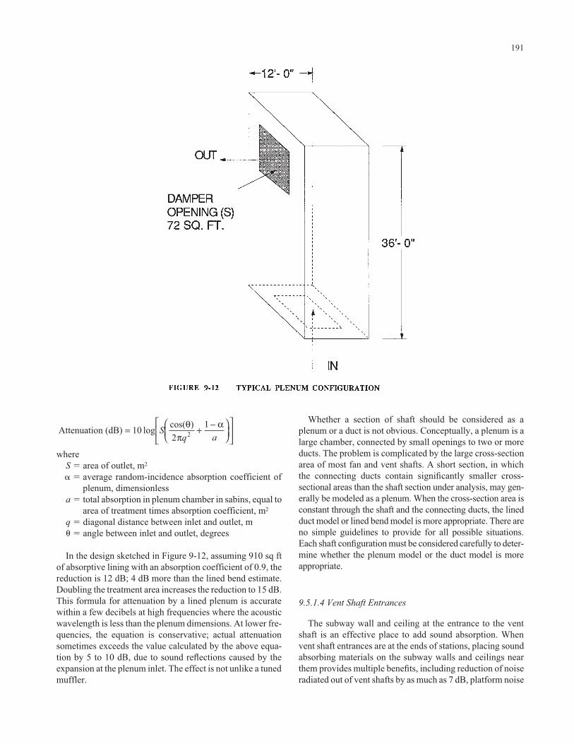
whereS � area of outlet, m2
� � average random-incidence absorption coefficient ofplenum, dimensionless
a � total absorption in plenum chamber in sabins, equal toarea of treatment times absorption coefficient, m2
q � diagonal distance between inlet and outlet, m� � angle between inlet and outlet, degrees
In the design sketched in Figure 9-12, assuming 910 sq ftof absorptive lining with an absorption coefficient of 0.9, thereduction is 12 dB; 4 dB more than the lined bend estimate.Doubling the treatment area increases the reduction to 15 dB.This formula for attenuation by a lined plenum is accuratewithin a few decibels at high frequencies where the acousticwavelength is less than the plenum dimensions. At lower fre-quencies, the equation is conservative; actual attenuationsometimes exceeds the value calculated by the above equa-tion by 5 to 10 dB, due to sound reflections caused by theexpansion at the plenum inlet. The effect is not unlike a tunedmuffler.
Attenuation (dB) 102
12= + −⎛
⎝⎜⎞⎠⎟
⎡
⎣⎢
⎤
⎦⎥log cos( )S
aθ
πα
q
191
Whether a section of shaft should be considered as aplenum or a duct is not obvious. Conceptually, a plenum is alarge chamber, connected by small openings to two or moreducts. The problem is complicated by the large cross-sectionarea of most fan and vent shafts. A short section, in which the connecting ducts contain significantly smaller cross-sectional areas than the shaft section under analysis, may gen-erally be modeled as a plenum. When the cross-section area isconstant through the shaft and the connecting ducts, the linedduct model or lined bend model is more appropriate. There areno simple guidelines to provide for all possible situations.Each shaft configuration must be considered carefully to deter-mine whether the plenum model or the duct model is moreappropriate.
9.5.1.4 Vent Shaft Entrances
The subway wall and ceiling at the entrance to the ventshaft is an effective place to add sound absorption. Whenvent shaft entrances are at the ends of stations, placing soundabsorbing materials on the subway walls and ceilings nearthem provides multiple benefits, including reduction of noiseradiated out of vent shafts by as much as 7 dB, platform noise

caused by trains approaching the station, and fan noise trans-mitted to the stations via the tunnels. Placing special soundabsorbing treatment at vent shaft entrances is most effectivewhen the subways do not normally have such treatment. Intreated subways, additional treatment in the transition sectionof the vent shaft is usually only mildly effective; the amountof improvement depends on specific design details.
The added attenuation achieved with a thick absorptiontreatment on the tunnel walls and ceilings is 5 to 7 dBA, com-pared to no lining at all. If a thin treatment is used, theexpected noise reduction is 3 to 5 dBA at 500 and 1,000 Hz.These figures assume that the walls and ceiling of the subwayare lined for 50 ft on each side of the vent shaft entrance.Train noise radiated from the vent shaft can be furtherreduced by lining the shaft with acoustical absorption, as isdiscussed in the preceding section.
9.5.1.5 Fan Attenuators
In-line duct silencers installed to reduce fan noise in com-munities will necessarily reduce wheel/rail noise transmittedthrough the fan shaft to the community. Attenuators placedto reduce station noise will have no effect on wheel/rail noisetransmitted to the station platform area, because the train willbe on the same side of the attenuator as the station platform.Many types of silencers are available for installation on ven-tilation fans. Prefabricated attenuators are available in bothrectangular and cylindrical shapes, and either a conical or around-to-rectangular transition section can be used to couplethe silencer to the fan.
In general, the selection of a fan attenuator depends on theamount of attenuation required, which will be determinedprimarily by the fan sound power, rather than wheel/railnoise. If all required noise reduction is to be provided by thesilencer, a unit is needed that provides sufficient attenuationin the 500 Hz and 1,000 Hz octaves. A number of factorsshould be considered when selecting an appropriate attenua-tor. The first is whether a rectangular or a cylindrical unit isneeded, a choice that will probably be decided on the basisof length and convenience of installation. In general, rectan-gular units are shorter, and often less expensive, than cylin-drical ones. Rectangular attenuators are typically supplied asmodules in lengths of 3 ft, 5 ft, 7 ft, or 10 ft. The cross-sectional area depends on the limitations on head loss andface velocity of the airflow through the unit. For subway ven-tilation fans, round units that give sufficiently low head lossvary from 10 to 16 ft in length. The round units are thereforeless desirable, in view of probable space limitations.
After the configuration to be used is selected, the maxi-mum permissible head loss determines the size and type ofunit. Rectangular units can provide sufficient noise reductionwith satisfactorily low head loss if the appropriate cross-sectional area is selected. For example, rectangular units,ranging from 25 sq ft to 100 sq ft in total cross-sectional areacan be obtained with appropriate attenuation ratings and head
192
loss in the range of 25 to 75 Pa (0.1 in. to 0.3 in. of water) at60,000 cfm airflow. Rectangular units are probably a betterchoice, since they are available in relatively short lengths andoffer good noise attenuation. A 3-ft length can provide atten-uation at 500 Hz in the range of 12 to 26 dB, depending onthe head loss rating. At 500 Hz, a 5-ft long unit can provideattenuation in the range of 17 to 37 dB, and a 7-ft long unitcan provide attenuation in the range of 23 to 46 dB. The headloss for 60 in. diameter round silencers which could bedirectly attached to the fans varies from 25 to 100 Pa (0.1 in.to 0.4 in. of water), at 60,000 cfm airflow. Attenuations pro-vided by these silencers vary from 10 to 34 dB. However, theminimum available length is 10 ft, and some units are as longas 15 ft.
The noise reduction rating for a selected attenuator underthe design air flow face velocity and volume must be used indesign. Although not a general practice, some attenuator cat-alogs still present sound attenuation data under static condi-tions. When air is flowing in the same direction as the soundpropagation, attenuation will be less than it is under staticconditions by a few decibels, depending on flow velocity orvolume.
9.5.1.6 Fan Rooms
When a fan room acts as an intake or discharge plenum,significant noise reduction is possible through lining the fanroom with acoustical treatment. However, when axial fansare installed within the ductwork, sound-absorbing materialin the fan rooms will not reduce the transmission of trainnoise to the street.
9.5.2 Fan and Vent Shaft Noise Prediction
Train noise radiated from fan and vent shafts can causeannoyance in the community. The noise reaching a receiverposition at the surface is dependent upon the sound poweremission of the train, which is speed dependent; the soundpower transmitted from the subway into the shaft; the atten-uation of sound energy as it travels up the shaft to the sur-face, and, finally, the distance and angle of the receiver rela-tive to the shaft opening. Figure 9-13 illustrates levels of ventshaft noise calculated at the WMATA Metro system.
The sound power transmitted from a subway tunnel into avent shaft can be approximated as
LW � Lp � 10 Log(As) – 6 dB
whereLp � sound level in the tunnel when the train is passing
the vent shaftAs � area of shaft opening, in m2
LW � sound power level transmitted into the shaft, dB re10–12 watts

The sound level reaching a receiver near the shaft openingand the required sound attenuation can then be estimated inthe same manner as for fan noise. The sound level at receiverlocations is given by
Lpq � LWR � DIq – 20 Log(r) – 8 dB
whereLpq � Sound pressure level measured at distance r and
angle q from the source, dB re 1 micro-Pascal.Diq � Directivity Index
193
r � Distance from the shaft centerLWR � Radiated sound power
The radiated sound power is simply the input sound powerlevel, LW, reduced by the shaft attenuation. In an untreated con-crete shaft, a maximum of 2 to 3 dB attenuation may exist, butmost of the available sound power is radiated to the community.
Measured directivity factors are presented in Figure 9-14.The directivity index increases as the angle above the hori-zon increases. From these results, the noise level at a receivercan be obtained.
FIGURE 9-13 WMATA DESIGN CURVES FOR MAXIMUM EXPECTED TRAIN NOISE AT 30 FEET FROM SHAFTGRATINGS
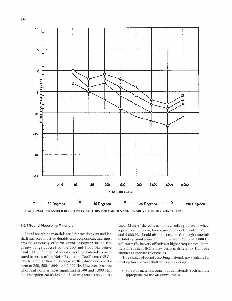
9.5.3 Sound Absorbing Materials
Sound absorbing materials used for treating vent and fanshaft surfaces must be durable and economical, and mustprovide extremely efficient sound absorption in the fre-quency range covered by the 500 and 1,000 Hz octavebands. The efficiency of sound absorbing materials is mea-sured in terms of the Noise Reduction Coefficient (NRC),which is the arithmetic average of the absorption coeffi-cient at 250, 500, 1,000, and 2,000 Hz. However, becausewheel/rail noise is most significant at 500 and 1,000 Hz.,the absorption coefficients at these frequencies should be
194
used. Most of the concern is over rolling noise. If wheelsqueal is of concern, then absorption coefficients at 2,000and 4,000 Hz should also be considered, though materialsexhibiting good absorption properties at 500 and 1,000 Hzwill normally be very effective at higher frequencies. Mate-rials of similar NRC’s may perform differently from oneanother at specific frequencies.
Three kinds of sound absorbing materials are available fortreating fan and vent shaft walls and ceilings:
• Spray-on materials cementitious materials, such as thoseappropriate for use on subway walls.
FIGURE 9-14 MEASURED DIRECTIVITY FACTORS FOR VARIOUS ANGLES ABOVE THE HORIZONTAL LINE

• Conventional glass-fiber boards or blankets, mechani-cally attached to the fan and vent shaft interior surfaces.
• Cellular glass blocks, mechanically attached or adheredto walls.
9.5.3.1 Spray-On Materials
Spray-on materials are the easiest to install, and may becheaper than glass-fiber materials. The number of satisfac-tory spray-on products is much more limited than glass-fiberblanket or board materials. Many spray-on materials eitherprovide very little sound absorption, or are not durableenough for use in subway fan and vent shaft installations.Those considered effective based on reported transit agencyexperience include, but are not limited to
Cafco “Sound Shield 85,” supplied by the United StatesMineral Products Company, Stanhope, New Jersey.
“Kilnoise Acoustic Plaster,” supplied by Pfizer Minerals,Pigments & Metals Division, New York.
“Pyrok,” supplied by Pyrok Company, New York.“Pyro-Spray,” supplied by Baldwin-Ehret-Hill, Inc., Tren-
ton, New Jersey.
All of these materials have similar absorption characteris-tics when applied in thicknesses of 5/8 to 3/4 in. When prop-erly installed, all are durable enough to withstand repeatedcleaning or washing with water spray. The installation pro-cedures must be clearly defined and monitored to ensure adurable application. Improper installation may result in inad-equate acoustical performance and poor adhesion to surfaces.
Spray-on material applied to fan and vent shaft surfaces inthicknesses of 3/8 in. to 3/4 in. will provide absorption coeffi-cients of 0.45 to 0.55 at 500 Hz and 0.70 to 0.80 at 1,000 Hz.Reported absorption coefficients for 1-in. thick treatmentapplied directly to a concrete surface include 0.24 and 0.42at 500 and 1,000 Hz, respectively. Evaluation of the initialinstallations at WMATA subways confirmed that these fig-ures are reasonably accurate. The measured values for 1-in.thick treatment were 0.17 and 0.39 at 500 and 1,000 Hz,respectively (22). Although these figures are less than thosereported by the manufacturer for laboratory test results, theyare still sufficient to provide significant noise reduction.
9.5.3.2 Glass-Fiber Boards and Blankets
Glass-fiber boards or blankets provide the highest soundabsorption coefficient, and, therefore, the highest soundabsorption for the amount of area covered. A wide range ofglass-fiber blanket and board materials will satisfactorilycontrol fan and vent shaft noise. The materials should have adensity of 1.5 to 6 pcf, with or without sprayed on vinyl orneoprene protective coating. The most economical and
195
appropriate material is glass-fiber duct liner, as used in ven-tilation system ducts. This material is generally available in1-in. thickness; two layers can be used to obtain a 2-in. thick-ness. Materials for sound absorption treatment includeOwens-Corning Fiberglass rigid or semirigid board. Johns-Manville and Certain-Teed/St. Gobain (Gustin-Bacon) sup-ply similar material, with equivalent mechanical and acousti-cal characteristics.
Where mechanical protection of the material is necessary,the installation may include an outer covering of acousticallytransparent hardware cloth or expanded metal. Dust or dirtcollecting on the surface of the glass fiber will not signifi-cantly affect its sound absorption characteristics, althoughdust can be a fire or smoke hazard. Water has no permanentdegrading effect on the sound absorbing ability of glass fiber,but absorption is reduced while the material is wet. Over thecourse of time, the detergents used in tunnel washing mayleave an accumulation of residue, the effects of which are notyet known.
Glass-fiber material can be kept from collecting dirt andabsorbing water by enclosing it in an envelope of Tedlar ofthickness no greater than 0.003 in. Any plastic film with athickness of 0.004 in. or less is acoustically satisfactory if itsweight is less than about 0.3 oz/sq ft. The selection of plas-tic film must be based on the life expectancy of the tunnel andthe fire resistance of the material. In many outdoor environ-ments, mylar or polyethylene film is used. However, whenthe fire resistance capacity of these materials is unacceptable,a polyamide film such as DuPont Kapton or any other fire-resistant material should be considered.
A number of procedures can be used to attach glass-fiberboards and blankets to concrete surfaces. In machineryrooms and concrete ducts, “Stic Klips” (similar to largeheaded nails) can be used, either cast in the concrete or fastened to the concrete with cement or epoxy. The glass-fiber material is impaled on the rod, a washer is placed over the rod, and the rod is bent over the washer to retainthe material and any added protective covering. Wood or metal furring strips, attached to the concrete surface, canbe used with mechanical fastening to support and re-tain the glass fiber. An “acoustical stud” or similar shapedmetal extrusion can be used to attach 2 in. thick material toconcrete walls, without using fasteners that penetrate the glass fiber or protective coating. Such mountings areespecially convenient when a waterproof covering is to be used.
Fire safety is a major concern when specifying acousticaltreatments for subway applications. A glass fiber with nobinder is necessary to achieve an incombustible product.However, very few products are manufactured withoutbinders because glass fiber tends to lose fibers when there isno binder material. Temp-Mat, from Pittsburgh Corning, isone example of a glass-fiber product held together by amechanical felting process that contains no binder. It doescontain a small amount of residual oil, used in the manufac-

turing process, which can be baked out by the manufacturer.It has a density of 11.25 pcf in the 1-in. thickness, which istwo or three times the density normally recommended forglass-fiber acoustical absorption. The density of Temp-Matmakes it cost more than lower density materials, but itsacoustical performance will be as satisfactory as lower den-sity 6 pcf glass fiber of the same thickness.
9.5.3.3 Cellular Glass Blocks
Geocoustic Blocks, a proprietary product of PittsburghCorning, have been used successfully in a number of subwayapplications. They are made of rigid porous glass foam inthicknesses of 2 and 4 in., and are slotted to increase theeffective surface area and absorption. The manufacturerstates, and tests confirm, that these blocks have absorptioncoefficients above 0.90 at 500 and l,000 Hz. GeocousticBlocks have the significant advantage of being completelyinorganic and incombustible. However, they have the disad-vantage of shedding small glass granules. The manufacturerhas experimented with a spray-on coating to control the shed-ding problem, but this adds an organic component to thematerial that might increase fire-related problems. The Geo-coustic Blocks are no longer regularly supplied, though theymight be obtained provided sufficient quantities are ordered.
9.6 RECEIVER TREATMENTS
Receiver treatments include improving the sound insula-tion characteristics of homes or other sensitive structures,usually by retrofitting glazing and doors with acousticallyrated units. Receiver treatment has become popular for air-craft noise control, where interior Day Night Levels (Ldn)may exceed 45 dBA. Receiver treatment should be consid-ered as the last approach for controlling wheel rail noise,since there are no established criteria for interior noise fromrail transit systems, and the interior noise limit of Ldn 45 rec-ommended by the Environmental Protection Agency forcommunity noise exposure is not likely to be exceeded bywheel rail noise, provided that the system is in good condi-tion and that receivers are not located within a few feet of thesystem. A second reason for avoiding receiver treatment isthat during the process of retrofitting windows and doors,pest damage and/or code violations may be encountered, thecorrection of which may require substantially greater fundsthan needed just for the retrofit. In effect, the transit systemmay become responsible for the overall improvement of thestructure. Nevertheless, the experience obtained with aircraftnoise insulation projects may serve as a valuable guide. Forthose pathological situations where a receiver is locatedwithin a feet of the transit system, or where rail corrugationcannot be controlled adequately, and a sound barrier isimpractical, treatment of windows and doors remains as aviable option, unless they are already acoustically effective.
196
The best approach is to replace, where appropriate, anexisting window with a complete unit consisting of glass,mullion, weather stripping, and miscellaneous hardware. Innewer homes built to thermal insulation code requirementsin colder climates, the windows may already be sufficientlyeffective in controlling interior noise. Often, storm windowsand doors are added to existing windows and doors, respec-tively, to improve the sound insulation properties of thesecomponents. The selection of windows or doors should bebased on the spectrum and level of wheel/rail noise. Typi-cally, a door or window with a Sound Transmission Class(STC) of 30 should be adequate. Higher STC ratings may beneeded if sound levels are particularly high, or involve puretones due to rail corrugation, or impact noise from specialtrackwork.
Treatment of residential receivers may require permanentclosure of operable windows. This may, in turn, require pro-vision of mechanical ventilation or air conditioning systems,an expense which may greatly increase the cost of mitigation.Further, if not properly selected, mechanical ventilation andair conditioning systems may produce their own noiseimpacts.
Contrary to popular opinion, typical or common thermalinsulating glass consisting of two identical glass layers sep-arated by a 1/4- or 1/2-in. air space provides poor sound in-sulation compared to acoustically rated glass. A betterapproach is to use single layer laminated glass, thermallyinsulating glass with dissimilar glass thicknesses, or ideally,thermally insulating glass with at least one laminated glasspane. In spite of the poor performance of common thermallyinsulating glass, the requirements of the mullions and fram-ing for limiting air intrusion are acoustically beneficial, andsuch installations will generally be superior to simple case-ment or sash windows regardless of glass characteristics.Again, sealing air leaks in windows or doors is alwaysacoustically beneficial.
9.7 REFERENCES
1. Kurze, U. J, and G. S. Anderson, “Sound Attenuation by Bar-rier,” Applied Acoustics, Vol. 4, No. 1 (January 1971).
2. Maekawa, J., Noise Reduction by Screens, Mem. Fac. Eng.,Kobe University, 11 (1965).
3. Kurze, U. J., and G. S. Anderson, “Sound Attenuation by Bar-riers,” Applied Acoustics, Vol. 4, No. 1 (January 1971).
4. Peters, S., “The Prediction of Railway Noise Profiles,” Journalof Sound and Vibration, Vol 32, No.1 (January 8, 1974) pp.87–99.
5. Peters, S.,“Prediction of Rail-Wheel Noise from High SpeedTrains,” Acoustica, Vol. 28, No. 6 (June 1973), pp. 318–321.
6. Saurenman, H. J., J. T. Nelson, G. P. Wilson, Handbook ofUrban Rail Noise and Vibration Control, UMTA–MA–06–0099–82–1 (February 1982).
7. Hanson, C., et al. Draft Guidance Manual for Transit Noiseand Vibration Impact Assessment, Harris, Miller, Miller, &Hanson, for U.S. DOT/FTA 1990 (Unpublished).

8. Transit Noise and Vibration Impact Assessment, Federal Tran-sit Administration, U.S.DOT, Chapter 3 (April 1995).
9. Towers, D. A., Noise Barrier Study for the Metropolitan DadeCounty Rapid Transit System—Phase I, Bolt Beranek andNewman Inc. Report No. 5677 (1984).
10. Personal communication from W. F. King III (1995). 11. Fischer, H. M., “Noise Generation by Railroad Coaches,”
Journal of Sound and Vibration, Vol. 66, No. 3 (1979), pp.333–349.
12. Parent De Curzon, E. and B. Bequet, “Study into Sources ofWagon Noise: Measurement of Sound Energy Generated byVehicle Bodies and Running Gear,” Journal of Sound andVibration, Vol. 120, No. 2 (1988), pp. 311–320.
13. Wilson, G. P., At-Grade and Aerial Stations in HighwayMedians, Wilson, Ihrig & Associates, Inc., prepared for theWashington Metropolitan Area Transit Authority, February1973.
14. Wilson, G. P., “Rail Transit System Noise Control,” Noise–Con77 Proceedings, 1977 National Conference on Noise ControlEngineering (October 1977).
15. Wilson, G. P., “Rail Transit System Noise Control,” Noise–Con77 Proceedings, 1977 National Conference on Noise ControlEngineering (October 1977).
197
16. Wilson, G. P., “Rail Transit System Noise Control,” Noise–Con77 Proceedings, 1977 National Conference on Noise ControlEngineering (October 1977).
17. Wilson, G. P., Sound Absorption System for Metro Tunnels andStation Platforms, Wilson, Ihrig & Associates, Inc., prepared forWashington Metropolitan Area Transit Authority (June 1971).
18. George Paul Wilson, “Rail Transit System Noise Control,”Noise–Con 77 Proceedings, 1977 National Conference onNoise Control Engineering (October 1977).
19. H. J. Saurenman, J. T. Nelson, G. P. Wilson, Handbook ofUrban Rail Noise and Vibration Control, Wilson, Ihrig &Associates, Inc. For U.S. DOT/UMTA (February 1982) (NTISNo. UMTA–MA–06–0099–82–1) Chapter 9.
20. H. J. Saurenman, J. T. Nelson, G. P. Wilson, Handbook ofUrban Rail Noise and Vibration Control, Wilson, Ihrig &Associates, Inc. For U.S. DOT/UMTA, Final Report (February1982). (NTIS No. UMTA–MA–06–099–82–2) Chapter 10.
21. ASHRAE Guide, American Association of Heating, Refrigera-tion, and Ventilation Engineers.
22. Nelson, J. T., and G. P. Wilson, Metrorail Operational SoundLevel Measurements: Substation Noise Levels, Preliminaryreport prepared by Wilson, Ihrig & Associates, Inc. for theWashington Metropolitan Area Transit Authority (June 1979).

CHAPTER 10: RAIL CORRUGATION CONTROL
10.1 Introduction, 19910.2 Classification of Corrugation, 199
10.2.1 Roaring Rail, or Short Wavelength Corrugation, 19910.2.1.1 Relation to Rail Support Stiffness, 20010.2.1.2 Wheel/Rail Dynamic Forces, 20110.2.1.3 Stick-Slip Wear Mechanism, 20110.2.1.4 Rail Steels, 20310.2.1.5 Rail Support Spacing, 203
10.2.2 Rutting Corrugation, 20310.2.3 Booted Sleeper, 20410.2.4 Resilient Wheels and Rail Corrugation, 204
10.3 Treatment of Rail Corrugation, 20410.3.1 Rail Grinding, 204
10.3.1.1 Preventive Grinding, 20510.3.1.2 Profile Grinding, 20510.3.1.3 Rail Grinding Frequency, 20510.3.1.4 Grinding Depth, 20510.3.1.5 Profile, 20610.3.1.6 Variation of Contact Patch Location, 206
10.3.2 Lubrication, 20610.3.2.1 Onboard Solid-Stick Flange Lubrication, 20610.3.2.2 Onboard Solid-Stick Friction Modifiers, 207
10.3.3 Hardfacing, 20710.3.4 Rail Selection, 20710.3.5 Rail Support Modulus, 20710.3.6 Trackwork Resonances, 208
10.3.6.1 Rail Support Spacing, 20810.3.6.2 Direct Fixation Fastener Mechanical Impedance, 209
10.3.7 Speed Variation, 21010.3.8 Super-Elevation, 210
10.4 References, 210
198

199
CHAPTER 10
RAIL CORRUGATION CONTROL
10.1 INTRODUCTION
Rail corrugation causes some of the most seriouswheel/rail noise problems experienced by transit systems.The noise is irritating, and can be painful and possibly harm-ful to patrons in subways. At the wayside, wheel/rail noisedue to corrugated rail contains a distinctive tonal character,and the noise may be heard and identified at many miles fromthe track, especially under certain wind and temperature con-ditions. While noise from corrugated rail is particularlysevere and may be a source of significant community reac-tion, it is also relatively easily controlled by rail grinding.The only, and not insignificant, limitations are availablefunding for rail grinding equipment and materials and per-sonnel, and track time for grinding.
Presented below are discussions of the corrugation andpossible treatment methods, based on the literature, anecdo-tal information, and the experience of the authors. Substan-tial research has been conducted within the last 10 to 15 yearswhich appears to be culminating in a relatively clear pictureof various corrugation processes. Particularly relevant is arecent survey of corrugation formation at rail transit systems(1), which provides a comprehensive discussion of rail cor-rugation formation and track configurations which may con-tribute to corrugation. A rather thorough review of the liter-ature and state-of-the-art in methods of control has beenprovided by Grassie and Kalousek (2), who indicate that con-cern over rail corrugation has existed since the beginning ofrailroading. In 1961, British Rail had compiled a list of ref-erences from the year 1904, and the level of interest andresearch in the area has not abated.
10.2 CLASSIFICATION OF CORRUGATION
Rail corrugation is defined as a periodic longitudinal railhead profile brought about by either wear or plastic flow ofthe rail head running surface. Rail corrugation consists ofthree basic wavelength regimes:
1. “Roaring Rail” corrugations with wavelengths of 1 to 3 in. These are usually associated with light axle load operations such as at transit systems and com-muter/passenger operations. The term “short pitch” issynonymous with roaring rail. At BART, roaring rail is also described as “howling rail.”
2. Intermediate Wave Corrugations with wavelengths of6 to 18 in. These are usually associated with heavy-axle-load freight operations and are most frequently foundon the low rail of curves.
3. Long-Wave Corrugations with wavelengths greaterthan 24 in. These are usually associated with highspeed passenger operations, but can be found on otherlow speed track as well.
The above classifications pertain to the phenomenologicalcharacteristic which is most readily observed, namely, cor-rugation wavelength.
Rail corrugation has been classified by Grassie andKalousek (3) into six categories, including (1) heavy haul, (2)light rail, (3) booted sleeper, (4) contact fatigue, (5) rutting,and (6) roaring rail. The various classifications are listed inTable 10-1.
10.2.1 Roaring Rail, or Short WavelengthCorrugation
Roaring rail or short-pitch corrugation often producessevere noise at moderate to high vehicle speeds, and is oftenresponsible for community noise complaints. Not only is thenoise from short-pitch corrugation higher than from rail insmooth condition, but it has a tonal character centered atabout 500 to 800 Hz, and is much more easily detected anddifficult to ignore than normal rolling noise.
One of the most comprehensive discussions of short wave-length corrugation is provided by C. O. Frederick, ChiefCivil Engineer of British Railways Board (4). Several obser-vations are made by Frederick, drawing on the literature andhis own work for high speed rail operations in Britain:
1. Corrugation exhibits severe plastic deformation at thecrests, and only mild plastic deformation in the troughs.
2. Corrugation is essentially stationary in position. Thepeaks and troughs do not translate as the wear pro-gresses. The entire rail loses material, and the rate ofloss appears to be greater at the trough than at the crest,which process produces the corrugation. For very smallwave amplitudes, the rate of corrugation deepening isproportional to the existing depth (leading to anexponential rate of growth with time).

3. Corrugation waves at the two rails do not appear to becorrelated with distance down the track, and do notform an absolutely periodic pattern. (Correlation ofcorrugation between rails has been observed else-where.)
4. Corrugation appears first at the running edge of con-crete ties, and not at all on paved track with continuousrail support, indicating that the corrugation is somehowrelated to the geometry of the rail support (the supportstiffness is also different for paved continuous supportversus concrete ballast and tie track).
5. Open hearth steel is less prone to corrugate than AcidBessemer steels. Steels with low resistance to plasticyield form corrugations very slowly, and steels withhigh resistance to plastic yield form corrugations veryrapidly, though an increase in wear resistance helps toslow the rate of corrugation formation.
6. Grinding rails smooth immediately after installation inthe track substantially delays corrugation formation.Corrugation reforms quickly after grinding rail that hasalready been corrugated, and this may be due to resid-ual corrugation. (Residual periodic work hardeningwould be another factor.)
Moreover, corrugation wavelengths are observed to belargely independent of train speed, indicating that a wave-length fixing mechanism rather than a mechanical resonancefrequency fixing mechanism is at work. A geometric fixingmechanism for wavelengths supports the theory of railcorrugation caused by stick-slip or roll-slip. Wear appears as
200
the principal corrugation mechanism, rather than plasticdeformation.
Frederick’s observations of short-pitch corrugation phe-nomena and sensitivity to treatment appear to be supportedby others. Following below are discussions of the variousparameters that may affect short-pitch corrugation.
10.2.1.1 Relation to Rail Support Stiffness
Short-pitch corrugation is often present at track with rela-tively stiff rail supports and where rail grinding is not per-formed regularly. Examples include corrugation at the TTCScarborough Line with Pandrol plates and Landis elastomerpads. A recent survey of transit system corrugation lists elas-tomeric direct fixation track as one of several types of trackwhich exhibit a corrugation rate of 40 to 50% of track (5).Although not identified, support stiffness may be the princi-pal parameter responsible for corrugation at direct fixationtrack.
Older designs of resilient direct fixation fasteners at U.S.transit systems tend to have relatively high stiffness. New transit system track, such as the new BART exten-sions, WMATA Metro, and Los Angeles Metro, areemploying fasteners of generally lower stiffness. In fact,the tendency in direct fixation track design has been towardusing progressively softer direct fixation fasteners witheach new transit construction. The influence of soft tracksupport stiffnesses has not yet been reflected in surveys ofcorrugation conducted to date. Daniels indicates a need to

evaluate the influence of track stiffness on rail corrugationformation (6 ).
Daniels indicates that the rail support modulus did nothave a conclusive effect on ballast-and-tie curved track atFAST during heavy railroad tests (7 ). Where substantial railcorrugation occurs on direct fixation track, relatively stifftrack fasteners are involved, though insufficient data areavailable to draw definite conclusions. Stiff track support isconjectured by some authors to exacerbate the “pinned-pinned” resonance related to the discrete track supports, andreduction of support stiffness might be beneficial in reducingthis possible interaction (8).
Reduction of tie-saver pad stiffness to remove coinci-dence between the rail/tie vertical anti-resonance andwheelset 2nd order bending and torsional vibration modesappears to have been effective at the RATP in reducing or eliminating booted sleeper rail corrugation at 380-mradius curves. This is perhaps the most dramatic demon-stration of the rail corrugation control effectiveness byreducing rail support stiffness. A study of two-block tie corrugation at the Baltimore Metro system suggests thatreduction of the tie-saver pad stiffness by 50% would besufficient to control corrugation at curved track (9). How-ever, work by Grassie et al. indicates that reduction of tie pad stiffness at British Rail may not be beneficial, as discussed above (10).
Concrete tie track exhibits corrugation in the range of 6 to 12 in., compared to wood tie and ballast track, where thepredominant corrugation wavelength is 12 to 24 in. Com-puter modeling indicates that contact patch forces on con-crete tie track can be reduced dramatically in the range of 200Hz if relatively soft (1,000,000 lb/in.) pads are used in lieu ofstiff (8,000,000 lb/in.) pads (11).
201
10.2.1.2 Wheel/Rail Dynamic Forces
Corrugations (as well as the other rail surface defects) willgenerate dynamic wheel/rail interaction forces that aredirectly dependent on the magnitude of the defect and thespeed of the vehicle. The periodic nature of rail corrugationproduces an increasing dynamic wheel/rail force of thenature shown in Figure 10-1. As can be seen in this figure,these forces build up to maximum value very quickly, typi-cally within 50 milliseconds (which corresponds to less than3 ft for a vehicle travelling at 40 mph).
Analysis of these dynamic forces in the vertical planeresults in the relationship presented in Figure 10-2 which pre-sents wheel/rail contact force as a function of corrugationdepth and frequency (which in turn is a function of vehiclespeed and corrugation wavelength). The transit system’scombination of speed and wavelengths (1 to 3 in.) generatecorrugation frequencies of 150 Hz and greater (see Figure10-3). While this does not appear to generate significantdynamic activity for corrugation depths of 0.005 in., deepercorrugations do generate increased dynamic load levels atthese high frequencies.
10.2.1.3 Stick-Slip Wear Mechanism
Grassie and Kalousek indicate that roaring rail corrugationis occasioned by high contact forces at the peaks of the cor-rugation and low contact forces resulting in slip at thetroughs. Stick-slip wear as a corrugating mechanism is alsosupported by Grassie et al. in a mathematical and experi-mental study of short-pitch corrugation (12). Creep is pre-dicted at corrugation valleys due to an out-of-phase relation-ship between wheel/rail contact force and rail profile over a

broad frequency range above roughly 500 Hz, not necessar-ily involving a resonance condition. The contact force is at aminimum at corrugation troughs, allowing longitudinal (andlateral) slip to occur, and thus wear. The results are consis-tent with wear patterns observed at short-pitch corrugatedtracks. These authors further indicate that rail pad resonance
202
does not appear to contribute to short-pitch corrugation, andthat reduction of rail pad stiffness will not significantlyreduce corrugation rates. This conclusion differs from that of Daniels, who has suggested reducing pad stiffness atBaltimore MTA to reduce corrugation in connection with thetwo-block booted ties (13).

“Roll-slip” behavior (14) has been identified by Kalousekand Johnson at the Vancouver Skytrain (15), and they havefurther identified a possible relationship between spin-creep and rail corrugation, brought on by wide contact band, hightread conicity, and high wheel/rail conformity due to treadwear. High wheel/rail conformity evidently leads to high-frequency local oscillations at about 800 Hz involving rota-tion and translation of the rail, producing short-wavelengthcorrugations. These are “aggravated” by a small amount oflateral slip (16 ). However, at BART, substantial short-pitchcorrugation occurs on tangent track with cylindrical wheels,suggesting that wheel tread conicity is not necessary forgeneration of corrugation.
In any rolling motion, creep must occur due to the finitesize of the contact patch. The creep may be occasioned byroll-slip behavior, due to decreasing friction with increasingcreep. Roll-slip behavior may be determined primarily bygeometrical characteristics such as contact patch dimensions,because short-pitch corrugation often has a wavelength that is relatively independent of vehicle speed, as noted byFrederick. If the corrugation wavelength was directly pro-portional to train speed, then mechanical resonances wouldbe expected to be the sole cause of the corrugation. Ofcourse, constant wavelength as a function of speed is notnecessarily the rule, either.
Kalousek indicates that not all wheels nor all sections oftrack are subject to stick-slip oscillation and corrugation.Further, “saturated” creepage is required to generate stick-slip oscillations, and only each twentieth to fiftieth wheelsetwould be sufficiently misaligned or have other geometricalinconsistency leading to corrugation. Further, Kalousek indi-cates that asymmetrically worn wheelsets, or misalignedwheelsets due to inadequate maintenance of the track or vehi-cle, are prone to excite stick-slip oscillations: “Wheelsetswith new wheels or turned wheels, installed in well alignedtrucks and negotiating tangent track cannot and will not pro-duce stick-slip oscillation” (17 ).
10.2.1.4 Rail Steels
Grassie and Kalousek indicate that short wavelength cor-rugation appears to be more extensive with acid Bessemerthan with open hearth rail steels, and appears to be moderatewith oxygen rail steels. (This may be a reiteration of Freder-ick’s comments.) Interestingly, rail hardness does not appearto affect short-pitch corrugation rates, at least at tangenttrack. However, Daniels reports that corrugation rates atcurved track with hardened or alloy steel rail are roughly halfthose of carbon steel rail (18).
10.2.1.5 Rail Support Spacing
The corrugation amplitude appears to be modulated at a spa-tial wavelength corresponding to tie spacing, with the moresevere corrugation on the approach to the ties than between in
203
the case of resiliently supported ties (19). This effect may berelated to so-called “pinned-pinned” resonances of the rail atfrequencies of about 350 and 800 Hz. The discrete track sup-ports tend to inhibit motion of the rail, thus creating thepinned-pinned resonance. The associated wavelength of railvibration is twice the support spacing, considering the rail tobe simply supported at the fasteners, hence the term “pinned-pinned.” Theoretical studies support this mode of vibration inmodulating the amplitude of corrugation (20).
The pinned-pinned resonance frequency for verticalmotion of the rail is between 500 and 750 Hz for fastenerspacings on the order of 30 to 36 in., based on a model ofbeam bending and accounting for rotary inertia and trans-verse shear. This is precisely the range of corrugation fre-quencies observed at many transit systems. By reducing thefastener spacing to 24 in., the pinned-pinned mode frequencywould be increased to the order of 1,000 Hz, sufficiently highto produce a wavelength of about twice the contact patchlength, or about 11⁄4 in. for 70 mph trains. Corrugation wavesless than twice the contact patch length might reasonably beexpected to be smoothed by the contact patch, though this hasnot been demonstrated. However, corrugation wavelengthsof less than 1 in. or 11⁄4 in. do not appear to exist. Note thatthis type of corrugation generation is at odds with the notionof geometrical causes producing stick-slip, so that consider-able study is required before excessive support spacing canbe blamed for rail corrugation.
Models predict reduced corrugation rates for wear-induced corrugation at tangent track, e.g., “roaring rail,” withreduced rail support modulus and tie spacing. Again, the fix-ative agents appear to be the rail/tie and the “pinned-pinned”anti-resonance frequencies. Reduction of tie pad stiffnessfrom 770 MN/m to 280 MN/m lowered a 400 Hz anti-reso-nance of the tie and rail and effectively removed predictedrail corrugation with a wavelength of 9 cm. However, thepinned-pinned mode remains, producing a predicted corru-gation at about 3 cm wavelength. Reducing the tie spacingfrom 600 mm to 400 mm and reducing the pad stiffness tocompensate for closer tie spacing raises the pinned-pinnedmode anti-resonance from about 1,200 Hz to 2,000 Hz, atwhich frequency the predicted corrugation wavelength isreduced to 1.7 cm, sufficient, possibly, to be suppressed bythe contact patch size (or filter.) No corroborating field dataare available (21).
10.2.2 Rutting Corrugation
Rutting corrugation, the 5th form of corrugation identifiedby Grassie, is produced by windup and torsional resonanceof the axle. Grassie and Kalousek indicate that rutting corru-gation may occur at curves, braking sites and termini, andwhere both wheel sets are constrained by coupling to thesame truck motor, as with mono-motor trucks. Cures for rut-ting corrugation include lubrication of the high rail gaugecorner, use of hard rails, possibly use of a friction modifier,and avoidance of mono-motor trucks (22).

A particularly interesting study of torsional resonanceinduced corrugation indicates that two corrugation wave-lengths may be generated, one exactly twice the other (23).This phenomenon was observed in the FAST test data col-lected at the Pueblo, Colorado, Transportation Test Center(24). The mechanism evidently involves cyclic slip in boththe forward and reverse longitudinal directions, and appliesmainly to curves.
10.2.3 Booted Sleeper
This type of corrugation is related to a resonance conditionbetween the rail and resiliently supported concrete ties, con-trolled by the high stiffness of the resilient “tie-saver” pad. Acoincidence between the rail/tie resonance, axle bendingmode, and wheel torsional resonance is a possible cause,leading to corrugation frequencies on the order of 250 to 400Hz, well within the range of significance to wheel/rail noise(25). A similar relationship between rail and concrete tie wasinvestigated at the Baltimore MTA system (26). This type ofcorrugation is evidently unique to this two-block tie system.Reduction of pad stiffness (by a substantial amount) evi-dently eliminates this form of corrugation at the RATP (27),and a similar modification was proposed for the BaltimoreMTA by Daniels.
Booted sleeper corrugation, if significant, is particularlyimportant, given the popularity of the two-block tie systemas a vibration isolation provision. Installations includeMARTA, Baltimore MTA, Tri-Met, the Channel Tunnel,Paris Metro, and elsewhere. Although the two-block tie sys-tem provides vibration isolation, corrugation would negateany isolation benefit. The two-block tie concept is not neces-sarily conducive to corrugation, but certain parameters, suchas rail pad stiffness, may be responsible.
10.2.4 Resilient Wheels and Rail Corrugation
A seventh category of rail corrugation may exist. Corru-gation of tangent track has been experienced at many lightrail systems using resilient wheels. Examples include thePortland Tri-Met, PA Transit in Pittsburgh, Sacramento RTDMetro, the Los Angeles Blue Line ballast-and-tie and directfixation aerial structure track, Santa Clara Transit Agency,and others. The Greater Cleveland RTA has reported ripplecorrugation at station stops for light rail vehicles withresilient wheels, but no corresponding corrugation withheavy rail vehicles with solid wheels (survey questionnairereturn). The nature of the corrugation is similar to that oftangent track short-pitch corrugation, and may in fact haveidentical causes unrelated to wheel resilience.
A periodic pattern has been observed at the rail head at Tri-Met within a few weeks after rail grinding, the pattern beingrevealed by a variation in moisture at the top-of-rail after pas-sage of a transit train on a damp day (28). The cause of thepattern is not known. The Tri-Met vehicles use Bochum 54resilient wheels. The periodic pattern is indicative of periodic
204
motion of the wheel tread, which might result in corrugationover a sufficient period of time.
Corrugation at light rail systems using resilient wheelsshows up on both embedded and ballast-and-tie track. Anec-dotal evidence suggests that particularly sensitive types ofembedded track include urethane embedded track (PortlandTri-Met, Calgary), suggesting that a very high rail supportmodulus may be a contributing factor, possibly in combina-tion with soft steel girder rail. Some corrugation is alsoobserved at the concrete embedded track in Santa Clara,though reports are mixed. No corrugation appears at theresilient embedded track employed at the Los Angeles BlueLine. Infrequent rail grinding at many light rail systems maybe a principal factor in corrugation growth rates at these sys-tems. Further investigation of this phenomenon is necessaryto determine the actual influence, if any, of resilient wheelson rail corrugation.
10.3 TREATMENT OF RAIL CORRUGATION
A number of treatments have been proposed for control-ling rail corrugation, depending on the type of corrugatingmechanism involved.
Short wavelength corrugation was controlled at theVancouver Skytrain by the following measures (29):
1. Reduction of truck axle misalignment2. Profile grinding to reduce contact patch width and
move the wear strip laterally over different sections oftrack to avoid rutting of the wheel tread. Reduction ofcontact patch width is believed to reduce spin-slipmotion of the tire. Variation of contact position at therail head is employed to spread the wear of the tire, fur-ther inhibiting formation of tire surface concavitywhich would increase wheel/rail conformity and thusincrease spin-slip.
3. Use of a friction modifier to make the dynamic frictioncoefficient greater than the static friction coefficient.
The Vancouver system uses a steerable truck and smalldiameter wheels. However, these procedures should beapplicable to conventional heavy and light rail systems. Oneof the main points of the Vancouver experience is that a com-bination of treatments or procedures may be necessary tocontrol rail corrugation.
10.3.1 Rail Grinding
Rail grinding is the most effective control procedure forrail corrugation and wheel/rail noise in general. Other meth-ods are unpredictable at best, with no guarantee that theirimplementation will reduce or prevent corrugation. Mostmodern rail transit systems are actively engaged in rail grind-ing programs. The RATP regularly grinds corrugated sec-tions of track to control ground vibration (30), which shouldresult in lower levels of wayside and vehicle interior noise.

The Toronto Transit Commission and Chicago CTA regu-larly grind rail with block grinders to control wheel rail noiseand rail corrugation. Examples include the TTC ScarboroughSRT, main subway, and light rail systems (survey question-naire response). Chicago CTA regularly grinds track duringrevenue hours. BART is engaged in regular rail grinding witha rotary vertical axis grinding machine manufactured by Pandrol-Jackson. WMATA grinds tangent and curved trackwith a LORAM 24-stone grinder annually or whenever cor-rugations reach a depth of 0.010 in. Recently, the Los Ange-les County Metropolitan Transit Authority has purchasedand begun using a Fairmont Tamper vertical axis profilegrinder with great success in reducing wayside noise. Railgrinders are increasingly recognized as being essential in anynoise control program.
10.3.1.1 Preventive Grinding
Initial rail grinding prior to startup is of great importanceto maintain low dynamic contact forces and increase the timebefore corrugation appears. Rail corrugation was delayed bya period of five years by preventive rail grinding during astudy by British Rail (31). The SNCF uses preventive grind-ing to remove the decarbonized surface layer of the rail headby grinding new rail immediately after laying, taking off 0.30mm of rail head metal (32). The procedure reduces headchecking and fatigue cracking, improves rolling conditionsand weld performance, reduces energy consumption, andimproves ride comfort.
10.3.1.2 Profile Grinding
Profile grinding to optimize contact patch dimensions,while providing good ride quality characteristics, is desirableto define the contact strip edge and reduce roughness due tovariation in rail head ball radius.
10.3.1.3 Rail Grinding Frequency
Finish grinding on a periodic basis controls the formationof corrugation. As pointed out by Frederick, corrugationgrowth rates are largely exponential in nature. Waiting toolong before rail grinding, perhaps until corrugations are “vis-ible,” may allow large corrugations to occur prior to the timegrinding can be performed. Thus, grinding is desirable whencorrugation development is still on the low end of the “expo-nential curve.” Grinding off corrugations early maintains an intact work hardened running surface, and “the heat generated by rail grinding slows down the development ofcorrugations because it reduces internal stresses in the rail head” (33).
An optimum grinding interval can be defined. Assumingthat the corrugation growth is exponential in time, and that
205
the corrugations are entirely removed by grinding, the opti-mum grinding interval, or corrugation time constant, is thetime required to grow corrugation amplitudes by 170%.Grinding at longer intervals to completely remove corruga-tion will result in greater rate of metal removal. Grinding atshorter intervals will result in unnecessarily high expense aswell as greater metal removal. Determination of corrugationgrowth rate is thus of great importance.
The growth rate can be determined by monitoring at vari-ous sections of track. The growth rate should be determinedby measuring visible growth rates over a defined time inter-val. Assuming the growth of corrugations is exponential, theamplitude, a, of corrugation varies as
a = a0 exp(t/)
where a0 is an initial roughness, and is the corrugationgrowth time constant, which is also the optimal grindinginterval. If the amplitudes a1 and a2 are measured at tworespective times t1 and t2, then the corrugation time constant,, is given as
t = (t2 – t1)/ ln(a2/a1)
Subsequent grinding at the optimal time interval may, con-ceivably, prevent formation of visible corrugation, and wait-ing for visable corrugation to appear before before grindingmay be counterproductive.
10.3.1.4 Grinding Depth
The amount of metal removed per pass using an optimumgrinding interval might be very slight, much less than nor-mally removed by conventional grinding, and would dependon the residual roughness left after grinding. Rail corrugationwill return faster with a rough grind than with a smoothgrind, assuming that the wheels are perfectly smooth. If the peak-to-peak amplitude a0 is the initial roughness of therail immediately after grinding, then the optimum metalremoval would be 2.7 a0. A reasonable estimate for a0 isbetween 300 micro-in. and 1,000 micro-in. for a 1/3-octaveband centered at wavenumber 3.7 radians per inch, corre-sponding to 500 Hz at 50 mph train speed, or a wavelengthof 1.7 in. The lower end is for block-ground rail, and theupper end is for MBTA revenue service rail (34). The lowerend is probably appropriate for vertical axis rotary stonegrinders, except for the grinding pattern that can be intro-duced into the rail head by the grinding stones, which maybe less than an inch in wavelength. This information wouldsuggest that an optimum metal removal per pass would beon the order of 1,000 micro-in., or 1 mil. Because corruga-tion amplitudes of 1 mil are on the verge of significance, 1 mil would likely be a reasonable amount of metal to beremoved per grinding pass.

Again, the minimum grinding interval would be equal tothe corrugation growth time constant. If the optimal grindinginterval were 1 year, the total metal removed over the courseof 30 years would be 30 mils, in addition to normal wear ofthe rail. This is not a great amount of metal. To contrast thiswith grinding on a 5-year basis, the amount of metal thatwould have to be removed every 5 years would be 15 mils,assuming an initial roughness of 300 micro-in. peak-to-peak,and an exponential growth time constant of 1 year. Over a30-year period, 90 mils of metal would be removed. This isstill not a great amount, but the calculation indicates theadvantage of using an optimum grinding interval. Second,throughout much of the 30-year period, corrugation noisewould be prevalent on a 5-year grinding interval, but non-existent on a 1-year basis. Not only is noise reduced by fre-quent grinding, but metal removal is minimized.
Grinding on a 5-year grinding interval may also requiremultiple passes to remove defects and corrugation, followedby profile grinding to re-profile the rail head. Grinding on a 1-year basis would require, perhaps, a single pass per yearwith a multiple stone grinder to dress the rail without re-profiling.
Data concerning the adequacy of the above approach indefining an optimum grinding interval and metal removal pergrind have not been obtained, and research is needed in thisarea. In practice, removing greater than 1 mil of material may be necessary because of the type of grinding machineinvolved, in which case the grinding interval might beextended, though at the price of increased noise and metalremoval.
Corrugation with amplitude as high as 0.008 in. (0.2 mm)will have already formed hardened martensitic peaks whichwill require several passes for removal. For rail grinding to bemaximally effective, the corrugation must be over-ground byabout 0.002 in. (0.05 mm) to remove periodic strength varia-tion between peaks and troughs (35). In contrast, research byDaniels at FAST suggests that grinding should remove visiblecorrugation, but no more, to prevent rapid return of corruga-tion at curved track, based on rapid recurrence of rail corruga-tion after over-grinding by 0.005 in., a relatively small amount.No explanation has been proffered, though the results apply tofreight environments (36). Tri-Met has experienced a return ofrail corrugation a relatively short time after grinding to removecorrugation with a horizontal axis grinder which does not re-contour the rail head, and may have left unnecessary rough-ness in the rail head, leading to rapid return of corrugation. The information obtained suggests that once corrugation isestablished, the cost for corrugation removal and subsequentcontrol in both labor, machines, and rail material removal are expected to be high until periodic internal stresses are controlled.
10.3.1.5 Profile
If the experience at Vancouver Skytrain is a guide, thegrinding profile should be such that the contact patch isessentially oval or circular. That is, the longitudinal dimen-sion of the patch should be similar to the transverse dimen-
206
sion, to reduce unnecessary conformity between the wheeland rail, and thus reduce the propensity for spin-slip of con-ical wheels. Smith and Kalousek suggest that the rollingradius difference from one side of the contact patch to theother should not exceed 0.5% of the wheel diameter (typi-cally 0.015 in.), which limits conicity and transverse radii ofthe wheel tire and rail (37). Reduction of the transverse con-tact patch dimension may result in a slight increase of highfrequency noise due to reduction of the contact patch filter-ing effect, though this slight increase in noise may be minorin comparison to controlling corrugation and “roaring rail.”Further, Smith and Kalousek indicate that higher noise lev-els would occur with a wider contact patch, which increasesthe contact patch stiffness, contrary to the theory advancedby Remington (38).
Reducing the contact patch transverse dimension may bedesirable to control roll-slip behavior of cylindrical wheelsas well as conical wheels. If substantial conformity existsbetween the wheel and rail, due to wear induced concavity ofthe wheel profile, not only might ride quality suffer, but therewould necessarily be creep at the outer edges of the contactpatch, due to larger wheel diameter at the outer edges of thecontact zone relative to the center of the contact patch zone.This type of creep is referred to as Heathcote slip (39). In thiscase, roll-slip behavior might also occur due to a negativefriction versus creep curve slope. Reduction of the contactpatch transverse dimension, and thus wheel/rail conformity,would reduce creep at the lateral edges of the contact patch.
10.3.1.6 Variation of Contact Patch Location
The rail at the Vancouver LRT system was ground to varythe location of the contact patch on the rail head, and thus dis-tribute wear of the tire over a broad running zone to reducethe formation of a rut in the tire, and thus reduce conformitybetween the rail and tire, and, thus, spin-slip corrugation (40).This approach was employed with steerable trucks of smallwheel diameter, and may not be representative of heavy andlight rail transit systems.
10.3.2 Lubrication
Lubrication of the high rail has long been known to con-trol corrugation at curved track. However, long wavelengthcorrugation at short radius curves is not necessarily a wheelrail noise problem, due to the much lower corrugationfrequency.
10.3.2.1 Onboard Solid-Stick Flange Lubrication
Metro-Dade County Transit Agency employs a solid-sticklubricant manufactured by Phymet, Inc., applied with on-board spring loaded applicators to control corrugation (41).Flange lubricators used on 75% to 100% of the wheels

appear to reduce corrugation growth rates substantially com-pared to wayside lubrication (42).
10.3.2.2 Onboard Solid-Stick Friction Modifiers
Friction modifiers reduce negative damping associatedwith stick-slip oscillation produced by a negative slope of thefriction versus creep curve, and may be effective in reducingor eliminating short wavelength corrugation, as suggested byKalousek and Johnson for the Vancouver Skytrain (43). Sev-eral systems are experimenting with dry-stick friction lubri-cants applied to wheel treads. BART, in particular, has exper-imented with the Kelsan high positive friction (HPF) frictionmodifier at the Hayward test track, though the test was notlong enough to assess reduction of corrugation rate. Othersystems that have experimented with or are using the treat-ment include the Portland Tri-Met, Los Angeles Blue Lineand Green Line, Sacramento RTD Metro, and Metro-Rey inMonterey, Mexico (44). WMATA reports that it uses a Cen-tury Oil LCF and KLS Lubriquip Glidemaster solid-stick fric-tion modifiers applied to the wheel flanges. Tests were “dis-continued due to noise created by material used. Mountingrattles and material causes squeals” (45). The Los AngelesBlue Line is using the HPF and LCF flange lubricant.
The effectiveness of friction modifiers has been investi-gated at Sacramento and at the Los Angeles Blue Line. Theresults of these inspections and measurements are that cor-rugation is not prevented, nor are sound levels appreciablyreduced relative to those at other systems. Corrugation isevident at the Sacramento RTD within 2 years after grind-ing with a horizontal axis grinder, with attendant roaring railat short sections of track. Incipient corrugation is observableat the Los Angeles Blue Line 11⁄ 2 years after grinding,though there may be confusion with a grinding patternwhich may have survived over this period of time. Inspec-tion of the aerial structure direct fixation track at the LosAngeles Blue Line reveals corrugation and attendant noise.The Vancouver Skytrain which reports control of rail cor-rugation by using friction modifiers is also engaged inaggressive rail grinding. The various light rail systems aredeveloping considerable experience with dry-stick fric-tion modifiers, and long-term performance data should beobtainable soon.
10.3.3 Hardfacing
Orgo Thermite provides materials and services for hard-facing, using a proprietary Riflex alloy which has exceptionalhardness characteristics. The material is deposited as a weld-ment into a routed groove in the rail head. The manufacturerindicates that the treatment is effective because of the hard-ness of the material. A limitation of Riflex hardfacing is thatit may be used only with low carbon steel rail, so that it maynot be useable with RE 115 lb/yd rail. This should bechecked with the manufacturer.
207
10.3.4 Rail Selection
Corrugation rates are dependent on the type of rail mate-rial and method of manufacture. As discussed above, cor-rugation rates are evidently higher with Bessemer than withOpen Hearth steels (46). Bessemer steels typically haveabout 1% manganese and 0.6% carbon alloy, while theOpen Hearth steel rails have about 0.6 to 0.9% manganeseand 0.7 to 0.9% carbon. Daniels indicates that at FAST, thehighest corrugation growth rates were obtained with stan-dard carbon steels of Brinell hardness 270 (47). Alloy orheat-treated rails with Brinell hardness between 320 and360 produced lower rates of corrugation than the standardrails. Heat-treated alloy steels with Brinell hardness inexcess of 360 were most resistant to corrugation (48). Theinformation suggests that open hearth steels with hardnessin the range of 320 to 360 Brinell would be the best choicefor corrugation resistant rails.
10.3.5 Rail Support Modulus
Grassie and Kalousek suggest using soft resilient directfixation fasteners to reduce wheel/rail contact forces, andreduce possible interaction with the “pinned-pinned” reso-nance due to tie spacing (49). The worst condition would berigid supports, which would enforce a complex pinned-pinned mode of vibration at typically 500 to 800 Hz for fas-tener spacings of 36 and 30 in., respectively. There wouldexist various pass- and stop-bands for vibration transmissionup and down the rail. (A comparison of the input mechanicalimpedance of the rail head at a location between adjacent fas-tener supports and over a fastener is presented in Chapter 4of this manual.) At the other extreme is a completely resilientfastener, which would eliminate resonance of the rail on thefastener as well as the pinned-pinned mode, by decouplingthe rail from the trackbed. An unsupported rail would appearas a damped and compliant beam, which might not supportformation of rail corrugation. As is well known in the dynam-ics of beams on elastic foundation, the mechanical inputimpedance of the beam at frequencies well above the beam-on-foundation resonance frequency is out of phase by 45 degdue to bending wave propagation (50); the result might be asubstantial damping effect on wheel and rail vibration. Mak-ing the fastener as soft as practical would appear to be appro-priate.
Whether or not the pinned-pinned mode is a factor, avoid-ing a very stiff rail support appears to be desirable to keep therail on fastener resonance frequency below the range of cor-rugation frequencies. For fasteners with dynamic stiffness of2,000,000 lbs/in. at 30-in. spacing, the rail-on-fastener reso-nance is about 450 Hz. Fasteners of dynamic stiffness on theorder of 500,000 lbs/in. would have a rail-on-fastener reso-nance frequency of about 225 Hz, which is below the rangeof concern. However, rail corrugation occurs at BART withfastener stiffnesses on the order of 400,000 to 500,000lbs/in., so that simply reducing fastener stiffness to 500,000lbs/in. is not the answer.

Recent fasteners procured for BART have a dynamic stiff-ness on the order of 150,000 lbs/in., giving a rail-on-fastenerresonance frequency of about 110 Hz, well below the short-pitch corrugation frequency range. Only time will reveal ifusing these softer fasteners will reduce corrugation. Othermodern transit systems are incorporating relatively softdirect fixation fasteners with stiffness on the order of 100,000lb/in. or less. Examples include WMATA and LACMTA,where current resilient direct fixation track fastener stiff-nesses are on the order of 60,000 to 120,000 lb/in. static and85 to 170,000 lb/in. dynamic. As experience is gained withthese new fasteners, additional evidence will be obtainedconcerning the effect of track support stiffness on rail corru-gation generation and control.
10.3.6 Trackwork Resonances
There are a number of resonances in the track and wheelswhich may contribute to rail corrugation. These include thepinned-pinned mode resonance of the rail at about 500 to 800Hz, fastener top plate bending at about 500 Hz and higherfrequencies, a radial anti-resonance of the wheel which mayoccur at about 500 to 1,000 Hz, and lateral bending of thewheel at about 500 Hz. These frequencies are all comparablewith short-pitch corrugation frequencies. Without furtherinformation concerning the interaction of these vibrationmodes and anti-resonances, prudent engineering wouldinclude separating these resonances in the interest of reduc-ing their possible interaction. Changing the wheel vibration
208
characteristics is an unlikely avenue, though damping orvibration absorbers might be explored to reduce the effectsof resonance and anti-resonances. Increasing the pinned-pinned mode resonance frequency of the rails by decreasingfastener spacing appears to be attractive. Increasing the topplate bending stiffness of resilient direct fixation fasteners toraise their bending resonance frequency in excess of 1,000Hz is also attractive.
10.3.6.1 Rail Support Spacing
As discussed above, evidence is being collected whichsuggests that the pinned-pinned mode of rail vibration asso-ciated with the finite rail support spacing contributes to railcorrugation. Pinned-pinned modal resonance frequencies forvertical vibration are plotted as a function of fastener spac-ing in Figure 10-4, based on a bending wave dispersion equa-tion with the effects of rotary inertia and transverse shearincluded (51). As illustrated in Figure 10-4, a fastener spac-ing of 30 or 36 in. results in pinned mode resonance fre-quencies on the order of 500 to 750 Hz, the range of typicalcorrugation frequencies observed at BART with 36 in. fas-tener spacing. Further, corrugation amplitudes have beencorrelated with fastener location, suggesting that the fastenerseparation does have an effect of some kind.
If the pinned-pinned mode is indeed contributing to railcorrugation, then a possible solution is to reduce the supportspacing and/or increase the bending modulus of the rail toincrease the pinned-pinned modal frequency sufficiently that

the associated corrugation wavelength is less than the contactpatch dimension. In this case, corrugations will tend to be“ironed out” or worn away with time. For 70 mph trains withcontact patch length of 5⁄ 8 in., the design resonance should behigher than 2,000 Hz, suggesting that the fastener separationshould be less than 16 in., a separation which would doublethe cost of current direct fixation track and is not practical.From a theoretical perspective, the pinned-pinned mode ofvibration should not contribute to corrugation if the associ-ated wavelength is less than one half the contact patch length,corresponding to a minimum frequency of about 1,000 Hz,and a minimum fastener spacing of 24 in., though this needsto be verified. Interestingly, the tie spacing of about 24 in.employed at typical ballast-and tie railroad track satisfies thiscriterion.
Increasing the rail section does not appear to greatlyincrease the pinned-pinned modal frequency, as illustrated inFigure 10-4. The pinned-pinned resonance frequency does
209
increase with bending modulus, however, so that heav-ier rails would be less prone to this possible corrugationmechanism than lighter rail.
An argument against the pinned-pinned resonance influ-ence on rail corrugation is that short-pitch corrugation oftenexhibits a roughly constant wavelength as a function of trainspeed, as discussed above, implying a geometrical ratherthan a mechanical resonance as the cause of the corrugation.There are, however, insufficient data available to excludethe pinned-pinned resonance from the list of possiblecorrugation wavelength fixing mechanisms.
10.3.6.2 Direct Fixation Fastener MechanicalImpedance
A direct fixation fastener does not appear as a pure springto the rail, but rather as a complex multi-degree-of-freedom

mechanical element, even when considering only verticalmotion. There are two resonances that are particularly inter-esting. One is the top plate-on-elastomer spring resonance,and the other is the bending resonance of the top plate. Thefirst of these can be thought of as a single-degree-of-freedomoscillator with mass equal to the top plate mass and the springequal to the stiffness. The second is influenced by the verti-cal stiffness per unit area of the elastomer. Figure 10-5 illus-trates the theoretical input mechanical impedances of twoidealized fasteners measuring 8 in. wide by 14 in. long. Oneof these has a 0.5-in.-thick steel plate supported on idealsprings distributed beneath the fastener with a total dynamicstiffness 450,000 lbs/in. These are typical parameters for rel-atively stiff fasteners. The second has a 1-in.-thick steel platesupported by ideal springs with total stiffness of 100,000lbs/in. The fundamental resonance frequency of the top platevibrating vertically on the elastomer spring is identified bythe first dip in the input mechanical impedance curves, whichoccur at about 550 Hz and 200 Hz for the first and seconddesign configurations, respectively. The effect of bending inthe fastener produces an anti-resonance above this reso-nance, at which frequency the rail would experience anabnormally high reaction to vertical motion. A high reactionby the fastener will tend to “pin” the rail at this frequency,exacerbating the “pinned-pinned” mode, which might con-tribute to rail corrugation. At higher frequencies a dip occursin the mechanical input impedance due to a resonance con-dition of the plate at about 780 Hz and above 1,000 Hz forthe first and second design configurations, respectively. Thesharp peaks and troughs would normally be smoothed out bydamping in the elastomer.
The anti-resonance and resonance frequencies of actualdirect fixation fasteners under load are about 500 to 800 Hz,very close to corrugation frequencies for short pitch corru-gation. No clear causative relation has been identifiedbetween these frequencies and rail corrugation, but prudentdesign would suggest that they be moved away from corru-gation frequencies and modal resonances of the wheels. Thiscan be achieved by thickening the top plate to raise the topplate resonance frequency in excess of 1,000 Hz. Such a fas-tener has been developed for the BART extensions, and per-formance of this fastener may be monitored to determine itseffectiveness. However, as indicated by Figure 10-5, simplyincreasing the thickness of the top plate without reducing itsmass does not raise the anti-resonance frequency above1,000 Hz. A ribbed top plate would be most attractive for thispurpose. The Cologne Egg type of fastener is of such adesign that provides a high top-plate bending stiffness with-out too severe a mass increase, though the performance char-acteristics of the Cologne Egg have not been evaluated forthis manual.
A most desirable design goal would be to increase the topplate resonance and anti-resonance frequencies such that theassociated corrugation wavelength at design train speedwould be less than the contact patch length, thus smoothing
210
out incipient corrugation. For 70 mph trains with contactpatch of about 5⁄ 8 in., the corresponding frequency would beabout 2,000 Hz, a frequency which may drive the cost andthickness of the top plate. A lower frequency may be ade-quate. If the associated corrugation wavelength need only beless than twice the contact patch length, then the top platebending frequency should be greater than 1,000 Hz.
Achieving sufficient top plate stiffness requires a slightlythicker fastener than typical to allow for a thick top plate. Aminimum of 2 in. should be made available between the railbase and invert. No other limitation is apparent. An addi-tional advantage is that the elastomer strain can be kept to apractical minimum under static load with a 2-in.-thick fas-tener, and there should be increased reliability due to theincreased strength of the fastener top plate, with less work-ing of the rail clip due to top plate flexure under static load.Thickening the top plate will increase the cost of top platecastings, though the increase should be relatively small incomparison to the overall cost of the fastener. The fastenerprocurement specification for the BART extensions providesfor an overall fastener thickness of 2 in.
10.3.7 Speed Variation
Corrugations at rail transit systems may be exacerbated byuniformity in train speed, vehicle type, and direction. Vary-ing train speed may be beneficial in reducing corrugationgrowth rates (52).
10.3.8 Super-Elevation
Negative super-elevation imbalance appears to producehigher corrugation rates than no or positive imbalance (53).Super elevation imbalance is defined as the degree of uncom-pensated imbalance. Thus, a positive super-elevation imbal-ance exists where the super-elevation is insufficient tocounter centripetal forces. A negative super-elevation imbal-ance exists where the super-elevation is more than adequateto overcome centripetal forces, resulting in a higher verticalload on the low rail than on the high rail. In this case, the lowrail is most subject to corrugation. Low rail corrugation isalso reported by BART in the survey questionnaire response.Evidently, avoiding negative super-elevation imbalanceappears to help control corrugation rates.
10.4 REFERENCES
1. Daniels, L. E. Rail Transit Corrugations, Maryland Mass Tran-sit Administration for U.S. DOT/FTA, Final Report, NTIS No.FTA-MD-06-0141-93-1 (December 1993), pp. 2-46.
2. Grassie, S. L., and J. Kalousek, “Rail Corrugation: Character-istics, Causes and Treatments,” Proc. Instn. Mech. Engrs. Vol.207 (1993), pp. 57-68.

3. Grassie, S. L., and J. Kalousek, “Rail Corrugation: Character-istics, Causes and Treatments,” Proc. Instn. Mech. Engrs. Vol.207 (1993), p. 58, Table 1.
4. Frederick, C. O., “A Rail Corrugation Theory,” ContactMechanics and Wear of Rail/Wheel Systems, II (1987), pp. 181-211.
5. Daniels, L. E. “Rail Transit Corrugations,” Final Report, Balti-more Mass Transit Administration, for U.S. DOT/FTA, ReportNo. FTA-MD-06-0141-93-1 (December 1993), p. 34.
6. Daniels, L. E. Rail Transit Corrugations, Final Report, Balti-more Mass Transit Administration, for U.S. DOT/FTA, ReportNo. FTA-MD-06-0141-93-1 (December 1993), p. xi.
7 “Focus on Corrugations,” Progressive Railroading (Dec. 1985),p. 45.
8. Grassie, S. L., and J. Kalousek, “Rail Corrugation: Character-istics, Causes, and Treatments,” Proc. Instn. Mech. Engrs.,Vol. 207 (1993), p. 65.
9. Ahlbech, D. R., and Daniels, L. E. “Investigation of Rail Cor-rugation on the Baltimore Metro,” Wear, Vol. 144 (1991), pp.197-210.
10. Grassie, S. L., R. W. Gregory, and K. L. Johnson, “TheDynamic Loading of Rails at Corrugation Frequencies,” Con-tact Mechanics and Wear of Rail/Wheel Systems, University ofWaterloo Press (1982), pp. 209-228.
11. Zarembski, A. M., G. Izbinsky, S. N. Handal, W. M. Wor-thington, “Corrugation Behavior in the Freight Railroad Envi-ronment,” American Railway Engineering Association, Bul-letin 712, Vol. 88 (October 1987).
12. Grassie, S. L, R. W. Gregory, and K. L. Johnson, “TheDynamic Loading of Rails at Corrugation Frequencies,” Con-tact Mechanics and Wear of Rail/Wheel Systems, University ofWaterloo Press (1982), pp. 209-228.
13. Daniels, L. E. Rail Transit Corrugations, Final Report, Balti-more Mass Transit Administration, for U.S. DOT/FTA, ReportNo. FTA-MD-06-0141-93-1 (December 1993), p. xi.
14. Grassie, S. L., and J. Kalousek, “Rail Corrugation: Character-istics, Causes and Treatments,” Proc. Instn. Mech. Engrs. Vol.207 (1993), p. 64.
15. Kalousek, J., and K. L. Johnson, “An Investigation of ShortPitch Wheel and Rail Corrugations on the Vancouver MassTransit System,” Proc. Instn. Mech. Engrs. Vol. 206 (1992),pp. 127-135.
16. Smith, R. E., and J. Kalousek, “A Design Methodology forWheel and Rail Profiles for Use on Steered Railway Vehicles,”Wear, Vol. 144 (1991), p. 330.
17. Kalousek, J., Notes on Wear, Noise and Short Pitch Corruga-tion Formation in Relation to LCF and HPF Solid Lubricants,Division of Mechanical Engineering, NRC (This appears to bean unpublished memorandum by J. Kalousek, provided by J. Kalousek to WIA in 1994).
18. Daniels, L. E. Rail Transit Corrugations, Final Report, Baltimore Mass Transit Administration, for U.S. DOT/FTA,Report No. FTA-MD-06-0141-93-1 (December 1993), p. 30.
19. Grassie, S. L., and J. Kalousek, “Rail Corrugation: Character-istics, Causes and Treatments,” Proc. Instn. Mech. Engrs. Vol.207 (1993), p. 61.
20. Grassie, S. L., R. W. Gregory, and K. L. Johnson, “TheDynamic Loading of Rails at Corrugation Frequencies,” Con-tact Mechanics and Wear of Rail/Wheel Systems, University ofWaterloo Press (1982), p. 212.
211
21. Ripke, B. and K. Hempelmann, “Model Prediction of TrackLoads and Rail Corrugation,” Railway Gazette International(July 1994), pp. 447-450.
22. Grassie, S. L, and J. Kalousek, “Rail Corrugation: Characteris-tics, Causes, and Treatments,” Proc. Instn. Mech. Engrs., Vol.207 (1993), p. 64.
23. Hayes, W. F., and H. G. Tucker, “Wheelset-Track Resonanceas a Possible Source of Corrugation Wear,” Wear, Vol. 144(1991), 211-226, Figure 2.
24 “Focus on Corrugations,” Progressive Railroading (December1985), p. 43.
25. Tassily E., and N. Vincent, “Rail Corrugations: AnalyticalModel and Field Tests,” Wear, Vol. 144 (1991) p. 173.
26. Ahlbech, D. R. and L. E. Daniels, “Investigation of Rail Cor-rugations on the Baltimore Metro,” Wear, Vol. 144 (1991), pp.197-210.
27. Tassily, E., and N. Vincent, “Rail Corrugations: AnalyticalModel and Field Tests,” Wear, Vol. 144 (1991), p. 172.
28. Personal observation by the author.29. Kalousek, J., and K. L. Johnson, “An Investigation of Short
Pitch Wheel and Rail Corrugation on the Vancouver SkytrainMass Transit System,” Proc. Instn. Mech. Engrs, Part F, Vol.206 (F2) (1992), pp. 127-135.
30. Tassily, E. and N. Vincent, “Rail Corrugations: AnalyticalModel and Field Tests,” Wear, Vol. 144 (1991), p. 164.
31. Guidat, A. “The Fundamental Benefits of Preventive RailGrinding,” Rail Engineering International, No. 1 (Edition1996), p. 6.
32. Guidat, A. “The Fundamental Benefits of Preventive RailGrinding,” Rail Engineering International, No. 1 (Edition1996), p. 4.
33. Herbst, W., “Subway Rails,” Railroad Track Theory and Prac-tice, Ed. F. Fastenrath, Trans. Walter Grant, Frederick UngarPublishing Co., New York, p. 388.
34. P.J. Remington, Journal of Sound and Vibration, Vol. 120, n(2)(1988), p. 222.
35. Haess, G. “Measurement of Corrugations and Undulations forQuality Control and For Determining the Most EconomicalTime for Rail Grinding,” Railroad Track Theory and Practice,Ed. Fritz Fastenrath, Trans. Walter Grant, Frederick UngarPublishing Co., New York, p. 308.
36. “Focus on Corrugations,” Progressive Railroading (Dec.1985), p. 46.
37. Smith, R. E., and J. Kalousek, “A Design Methodology forWheel and Rail Profiles for Use on Steered Railway Vehicles,”Wear, Vol. 144 (1991), pp. 329-342.
38. Remington, P.J. Wheel Rail Rolling Noise Generation andControl, Report No. 8020, BBN Systems and Technology forWilson, Ihrig & Associates, Inc., TCRP Project C3., p. 39. (SeeInterim Report, Appendix A).
39. Johnson, K. L. Contact Mechanics, Cambridge UniversityPress, p. 268-270.
40. Kalousek, J. and K. L. Johnson, “An Investigation of ShortPitch Wheel and Rail Corrugation on the Vancouver SkytrainMass Transit System,” Proc. Instn. Mech. Engrs, part F, Vol.206 (F2) (1992), pp. 127-135.
41. Transit system survey Questionnaire response.42. Daniels, L. E. Rail Transit Corrugations (Final Report), Mass
Transit Administration, Baltimore, Maryland, for U.S.DOT/FTA. Report No. FTA-MD-06-0141-93-1 (December1993), p. 43.

43. Kalousek, J., and K. L. Johnson, “An Investigation of ShortPitch Wheel and Rail Corrugations on the Vancouver SkytrainMass Transit System,” Proc. Instn. Mech. Engrs., Vol. 206(1992), p. 134.
44. Personal communication with Kelsan Lubricants, manufacturerof Centrac HPF lubricants (1995).
45. Transit system questionnaire return.46. Grassie, S. L, and J. Kalousek, “Rail Corrugation: Characteris-
tics, Causes, and Treatments,” Proc. Instn. Mech. Engrs., Vol.207 (1993), p. 65. (Grassie et. al., refer to the paper: Pearce, T. G., “The Development of Corrugations in Rails of AcidBessemer and Open Hearth Steels.” Internal memorandumIMDA 257, British Railways Board, August 1976).
47. “Focus on Corrugations,” Progressive Railroading (December1985), p. 45.
212
48. Daniels, L. E. Rail Transit Corrugations (Final Report), Mary-land Mass Transit Administration for U.S. DOT/FTA. ReportNo. FTA-MD-06-0141-93-1. (December 1993), p. 30.
49. Grassie, S. L., and J. Kalousek, “Rail Corrugation: Character-istics, Causes and Treatments,” Proc. Instn. Mech. Engrs., Vol.207 (1993), p. 66.
50. Cremer, L., M. Heckl, Structure-Borne Sound, Translated and re-vised by E. E. Ungar, Springer-Verlag, New York (1973), p. 114.
51. Cremer and Heckle, Structure-Borne Sound.52. Ahlbeck, D. R., and L. E. Daniels, “Investigation of Rail Cor-
rugation on the Baltimore Metro,” Wear, Vol. 144 (1991), pp.197-210.
53. Daniels, L. E. Rail Transit Corrugations (Final Report), Mary-land Mass Transit Administration for U.S. DOT/FTA, ReportNo. FTA-MD-06-0141-93-1 (1993) p. 28.

THE TRANSPORTATION RESEARCH BOARD is a unit of the National Research Coun-cil, which serves the National Academy of Sciences and the National Academy of Engineering. Itevolved in 1974 from the Highway Research Board, which was established in 1920. The TRB incor-porates all former HRB activities and also performs additional functions under a broader scopeinvolving all modes of transportation and the interactions of transportation with society. The Board’spurpose is to stimulate research concerning the nature and performance of transportation systems, todisseminate the information that the research produces, and to encourage the application of appro-priate research findings. The Board’s program is carried out by more than 400 committees, task forces,and panels composed of more than 4,000 administrators, engineers, social scientists, attorneys, edu-cators, and others concerned with transportation; they serve without compensation. The program issupported by state transportation and highway departments, the modal administrations of the U.S.Department of Transportation, and other organizations and individuals interested in the developmentof transportation.
The National Academy of Sciences is a private, nonprofit, self-perpetuating society of distin-guished scholars engaged in scientific and engineering research, dedicated to the furtherance of sci-ence and technology and to their use for the general welfare. Upon the authority of the charter grantedto it by the Congress in 1863, the Academy has a mandate that requires it to advise the federal gov-ernment on scientific and technical matters. Dr. Bruce M. Alberts is president of the National Acad-emy of Sciences.
The National Academy of Engineering was established in 1964, under the charter of the NationalAcademy of Sciences, as a parallel organization of outstanding engineers. It is autonomous in itsadministration and in the selection of its members, sharing with the National Academy of Sciencesthe responsibility for advising the federal government. The National Academy of Engineering alsosponsors engineering programs aimed at meeting national needs, encourages education and research,and recognizes the superior achievements of engineers. Dr. William A. Wulf is president of theNational Academy of Engineering.
The Institute of Medicine was established in 1970 by the National Academy of Sciences to secure the services of eminent members of appropriate professions in the examination of policymatters pertaining to the health of the public. The Institute acts under the responsibility given to theNational Academy of Sciences by its congressional charter to be an adviser to the federal governmentand, upon its own initiative, to identify issues of medical care, research, and education. Dr. KennethI. Shine is president of the Institute of Medicine.
The National Research Council was organized by the National Academy of Sciences in 1916 toassociate the broad community of science and technology with the Academy’s purpose of furtheringknowledge and advising the federal government. Functioning in accordance with general policiesdetermined by the Academy, the Council has become the principal operating agency of both theNational Academy of Sciences and the National Academy of Engineering in providing services to thegovernment, the public, and the scientific and engineering communities. The Council is administeredjointly by both Academies and the Institute of Medicine. Dr. Bruce M. Alberts and Dr. William A.Wulf are chairman and vice chairman, respectively, of the National Research Council.
• • • •• • •• ••• • ••• •• • •• ••• • • ••• • • • •••• • •••• •• • • •• • • •••• ••• • ••
• • • • • • • • •••• • •• ••• ••• ••• • •• ••• •• •• •• •• • • • • •• •••••• ••• • • • • • • • • •••• • •• ••• ••• ••• • •• ••• •• •• •• •• • • • • •• • • •• •• • •• • ••• ••• • •• •••••• ••• • • • • • • •••• • •• • • ••••• •• • ••••• ••• ••• ••• •• • • • • • • •••• • •• • ••• •• •• ••• •• •••• • • •• • • ••• • • • • • • •••• • •• • ••• •• •• ••• • •• • • ••• ••• • • •• • • ••• • • • • • • •••• • •• • ••• •• ••• ••• • •••• • •• • • •• • •• ••• ••• • • • • • • •• ••• • •• ••• • •• • • •• ••••• ••• •• • • • • • • • •• ••• •• • • • • •• • • •• ••••• ••• •• • • • • • • •• ••• • •••• • • •• • • •• ••••• ••• •• • • • • • • •• ••• •• • ••••• • • •• ••••• ••• ••• • • •• ••••• •• •• ••• •• •••••• ••• • • •• •• •••• • ••••• • • •• • • •••• • •• ••••• •• •• ••• •• • •• • ••• ••• • •• • • •• • • ••• • • • • • • ••• • • ••• • • • • •• ••• • •• •• • • • • •• • •• • ••• •• •• • •• •• • • • • • • ••• • • ••• • • • • •• ••• • •• •• • ••••• • •• • ••• •• • • •• • • • •• • • • • ••• •• • •• •• • • • • • • ••• • • ••• •• • • • • •• •• •••••• • •• •• •• • • •• ••••• ••• •• • • • • ••• •• •• ••• • •• • • ••• • •• • • •• • • ••• • • • • •• • ••••• • • • • •• ••• • •• • •• • ••• •• •• • •• •• • • • •• • •• • ••• ••• • •• • •• • ••• •• • • ••• •• •• • • • • ••• • •• •• •• ••• • • • ••• • • ••• ••• •• • •• • ••• ••• •