tc 9-237 chapter 5 welding and cutting … · welding and cutting equipment section i.oxyacetylene...
TRANSCRIPT

TC 9-237
CHAPTER 5WELDING AND CUTTING EQUIPMENT
Section I. OXYACETYLENE WELDING EQUIPMENT
5-1. GENERAL
The equipment used for oxyacetylene welding consists of a source of oxygen and asource of acetylene from a portable or stationary outfit, along with a cuttingattachment or a separate cutting torch. Other equipment requirements include suit-able goggles for eye protection, gloves to protect the hands, a method to light thetorch, and wrenches to operate the various connections on the cylinders, regula-tors, and torches.
5-2. STATIONARY WELDING EQUIPMENT
Stationay welding equipment is installed where welding operations are conducted ina fixed location. Oxygen and acetylene are provided in the welding area as out-lined below.
a. Oxygen. Oxygen is obtained from a number of Cylinders manifolded andequipped with a master regulator. The regulator and manifold control the pressureand the flow together (fig. 5-1). The oxygen is supplied to the welding stationsthrough a pipe line equipped with station outlets (fig. 5-2, p 5-2).
5-1
TC 9-237
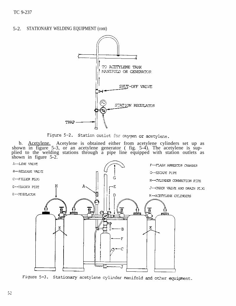
5-2. STATIONARY WELDING EQUIPMENT (cont)
b. Acetylene. Acetylene is obtained either from acetylene cylinders set up asshown in figure 5-3, or an acetylene generator ( fig. 5-4). The acetylene is sup-plied to the welding stations through a pipe line equipped with station outlets asshown in figure 5-2.
5-2

TC 9-237
5-3

TC 9-237
5-3. PORTABLE WELDING EQUIPMENT
The portable oxyacetylene welding outfit consists of an oxygen cylinder and anacetylene cylinder with attached valves, regulators, gauges, and hoses (fig. 5-5).This equipment may be temporarily secured on the floor or mounted on an all weldedsteel truck. The trucks are equipped with a platform to support two large sizecylinders. The cylinders are secured by chains attached to the truck frame. Ametal toolbox, welded to the frame, provides storage space for torch tips, gloves,fluxes, goggles, and necessary wrenches.
5-4. ACETYLENE GENERATOR
NOTEAcetylene generator equipment is not a standardincluded in this manual for information only.
item of issue and is
a. Acetylene is a fuel gas composed of carbon and hydrogen. (C7H 2), generated bythe action of calcium carbide, a gray stonelike substance, and water in a generat-ing unit. Acetylene is colorless, but has a distinctive odor that can be easilydetected.
b. Mixtures of acetylene and air, containing from 2 to 80 percent acetylene byvolume , will explode when ignited. However, with suitable welding equipment and
5-4

TC 9-237
proper precautions, acetylene can be safely burned with oxygen for heating, weld-ing, and cutting putposes.
Acetylene, when burned with oxygen, produces an oxyacetylene flame withinner; cone tip temperatures of approximately 6300 0F (3482 0C), for an oxidizingflame; 5850 0F (3232 0C) for a neutral flame; and 5700 0F (3149 0C) for acarburizing flame.
d. The generator shown in figure 5–4 is a commonly used commercial type. Asingle rated 300-lb generator uses 300 lb of calcium carbide and 300 gal. of water.This amount of material will generate 4.5 cu ft of acetylene per pound; the outputfor this load is approximately 300 cu ft per hour for 4.5 hours. A double ratedgenerator uses 300 lb of finer sized calcium carbide fed through a special hopperand will deliver 600 cu ft of acetylene per hour for 2.5 hours.
CAUTIONSince considerable heat is given off during the reaction, precautionsmust be taken to prevent excessive pressures in the generator whichmight cause fires or explosions.
e. In the operation of the generator, the calcium carbide is added to the waterthrough a hopper mechanism at a rate which will maintain a working pressure of
equipment. A sludge, consisting of hydrated or slaked lime, settles in the bottomapproximately 15 psi (103.4 kPa). A pressure regulator is a built-in part of this
of the generator and is removed-by5-5. ACETYLENE CYLINDERS
Acetylene, stored in a free(103.4 kPa), can break down
means of a sludge outlet.
state under pressure greater than 15 psifrom heat or shock, and possibly explode.
Under pressure of 29.4 psi (203 kPa), acetylene becomes self- explosive, and a slight shock can cause it to explode spontaneously.
CAUTIONAlthough acetylene is nontoxic, it is an anesthetic, and if present ina sufficiently high concentration, is an asphyxiant in that it replac–es oxygen and can produce suffocation.
a. Acetylene is a colorless, flammable gas composed of carbon and hydrogen,manufactured by the reaction of water and calcium carbide. It is slightly lighterthan air. Acetylene burns in the air with an intensely hot, yellow, luminous,smoky flare.
b. Although acetylene is stable under low pressure, if compressed to 15 psi(103.4 kPa), it becomes unstable. Heat or shock can cause acetylene under pressureto explode. Avoid exposing filled cylinders to heat, furnaces, radiators, openfires, or sparks (from a torch). Avoid striking the cylinder against other objectsand creating sparks. To avoid shock when transporting cylinders, do not drag,roll, or slide them on their sides. Acetylene can be compressed into cylinderswhen dissolved in acetone at pressures up to 250 psi (1724 kPa) .
c. For welding purposes, acetylene is contained in three common cylinders withcapacities of 1, 60, 100, and 300 cu ft. Acetylene must not be drawn off in vol–umes greater than 1/7 of the cylinder’s rated capacity.
5-5

TC 9-237
5-5. ACETYLENE CYLINDERS (cont)
d. In order to decrease the size of the open spaces in the cylinder, acetylenecylinders (fig. 5-6) are filled with porous materials such as balsa wood, charcoal,corn pith, or portland cement. Acetone, a colorless, flammable liquid, is added tothe cylinder until about 40 percent of the porous material is saturated. The po-rous material acts as a large sponge which absorbs the acetone, which then absorbsthe acetylene. In this process, the volume of acetone increases as it absorbs theacetylene, while acetylene, being a gas, decreases in volume.
CAUTIONDo not fill acetylene cylinders at a rate greater than 1/7 of theirrated capacity, or about 275 cu ft per hour. To prevent drawing offof acetone and consequent impairment of weld quality and damage to thewelding equipment, do not draw acetylene from a cylinder at continuousrates in volumes greater than 1/7 of the rated capacity of the cylin-der, or 32.1 cu ft per hour. When more than 32.1 cu ft per hour arerequired, the cylinder manifold system must be used.
e. Acetylene cylinders are equipped with safety plugs (fig. 5-6 ) which have asmall hole through the center. This hole is filled with a metal alloy which meltsat approximately 212 0F (100 0C), or releases at 500 psi (3448 kPa). When a cylin-der is overheated, the plug will melt and permit the acetylene to escape beforedangerous pressures can be developed. The plug hole is too small to premit a flameto burn back into the cylinder if escaping acetylene is ignited.
5-6

TC 9–237
f . The brass acetylene cylinder valves have squared stainless steel valvestems. These stems can be fitted with a cylinder wrench and opened or closed whenthe cylinder is in use. The outlet of the valve is threaded for connection to anacetylene pressure regulator by means of a union nut. The regulator inlet connec-tion gland fits against the face of the threaded cylinder connection, and the unionnut draws the two surfaces together. Whenever the threads on the valve connectionsare damaged to a degree that will prevent proper assembly to the regulator, thecylinder should be marked and set aside for return to the manufacturer.
WARNINGAcetylene which may accumulate in a storage room or in a confinedspace is a fire arid explosion hazard. All acetylene cylinders shouldbe checked, using a soap solution, for leakage at the valves and safe-ty fuse plugs.
g. A protective metal cap (fig. 5-6) screws onto the valve to prevent damageduring shipment or storage.
h. Acetylene, when used with oxygen, produces the highest flame temperature ofany of the fuel gases. It also has the most concentrated flame, but produces lessgross heat of combustion than the liquid petroleum gases and the synthetic gases.
5-6. OXYGEN AND ITS PRODUCTION
a. General. Oxygen is a colorless, tasteless, odorless gas that is slightlyheavier than air. It is nonflammable but will support combustion with other ele-ments . In its free state, oxygen is one of the most common elements. The atmo-sphere is made up of approximately 21 parts of oxygen and 78 parts of nitrogen, theremainder being rare gases. - ferrous metals, discoloration of copper,Rusting ofand the corrosion of aluminum are all due to the action of atmospheric oxygen,known as oxidation.
b. Production of Oxygen. Oxygen is obtained commercially either by the liquidair process or by the electrolytic process.
(1) In the liquid air process, air is compressed and cooled to a point wherethe gases become liquid. As the temperature of the liquid air rises, nitrogen in agaseous form is given off first, since its boiling point is lower than that ofliquid oxygen. These gases, having been separated, are then further purified andcompressed into cylinders for use. The liquid air process is by far the most wide–ly used to produce oxygen.
(2) In the electrolytic process, water is broken down into hydrogen and oxy–gen by the passage of an electric current. The oxygen collects at the positiveterminal and the hydrogen at the negative terminal. Each gas is collected andcompressed into cylinders for use.
5-7
TC 9-237
5-7. OXYGEN CYLINDER
CAUTIONAlways refer to oxygen as oxygen, never as air. Combustibles should bekept away from oxygen, including the cylinder, valves, regulators, andother hose apparatus. Oxygen cylinders and apparatus should not behandled with oily hands or oily gloves. Pure oxygen will support andaccelerate combustion of almost any material, and is especially danger-ous in the presence of oil and grease. Oil and grease in the presence ofoxygen may spontaneously ignite and burn violently or explode. Oxygenshould never be used in any air tools or for any of the purposes forwhich compressed air is normally used.
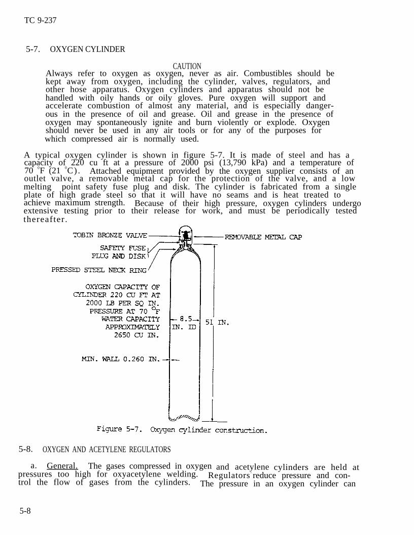
A typical oxygen cylinder is shown in figure 5-7. It is made of steel and has acapacity of 220 cu ft at a pressure of 2000 psi (13,790 kPa) and a temperature of70 0F (21 0C). Attached equipment provided by the oxygen supplier consists of anoutlet valve, a removable metal cap for the protection of the valve, and a lowmelting point safety fuse plug and disk. The cylinder is fabricated from a singleplate of high grade steel so that it will have no seams and is heat treated toachieve maximum strength. Because of their high pressure, oxygen cylinders undergoextensive testing prior to their release for work, and must be periodically testedthereafter .
5-8. OXYGEN AND ACETYLENE REGULATORS
and acetylenea. General. The gases compressed in oxygenpressures too high for oxyacetylene welding. Regulators - reduce pressure and con-trol the flow of gases from the cylinders. The pressure in an oxygen cylinder can
5-8
cylinders are held at

TC 9-237
be as high as 2200 psi (15,169 kPa), which must be reduced to a working pressure of1 to 25 psi (6.90 to 172.38 kPa). The pressure of acetylene in an acetylene cylin-der can be as high as 250 psi (1724 kPa) and must be reduced to a working pressureof from 1 to 12 psi (6.90 to 82.74 kPa). A gas pressure regulator will automatical-ly deliver a constant volume of gas to the torch at the adjusted working pressure.
NOTEThe regulators for oxygen, acetylene, and liquid petroleum fuel gasesare of different construction. They must be used only for the gas forwhich they were designed.
Most regulators in use are either the single stage or the two stage type. Checkvalves must be installed between the torch hoses and the regulator to prevent flash-back through the regulator.
b. Single Stage Oxygen Regulator. The single stage oxygen regulator reducesthe cylinder pressure of a gas to a working pressure in one step. The single stageoxygen regulator mechanism (fig. 5-8) has a nozzle through which the high pressuregas passes, a valve seat to close off the nozzle, and balancing springs. Sometypes have a relief valve and an inlet filter to exclude dust and dirt. Pressuregauges are provided to show the pressure in the cylinder or pipe line and the work-ing pressure.
5-9

TC 9–237
5-8. OXYGEN AND ACETYLENE REGULATORS (cont)
NOTEIn operation, the working pressure falls as the cylinder pressurefalls, which occurs gradually as gas is withdrawn. For this reason,the working pressure must be adjusted at intervals during weldingoperations when using a single stage oxygen regulator.
The oxygen regulator controls and reduces the oxygen pressure from any standardcommercial oxygen cylinder containing pressures up to 3000 psi. The high pressuregauge, which is on the inlet side of the regulator, is graduated from 0 to 3000p s i . The low or working pressure gauge, which is on the outlet side of the regula-tor, is graduated from O to 500 psi.
c. Operation of Single Stage Oxygen Regulator.
(1) The regulator consists of a flexible diaphragm, which controls a needlevalve between the high pressure zone and the working zone, a compression spring,and an adjusting screw, which compensates for the pressure of the gas against thediaphragm. The needle valve is on the side of the diaphragm exposed to high gaspressure while the compression spring and adjusting screw are on the opposite sidein a zone vented to the atomsphere.
(2) The oxygen enters the regulator through the high pressure inlet connec-tion and passes through a glass wool filter, which removes dust and dirt. Theseat, which closes off the nozzle, is not raised until the adjusting screw isturned in. Pressure is applied to the adjusting spring by turning the adjustingscrew, which bears down on the rubber diaphragm. The diaphragm presses downward onthe stirrup and overcomes the pressure on the compensating spring. When the stir-rup is forced downward, the passage through the nozzle is open. Oxygen is thenallowed to flow into the low pressure chamber of the regulator. The oxygen thenpasses through the regulator outlet and the hose to the torch. A certain set pres-sure must be maintained in the low pressure chamber of the regulator so that oxygenwill continue to be forced through the orifices of the torch, even if the torchneedle valve is open. This pressure is indicated on the working pressure gage ofthe regulator, and depends on the position of the regulator adjusting screw. Pres-sure is increased by turning the adjusting screw to the right and decreased byturning this screw to the left.
(3) Regulators used at stations to which gases are piped from an oxygen mani-fold, acetylene manifold, or acetylene generator have only one low pressure gagebecause the pipe line pressures are usually set at 15 psi (103.4 kPa) for acetyleneand approximately 200 psi (1379 kPa) for oxygen. The two stage oxygen regulator(fig. 5–9) is similar in operation to the one stage regulator, but reduces pressurein two steps. On the high pressure side, the pressure is reduced from cylinderpressure to intermediate pressure. On the low pressure side the pressure is re-duced from intermediate pressure to work pressure. Because of the two stage pres-sure control, the working pressure is held constant, and pressure adjustment duringwelding operations is not required.
5-10

TC 9-237
e. Acetylene Regulator.
CAUTIONAcetylene should never be used at pressures exceeding 15 psi (103.4kPa).
This regulator controls the acetylene pressure from any standard commercial cylin-der containing pressures up to 500 psi (3447.5 kPa). The acetylene regulator de-sign is generally the same as that of the oxygen regulator, but will not withstandsuch high pressures. The high pressure gage, on the inlet side of the regulator,is graduated from O to 500 psi (3447.5 kPa). The low pressure gage, on the outletside of the regulator, is graduated from O to 30 psi (207 kPa). Acetylene shouldnot be used at pressures exceeding 15 psi (103.4 kPa).
5-9. OXYACETYLENE WELDING TORCH
a. General. The oxyacetylene welding torch is used to mix oxygen and acetylenein definite proportions. It also controls the volume of these gases burning at thewelding tip, which produces the required type of flame. The torch consists of ahandle or body which contains the hose connections for the oxygen and the fuelgas. The torch also has two needle valves, one for adjusting the flew of oxygenand one for acetylene, and a mixing head. In addition, there are two tubes, onefor oxygen, the other for acetylene; inlet nipples for the attachment of hoses; atip; and a handle. The tubes and handle are of seamless hard brass, copper-nickelalloy, stainless steel. For a description and the different sized tips, see para-graph 5-10.
b. Types of Torches. There are two general types of welding torches; the lowpressure or injector type, and the equal pressure type.
5-11

TC 9-237
5-9. OXYACETYLENE WELDING TORCH (cont)
(1) In the low pressure or injector type (fig. 5-10), the acetylene pressureis less than 1 psi (6.895 kPa). A jet of high pressure oxygen is used to produce asuction effect to draw in the required amount of acetylene. Any change in oxygenflow will produce relative change in acetylene flow so that the proportion of thetwo gases remains constant. This is accomplishd by designing the mixer in thetorch to operate on the injector principle. The welding tips may or may not haveseparate injectors designed integrally with each tip.
(2) The equal pressure torch (fig. 5-11) is designed to operate with equalpressures for the oxygen and acetylene. The pressure ranges from 1 to 15 psi(6.895 to 103.4 kPa). This torch has certain advantages over the loW pressuretype. It can be more readily adjusted, and since equal pressures are used for eachgas, the torch is less susceptible to flashbacks.
5-12

TC 9-237
5-10.
a.copperstylesnumber
WELDING TIPS AND MIXERS
The welding tips (fig. 5-10 and 5-11) are made of hard drawn electrolyticor 95 percent copper and 5 percent tellurium. They are made in variousand types, some having a one-piece tip either with a single orifice or aof orifices. The diameters of the tip orifices differ in order to control
the quantity of heat and the type of flame. These tip sizes are designated bynumbers which are arranged according to the individual manufacturer’s system.Generally, the smaller the number, the smaller the tip orifice.
b. Mixers (fig. 5-10 and 5-11) are frequently provided in tip tier assemblieswhich assure the correct flow of mixed gases for each size tip. In this tip mixerassembly, the mixer is assembled with the tip for which it has been drilled andthen screwed onto the torch head. The universal type mixer is a separate unitwhich can be used with tips of various sizes.
5-11. HOSE
a. The hoses used to make the connection betwenare made especially for this purpose.
(1) Hoses are built to withstand high internal
the regulators and the torch
pressures.
(2) They are strong, nonporous, light, and flexible to permit easy manipula-tion of the torch.
(3) The rubber used in the manufacture of hose is chemically treated to re-move free sulfur to avoid possible spontaneous combustion.
(4) The hose
Hose shouldanother .
is not impaired by prolonged
CAUTIONnever be used for one gas if
exposure to light.
it was previously used for
b. Hose identification and composition.
(1) In North America, the oxygen hose is green and the acetylene hose isred. In Europe, blue is used for oxygen and orange for acetylene. Black is some-times also used for oxygen.
(2) The hose is a rubber tube with braided or wrapped cotton or rayon rein-forcements and a rubber covering. For heavy duty welding and cutting operations,requiring 1/4- to l/2-in. internal diameter hose, three to five plies of braided orwrapped reinforcements are used. One ply is used in the 1/8- to 3/16-in. hose forlight torches.
c . Hoses are provided with connections at each end so that they may be connect-ed to their respective regulator outlet and torch inlet connections. To prevent adangerous interchange of acetylene and oxygen hoses, all threaded fittings used forthe acetylene hook up are left hand, and all threaded fittings for the oxygen hookup are right hand. Notches are also placed on acetylene fittings to prevent amixup .
5-13

TC 9-237
5-11. HOSE (cont)
d. Welding and cutting hoses are obtainable as a single hose for each gas orwith the hoses bonded together along their length under a common outer rubber jack-e t . The latter type prevents the hose from kinking or becoming tangled during thewelding operation.
5-12. SETTING UP THE EQUIPMENT
WARNINGAlways have suitable fire extinguishing equipment at hand when doingany welding.
When setting up welding and cutting equipment, it is important that all operationsbe performed systematically in order to avoid mistakes and possible trouble. Thesetting up procedures given in a through d below will assure safety to the operatorand the apparatus.
a. Cylinders.
WARNINGDo not stand facing cylinder valve outlets of oxygen, acetulene, orother compressed gases when opening them.
(1) Place the oxygen and the acetylene cylinders on a level floor (if theyare not mounted on a truck), and tie them firmly to a work bench, post, wall, orother secure anchorage to prevent their being knocked or pulled over.
(2) Remove the valve protecting caps.
(3) “Crack” both cylinder valves by opening first the acetylene and then theoxygen valve slightly for an instant to blow out any dirt or foreign matter thatmay have accumulated during shipment or storage.
(4) Close the valves and wipe the connection seats with a clean cloth.
b. Pressure Regulators.
(1) Check the regulator fittings for dirt and obstructions. Also checkthreads of cylinders and regulators for imperfections.
(2) Connect the acetylene regulator to the acetylene regulator and the oxygenregulator to the oxygen cylinder. Use either a regulator wrench or a close fittingwrench and tighten the connecting nuts sufficiently to prevent leakage.
(3) Check hose for burns, nicks, and bad fittings.
(4) Connect the red hose to the acetylene regulator and the green hose to theoxygen regulator. Screw the connecting nuts tightly to insure leakproof seating.Note that the acetylene hose connection has left hand threads.
5-14

TC 9-237
WARNINGIf it is necessary to blow out the acetylene hose, do it in a wellventilated place which is free of sparks, flame, or other sources ofignition.
(5) Release the regulator screws to avoid damage to the regulators and gag-es. Open the cylinder valves slowly. Read the high pressure gages to check thecylinder gas pressure. Blow out the oxygen hose by turning the regulator screw inand then release the regulator screw. Flashback suppressors must be attached tothe torch whenever possible.
c. Torch. Connect the red acetylene hose to the torch needle valve which isstamped “AC or flashback suppressor”. Connect the green oxygen hose to the torchneedle valve which is stamped “OX or flashback suppressor”. Test all hose connec–tions for leaks at the regulators and torch valves by turning both regulators’screws in with the torch needle valves closed. Use a soap and water solution totest for leaks at all connections. Tighten or replace connections where leaks arefound . Release the regulator screws after testing and drain both hose lines byopening the torch needle valves. Slip the tip nut over the tip, and press the tipinto the mixing head. Tighten by hand and adjust the tip to the proper angle.Secure this adjustment by tightening with the tip nut wrench.
WARNINGPurge both acetylene and oxygen lines (hoses) prior to ignitingtorch. Failure to do this can cause serious injury to personnel anddamage to the equipment.
d. Adjustment of Working Pressure. Adjust the acetylene working pressure byopening the acetylene needle valve on the torch and turning the regulator screw tothe right. Then adjust the acetylene regulator to the required pressure for thetip size to be used (tables 5-1 and 5-2). Close the needle valve. Adjust the oxy-gen working pressure in the same manner.
5-15

TC 9-237
5-12. SETTING UP THE WELDING EQUIPMENT (cont)
5-13. SHUTTING DOWN WELDING APPARATUS
a. Shut off the gases. Close the acetylene valve first, then the oxygen valveon the torch. Then close the acetylene and oxygen cylinder valves.
b. Drain the regulators and hoses by the following procedures:
(1) Open the torch acetylene valve until the gas stops flowing and the gaugesread zero, then close the valve.
(2) Open the torch oxygen valve to drain the oxygen regulator and hose. Whengas stops flowing and the gauges read zero, close the valve.
(3) When the above operations are performed properly, both high and low pres-sure gauges on the acetylene and oxygen regulators will register zero.
c. Release the tension on both regulator screws by turning the screws to theleft until they rotate freely.
d. Coil the hoses without kinking them and suspend them on a suitable holder orhanger. Avoid upsetting the cylinders to which they are attached.
5-14. REGULATOR MALFUNCTIONS AND CORRECTIONS
a. Leakage of gas between the regulator seat and the nozzle is the principalproblem encounter with regulators. It is indicated by a gradual increase inpressure on the working pressure gauge when the adjusting screw is fully releasedor is in position after adjustment. This defect, called “creeping regulator”, iscaused by bad valve seats or by foreign matter lodged between the seat and thenozzle.
5-16

TC 9-237
WARNINGRegulators with leakage of gas between the regulator seat and thenozzle must be replaced immediately to avoid damage to other parts ofthe regulator or injury to personnel. With acetylene regulators, thisleakage is particularity dangerous because acetylene at high pressurein the hose is an explosion hazard.
b. The leakage of gas, as described. above, can be corrected as outlined below:
(1) Remove and replace the seat if it is worn , cracked, or otherwise damaged.
(2) If the malfunction is caused by fouling with dirt or other foreign mat-ter, clean the seat and nozzle thoroughly and blow out any dust or dirt in thevalve chamber.
c. The procedure for removing valve seats and nozzles will vary with the makeor design.
d. Broken or buckled gage tubes and distorted or buckled diaphragms are usuallycaused by backfire at the torch, leaks across the regulator seats, or by failure torelease the regulator adjusting screw fully before opening the cylinder valves.
e. Defective bourdon tubes in the gages are indicated by improper action of thegages or by escaping gas from the gage case. Gages with defective bourdon tubesshould be removed and replaced with new gages. Satisfactory repairs cannot be madewithout special equipment.
f . Buckled or distorted diaphragms cannot be adjusted properly and should bereplaced with new ones. Rubber diaphragms can be replaced easily by removing thespring case with a vise or wrench. Metal diaphragms are sometimes soldered to thevalve case and their replacement is a factory or special repair shop job. Suchrepairs should not be attempted by anyone unfamiliar with the work.
5-15.
a .
TORCH MALFUNCTIONS AND CORRECTIONS
WARNINGDefects in oxyacetylene welding torches which are sources of gas leaksmust be corrected immediately, as they may result in flashbacks orbackfires, with resultant injury to the operator and/or damage to thewelding apparatus.
General. Improved functioning of welding torches is usually due to one ormore of the following causes: leaking valves, leaks in the mixing head seat, scoredor out-of-round welding tip orifices, clogged tubes or tips, and damaged inletconnection threads. Corrective measures for these common torch defects are de-scribed below.
b. Leaking Valves.
(1) Bent or worn valve stems should be replaced and damaged seats should berefaced.
5-17

TC 9-237
(2) Loose packing may be corrected by tightening the packing nut or by in-stalling new packing and then tightening the packing nut.
CAUTIONThis work should be done by the manufacturer because special reamersare required for trueing these seats.
c. Leaks in the Mixing Heads. These are indicated by popping out of the flameand by emission of sparks from the tips accompanied by a squealing noise. Leaks inthe mixing head will cause improper mixing of the oxygen and acetylene causingflashbacks. A flashback causes the torch head and handle to suddenly become veryhot . Repair by reaming out and trueing the mixing head seat.
d. Scored or Out-of-Round Tip Orifices. Tips in this condition cause the flameto be irregular and must be replaced.
e. Clogged Tubes and Tips.
(1) Carbon deposits caused by flashbacks or backfire, or the presence offoreign matter that has entered the tubes through the hoses will clog tubes. Ifthe tubes or tips are clogged, greater working pressures will be needed to producethe flame required. The flame produced will be distorted.
(2) The torch should be disassembled so that the tip, mixing head, valves,and hose can be cleaned and cleaned out with compressed air at a pressure of 20 to 30psi (137.9 to 206.85 kPa).
(3) The tip and mixing head should be cleaned either with a cleaning drill orwith soft copper or brass wire , and then blown out with compressed air. The clean-ing drills should be approximately one drill size smaller than the tip orifice toavoid enlarging the orifice during cleaning.
WARNINGDamages inlet connection threads may cause fires by ignition of theleaking gas, resulting in injury to the welding operator and/or damageto the equipment.
f . Damaged Inlet Connection Threads. Leaks due to damaged inlet connectionthreads can be detected by opening the cylinder valves and keeping the needlevalves closed. Such leaks will cause the regulator pressure to drop. Also, if thethreads are damaged, the hose connection at the torch inlet will be difficult orimpossible to tighten. To correct this defect, the threads should be recut and thehose connections thoroughly cleaned.
5-18

TC 9-237
Section II. OXYACETYLENE CUTTING EQUIPMENT
5-16. CUTTING TORCH AND OTHER CUTTING EQUIPMENT
a. The cutting torch (fig. 5-12), like the welding torch, has a tube for oxygenand one for acetylene. In addition, there is a tube for high pressure oxygen,along with a cutting tip or nozzle. The tip (fig. 5-13) is provided with a centerhole through which a jet of pure oxygen passes. Mixed oxygen and acetylene passthrough holes surrounding the center holes for the preheating flames. The numberof orifices for oxyacetlylene flames ranges from 2 to 6, depending on the purposefor which the tip is used. The cutting torch is controlled by a trigger or leveroperated valve. The cutting torch is furnished with interchangeable tips for cut-ting steel from less than 1/4 in. (6.4 mm) to more than 12.0 in. (304.8 mm) inthickness.
5-19

TC 9–237
5-16. CUTTING TORCH AND OTHER CUTTING EQUIPMENT (cont)
b. A cutting attachment fitted to a welding torch in place of the welding tipis shown in figure 5-14.
c. In order to make uniformly clean cuts on steel plate, motor driven cuttingmachines are used to support and guide the cutting torch. Straight line cutting orbeveling is acccomplished by guiding the machine along a straight line on steeltracks. Arcs and circles are cut by guiding theabout a central point.5-15 and 5-16.
machine with a radius rod pivotedTypical cutting machines in operation are shown in figures
5-20

TC 9-237
d. There is a wide variety of cutting tip styles and sizes available to suitvarious types of work. The thickness of the material to be cut generally governsthe selection of the tip. The cutting oxygen pressure, cutting speed, and preheat-ing intensity should be controlled to produce narrow, parallel sided kerfs. Cutsthat are improperly made will produce ragged, irregular edges with adhering slag atthe bottom of the plates. Table 5-3 identifies cutting tip numbers, gas pressures,and hand-cutting speeds used for cutting mild steel up to 12 in. (304.8 mm) thick.
5-21

TC 9-237
5-17. OPERATION OF CUTTING EQUIPMENT
Attach the required cutting tip to the torch and adjust the oxygen and acety-lene pressures in accordance with table 5-3.
NOTEThe oxygen and acetylene gas pressure settings listed are only approxi-mate. In actual use, pressures should be set to effect the best metalcut .
b. Adjust the preheating flame to neutral.
c. Hold the torch so that the cutting oxygen lever or trigger can be operatedwith one hand. Use the other hand to steady and maintain the position of the torchhead to the work. Keep the flame at a 90 degree angle to work in the direction oftravel . The inner cones of the preheating flames should be about 1/16 in. (1.6 mm)above the end of the line to be cut. Hold this position until the spot has beenraised to a bright red heat, and then slowly open the cutting oxygen valve.
d. If the cut has been started properly, a shower of sparks will fall from theopposite side of the work. Move the torch at a speed which will allow the cut tocontinue penetrating the work. A good cut will be clean and narrow.
e. When cutting billets, round bars, or heavy sections, time and gas are savedif a burr is raised with a chisel at the point where the cut is to start. Thissmall portion will heat quickly and cutting will start immediately. A welding rodcan be used to start a cut on heavy sections. When used, it is called a startingrod.
Section III. ARC WELDING EQUIPMENT AND ACCESSORIES
5-18. GENERAL
In electric welding processes , an arc is produced between an electrode and the workpiece (base metal). The arc is formed by passing a current between the electrodeand the workpiece across the gap. The current melts the base metal and the elec-trode (if the electrode is a consumable type), creating a molten pool. On solidify-ing, the weld is formal. An alternate method employs a nonconsumable electrode,such as a tungsten rod. In this case, the weld is formed by melting and solidify-ing the base metal at the joint. In some instances, additional metal is required,and is added to the molten pool from a filler rod.
Electrical equipment required for arc welding depends on the source from which theelectric power is obtained. If the power is obtained from public utility lines,one or more of the following devices are required: transformers (of which thereare several types), rectifiers, motor generators, and control equipment. If publicutility power is not available, portable generators driven by gasoline or dieselengines are used.
5-22

TC 9-237
5-19. DIRECT CURRENT ARC WELDING MACHINES
a. The direct current welding machine has a heavy duty direct5-17). The generators are made in six standardized ratingsposes as described below:
current generatorfor general pur-
(1) The machines rated 150 and 200 amperes, 30 volts, are used for lightshielded metal-arc welding and for gas metal-arc welding. They are also used forgeneral purpose job shop work.
(2) The machines rated 200, 300, and 400 amperes, 40 volts, used forgeneral welding purposes by machine or manual application.
(3) Machines rated 600 amperes, 40 volts, are used for submerged arc weldingand for carbon-arc welding.
b. The electric motors must commonly used to drive the welding generators are220/440 volts, 3 phase, 60 cycle. The gasoline and diesel engines should have arated horsepower in excess of the rated output of the generator. This will allowfor the rated overload capacity of the generator and for the power required tooperate the accessories of the engine. The simple equarion HP = 1.25P/746 can beused; HP is the engine horsepower and P is the generator rating in watts. Forexapmle, a 20 horsepower engine would be used to drive a welding generator with arated 12 kilowatt output.
5-23

TC 9-237
5-19. DIRECT CURRENT ARC WELDING MACHINES (cont)
c. In most direct current welding machines, the generator is of the variablevoltage type, and is arranged so that the voltage is automatically adjusted to thedemands of the arc. However, the voltage may be set manually with a rheostat.
d. The welding current amperage is also manually adjustable, and is set bymeans of a selector switch or series of plug receptacles. In either case, thedesired amperage is obtained by tapping into the generator field coils. When bothvoltage and amperage of the welding machine are adjustable, the machine is known asdual control type. Welding machines are also manufactured in which current con-trols are maintained by movement of the brush assembly.
e. A direct current welding machine is described in TM 5-3431-221-15, and isillustrated in figure 5-18.
f . A maintenance schedule should be set up to keep the welding machine in goodoperating condition. The machine should be thoroughly inspected every 3 months andblown free of dust with clean, dry, compressed air. At least once each year, thecontacts of the motor starter switches and the rheostat should be cleaned and re-placed if necessary. Brushes should be inspected frequently to see if they aremaking proper contact on the commutator, and that they move freely in the brushholders. Clean and true the commutator with sandpaper or a commutator stone if itis burned or roughened. Check the bearings twice a year. Remove all the oldgrease and replace it with new grease.
5-24

TC 9-237
g. Direct current rectifier type welding machines have been designed with cop-per oxide, silicon, or selenium dry plates. These machines usually consist of atransform to reduce the power line voltage to the required 220/440 volts, 3phase, 60 cycle input current; a reactor for adjustment of the current; and a recti-fier to change the alternating current to direct current. Sometimes another reac-tor is used to reduce ripple in the output current.
5-20. ALTERNATING CURRENT ARC WELDING MACHINES
a. Most of the alternating current arc welding machines in use are of the sin-gle operator, static transformer type (fig. 5-19). For manual operation in indus-trial applications, machines having 200, 300, and 400 amphere ratings are the sizesin general use. Machines with 150 ampere ratings are sometimes used in light indus-trial, garage and job shop welding.
b. The transformers are generally equipped with arc stabilizing capacitors.Current control is provided in several ways. One such method is by means of anadjustable reactor in the output circuit of the transformer. In other types, inter-nal reactions of the transformer are adjustable. A handwheel, usually installed onthe front or the top of the machine, makes continuous adjustment of the outputcurrent, without steps, possible.
c. The screws and bearings on machines with screw type adjustments should belubricated every 3 months. The same lubrication schedule applies to chain drives.Contacts, switches, relays, and plug and jack connections should be inspected every3 months and cleaned or replaced as required. The primary input current at no loadshould be measured and checked once a year to ensure the power factor connectingcapacitors are working, and that input current is as specified on the nameplate orin the manufacturer’s instruction book.
5-25

TC 9-237
5-21. GAS TUNGSTEN-ARC WELDING (GTAW) EQUIPMENT (TIG)
a. General. In tungsten inert gas (TIG) welding, (also known as GTAW), an arcis struck between a virtually nonconsumable tungsten electrode and the workpiece.The heat of the arc causes the edges of the work to melt and flow together. Fillerrod is often required to fill the joint. During the welding operation, the weldarea is shielded from the atmosphere by a blanket of inert argon gas. A steadystream of argon passes through the torch, which pushes the air away from the weld-ing area and prevents oxidation of the electrode, weld puddle, and heat affectedzone.
b. Equipment.
(1) The basic equipment requirements for manual TIG welding are shown infigure 5-20. Equipment consists of the welding torch plus additional apparatus tosupply electrical power, shielding gas, and a water inlet and outlet. Also, person-al protective equipment should be worn to protect the operator from the arc raysduring welding operations.
NOTEDifferent types of TIG welding equipment are available through normalsupply channels. Water-cooled torches and air-cooled torches are bothavailable. Each type carries different amperage ratings. Consult theappropriate manual covering the type torch used.
(2) Argon is supplied in steel cylinders containing approximately 330 cu ftat a pressure to 2000 psi (13,790 kPa). A single or two stage regulator may beused to control the gas flow. A specially designed regulator containing aflowmeter, as shown in figure 5-21, may be used. The flowmeter provides betteradjustment via flow control than the single or two stage regulator and is calibrat-ed in cubic feet per hour (cfh). The correct flow of argon to the torch is set byturning the adjusting screw on the regulator. The rate of flow depends on the kindand thickness of the metal to be welded.
5-26

TC 9-237
(3)directed
Blanketing of the weld area is provided by a steady flow of argon gasthrough the welding torch (fig. 5-22). Since argon is slightly more than
1-1/3 times as heavy as air, it pushes the lighter air molecules aside, effectivelypreventing oxidation of the welding electrode, the molten weld puddle, and the heataffected zone adjacent to the weld bead.
5-27

TC 9-237
5-21. GAS TUNGSTEN-ARC WELDING (GTAW) EQUIPMENT (TIG) (cent)
(4) The tremendous heat of the arc and the high current often used usuallynecessitate water cooling of the torch and power cable ( fig. 5-22). The coolingwater must be clean; otherwise, restricted or blocked passages may cause excessiveoverheating and damage to the equipment. It is advisable to use a suitable waterstrainer or filter at the water supply source. If a self-contained unit is used,such as the one used in the field (surge tank) where the cooling water is recircu-lated through a pump, antifreeze is required if the unit is to be used outdoorsduring the winter months or freezing weather. Some TIG welding torches requireless than 55 psi (379 kPa) water pressure and will require a water regulator ofsome type. Check the operating manual for this information.
c. Nomenclature of Torch (fig. 5-22).
(1) Cap. Prevents the escape of gas from the top of the torch and locks theelectrode in place.
(2) Col le t . Made of copper; the electrode fits inside and when the cap istightened, it squeezes against the electrode and leeks it in place.
(3) Gas orifice nut. Allows the gas to escape.
(4) Gas nozzle. Directs the flew of shielding gas onto the weld puddle. Twotypes of nozzles are used; the one for light duty welding is made of a ceramicmaterial, and the one for heavy duty welding is a copper water-cooled nozzle.
(5) Hoses. Three plastic hoses, connected inside the torch handle, carrywater, gas, and the electrode power cable.
5-22. GAS METAL-ARC WELDING (GMAW) EQUIPMENT
a. General. GMAW is most commonly referred to as “MIG” welding, and the follow-ing text will use “MIG” or “MIG welding” when referring to GMAW. MIG welding is aprocess in which a consumable, bare wire electrode is fed into a weld at a con-trolled rate of speed, while a blanket of inert argon gas shields the weld zonefrom atmospheric contamination. In addition to the three basic types of metaltransfer which characterize the GMAW process, there are several variationsof significance.
(1) Pulsed spray welding. Pulsed spray welding is a variation of the MIGwelding process that is capable of all–position welding at higher energy levelsthan short circuiting arc welding. The power source provides two current levels; asteady “background” level, which is too low to produce spray transfer; and a“pulsed peak” current, which is superimposed upon the background current at a regu-lated interval. The pulse peak is well above the transition current, and usuallyone drop is transferred during each pulse. The combination of the two levels ofcurrent produces a steady arc with axial spray transfer at effective welding cur-rents below those required for conventional spray arc welding. Because the heatinput is lower, this variation in operation is capable of welding thinner sectionsthan are practical with the conventional spray transfer.
(2) Arc spot welding. Gas metal arc spot welding is a method of joiningsimilar to resistance spot welding and riveting. A variation of continuous gas
5-28

TC 9-237
metal arc welding, the process fuses two pieces of sheet metal together by penetrat-ing entirely through one piece into the other. No joint preparation is requiredother than cleaning of the overlap areas. The welding gun remains stationary whilea spot weld is being made. Mild steel, stainless steel, and aluminum are commonlyjoined by this method.
(3) Electrogas welding. The electrogas (EG) variation of the MIG weldingprocess is a fully automatic, high deposition rate method for the welding of butt,corner, and T-joints in the vertical position. The eletrogas variation essential-ly combines the mechanical features of electroslag welding (ESW) with the MIG weld-ing process. Water-coded copper shoes span the gap between the pieces being weld-ed to form a cavity for the molten metal. A carriage is mounted on a verticalcolumn; this combination provides both vertical and horizontal movement. Weldinghead, controls, and electrode spools are mounted on the carriage. Both the car-riage and the copper shoes move vertically upwards as welding progresses. Thewelding head may also be oscillated to provide uniform distribution of heat andfiller metal. This method is capable of welding metal sections of from 1/2 in. (13mm) to more than 2 in. (5.08 an)of 35 to 46 lb (16 to 21 kg) per
b. MIG Equipment.
in thickness in a single pass. Deposition rateshour per electrode can be achieved.
NOTE Different types of MIG welding equipment are available through normalsupply channels. Manuals for each type must be consulted prior towelding operations.
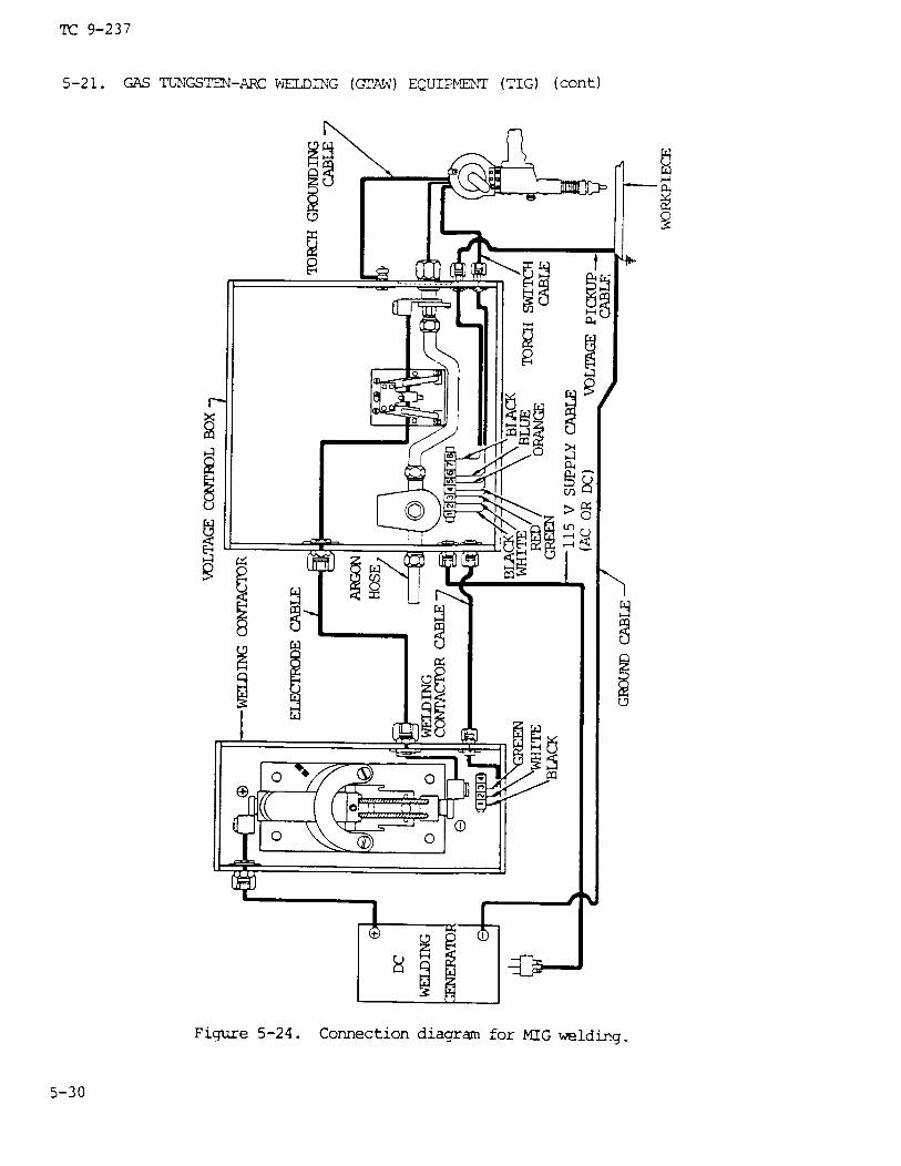
(1) The MIG welding unit is designed for manual welding with small diameterwire electrodes, using a Spool-on-gun torch. The unit consists of a torch (fig.5-23), a voltage control box, and a welding contractor (fig. 5-24). The torchhandle contains a complete motor and gear reduction unit that pulls the weldingwire electrode from a 4 in. (102 mm) diameter spool containing 1 lb (0.5 kg) ofwire electrode mounted in the rear of the torch.
5-29

TC 9-237
(2) Three basic sizes of wire electrode maybe used: 3/32 in. (2.38 mm),3/64 in. (1.19 mm), and 1/16 in. (1.59 mm). Many types of metal may be weldedprovided the welding wire electrode is of the same composition as the base metal.
(3) The unit is designed for use with an ac-dc conventional, constant-currentwelding power supply. Gasoline engine-driven arc welding machines issued to fieldunits may be used as both a power source and a welding source.
c. Nomenclature of Torch.
(1) Contact tube (fig. 5-23). This tube is made of copper and has a hole inthe center of the tube that is from 0.01 to 0.02 in. (0.25 to 0.51 mm) larger thanthe size of the wire electrode being used. The contact tube and the inlet andoutlet guide bushings must be charged when the size of the wire electrode ischanged . The contact tube transfers power from the electrode cable to the weldingwire electrode. An insulated lock screw is provided which secures the contact tubein the torch.
(2) Nozzle and holder (fig. 5-23). The nozzle is made of copper to dissipateheat and is chrome-plated to reflect the heat. The holder is made of stainlesssteel and is connected to an insulating material which prevents an arc from beingdrawn between the nozzle and the ground in case the gun canes in contact with thework.
(3)nylon forelectrode
(4)
Inlet and outlet guide bushings (fig. 5-23). Thelong wear. They must be changed to suit the wirewire is changed.
bushings are made ofelectrode size when the
Pressure roll assembly (fig. 5-23). This is a smooth roller, underspring tension, which pushes the wire electrode against the feed roll and allowsthe wire to be pulled from the spool. A thumbscrew applies tension as required.
(5) Motor (fig. 5-23). When the inch button is depressed, the current forrunning the motor comes from the 110 V ac-dc source, and the rotor pulls the wireelectrode from the spool before starting the welding operation. When the triggeris depressed, the actual welding operation starts and the motor pulls the electrodefrom the spool at the required rate of feed. The current for this rotor is sup-plied by the welding generator.
(6) Spool enclosure assembly (fig. 5-23).which prevents arc spatter from j amming the wirewindow allows the operator to visually check theon the spool.
This assembly is made ofelectrode on the spool.amount of wire electrode
plast icA smallremaining
NOTEIf for any reason the wire electrode stops feeding, a burn-back willresult . With the trigger depressed, the welding contactor is closed,thereby allowing the welding current to flow through the contact tube.AS long as the wire electrode advances through the tube, an arc will bedrawn at the end of the wire electrode. Should the wire electrode stopfeeding while the trigger is still being depressed, the arc will thenform at the end of the contact tube, causing it to melt off. This iscalled burn-back.
5-31

TC 9-237
5-21. GAS TUNGSTEN-ARC WELDING (GTAW) EQUIPMENT (TIG) (cent)
(7) Welding contactor (fig. 5-24). The positive cable from the dc weldinggenerator is connected to a cable coming out of the welding contactor, and theground cable is connected to the workpiece. The electrode cable and the weldingcontactor cable are connected between the welding contactor and voltage control boxas shown.
(8) Argon gas hose (fig. 5-24). This hose is connected from the voltagecontrol box to the argon gas regulator on the argon cylinder.
(9) Electrode cable (fig. 5-24). The electrode cable enters through thewelding current relay and connects into the argon supply line. Both then go out ofthe voltage control box and into the torch in one line.
(10 ) Voltage pickup cable (fig. 5-24). This cable must be attached to theground cable at the workpiece. This supplies the current to the motor during weld-ing when the trigger is depressed.
(11 ) Torch switch and grounding cables ( fig. 5-24). The torch switch cable isconnected into the voltage control box, and the torch grounding cable is connectedto the case of the voltage control box.
5-23. OPERATING THE MIG
a. Starting to Weld.
(1) Press the inchnozzle until 1/2 in. (13line switch “ON” and thetor may begin to weld.
button and allow enough wire electrode to emerge from themm) protrudes beyond the end of the nozzle. With the mainargon gas and power sources adjusted properly, the opera-
(2) When welding in the open air, a protective shield must be installed toprevent the argon gas from being blown away from the weld zone and allowing theweld to become contaminate.
(3) Press the torch trigger. This sends current down the torch switch cableand through the contactor cable, closing the contactor.
(4) When the contactor closes, the welding circuit from the generator to thewelding torch is completed.
(5) At the same time the contactor closes, the argon gas solenoid valveopens, allowing a flow of argon gas to pass out of the nozzle to shield the weldzone.
(6) Lower the welding helmet and touch the end of the wireworkpiece. The gun is held at a 90 degree angle to the work butdegree angle toward the line of travel.
electrode to thepointed at a 10
CAUTIONTo prevent overloading the torch motor when stopping the arc, releasethe trigger; never snap the arc out by raising the torch without firstreleasing the trigger.
5-32

TC 9-237
(7) Welding will continue as long as the arc is maintained and the trigger isdepressed.
b. Setting the Wire Electrode Feed.
(1) A dial on the front of the voltage control box, labeled WELDING CONTROL,is used to regulate the speed of the wire electrode feed.
(2) To increase the speed of the wire electrode being fed from the spool.
arcthefed
100and
turn the dial counterclockwise. This decreases the amount of resistance across theand allows the motor to turn faster. Turning the dial clockwise will increaseamount of resistance, thereby decreasing the speed of the wire electrode beingfrom the spool.
(3) At the instant that the wire electrode touches the work, between 50 andvolts dc is generated. This voltage is picked up by the voltage pickup cableshunted back through the voltage control box into a resistor. There it is
reduced to the correct voltage (24 V dc) and sent to the torch motor.
c. Fuses.
(1) Two 10-ampere fuses, located at the front of the voltage control box,protect and control the electrical circuit within the voltage control box.
(2) A l-ampere fuse, located on the front of the voltage control box, pro-tects and controls the torch motor.
d. Installing the Wire Electrode.
(1)bly (fig.
(2)
Open the spool enclosure cover assembly, brake, and pressure roll assem-5-23) .
the spool.
(3) Feed this straightened end oflet bushings; then place spool onto the
(4) Close the Pressure roller and
Unroll and straighten 6 in. (152 mm) of wire electrode from the top of
the wire electrode into the inlet and out-mounting shaft.
secure it in place. Press the inch button.feeding the wire electrode until there is 1/2 in. (13 mm) protruding beyond the end.to the nozzle.
e. Setting the Argon Gas Pressure.
(1) Flip the argon switchMANUAL position.
(2) Turn on the argon gastor.
on the front of the voltage control
cylinder valve and set the pressure
panel to the
on the regula-
(3) When the proper pressure is set on the regulator, flip the argon switchto the AUTOMATIC POSITION.
5-33

TC 9-237
5-23. OPERATING THE MIG TORCH (cont)
(4) When in the MANUAL position, the argon gas continues to flow. When inthe AUTOMATIC position, the argon gas flows only when the torch trigger is de-pressed, and stops flowing when the torch trigger is released.
f . Generator Polarity. The generator is set on reverse polarity. When set onstraight polarity, the torch motor will run in reverse, withdrawing the wire elec-trode and causing a severe burn-back.
g. Reclaiming Burned-Back Contact Tubes. When the contact tubes are new, theyare 5-3/8 in. (137 mm) long. When burn-backs occur, a maximum of 3/8 in. (9.5 mm)may be filed off. File a flat spot on top of the guide tube, place a drill piloton the contact tube, then drill out the contact tube. For a 3/64 in. (1.2 mm)contact tube, use a No. 46 or 47 drill bit.
h. Preventive Maintenance.
(1) Keep all weld spatter cleaned out of the inside of the torch. Welding inthe vertical or overhead positions will cause spatter to fall down inside the torchnozzle holder and restrict the passage of the argon gas. Keep all hose connectionstight .
(2) To replace the feed roll, remove the nameplate on top of the torch, theflathead screw and retainer from the feed roll mounting shaft, and the contact ringand feed roll. Place a new feed roll on the feed roll mounting shaft, making cer-tain that the pins protruding from the shaft engage the slots in the feed roll.Reassemble the contact ring and nameplate.
5-24. OTHER WELDING EQUIPMENT
a. Cables. Two welding cables of sufficient current carrying capacity withheavy, tough, resilient rubber jackets are required. One of the cables should becomposed of fine copper strands to permit as much flexibility as the size of thecable will allow. One end of the less flexible cable is attached to the ground lugor positive side of the direct current welding machine; the other end to the worktable or other suitable ground. One end of the flexible cable is attached to theelectrode holder and the other end to the negative side of a direct current weldingmachine for straight polarity. Most machines are equipped with a polarity switchwhich is used to change the polarity without interchanging the welding cables atthe terminals of the machine. For those machines not equipped with polarity switch-es, for reverse polarity, the cables are reversed at the machine.
b. Electrode Holders. An electrode holder is an insulated clamping device forholding the electrode during the welding operation. The design of the holder de-pends on the welding process for which it is used, as explained below.
(1) Metal-arc electrode holder. This is an insulated clamp in which a metalelectrode can be held at any desired angle. The jaws can be opened by means of alever held in place by a spring (fig. 5-25).
5-34

TC 9-237
(2) Atomic hydrogen torch. This electrode holder or torch consists of twotubes in an insulated handle, through which both hydrogen gas and electric currentflow. The hydrogen is supplied to a tube in the rear of the handle from which itis led into the two current carrying tubes by means of a manifold. One of the twoelectrode holders is movable, and the gap between this and the other holder isadjusted by means of a trigger on the handle fig. 5-26).
(3) Carbon-arc electrode holder. This holder is manufactured in three specif-ic types. One type holds two electrodes and is similar in design to the atomichydrogen torch, but has no gas tubes; a secondequipped with a heat shield; the third type iswatercooled.
c. Accessories.
type is a single electrode holderfor high amperage welding and is
(1) Chipping hammer and wire brush. A chipping hammer is required to loosenscale, oxides and slag. A wire brush is used to clean each weld bead before fur-ther welding. Figure 5-27 shows a chipping hammer with an attachable wire brush.
5-35

TC 9-237
5-24. OTHER WELDING EQUIPMENT (cont)
(2) Welding table. A welding table should be of all-steel construction. Acontainer for electrodes with an insulated hook to hold the electrode holder whennot in use should be provided. A typical design for a welding table is shown infigure 5-28.
(3) Clamps and backup bars. Workpieces for welding should be clamped inposition with C-clamps or other clamp brackets. Blocks, strips, or bars of copperor cast iron should be available for use as backup bars in welding light sheetaluminum and in making certain types of joints. Carbon blocks, fire clay, or otherfire-resistant material should also be available. These materials are used to formmolds which hold molten metal within given limits when building up sections. Amixture of water, glass, and fire clay or carbon powder can be used for makingmolds .
d. Goggles. Goggles with green lenses shaped to cover the eye orbit should beavailable to provide glare protection for personnel in and around the vicinity ofwelding and cutting operations (other than the welder).
NOTEThese goggles should not be used in actual welding operations.
5-36

TC 9-237
5-25. ELECTRODES AND THEIR USE
a. General. When molten metal is exposed to air, it absorbs oxygen and nitro-gen, and becomes brittle or is otherwise adversely affected. A slag cover is need-ed to protect molten or solidifying weld metal from the atmosphere. This cover canbe obtained from the electrode coating, which protects the metal from damage, stabi-lizes the arc, and improves the weld in the ways described below.
b. Types of Electrodes. The metal-arc electrodes may be grouped and classifiedas bare electrodes, light coated electrodes, and shielding arc or heavy coatedelectrodes. The type used depends on the specific properties required in the welddeposited. These include corrosion resistance, ductility, high tensile strength,the type of base metal to be welded; the position of the weld (i.e., flat, horizon-tal, vertical, or overhead); and the type of current and polarity required.
c. Classification of Electrodes. The American Welding Society’s classificationnumber series has been adopted by the welding industry. The electrode identifica-tion system for steel arc welding is set up as follows:
(1) E indicates electrode for arc welding.
(2) The first two (or three) digits indicate tensile strength (the resistanceof the material to forces trying to pull it apart) in thousands of pounds persquare inch of the deposited metal.
(3) The third (or fourth) digit indicates the position of the weld. 0 indi-cates the classification is not used; 1 is for all positions; 2 is for flat andhorizontal positions only; 3 is for flat position only.
(4) The fourth (or fifth) digit indicates the type of electrode coating andthe type of power supply used; alternating or direct current, straight or reversepolarity.
(5) The types of coating, welding current, and polarity position designatedby the fourth (or fifth) identifying digit of the electrode classification are aslisted in table 5-4.
(6) The number E601O indicates an arc welding electrode withrelieved tensile strength of 60,000 psi; is used in all positions;polarity direct current is required.
a minimum stressand reverse
5-37

TC 9-237
5-25. ELECTRODES AND THEIR USE (cont)
(3) The eletrode identification system for stainless steel arc welding isset up as follows:
(a) E indicates electrode for arc welding.
(b) The first three digits indicated the American Iron and Steeltype of stainless steel.
(c) The last two digits indicate the current and position used.
(d) The number E-308-16 by this system indicates stainless steel
Insti tute
type 308;used in all positions; with alternating or reverse polarity direct current.
d. Bare Electrodes. Bare electrodes are made of wire compositions required forspecific applications. These electrodes have no coatings other than those requiredin wire drawing. These wire drawing coatings have some slight stabilizing effecton the arc but are otherwise of no consequence. Bare electrodes are used for weld-ing manganese steel and other purposes where a coated electrode is not required oris undesirable. A diagram of the transfer of metal across the arc of a bare elec-trode is shown in figure 5-29.
e. Light Coated Electrodes.
(1) Light coated electrodes have a definite composition. A light coating hasbeen applied on the surface by washing, dipping, brushing, spraying, tumbling, orwiping to improve the stability and characteristics of the arc stream. They arelisted under the E45 series in the electrode identification system.
(2) The coating generally serves the following functions:
(a) It dissolves or reduces impurities such as oxides, sulfur, and phos-phorus.
(b) It changes the surface tension of the molten metal so that the globulesof metal leaving the end of the electrode are smaller and more frequent, making theflow of molten metal more uniform.
(c) It increases the arc stability by introducing materials readily ionized(i.e., changed into small particles with an electric charge) into the arc stream.
5-38

TC 9-237
(3) Some of the light coatings may produce a slag, but it is quite thin anddoes not act in the same manner as the shielded arc electrode type slag. The arcaction obtained with light coated electrodes is shown in figure 5-30.
f . Shielded Arc or Heavy Coated Electrodes. Shielded arc or heavy coated elec-trodes have a definite composition on which a coating has been applied by dippingor extrusion. The electrodes are manufactured in three general types: those withcellulose coatings; those with mineral coatings; and those with coatings of combina-tions of mineral and cellulose. The cellulose coatings are composed of solublecotton or other forms of cellulose with small amounts of potassium, sodium, ortitanium, and in some cases added minerals. The mineral coatings consist of sodiumsilicate, metallic oxides, clay, and other inorganic substances or combinationsthereof. Cellulose coated electrodes protect the molten metal with a gaseous zonearound the arc as well as slag deposit over the weld zone. The mineral coatedelectrode forms a slag deposit only. The shielded arc or heavy coated electrodesare used for welding steels, cast iron, and hard surfacing. The arc action ob-tained with the shielded arc or heavy coated electrode is shown in figure 5-31.
5-39

TC 9-237
5-25. ELECTRODES AND THEIR USE (cont)
g. Functions of Shielded Arc or Heavy Coated Electrodes.
(1) These electrodes produce a reducing gas shield around the arc which pre-vents atmospheric oxygen or nitrogen from contaminating the weld metal. The oxygenwould readily combine with the molten metal, removing alloying elements and causingporosity. The nitrogen would cause brittleness, low ductility, and in some cases,low strength and poor resistance to corrosion.
(2) The electrodes reduce impurities such as oxides, sulfur, and phosphorusso that these impurities will not impair the weld deposit.
(3) They provide substances to the arc which increase its stability and elimi-nate wide fluctuations in the voltage so that the arc can be maintained withoutexcessive spattering.
(4) By reducing the attractive force between the molten metal and the end ofthe electrode, or by reducing the surface tension of the molten metal, the vapor-ized and melted coating causes the molten metal at the end of the electrode tobreak up into fine, small particles.
(5) The coatings contain silicates which will form a slag over the moltenweld and base metal. Since the slag solidifies at a relatively slow rate, it holdsthe heat and allows the underlying metal to cool and slowly solidify. This slowsolidification of the metal eliminates the entrapment of gases within the weld andpermits solid impurities to float to the surface. Slow cooling also has an anneal-ing effect on the weld deposit.
(6) The physical characteristics of the weld deposit are modified by incorp-orating alloying materials in the electrode coating. The fluxing action of the slagwill also produce weld metal of better quality and permit welding at higher speeds.
(7) The coating insulates the sides of the electrode so that the arc is con-centrated into a confined area. This facilitates welding in a deep U or V groove.
(8) The coating produces a cup, cone, or sheath (fig. 5-31) at the tip of theelectrode which acts as a shield, concentrates and directs the arc, reduces heatlosses and increases the temperature at the end of the electrode.
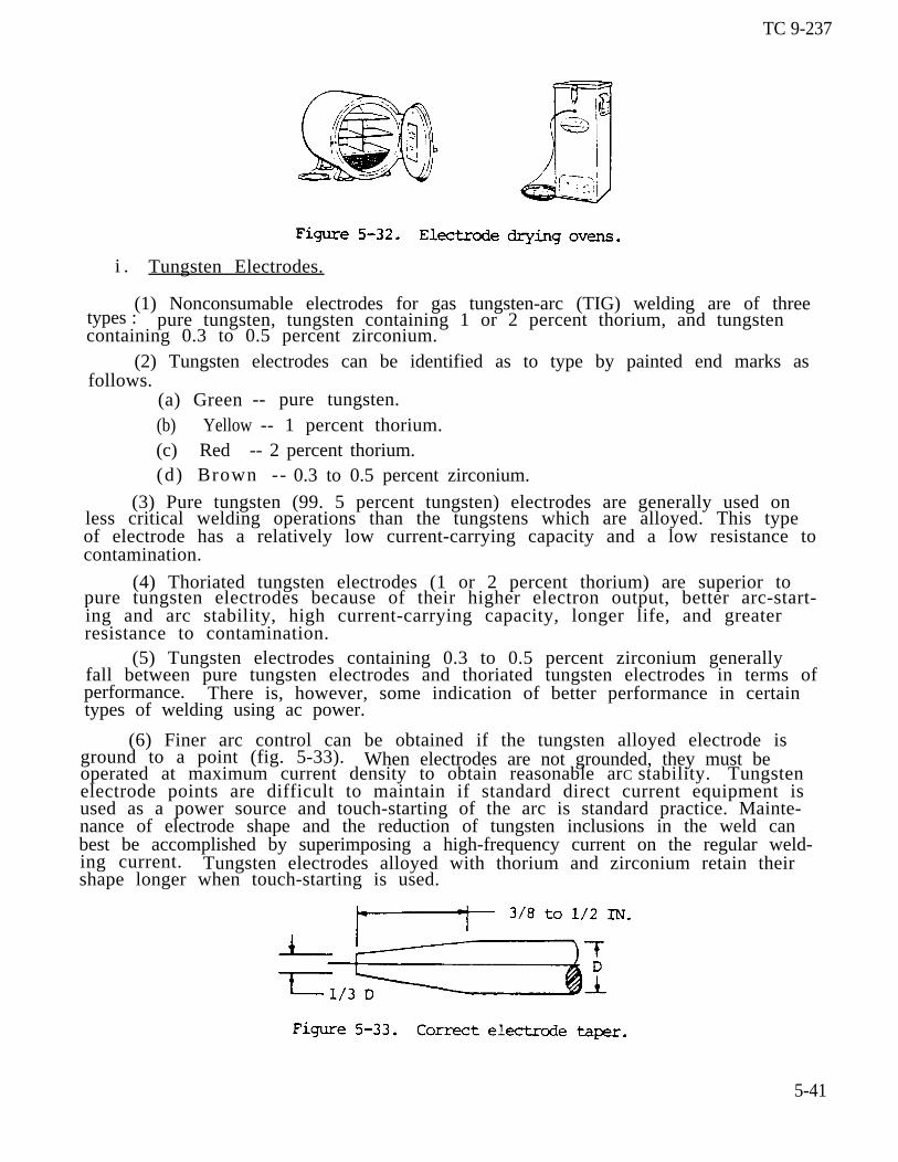
h. Storing Electrodes. Electrodes must be kept dry. Moisture destroys thedesirable characteristics of the coating and may cause excessive spattering andlead to the formation of cracks in the welded area. Electrodes exposed to damp airfor more than two or three hours should be dried by heating in a suitable oven(fig. 5-32) for two hours at 500 0F (260 0C). After they have dried, they shouldbe stored in a moisture proof container. Bending the electrode can cause the coat-ing to break loose from the core wire. Electrodes should not be used if the corewire is exposed.
5-40
TC 9-237
i . Tungsten Electrodes.
(1) Nonconsumable electrodes for gas tungsten-arc (TIG) welding are of threetypes : pure tungsten, tungsten containing 1 or 2 percent thorium, and tungstencontaining 0.3 to 0.5 percent zirconium.
(2) Tungsten electrodes can be identified as to type by painted end marks asfollows.
(a) Green -- pure tungsten.(b) Yellow -- 1 percent thorium.(c) Red -- 2 percent thorium.(d) Brown -- 0.3 to 0.5 percent zirconium.
(3) Pure tungsten (99. 5 percent tungsten) electrodes are generally used onless critical welding operations than the tungstens which are alloyed. This typeof electrode has a relatively low current-carrying capacity and a low resistance tocontamination.
(4) Thoriated tungsten electrodes (1 or 2 percent thorium) are superior topure tungsten electrodes because of their higher electron output, better arc-start-ing and arc stability, high current-carrying capacity, longer life, and greaterresistance to contamination.
(5) Tungsten electrodes containing 0.3 to 0.5 percent zirconium generallyfall between pure tungsten electrodes and thoriated tungsten electrodes in terms ofperformance. There is, however, some indication of better performance in certaintypes of welding using ac power.
(6) Finer arc control can be obtained if the tungsten alloyed electrode isground to a point (fig. 5-33). When electrodes are not grounded, they must beoperated at maximum current density to obtain reasonable arC stability. Tungstenelectrode points are difficult to maintain if standard direct current equipment isused as a power source and touch-starting of the arc is standard practice. Mainte-nance of electrode shape and the reduction of tungsten inclusions in the weld canbest be accomplished by superimposing a high-frequency current on the regular weld-ing current. Tungsten electrodes alloyed with thorium and zirconium retain theirshape longer when touch-starting is used.
5-41

TC 9-237
5-25. ELECTRODES AND THEIR USE (cont)
(7) The electrode extension beyond the gas cup is determined by the type ofjoint being welded. For example, an extension beyond the gas cup of 1/8 in.(3.2 mm) might be used for butt joints in light gage material, while an extensionof approximately 1/4 to 1/2 in. (6.4 to 12.7 mm) might be necessary on some filletwelds. The tungsten electrode of torch should be inclined slightly and the fillermetal added carefully to avoid contact with the tungsten. This will prevent contam-ination of the electrode. If contamination does occur, the electrode must be re-moved, reground, and replaced in the torch.
j . Direct Current Welding. In direct current welding, the welding currentcircuit may be hooked up as either straight polarity (dcsp) or reverse polarity(dcrp). The polarity recommended for use with a specific type of electrode isestablished by the manufacturer.
(1) For dcsp, the welding machine connections are electrode negative andworkpiece positive (fig. 5-34); electron flow is from electrode to workpiece. Fordcrp, the welding machine connections are electrode positive and workpiece nega-tive; electron flow is from workpiece to electrode.
5-42

TC 9-237
(2) For both current polarities, the greatest part of the heating effect oc-curs at the positive side of the arc. The workpiece is dcsp and the electrode isdcrp. Thus, for any given welding current, dcrp requires a larger diameter elec-trode than does dcsp. For example, a l/16-in. (1.6-mm) diameter pure tungstenelectrode can handle 125 amperes of welding current under straight polarity condi-tions. If the polarity were reversed, however, this amount of current would meltoff the electrode and contaminate the weld metal. Hence, a 1/4-in. (6.4-mm) diame-ter pure tungsten electrode is required to handle 125 amperes dcrp satisfactorilyand safely. However, when heavy coated electrodes are used, the composition of thecoating and the gases it produces may alter the heat conditions. This will producegreater heat on the negative side of the arc. One type of coating may provide themost desirable heat balance with straight polarity, while another type of coatingon the same electrode may provide a more desirable heat balance with reverse polari-ty .
(3) The different heating effects influence not only the welding action, butalso the shape of the weld obtained. DCSP welding will produce a wide, relativelyshallow weld (fig. 5-35). DCRP welding, because of the larger electrode diameterand lower currents generally employed, gives a narrow, deep weld.
(4) One other effect of dcrp welding is the so-called plate cleaning effect.This surface cleaning action is caused either by the electrons leaving the plate orby the impact of the gas ions striking the plate, which tends to break up the sur-face oxides, and dirt usually present.
(5) In general, straight polarity is used with all mild steel, bare, or lightcoated electrodes. Reverse polarity is used in the welding of non-ferrous metalssuch as aluminum, bronze, monel, and nickel. Reverse polarity is also used withsane types of electrodes for making vertical and overhead welds.
(6) The proper polarity for a given electrode can be recognized by the sharp,cracking sound of the arc. The wrong polarity will cause the arc to emit a hissingsound, and the welding bead will be difficult to control.
5-43

TC 9-237
5-25. ELECTRODES AND THEIR USE (cont)
k. Alternating Current Welding.
(1) Alternating current welding, theoretically, is a combination of dcsp anddcrp welding. This can be best explained by showing the three current waves visual-ly. As shown in figure 5-36, half of each complete alternating current (ac) cycleis dcsp, the other half is dcrp.
(2) Moisture, oxides, scale, etc., on the surface of the plate tend, partial–ly or completely, to prevent the flow of current in the reverse polarity direc-tion. This is called rectification. For example, in no current at all flowed inthe reverse polarity direction, the current wave would be similar to figure 5-37.
Figure 5-37. Rectified ac wave.
(3) To prevent rectification from occurring, it is common practice to intro-duce into the welding current an additional high-voltage, high-frequency, low-powercurrent. This high-frequency current jumps the gap between the electrode and theworkpiece and pierces the oxide film, thereby forming a path for the welding cur-rent to follow. Superimposing this high-voltage, high-frequency current on thewelding current gives the following advantages:
(a)
(b)
(c)hardfacing
(d)
The arc may be started without touching the electrode to the workpiece.
Better arc stability is obtained.
A longer arc is possible. This is particularly useful in surfacing andoperations.
Welding electrodes have longer life.
The use of wider current range for a specific diameter electrode is (e)poss ib le .
5-44

TC 9-237
(4) A typical weld contour produced with high-frequency stabilized ac isshown in figure 5-38, together with both dcsp and dcrp welds for comparison.
1. Direct Current Arc Welding Electrodes.
(1) The manufacturer’s recommendations should be followed when a specifictype of electrode is being used. In general, direct current shielded arc elec-trodes are designed either for reverse polarity (electrode positive) or forstraight polarity (electrode negative), or both. Many, but not all, of the directcurrent electrodes can be used with alternating current. Direct current is pre-ferred for many types of covered, nonferrous, bare and alloy steel electrodes.Recommendations from the manufacturer also include the type of base metal for whichgiven electrodes are suited, corrections for poor fit-ups, and other specific condi-tions.
(2) In most cases, straight polarity electrodes will provide less penetrationthan reverse polarity electrodes, and for this reason will permit greater weldingspeed. Good penetration can be obtained from either with proper welding condi-tions and arc manipulation.
m. Alternating Current Arc Welding Electrodes.
(1) Coated electrodes which can be used with either direct or alternatingcurrent are available. Alternating current is more desirable while welding in re-stricted areas or when using the high currents required for thick sections becauseit reduces arc blow. Arc blow causes blowholes, slag inclusions, and lack of fu-sion in the weld.
(2) Alternating current is used in atomic hydrogen welding and in those car-bon arc processes that require the use of two carbon electrodes. It permits auniform rate of welding and electrode consumption. In carbon-arc processes whereone carbon electrode is used, direct current straight poarity is recommended,because the electrode will be consumed at a lower rate.
n. Electode Defects and Their Effects.
(1) If certain elements or oxides are present in electrode coatings, the arcstability will be affected. In bare electrodes, the composition and uniformity ofthe wire is an important factor in the control of arc stability. Thin or heavycoatings on the electrodes will riot completely remove the effects of defective wire.
(2) Aluminum or aluminum oxide (even when present in0.01 percent), silicon, silicon dioxide, and iron sulphateunstable. Iron oxide, manganese oxide, calcium oxide, andstabilize the arc.
quantities not exceedingcause the arc to beiron sulphate tend to
5 - 4 5

TC 9-237
5-25. ELECTRODES AND THEIR USE (cont)
(3) When phosphorus or sulfur are present in the electrode in excess of 0.04percent, they will impair the weld metal because they are transferred from the elec-trode to the molten metal with very little loss. Phosphorus causes grain growth,bri t t leness, and “cold shortness” (i.e., brittle when below red heat) in the weld.These defects increase in magnitude as the carbon content of the steel increases.Sulfur acts as a slag, breaks up the soundness of the weld metal, and causes “hotshortness” (i.e., brittle when above red heat). Sulfur is particularly harmful tobare, low-carbon steel electrodes with a low manganese content. Manganese promotesthe formation of sound welds.
(4) If the heat treatment, given the wire core of an electrode, is not uni-form, the electrode will produce welds inferior to those produced with an electrodeof the same composition that has been properly heat treated.
Section IV. RESISTANCE WELDING EQUIPMENT
5-26. RESISTANCE WELDING
a. General. Resistance welding is a group of welding processes in which thejoining of metals is produced by the heat obtained from resistance of the work tothe electric current, in a circuit of which the work is a part, and by the applica-tion of pressure. The three factors involved in making a resistance weld are theamount of current that passes through the work, the pressure that the electrodestransfer to the work, and the time the current flows through the work. Heat isgenerated by the passage of electrical current through a resistance current, withthe maximum heat being generated at the surfaces being joined. Pressure is re-quired throughout the welding cycle to assure a continuous electrical circuitthrough the work. The amount of current employed and the time period are relatedto the heat input required to overcome heat losses and raise the temperature of themetal to the welding temperature. The selection of resistance welding equipment isusually determined by the joint design, construction materials, quality requir-ments, production schedules, and economic considerations. Standard resistancewelding machines are capable of welding a variety of alloys and component sizes.There are seven major resistance welding processes: resistance projection welding,resistance spot welding, resistance flash welding, resistance upset welding, resis-tance seam welding, resistance percussion welding, and resistance high frequencywelding.
b. Principal Elements of Resistance Welding Machines. A resistance weldingmachine has three principal elements:
(1) An electrical circuit with a welding transformer and a current regulator,and a secondary circuit, including the electrodes which conduct the welding currentto the work.
(2) A mechanical system consisting of a machine frame and associated mecha-nisms to hold the work and apply the welding force.
(3) The control equipment (timing devices) to initiate the time and durationof the current flow. This equipment may also control the current magnitude, aswell as the sequence and the time of other parts of the welding cycle.
5-46

TC 9-237
c. Electrical Operation. Resistance welds are made with either semiautomaticor mechanized machines. With the semiautomatic machine, the welding operator posi-tions the work between the electrodes and pushes a switch to initiate the weld; theweld programmer completes the sequence. In a mechanized setup, parts are automati-cally fed into a machine, then welded and ejected without welding operator assis-tance. Resistance welding machines are classified according to their electricaloperation into two basic groups: direct energy and stored energy. Machines inboth groups may be designed to operate on either single-phase or three-phase power.
d. Spot Welding.
(1) There are several types of spot welding machines, including rocker arm,press, portable, and multiple type. A typical spot welding machine, with its essen-tial operating elements for manual operation, is shown in figure 5-39. In thesemachines, the electrode jaws are extended in such a manner as to permit a weld tobe made at a considerable distance f ran the edqe of the base metal sheet. The elec-trodes are composed of a copper alloy and areerable force or squeeze may be applied to the
assembled in a manner by which consid-metal during the welding process.
r
5-47

TC 9-237
5-26. RESISTANCE WELDING (cont)
(a) Rocker arm type. These machines consist essentially of a cylindricalarm or extension of an arm which transmits the electrode force and in most cases,the welding current. They are readily adaptable for spot welding of most weldablemetals. The travel path of the upper electrode is in an arc about the fulcrum ofthe upper arm. The electrodes must be positioned so that both are in the plane ofthe horn axes. Because of the radial motion of the upper electrode, these machinesare not recommended for projection welding.
(b) Press type. In this type of machine, the moveable welding head travelsin a straight line in guide bearings or ways. Press type machines are classifiedaccording to their use and method of force application. They may be designed forspot welding, projection welding, or both. Force may be applied by air or hydrau-lic cylinders, or manually with small bench units.
(c) Portable type. A typical portable spot welding machine consists offour basic units: a portable welding gun or tool; a welding transformer and, insome cases, a rectifier; an electrical contactor and sequence timer; and a cableand hose unit to carry power and cooling water between the transformer and weldinggun. A typical portable welding gun consists of a frame, an air or hydraulic actu-ating cylinder, hand grips, and an initiating switch. The design of the gun istailored to the needs of the assembly to be welded.
(d) Multiple spot welding type. These are special-purpse machines de-signed to weld a specific assembly. They utilize a number of transformers. Forceis applied directly to the electrode through a holder by an air or hydraulic cylin–der. For most applications, the lower electrode is made of a piece of solid copperalloy with one or more electrode alloy inserts that contact the part to be welded.Equalizing guns are often used where standard electrodes are needed on both sidesof the weld to obtain good heat balance, or where variations in parts will not per-mit consistent contact with a large, solid, lower electrode. The same basic weld-ing gun is used for the designs, but it is mounted on a special “C” frame similarto that for a portable spot welding gun. The entire assembly can move as electrodeforce is applied to the weld location.
(2) When spot welding aluminum , conventional spot welding machines used toweld sheet metal may be used. However, the best results are obtained only if cer-tain refinements are incorporated into these machines. These features include thefollowing:
(a) Ability to handle high current for short welding times.
(b) Precise electronic control of current and length of time it is applied.
(c) Rapid follow up of the electrode force by employing anti-friction bear-ings and lightweight, low-inertia heads.
(d) High structural rigidity of the welding machine arms, holders, andplatens in order to minimize deflection under the high electrode forces used foraluminum, and to reduce magnetic deflections, a variable or dual force cycle topermit forging the weld nugget.
5-48

TC 9-237
(e) Slope control to permit a gradual buildup and tapering off of the weld-ing current.
(f) Postheat current to allow slower cooling of the weld.
(g) Good cooling of the Class I electrodes to prevent tip pickup or stick-ing . Refrigerated cooling is often helpful.
e. Projection Welding. The projection welding dies or electrodes have flatsurfaces with larger contacting areas than spot welding electrodes. The effective-ness of this type of welding depends on the uniformity of the projections or emboss-ments on the base metal with which the electrodespress type resistance welding machine is normallyFlat nose or special electrodes are used.
are in contact (fig. 5-40). Theused for projection welding.
f . Seam Welding. A seam welding machine is similar in principle to a spotwelding machine , except that wheel-shaped electrodes are used rather than the elec-trode tips used in spot welding. Several types of machines are used for seam weld-ing, the type used depending on the sevice requirements. In some machines, thework is held in a fixed position and a wheel type electrode is passed over it.Portable seam welding machines use this principle. In the traveling fixture typeseam welding machine, the electrode is stationary and the work is moved. Seamwelding machine controls must provide an on-ff sequencing of weld current and acontrol of wheel rotation. The components of a standard seam welding machine in-clude a main frame that houses the welding transformer and tap switch; a weldinghead consisting of an air cylinder, a ram, and an upper electrode mounting anddrive mechanism; the lower electrode mounting and drive mechanism, if used; thesecondary circuit connections; electronic controls and contactor; and wheel elec-trodes.
g. Upset and Flash Welding. Flash and upset welding machines are similar inconstruct ion. The major difference is the motion of the movable platen duringwelding and the mechanisms used to impart the motion. Flash weld-fig is generallypreferred for joining components of equal cross section end-to-end. Upset weldingis normally used to weld wire, rod, or bar of small cross section and to join theseam continuously in pipe or tubing. Flash welding machines are generally of muchlarger capacity than upset welding machines. However, both of these processes canbe performed on the same type of machine. The metals that are to be joined serveas electrodes.
5-49

TC 9-237
5-26. RESISTANCE WELDING (Cont)
(1) A standard flash welding machine consists of a main frame, stationaryplaten, movable platen , clamping mechanisms and fixtures, a transformer, a tapswitch, electrical controls, and a flashing and upsetting mechanism. Electrodesthat hold the parts and conduct the welding current to them are mounted on theplatens.
(2) Upset welding machines consist of a main frame that houses a transformand tap switch, electrodes to hold the parts and conduct the welding current, andmeans to upset the joint. A primary contactor is used to control the welding cur-rent.
h. Percussion Welding. This process uses heat from an arc produced by a rapiddischarge of electrical energy to join metals. Pressure is applied progressivelyduring or immediately following the electrical discharge. The process is similarto flash and upset welding. Two types of welding machines are used in percussionwelding: magnetic and capacitor discharge. A unit generally consists of a modi-fied press-type resistance welding machine with specially designed transform,controls, and tooling.
i . High Frequency Welding. This process joins metals with the heat generatedfrom the resistance of the work pieces to a high frequency alternating current inthe 10,000 to 500,000 hertz range, and the rapid application of an upsetting forceafter heating is completed. The process is entirely automatic and utilizes equip-ment designed specifically for this process.
Section V. THERMIT WELDING EQUIPMENT
5-27. THERMIT WELDING (TW)
a. General. . Thermit material is a mechanical mixture of metallic aluminum andprocessed iron oxide. Molten steel is produced by the thermit reaction in amagnesite-lined crucible. At the bottom of the crucible, a magnesite stone isburned, into which a magnesite stone thimble is fitted. This thimble provides apassage through which the molten steel is discharged into the mold. The holethrough the thimble is plugged with a tapping pin, which is covered with a fire-resistant washer and refractory sand. The crucible is charged by placing the cor-rect quantity of thoroughly mixed thermit material in it. In preparing the jointfor thermit welding, the parts to be welded must be cleaned, alined, and held firm-ly in place. If necessary, metal is removed from the joint to permit a free flowof the thermit metal into the joint. A wax pattern is then made around the jointin the size and shape of the intended weld. A mold made of refractory sand isbuilt around the wax pattern and joint to hold the molten metal after it ispoured. The sand mold is then heated to melt out the wax and dry the mold. Themold should be properly vented to permit the escape of gases and to allow the prop-er distribution of the thermit metal at the joint. A thermit welding crucible andmold is shown in figure 5-41.
5-50

TC 9-237
5-28. FORGES
Forge welding is ain an air forge orbe either portable
Section VI. FORGE WELDING TOOLS AND EQUIPMENT
form of hot pressure welding which joins metals by heating themother furnace, and then applying pressure. The forge, which mayor stationary, is the most important component of forge welding
equipment. The two types used in hand forge welding are described below..
5-51

TC 9-237
5-28. FORGES (cont)
a. Portable Forge. The essential parts of a forge are a hearth, a tuyere, awater tank, and a blower. One type of portable forge is shown in figure 5-42. Thetuyere is a valve mechanism designed to direct an air blast into the fire. It ismade of cast iron and consists of a fire pot, base with air inlet, blast valve, andash gate. The air blast passes through the base and is admitted to the firethrough the valve. The valve can be set in three different positions to regulatethe size and direction of the blast according to the fire required. The valvehandle is also used to free the valve from ashes. A portable forge may have ahandcrank blower, as shown in figure 5-42, or it may be equipped with an electricblower. The blower produces air blast pressure of about 2 oz per sq in. A hood isprovided on the forge for carrying away smoke and fumes.
b. Stationary Forge. The stationary forge is similar to the portable forgeexcept that it is usually larger with larger air and exhaust connections. Theforge may have an individual blower or there may be a large capacity blower for agroup of forges. The air blast valve usually has three slots at the top, the posi-tions of which can be controlled by turning the valve. The opening of these slotscan be varied to regulate the volume of the blast and the size of the fire. Thestationary forges, like portable forges, are available in both updraft anddowndraft types. In the updraft type, the smoke and gases pass up through the hoodand chimney by natural draft or are drawn off by an exhaust fan. In the downdrafttype, the smoke and fumes are drawn down under an adjustable hood and carriedthrough a duct by an exhaust fan that is entirely separate from the blower. Thedowndraft forge permits better air circulation and shop ventilation, because theremoval of furies and smoke is positive.
5-52

TC 9-237
5-29. FORGING TOOLS
a. Anvil.
(1) The anvil (fig. 5-43) is usually made of two forgings or steel castingswelded together at the waist. The table or cutting block is soft so that cuttersand chisels caning in contact with it will not be dulled. The face is made ofhardened, tempered tool steel which is welded to the top of the anvil. It cannotbe easily damaged by hammering.
(2) The edges of an anvil are rounded for about 4.00 in. (102 mm) back fromthe table to provide edges where stock can be bent without danger of cutting it.All other edges are sharp and will cut stock when it is hammered against them. Thehardy hole is square and is designed to hold the hardy, bottom, swages, fullers,and other special tools. The pritchel hole is round and permits slugs of metal topass through when holes are punched in the stock. The anvil is usually mounted ona heavy block of wood, although steel pedestals or bolsters are sometimes used.The height of the anvil should be adjusted so that the operator’s knuckles willjust touch its face when he stands erect with his arms hanging naturally.
(3) Anvils are designated by weight (i.e., No.in size from No. 100 to No. 300.
b. Other Tools. In addition to the anvil, otheres, tongs, fullers, flatters, chisels, swage blocks,in forging operations.
150 weighs 150 lb), and range
tools such as hammers , sledg-punches, and a vise are used
5-53/ (5-54 blank)
