tb mh-sensor 551217 reve en - mts sensors€¦ · · 2016-06-20meters. highly dynamic ......
TRANSCRIPT

– Smallest magnetostrictive Sensor for Mobile Hydraulics
– Analog output up to 2,500 mm
– Digital output up to 1,500 mm
The Measurable Difference
MH-Series MS Analog/DigitalData Sheet
Temposonics®
Magnetostrictive Linear Position Sensors
NOW WITHDIGITAL OUTPUTAVAILABLE!

I 2 I
Temposonics® MH-Series MS Analog/DigitalData Sheet
1. Product description and technology
Temposonics® sensors can be used in versatile mobile machines without any restriction and replace contact-based linear sensors like potentio-meters. Highly dynamic systems are controlled safely by means of Temposonics® sensors, thus enhancing the productivity, availability and qua-lity of the working process of the machine. Insensitive to vibration, shocks, dust and weathering influence and electro-magnetic disturbances. Temposonics® MH Series sensors are successfully used in front axle and articulated frame steering cylinders, hydraulic jacks and in steering systems for hydraulic units on agricultural and construction machinery.
MagnetostrictionTemposonics® linear sensors are based on the magnetostrictive tech-nology. By measuring the actual position with a non-contact position magnet the sensor operates 100% wear-free. The absolute operating principle enables reliable readings without any reference point or recalibration. A mechanical strain pulse is triggered by the travelling position magnet. The runtime of this ultrasonic wave is measured precisely and compiled into standard electronic output signals.
Simple MechanicsThe extremely robust sensor consists of the following main parts:
The innovative connector system which is easy to install in a few seconds, any soldering or crimping needless, dust-and waterproof up to IP69K.The flange housing with built-in electronics and signal converter.The position magnet as only moving part, which is assembled into the piston bottom. This permanent magnet travels wear-free and contactless along the pressure pipe and measures the actual position.The pressure pipe placed within the drilled piston rod contains the protected magnetostrictive sensing element.
- Due to small dimensions MH sensors require only little space- Suitable for operating pressures up to 350 bar - Unaffected by surrounding media such as ageing or foaming oil- Insensitive to shock and vibration- Designed for all current supply voltages (12/24 VDC)- Temposonics® sensors offer all common used output signals:
• Analog: VDC / mA• Bus protocols: CANopen, SAE J1939
Measurement principle
Magnetic field strain pulse
Mechanichal strain pulse
Strain pulse detector
Moveable position magnet
magnetostrictive sensing element (waveguide)
Magnetic field position magnet
Current interrogation pulse
Temposonics® Connector system (IP69K)
Flange housing Position magnet Pressure pipe1 2 3 4
1
2
3
4

I 3 I
Temposonics® MH-Series MS Analog/DigitalData Sheet
2. Temposonics® connector system M12
MTS presents the innovative connector system for Temposonics® MH-SeriesThe Temposonics® Connector System meets the highest protection requirements important for a harsh environment in mobile hydraulic applications. Protection type IP69K performs water and dust proof. In addition it is even resistive against high pressure water cleaning.
The MH sensor is delivered by MTS together with the new connector system:The connector insert carrier is already connected to the sensor conductors, i.e. no soldering, any colour or connection mistake.
The connector insert is taken out of the cylinder through a borehole. The flange can easily be clicked in position from outside.
Four standard screws must be tightened to mount the connector system on the cylinder. In case of using angled type connectorsthe connector insert can be rotated inside the flange in 45˚ steps.
With a corresponding mating plug the connector system fulfills an IP rating of IP69K.
- Absolutely easy and safe installation.- No brazing or crimping of connecting leads is required.
1 2
3 4
I 4 I
Temposonics® MH-Series MS Analog/DigitalData Sheet
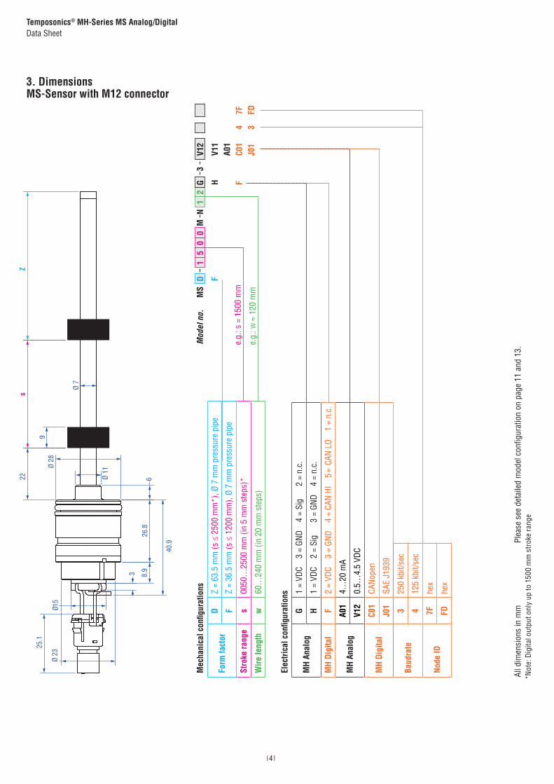
3. DimensionsMS-Sensor with M12 connector
*Not
e: D
igita
l out
put o
nly
up to
150
0 m
m s
trok
e ra
nge
22s
Z
Ø 7
Ø 11
Ø 28
Ø 23
15Ø
9
26.8
8.93
40.9
6
25.1
e.g.
: s =
150
0 m
m
e.g.
: w =
120
mm
All d
imen
sion
s in
mm
Mod
el n
o.
FH F
V11
A01
C01
J01
4 3
MS
D 1
5 0
0 M
N 1
2
G 3
V12
7F FD
Mec
hani
cal c
onfig
urat
ions
Form
fact
orD
Z =
63.5
mm
(s ≤
250
0 m
m*)
, Ø 7
mm
pre
ssur
e pi
pe
FZ
= 36
.5 m
m (s
≤ 1
200
mm
), Ø
7 m
m p
ress
ure
pipe
Stro
ke ra
nge
s00
50…
2500
mm
(in
5 m
m s
teps
)*
Wire
leng
thw
60…
240
mm
(in
20 m
m s
teps
)
Baud
rate
325
0 kb
it/se
c
412
5 kb
it/se
c
Node
ID7F
hex
FDhe
x
Elec
trica
l con
figur
atio
ns
MH
Anal
ogG
1 =
VDC
3 =
GND
4 =
Sig
2
= n.
c.
H1
= VD
C 2
= Si
g 3
= G
ND
4 =
n.c.
MH
Digi
tal
F2
= VD
C 3
= GN
D 4
= CA
N HI
5
= C
AN L
O 1
= n.
c.
MH
Anal
ogA0
14…
20 m
A
V12
0.5…
4.5
VDC
MH
Digi
tal
C01
CANo
pen
J01
SAE
J193
9
Plea
se s
ee d
etai
led
mod
el c
onfig
urat
ion
on p
age
11 a
nd 1
3.

I 5 I
Temposonics® MH-Series MS Analog/DigitalData Sheet
3.1 DimensionsMS-Sensor with cable
*Not
e: D
igita
l out
put o
nly
up to
150
0 m
m s
trok
e ra
nge
Ø 7
s22
9
36.2
6
Ø 11
Ø 23
26.8
Ø 28
46.5
8.4
Z
e.g.
: s =
150
0 m
m
e.g.
: w =
100
0 m
m
All d
imen
sion
s in
mm
Mod
el n
o.
F
MS
D 1
5 0
0 M
T
1 0
A 3
Mec
hani
cal c
onfig
urat
ions
Form
fact
orD
Z =
63.5
mm
(s ≤
250
0 m
m),
Ø 7
mm
pre
ssur
e pi
pe
FZ
= 36
.5 m
m (s
≤ 1
200
mm
), Ø
7 m
m p
ress
ure
pipe
Stro
ke ra
nge
s00
50…
2500
mm
(in
5 m
m s
teps
)*
Wire
leng
thw
300…
9000
mm
(in
100
mm
ste
ps)
Plea
se s
ee d
etai
led
mod
el c
onfig
urat
ion
on p
age
11 a
nd 1
3.
Elec
trica
l con
figur
atio
ns
MS
Anal
ogA
BN =
VDC
W
H =
GND
GN =
Sig
MS
Digi
tal
BN =
VDC
W
H =
GND
GN =
CAN
LO
YE =
CAN
HI
MS
Anal
ogA0
14…
20 m
A
V12
0.5…
4.5
VDC
MS
Digi
tal
C01
CANo
pen
J01
SAE
J193
9
Baud
rate
250
0 kb
it/se
c
412
5 kb
it/se
c
Node
ID7F
hex
FDhe
x
V11
A01
C01
J01
V12
2 47F FD

I 6 I
Temposonics® MH-Series MS Analog/DigitalData Sheet
Sensor installationThe method of installation is entirely dependent on the cylinder design. While the most common method of installation is from the rod side of the cylinder, an installation from the head side of the cylinder is also possible. In both installation methods, the hermetic sealing of the cylinder is given by an O-ring with additional back up ring.
4. In Cylinder assembly
Mechanical installationThe robust Temposonics® model MH sensor is designed for direct stroke measurement in hydraulic cylinders. The Temposonics® MH sensor can be installed from the head side or the rod side of the cylinder depending on the cylinder design.
All dimensions in mm
Please pay attention to installation manual!
Please pay attention:• The position magnet shall not touch the pressure pipe.• Piston rod drilling: Depth: S + Z + 3 mm Diameter:
Pressure Pipe Ø 7
Drilling Ø 10
• Do not exceed operating pressure.
Type B - Ø Cylinder D - Ø min. H - Depth d - Ø min. h - Depth
MS ≥ 3228H7 screwed28G7 welded
26.8 + 0.2 23.5 < 25
1
4.5
8.5
45°
10.52.5
e.g. retaining with set screw DIN 913 M5 × 10 (with flat point!)max. torque 0.5 Nm
Flange housing with O-ring and back-up ring
M12 connector system
10
2
9
16H8
40
M12
×1
21 17
24
Ø 4,4
10
2
9
16H8
M12 × 1
21
Example
D d
H h
B
22 S Z ≥ 3 mm
> 25
< 23
.5
26.8-0.2

I 7 I
Temposonics® MH-Series MS Analog/DigitalData Sheet
All dimensions in mm
4.1. Position magnets
Please pay attention to installation manual!
*max. mechanical burden, e.g. by circlip, lock washers etc.
Position magnets ( please order separately)
Ø 13.5
Ø 17.4
7.9
Ø 25.4
Ø 13.5 7.9
Ø 32.8 mm(1.29 in.)
Ø 23.8 mm(0.94 in.)
Ø 13.5 mm (0.53 in.)
Ø 4.3 mm(0.17 in.)
7.9 mm(0.31 in.)
Part no. 401 032 400 533 201 542-2
Dimensions
ODM 17.4 mm 25.4 mm 32.8 mm
IDM 13.5 mm 13.5 mm 13.5 mm
Height 7.9 mm 7.9 mm 7.9 mm
Characteristics
Material PA neobond PA ferrite PA ferrite
Weight ca. 5 g ca. 10 g ca. 14 g
Operating temperature −40…+100 °C −40…+100 °C −40…+100 °C
Surface pressure* max. 20 N/mm2 max. 40 N/mm2 max. 40 N/mm2
Fastening torque for M4 screws – – max. 1 Nm
Magnet (M) 401 032 400 533 201 542-2
OD 17.5 mm+0,2 25.5 mm+0,2 32.9 mm+0,2
h - Depth 13.5 mm 13.5 mm 13.5 mm
OD
Ø 10 mm
/ Ø 13 m
m
h
S = ODM × 5 × IDM
SM
Steel POM, PU, Aluminum
WC
Stainless steel(non-magnetic)
4.2. Magnet assembly in piston
Pressure pipe Ø 7
Piston rod drilling (min.) Ø 10

I 8 I
Temposonics® MH-Series MS Analog/DigitalData Sheet
5. Electrical installation
1 2
34
GEN
M
+12/24 VDC
+ −BAT
VDCGNDSignal cable shielding (optional)
Chassis GND
Connecting schematics on vehicle electronics:
1 2
34
GEN
M
+12/24 VDC
+ −BAT
VDCGNDSignal cable shielding (optional)
Chassis GND
Please pay attention to installation manual!
MS AnalogPIN assignment M12 (4 pin)
1
4 3
2
Pin G H
1 VDC VDC
2 n.c. Signal
3 GND GND
4 Signal n.c.
MS Analog wire assignment
Color Signal
BN VDC
WH GND
GN Signal
Pin assignment “G”
(1) +12/24 VDC(2) n.c.(3) GND (O V)(4) Signal: mA, VDC
0 VDC
Pin assignment “H”
(1) +12/24 VDC(2) Signal: mA, VDC(3) GND (O V)(4) n.c.
0 VDC
MS DigitalPIN assignment M12 (5 pin)
1
4 3
5
2
Pin F
1 n.c.
2 VDC
3 GND
4 CAN HI
5 CAN LO
Pin assignment “F”
(1) n.c.(2) +12/24 VDC(3) GND (O V)(4) CAN HI(5) CAN LO 120 Ω
Bus termination external
MS Digital wire assignment
Color Signal
BN VDC
WH GND
GN CAN LO
YE CAN HI
All dimensions in mm
I 9 I
Temposonics® MH-Series MS Analog/DigitalData Sheet
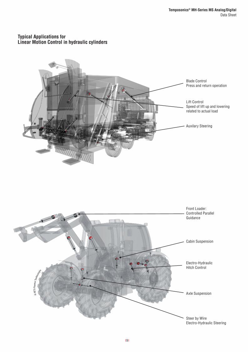
Front Loader:Controlled Parallel Guidance
Blade ControlPress and return operation
Lift ControlSpeed of lift up and lowering related to actual load
Auxilary Steering
Cabin Suspension
Electro-HydraulicHitch Control
Axle Suspension
Steer by WireElectro-Hydraulic Steering
Typical Applications forLinear Motion Control in hydraulic cylinders

I 10 I
Temposonics® MH-Series MS AnalogData Sheet
6.1 MS Analog: Technical data
InputMeasured value PositionStroke range 50…2500 mm (in 5 mm steps)OutputSignal characteristic Analog output restricted by noise or A/D converter of control unitVoltage 0.25…4.75 VDC / 0.5…4.5 VDCCurrent 4…20 mAResolution Typ. 0.1 mmPower up time Typ. 250 msMounting zone 22 mmDamping 36.5 / 63.5 mmAccuracy
Linearity0050…0250 mm ≤ ±0.1 mm,0255…2000 mm ±0.04 % (F.S.), 2005…2500 mm ≤ ±0.8 mm
Repeatability ± 0.1 mmInternal sample rate 2 msSetpoint tolerance ≤ 1 mmOperating conditionsMounting position AnyOperating temperature electronics −40…+105 °CStorage temperature −25…+ 65 °CFluid temperature −30…+ 85 °CDew point, humidity EN60068-2-30, 90 % rel. humidity, no condensationPressureOperating pressure ratings Pressure impulse test according DIN EN ISO 19879Pressure Pipe Ø 7 mmNominal operating pressure (Pn) 300 barMax. overload pressure in cylinder (Pmax) 400 barMax. static proof pressure in cylinder (Pproof) 525 barIP ratingM12 connector EN60529 (IP69K) when pluggedSensor housing EN60529 (IP67)Environmental testingShock test IEC 60068-2-27, 100 g (11 ms) single shock, 50 g (11 ms) at 1000 shocks per axisVibration test IEC 60068-2-64, 15 g (r.m.s.) Ø 7 mm pressure pipe (10…2000 Hz) – resonance frequencies excludedEMC test & evaluation
ISO 14982 Agricultural and forest machinesEN 13309 Construction machinesImmunity: ISO 11452-2 (200 V/m Antenna), ISO 11452-4 (200 mA BCI)Emissions: CISPR 16Transiente Impulses: ISO 7637-2E.S.D.: ISO/TR 10605
Materials and dimensionsPressure pipe Stainless steel 1.4306 / AISI 304LHousing Stainless steel 1.4305 / AISI 303Sealing O-ring 23.47 ×2.62 mm NBR; Backup Ring 28 × 2 × 1.4 mm, Parker Parbaks 8-119 N1444-90 or 8-119 N0300-90M12 connector insert Material: polyamide reinforces; O-ring 7 × 1.35 mm NBR 70; pins: brass with gold plated pinsM12 flange Brass nickel-plated with O-ring 13 × 1.6 NBR 70Electrical installationConnector M12 male plug or cable assemblySupply voltage 12 VDC (8…32 VDC) 24 VDC (8…32 VDC)Current consumption Typ. < 100 mA Typ. < 50 mALoad (output VDC) RL > 10 kΩ RL > 10 kΩLoad current (output VDC) Typ. 0.5 mA Typ. 0.5 mALoud (output mA) RL < 250 Ω RL < 500 ΩInrush current Max. 2.5 A / 2 ms Max. 4.5 A / 2 ms Supply voltage ripple < 1 % p-pPower drain < 1 WOver voltage protection (GND-VDC) Up to +36 VDCPolarity protection (GND-VDC) Up to −36 VDCInsulation Resistance R ≥ 10 MΩ @ 60 secElectric strength 500 VDC (DC GND to chassis GND)

I 11 I
Temposonics® MH-Series MS AnalogData Sheet
Temposonics® Model configurator
b Form factor
D ≤ 2500 mm, Pressure pipe Ø 7 mm, Damping: 63.5 mm
F ≤ 1200 mm, Pressure pipe Ø 7 mm, Damping: 36.5 mm
a Sensor model
M S Flange housing Ø 28 mm
Scope of delivery:Position sensor, O-ring, backup-ring, M12 connector system (optional)
Please order position magnets separately!
c Stroke range (mm)
0050…2500 mm (in 5 mm steps)
d Electrical wiring
M12 connector (VDC – GND – SIG) incl. M12 flange Examples M12 connector
N G 4 pin (1-3-4), 60…240 mm cable length (in 20 mm steps) N08G = 080 mm
N H 4 pin (1-3-2), 60…240 mm cable length (in 20 mm steps) N10H = 100 mm
Cable assembly Example cable length
T A 300…9000 mm cable length (in 100 mm steps) T10A = 1000 mm
e Supply voltage
3 +12 / 24 VDC
f Output
V 1 1 0.25…4.75 VDC
V 1 2 0.5…4.5 VDC
A 0 1 4…20 mA
M S M 3
a b c d e f
I 12 I
Temposonics® MH-Series MS DigitalData Sheet
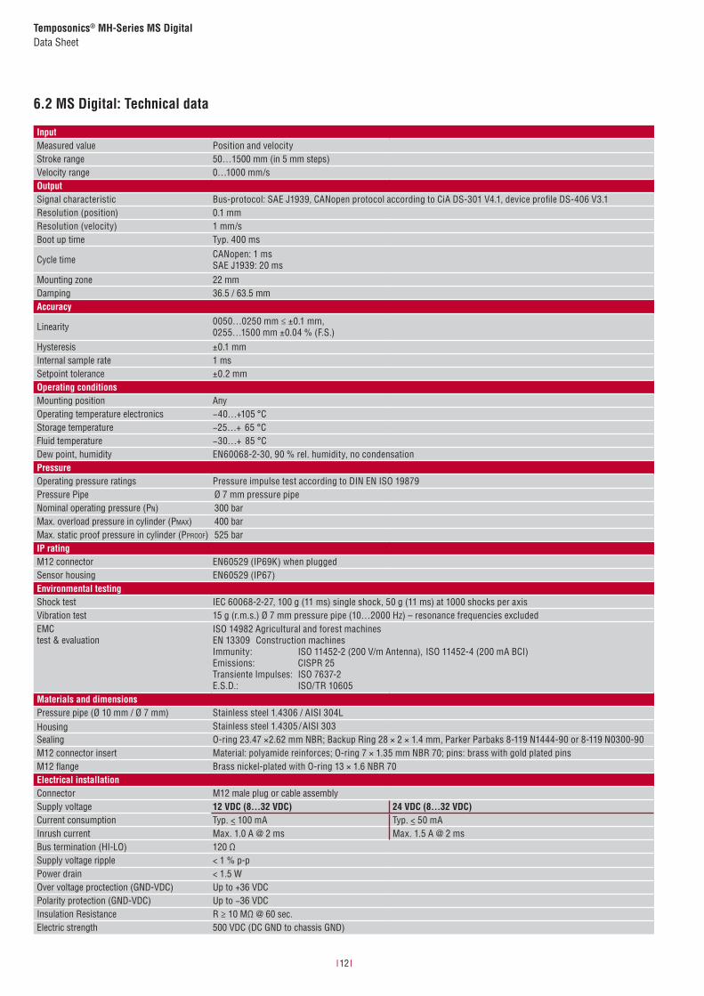
6.2 MS Digital: Technical data
InputMeasured value Position and velocityStroke range 50…1500 mm (in 5 mm steps)Velocity range 0…1000 mm/sOutputSignal characteristic Bus-protocol: SAE J1939, CANopen protocol according to CiA DS-301 V4.1, device profile DS-406 V3.1Resolution (position) 0.1 mmResolution (velocity) 1 mm/sBoot up time Typ. 400 ms
Cycle time CANopen: 1 ms SAE J1939: 20 ms
Mounting zone 22 mmDamping 36.5 / 63.5 mmAccuracy
Linearity 0050…0250 mm ≤ ±0.1 mm,0255…1500 mm ±0.04 % (F.S.)
Hysteresis ±0.1 mmInternal sample rate 1 msSetpoint tolerance ±0.2 mmOperating conditionsMounting position AnyOperating temperature electronics −40…+105 °CStorage temperature −25…+ 65 °CFluid temperature −30…+ 85 °CDew point, humidity EN60068-2-30, 90 % rel. humidity, no condensationPressureOperating pressure ratings Pressure impulse test according to DIN EN ISO 19879Pressure Pipe Ø 7 mm pressure pipeNominal operating pressure (Pn) 300 barMax. overload pressure in cylinder (Pmax) 400 barMax. static proof pressure in cylinder (Pproof) 525 barIP ratingM12 connector EN60529 (IP69K) when pluggedSensor housing EN60529 (IP67) Environmental testingShock test IEC 60068-2-27, 100 g (11 ms) single shock, 50 g (11 ms) at 1000 shocks per axisVibration test 15 g (r.m.s.) Ø 7 mm pressure pipe (10…2000 Hz) – resonance frequencies excludedEMC test & evaluation
ISO 14982 Agricultural and forest machinesEN 13309 Construction machinesImmunity: ISO 11452-2 (200 V/m Antenna), ISO 11452-4 (200 mA BCI)Emissions: CISPR 25Transiente Impulses: ISO 7637-2E.S.D.: ISO/TR 10605
Materials and dimensionsPressure pipe (Ø 10 mm / Ø 7 mm) Stainless steel 1.4306 / AISI 304LHousing Stainless steel 1.4305 / AISI 303Sealing O-ring 23.47 ×2.62 mm NBR; Backup Ring 28 × 2 × 1.4 mm, Parker Parbaks 8-119 N1444-90 or 8-119 N0300-90M12 connector insert Material: polyamide reinforces; O-ring 7 × 1.35 mm NBR 70; pins: brass with gold plated pinsM12 flange Brass nickel-plated with O-ring 13 × 1.6 NBR 70Electrical installationConnector M12 male plug or cable assemblySupply voltage 12 VDC (8…32 VDC) 24 VDC (8…32 VDC)Current consumption Typ. < 100 mA Typ. < 50 mAInrush current Max. 1.0 A @ 2 ms Max. 1.5 A @ 2 msBus termination (HI-LO) 120 ΩSupply voltage ripple < 1 % p-pPower drain < 1.5 WOver voltage proctection (GND-VDC) Up to +36 VDCPolarity protection (GND-VDC) Up to −36 VDCInsulation Resistance R ≥ 10 MΩ @ 60 sec.Electric strength 500 VDC (DC GND to chassis GND)

I 13 I
Temposonics® MH-Series MS DigitalData Sheet
Temposonics® Model configurator
a Sensor model
M S Flange housing Ø 28 mm
c Stroke range (mm)
0050…1500 mm (in 5 mm steps)
e Supply voltage
3 +12/24 VDC
f Output
C 0 1 CANopen cycle time 1 ms (default setting)
J 0 1 SAE J1939 cycle time 20 ms (default setting)
Scope of delivery:Position sensor, O-ring, backup-ring, M12 connector system
Please order position magnets separately!
g Baud rate
CANopen (C01)
0 1000 kbit/s
1 800 kbit/s
2 500 kbit/s
3 250 kbit/s
4 125 kbit/s
6 50 kbit/s
SAE J1939 (J01)
3 250 kBit/s
h Node ID (CANopen) / Source adress (SAE J1939)
CANopen (C01)
hex 01…7F
SAE J1939 (J01)
hex 01…FD
M S M 3
a b c d e f g h
b Form factor
D ≤ 1500 mm, Pressure pipe Ø 7 mm, Damping: 63.5 mm
F ≤ 1200 mm, Pressure pipe Ø 7 mm, Damping: 36.5 mm
d Electrical wiring
M12 connector (VDC – GND – HI – LO) incl. M12 flange Examples M12 connector
N F 5 pin (2-3-4-5), 60…240 mm cable length (in 20 mm steps) N08F = 080 mm
Cable assembly Example cable length
T A 300…9000 mm cable length (in 100 mm steps) T10A = 1000 mm

I 14 I
Temposonics® MH-Series MS DigitalData Sheet
Accessories
Position magnets
OD17.4 Ring magnetPart no. 401 032
OD25.4 Ring magnetPart no. 400 533
OD33 Ring magnetPart no. 201 542-2
Material: PA-NeobindWeight: ca. 5 gOperating temperature: −40…+100 °CSurface pressure: max. 20 N/mm2
Material: PA-FerritWeight: ca. 10 gOperating temperature: −40…+100 °CSurface pressure: max. 40 N/mm2
Material: PA-Ferrit-GF20Weight: ca. 14 gOperating temperature: −40…+100 °CSurface pressure: max. 40 N/mm2
Fastening torque for M4 screw: max. 1 Nm
M12 Flange Testkits
M12 Flange (spare part)Part no. 253 769
Testkit AnalogPart no. 280 618
Testkit DigitalPart no. 254 267
Testsoftware DigitalPart no. 625 129
• MH-Serie analog / PWM Tester• 12 VDC battery charger with
adapter (adapter main plug EU, adapter main plug UK)
• cable with M12 connector• cable with pigtailed wires• carrying case
• USB CAN-Modul Kit: - USB CAN-Modul- USB CAN-Modul Utility CD (driver & manual)
• USB cablecable with MTS M12 connector and RS232 connector
• cable with RS232 connector• carrying case• 12 VDC power supply
Software for MH Digital
Order information:For complete package please
order both part numbers.

Document Part Number: 551217 Revision E (EN) 06/2015
MTS, Temposonics and Level Plus are registered trademarks of MTS Systems Corporationin the United States; MTS SENSORS and the MTS SENSORS logo are trademarks of MTSSystems Corporation within the United States. These trademarks may be protected in othercountries. All other trademarks are the property of their respective owners.Copyright © 2015 MTS Systems Corporation. No license of any intellectual propertyrights is granted. MTS reserves the right to change the information within this document,change product designs, or withdraw products from availability for purchase withoutnotice. Typographic and graphics errors or omissions are unintentional and subject tocorrection. Visit www.mtssensors.com for the latest product information. Product changenotifi cation alerts are available through the MTS Product Change Management System;register at www.mtssensors.com/PCMS.
LOCA
TION
S
LEGA
L NO
TICE
SUSAMTS Systems CorporationSensors Division3001 Sheldon DriveCary, N.C. 27513, USATel. +1- 919 - 677- 0100Fax +1- 919 - 677- [email protected]
JAPANMTS Sensors Technology Corp.737 Aihara-machi, Machida-shi, Tokyo 194-0211, JapanTel. + 81- 42 - 775 - 3838Fax + 81- 42 - 775 - [email protected]
FRANCEMTS Systems SASZone EUROPARC Bâtiment EXA 1616/18, rue Eugène Dupuis94046 Creteil, FranceTel.: + 33 -1 58 43 90 28Fax: + 33 -1 58 43 90 [email protected]
GERMANYMTS Sensor TechnologieGmbH & Co. KGAuf dem Schüffel 958513 Lüdenscheid, GermanyTel. + 49 - 23 51- 95 87 0Fax + 49 - 23 51- 5 64 [email protected]
CHINAMTS Sensors Room 504, Huajing Commercial Center, No. 188, North Qinzhou Road 200233 Shanghai, ChinaTel: + 86 - 21 6485 5800 Fax: + 86 - 21 6495 [email protected]
ITALYMTS Systems Srl.Sensor Division Via Camillo Golgi, 5/725064 Gussago (BS), Italy Tel.: + 39 - 030 988 38 19Fax: + 39 - 030 982 33 [email protected]
Reg.-No. 003095-QN