tastsensor 4 komfort
TRANSCRIPT
Product documentationIssue:20.11.202050013300
Pushbutton sensor 4 KomfortOrder no. 5001 .., 5002 .., 5004 ..
Table of Contents
Pushbutton sensor 4 Komfort | Order no. 5001 .., 5002 .., 5004 .. | 50013300 Page 2 of 106
Table of Contents1 Information on the product ................................................................................................ 4
1.1 Product catalogue.................................................................................................. 41.2 Function ................................................................................................................. 41.3 Device components ............................................................................................... 61.4 Delivery state ......................................................................................................... 71.5 Technical data........................................................................................................ 71.6 Accessories............................................................................................................ 8
2 Safety instructions............................................................................................................. 9
3 Fitting and electrical connection...................................................................................... 10
4 Commissioning................................................................................................................ 12
5 Operation ........................................................................................................................ 13
6 Application programs ...................................................................................................... 15
7 Scope of functions........................................................................................................... 16
8 Channel-oriented device functions.................................................................................. 188.1 Switching.............................................................................................................. 198.2 Dimming............................................................................................................... 208.3 Venetian blind ...................................................................................................... 248.4 Value transmitter.................................................................................................. 298.5 Scene extension .................................................................................................. 328.6 2-channel operation ............................................................................................. 348.7 Controller extension ............................................................................................. 43
8.7.1 Operating mode switchover..................................................................... 438.7.2 Presence function.................................................................................... 448.7.3 Setpoint shift ............................................................................................ 45
8.8 Status LED........................................................................................................... 528.8.1 Basic functions ........................................................................................ 538.8.2 Colour settings......................................................................................... 558.8.3 Brightness settings .................................................................................. 57
9 Channel-independent device functions ........................................................................... 669.1 LED alarm signalling ............................................................................................ 679.2 LED orientation lighting........................................................................................ 719.3 LED night reduction ............................................................................................. 749.4 disabling function ................................................................................................. 779.5 Scene function ..................................................................................................... 899.6 Temperature measurement ................................................................................. 95
Table of Contents
Pushbutton sensor 4 Komfort | Order no. 5001 .., 5002 .., 5004 .. | 50013300 Page 3 of 106
9.7 Room humidity measurement ............................................................................ 1039.8 Transmission delay ............................................................................................ 105
Information on the product | Product catalogue
Pushbutton sensor 4 Komfort | Order no. 5001 .., 5002 .., 5004 .. | 50013300 Page 4 of 106
1 Information on the product
1.1 Product catalogue
Product name Pushbutton sensor 4 Komfort, 1-gang,Pushbutton sensor 4 Komfort, 2-gang,Pushbutton sensor 4 Komfort, 4-gang
Order no. 5001 .., 5002 .., 5004 ..Use SensorDesign FM (flush-mounted)
1.2 FunctionWhen its buttons are actuated, the push-button sensor sends telegrams to the KNX,depending on the ETS parameter settings. These can be telegrams for switching, fordimming or for controlling blinds. It is also possible to program value transmitter func-tions, such as temperature value transmitters or brightness value transmitters. Integ-rated into the push-button sensor is a scene module that can be used to control light-ing and shading systems or various other units as needed by pressing just a singlebutton. The scene function of the push-button sensor supports 8 scenes, allowingcontrol of KNX actuators via 8 scene outputs using switching or value telegrams. It isalso possible to disable all or individual buttons on the device, or to display an alarm.
The push-button sensor can be used as a controller extension, i.e. as an operationand display element of a room temperature controller. As a supplement to the con-troller extension the push-button sensor has an integrated temperature sensor thatmakes it possible to measure and forward the local room temperature. A wiredsensor or a temperature value receive via an object can optionally supplement theroom temperature measurement performed by the internal temperature sensor to im-prove the measurement result. The device offers a second temperature measure-ment via the wired sensor, which is independent from the room temperature meas-urement, if the sensor is not already used for room temperature measurement.
The push-button sensor has an integrated humidity sensor that makes it possible tomeasure and forward the local room humidity.
The push-button sensor consists of up to 8 operating areas, depending on the devicevariant. The operating concept of an operating area can be configured in the ETS asa rocker function or as a button function. With the rocker function, an operating areais divided into two actuation pressure points (left/right) with the same basic function.With the push-button function, an operating area is divided into 2 adjacent, function-ally-separate actuation pressure points (2 buttons).
The push-button sensor has two status LEDs per operating area. These status LEDscan optionally be permanently on or off, or otherwise act as an actuation or status in-dicator for a button or a rocker. As an alternative, the status LEDs can also be activ-ated via separate communication objects. The status LEDs can either indicate theswitching status of an object statically or by flashing, or signal operating states ofroom temperature controllers. The status LEDs can light up in 8 different colours. The
Information on the product | Function
Pushbutton sensor 4 Komfort | Order no. 5001 .., 5002 .., 5004 .. | 50013300 Page 5 of 106
colour of the status LEDs can be configured in the ETS either globally or separately,as required. Optionally a superposed function can be activated via the bus, in whichthe colour and display information of individual status LEDs can be changed accord-ing to priority.
All status LEDs of the push-button sensor can additionally be used as orientationlighting.
Alternatively, communication object control can be used to change the brightness ofall status LEDs. This makes it possible, for example, to reduce the brightness duringnighttime hours to a value configured in the ETS.
The device's programming mode is signalled by status LEDs 1 and 2 flashing simul-taneously. The programming button is located under the topmost rocker. In this man-ner the device can be commissioned even in the installed state. Project design andcommissioning of the device is performed using the ETS from Version 5.6.
If no or a wrong application has been loaded into the push-button sensor with theETS, the status LEDs 1 and 2 flash white to indicate an error. In this case, the push-button sensor will not function.
Information on the product | Device components
Pushbutton sensor 4 Komfort | Order no. 5001 .., 5002 .., 5004 .. | 50013300 Page 6 of 106
1.3 Device components
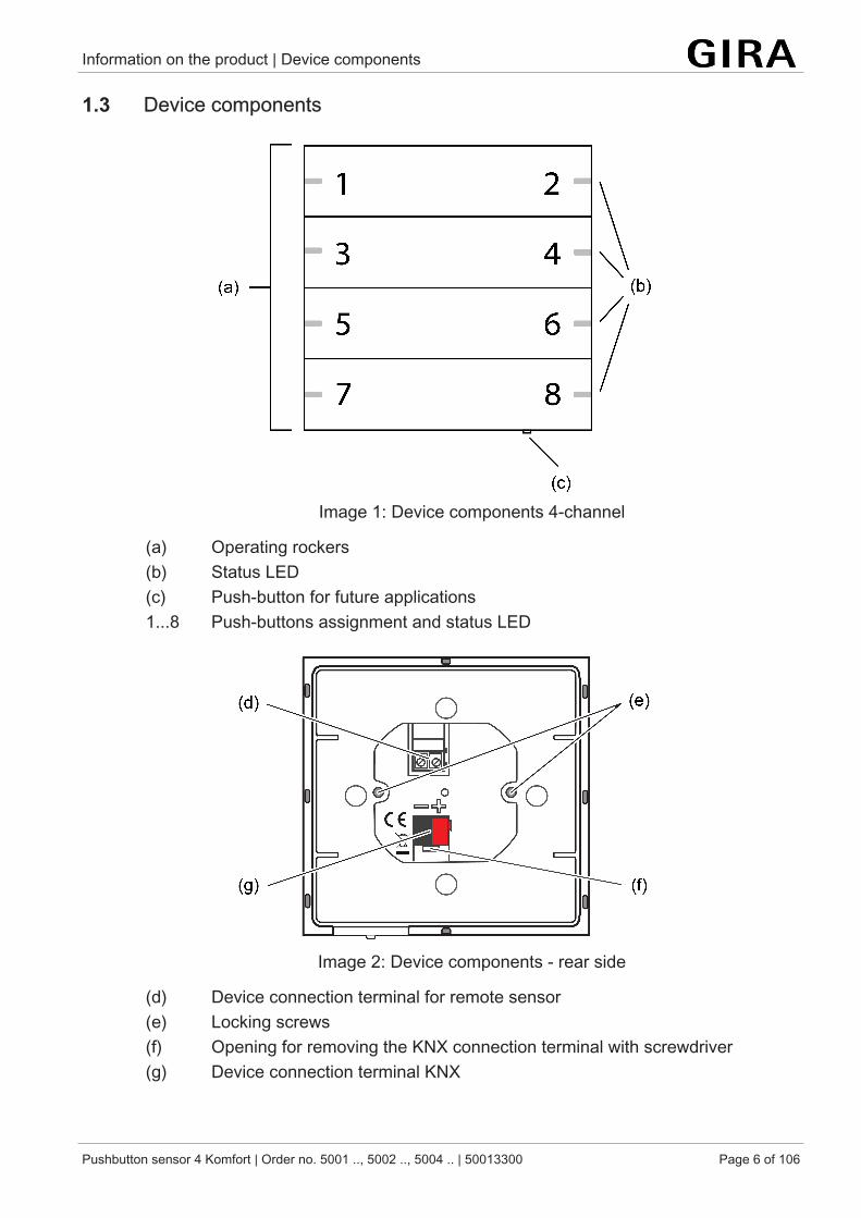
Image 1: Device components 4-channel
(a) Operating rockers(b) Status LED(c) Push-button for future applications1...8 Push-buttons assignment and status LED
Image 2: Device components - rear side
(d) Device connection terminal for remote sensor(e) Locking screws(f) Opening for removing the KNX connection terminal with screwdriver(g) Device connection terminal KNX
Information on the product | Delivery state
Pushbutton sensor 4 Komfort | Order no. 5001 .., 5002 .., 5004 .. | 50013300 Page 7 of 106
1.4 Delivery stateIn the delivery state, the orientation lighting LED is activated. When the bus voltage isconnected, all status LEDs initially light up white. Whenever a button is actuated, therespective illuminated status LED changes colour in the following sequence:
white → red → green → blue → yellow → cyan → orange → violet → white → ...
In the delivery state, the push-button sensor does not send any telegrams to the bus.
1.5 Technical data
KNX
KNX medium TP256Commissioning mode S-modeRated voltage DC 21 ... 32 V SELVCurrent consumption KNX 8 ... 19 mAConnection mode KNX Standard device connection terminalConnecting cable KNX EIB-Y (St)Y 2x2x0.8Protection class III
Mechanism
Loosening torque locking screws Max. 0.8 Nm
Connection cable remote sensor (see accessories)
Cable type extension NYM-J 3×1.5 orJ-Y(St)Y 2×2×0.8
Total length remote sensor line max. 50 m
Ambient conditions
Ambient temperature -5 ... +45 °CStorage/transport temperature -20 ... +70 °C
Information on the product | Accessories
Pushbutton sensor 4 Komfort | Order no. 5001 .., 5002 .., 5004 .. | 50013300 Page 8 of 106
1.6 Accessories
Individually labelled rocker sets are available from the Gira inscription servicewww.beschriftung.gira.de.
Rocker set, 1-gang for pushbutton sensor 4 Order no. 5021 ..Rocker set, 1-gang, inscribable, for pushbutton sensor 4 Order no. 5031 ..
Rocker set, 2-gang for pushbutton sensor 4 Order no. 5022 ..Rocker set, 2-gang, inscribable, for pushbutton sensor 4 Order no. 5032 ..
Rocker set, 4-gang for pushbutton sensor 4 Order no. 5024 ..Rocker set, 4-gang, inscribable, for pushbutton sensor 4 Order no. 5034 ..
Remote sensor Order no. 1493 00
Safety instructions
Pushbutton sensor 4 Komfort | Order no. 5001 .., 5002 .., 5004 .. | 50013300 Page 9 of 106
2 Safety instructionsElectrical devices may only be mounted and connected by electrically skilledpersons.
Serious injuries, fire or property damage possible. Please read and follow manualfully.
Danger of electric shock. During installation and cable routing, comply with the regu-lations and standards which apply for SELV circuits.
Fitting and electrical connection
Pushbutton sensor 4 Komfort | Order no. 5001 .., 5002 .., 5004 .. | 50013300 Page 10 of 106
3 Fitting and electrical connection
DANGER!Mortal danger of electric shock.Cover up live parts in the installation environment.
Mounting and connecting the device
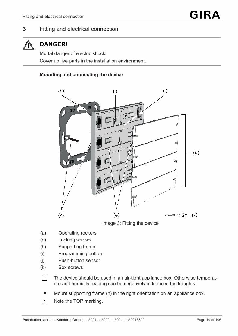
Image 3: Fitting the device
(a) Operating rockers(e) Locking screws(h) Supporting frame(i) Programming button(j) Push-button sensor(k) Box screws
The device should be used in an air-tight appliance box. Otherwise temperat-ure and humidity reading can be negatively influenced by draughts.
■ Mount supporting frame (h) in the right orientation on an appliance box.Note the TOP marking.
Fitting and electrical connection
Pushbutton sensor 4 Komfort | Order no. 5001 .., 5002 .., 5004 .. | 50013300 Page 11 of 106
Use the enclosed box screws (k).
■ Pull off start-up rockers from push-button sensor.The push-button sensor is delivered with start-up rockers. The operating rock-ers suitable for the push-button sensor must be ordered separately (see ac-cessories).
■ Connect push-button sensor (j) to the KNX (g) using KNX connecting terminal(red = +, black = -).
■ Optional: Connect remote sensor (see accessories) to device connection ter-minal (d).
■ Attach push-button sensor (j) onto the supporting frame (h).■ Screw push-button sensor (j) with the integrated locking screws (e) onto sup-
porting frame. Connection torque max. 0.8 Nm.■ Optional: Cover up supporting frame (e) with enclosed label (only for the
device variants 2-gang and 4-gang).Push-button sensor can be put into operation.
Programming the physical address before operating rockers mounting.
■ Snap on operating rockers (a).
Device is ready for operation.
Commissioning
Pushbutton sensor 4 Komfort | Order no. 5001 .., 5002 .., 5004 .. | 50013300 Page 12 of 106
4 Commissioning
Programming the physical address and application program
Project design and commissioning with ETS from 5.6 onwards.
The programming button (i) is located under the topmost operating rocker.
Precondition: The device is connected and ready for operation.The topmost operating rocker is dismantled.
■ Activating Programming mode: push the programming button (i).The status LED 1 and 2 flash red. Programming mode is activated.
■ Programming the physical address.The status LED 1 and 2 return to their previous state. Physical address is pro-grammed.
■ Programming the application program.All status LEDs are switched off while the application program is programmed.As soon as the programming is successfully completed, the status LEDs carryout their parameterised function.
When the application program is discharged and the bus voltage is connected,all status LEDs initially light up white. Whenever a button is actuated, the re-spective illuminated status LED changes colour in (white → red → green → blue→ yellow → cyan → orange → violet → white → ...).
Operation
Pushbutton sensor 4 Komfort | Order no. 5001 .., 5002 .., 5004 .. | 50013300 Page 13 of 106
5 Operation
Operating areas
The push-button sensor consists of up to 4 operating areas, depending on the devicevariant. The operating concept of an operating area can be configured in the ETSeither as a rocker function or alternatively as a button function. With the rocker func-tion, one operating area is divided into two neighbouring actuation pressure pointswith the same basic function. With the button function, an operating area is dividedinto 2 functionally-separate actuation pressure points (2 buttons).
When its buttons are actuated, the push-button sensor sends telegrams to the KNX(switching, dimming, Venetian blind, ...), depending on the ETS parameter settings.
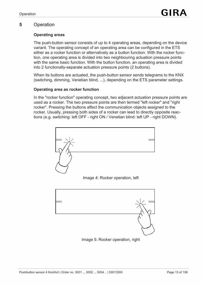
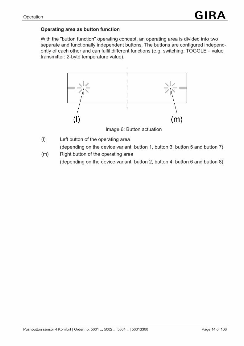
Operating area as rocker function
In the "rocker function" operating concept, two adjacent actuation pressure points areused as a rocker. The two pressure points are then termed "left rocker" and "rightrocker". Pressing the buttons affect the communication objects assigned to therocker. Usually, pressing both sides of a rocker can lead to directly opposite reac-tions (e.g. switching: left OFF - right ON / Venetian blind: left UP - right DOWN).
Image 4: Rocker operation, left
Image 5: Rocker operation, right
Operation
Pushbutton sensor 4 Komfort | Order no. 5001 .., 5002 .., 5004 .. | 50013300 Page 14 of 106
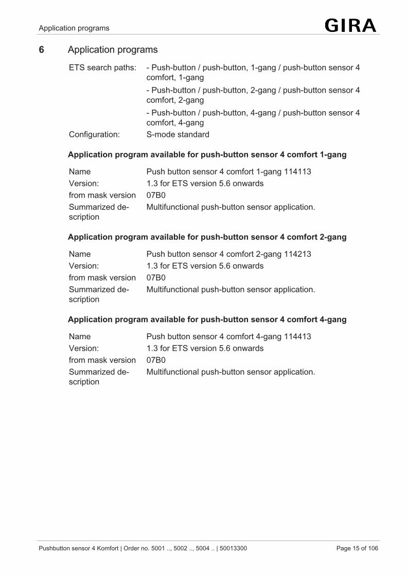
Operating area as button function
With the "button function" operating concept, an operating area is divided into twoseparate and functionally independent buttons. The buttons are configured independ-ently of each other and can fulfil different functions (e.g. switching: TOGGLE – valuetransmitter: 2-byte temperature value).
Image 6: Button actuation
(l) Left button of the operating area(depending on the device variant: button 1, button 3, button 5 and button 7)
(m) Right button of the operating area(depending on the device variant: button 2, button 4, button 6 and button 8)
Application programs
Pushbutton sensor 4 Komfort | Order no. 5001 .., 5002 .., 5004 .. | 50013300 Page 15 of 106
6 Application programs
ETS search paths: - Push-button / push-button, 1-gang / push-button sensor 4comfort, 1-gang- Push-button / push-button, 2-gang / push-button sensor 4comfort, 2-gang- Push-button / push-button, 4-gang / push-button sensor 4comfort, 4-gang
Configuration: S-mode standard
Application program available for push-button sensor 4 comfort 1-gang
Name Push button sensor 4 comfort 1-gang 114113Version: 1.3 for ETS version 5.6 onwardsfrom mask version 07B0Summarized de-scription
Multifunctional push-button sensor application.
Application program available for push-button sensor 4 comfort 2-gang
Name Push button sensor 4 comfort 2-gang 114213Version: 1.3 for ETS version 5.6 onwardsfrom mask version 07B0Summarized de-scription
Multifunctional push-button sensor application.
Application program available for push-button sensor 4 comfort 4-gang
Name Push button sensor 4 comfort 4-gang 114413Version: 1.3 for ETS version 5.6 onwardsfrom mask version 07B0Summarized de-scription
Multifunctional push-button sensor application.
Scope of functions
Pushbutton sensor 4 Komfort | Order no. 5001 .., 5002 .., 5004 .. | 50013300 Page 16 of 106
7 Scope of functions
Functions of the push-button sensor
– Each operating area can either be used as a single rocker or as two independ-ent buttons.
– Each operating area can be used for the functions switching, dimming, Vene-tian blind, value transmitter, scene extension, 2-channel operation and control-ler extension.
– The switching function permits the following settings: reaction after pressingand/or releasing, switch on, switch off, and toggle.
– The dimming function permits the following settings: times for short and longactuation, dimming in different levels, telegram repetition on long press, trans-mission of stop telegram after end of press.
– The shutter control permits the following settings: four different operation con-cepts with times for short and long press and slat adjustment.
– The value transmitter function permits the following settings: selection of thevalue range, value on pressing.
– The scene extension function can be set to scene extension with or withoutstorage function or to internal scene recall with or without storage function.
– 2-channel control: each rocker or each button can be set for controlling two in-dependent channels. This means that only one button-press is enough totransmit up to two telegrams to the bus. The channels can be configured inde-pendently of one another for the switching, value transmitter or recallingscenes functions.
Functions of the controller extension
– The push-button sensor function "controller extension" can be used to activateexternal room temperature controllers.
– Full control of the room temperature controllers (operating mode selection,forced operating mode switch-over, presence function and setpoint shift).
– Evaluation of the controller status via the status LED.
Functions of the status LED
– There is as status LED available for each actuation pressure point.– Each status LED can be configured independently of the operating area.– The status LEDs can light up in red, green, blue, yellow, cyan, orange, violet
or white, according to choice.– Possible status LED functions include "Always OFF", "Always ON", "Button-
press display", "Telegram acknowledgment", "Status display", "Inverted statusdisplay", "Activation via separate LED object", "Operating mode display","Controller status display", "Presence status" and "Inverted presence status".
Scope of functions
Pushbutton sensor 4 Komfort | Order no. 5001 .., 5002 .., 5004 .. | 50013300 Page 17 of 106
– Optionally a superposed function can be activated via the bus, in which thecolour and display information of individual status LEDs can be changed ac-cording to priority.
General functions
– LED alarm signal:All LEDs of the push-button sensor can flash red simultaneously in the eventof an alarm. The following settings are possible: Value of alarm signalling ob-ject for the states alarm and no alarm, alarm acknowledge by actuation of abutton, transmission of the acknowledge signal to other devices.
– LED orientation lighting:All LEDs can be switched permanently off or on for the purpose of orientation,display the status of a separate communication object (ON, OFF, flashing) orbe switched on by pressing any desired button and switched off again auto-matically after a delay time has elapsed.
– LED night reduction:Alternatively, communication object control can be used to change the bright-ness of all status LEDs. This makes it possible, for example, to reduce thebrightness during nighttime hours to a value configured in the ETS.
– Disabling function:The operating areas can be disabled via a 1-bit object. During an active dis-able, all or some of the rockers / buttons can have no function, can performthe function of a selected button or execute one of two presettable disablingfunctions.
– Scene function:Internal storage of up to eight scenes with eight output channels, recall of in-ternal scenes by means of a presettable scene number, selection of objecttypes for the output channels; for each scene, the storage of the individual out-put values and the transmission of the output values can be permitted or inhib-ited; the individual channels can be delayed during scene recall; as scene ex-tension, 64 scenes can be recalled and stored.
– Temperature measurementUp to two temperature measurements possible via internal sensor, wiredsensor, internal and wired sensor, as well as internal and external sensor.
– Room humidity measurementRoom humidity measurement possible via internal sensor.
Channel-oriented device functions |
Pushbutton sensor 4 Komfort | Order no. 5001 .., 5002 .., 5004 .. | 50013300 Page 18 of 106
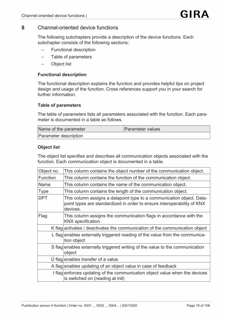
8 Channel-oriented device functionsThe following subchapters provide a description of the device functions. Eachsubchapter consists of the following sections:
– Functional description– Table of parameters– Object list
Functional description
The functional description explains the function and provides helpful tips on projectdesign and usage of the function. Cross references support you in your search forfurther information.
Table of parameters
The table of parameters lists all parameters associated with the function. Each para-meter is documented in a table as follows.
Name of the parameter Parameter valuesParameter description
Object list
The object list specifies and describes all communication objects associated with thefunction. Each communication object is documented in a table.
Object no. This column contains the object number of the communication object.Function This column contains the function of the communication object.Name This column contains the name of the communication object.Type This column contains the length of the communication object.DPT This column assigns a datapoint type to a communication object. Data-
point types are standardized in order to ensure interoperability of KNXdevices.
Flag This column assigns the communication flags in accordance with theKNX specification.
K flag activates / deactivates the communication of the communication objectL flag enables externally triggered reading of the value from the communica-
tion objectS flag enables externally triggered writing of the value to the communication
objectÜ flag enables transfer of a valueA flag enables updating of an object value in case of feedbackI flag enforces updating of the communication object value when the devices
is switched on (reading at init)
Channel-oriented device functions | Switching
Pushbutton sensor 4 Komfort | Order no. 5001 .., 5002 .., 5004 .. | 50013300 Page 19 of 106
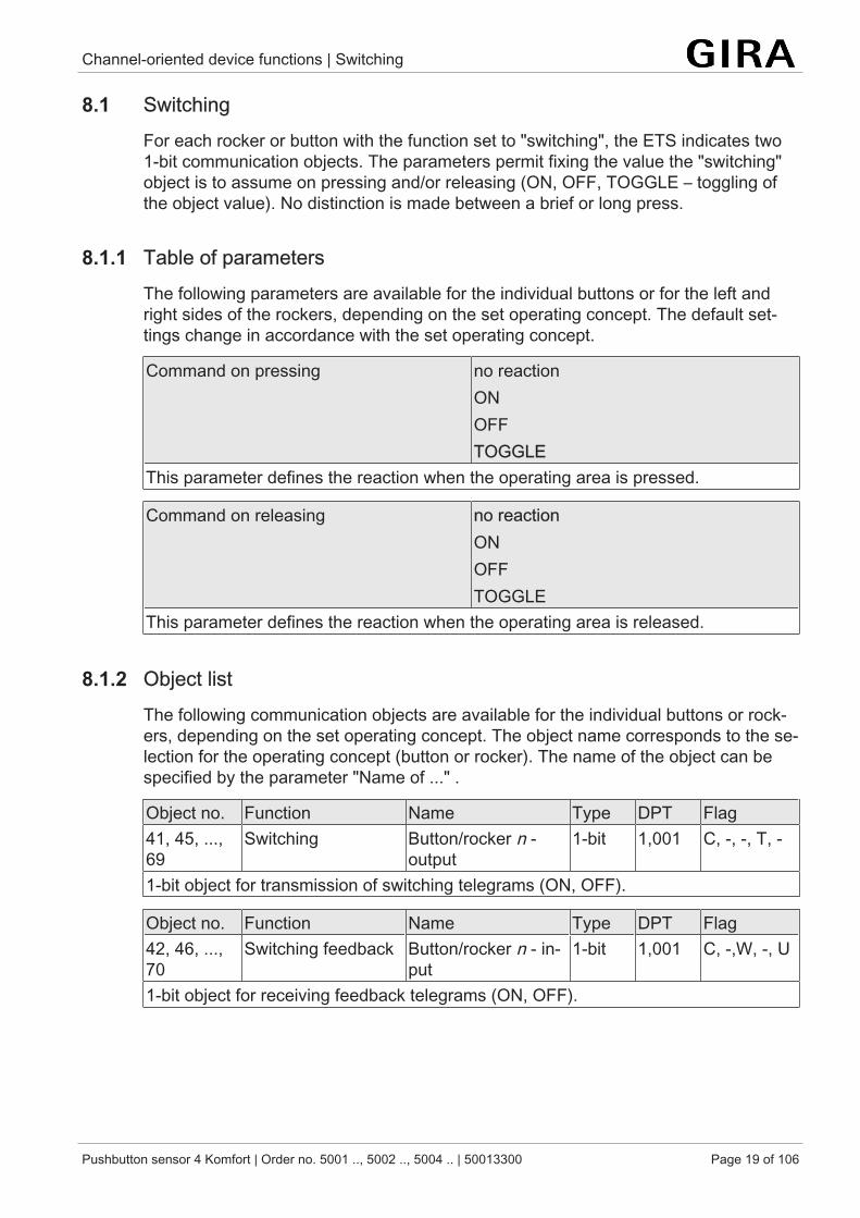
8.1 SwitchingFor each rocker or button with the function set to "switching", the ETS indicates two1-bit communication objects. The parameters permit fixing the value the "switching"object is to assume on pressing and/or releasing (ON, OFF, TOGGLE – toggling ofthe object value). No distinction is made between a brief or long press.
8.1.1 Table of parametersThe following parameters are available for the individual buttons or for the left andright sides of the rockers, depending on the set operating concept. The default set-tings change in accordance with the set operating concept.
Command on pressing no reactionONOFFTOGGLE
This parameter defines the reaction when the operating area is pressed.
Command on releasing no reactionONOFFTOGGLE
This parameter defines the reaction when the operating area is released.
8.1.2 Object listThe following communication objects are available for the individual buttons or rock-ers, depending on the set operating concept. The object name corresponds to the se-lection for the operating concept (button or rocker). The name of the object can bespecified by the parameter "Name of ..." .
Object no. Function Name Type DPT Flag41, 45, ...,69
Switching Button/rocker n -output
1-bit 1,001 C, -, -, T, -
1-bit object for transmission of switching telegrams (ON, OFF).
Object no. Function Name Type DPT Flag42, 46, ...,70
Switching feedback Button/rocker n - in-put
1-bit 1,001 C, -,W, -, U
1-bit object for receiving feedback telegrams (ON, OFF).
Channel-oriented device functions | Dimming
Pushbutton sensor 4 Komfort | Order no. 5001 .., 5002 .., 5004 .. | 50013300 Page 20 of 106
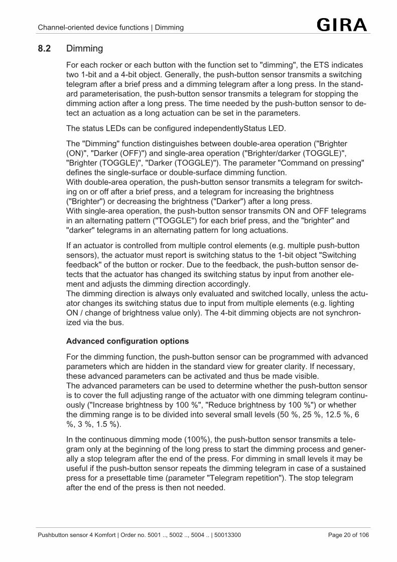
8.2 DimmingFor each rocker or each button with the function set to "dimming", the ETS indicatestwo 1-bit and a 4-bit object. Generally, the push-button sensor transmits a switchingtelegram after a brief press and a dimming telegram after a long press. In the stand-ard parameterisation, the push-button sensor transmits a telegram for stopping thedimming action after a long press. The time needed by the push-button sensor to de-tect an actuation as a long actuation can be set in the parameters.
The status LEDs can be configured independentlyStatus LED.
The "Dimming" function distinguishes between double-area operation ("Brighter(ON)", "Darker (OFF)") and single-area operation ("Brighter/darker (TOGGLE)","Brighter (TOGGLE)", "Darker (TOGGLE)"). The parameter "Command on pressing"defines the single-surface or double-surface dimming function.With double-area operation, the push-button sensor transmits a telegram for switch-ing on or off after a brief press, and a telegram for increasing the brightness("Brighter") or decreasing the brightness ("Darker") after a long press.With single-area operation, the push-button sensor transmits ON and OFF telegramsin an alternating pattern ("TOGGLE") for each brief press, and the "brighter" and"darker" telegrams in an alternating pattern for long actuations.
If an actuator is controlled from multiple control elements (e.g. multiple push-buttonsensors), the actuator must report is switching status to the 1-bit object "Switchingfeedback" of the button or rocker. Due to the feedback, the push-button sensor de-tects that the actuator has changed its switching status by input from another ele-ment and adjusts the dimming direction accordingly.The dimming direction is always only evaluated and switched locally, unless the actu-ator changes its switching status due to input from multiple elements (e.g. lightingON / change of brightness value only). The 4-bit dimming objects are not synchron-ized via the bus.
Advanced configuration options
For the dimming function, the push-button sensor can be programmed with advancedparameters which are hidden in the standard view for greater clarity. If necessary,these advanced parameters can be activated and thus be made visible.The advanced parameters can be used to determine whether the push-button sensoris to cover the full adjusting range of the actuator with one dimming telegram continu-ously ("Increase brightness by 100 %", "Reduce brightness by 100 %") or whetherthe dimming range is to be divided into several small levels (50 %, 25 %, 12.5 %, 6%, 3 %, 1.5 %).
In the continuous dimming mode (100%), the push-button sensor transmits a tele-gram only at the beginning of the long press to start the dimming process and gener-ally a stop telegram after the end of the press. For dimming in small levels it may beuseful if the push-button sensor repeats the dimming telegram in case of a sustainedpress for a presettable time (parameter "Telegram repetition"). The stop telegramafter the end of the press is then not needed.
Channel-oriented device functions | Dimming
Pushbutton sensor 4 Komfort | Order no. 5001 .., 5002 .., 5004 .. | 50013300 Page 21 of 106
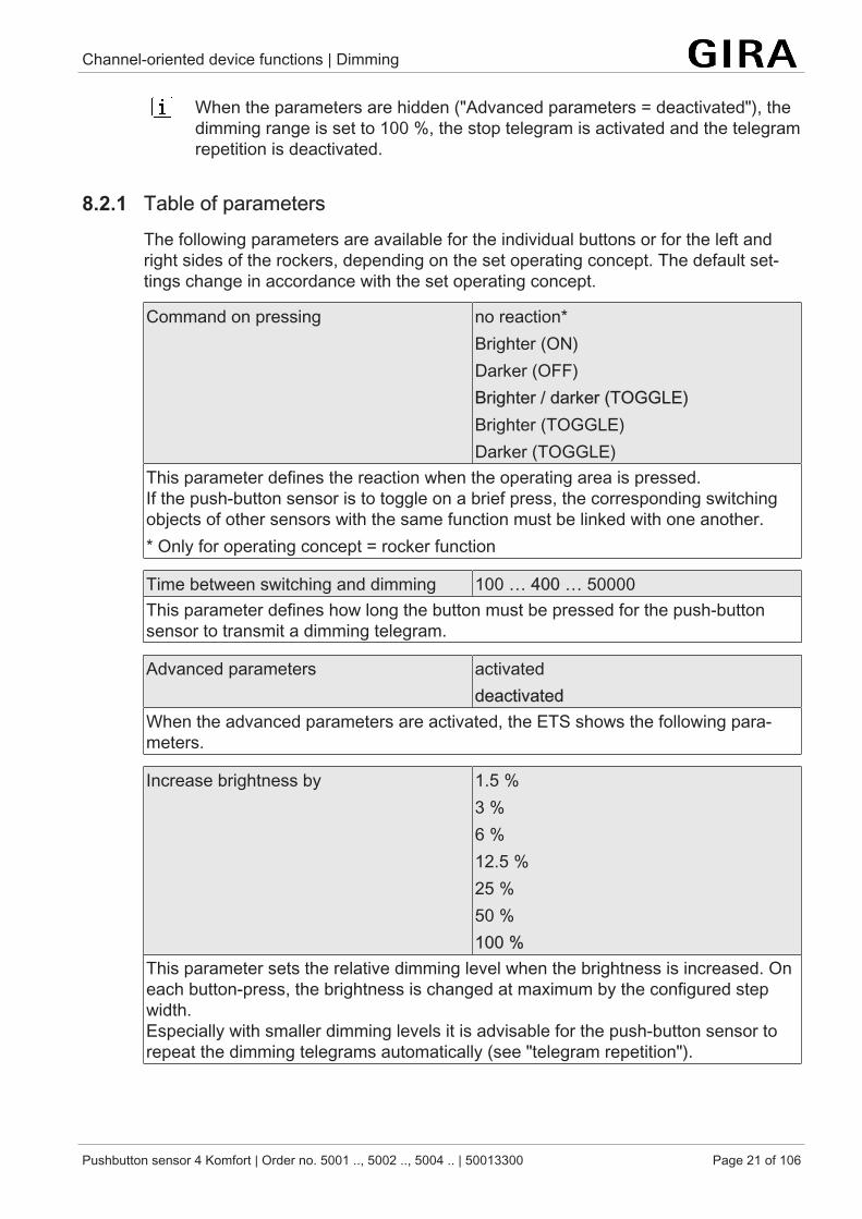
When the parameters are hidden ("Advanced parameters = deactivated"), thedimming range is set to 100 %, the stop telegram is activated and the telegramrepetition is deactivated.
8.2.1 Table of parametersThe following parameters are available for the individual buttons or for the left andright sides of the rockers, depending on the set operating concept. The default set-tings change in accordance with the set operating concept.
Command on pressing no reaction*Brighter (ON)Darker (OFF)Brighter / darker (TOGGLE)Brighter (TOGGLE)Darker (TOGGLE)
This parameter defines the reaction when the operating area is pressed.If the push-button sensor is to toggle on a brief press, the corresponding switchingobjects of other sensors with the same function must be linked with one another.* Only for operating concept = rocker function
Time between switching and dimming 100 … 400 … 50000This parameter defines how long the button must be pressed for the push-buttonsensor to transmit a dimming telegram.
Advanced parameters activateddeactivated
When the advanced parameters are activated, the ETS shows the following para-meters.
Increase brightness by 1.5 %3 %6 %12.5 %25 %50 %100 %
This parameter sets the relative dimming level when the brightness is increased. Oneach button-press, the brightness is changed at maximum by the configured stepwidth.Especially with smaller dimming levels it is advisable for the push-button sensor torepeat the dimming telegrams automatically (see "telegram repetition").
Channel-oriented device functions | Dimming
Pushbutton sensor 4 Komfort | Order no. 5001 .., 5002 .., 5004 .. | 50013300 Page 22 of 106
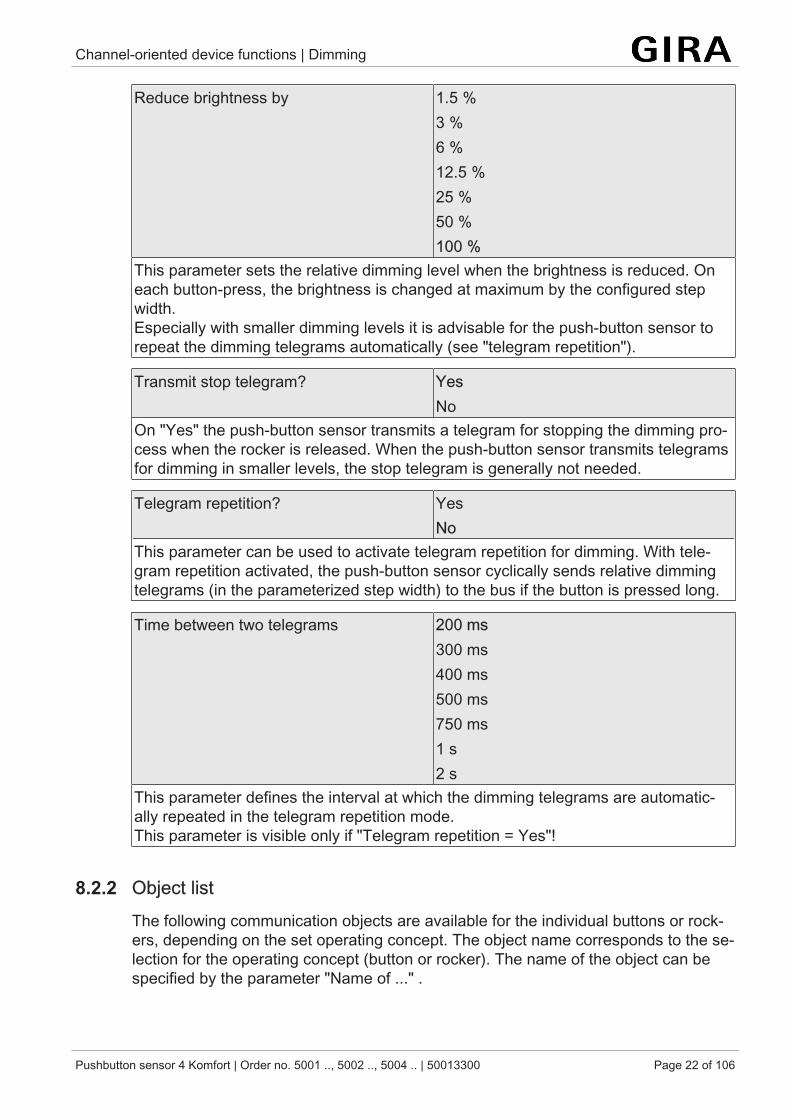
Reduce brightness by 1.5 %3 %6 %12.5 %25 %50 %100 %
This parameter sets the relative dimming level when the brightness is reduced. Oneach button-press, the brightness is changed at maximum by the configured stepwidth.Especially with smaller dimming levels it is advisable for the push-button sensor torepeat the dimming telegrams automatically (see "telegram repetition").
Transmit stop telegram? YesNo
On "Yes" the push-button sensor transmits a telegram for stopping the dimming pro-cess when the rocker is released. When the push-button sensor transmits telegramsfor dimming in smaller levels, the stop telegram is generally not needed.
Telegram repetition? YesNo
This parameter can be used to activate telegram repetition for dimming. With tele-gram repetition activated, the push-button sensor cyclically sends relative dimmingtelegrams (in the parameterized step width) to the bus if the button is pressed long.
Time between two telegrams 200 ms300 ms400 ms500 ms750 ms1 s2 s
This parameter defines the interval at which the dimming telegrams are automatic-ally repeated in the telegram repetition mode.This parameter is visible only if "Telegram repetition = Yes"!
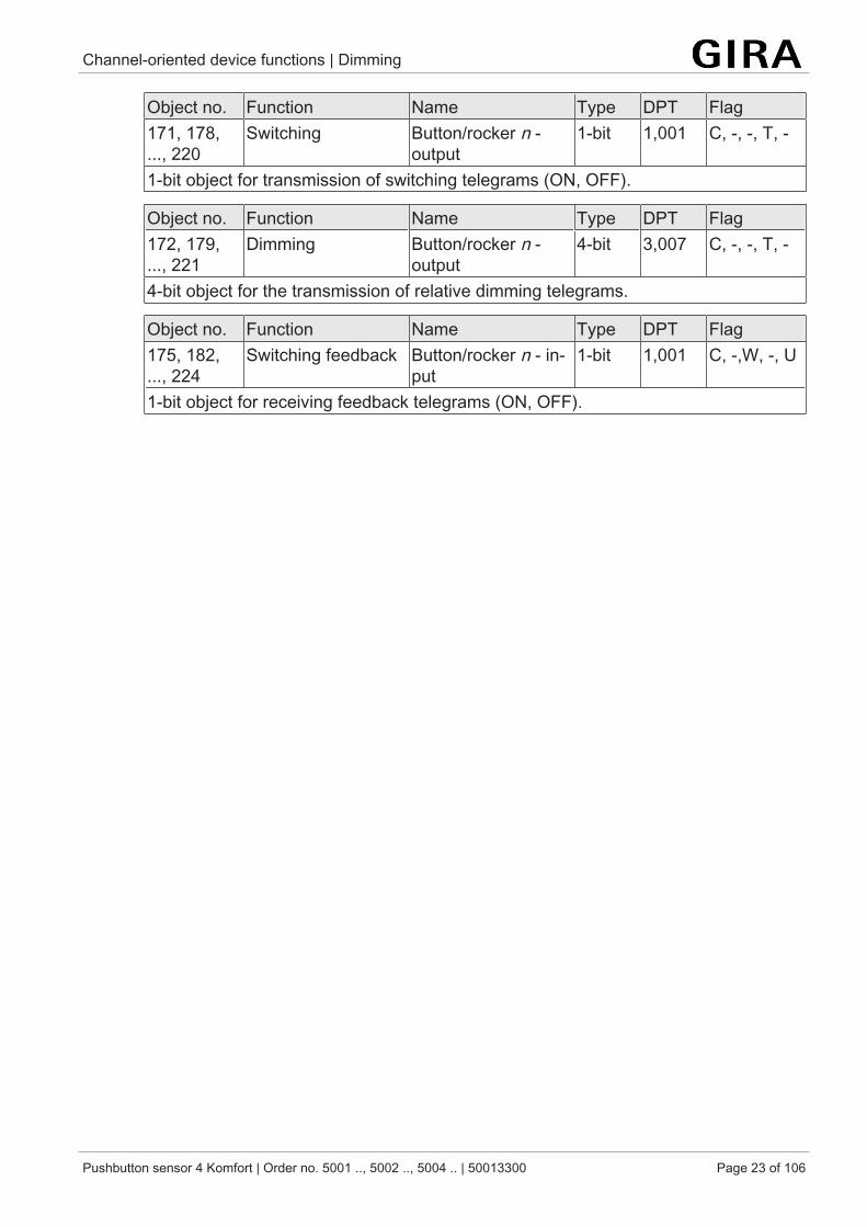
8.2.2 Object listThe following communication objects are available for the individual buttons or rock-ers, depending on the set operating concept. The object name corresponds to the se-lection for the operating concept (button or rocker). The name of the object can bespecified by the parameter "Name of ..." .
Channel-oriented device functions | Dimming
Pushbutton sensor 4 Komfort | Order no. 5001 .., 5002 .., 5004 .. | 50013300 Page 23 of 106
Object no. Function Name Type DPT Flag171, 178,..., 220
Switching Button/rocker n -output
1-bit 1,001 C, -, -, T, -
1-bit object for transmission of switching telegrams (ON, OFF).
Object no. Function Name Type DPT Flag172, 179,..., 221
Dimming Button/rocker n -output
4-bit 3,007 C, -, -, T, -
4-bit object for the transmission of relative dimming telegrams.
Object no. Function Name Type DPT Flag175, 182,..., 224
Switching feedback Button/rocker n - in-put
1-bit 1,001 C, -,W, -, U
1-bit object for receiving feedback telegrams (ON, OFF).
Channel-oriented device functions | Venetian blind
Pushbutton sensor 4 Komfort | Order no. 5001 .., 5002 .., 5004 .. | 50013300 Page 24 of 106
8.3 Venetian blindFor each rocker or each button with the function set to "Venetian blind" the ETS indic-ates the two 1-bit objects "STEP operation" and "MOVE operation".
The "Venetian blind" function distinguishes between double-area operation (UP,DOWN) and single-area operation (TOGGLE). The parameter "Command on press-ing" defines the single-area or double-area blind function.
With an operating area as a rocker, the double-surface Venetian blind function is pre-set. This means that the push-button sensor transmits a telegram for a upward move-ment, fo example after an actuation of the left actuation point and a telegram for adownward movement after an actuation of the right actuation point.In the separate buttons function, the device is preprogrammed for single-surfaceVenetian blind function. In this case, the push-button sensor alternates between thedirections of the long time telegram (TOGGLE) on each long actuation of the sensor.Several short time telegrams in succession have the same direction.
If the actuator can be controlled from several sensors, a faultless single-area opera-tion requires that the long time objects of the push-button sensors are interlinked.The push-button sensor would otherwise not be able to detect that the actuator hasbeen addressed from another sensor, in which case it would have to be actuatedtwice during the next use in order to produce the desired reaction.
The status LEDs can be configured independentlyStatus LED.
Operation concept for the Venetian blind function
For the control of Venetian blind, roller shutter, awning or similar drives, the push-but-ton sensor supports four operation concepts in which the telegrams are transmitted indifferent time sequences. The push-button sensor can therefore be used to operate awide variety of drive configurations.The different operation concepts are described in detail in the following chapter.
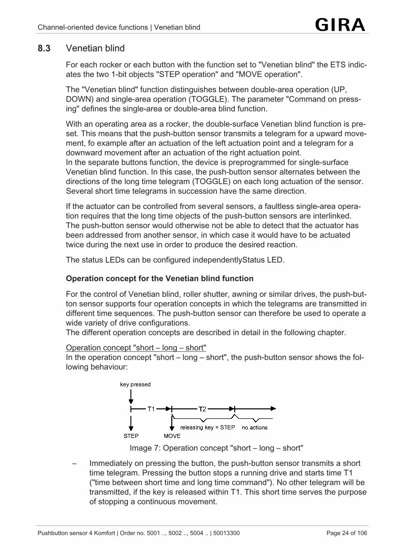
Operation concept "short – long – short"In the operation concept "short – long – short", the push-button sensor shows the fol-lowing behaviour:
Image 7: Operation concept "short – long – short"
– Immediately on pressing the button, the push-button sensor transmits a shorttime telegram. Pressing the button stops a running drive and starts time T1("time between short time and long time command"). No other telegram will betransmitted, if the key is released within T1. This short time serves the purposeof stopping a continuous movement.
Channel-oriented device functions | Venetian blind
Pushbutton sensor 4 Komfort | Order no. 5001 .., 5002 .., 5004 .. | 50013300 Page 25 of 106
The "time between short and long time command" in the push-button sensorshould be selected shorter than the short time operation of the actuator to pre-vent a jerky movement of the blind.
– If the button is kept depressed longer than T1, the push-button transmits along time telegram after the end of T1 for starting up the drive and time T2("slat adjusting time") is started.
– If the button is released within the slat adjusting time, the push-button sensorsends another short time telegram. This function is used for adjusting the slatsof a blind. The function permits stopping the slats in any position during theirrotation.The "slat adjusting time" should be chosen as required by the drive for a com-plete rotation of the slats. If the "slat adjusting time" is selected longer than thecomplete travelling time of the drive, a pushbutton function is possible as well.This means that the drive is active only when the button is kept depressed.
– If the button is kept depressed longer than T2, the push-button sensor trans-mits no further telegram. The drive remains on until the end position isreached.
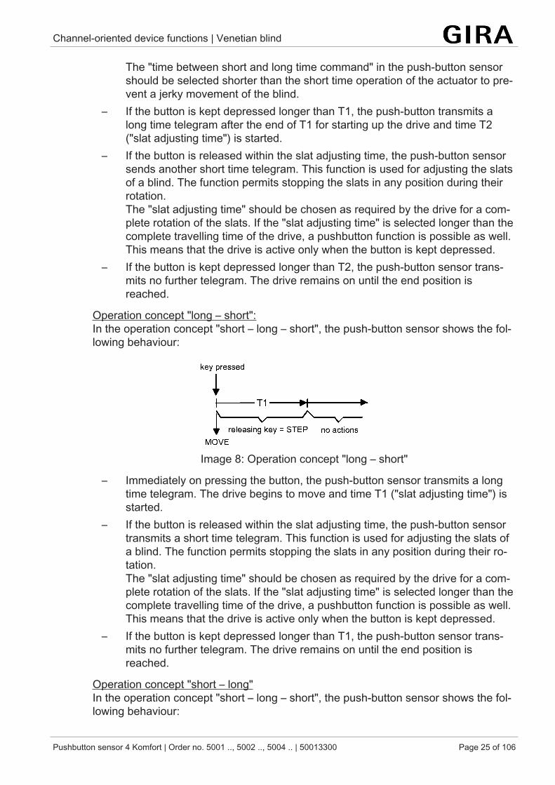
Operation concept "long – short":In the operation concept "short – long – short", the push-button sensor shows the fol-lowing behaviour:
Image 8: Operation concept "long – short"
– Immediately on pressing the button, the push-button sensor transmits a longtime telegram. The drive begins to move and time T1 ("slat adjusting time") isstarted.
– If the button is released within the slat adjusting time, the push-button sensortransmits a short time telegram. This function is used for adjusting the slats ofa blind. The function permits stopping the slats in any position during their ro-tation.The "slat adjusting time" should be chosen as required by the drive for a com-plete rotation of the slats. If the "slat adjusting time" is selected longer than thecomplete travelling time of the drive, a pushbutton function is possible as well.This means that the drive is active only when the button is kept depressed.
– If the button is kept depressed longer than T1, the push-button sensor trans-mits no further telegram. The drive remains on until the end position isreached.
Operation concept "short – long"In the operation concept "short – long – short", the push-button sensor shows the fol-lowing behaviour:
Channel-oriented device functions | Venetian blind
Pushbutton sensor 4 Komfort | Order no. 5001 .., 5002 .., 5004 .. | 50013300 Page 26 of 106
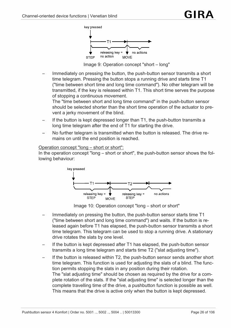
Image 9: Operation concept "short – long"
– Immediately on pressing the button, the push-button sensor transmits a shorttime telegram. Pressing the button stops a running drive and starts time T1("time between short time and long time command"). No other telegram will betransmitted, if the key is released within T1. This short time serves the purposeof stopping a continuous movement.The "time between short and long time command" in the push-button sensorshould be selected shorter than the short time operation of the actuator to pre-vent a jerky movement of the blind.
– If the button is kept depressed longer than T1, the push-button transmits along time telegram after the end of T1 for starting the drive.
– No further telegram is transmitted when the button is released. The drive re-mains on until the end position is reached.
Operation concept "long – short or short":In the operation concept "long – short or short", the push-button sensor shows the fol-lowing behaviour:
Image 10: Operation concept "long – short or short"
– Immediately on pressing the button, the push-button sensor starts time T1("time between short and long time command") and waits. If the button is re-leased again before T1 has elapsed, the push-button sensor transmits a shorttime telegram. This telegram can be used to stop a running drive. A stationarydrive rotates the slats by one level.
– If the button is kept depressed after T1 has elapsed, the push-button sensortransmits a long time telegram and starts time T2 ("slat adjusting time").
– If the button is released within T2, the push-button sensor sends another shorttime telegram. This function is used for adjusting the slats of a blind. The func-tion permits stopping the slats in any position during their rotation.The "slat adjusting time" should be chosen as required by the drive for a com-plete rotation of the slats. If the "slat adjusting time" is selected longer than thecomplete travelling time of the drive, a pushbutton function is possible as well.This means that the drive is active only when the button is kept depressed.
Channel-oriented device functions | Venetian blind
Pushbutton sensor 4 Komfort | Order no. 5001 .., 5002 .., 5004 .. | 50013300 Page 27 of 106
– If the button is kept depressed longer than T2, the push-button sensor trans-mits no further telegram. The drive remains on until the end position isreached.
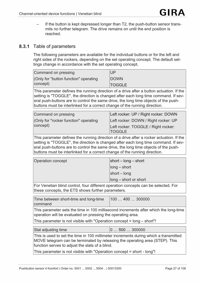
8.3.1 Table of parametersThe following parameters are available for the individual buttons or for the left andright sides of the rockers, depending on the set operating concept. The default set-tings change in accordance with the set operating concept.
Command on pressing(Only for "button function" operatingconcept)
UPDOWNTOGGLE
This parameter defines the running direction of a drive after a button actuation. If thesetting is "TOGGLE", the direction is changed after each long time command. If sev-eral push-buttons are to control the same drive, the long time objects of the push-buttons must be interlinked for a correct change of the running direction.
Command on pressing(Only for "rocker function" operatingconcept)
Left rocker: UP / Right rocker: DOWNLeft rocker: DOWN / Right rocker: UPLeft rocker: TOGGLE / Right rocker:TOGGLE
This parameter defines the running direction of a drive after a rocker actuation. If thesetting is "TOGGLE", the direction is changed after each long time command. If sev-eral push-buttons are to control the same drive, the long time objects of the push-buttons must be interlinked for a correct change of the running direction.
Operation concept short – long – shortlong – shortshort – longlong – short or short
For Venetian blind control, four different operation concepts can be selected. Forthese concepts, the ETS shows further parameters.
Time between short-time and long-timecommand
100 … 400 … 300000
This parameter sets the time in 100 millisecond increments after which the long-timeoperation will be evaluated on pressing the operating area.This parameter is not visible with "Operation concept = long – short"!
Slat adjusting time 0 … 500 … 300000This is used to set the time in 100 millimeter increments during which a transmittedMOVE telegram can be terminated by releasing the operating area (STEP). Thisfunction serves to adjust the slats of a blind.This parameter is not visible with "Operation concept = short - long"!
Channel-oriented device functions | Venetian blind
Pushbutton sensor 4 Komfort | Order no. 5001 .., 5002 .., 5004 .. | 50013300 Page 28 of 106
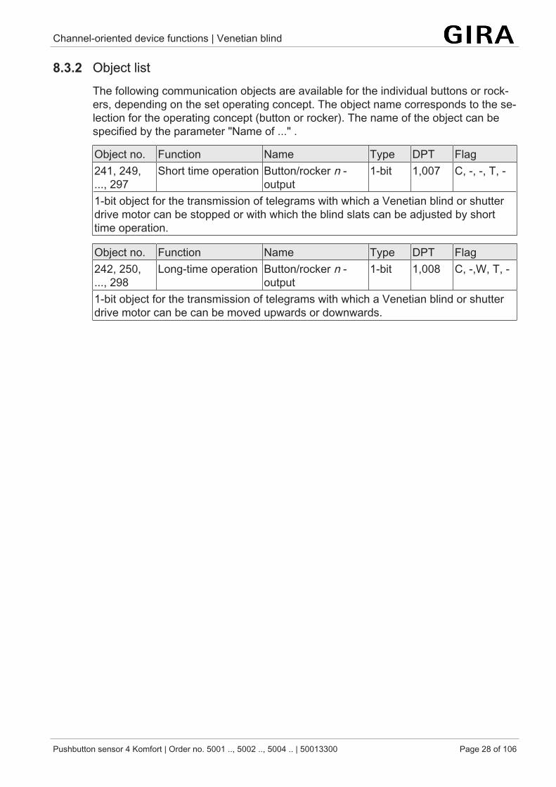
8.3.2 Object listThe following communication objects are available for the individual buttons or rock-ers, depending on the set operating concept. The object name corresponds to the se-lection for the operating concept (button or rocker). The name of the object can bespecified by the parameter "Name of ..." .
Object no. Function Name Type DPT Flag241, 249,..., 297
Short time operation Button/rocker n -output
1-bit 1,007 C, -, -, T, -
1-bit object for the transmission of telegrams with which a Venetian blind or shutterdrive motor can be stopped or with which the blind slats can be adjusted by shorttime operation.
Object no. Function Name Type DPT Flag242, 250,..., 298
Long-time operation Button/rocker n -output
1-bit 1,008 C, -,W, T, -
1-bit object for the transmission of telegrams with which a Venetian blind or shutterdrive motor can be can be moved upwards or downwards.
Channel-oriented device functions | Value transmitter
Pushbutton sensor 4 Komfort | Order no. 5001 .., 5002 .., 5004 .. | 50013300 Page 29 of 106
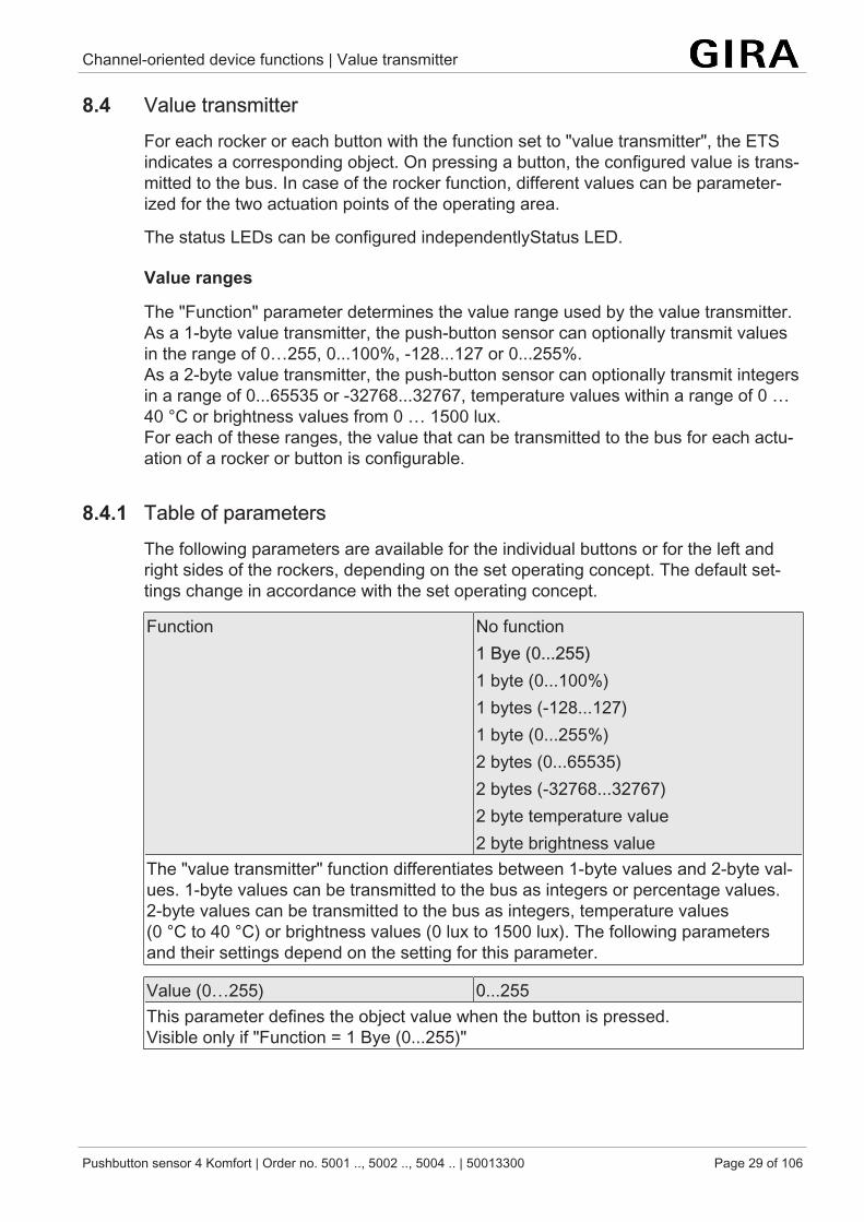
8.4 Value transmitterFor each rocker or each button with the function set to "value transmitter", the ETSindicates a corresponding object. On pressing a button, the configured value is trans-mitted to the bus. In case of the rocker function, different values can be parameter-ized for the two actuation points of the operating area.
The status LEDs can be configured independentlyStatus LED.
Value ranges
The "Function" parameter determines the value range used by the value transmitter.As a 1-byte value transmitter, the push-button sensor can optionally transmit valuesin the range of 0…255, 0...100%, -128...127 or 0...255%.As a 2-byte value transmitter, the push-button sensor can optionally transmit integersin a range of 0...65535 or -32768...32767, temperature values within a range of 0 …40 °C or brightness values from 0 … 1500 lux.For each of these ranges, the value that can be transmitted to the bus for each actu-ation of a rocker or button is configurable.
8.4.1 Table of parametersThe following parameters are available for the individual buttons or for the left andright sides of the rockers, depending on the set operating concept. The default set-tings change in accordance with the set operating concept.
Function No function1 Bye (0...255)1 byte (0...100%)1 bytes (-128...127)1 byte (0...255%)2 bytes (0...65535)2 bytes (-32768...32767)2 byte temperature value2 byte brightness value
The "value transmitter" function differentiates between 1-byte values and 2-byte val-ues. 1-byte values can be transmitted to the bus as integers or percentage values.2-byte values can be transmitted to the bus as integers, temperature values(0 °C to 40 °C) or brightness values (0 lux to 1500 lux). The following parametersand their settings depend on the setting for this parameter.
Value (0…255) 0...255This parameter defines the object value when the button is pressed.Visible only if "Function = 1 Bye (0...255)"
Channel-oriented device functions | Value transmitter
Pushbutton sensor 4 Komfort | Order no. 5001 .., 5002 .., 5004 .. | 50013300 Page 30 of 106
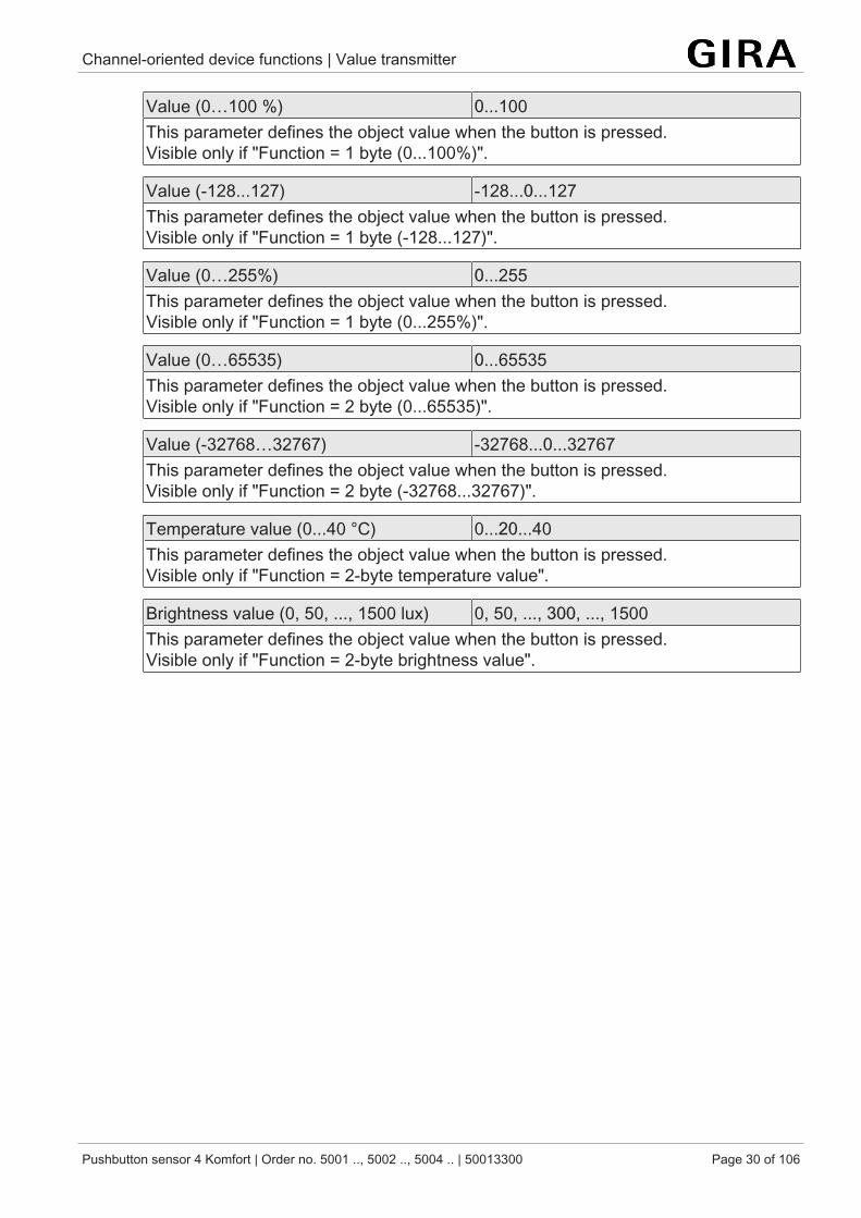
Value (0…100 %) 0...100This parameter defines the object value when the button is pressed.Visible only if "Function = 1 byte (0...100%)".
Value (-128...127) -128...0...127This parameter defines the object value when the button is pressed.Visible only if "Function = 1 byte (-128...127)".
Value (0…255%) 0...255This parameter defines the object value when the button is pressed.Visible only if "Function = 1 byte (0...255%)".
Value (0…65535) 0...65535This parameter defines the object value when the button is pressed.Visible only if "Function = 2 byte (0...65535)".
Value (-32768…32767) -32768...0...32767This parameter defines the object value when the button is pressed.Visible only if "Function = 2 byte (-32768...32767)".
Temperature value (0...40 °C) 0...20...40This parameter defines the object value when the button is pressed.Visible only if "Function = 2-byte temperature value".
Brightness value (0, 50, ..., 1500 lux) 0, 50, ..., 300, ..., 1500This parameter defines the object value when the button is pressed.Visible only if "Function = 2-byte brightness value".
Channel-oriented device functions | Value transmitter
Pushbutton sensor 4 Komfort | Order no. 5001 .., 5002 .., 5004 .. | 50013300 Page 31 of 106
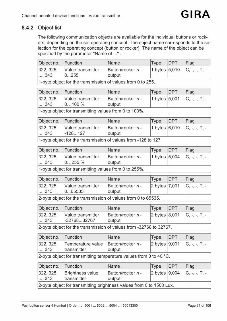
8.4.2 Object listThe following communication objects are available for the individual buttons or rock-ers, depending on the set operating concept. The object name corresponds to the se-lection for the operating concept (button or rocker). The name of the object can bespecified by the parameter "Name of ..." .
Object no. Function Name Type DPT Flag322, 325,..., 343
Value transmitter0...255
Button/rocker n -output
1 bytes 5,010 C, -, -, T, -
1-byte object for the transmission of values from 0 to 255.
Object no. Function Name Type DPT Flag322, 325,..., 343
Value transmitter0…100 %
Button/rocker n -output
1 bytes 5,001 C, -, -, T, -
1-byte object for transmitting values from 0 to 100%.
Object no. Function Name Type DPT Flag322, 325,..., 343
Value transmitter-128...127
Button/rocker n -output
1 bytes 6,010 C, -, -, T, -
1-byte object for the transmission of values from -128 to 127.
Object no. Function Name Type DPT Flag322, 325,..., 343
Value transmitter0…255 %
Button/rocker n -output
1 bytes 5,004 C, -, -, T, -
1-byte object for transmitting values from 0 to 255%.
Object no. Function Name Type DPT Flag322, 325,..., 343
Value transmitter0...65535
Button/rocker n -output
2 bytes 7,001 C, -, -, T, -
2-byte object for the transmission of values from 0 to 65535.
Object no. Function Name Type DPT Flag322, 325,..., 343
Value transmitter-32768...32767
Button/rocker n -output
2 bytes 8,001 C, -, -, T, -
2-byte object for the transmission of values from -32768 to 32767.
Object no. Function Name Type DPT Flag322, 325,..., 343
Temperature valuetransmitter
Button/rocker n -output
2 bytes 9,001 C, -, -, T, -
2-byte object for transmitting temperature values from 0 to 40 °C.
Object no. Function Name Type DPT Flag322, 325,..., 343
Brightness valuetransmitter
Button/rocker n -output
2 bytes 9,004 C, -, -, T, -
2-byte object for transmitting brightness values from 0 to 1500 Lux.
Channel-oriented device functions | Scene extension
Pushbutton sensor 4 Komfort | Order no. 5001 .., 5002 .., 5004 .. | 50013300 Page 32 of 106
8.5 Scene extensionFor each rocker or button with the function set to "scene extension unit", the ETS in-dicates the "Function" parameter which distinguishes between the following settings:
– "Scene extension without storage function",– "Scene extension with storage function",– "Recall internal scene without storage function"– "Recall internal scene with storage function".
In the scene extension function, the push-button sensor transmits a preset scenenumber (1…64) via a separate communication object to the bus after a button-press.This feature permits recalling scenes stored in other devices and also storing them, ifthe storage function is used.
The recall of an internal scene does not result in a telegram being transmitted to thebus. This is why the corresponding communication object is not displayed. This func-tion can rather be used to recall – and with the storage function also to store – the upto 8 scenes stored internally in the push button sensor.
In the setting "... without storage function", a button-press triggers the simple recall ofa scene. A long button-press has no further or additional effect.
In the setting "... with storage function", the push-button sensor monitors the length ofthe actuation. A button actuation of less than a second results in a simple recall ofthe scene as mentioned above.
After a button actuation of more than five seconds, the push-button sensor generatesa storage instruction. In the scene extension function, a storage telegram is in thiscase transmitted to the bus. If configured for the recall of an internal scene, thesensor will store the internal scene. The internal scene control module will then re-quest the current scene values for the actuator groups used from the bus.
An operation lasting between one and five seconds will be discarded as in-valid.
The status LEDs can be configured independentlyStatus LED.
Channel-oriented device functions | Scene extension
Pushbutton sensor 4 Komfort | Order no. 5001 .., 5002 .., 5004 .. | 50013300 Page 33 of 106
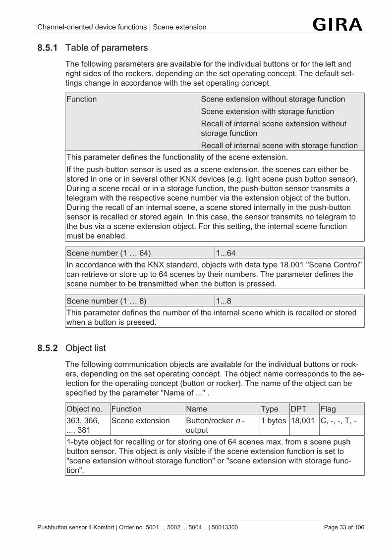
8.5.1 Table of parametersThe following parameters are available for the individual buttons or for the left andright sides of the rockers, depending on the set operating concept. The default set-tings change in accordance with the set operating concept.
Function Scene extension without storage functionScene extension with storage functionRecall of internal scene extension withoutstorage functionRecall of internal scene with storage function
This parameter defines the functionality of the scene extension.If the push-button sensor is used as a scene extension, the scenes can either bestored in one or in several other KNX devices (e.g. light scene push button sensor).During a scene recall or in a storage function, the push-button sensor transmits atelegram with the respective scene number via the extension object of the button.During the recall of an internal scene, a scene stored internally in the push-buttonsensor is recalled or stored again. In this case, the sensor transmits no telegram tothe bus via a scene extension object. For this setting, the internal scene functionmust be enabled.
Scene number (1 … 64) 1...64In accordance with the KNX standard, objects with data type 18.001 "Scene Control"can retrieve or store up to 64 scenes by their numbers. The parameter defines thescene number to be transmitted when the button is pressed.
Scene number (1 … 8) 1...8This parameter defines the number of the internal scene which is recalled or storedwhen a button is pressed.
8.5.2 Object listThe following communication objects are available for the individual buttons or rock-ers, depending on the set operating concept. The object name corresponds to the se-lection for the operating concept (button or rocker). The name of the object can bespecified by the parameter "Name of ..." .
Object no. Function Name Type DPT Flag363, 366,..., 381
Scene extension Button/rocker n -output
1 bytes 18,001 C, -, -, T, -
1-byte object for recalling or for storing one of 64 scenes max. from a scene pushbutton sensor. This object is only visible if the scene extension function is set to"scene extension without storage function" or "scene extension with storage func-tion".
Channel-oriented device functions | 2-channel operation
Pushbutton sensor 4 Komfort | Order no. 5001 .., 5002 .., 5004 .. | 50013300 Page 34 of 106
8.6 2-channel operationThe "2-channel operation" function allows two function channels to be operated witha single press of a button. In some situations it is desirable to control two differentfunctions with a single press of a button and to transmit different telegrams.
For both channels, the parameters "Function channel 1" and "Function channel 2"can be used to determine the communication object types to be used. The followingoptions are available for selection:
– 1-bit switching– Value transmitter 1 byte (0...255)– Value transmitter 1 byte (0...100%)– Value transmitter 1 byte (-128...127)– Value transmitter 1 byte (0...255%)– Value transmitter 2 byte (0...65535)– Value transmitter 2 byte (-32768...32767)– Value transmitter 2-byte temperature value– Value transmitter 2-byte brightness value– Recalling scene (external)– Recalling scene (internal)
The object value the push-button sensor is to transmit on a button actuation can beselected depending on the selected function.
The "1 bit switching" type permits selecting whether an ON or an OFF telegram is tobe transmitted or whether the object value is to be switched over (TOGGLE) andtransmitted on the press of a button.
With parameterization as a value transmitter ("1 byte ..." or "2 byte ...") the objectvalue can be selected within the value range.
"Recalling scene (...)" can be used to set the scene number to be transmitted to thebus when a button is pressed.
The status LEDs can be configured independentlyStatus LED.
Unlike in the other rocker and button functions, the application program as-signs the "Telegram acknowledge" function instead of the "Button-press dis-play" function to the status LED. In this mode, the status LED lights up for ap-prox. 250 ms with each telegram transmitted.
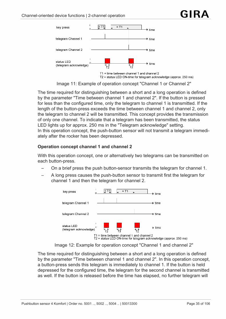
Operation concept channel 1 or channel 2
In this operation concept, exactly one telegram will be transmitted on each press of abutton.
– On a brief press the push button-sensor transmits the telegram for channel 1.– On a long press the push-button sensor transmits the telegram for channel 2.
Channel-oriented device functions | 2-channel operation
Pushbutton sensor 4 Komfort | Order no. 5001 .., 5002 .., 5004 .. | 50013300 Page 35 of 106
Image 11: Example of operation concept "Channel 1 or Channel 2"
The time required for distinguishing between a short and a long operation is definedby the parameter "Time between channel 1 and channel 2". If the button is pressedfor less than the configured time, only the telegram to channel 1 is transmitted. If thelength of the button-press exceeds the time between channel 1 and channel 2, onlythe telegram to channel 2 will be transmitted. This concept provides the transmissionof only one channel. To indicate that a telegram has been transmitted, the statusLED lights up for approx. 250 ms in the "Telegram acknowledge" setting.In this operation concept, the push-button sensor will not transmit a telegram immedi-ately after the rocker has been depressed.
Operation concept channel 1 and channel 2
With this operation concept, one or alternatively two telegrams can be transmitted oneach button-press.
– On a brief press the push button-sensor transmits the telegram for channel 1.– A long press causes the push-button sensor to transmit first the telegram for
channel 1 and then the telegram for channel 2.
Image 12: Example for operation concept "Channel 1 and channel 2"
The time required for distinguishing between a short and a long operation is definedby the parameter "Time between channel 1 and channel 2". In this operation concept,a button-press sends this telegram is immediately to channel 1. If the button is helddepressed for the configured time, the telegram for the second channel is transmittedas well. If the button is released before the time has elapsed, no further telegram will
Channel-oriented device functions | 2-channel operation
Pushbutton sensor 4 Komfort | Order no. 5001 .., 5002 .., 5004 .. | 50013300 Page 36 of 106
be transmitted. This operation concept, too, offers the configurable possibility of hav-ing the transmission of a telegram signalled by the status LED (setting "Telegram ac-knowledge").
Channel-oriented device functions | 2-channel operation
Pushbutton sensor 4 Komfort | Order no. 5001 .., 5002 .., 5004 .. | 50013300 Page 37 of 106
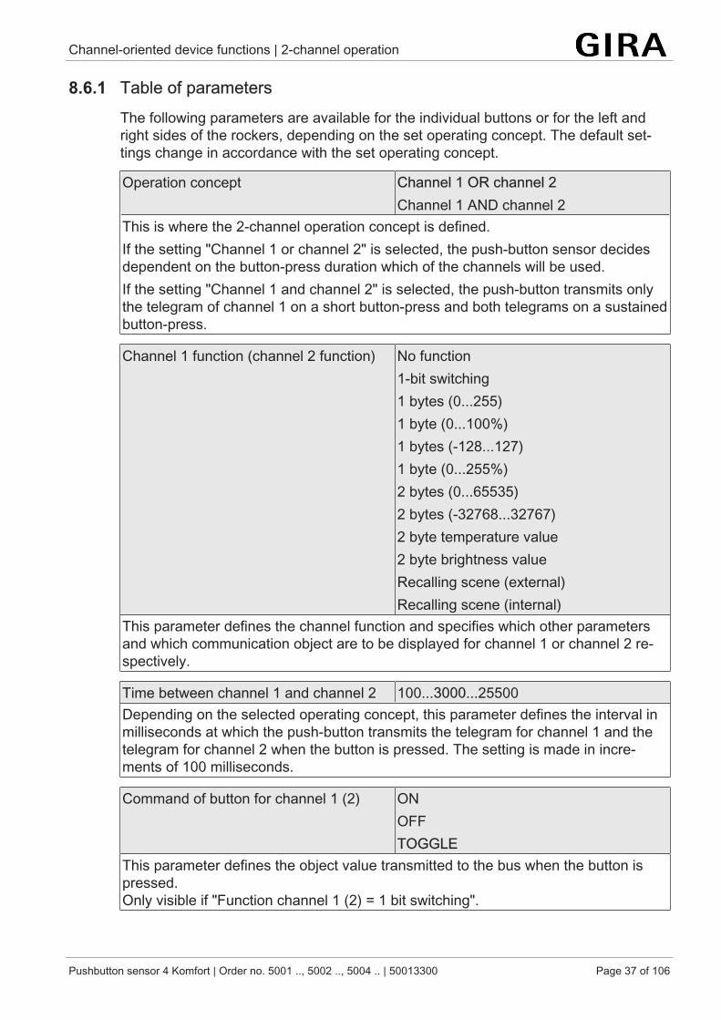
8.6.1 Table of parametersThe following parameters are available for the individual buttons or for the left andright sides of the rockers, depending on the set operating concept. The default set-tings change in accordance with the set operating concept.
Operation concept Channel 1 OR channel 2Channel 1 AND channel 2
This is where the 2-channel operation concept is defined.If the setting "Channel 1 or channel 2" is selected, the push-button sensor decidesdependent on the button-press duration which of the channels will be used.If the setting "Channel 1 and channel 2" is selected, the push-button transmits onlythe telegram of channel 1 on a short button-press and both telegrams on a sustainedbutton-press.
Channel 1 function (channel 2 function) No function1-bit switching1 bytes (0...255)1 byte (0...100%)1 bytes (-128...127)1 byte (0...255%)2 bytes (0...65535)2 bytes (-32768...32767)2 byte temperature value2 byte brightness valueRecalling scene (external)Recalling scene (internal)
This parameter defines the channel function and specifies which other parametersand which communication object are to be displayed for channel 1 or channel 2 re-spectively.
Time between channel 1 and channel 2 100...3000...25500Depending on the selected operating concept, this parameter defines the interval inmilliseconds at which the push-button transmits the telegram for channel 1 and thetelegram for channel 2 when the button is pressed. The setting is made in incre-ments of 100 milliseconds.
Command of button for channel 1 (2) ONOFFTOGGLE
This parameter defines the object value transmitted to the bus when the button ispressed.Only visible if "Function channel 1 (2) = 1 bit switching".
Channel-oriented device functions | 2-channel operation
Pushbutton sensor 4 Komfort | Order no. 5001 .., 5002 .., 5004 .. | 50013300 Page 38 of 106
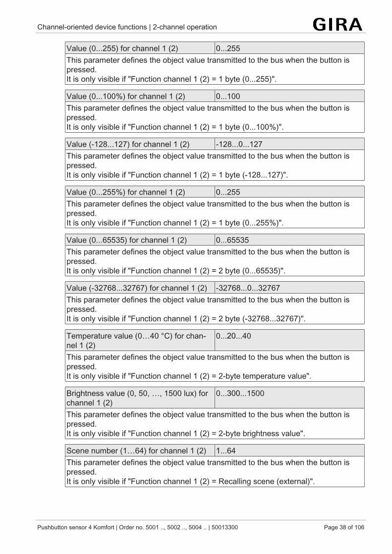
Value (0...255) for channel 1 (2) 0...255This parameter defines the object value transmitted to the bus when the button ispressed.It is only visible if "Function channel 1 (2) = 1 byte (0...255)".
Value (0...100%) for channel 1 (2) 0...100This parameter defines the object value transmitted to the bus when the button ispressed.It is only visible if "Function channel 1 (2) = 1 byte (0...100%)".
Value (-128...127) for channel 1 (2) -128...0...127This parameter defines the object value transmitted to the bus when the button ispressed.It is only visible if "Function channel 1 (2) = 1 byte (-128...127)".
Value (0...255%) for channel 1 (2) 0...255This parameter defines the object value transmitted to the bus when the button ispressed.It is only visible if "Function channel 1 (2) = 1 byte (0...255%)".
Value (0...65535) for channel 1 (2) 0...65535This parameter defines the object value transmitted to the bus when the button ispressed.It is only visible if "Function channel 1 (2) = 2 byte (0...65535)".
Value (-32768...32767) for channel 1 (2) -32768...0...32767This parameter defines the object value transmitted to the bus when the button ispressed.It is only visible if "Function channel 1 (2) = 2 byte (-32768...32767)".
Temperature value (0…40 °C) for chan-nel 1 (2)
0...20...40
This parameter defines the object value transmitted to the bus when the button ispressed.It is only visible if "Function channel 1 (2) = 2-byte temperature value".
Brightness value (0, 50, …, 1500 lux) forchannel 1 (2)
0...300...1500
This parameter defines the object value transmitted to the bus when the button ispressed.It is only visible if "Function channel 1 (2) = 2-byte brightness value".
Scene number (1…64) for channel 1 (2) 1...64This parameter defines the object value transmitted to the bus when the button ispressed.It is only visible if "Function channel 1 (2) = Recalling scene (external)".
Channel-oriented device functions | 2-channel operation
Pushbutton sensor 4 Komfort | Order no. 5001 .., 5002 .., 5004 .. | 50013300 Page 39 of 106
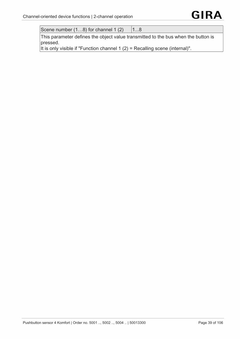
Scene number (1…8) for channel 1 (2) 1...8This parameter defines the object value transmitted to the bus when the button ispressed.It is only visible if "Function channel 1 (2) = Recalling scene (internal)".
Channel-oriented device functions | 2-channel operation
Pushbutton sensor 4 Komfort | Order no. 5001 .., 5002 .., 5004 .. | 50013300 Page 40 of 106
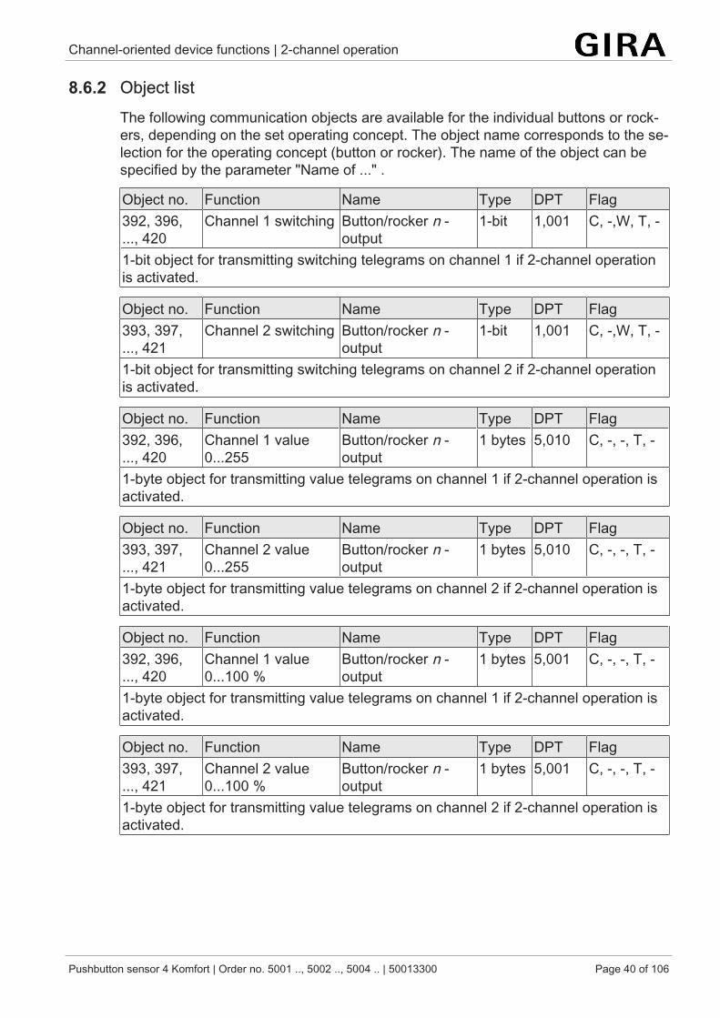
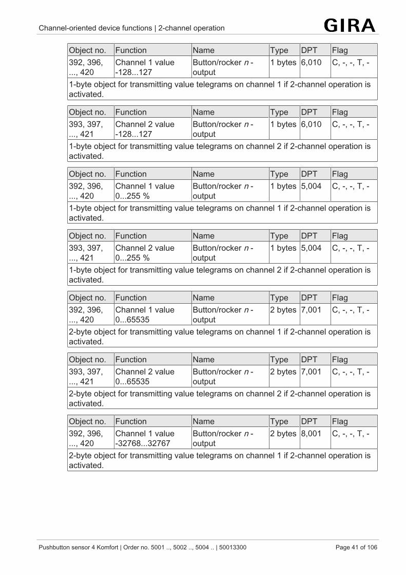
8.6.2 Object listThe following communication objects are available for the individual buttons or rock-ers, depending on the set operating concept. The object name corresponds to the se-lection for the operating concept (button or rocker). The name of the object can bespecified by the parameter "Name of ..." .
Object no. Function Name Type DPT Flag392, 396,..., 420
Channel 1 switching Button/rocker n -output
1-bit 1,001 C, -,W, T, -
1-bit object for transmitting switching telegrams on channel 1 if 2-channel operationis activated.
Object no. Function Name Type DPT Flag393, 397,..., 421
Channel 2 switching Button/rocker n -output
1-bit 1,001 C, -,W, T, -
1-bit object for transmitting switching telegrams on channel 2 if 2-channel operationis activated.
Object no. Function Name Type DPT Flag392, 396,..., 420
Channel 1 value0...255
Button/rocker n -output
1 bytes 5,010 C, -, -, T, -
1-byte object for transmitting value telegrams on channel 1 if 2-channel operation isactivated.
Object no. Function Name Type DPT Flag393, 397,..., 421
Channel 2 value0...255
Button/rocker n -output
1 bytes 5,010 C, -, -, T, -
1-byte object for transmitting value telegrams on channel 2 if 2-channel operation isactivated.
Object no. Function Name Type DPT Flag392, 396,..., 420
Channel 1 value0...100 %
Button/rocker n -output
1 bytes 5,001 C, -, -, T, -
1-byte object for transmitting value telegrams on channel 1 if 2-channel operation isactivated.
Object no. Function Name Type DPT Flag393, 397,..., 421
Channel 2 value0...100 %
Button/rocker n -output
1 bytes 5,001 C, -, -, T, -
1-byte object for transmitting value telegrams on channel 2 if 2-channel operation isactivated.
Channel-oriented device functions | 2-channel operation
Pushbutton sensor 4 Komfort | Order no. 5001 .., 5002 .., 5004 .. | 50013300 Page 41 of 106
Object no. Function Name Type DPT Flag392, 396,..., 420
Channel 1 value-128...127
Button/rocker n -output
1 bytes 6,010 C, -, -, T, -
1-byte object for transmitting value telegrams on channel 1 if 2-channel operation isactivated.
Object no. Function Name Type DPT Flag393, 397,..., 421
Channel 2 value-128...127
Button/rocker n -output
1 bytes 6,010 C, -, -, T, -
1-byte object for transmitting value telegrams on channel 2 if 2-channel operation isactivated.
Object no. Function Name Type DPT Flag392, 396,..., 420
Channel 1 value0...255 %
Button/rocker n -output
1 bytes 5,004 C, -, -, T, -
1-byte object for transmitting value telegrams on channel 1 if 2-channel operation isactivated.
Object no. Function Name Type DPT Flag393, 397,..., 421
Channel 2 value0...255 %
Button/rocker n -output
1 bytes 5,004 C, -, -, T, -
1-byte object for transmitting value telegrams on channel 2 if 2-channel operation isactivated.
Object no. Function Name Type DPT Flag392, 396,..., 420
Channel 1 value0...65535
Button/rocker n -output
2 bytes 7,001 C, -, -, T, -
2-byte object for transmitting value telegrams on channel 1 if 2-channel operation isactivated.
Object no. Function Name Type DPT Flag393, 397,..., 421
Channel 2 value0...65535
Button/rocker n -output
2 bytes 7,001 C, -, -, T, -
2-byte object for transmitting value telegrams on channel 2 if 2-channel operation isactivated.
Object no. Function Name Type DPT Flag392, 396,..., 420
Channel 1 value-32768...32767
Button/rocker n -output
2 bytes 8,001 C, -, -, T, -
2-byte object for transmitting value telegrams on channel 1 if 2-channel operation isactivated.

Channel-oriented device functions | 2-channel operation
Pushbutton sensor 4 Komfort | Order no. 5001 .., 5002 .., 5004 .. | 50013300 Page 42 of 106
Object no. Function Name Type DPT Flag393, 397,..., 421
Channel 2 value-32768...32767
Button/rocker n -output
2 bytes 8,001 C, -, -, T, -
2-byte object for transmitting value telegrams on channel 2 if 2-channel operation isactivated.
Object no. Function Name Type DPT Flag392, 396,..., 420
Channel 1 temperat-ure value
Button/rocker n -output
2 bytes 9,001 C, -, -, T, -
2-byte object for transmitting temperature values on channel 1 if 2-channel operationis activated.
Object no. Function Name Type DPT Flag393, 397,..., 421
Channel 2 temperat-ure value
Button/rocker n -output
2 bytes 9,001 C, -, -, T, -
2-byte object for transmitting temperature values on channel 2 if 2-channel operationis activated.
Object no. Function Name Type DPT Flag392, 396,..., 420
Channel 1 bright-ness value
Button/rocker n -output
2 bytes 9,004 C, -, -, T, -
2-byte object for transmitting brightness values on channel 1 if 2-channel operationis activated.
Object no. Function Name Type DPT Flag393, 397,..., 421
Channel 2 bright-ness value
Button/rocker n -output
2 bytes 9,004 C, -, -, T, -
2-byte object for transmitting brightness values on channel 2 if 2-channel operationis activated.
Object no. Function Name Type DPT Flag392, 396,..., 420
Channel 1 scene(external) 1…64
Button/rocker n -output
1 bytes 18,001 C, -, -, T, -
1-byte object for transmitting scene values on channel 1 if 2-channel operation is ac-tivated.
Object no. Function Name Type DPT Flag393, 397,..., 421
Channel 2 scene(external) 1…64
Button/rocker n -output
1 bytes 18,001 C, -, -, T, -
1-byte object for transmitting scene values on channel 2 if 2-channel operation is ac-tivated.
Channel-oriented device functions | Controller extension
Pushbutton sensor 4 Komfort | Order no. 5001 .., 5002 .., 5004 .. | 50013300 Page 43 of 106
8.7 Controller extensionThe "controller extension" button or rocker function can be used to control a KNXroom temperature controller.
The controller extension itself is not involved in the regulating process. With it, theuser can operate the single-room regulation from different places in the room. It canalso be used to adjust central heating control units which are located, for instance, ina sub-distribution unit.
Typical KNX room temperature controllers generally offer different ways of influen-cing the room temperature control:
– Operating mode switch:Switching over between different modes of operation (e.g. "Comfort","Night" ...) with different setpoint temperatures assigned to each mode by thecontroller.
– Presence status:Signalling the presence of a person in a room. The signalling may also becombined with a configured switchover in the mode of operation.
– Setpoint shift:Adjustment of the setpoint temperature via a temperature offset (DPT 9.002)or via levels (DPT 6.010).
The controller extension is operated using the push button functions of the device. Inthis way, it is possible to completely control a room temperature controller by chan-ging the operating mode, by predefining the presence function or by readjusting thesetpoint shift.
In addition, the pushbutton sensor can – independent of the controller extension func-tion – indicate the state of one or more room temperature controllers with the statusLEDs of the rockers or buttons. This feature permits the indication of operatingmodes or the bit-oriented evaluation of different status objects of controllers. In caseof the controller extension functions "Setpoint shift" or "Presence function", the statusLEDs can also signal the state of the corresponding functions directly.
The status LEDs can be configured independentlyStatus LED.
8.7.1 Operating mode switchoverSwitchover of the controller operating mode can be effected in accordance with thestandard function block for room temperature controllers defined in the KNX hand-book using two 1-byte communication objects. The operating mode can be switchedover with the normal and with the forced objects. The "Operating mode switchover"object offers a selection between the following modes:
– Comfort mode– Standby mode– Night operation– Frost/heat protection mode
Channel-oriented device functions | Controller extension
Pushbutton sensor 4 Komfort | Order no. 5001 .., 5002 .., 5004 .. | 50013300 Page 44 of 106
The "Forced object operating mode" communication object has a higher priority. Itpermits forced switching between the following modes of operation:
– Auto (normal operating mode switchover)– Comfort mode– Standby mode– Night operation– Frost/heat protection mode
The operating mode transmitted to the bus on a button press of the controller exten-sion is defined by the parameter "Operating mode on pressing". Depending on theparameterized operating concept, either a button press activates one of the abovemodes (with the "rocker function" and "button function" operating concepts), or eachbutton press toggles between two or three modes (only with the "rocker function" op-erating concept).
Notes on multiple selection:In order to ensure that a change-over from one operating mode to anotherworks properly even from different locations, the operating mode objects of thecontroller and those of all controller extensions must be interlinked and havetheir "Write" flag set. In the objects concerned, this flag is set by defaultBy checking the linked operating mode switchover feedback object, the con-troller extension knows which of the possible operating modes is active. Basedon this information, the device switches over into the next operating mode insequence when a button is pressed. In the event that none of the possible op-erating modes is active, the next operating mode in the sequence is activated.As far as switching over between the forced operating modes and "Auto" isconcerned, the device switches into the "Auto" operating mode when none ofthe configured operating modes is active.
If a status LED is to indicate the current operating mode, the status LED func-tion must be programmed for "Operating mode indication" and its status objectbe linked with the corresponding group address for operating mode change-over with normal or high priority.
8.7.2 Presence functionAll operating areas with a function set to "Presence function" have the two commu-nication objects "Presence function" and "Presence function feedback". The para-meter "Presence function on pressing" defines the object value transmitted to the buson pressing a button.
In order to ensure that the object value transmitted in the "Presence TOGGLE" set-ting is always the correct one, the presence object of the room temperature controllerand the feedback objects of the controller extensions must be interlinked and havetheir "Write" flag set. In the extension objects concerned, this flag is set by default.
The status LED of a presence function button can directly indicate the presencestatus (setting "Presence status indicator").
Channel-oriented device functions | Controller extension
Pushbutton sensor 4 Komfort | Order no. 5001 .., 5002 .., 5004 .. | 50013300 Page 45 of 106
8.7.3 Setpoint shiftThe setpoint shift is another available function of the controller extension. It makesuse of either two 2-byte communication objects with datapoint type 9.002 or two 1-byte communication objects with datapoint type 6.010 (integer with sign).
This extension function allows shifting of the basic setpoint for the temperature on aroom temperature controller by pressing a button. Operation of the extension is gen-erally the same as the operation of the main controller. A button configured as a set-point shifting button reduces or increases the setpoint shift value on each press byone step respectively. The direction of the value adjustment is defined by the para-meters "Temperature difference on pressing" or "Setpoint shift on pressing".
The status LED of a setpoint shifting button can directly indicate the setpoint shiftingstatus (setting "Setpoint value shift indicator").
Type of setpoint shift
The push-button sensor provides two options for setpoint shifting. Depending on thesetting of the parameter "Type of setpoint shift", the shift takes place via the 2-bytecommunication object "Setpoint shift specification" (acc. to KNX DPT 9.002) or viathe 1-byte-communication object "Setpoint shift specification" (acc. to KNX DPT6.010).
The setting "Via offset (DPT 9.002)" defines the temperature difference in Kelvin bywhich the setpoint temperature will be shifted up or down when the button is pressed.For a setpoint value shift, the controller extension makes use of the two communica-tion objects "Setpoint shift specification" and "Current setpoint shift". The "Currentsetpoint shift" communication object informs the extension about the current state ofthe room temperature controller. Based on this value and the respective parameter,the controller extension determines the new level size which it transmits via the "Set-point shift specification" communication object to the room temperature controller.
With the "Via levels (DPT 6.010)" setting, only the direction of the setpoint shift on theextension is defined. For a setpoint value shift, the controller extension makes use ofthe two communication objects "Setpoint shift specification" and "Current setpointshift". The "Current setpoint shift" communication object informs the extension aboutthe current state of the room temperature controller. Based on this value and the re-spective parameter, the controller extension determines the new level size which ittransmits via the "Setpoint shift specification" communication object to the room tem-perature controller.
Communication with main controller
In order to enable the push-button sensor to effect a setpoint shift in a room temper-ature controller, the controller must have input and output objects for setpoint shifting.In this case, the output object of the controller must be linked with the input object ofthe extension unit and the input object of the controller must be linked with the outputobject of the extension via an independent group address.
Channel-oriented device functions | Controller extension
Pushbutton sensor 4 Komfort | Order no. 5001 .., 5002 .., 5004 .. | 50013300 Page 46 of 106
All objects are of the same datapoint type and have the same value range. A setpointshift is interpreted by count values: a shift in positive direction is expressed by posit-ive values whereas a shift in negative direction is represented by negative object val-ues. An object value of "0" means that no setpoint shift has been activated.
Via the "Current setpoint shift" object of the controller extensions, which is linked withthe room temperature controller, the extensions are enabled to determine the currentsetpoint shift position. Starting from the value of the communication object, each but-ton-press on an extension will adjust the setpoint in the configured direction. Eachtime the setpoint is adjusted, the new shift is transmitted to the room temperaturecontroller via the "Controller extension setpoint value specification" object of the con-troller extension. The controller itself checks the received value for the minimum andmaximum temperature limits (see controller documentation) and adjusts the new set-point shift if the values are valid. When the new count value is accepted as valid, thecontroller transfers this value to its output object for setpoint shifting and retransmitsthe value to the extension as feedback.
Due to the standard data point type used as the output and input object of the con-troller extension, each extension unit is able to determine whether a shift took place,in which direction it took place and by which value (DPT 9.002) or by how manylevels (DPT 6.010) the setpoint was shifted.
In "Via levels (DPT 6.010)" function, the weighting of the respective level isdone by the controller itself.
This requires that the communication objects are connected on all controllerextensions and the controller. The feedback information from the controller en-ables the extension to continue the adjustment anytime at the right point.
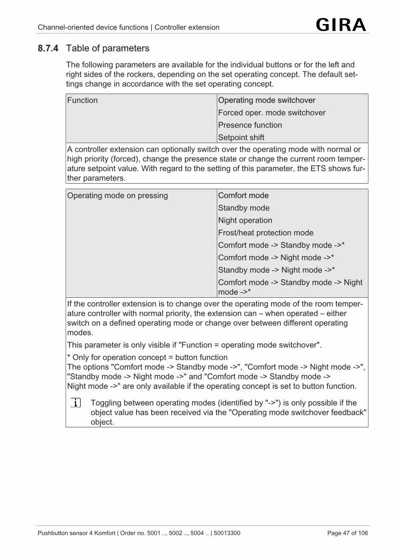
Channel-oriented device functions | Controller extension
Pushbutton sensor 4 Komfort | Order no. 5001 .., 5002 .., 5004 .. | 50013300 Page 47 of 106
8.7.4 Table of parametersThe following parameters are available for the individual buttons or for the left andright sides of the rockers, depending on the set operating concept. The default set-tings change in accordance with the set operating concept.
Function Operating mode switchoverForced oper. mode switchoverPresence functionSetpoint shift
A controller extension can optionally switch over the operating mode with normal orhigh priority (forced), change the presence state or change the current room temper-ature setpoint value. With regard to the setting of this parameter, the ETS shows fur-ther parameters.
Operating mode on pressing Comfort modeStandby modeNight operationFrost/heat protection modeComfort mode -> Standby mode ->*Comfort mode -> Night mode ->*Standby mode -> Night mode ->*Comfort mode -> Standby mode -> Nightmode ->*
If the controller extension is to change over the operating mode of the room temper-ature controller with normal priority, the extension can – when operated – eitherswitch on a defined operating mode or change over between different operatingmodes.This parameter is only visible if "Function = operating mode switchover".* Only for operation concept = button functionThe options "Comfort mode -> Standby mode ->", "Comfort mode -> Night mode ->","Standby mode -> Night mode ->" and "Comfort mode -> Standby mode ->Night mode ->" are only available if the operating concept is set to button function.
Toggling between operating modes (identified by "->") is only possible if theobject value has been received via the "Operating mode switchover feedback"object.
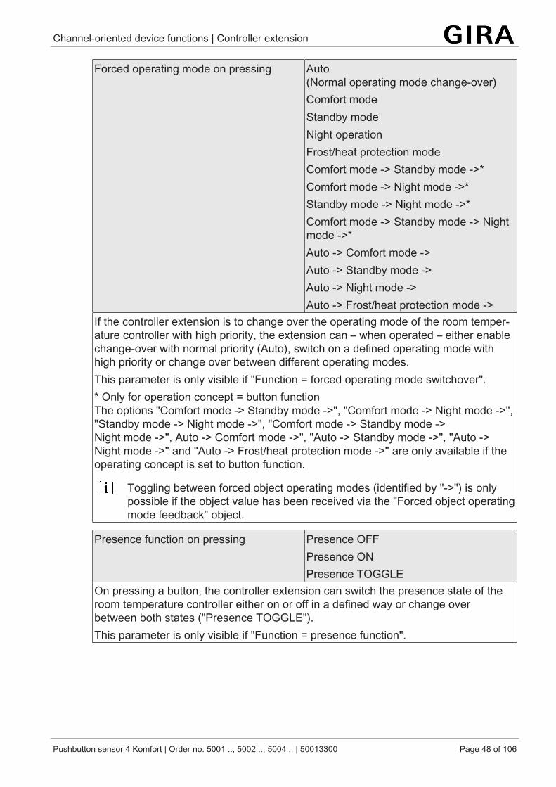
Channel-oriented device functions | Controller extension
Pushbutton sensor 4 Komfort | Order no. 5001 .., 5002 .., 5004 .. | 50013300 Page 48 of 106
Forced operating mode on pressing Auto(Normal operating mode change-over)Comfort modeStandby modeNight operationFrost/heat protection modeComfort mode -> Standby mode ->*Comfort mode -> Night mode ->*Standby mode -> Night mode ->*Comfort mode -> Standby mode -> Nightmode ->*Auto -> Comfort mode ->Auto -> Standby mode ->Auto -> Night mode ->Auto -> Frost/heat protection mode ->
If the controller extension is to change over the operating mode of the room temper-ature controller with high priority, the extension can – when operated – either enablechange-over with normal priority (Auto), switch on a defined operating mode withhigh priority or change over between different operating modes.This parameter is only visible if "Function = forced operating mode switchover".* Only for operation concept = button functionThe options "Comfort mode -> Standby mode ->", "Comfort mode -> Night mode ->","Standby mode -> Night mode ->", "Comfort mode -> Standby mode ->Night mode ->", Auto -> Comfort mode ->", "Auto -> Standby mode ->", "Auto ->Night mode ->" and "Auto -> Frost/heat protection mode ->" are only available if theoperating concept is set to button function.
Toggling between forced object operating modes (identified by "->") is onlypossible if the object value has been received via the "Forced object operatingmode feedback" object.
Presence function on pressing Presence OFFPresence ONPresence TOGGLE
On pressing a button, the controller extension can switch the presence state of theroom temperature controller either on or off in a defined way or change overbetween both states ("Presence TOGGLE").This parameter is only visible if "Function = presence function".
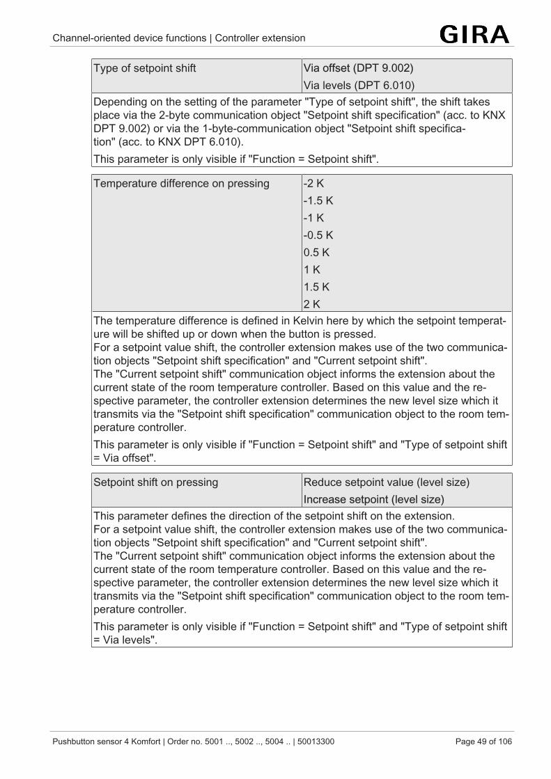
Channel-oriented device functions | Controller extension
Pushbutton sensor 4 Komfort | Order no. 5001 .., 5002 .., 5004 .. | 50013300 Page 49 of 106
Type of setpoint shift Via offset (DPT 9.002)Via levels (DPT 6.010)
Depending on the setting of the parameter "Type of setpoint shift", the shift takesplace via the 2-byte communication object "Setpoint shift specification" (acc. to KNXDPT 9.002) or via the 1-byte-communication object "Setpoint shift specifica-tion" (acc. to KNX DPT 6.010).This parameter is only visible if "Function = Setpoint shift".
Temperature difference on pressing -2 K-1.5 K-1 K-0.5 K0.5 K1 K1.5 K2 K
The temperature difference is defined in Kelvin here by which the setpoint temperat-ure will be shifted up or down when the button is pressed.For a setpoint value shift, the controller extension makes use of the two communica-tion objects "Setpoint shift specification" and "Current setpoint shift".The "Current setpoint shift" communication object informs the extension about thecurrent state of the room temperature controller. Based on this value and the re-spective parameter, the controller extension determines the new level size which ittransmits via the "Setpoint shift specification" communication object to the room tem-perature controller.This parameter is only visible if "Function = Setpoint shift" and "Type of setpoint shift= Via offset".
Setpoint shift on pressing Reduce setpoint value (level size)Increase setpoint (level size)
This parameter defines the direction of the setpoint shift on the extension.For a setpoint value shift, the controller extension makes use of the two communica-tion objects "Setpoint shift specification" and "Current setpoint shift".The "Current setpoint shift" communication object informs the extension about thecurrent state of the room temperature controller. Based on this value and the re-spective parameter, the controller extension determines the new level size which ittransmits via the "Setpoint shift specification" communication object to the room tem-perature controller.This parameter is only visible if "Function = Setpoint shift" and "Type of setpoint shift= Via levels".
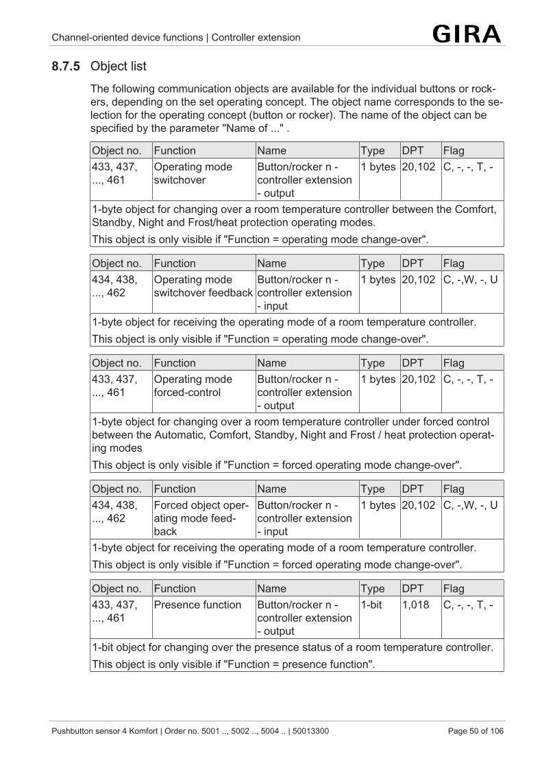
Channel-oriented device functions | Controller extension
Pushbutton sensor 4 Komfort | Order no. 5001 .., 5002 .., 5004 .. | 50013300 Page 50 of 106
8.7.5 Object listThe following communication objects are available for the individual buttons or rock-ers, depending on the set operating concept. The object name corresponds to the se-lection for the operating concept (button or rocker). The name of the object can bespecified by the parameter "Name of ..." .
Object no. Function Name Type DPT Flag433, 437,..., 461
Operating modeswitchover
Button/rocker n -controller extension- output
1 bytes 20,102 C, -, -, T, -
1-byte object for changing over a room temperature controller between the Comfort,Standby, Night and Frost/heat protection operating modes.This object is only visible if "Function = operating mode change-over".
Object no. Function Name Type DPT Flag434, 438,..., 462
Operating modeswitchover feedback
Button/rocker n -controller extension- input
1 bytes 20,102 C, -,W, -, U
1-byte object for receiving the operating mode of a room temperature controller.This object is only visible if "Function = operating mode change-over".
Object no. Function Name Type DPT Flag433, 437,..., 461
Operating modeforced-control
Button/rocker n -controller extension- output
1 bytes 20,102 C, -, -, T, -
1-byte object for changing over a room temperature controller under forced controlbetween the Automatic, Comfort, Standby, Night and Frost / heat protection operat-ing modesThis object is only visible if "Function = forced operating mode change-over".
Object no. Function Name Type DPT Flag434, 438,..., 462
Forced object oper-ating mode feed-back
Button/rocker n -controller extension- input
1 bytes 20,102 C, -,W, -, U
1-byte object for receiving the operating mode of a room temperature controller.This object is only visible if "Function = forced operating mode change-over".
Object no. Function Name Type DPT Flag433, 437,..., 461
Presence function Button/rocker n -controller extension- output
1-bit 1,018 C, -, -, T, -
1-bit object for changing over the presence status of a room temperature controller.This object is only visible if "Function = presence function".
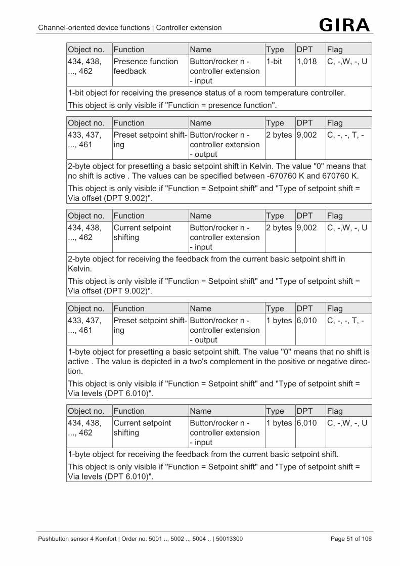
Channel-oriented device functions | Controller extension
Pushbutton sensor 4 Komfort | Order no. 5001 .., 5002 .., 5004 .. | 50013300 Page 51 of 106
Object no. Function Name Type DPT Flag434, 438,..., 462
Presence functionfeedback
Button/rocker n -controller extension- input
1-bit 1,018 C, -,W, -, U
1-bit object for receiving the presence status of a room temperature controller.This object is only visible if "Function = presence function".
Object no. Function Name Type DPT Flag433, 437,..., 461
Preset setpoint shift-ing
Button/rocker n -controller extension- output
2 bytes 9,002 C, -, -, T, -
2-byte object for presetting a basic setpoint shift in Kelvin. The value "0" means thatno shift is active . The values can be specified between -670760 K and 670760 K.This object is only visible if "Function = Setpoint shift" and "Type of setpoint shift =Via offset (DPT 9.002)".
Object no. Function Name Type DPT Flag434, 438,..., 462
Current setpointshifting
Button/rocker n -controller extension- input
2 bytes 9,002 C, -,W, -, U
2-byte object for receiving the feedback from the current basic setpoint shift inKelvin.This object is only visible if "Function = Setpoint shift" and "Type of setpoint shift =Via offset (DPT 9.002)".
Object no. Function Name Type DPT Flag433, 437,..., 461
Preset setpoint shift-ing
Button/rocker n -controller extension- output
1 bytes 6,010 C, -, -, T, -
1-byte object for presetting a basic setpoint shift. The value "0" means that no shift isactive . The value is depicted in a two's complement in the positive or negative direc-tion.This object is only visible if "Function = Setpoint shift" and "Type of setpoint shift =Via levels (DPT 6.010)".
Object no. Function Name Type DPT Flag434, 438,..., 462
Current setpointshifting
Button/rocker n -controller extension- input
1 bytes 6,010 C, -,W, -, U
1-byte object for receiving the feedback from the current basic setpoint shift.This object is only visible if "Function = Setpoint shift" and "Type of setpoint shift =Via levels (DPT 6.010)".
Channel-oriented device functions | Status LED
Pushbutton sensor 4 Komfort | Order no. 5001 .., 5002 .., 5004 .. | 50013300 Page 52 of 106
8.8 Status LEDA rocker switch on the push-button sensor is always associated with two statusLEDs. Accordingly, each status LED is assigned to a button.
The "Function of status LED" parameter on the "Button n - status LED" or "Rocker n -status LED" parameter pages defines the basic functions of this status LED. Depend-ing on the button or rocker function set, the status LED functions that can be selecteddiffer slightly.
The parameter pages for the status LED are arranged downstream of therocker or button pages and include the respective status LEDs assigned to therockers or buttons (for buttons only one status LED each / for rockers twostatus LEDs each).
Priorities of the status LED
The status LEDs operate according to a defined order of priorities.
Priority Function1 LED alarm signalling2 Superposed function3 Basic function (e.g. always ON, status display, ...)4 LED orientation lighting
Exception: A status LED will also indicate actuation if the status LED is con-trolled by the superposed function.
Channel-oriented device functions | Status LED
Pushbutton sensor 4 Komfort | Order no. 5001 .., 5002 .., 5004 .. | 50013300 Page 53 of 106
8.8.1 Basic functions
"always OFF" or "always ON"
The corresponding status LED is always switched off or always switched on depend-ing on the parameter setting.
"Button-press display" or "Telegram acknowledgement"
A status LED used as button-press display is switched on by the sensor each timethe corresponding rocker or button is pressed. The parameter "ON time of statusLEDs as actuation indicators" on the parameter page "General" specifies for howlong the LED is switched on in common for all status LEDs. The status LED lights upwhen the rocker or button is pressed even if the telegram is transmitted by the sensoronly when the button or rocker is released.With the function "2-channel operation" the option "Button-press display" is replacedby "Telegram acknowledge". In this case the status LED is illuminated when bothchannels are transmitted for about 250 ms each.
This setting cannot be selected for the rocker/button function "No function".
A status LED will also indicate actuation if the status LED is controlled by thesuperposed function.
"Status display", "Inverted status display" and "Control via separate LEDobject"
In the rocker or button functions "switching" and "dimming", the status LEDs can alsobe linked internally to the "Switching feedback" object and thus signal the currentswitching state of the actuator group.Alternatively each status LED can indicate the state of a separate LED communica-tion object. Here the LED can be switched on or off statically via the 1-bit object valuereceived, or also activated as flashing. If multiple status LEDs are configured to"flashing" and switched on, they will flash synchronously.Both for the status indication of the LED object and also for the status indication ofthe switching object it is possible to indicate or evaluate the inverted object value.After a bus reset or after ETS programming, the value of the LED object is always"OFF".
The settings "Status display" and "Inverted status display" can only be selected forthe rocker/button functions "Switching" and "Dimming".
"Operating mode display"
In this configuration the status LED has its own 1-byte communication object.For switching over between different modes of operation, new room temperature con-troller can make use of two communication objects of the20.102 "HVAC-Mode" data type. One of these objects can switch over with normalpriority between the "Comfort", "Standby", "Night", "Frost/heat protection" operatingmodes. The second object has a higher priority. It permits switching over between"Automatic", "Comfort", "Standby", "Night", "Frost/heat protection". Automatic meansin this case that the object with the lower priority is active.
Channel-oriented device functions | Status LED
Pushbutton sensor 4 Komfort | Order no. 5001 .., 5002 .., 5004 .. | 50013300 Page 54 of 106
If a status LED is to indicate the operating mode, the communication object of thestatus LED must be linked with the matching object of a room temperature controller(e. g. Controller status). The desired operating mode which the LED is to indicate canthen be selected with the parameter "Status LED on with". The LED is then lit upwhen the corresponding operating mode has been activated at the controller.After a bus reset or after ETS programming, the value of the LED object is always"0" (automatic).
"Controller status display"
The status LED can indicate the controller status in the data formats "KNX-compliant"or "Controller general". According to parameterization, the "Controller status - KNX-compliant" or "Controller status - Controller general" object is proposed. These ob-jects should be connected via group addresses to the communication objects of themain controller with the same functions.The status objects combine different informations. The "Status LED on with" para-meter is used to select what information should be evaluated and displayed via thestatus LED.
The following can be selected with "KNX-compliant":– Controller error status ("0" = no error / "1" = error)– Operating mode ("0" = Cooling / "1" = Heating)– Controller disabled ("0" = Controller enabled / "1" = Controller disabled)– Frost alarm ("0" = Frost protection temperature exceeded / "1" = Frost protec-
tion temperature undershot)– Heat alarm ("0" = Heat protection temperature exceeded / "1" = Heat protec-
tion temperature undershot)
The following can be selected with "Controller general":– Comfort mode (Is active if the "Comfort" operating mode or a comfort exten-
sion is activated.)– Standby mode (Is active if the "Standby" operating mode is activated.)– Night mode (Is active if the "Night" operating mode is activated.)– Frost/heat protection mode (Is active if the "Frost/heat protection" operating
mode is activated.)– Controller disabled (Is active if controller disable is activated (dew point
mode).)– Heating/cooling (Is active if heating is activated and inactive if cooling is activ-
ated. Is usually inactive with controller disabled.)– Controller inactive (Is active in the "Heating and cooling" operating mode when
the measured room temperature lies within the deadband. This status informa-tion is as a rule always "0" for the individual operating modes "heating" or"cooling"! Is inactive if controller is disabled.)
– Frost alarm (Is active if the measured room temperature reaches or drops be-low + 5 °C.)
Channel-oriented device functions | Status LED
Pushbutton sensor 4 Komfort | Order no. 5001 .., 5002 .., 5004 .. | 50013300 Page 55 of 106
"Presence status display" and "Inverted presence status display"
When the presence status is displayed the LED evaluates the value of the object"Feedback presence function" and switches either on or off, depending on the para-meter configuration in the ETS.
This setting can only be selected for the rocker/button functions "Controller extension- Presence function".
"Setpoint value shift display"
When a setpoint shift is indicated the LED evaluates the value of the "Current set-point shift" object and switches either on or off, depending on the parameter configur-ation in the ETS.
This setting can only be selected for the rocker/button functions "Controller extension- Setpoint shift".
Besides the functions that can be set separately for each status LED, all statusLEDs are also used for LED alarm signalling. If this is active, all LEDs of thepush button sensor flash simultaneously. After deactivation of the alarm sig-nalling, all LEDs will immediately return to the state corresponding to their con-figuration and communication objectsLED alarm signalling.
Besides the functions that can be set separately for each status LED, all statusLEDs are also used for LED orientation lighting. Depending on the configura-tion, the LED orientation lighting function will be executed with low priorityLEDorientation lighting.
8.8.2 Colour settingsThe colour of the status LEDs can be adjusted. The colour in the ETS can be selec-ted from red, green, blue, yellow, cyan, orange, violet and white. In the colour config-uration a distinction is made between whether all of the status LEDs of the push-but-ton sensor have the same colour (common colour setting), or whether alternativelyvarious colours can be configured for each status LED (separate colour setting). Thedifference is as follows:
– All status LEDs have the same colour.If common colour setting is desired, then the parameter "Colour selection of allstatus LEDs" on parameter page "General" must be configured. The statusLEDs light up in the configured colour when they are subsequently switchedon in normal operation of the push-button sensor in accordance with the basicconfiguration "Function of the status LED".The status LEDs may light up in a different colour if they are overridden by thesuperposed function of if LED alarm signalling or LED orientation lighting is ac-tivated.
– The status LEDs have various colours.
Channel-oriented device functions | Status LED
Pushbutton sensor 4 Komfort | Order no. 5001 .., 5002 .., 5004 .. | 50013300 Page 56 of 106
If separate colour setting is desired, then the parameter "Colour selection of allstatus LEDs" on parameter page "General" must be configured to the setting"Colour selection per rocker switch/button". In this case additional parametersbecome visible on the parameter pages of the individual status LEDs. Theparameters "Colour of the status LED" can then be used individually to definethe desired colour for each status LED. The status LED lights up in the con-figured colour when it is subsequently switched on in normal operation of thepush-button sensor in accordance with the basic configuration "Function of thestatus LED".
Superposed function
Additionally, a superposed function can be enabled for each status LED. The super-posed function allows for a colour change of the status LED during device operation.It is also possible here to change the display function.
A status LED will also indicate actuation if the status LED is controlled by thesuperposed function.
The superposed function of a status LED is controlled by a separate communicationobject. The device provides the two following options for controlling the superposedfunction:
– Control via separate LED object (1 bit)– Control via separate LED object (1 byte)
Depending on the superposed function selected, the device provides either a1-bit object or a 1-byte object.
If control via the 1-bit object is selected, the superimposed function is defined in theETS parameters. You can use the parameters to set whether the superposed func-tion will be switched on or off via a 1-telegram or a 0-telegram, and whether thestatus LED will statically be switched on or flash with the superposed functionswitched on. You can additionally set a separate colour for the superposed functionin which the status LED will light up when the superposed function is switched on.When a superposed function is switched off the status LED will be activated accord-ing to its basic configuration (regular colour and display function).
If control via the 1-byte object is selected, the superposed function is defined by thebit coding of the 1-byte communication object. No other parameters are available inthe in the ETS. The bit coding of the 1-byte communication object "Superposed func-tion" is shown in the table below.
Value of the telegram Superposed function of the status LED0dec Superposed function is deactivated. Status LED has
standard colours and display function.1dec Lights up white2dec Flashes white3dec Lights up red4dec Flashes red
Channel-oriented device functions | Status LED
Pushbutton sensor 4 Komfort | Order no. 5001 .., 5002 .., 5004 .. | 50013300 Page 57 of 106
Value of the telegram Superposed function of the status LED5dec Lights up green6dec Flashes green7dec Lights up blue8dec Flashing blue9dec Lights up yellow10dec Flashes yellow11dec Lights up cyan12dec Flashes cyan13dec Lights up orange14dec Flashes orange15dec Lights up violet16dec Flashes violet
The superposed function is initially always inactive after a device reset. Thesuperposed function is only executed when a telegram is received via the cor-responding object.
Regardless of the basic configuration of the status LED and the superposedfunction, the LEDs always flash red when an LED alarm message is active. AnLED alarm message has a higher priority and thus overrides the basic displayand the superposed function. After deactivation of the alarm signalling, allLEDs will immediately return to the state corresponding to their configurationand communication objects.
During colour configuration it must be ensured that different colours are con-figured for the basic display and the superposed function. If this is not done(the colours are the same), then when the display is static it is not possible todetermine which display function is being indicated.
During flashing the status LED switches cyclically between the "switched-on"and "switched-off" states. No colour change is performed between the regularcolour and the superposed colour.
8.8.3 Brightness settingsThe brightness of all status LEDs is defined in the ETS. The "Brightness of all statusLEDs" parameter on the "General" parameter page can be used to set the regularbrightness of all status LEDs in 6 levels (level 0 = OFF, level 1 = dark, ...,level 5 = bright).
Optionally the brightness can be changed during operation of the push-buttonsensor, controlled by the LED night reductionLED night reduction.
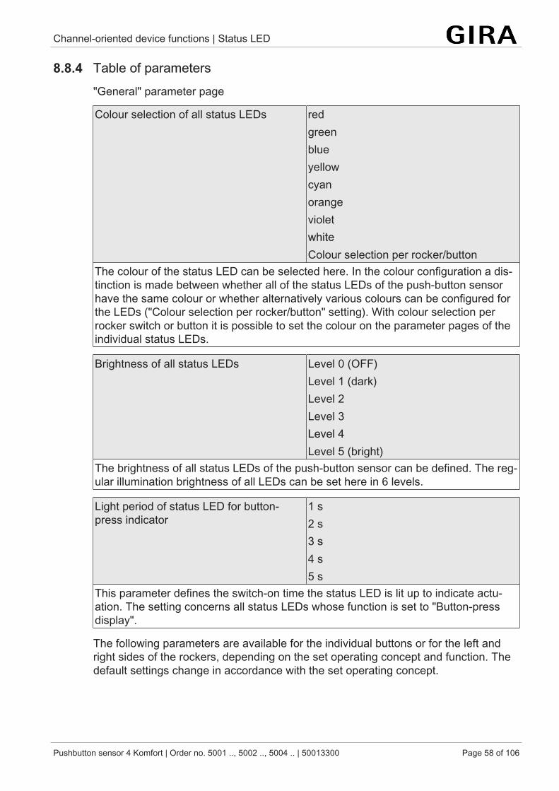
Channel-oriented device functions | Status LED
Pushbutton sensor 4 Komfort | Order no. 5001 .., 5002 .., 5004 .. | 50013300 Page 58 of 106
8.8.4 Table of parameters"General" parameter page
Colour selection of all status LEDs redgreenblueyellowcyanorangevioletwhiteColour selection per rocker/button
The colour of the status LED can be selected here. In the colour configuration a dis-tinction is made between whether all of the status LEDs of the push-button sensorhave the same colour or whether alternatively various colours can be configured forthe LEDs ("Colour selection per rocker/button" setting). With colour selection perrocker switch or button it is possible to set the colour on the parameter pages of theindividual status LEDs.
Brightness of all status LEDs Level 0 (OFF)Level 1 (dark)Level 2Level 3Level 4Level 5 (bright)
The brightness of all status LEDs of the push-button sensor can be defined. The reg-ular illumination brightness of all LEDs can be set here in 6 levels.
Light period of status LED for button-press indicator
1 s2 s3 s4 s5 s
This parameter defines the switch-on time the status LED is lit up to indicate actu-ation. The setting concerns all status LEDs whose function is set to "Button-pressdisplay".
The following parameters are available for the individual buttons or for the left andright sides of the rockers, depending on the set operating concept and function. Thedefault settings change in accordance with the set operating concept.
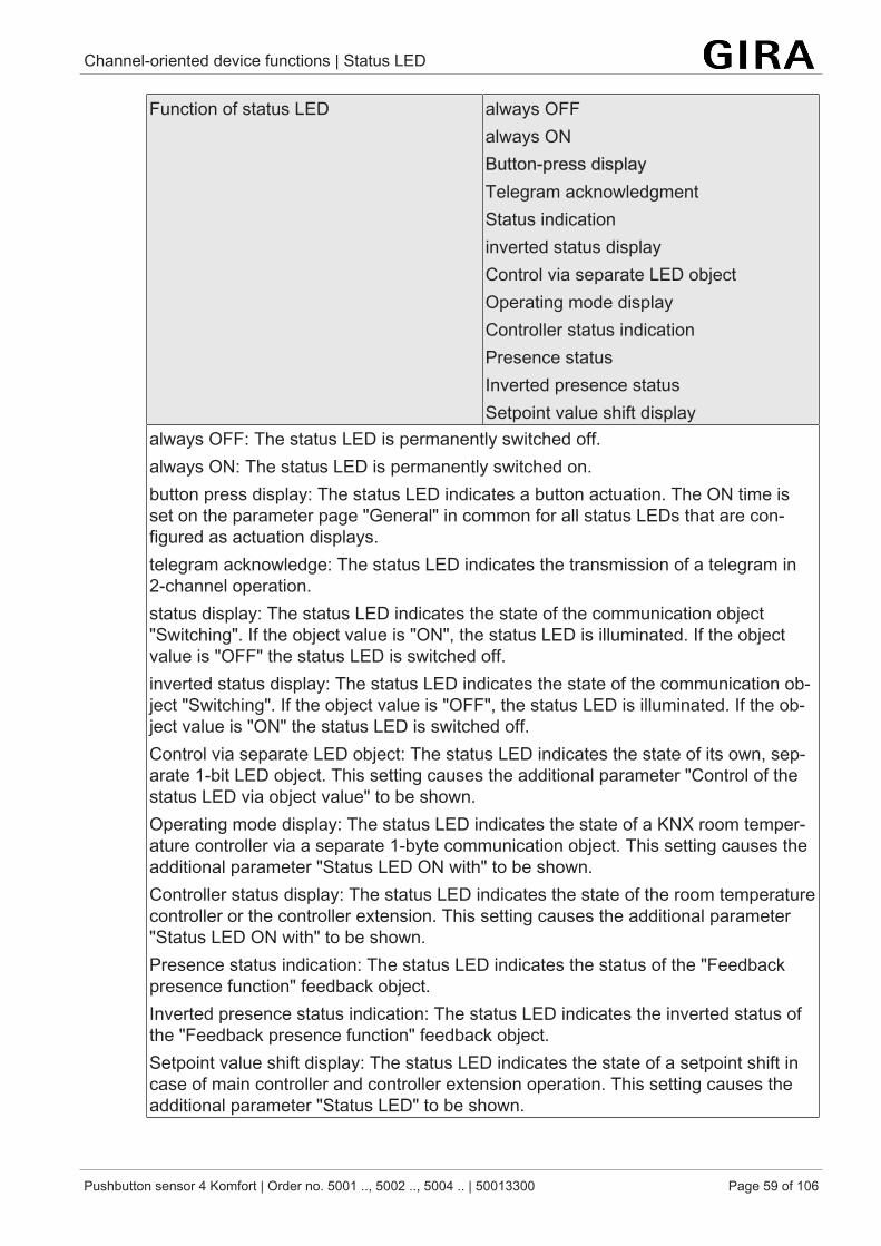
Channel-oriented device functions | Status LED
Pushbutton sensor 4 Komfort | Order no. 5001 .., 5002 .., 5004 .. | 50013300 Page 59 of 106
Function of status LED always OFFalways ONButton-press displayTelegram acknowledgmentStatus indicationinverted status displayControl via separate LED objectOperating mode displayController status indicationPresence statusInverted presence statusSetpoint value shift display
always OFF: The status LED is permanently switched off.always ON: The status LED is permanently switched on.button press display: The status LED indicates a button actuation. The ON time isset on the parameter page "General" in common for all status LEDs that are con-figured as actuation displays.telegram acknowledge: The status LED indicates the transmission of a telegram in2-channel operation.status display: The status LED indicates the state of the communication object"Switching". If the object value is "ON", the status LED is illuminated. If the objectvalue is "OFF" the status LED is switched off.inverted status display: The status LED indicates the state of the communication ob-ject "Switching". If the object value is "OFF", the status LED is illuminated. If the ob-ject value is "ON" the status LED is switched off.Control via separate LED object: The status LED indicates the state of its own, sep-arate 1-bit LED object. This setting causes the additional parameter "Control of thestatus LED via object value" to be shown.Operating mode display: The status LED indicates the state of a KNX room temper-ature controller via a separate 1-byte communication object. This setting causes theadditional parameter "Status LED ON with" to be shown.Controller status display: The status LED indicates the state of the room temperaturecontroller or the controller extension. This setting causes the additional parameter"Status LED ON with" to be shown.Presence status indication: The status LED indicates the status of the "Feedbackpresence function" feedback object.Inverted presence status indication: The status LED indicates the inverted status ofthe "Feedback presence function" feedback object.Setpoint value shift display: The status LED indicates the state of a setpoint shift incase of main controller and controller extension operation. This setting causes theadditional parameter "Status LED" to be shown.
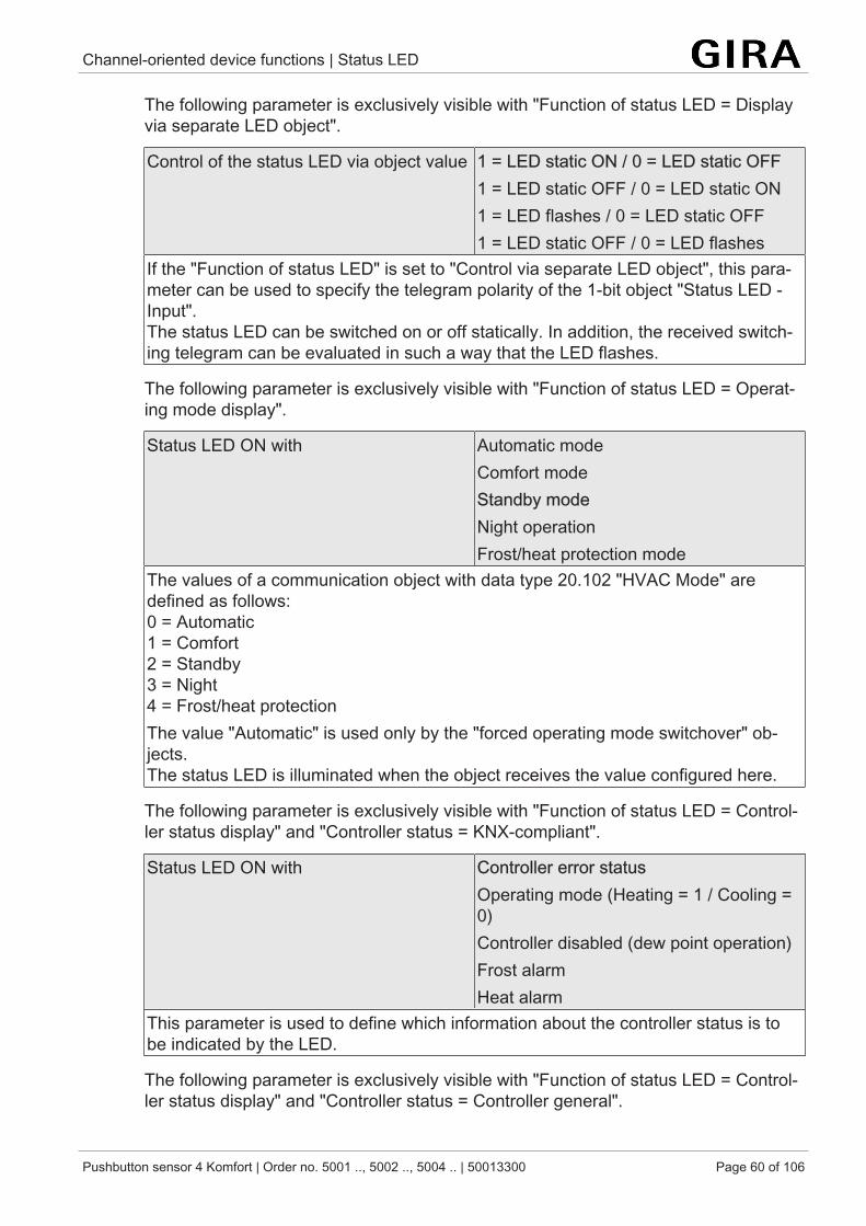
Channel-oriented device functions | Status LED
Pushbutton sensor 4 Komfort | Order no. 5001 .., 5002 .., 5004 .. | 50013300 Page 60 of 106
The following parameter is exclusively visible with "Function of status LED = Displayvia separate LED object".
Control of the status LED via object value 1 = LED static ON / 0 = LED static OFF1 = LED static OFF / 0 = LED static ON1 = LED flashes / 0 = LED static OFF1 = LED static OFF / 0 = LED flashes
If the "Function of status LED" is set to "Control via separate LED object", this para-meter can be used to specify the telegram polarity of the 1-bit object "Status LED -Input".The status LED can be switched on or off statically. In addition, the received switch-ing telegram can be evaluated in such a way that the LED flashes.
The following parameter is exclusively visible with "Function of status LED = Operat-ing mode display".
Status LED ON with Automatic modeComfort modeStandby modeNight operationFrost/heat protection mode
The values of a communication object with data type 20.102 "HVAC Mode" aredefined as follows:0 = Automatic1 = Comfort2 = Standby3 = Night4 = Frost/heat protectionThe value "Automatic" is used only by the "forced operating mode switchover" ob-jects.The status LED is illuminated when the object receives the value configured here.
The following parameter is exclusively visible with "Function of status LED = Control-ler status display" and "Controller status = KNX-compliant".
Status LED ON with Controller error statusOperating mode (Heating = 1 / Cooling =0)Controller disabled (dew point operation)Frost alarmHeat alarm
This parameter is used to define which information about the controller status is tobe indicated by the LED.
The following parameter is exclusively visible with "Function of status LED = Control-ler status display" and "Controller status = Controller general".
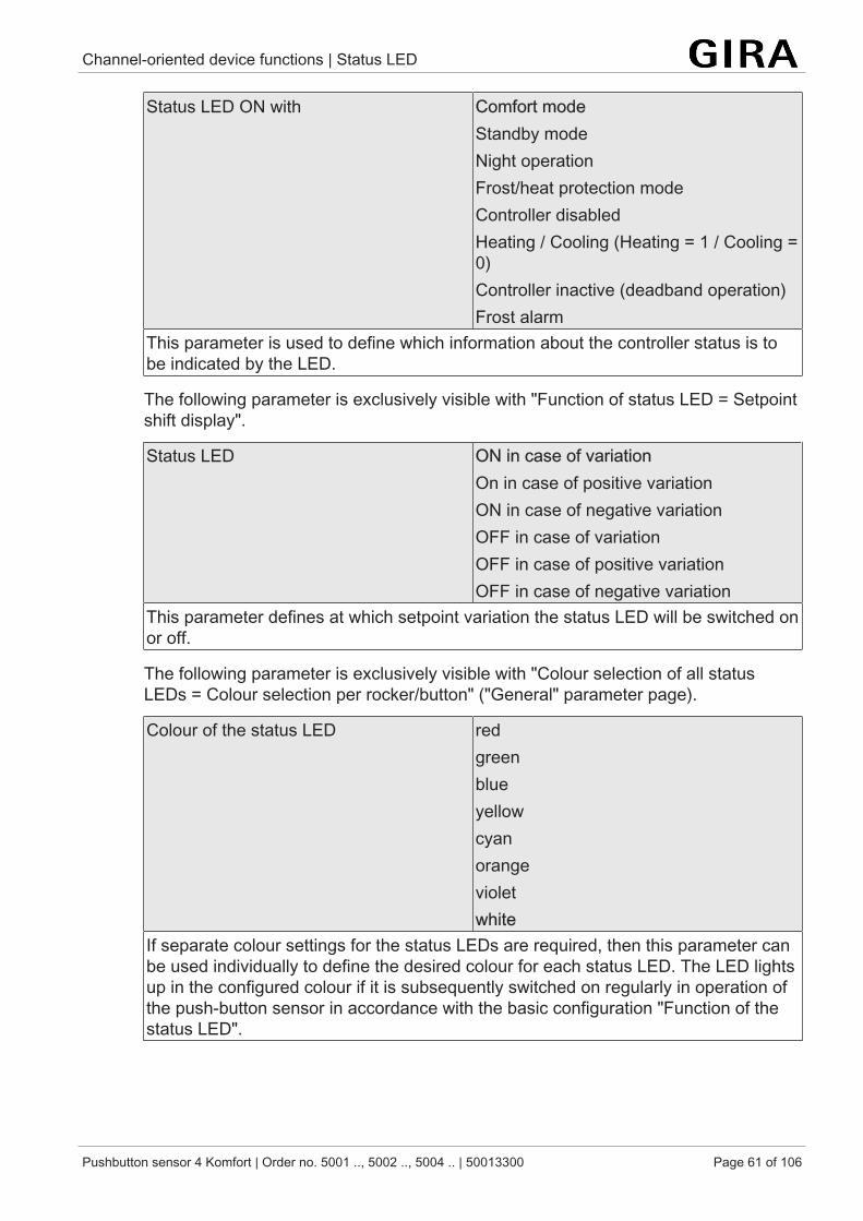
Channel-oriented device functions | Status LED
Pushbutton sensor 4 Komfort | Order no. 5001 .., 5002 .., 5004 .. | 50013300 Page 61 of 106
Status LED ON with Comfort modeStandby modeNight operationFrost/heat protection modeController disabledHeating / Cooling (Heating = 1 / Cooling =0)Controller inactive (deadband operation)Frost alarm
This parameter is used to define which information about the controller status is tobe indicated by the LED.
The following parameter is exclusively visible with "Function of status LED = Setpointshift display".
Status LED ON in case of variationOn in case of positive variationON in case of negative variationOFF in case of variationOFF in case of positive variationOFF in case of negative variation
This parameter defines at which setpoint variation the status LED will be switched onor off.
The following parameter is exclusively visible with "Colour selection of all statusLEDs = Colour selection per rocker/button" ("General" parameter page).
Colour of the status LED redgreenblueyellowcyanorangevioletwhite
If separate colour settings for the status LEDs are required, then this parameter canbe used individually to define the desired colour for each status LED. The LED lightsup in the configured colour if it is subsequently switched on regularly in operation ofthe push-button sensor in accordance with the basic configuration "Function of thestatus LED".
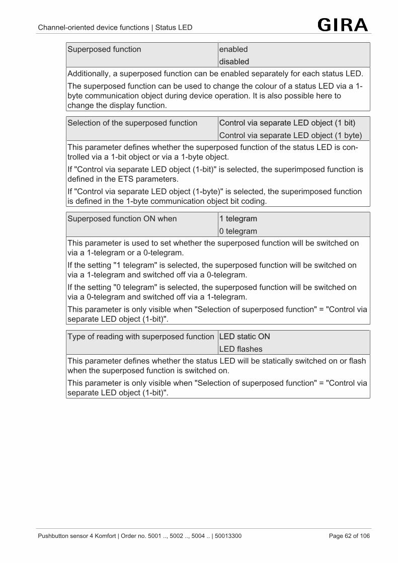
Channel-oriented device functions | Status LED
Pushbutton sensor 4 Komfort | Order no. 5001 .., 5002 .., 5004 .. | 50013300 Page 62 of 106
Superposed function enableddisabled
Additionally, a superposed function can be enabled separately for each status LED.The superposed function can be used to change the colour of a status LED via a 1-byte communication object during device operation. It is also possible here tochange the display function.
Selection of the superposed function Control via separate LED object (1 bit)Control via separate LED object (1 byte)
This parameter defines whether the superposed function of the status LED is con-trolled via a 1-bit object or via a 1-byte object.If "Control via separate LED object (1-bit)" is selected, the superimposed function isdefined in the ETS parameters.If "Control via separate LED object (1-byte)" is selected, the superimposed functionis defined in the 1-byte communication object bit coding.
Superposed function ON when 1 telegram0 telegram
This parameter is used to set whether the superposed function will be switched onvia a 1-telegram or a 0-telegram.If the setting "1 telegram" is selected, the superposed function will be switched onvia a 1-telegram and switched off via a 0-telegram.If the setting "0 telegram" is selected, the superposed function will be switched onvia a 0-telegram and switched off via a 1-telegram.This parameter is only visible when "Selection of superposed function" = "Control viaseparate LED object (1-bit)".
Type of reading with superposed function LED static ONLED flashes
This parameter defines whether the status LED will be statically switched on or flashwhen the superposed function is switched on.This parameter is only visible when "Selection of superposed function" = "Control viaseparate LED object (1-bit)".
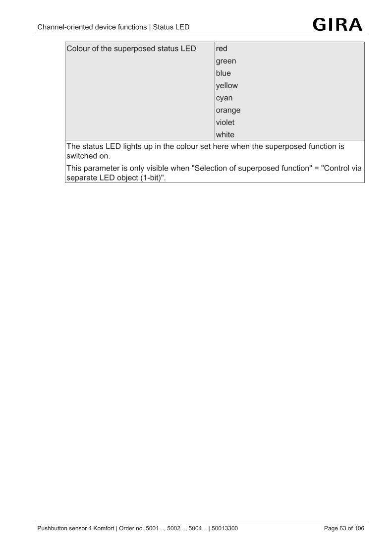
Channel-oriented device functions | Status LED
Pushbutton sensor 4 Komfort | Order no. 5001 .., 5002 .., 5004 .. | 50013300 Page 63 of 106
Colour of the superposed status LED redgreenblueyellowcyanorangevioletwhite
The status LED lights up in the colour set here when the superposed function isswitched on.This parameter is only visible when "Selection of superposed function" = "Control viaseparate LED object (1-bit)".
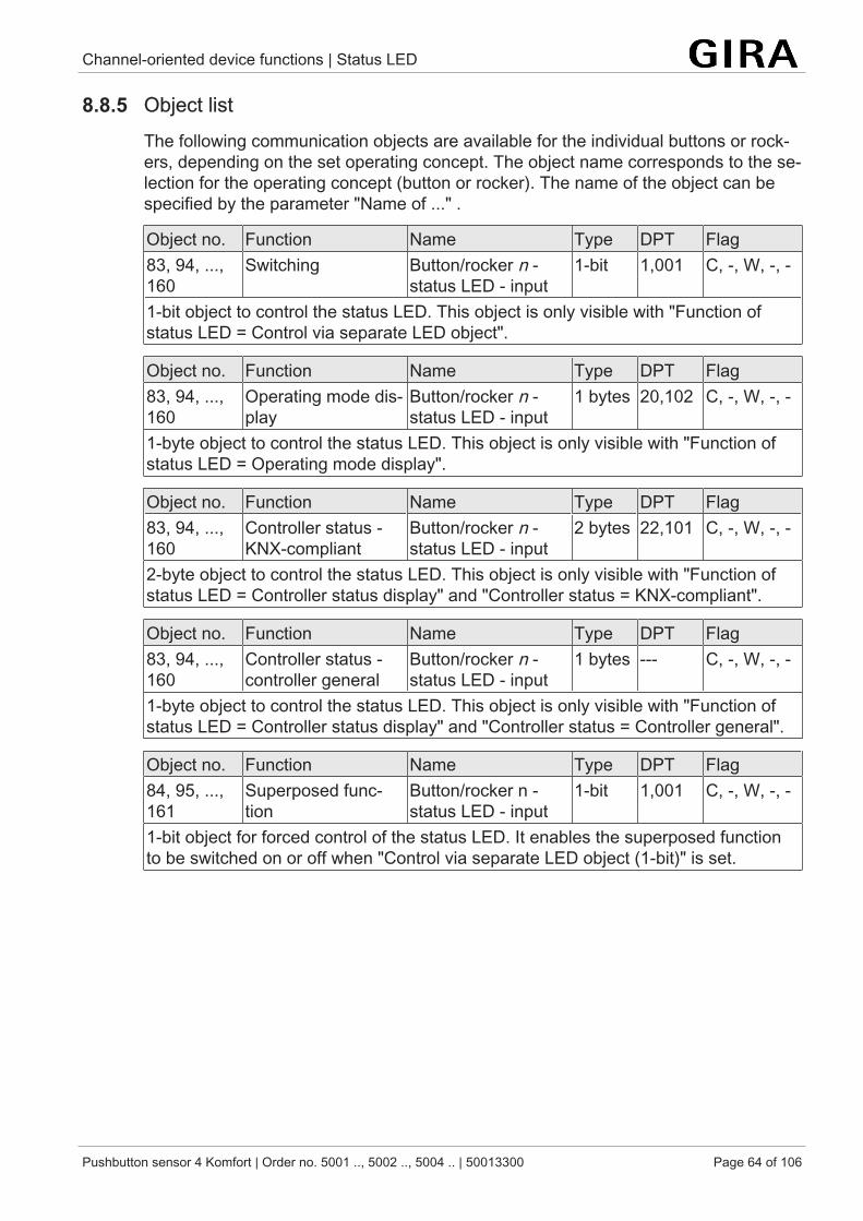
Channel-oriented device functions | Status LED
Pushbutton sensor 4 Komfort | Order no. 5001 .., 5002 .., 5004 .. | 50013300 Page 64 of 106
8.8.5 Object listThe following communication objects are available for the individual buttons or rock-ers, depending on the set operating concept. The object name corresponds to the se-lection for the operating concept (button or rocker). The name of the object can bespecified by the parameter "Name of ..." .
Object no. Function Name Type DPT Flag83, 94, ...,160
Switching Button/rocker n -status LED - input
1-bit 1,001 C, -, W, -, -
1-bit object to control the status LED. This object is only visible with "Function ofstatus LED = Control via separate LED object".
Object no. Function Name Type DPT Flag83, 94, ...,160
Operating mode dis-play
Button/rocker n -status LED - input
1 bytes 20,102 C, -, W, -, -
1-byte object to control the status LED. This object is only visible with "Function ofstatus LED = Operating mode display".
Object no. Function Name Type DPT Flag83, 94, ...,160
Controller status -KNX-compliant
Button/rocker n -status LED - input
2 bytes 22,101 C, -, W, -, -
2-byte object to control the status LED. This object is only visible with "Function ofstatus LED = Controller status display" and "Controller status = KNX-compliant".
Object no. Function Name Type DPT Flag83, 94, ...,160
Controller status -controller general
Button/rocker n -status LED - input
1 bytes --- C, -, W, -, -
1-byte object to control the status LED. This object is only visible with "Function ofstatus LED = Controller status display" and "Controller status = Controller general".
Object no. Function Name Type DPT Flag84, 95, ...,161
Superposed func-tion
Button/rocker n -status LED - input
1-bit 1,001 C, -, W, -, -
1-bit object for forced control of the status LED. It enables the superposed functionto be switched on or off when "Control via separate LED object (1-bit)" is set.
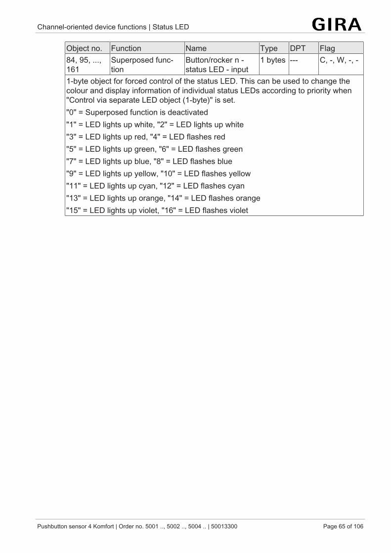
Channel-oriented device functions | Status LED
Pushbutton sensor 4 Komfort | Order no. 5001 .., 5002 .., 5004 .. | 50013300 Page 65 of 106
Object no. Function Name Type DPT Flag84, 95, ...,161
Superposed func-tion
Button/rocker n -status LED - input
1 bytes --- C, -, W, -, -
1-byte object for forced control of the status LED. This can be used to change thecolour and display information of individual status LEDs according to priority when"Control via separate LED object (1-byte)" is set."0" = Superposed function is deactivated"1" = LED lights up white, "2" = LED lights up white"3" = LED lights up red, "4" = LED flashes red"5" = LED lights up green, "6" = LED flashes green"7" = LED lights up blue, "8" = LED flashes blue"9" = LED lights up yellow, "10" = LED flashes yellow"11" = LED lights up cyan, "12" = LED flashes cyan"13" = LED lights up orange, "14" = LED flashes orange"15" = LED lights up violet, "16" = LED flashes violet
Channel-independent device functions |
Pushbutton sensor 4 Komfort | Order no. 5001 .., 5002 .., 5004 .. | 50013300 Page 66 of 106
9 Channel-independent device functionsThe following subchapters provide a description of the device functions. Eachsubchapter consists of the following sections:
– Functional description– Table of parameters– Object list
Functional description
The functional description explains the function and provides helpful tips on projectdesign and usage of the function. Cross references support you in your search forfurther information.
Table of parameters
The table of parameters lists all parameters associated with the function. Each para-meter is documented in a table as follows.
Name of the parameter Parameter valuesParameter description
Object list
The object list specifies and describes all communication objects associated with thefunction. Each communication object is documented in a table.
Object no. This column contains the object number of the communication object.Function This column contains the function of the communication object.Name This column contains the name of the communication object.Type This column contains the length of the communication object.DPT This column assigns a datapoint type to a communication object. Data-
point types are standardized in order to ensure interoperability of KNXdevices.
Flag This column assigns the communication flags in accordance with theKNX specification.
K flag activates / deactivates the communication of the communication objectL flag enables externally triggered reading of the value from the communica-
tion objectS flag enables externally triggered writing of the value to the communication
objectÜ flag enables transfer of a valueA flag enables updating of an object value in case of feedbackI flag enforces updating of the communication object value when the devices
is switched on (reading at init)
Channel-independent device functions | LED alarm signalling
Pushbutton sensor 4 Komfort | Order no. 5001 .., 5002 .., 5004 .. | 50013300 Page 67 of 106
9.1 LED alarm signallingThe push-button sensor permits signalling of an externally reported alarm via itsstatus LED. The alarm can be triggered, for instance, in case of burglary or firethrough a KNX central alarm unit. The push-button sensor signals an alarm by allstatus LEDs of the push-button sensor flashing synchronously. This alarm indicationcan be separately enabled with the parameter "LED alarm signalling" on the "Gen-eral" parameter page.
When LED alarm signalling is enabled, the ETS displays the "Alarm signalling" com-munication object and further alarm function parameters.
The "Alarm signalling" object is used as an input for activating or deactivating thealarm signal display. The polarity of the object can be selected. When the objectvalue corresponds to the "Alarm" condition, all status LEDs are always flashing redwith a frequency of approx. 2 Hz. If there is an alarm, the behaviour of the status LEDas configured in the ETS for normal operation have no significance. The LEDs adopttheir originally configured behaviour only after the alarm signalling function has beendeactivated. Changes of the state of the LEDs during an alarm - if they are controlledby separate LED objects or if they signal push-button functions - are internally storedand recovered at the end of the alarm.
Regardless of the colour configuration of the status LED in normal operationand with a superposed function, the LEDs always flash red when a displayalarm signal is active.
When a display alarm signal is active, the status LEDs of the push-buttonsensor always flash with the regular brightness ("Brightness of all status LEDs"parameter). The push-button sensor automatically deactivates night reductionas long as alarm signalling is active and updates it when alarm signalling isswitched off and the night reduction object still is at "1"-active.
Apart from the possibility of deactivating an alarm signal via the alarm object, it canalso be deactivated locally by a button-press on the push-button sensor itself. The"Reset alarm signalling by a button actuation?" parameter defines the button re-sponse during an alarm:
– If this parameter is set to "Yes", active alarm signal displaying can be deactiv-ated by a button actuation on the push-button sensor. This button functiondoes not cause the configured function of the pressed button to be executed.Only after then next button-press will the configuration of the button be evalu-ated and a telegram be transmitted to the bus, if applicable.
– If "No" has been selected, alarm signalling can only be deactivated via thealarm signalling object. A button function will always directly execute the con-figured button function.
With the disabling function configured, LED alarm signalling cannot be resetby a disabled button.
Channel-independent device functions | LED alarm signalling
Pushbutton sensor 4 Komfort | Order no. 5001 .., 5002 .., 5004 .. | 50013300 Page 68 of 106
If an alarm signal display can be deactivated by pressing any button, the parameter"Use alarm acknowledge object?" defines whether an additional telegram for acknow-ledging the alarm is to be transmitted to the bus via the separate object "Acknow-ledge alarm message".
Such an acknowledge telegram can, for instance, be sent via a 'listening' group ad-dress to the "Alarm signalling" objects of other push button sensors in order to resetthe alarm status there as well. Attention must be paid during resetting of an alarm tothe selectable polarity of the acknowledgement object.
If the setting is "Alarm when OFF and alarm reset when ON", the bus mustactively write "0" to the alarm object in order to activate the alarm after a resetor after programming with the ETS.
An active alarm message is not stored so that the alarm indication is generallydeactivated after a device reset or after programming with the ETS.
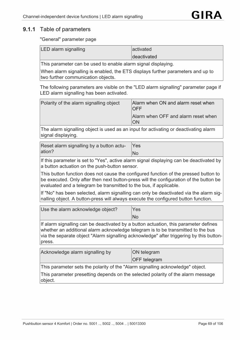
Channel-independent device functions | LED alarm signalling
Pushbutton sensor 4 Komfort | Order no. 5001 .., 5002 .., 5004 .. | 50013300 Page 69 of 106
9.1.1 Table of parameters"General" parameter page
LED alarm signalling activateddeactivated
This parameter can be used to enable alarm signal displaying.When alarm signalling is enabled, the ETS displays further parameters and up totwo further communication objects.
The following parameters are visible on the "LED alarm signalling" parameter page ifLED alarm signalling has been activated.
Polarity of the alarm signalling object Alarm when ON and alarm reset whenOFFAlarm when OFF and alarm reset whenON
The alarm signalling object is used as an input for activating or deactivating alarmsignal displaying.
Reset alarm signalling by a button actu-ation?
YesNo
If this parameter is set to "Yes", active alarm signal displaying can be deactivated bya button actuation on the push-button sensor.This button function does not cause the configured function of the pressed button tobe executed. Only after then next button-press will the configuration of the button beevaluated and a telegram be transmitted to the bus, if applicable.If "No" has been selected, alarm signalling can only be deactivated via the alarm sig-nalling object. A button-press will always execute the configured button function.
Use the alarm acknowledge object? YesNo
If alarm signalling can be deactivated by a button actuation, this parameter defineswhether an additional alarm acknowledge telegram is to be transmitted to the busvia the separate object "Alarm signalling acknowledge" after triggering by this button-press.
Acknowledge alarm signalling by ON telegramOFF telegram
This parameter sets the polarity of the "Alarm signalling acknowledge" object.This parameter presetting depends on the selected polarity of the alarm messageobject.
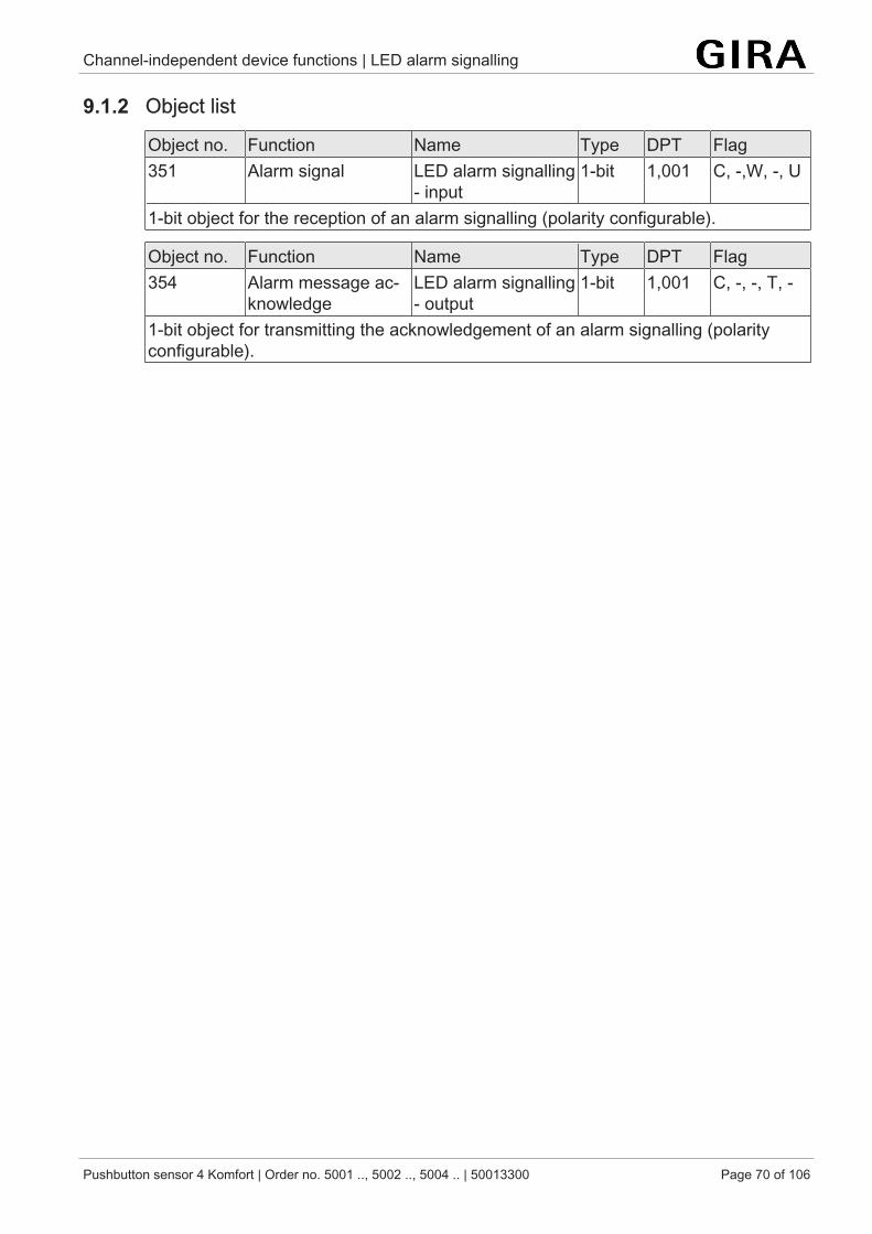
Channel-independent device functions | LED alarm signalling
Pushbutton sensor 4 Komfort | Order no. 5001 .., 5002 .., 5004 .. | 50013300 Page 70 of 106
9.1.2 Object list
Object no. Function Name Type DPT Flag351 Alarm signal LED alarm signalling
- input1-bit 1,001 C, -,W, -, U
1-bit object for the reception of an alarm signalling (polarity configurable).
Object no. Function Name Type DPT Flag354 Alarm message ac-
knowledgeLED alarm signalling- output
1-bit 1,001 C, -, -, T, -
1-bit object for transmitting the acknowledgement of an alarm signalling (polarityconfigurable).
Channel-independent device functions | LED orientation lighting
Pushbutton sensor 4 Komfort | Order no. 5001 .., 5002 .., 5004 .. | 50013300 Page 71 of 106
9.2 LED orientation lightingAll status LEDs of the push-button sensor can be used as orientation lights if neces-sary. The colour of the orientation light can be freely selected from the colour rangeavailable for the status LED. You can also set the brightness at which the status LEDwill light up when orientation light is switched on. When the LED orientation light ison, all status LEDs of the push-button sensor will always light up in the set colour andbrightness. With LED night reduction activated, the corresponding parameter pagecan be used to configure a separate brightness for the orientation light during nightreductionLED night reduction.
The LED orientation light is activated on the "General" parameter page and can sub-sequently be configured on the "LED orientation lighting" parameter page.
For orientation, the status LEDs can be:– switched on continuously,– switched on via an object, or– switched on for a set period of time after pressing a button.
In accordance with the available selection options, random levels can be con-figured for the regular brightness and for the brightness with activated LED ori-entation lighting in the ETS. It is advisable to set the brightness value for LEDorientation lighting to a lower level than regular brightness.
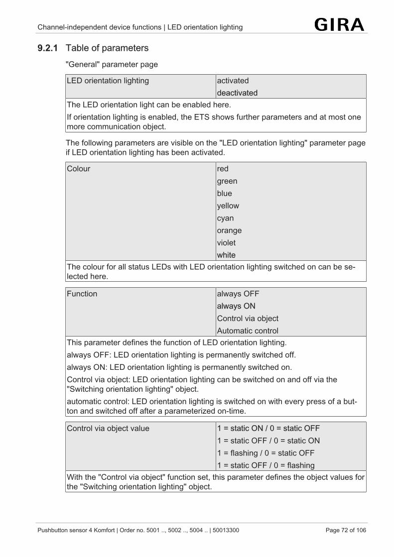
Channel-independent device functions | LED orientation lighting
Pushbutton sensor 4 Komfort | Order no. 5001 .., 5002 .., 5004 .. | 50013300 Page 72 of 106
9.2.1 Table of parameters"General" parameter page
LED orientation lighting activateddeactivated
The LED orientation light can be enabled here.If orientation lighting is enabled, the ETS shows further parameters and at most onemore communication object.
The following parameters are visible on the "LED orientation lighting" parameter pageif LED orientation lighting has been activated.
Colour redgreenblueyellowcyanorangevioletwhite
The colour for all status LEDs with LED orientation lighting switched on can be se-lected here.
Function always OFFalways ONControl via objectAutomatic control
This parameter defines the function of LED orientation lighting.always OFF: LED orientation lighting is permanently switched off.always ON: LED orientation lighting is permanently switched on.Control via object: LED orientation lighting can be switched on and off via the"Switching orientation lighting" object.automatic control: LED orientation lighting is switched on with every press of a but-ton and switched off after a parameterized on-time.
Control via object value 1 = static ON / 0 = static OFF1 = static OFF / 0 = static ON1 = flashing / 0 = static OFF1 = static OFF / 0 = flashing
With the "Control via object" function set, this parameter defines the object values forthe "Switching orientation lighting" object.
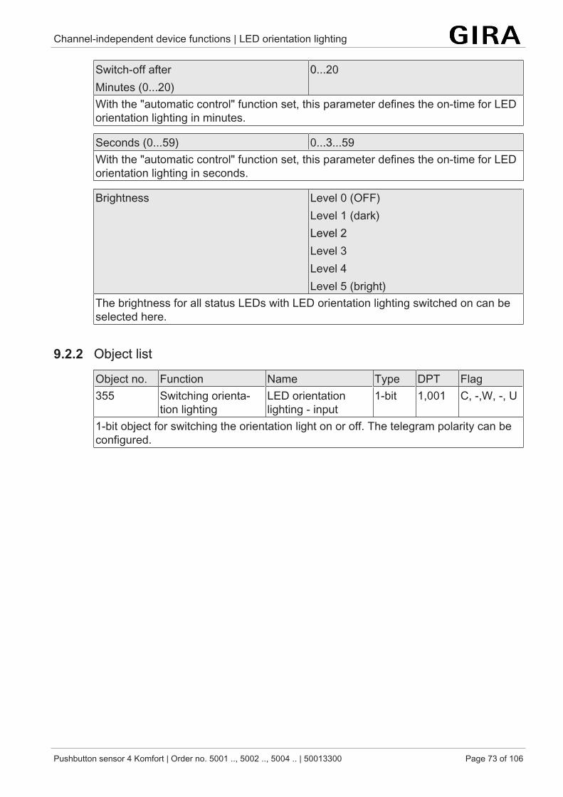
Channel-independent device functions | LED orientation lighting
Pushbutton sensor 4 Komfort | Order no. 5001 .., 5002 .., 5004 .. | 50013300 Page 73 of 106
Switch-off afterMinutes (0...20)
0...20
With the "automatic control" function set, this parameter defines the on-time for LEDorientation lighting in minutes.
Seconds (0...59) 0...3...59With the "automatic control" function set, this parameter defines the on-time for LEDorientation lighting in seconds.
Brightness Level 0 (OFF)Level 1 (dark)Level 2Level 3Level 4Level 5 (bright)
The brightness for all status LEDs with LED orientation lighting switched on can beselected here.
9.2.2 Object list
Object no. Function Name Type DPT Flag355 Switching orienta-
tion lightingLED orientationlighting - input
1-bit 1,001 C, -,W, -, U
1-bit object for switching the orientation light on or off. The telegram polarity can beconfigured.
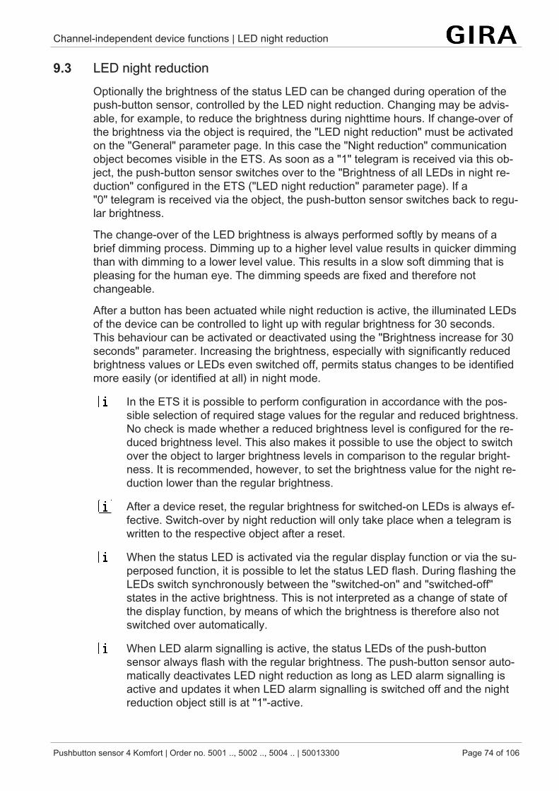
Channel-independent device functions | LED night reduction
Pushbutton sensor 4 Komfort | Order no. 5001 .., 5002 .., 5004 .. | 50013300 Page 74 of 106
9.3 LED night reductionOptionally the brightness of the status LED can be changed during operation of thepush-button sensor, controlled by the LED night reduction. Changing may be advis-able, for example, to reduce the brightness during nighttime hours. If change-over ofthe brightness via the object is required, the "LED night reduction" must be activatedon the "General" parameter page. In this case the "Night reduction" communicationobject becomes visible in the ETS. As soon as a "1" telegram is received via this ob-ject, the push-button sensor switches over to the "Brightness of all LEDs in night re-duction" configured in the ETS ("LED night reduction" parameter page). If a"0" telegram is received via the object, the push-button sensor switches back to regu-lar brightness.
The change-over of the LED brightness is always performed softly by means of abrief dimming process. Dimming up to a higher level value results in quicker dimmingthan with dimming to a lower level value. This results in a slow soft dimming that ispleasing for the human eye. The dimming speeds are fixed and therefore notchangeable.
After a button has been actuated while night reduction is active, the illuminated LEDsof the device can be controlled to light up with regular brightness for 30 seconds.This behaviour can be activated or deactivated using the "Brightness increase for 30seconds" parameter. Increasing the brightness, especially with significantly reducedbrightness values or LEDs even switched off, permits status changes to be identifiedmore easily (or identified at all) in night mode.
In the ETS it is possible to perform configuration in accordance with the pos-sible selection of required stage values for the regular and reduced brightness.No check is made whether a reduced brightness level is configured for the re-duced brightness level. This also makes it possible to use the object to switchover the object to larger brightness levels in comparison to the regular bright-ness. It is recommended, however, to set the brightness value for the night re-duction lower than the regular brightness.
After a device reset, the regular brightness for switched-on LEDs is always ef-fective. Switch-over by night reduction will only take place when a telegram iswritten to the respective object after a reset.
When the status LED is activated via the regular display function or via the su-perposed function, it is possible to let the status LED flash. During flashing theLEDs switch synchronously between the "switched-on" and "switched-off"states in the active brightness. This is not interpreted as a change of state ofthe display function, by means of which the brightness is therefore also notswitched over automatically.
When LED alarm signalling is active, the status LEDs of the push-buttonsensor always flash with the regular brightness. The push-button sensor auto-matically deactivates LED night reduction as long as LED alarm signalling isactive and updates it when LED alarm signalling is switched off and the nightreduction object still is at "1"-active.
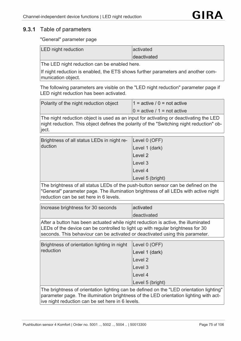
Channel-independent device functions | LED night reduction
Pushbutton sensor 4 Komfort | Order no. 5001 .., 5002 .., 5004 .. | 50013300 Page 75 of 106
9.3.1 Table of parameters"General" parameter page
LED night reduction activateddeactivated
The LED night reduction can be enabled here.If night reduction is enabled, the ETS shows further parameters and another com-munication object.
The following parameters are visible on the "LED night reduction" parameter page ifLED night reduction has been activated.
Polarity of the night reduction object 1 = active / 0 = not active0 = active / 1 = not active
The night reduction object is used as an input for activating or deactivating the LEDnight reduction. This object defines the polarity of the "Switching night reduction" ob-ject.
Brightness of all status LEDs in night re-duction
Level 0 (OFF)Level 1 (dark)Level 2Level 3Level 4Level 5 (bright)
The brightness of all status LEDs of the push-button sensor can be defined on the"General" parameter page. The illumination brightness of all LEDs with active nightreduction can be set here in 6 levels.
Increase brightness for 30 seconds activateddeactivated
After a button has been actuated while night reduction is active, the illuminatedLEDs of the device can be controlled to light up with regular brightness for 30seconds. This behaviour can be activated or deactivated using this parameter.
Brightness of orientation lighting in nightreduction
Level 0 (OFF)Level 1 (dark)Level 2Level 3Level 4Level 5 (bright)
The brightness of orientation lighting can be defined on the "LED orientation lighting"parameter page. The illumination brightness of the LED orientation lighting with act-ive night reduction can be set here in 6 levels.
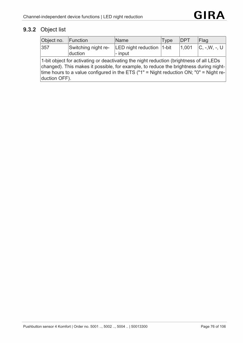
Channel-independent device functions | LED night reduction
Pushbutton sensor 4 Komfort | Order no. 5001 .., 5002 .., 5004 .. | 50013300 Page 76 of 106
9.3.2 Object list
Object no. Function Name Type DPT Flag357 Switching night re-
ductionLED night reduction- input
1-bit 1,001 C, -,W, -, U
1-bit object for activating or deactivating the night reduction (brightness of all LEDschanged). This makes it possible, for example, to reduce the brightness during night-time hours to a value configured in the ETS ("1" = Night reduction ON; "0" = Night re-duction OFF).
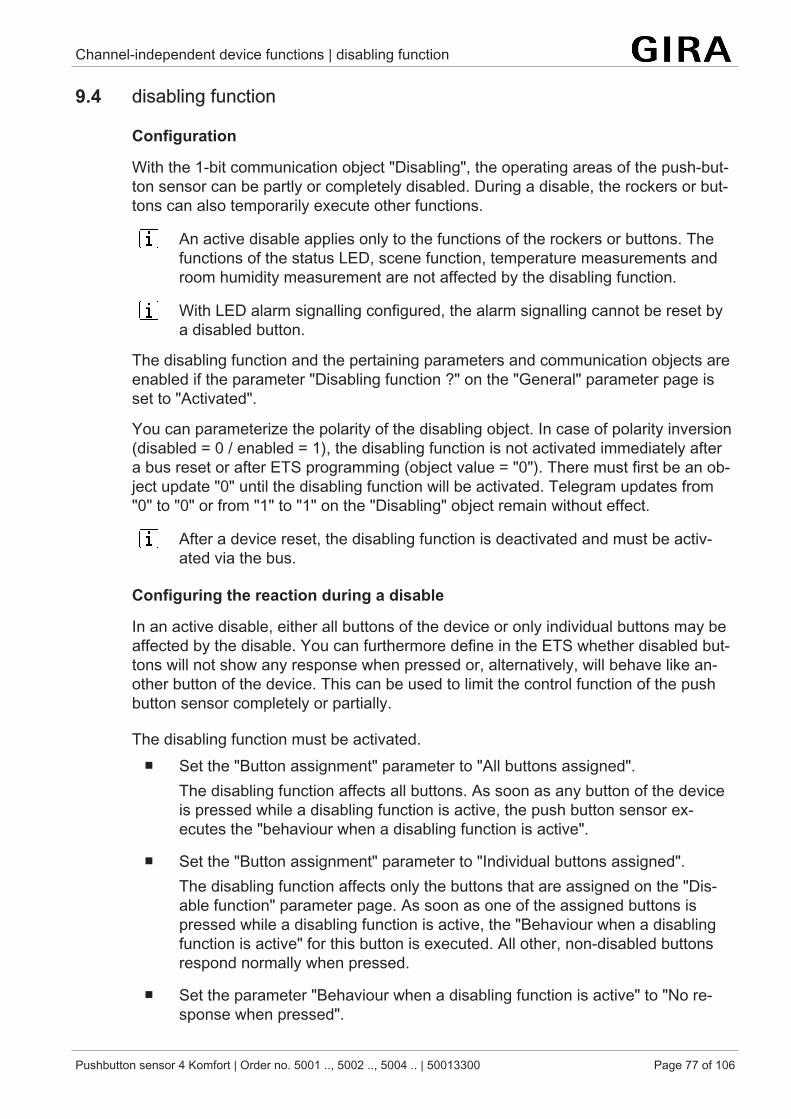
Channel-independent device functions | disabling function
Pushbutton sensor 4 Komfort | Order no. 5001 .., 5002 .., 5004 .. | 50013300 Page 77 of 106
9.4 disabling function
Configuration
With the 1-bit communication object "Disabling", the operating areas of the push-but-ton sensor can be partly or completely disabled. During a disable, the rockers or but-tons can also temporarily execute other functions.
An active disable applies only to the functions of the rockers or buttons. Thefunctions of the status LED, scene function, temperature measurements androom humidity measurement are not affected by the disabling function.
With LED alarm signalling configured, the alarm signalling cannot be reset bya disabled button.
The disabling function and the pertaining parameters and communication objects areenabled if the parameter "Disabling function ?" on the "General" parameter page isset to "Activated".
You can parameterize the polarity of the disabling object. In case of polarity inversion(disabled = 0 / enabled = 1), the disabling function is not activated immediately aftera bus reset or after ETS programming (object value = "0"). There must first be an ob-ject update "0" until the disabling function will be activated. Telegram updates from"0" to "0" or from "1" to "1" on the "Disabling" object remain without effect.
After a device reset, the disabling function is deactivated and must be activ-ated via the bus.
Configuring the reaction during a disable
In an active disable, either all buttons of the device or only individual buttons may beaffected by the disable. You can furthermore define in the ETS whether disabled but-tons will not show any response when pressed or, alternatively, will behave like an-other button of the device. This can be used to limit the control function of the pushbutton sensor completely or partially.
The disabling function must be activated.■ Set the "Button assignment" parameter to "All buttons assigned".
The disabling function affects all buttons. As soon as any button of the deviceis pressed while a disabling function is active, the push button sensor ex-ecutes the "behaviour when a disabling function is active".
■ Set the "Button assignment" parameter to "Individual buttons assigned".The disabling function affects only the buttons that are assigned on the "Dis-able function" parameter page. As soon as one of the assigned buttons ispressed while a disabling function is active, the "Behaviour when a disablingfunction is active" for this button is executed. All other, non-disabled buttonsrespond normally when pressed.
■ Set the parameter "Behaviour when a disabling function is active" to "No re-sponse when pressed".
Channel-independent device functions | disabling function
Pushbutton sensor 4 Komfort | Order no. 5001 .., 5002 .., 5004 .. | 50013300 Page 78 of 106
The disabled buttons do not respond when pressed. The status LEDs of thedisabled buttons remain off if the display function is configured to "Button-press display" or "Telegram acknowledgement".
■ Set the parameter "Behaviour when a disabling function is active" to "No re-sponse when pressed like...". Also configure the parameters "All assigned rightbuttons behave like" and "All assigned left buttons behave like" to the requiredbutton number or disabling function as a reference button.All buttons assigned to the disabling function behave as defined in the para-meters for the two specified reference buttons of the push button sensor. Dif-ferent or identical reference buttons can be configured separately for all theleft and right operating buttons. The two "virtual" disabling functions of thepush button sensor can also be configured as a reference button.The telegrams are transmitted to the bus via the communication objects of thespecified reference buttons. The status LEDs of the reference buttons are con-trolled according to their function. The status LEDs of the disabled buttons re-main off if the display function is configured to "Button-press display" or "Tele-gram acknowledgement".
If a button evaluation is taking place at the time of activation / deactivation of adisabling function, this function is aborted immediately and with it also the per-taining button function. It is first necessary to release all buttons before a newbutton function can be executed if so permitted by the state of disabling.
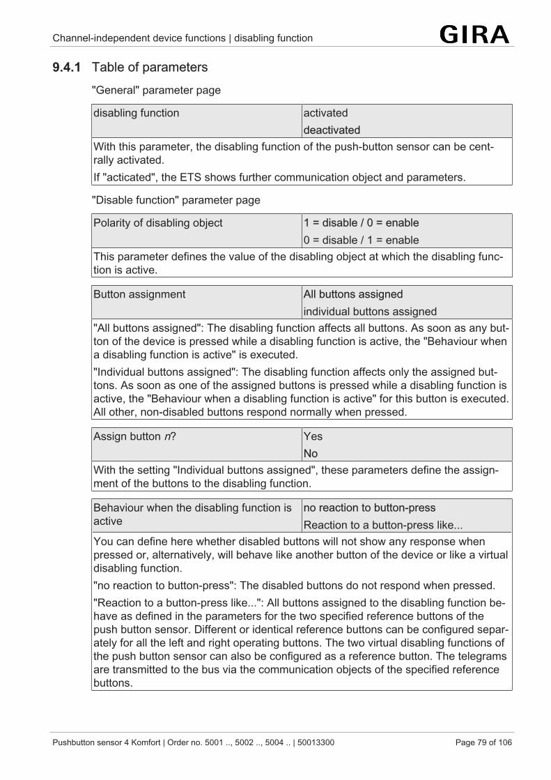
Channel-independent device functions | disabling function
Pushbutton sensor 4 Komfort | Order no. 5001 .., 5002 .., 5004 .. | 50013300 Page 79 of 106
9.4.1 Table of parameters"General" parameter page
disabling function activateddeactivated
With this parameter, the disabling function of the push-button sensor can be cent-rally activated.If "acticated", the ETS shows further communication object and parameters.
"Disable function" parameter page
Polarity of disabling object 1 = disable / 0 = enable0 = disable / 1 = enable
This parameter defines the value of the disabling object at which the disabling func-tion is active.
Button assignment All buttons assignedindividual buttons assigned
"All buttons assigned": The disabling function affects all buttons. As soon as any but-ton of the device is pressed while a disabling function is active, the "Behaviour whena disabling function is active" is executed."Individual buttons assigned": The disabling function affects only the assigned but-tons. As soon as one of the assigned buttons is pressed while a disabling function isactive, the "Behaviour when a disabling function is active" for this button is executed.All other, non-disabled buttons respond normally when pressed.
Assign button n? YesNo
With the setting "Individual buttons assigned", these parameters define the assign-ment of the buttons to the disabling function.
Behaviour when the disabling function isactive
no reaction to button-pressReaction to a button-press like...
You can define here whether disabled buttons will not show any response whenpressed or, alternatively, will behave like another button of the device or like a virtualdisabling function."no reaction to button-press": The disabled buttons do not respond when pressed."Reaction to a button-press like...": All buttons assigned to the disabling function be-have as defined in the parameters for the two specified reference buttons of thepush button sensor. Different or identical reference buttons can be configured separ-ately for all the left and right operating buttons. The two virtual disabling functions ofthe push button sensor can also be configured as a reference button. The telegramsare transmitted to the bus via the communication objects of the specified referencebuttons.
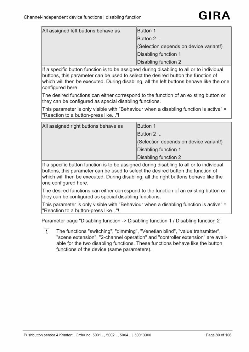
Channel-independent device functions | disabling function
Pushbutton sensor 4 Komfort | Order no. 5001 .., 5002 .., 5004 .. | 50013300 Page 80 of 106
All assigned left buttons behave as Button 1Button 2 ...(Selection depends on device variant!)Disabling function 1Disabling function 2
If a specific button function is to be assigned during disabling to all or to individualbuttons, this parameter can be used to select the desired button the function ofwhich will then be executed. During disabling, all the left buttons behave like the oneconfigured here.The desired functions can either correspond to the function of an existing button orthey can be configured as special disabling functions.This parameter is only visible with "Behaviour when a disabling function is active" ="Reaction to a button-press like..."!
All assigned right buttons behave as Button 1Button 2 ...(Selection depends on device variant!)Disabling function 1Disabling function 2
If a specific button function is to be assigned during disabling to all or to individualbuttons, this parameter can be used to select the desired button the function ofwhich will then be executed. During disabling, all the right buttons behave like theone configured here.The desired functions can either correspond to the function of an existing button orthey can be configured as special disabling functions.This parameter is only visible with "Behaviour when a disabling function is active" ="Reaction to a button-press like..."!
Parameter page "Disabling function -> Disabling function 1 / Disabling function 2"
The functions "switching", "dimming", "Venetian blind", "value transmitter","scene extension", "2-channel operation" and "controller extension" are avail-able for the two disabling functions. These functions behave like the buttonfunctions of the device (same parameters).
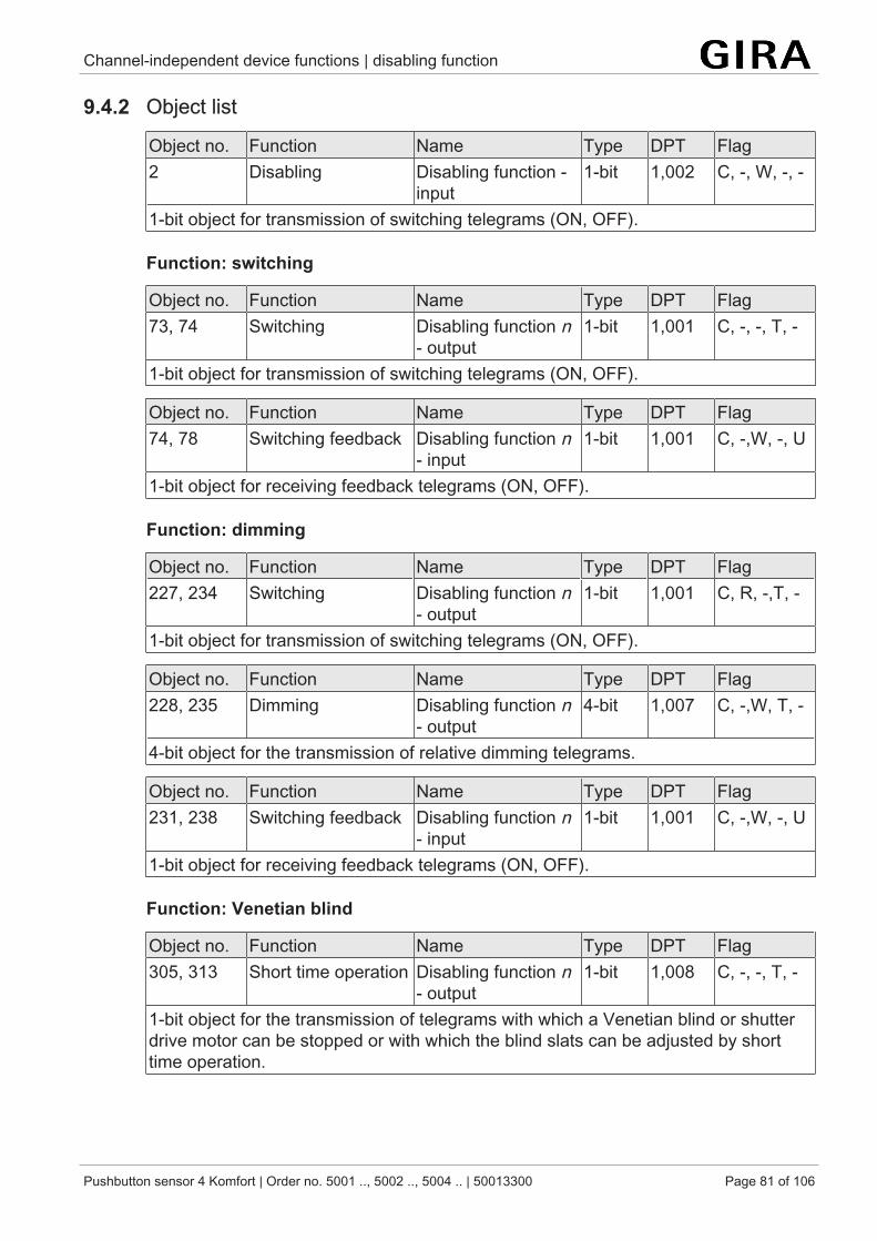
Channel-independent device functions | disabling function
Pushbutton sensor 4 Komfort | Order no. 5001 .., 5002 .., 5004 .. | 50013300 Page 81 of 106
9.4.2 Object list
Object no. Function Name Type DPT Flag2 Disabling Disabling function -
input1-bit 1,002 C, -, W, -, -
1-bit object for transmission of switching telegrams (ON, OFF).
Function: switching
Object no. Function Name Type DPT Flag73, 74 Switching Disabling function n
- output1-bit 1,001 C, -, -, T, -
1-bit object for transmission of switching telegrams (ON, OFF).
Object no. Function Name Type DPT Flag74, 78 Switching feedback Disabling function n
- input1-bit 1,001 C, -,W, -, U
1-bit object for receiving feedback telegrams (ON, OFF).
Function: dimming
Object no. Function Name Type DPT Flag227, 234 Switching Disabling function n
- output1-bit 1,001 C, R, -,T, -
1-bit object for transmission of switching telegrams (ON, OFF).
Object no. Function Name Type DPT Flag228, 235 Dimming Disabling function n
- output4-bit 1,007 C, -,W, T, -
4-bit object for the transmission of relative dimming telegrams.
Object no. Function Name Type DPT Flag231, 238 Switching feedback Disabling function n
- input1-bit 1,001 C, -,W, -, U
1-bit object for receiving feedback telegrams (ON, OFF).
Function: Venetian blind
Object no. Function Name Type DPT Flag305, 313 Short time operation Disabling function n
- output1-bit 1,008 C, -, -, T, -
1-bit object for the transmission of telegrams with which a Venetian blind or shutterdrive motor can be stopped or with which the blind slats can be adjusted by shorttime operation.
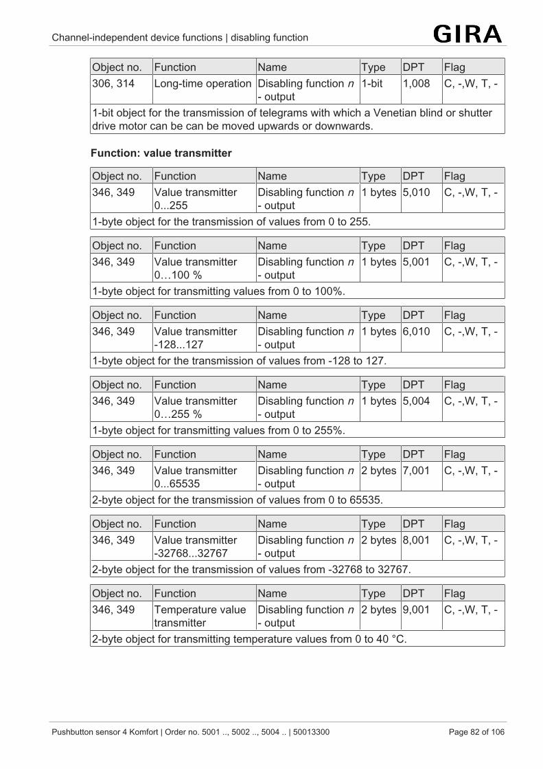
Channel-independent device functions | disabling function
Pushbutton sensor 4 Komfort | Order no. 5001 .., 5002 .., 5004 .. | 50013300 Page 82 of 106
Object no. Function Name Type DPT Flag306, 314 Long-time operation Disabling function n
- output1-bit 1,008 C, -,W, T, -
1-bit object for the transmission of telegrams with which a Venetian blind or shutterdrive motor can be can be moved upwards or downwards.
Function: value transmitter
Object no. Function Name Type DPT Flag346, 349 Value transmitter
0...255Disabling function n- output
1 bytes 5,010 C, -,W, T, -
1-byte object for the transmission of values from 0 to 255.
Object no. Function Name Type DPT Flag346, 349 Value transmitter
0…100 %Disabling function n- output
1 bytes 5,001 C, -,W, T, -
1-byte object for transmitting values from 0 to 100%.
Object no. Function Name Type DPT Flag346, 349 Value transmitter
-128...127Disabling function n- output
1 bytes 6,010 C, -,W, T, -
1-byte object for the transmission of values from -128 to 127.
Object no. Function Name Type DPT Flag346, 349 Value transmitter
0…255 %Disabling function n- output
1 bytes 5,004 C, -,W, T, -
1-byte object for transmitting values from 0 to 255%.
Object no. Function Name Type DPT Flag346, 349 Value transmitter
0...65535Disabling function n- output
2 bytes 7,001 C, -,W, T, -
2-byte object for the transmission of values from 0 to 65535.
Object no. Function Name Type DPT Flag346, 349 Value transmitter
-32768...32767Disabling function n- output
2 bytes 8,001 C, -,W, T, -
2-byte object for the transmission of values from -32768 to 32767.
Object no. Function Name Type DPT Flag346, 349 Temperature value
transmitterDisabling function n- output
2 bytes 9,001 C, -,W, T, -
2-byte object for transmitting temperature values from 0 to 40 °C.
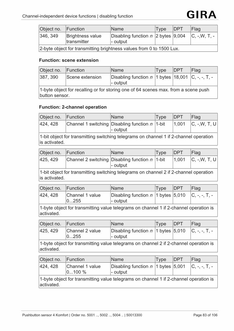
Channel-independent device functions | disabling function
Pushbutton sensor 4 Komfort | Order no. 5001 .., 5002 .., 5004 .. | 50013300 Page 83 of 106
Object no. Function Name Type DPT Flag346, 349 Brightness value
transmitterDisabling function n- output
2 bytes 9,004 C, -,W, T, -
2-byte object for transmitting brightness values from 0 to 1500 Lux.
Function: scene extension
Object no. Function Name Type DPT Flag387, 390 Scene extension Disabling function n
- output1 bytes 18,001 C, -, -, T, -
1-byte object for recalling or for storing one of 64 scenes max. from a scene pushbutton sensor.
Function: 2-channel operation
Object no. Function Name Type DPT Flag424, 428 Channel 1 switching Disabling function n
- output1-bit 1,001 C, -,W, T, U
1-bit object for transmitting switching telegrams on channel 1 if 2-channel operationis activated.
Object no. Function Name Type DPT Flag425, 429 Channel 2 switching Disabling function n
- output1-bit 1,001 C, -,W, T, U
1-bit object for transmitting switching telegrams on channel 2 if 2-channel operationis activated.
Object no. Function Name Type DPT Flag424, 428 Channel 1 value
0...255Disabling function n- output
1 bytes 5,010 C, -, -, T, -
1-byte object for transmitting value telegrams on channel 1 if 2-channel operation isactivated.
Object no. Function Name Type DPT Flag425, 429 Channel 2 value
0...255Disabling function n- output
1 bytes 5,010 C, -, -, T, -
1-byte object for transmitting value telegrams on channel 2 if 2-channel operation isactivated.
Object no. Function Name Type DPT Flag424, 428 Channel 1 value
0...100 %Disabling function n- output
1 bytes 5,001 C, -, -, T, -
1-byte object for transmitting value telegrams on channel 1 if 2-channel operation isactivated.
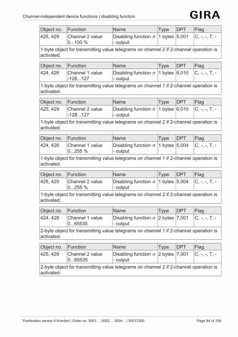
Channel-independent device functions | disabling function
Pushbutton sensor 4 Komfort | Order no. 5001 .., 5002 .., 5004 .. | 50013300 Page 84 of 106
Object no. Function Name Type DPT Flag425, 429 Channel 2 value
0...100 %Disabling function n- output
1 bytes 5,001 C, -, -, T, -
1-byte object for transmitting value telegrams on channel 2 if 2-channel operation isactivated.
Object no. Function Name Type DPT Flag424, 428 Channel 1 value
-128...127Disabling function n- output
1 bytes 6,010 C, -, -, T, -
1-byte object for transmitting value telegrams on channel 1 if 2-channel operation isactivated.
Object no. Function Name Type DPT Flag425, 429 Channel 2 value
-128...127Disabling function n- output
1 bytes 6,010 C, -, -, T, -
1-byte object for transmitting value telegrams on channel 2 if 2-channel operation isactivated.
Object no. Function Name Type DPT Flag424, 428 Channel 1 value
0...255 %Disabling function n- output
1 bytes 5,004 C, -, -, T, -
1-byte object for transmitting value telegrams on channel 1 if 2-channel operation isactivated.
Object no. Function Name Type DPT Flag425, 429 Channel 2 value
0...255 %Disabling function n- output
1 bytes 5,004 C, -, -, T, -
1-byte object for transmitting value telegrams on channel 2 if 2-channel operation isactivated.
Object no. Function Name Type DPT Flag424, 428 Channel 1 value
0...65535Disabling function n- output
2 bytes 7,001 C, -, -, T, -
2-byte object for transmitting value telegrams on channel 1 if 2-channel operation isactivated.
Object no. Function Name Type DPT Flag425, 429 Channel 2 value
0...65535Disabling function n- output
2 bytes 7,001 C, -, -, T, -
2-byte object for transmitting value telegrams on channel 2 if 2-channel operation isactivated.

Channel-independent device functions | disabling function
Pushbutton sensor 4 Komfort | Order no. 5001 .., 5002 .., 5004 .. | 50013300 Page 85 of 106
Object no. Function Name Type DPT Flag424, 428 Channel 1 value
-32768...32767Disabling function n- output
2 bytes 8,001 C, -, -, T, -
2-byte object for transmitting value telegrams on channel 1 if 2-channel operation isactivated.
Object no. Function Name Type DPT Flag425, 429 Channel 2 value
-32768...32767Disabling function n- output
2 bytes 8,001 C, -, -, T, -
2-byte object for transmitting value telegrams on channel 2 if 2-channel operation isactivated.
Object no. Function Name Type DPT Flag424, 428 Channel 1 temperat-
ure valueDisabling function n- output
2 bytes 9,001 C, -, -, T, -
2-byte object for transmitting temperature values on channel 1 if 2-channel operationis activated.
Object no. Function Name Type DPT Flag425, 429 Channel 2 temperat-
ure valueDisabling function n- output
2 bytes 9,001 C, -, -, T, -
2-byte object for transmitting temperature values on channel 2 if 2-channel operationis activated.
Object no. Function Name Type DPT Flag424, 428 Channel 1 bright-
ness valueDisabling function n- output
2 bytes 9,004 C, -, -, T, -
2-byte object for transmitting brightness values on channel 1 if 2-channel operationis activated.
Object no. Function Name Type DPT Flag425, 429 Channel 2 bright-
ness valueDisabling function n- output
2 bytes 9,004 C, -, -, T, -
2-byte object for transmitting brightness values on channel 2 if 2-channel operationis activated.
Object no. Function Name Type DPT Flag424, 428 Channel 1 scene
(external) 1…64Disabling function n- output
1 bytes 18,001 C, -, -, T, -
1-byte object for transmitting scene values on channel 1 if 2-channel operation is ac-tivated.
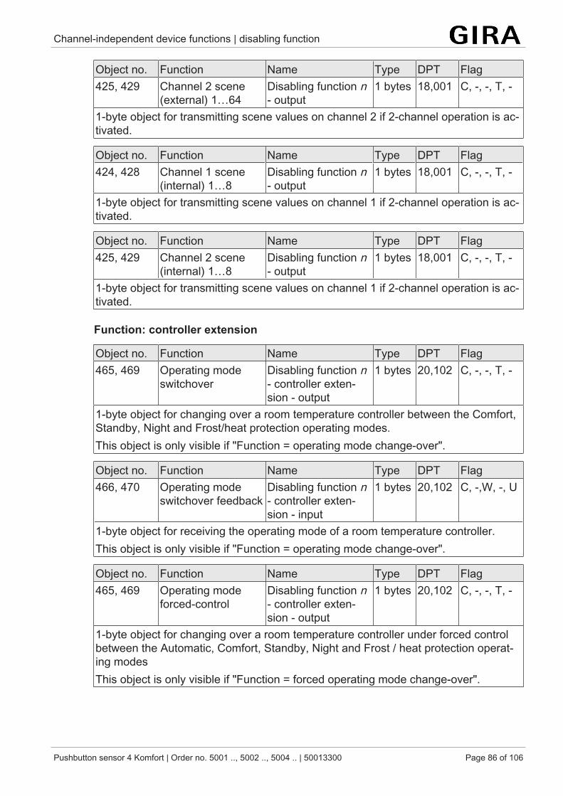
Channel-independent device functions | disabling function
Pushbutton sensor 4 Komfort | Order no. 5001 .., 5002 .., 5004 .. | 50013300 Page 86 of 106
Object no. Function Name Type DPT Flag425, 429 Channel 2 scene
(external) 1…64Disabling function n- output
1 bytes 18,001 C, -, -, T, -
1-byte object for transmitting scene values on channel 2 if 2-channel operation is ac-tivated.
Object no. Function Name Type DPT Flag424, 428 Channel 1 scene
(internal) 1…8Disabling function n- output
1 bytes 18,001 C, -, -, T, -
1-byte object for transmitting scene values on channel 1 if 2-channel operation is ac-tivated.
Object no. Function Name Type DPT Flag425, 429 Channel 2 scene
(internal) 1…8Disabling function n- output
1 bytes 18,001 C, -, -, T, -
1-byte object for transmitting scene values on channel 1 if 2-channel operation is ac-tivated.
Function: controller extension
Object no. Function Name Type DPT Flag465, 469 Operating mode
switchoverDisabling function n- controller exten-sion - output
1 bytes 20,102 C, -, -, T, -
1-byte object for changing over a room temperature controller between the Comfort,Standby, Night and Frost/heat protection operating modes.This object is only visible if "Function = operating mode change-over".
Object no. Function Name Type DPT Flag466, 470 Operating mode
switchover feedbackDisabling function n- controller exten-sion - input
1 bytes 20,102 C, -,W, -, U
1-byte object for receiving the operating mode of a room temperature controller.This object is only visible if "Function = operating mode change-over".
Object no. Function Name Type DPT Flag465, 469 Operating mode
forced-controlDisabling function n- controller exten-sion - output
1 bytes 20,102 C, -, -, T, -
1-byte object for changing over a room temperature controller under forced controlbetween the Automatic, Comfort, Standby, Night and Frost / heat protection operat-ing modesThis object is only visible if "Function = forced operating mode change-over".
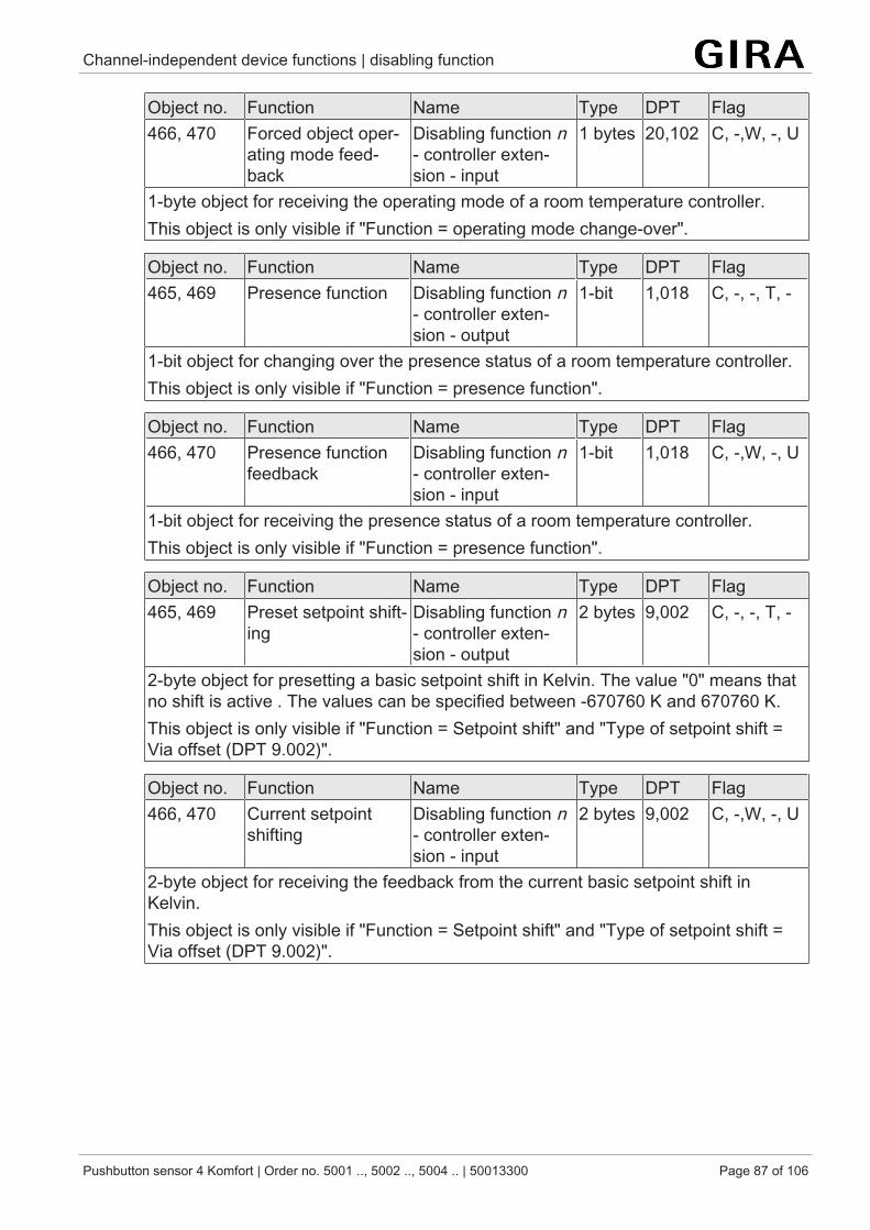
Channel-independent device functions | disabling function
Pushbutton sensor 4 Komfort | Order no. 5001 .., 5002 .., 5004 .. | 50013300 Page 87 of 106
Object no. Function Name Type DPT Flag466, 470 Forced object oper-
ating mode feed-back
Disabling function n- controller exten-sion - input
1 bytes 20,102 C, -,W, -, U
1-byte object for receiving the operating mode of a room temperature controller.This object is only visible if "Function = operating mode change-over".
Object no. Function Name Type DPT Flag465, 469 Presence function Disabling function n
- controller exten-sion - output
1-bit 1,018 C, -, -, T, -
1-bit object for changing over the presence status of a room temperature controller.This object is only visible if "Function = presence function".
Object no. Function Name Type DPT Flag466, 470 Presence function
feedbackDisabling function n- controller exten-sion - input
1-bit 1,018 C, -,W, -, U
1-bit object for receiving the presence status of a room temperature controller.This object is only visible if "Function = presence function".
Object no. Function Name Type DPT Flag465, 469 Preset setpoint shift-
ingDisabling function n- controller exten-sion - output
2 bytes 9,002 C, -, -, T, -
2-byte object for presetting a basic setpoint shift in Kelvin. The value "0" means thatno shift is active . The values can be specified between -670760 K and 670760 K.This object is only visible if "Function = Setpoint shift" and "Type of setpoint shift =Via offset (DPT 9.002)".
Object no. Function Name Type DPT Flag466, 470 Current setpoint
shiftingDisabling function n- controller exten-sion - input
2 bytes 9,002 C, -,W, -, U
2-byte object for receiving the feedback from the current basic setpoint shift inKelvin.This object is only visible if "Function = Setpoint shift" and "Type of setpoint shift =Via offset (DPT 9.002)".
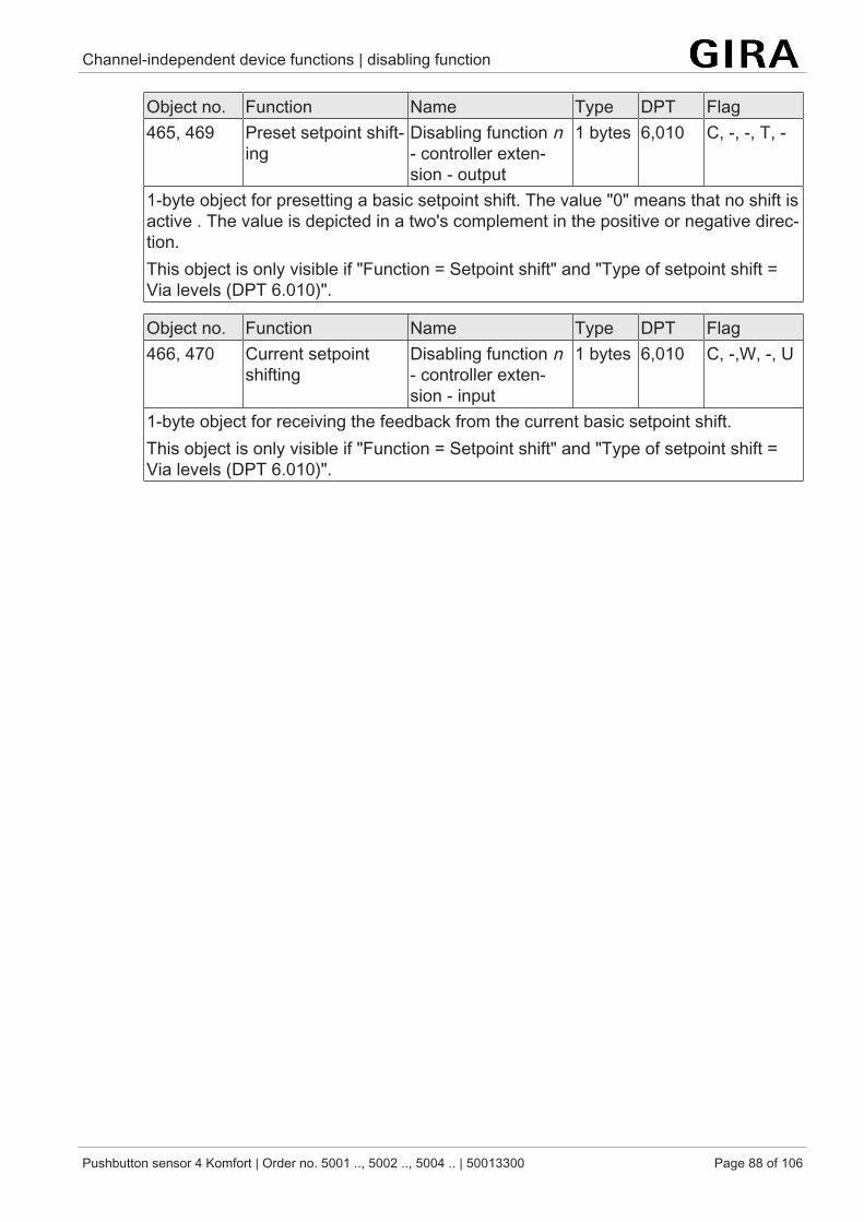
Channel-independent device functions | disabling function
Pushbutton sensor 4 Komfort | Order no. 5001 .., 5002 .., 5004 .. | 50013300 Page 88 of 106
Object no. Function Name Type DPT Flag465, 469 Preset setpoint shift-
ingDisabling function n- controller exten-sion - output
1 bytes 6,010 C, -, -, T, -
1-byte object for presetting a basic setpoint shift. The value "0" means that no shift isactive . The value is depicted in a two's complement in the positive or negative direc-tion.This object is only visible if "Function = Setpoint shift" and "Type of setpoint shift =Via levels (DPT 6.010)".
Object no. Function Name Type DPT Flag466, 470 Current setpoint
shiftingDisabling function n- controller exten-sion - input
1 bytes 6,010 C, -,W, -, U
1-byte object for receiving the feedback from the current basic setpoint shift.This object is only visible if "Function = Setpoint shift" and "Type of setpoint shift =Via levels (DPT 6.010)".
Channel-independent device functions | Scene function
Pushbutton sensor 4 Komfort | Order no. 5001 .., 5002 .., 5004 .. | 50013300 Page 89 of 106
9.5 Scene function
Scene control
The push-button sensor can be used in two different ways as part of a scene controlsystem:
– Each rocker or button can work as a scene extension. This feature makes itpossible to recall or to store scenes which may be stored in other devices .
– The push-button sensor can independently store up to eight scenes with eightactuator groups. These internal scenes can be recalled or stored by the rock-ers or buttons (internal scene recall) and also by the "extension" communica-tion object.In the following subsections the internal scene function will be dealt with ingreater detail.
Scene definition and scene recall
If the internal scenes are to be used, the "Scene function" parameter on the "Gen-eral" parameter page must be set to "Activated". When the scene function is activ-ated, the ETS automatically shows the "Scene function" parameter page. The match-ing data types for the eight scene outputs must then be selected on the "Scene datatypes" parameter page and adapted to the actuator groups used. The types "Switch-ing", "Value (0 … 255)" or "Value / blind position (0…100%)" can be selected. As arule, Venetian blinds are controlled via two scene outputs. One output controls theblind height and the other one adjusts the slat position.
The ETS sets the corresponding communication objects and the parameters of thescene commands on the following parameter pages "Scene 1" to "Scene 8".
It is possible that the values for the individual scenes preset by the parameters aremodified later on with the storage function (siehe Kapitel "Scene function" } Page90) when the system is in operation. If the application program is then loaded againwith the ETS, these locally adapted values will normally be overwritten by the para-meters. Due to the fact that it may take considerable efforts to readjust the values forall scenes in the system, the parameter "Overwrite scene values during ETS down-load ?" offers the possibility of retaining the scene values stored in operation.
The scene parameters can be set on the parameter page of each individual scene("Scene 1 ... 8"). The setting options are the same for all 8 scenes.
These internal scenes can be recalled directly via the rockers or buttons (function "re-call internal scene") and also by another bus device via the "Extension" communica-tion object. This 1 byte communication object supports the evaluation of up to 64scene numbers. For this reason, it must be specified in ETS which of the externalscene numbers (1 … 64) is to recall the internal scene (1 … 8). If the same scenenumber is listed for several internal scenes, it is always only the first of these scenesthat will be activated (scene with the lowest scene number).
In some situations there may be the requirement that a group of actuators is not con-trolled by all, but only by certain scenes. A classroom, for instance, may require openblinds for the "Welcome" and "Break" scenes, closed blinds in the "PC presentation"
Channel-independent device functions | Scene function
Pushbutton sensor 4 Komfort | Order no. 5001 .., 5002 .., 5004 .. | 50013300 Page 90 of 106
scene and no change in the "Discussion" scene. In this example, the parameter "Per-mit transmission ?" can be set to "No" for the "Discussion" scene. The scene outputis then deactivated during the corresponding scene.
The parameter "Transmit delay" permits entering an individual waiting time for eachscene output. This transmit delay can be used in different situations:
– When the actuators participating in a scene transmit status messages auto-matically or when several scene buttons are used to increase the number ofchannels within the scenes, the recall of a scene may result for a short time inhigh bus loading. The transmit delay helps to reduce the bus load at the timeof scene recall.
– Sometimes, it is desirable that an action is started only after another actionhas ended. This can be for instance the illumination which is to shut off onlyafter the blinds/shutters have been raised.
The transmit delay can be set separately for each scene output. The transmit delaydefines the time delay between the individual telegrams during a scene recall. Thesetting specifies how much time must pass after the first scene telegram before thesecond is transmitted. After transmission of the second scene telegram, the con-figured time must again pass before the third is transmitted. The delay continues asfollows for each additional scene telegram. The transmit delay for the first scene tele-gram starts immediately after the scene has been recalled.
The transmit delay between telegrams can also be deactivated (setting "0"). The tele-grams are then transmitted at the shortest possible time interval. In this case, how-ever, the order of the telegrams transmitted can deviate from the numbering of thescene outputs.
When a new scene recall (also with the same scene number) occurs during acurrent scene recall - even in consideration of the pertaining transmit delays -the scene processing started first will be aborted and the newly receivedscene number will be processed. A running scene is also aborted when ascene is being stored!
During a scene recall - even if delayed - the control surfaces of the push but-ton sensor are normally operational.
Storing scenes
For each output of a scene, the user can define a corresponding scene value in theETS which is then transmitted to the bus during a scene recall. During the ongoingoperation of the system it may be necessary to adapt these preset values and tosave the adapted values in the push-button sensor. This can be ensured by the stor-age function of the scene control.
The value storage function for the corresponding scene number is enabled with theparameter "Permit storing ?" ("Yes") or disabled ("No"). When the storage function isdisabled, the object value of the corresponding output is not sampled during storage.
A scene storage process can be initiated in two different ways:
Channel-independent device functions | Scene function
Pushbutton sensor 4 Komfort | Order no. 5001 .., 5002 .., 5004 .. | 50013300 Page 91 of 106
– by a long press on a rocker or button of a control surface configured as "sceneextension"
– by a storage telegram to the extension object.
During a storage process, the push-button sensor reads the current object values ofthe connected actuators. This is carried out by means of eight read telegrams (Valu-eRead) addressed to the devices in the scene which return their own value (Valu-eResponse) as a reaction to the request. The returned values are received by thepush-button sensor and taken over permanently into the scene memory. Per sceneoutput, the push-button sensor waits one second for a response. If no answer is re-ceived during this time, the value for this scene output remains unchanged and thepush-button sensor scans the next output.
In order to enable the push-button sensor to read the object value of the actuator ad-dressed when a scene is stored, the read flag of the corresponding actuator objectmust be set. This should be done only for one actuator out of an actuator group sothat the value response is unequivocal.
The stored values overwrite those programmed into the push-button sensor with theETS.
The storage process will always be executed completely by the push-button sensorand cannot not be aborted before it has ended. Recalling scenes in the course of astorage process is not possible, the operating areas of the pushbutton sensor re-maining nevertheless normally operational.
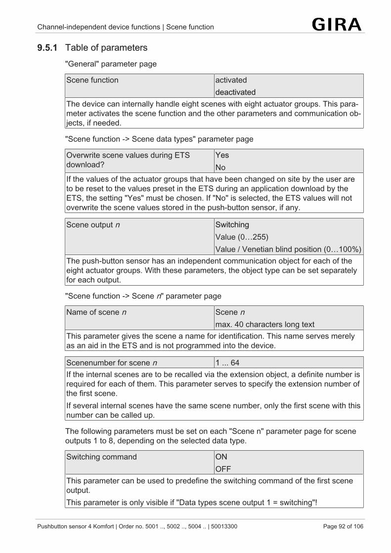
Channel-independent device functions | Scene function
Pushbutton sensor 4 Komfort | Order no. 5001 .., 5002 .., 5004 .. | 50013300 Page 92 of 106
9.5.1 Table of parameters"General" parameter page
Scene function activateddeactivated
The device can internally handle eight scenes with eight actuator groups. This para-meter activates the scene function and the other parameters and communication ob-jects, if needed.
"Scene function -> Scene data types" parameter page
Overwrite scene values during ETSdownload?
YesNo
If the values of the actuator groups that have been changed on site by the user areto be reset to the values preset in the ETS during an application download by theETS, the setting "Yes" must be chosen. If "No" is selected, the ETS values will notoverwrite the scene values stored in the push-button sensor, if any.
Scene output n SwitchingValue (0…255)Value / Venetian blind position (0…100%)
The push-button sensor has an independent communication object for each of theeight actuator groups. With these parameters, the object type can be set separatelyfor each output.
"Scene function -> Scene n" parameter page
Name of scene n Scene nmax. 40 characters long text
This parameter gives the scene a name for identification. This name serves merelyas an aid in the ETS and is not programmed into the device.
Scenenumber for scene n 1 ... 64If the internal scenes are to be recalled via the extension object, a definite number isrequired for each of them. This parameter serves to specify the extension number ofthe first scene.If several internal scenes have the same scene number, only the first scene with thisnumber can be called up.
The following parameters must be set on each "Scene n" parameter page for sceneoutputs 1 to 8, depending on the selected data type.
Switching command ONOFF
This parameter can be used to predefine the switching command of the first sceneoutput.This parameter is only visible if "Data types scene output 1 = switching"!
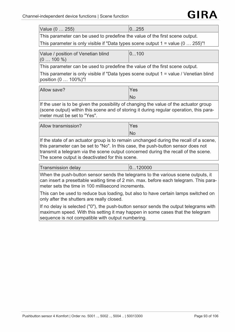
Channel-independent device functions | Scene function
Pushbutton sensor 4 Komfort | Order no. 5001 .., 5002 .., 5004 .. | 50013300 Page 93 of 106
Value (0 … 255) 0...255This parameter can be used to predefine the value of the first scene output.This parameter is only visible if "Data types scene output 1 = value (0 … 255)"!
Value / position of Venetian blind(0 … 100 %)
0...100
This parameter can be used to predefine the value of the first scene output.This parameter is only visible if "Data types scene output 1 = value / Venetian blindposition (0 … 100%)"!
Allow save? YesNo
If the user is to be given the possibility of changing the value of the actuator group(scene output) within this scene and of storing it during regular operation, this para-meter must be set to "Yes".
Allow transmission? YesNo
If the state of an actuator group is to remain unchanged during the recall of a scene,this parameter can be set to "No". In this case, the push-button sensor does nottransmit a telegram via the scene output concerned during the recall of the scene.The scene output is deactivated for this scene.
Transmission delay 0...120000When the push-button sensor sends the telegrams to the various scene outputs, itcan insert a presettable waiting time of 2 min. max. before each telegram. This para-meter sets the time in 100 millisecond increments.This can be used to reduce bus loading, but also to have certain lamps switched ononly after the shutters are really closed.If no delay is selected ("0"), the push-button sensor sends the output telegrams withmaximum speed. With this setting it may happen in some cases that the telegramsequence is not compatible with output numbering.
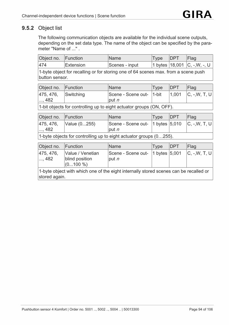
Channel-independent device functions | Scene function
Pushbutton sensor 4 Komfort | Order no. 5001 .., 5002 .., 5004 .. | 50013300 Page 94 of 106
9.5.2 Object listThe following communication objects are available for the individual scene outputs,depending on the set data type. The name of the object can be specified by the para-meter "Name of ..." .
Object no. Function Name Type DPT Flag474 Extension Scenes - input 1 bytes 18,001 C, -,W, -, U1-byte object for recalling or for storing one of 64 scenes max. from a scene pushbutton sensor.
Object no. Function Name Type DPT Flag475, 476,..., 482
Switching Scene - Scene out-put n
1-bit 1,001 C, -,W, T, U
1-bit objects for controlling up to eight actuator groups (ON, OFF).
Object no. Function Name Type DPT Flag475, 476,..., 482
Value (0...255) Scene - Scene out-put n
1 bytes 5,010 C, -,W, T, U
1-byte objects for controlling up to eight actuator groups (0…255).
Object no. Function Name Type DPT Flag475, 476,..., 482
Value / Venetianblind position(0...100 %)
Scene - Scene out-put n
1 bytes 5,001 C, -,W, T, U
1-byte object with which one of the eight internally stored scenes can be recalled orstored again.
Channel-independent device functions | Temperature measurement
Pushbutton sensor 4 Komfort | Order no. 5001 .., 5002 .., 5004 .. | 50013300 Page 95 of 106
9.6 Temperature measurement
Basic principles
The push-button sensor possesses an integrated temperature sensor, using whichthe room temperature can be detected. Alternatively (e.g. if the push-button sensorhas been installed in an unfavourable location or in case of operation in difficult con-ditions, for example, in a moist atmosphere) or additionally (e.g. in large rooms orhalls), a second, wired remote sensor or an external sensor linked via bus telegramscan be used to determine the actual value.
Temperature measurement is activated on the "General" parameter page and con-figured on the "Temperature measurement" parameter page. The device offers up totwo temperature measurements, depending on the project design of the "Room tem-perature measurement by" parameter.The room temperature measurement ("Room temperature measurement" parameterpage) is the first temperature measurement. The room temperature measurement isalways available if temperature measurement has been activated on the "General"parameter page.The second temperature measurement is referred to as the 'further temperaturemeasurement'. The further temperature measurement can be performed by the wiredremote sensor, unless the wired remote sensor is already used for room temperaturemeasurement.
When choosing the installation location for the push-button sensor or the externalsensors, the following points should be considered:
– The push-button sensor or temperature sensor should not be used in multiplecombinations, especially together with flush-mounted dimmers.
– Do not install the temperature sensor in the area of large electrical consumers(avoid heat influences).
– The push button sensor should not be installed in the vicinity of radiators orcooling systems.
– The temperature sensor should not be exposed to direct sun.– The installation of sensors on the inside of an outside wall might have a negat-
ive impact on the temperature measurement.– Temperature sensors should be installed at least 30 cm away from doors, win-
dows or ventilation units and at least 1.5 m above the floor.
Temperature measurement and measured value determination
The push-button sensor features an integrated temperature sensor. This temperaturesensor can be used to measure the ambient temperature and forward it to a roomtemperature controller via the 2-byte object "Actual temperature".
The room temperature measurement can optionally be complemented with a wiredremote sensor or an external sensor. The wired remote sensor is connected to theremote sensor terminal Device components. The external sensor is linked to thedevice (for example an additional push-button sensor or a KNX room temperaturecontroller) via the bus by means of the additional 2-byte communication object "Ex-
Channel-independent device functions | Temperature measurement
Pushbutton sensor 4 Komfort | Order no. 5001 .., 5002 .., 5004 .. | 50013300 Page 96 of 106
ternal sensor". The push-button sensor offers another temperature measurement bythe wired sensor, unless the wired sensor is already used for room temperaturemeasurement.
The "Room temperature measurement by" parameter in the "Temperature measure-ment -> Room temperature measurement" parameter node specifies the sensors todetect the room temperature. The following settings are possible:
– "internal temperature sensor"The temperature sensor integrated in the push-button sensor is activated.Thus, the actual temperature value is determined only locally on the device.The wired sensor can be used for another temperature measurement.
– "internal and wired sensor"With this setting the internal as well as the wired temperature sensor is active.The wired sensor must be a temperature sensor (see accessories).When evaluating the internal and the wired sensors, the real actual temperat-ure is made up from the two measured temperature values. The weighting ofthe temperature values is defined by the "Creation of measuring value internalagainst wired" parameter. Depending on the different locations of the sensorsor a possible non-uniform heat distribution inside the room, it is thus possibleto adjust the actual temperature measurement. Often, those temperaturesensors that are subject to negative external influences (for example, unfa-vourable location because of exposure to sun or heater or door / window dir-ectly next to it) are weighted less heavily.The wired sensor cannot be used for another temperature measurement.
– "internal and external temperature sensor"With this setting the internal as well as the external temperature sensor is act-ive. The external sensor must either be a KNX room temperature controllercoupled via the "External sensor" 2-byte object or another bus device withtemperature detection.When evaluating the internal and the external sensors, the real actual temper-ature is made up from the two measured temperature values. The weighting ofthe temperature values is defined by the "Creation of measuring value internalagainst external" parameter. Depending on the different locations of thesensors or a possible non-uniform heat distribution inside the room, it is thuspossible to adjust the actual temperature measurement. Often, those temper-ature sensors that are subject to negative external influences (for example, un-favourable location because of exposure to sun or heater or door / window dir-ectly next to it) are weighted less heavily.The wired sensor can be used for another temperature measurement.
Example:
The push-button sensor has been installed next to the entrance door (internalsensor). An additional external temperature sensor has been mounted on an innerwall in the middle of the room below the ceiling.
Channel-independent device functions | Temperature measurement
Pushbutton sensor 4 Komfort | Order no. 5001 .., 5002 .., 5004 .. | 50013300 Page 97 of 106
Internal sensor: 21.5 °CExternal sensor: 22.3 °CDetermination of measured value: 30 % to 70 %
-> TResult internal = T internal · 0.3 = 6.45 °C,-> TResult external = Texternal = 22.3 °C · 0.7 = 15.61 °C-> TResult actual = TResult internal + TResult external = 22.06 °C
Transmission of the temperature
The temperatures determined by room temperature measurement and by the furthertemperature measurement can be transmitted to the bus using the 2-byte objects"Actual temperature" or "Wired sensor" respectively.
The parameters "Transmission after room temperature change by" in the parameternode "Temperature measurement -> Room temperature measurement" or "Transmis-sion after temperature change by" in the parameter node "Temperature measure-ment -> Further temperature measurement" define the temperature values by whichthe actual value of the respective temperature measurement has to change for theactual value to be automatically transmitted via the objects "Actual temperature" or"Wired sensor". Possible temperature value changes lie within a range of0.1 K and 25.5 K. Setting to "0" at this point will deactivate the automatic transmis-sion of the actual temperature.
Additionally, the determined temperatures for the room temperature measurement orfurther temperature measurement can be transmitted cyclically. The "Cyclical trans-mission of ..." parameters define the cycle time (1 to 255 minutes). The value "0" willdeactivate the cyclical transmission of actual values.Setting the "Read" flag on the "Actual temperature" and "Wired sensor" objects makeit possible to read out the current actual values at any time over the bus. It has to bepointed out that with deactivated cyclical transmission and deactivated automatictransmission, no more temperature telegrams will be transmitted in case of changes!
Calibrating the measured values
In some cases during room temperature measurement, it may be necessary to adjustthe single temperature values. Adjustment becomes necessary, for example, if thetemperature measured by the sensors stays permanently below or above the actualtemperature in the vicinity of the sensor. To determine the temperature deviation, theactual room temperature should be detected with a reference measurement using acalibrated temperature measuring device.
The "Calibration" parameters can be used to parameterize the positive (temperatureincrease between 0.1 and 12.7 K) or negative (temperature decrease between –12.8and –0.1 K) temperature calibration in 0.1 K increments. Thus, the calibration is onlyset statically once.
The measured value has to be increased, if the value measured by the sensorlies below the actual room temperature. The measured value has to be de-creased, if the value measured by the sensor lies above the actual room tem-perature.
Channel-independent device functions | Temperature measurement
Pushbutton sensor 4 Komfort | Order no. 5001 .., 5002 .., 5004 .. | 50013300 Page 98 of 106
The "Actual temperature" object is always used to transmit the adjusted tem-perature value to the bus.When determining the measured value using combined sensors, the two ad-justed values are used to calculate the actual value.
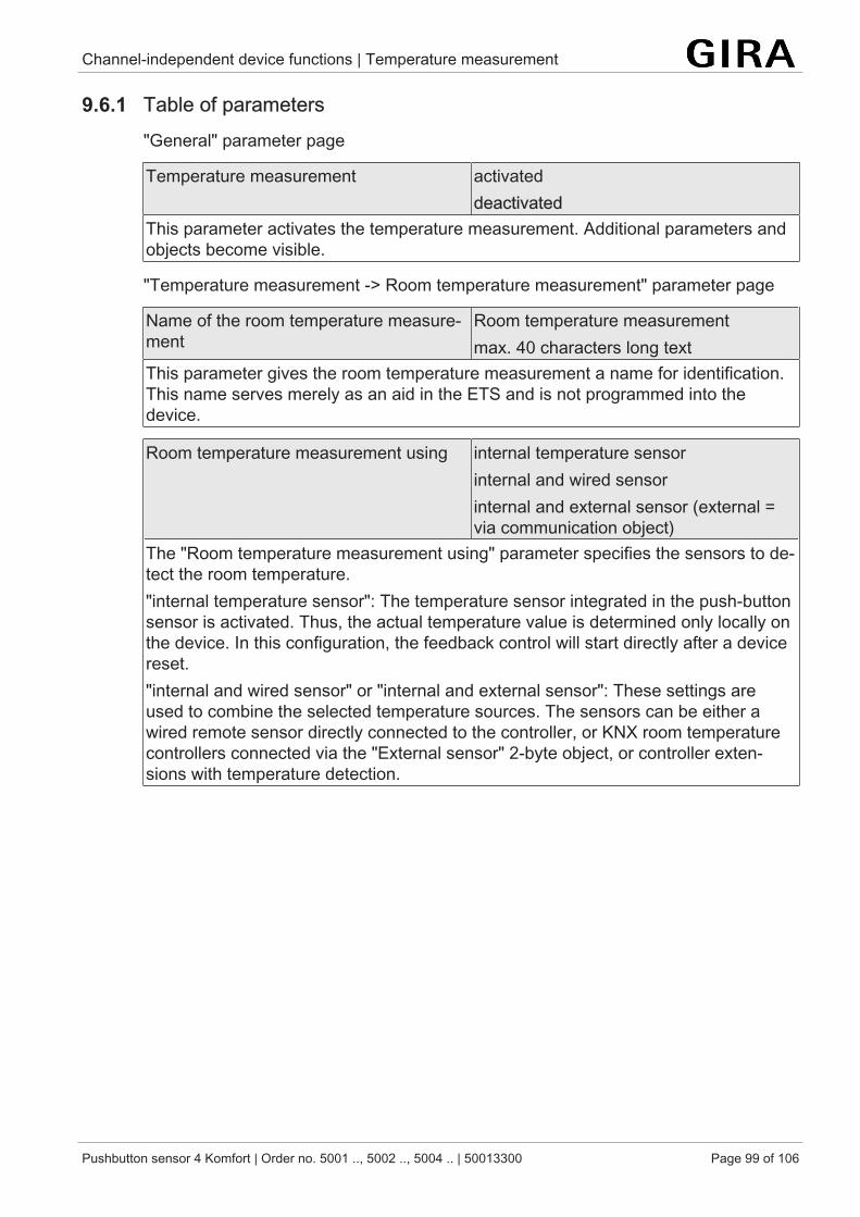
Channel-independent device functions | Temperature measurement
Pushbutton sensor 4 Komfort | Order no. 5001 .., 5002 .., 5004 .. | 50013300 Page 99 of 106
9.6.1 Table of parameters"General" parameter page
Temperature measurement activateddeactivated
This parameter activates the temperature measurement. Additional parameters andobjects become visible.
"Temperature measurement -> Room temperature measurement" parameter page
Name of the room temperature measure-ment
Room temperature measurementmax. 40 characters long text
This parameter gives the room temperature measurement a name for identification.This name serves merely as an aid in the ETS and is not programmed into thedevice.
Room temperature measurement using internal temperature sensorinternal and wired sensorinternal and external sensor (external =via communication object)
The "Room temperature measurement using" parameter specifies the sensors to de-tect the room temperature."internal temperature sensor": The temperature sensor integrated in the push-buttonsensor is activated. Thus, the actual temperature value is determined only locally onthe device. In this configuration, the feedback control will start directly after a devicereset."internal and wired sensor" or "internal and external sensor": These settings areused to combine the selected temperature sources. The sensors can be either awired remote sensor directly connected to the controller, or KNX room temperaturecontrollers connected via the "External sensor" 2-byte object, or controller exten-sions with temperature detection.
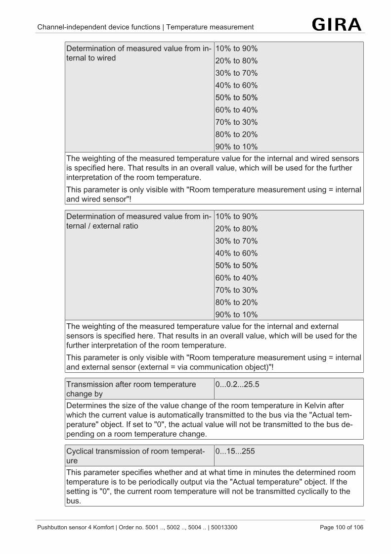
Channel-independent device functions | Temperature measurement
Pushbutton sensor 4 Komfort | Order no. 5001 .., 5002 .., 5004 .. | 50013300 Page 100 of 106
Determination of measured value from in-ternal to wired
10% to 90%20% to 80%30% to 70%40% to 60%50% to 50%60% to 40%70% to 30%80% to 20%90% to 10%
The weighting of the measured temperature value for the internal and wired sensorsis specified here. That results in an overall value, which will be used for the furtherinterpretation of the room temperature.This parameter is only visible with "Room temperature measurement using = internaland wired sensor"!
Determination of measured value from in-ternal / external ratio
10% to 90%20% to 80%30% to 70%40% to 60%50% to 50%60% to 40%70% to 30%80% to 20%90% to 10%
The weighting of the measured temperature value for the internal and externalsensors is specified here. That results in an overall value, which will be used for thefurther interpretation of the room temperature.This parameter is only visible with "Room temperature measurement using = internaland external sensor (external = via communication object)"!
Transmission after room temperaturechange by
0...0.2...25.5
Determines the size of the value change of the room temperature in Kelvin afterwhich the current value is automatically transmitted to the bus via the "Actual tem-perature" object. If set to "0", the actual value will not be transmitted to the bus de-pending on a room temperature change.
Cyclical transmission of room temperat-ure
0...15...255
This parameter specifies whether and at what time in minutes the determined roomtemperature is to be periodically output via the "Actual temperature" object. If thesetting is "0", the current room temperature will not be transmitted cyclically to thebus.
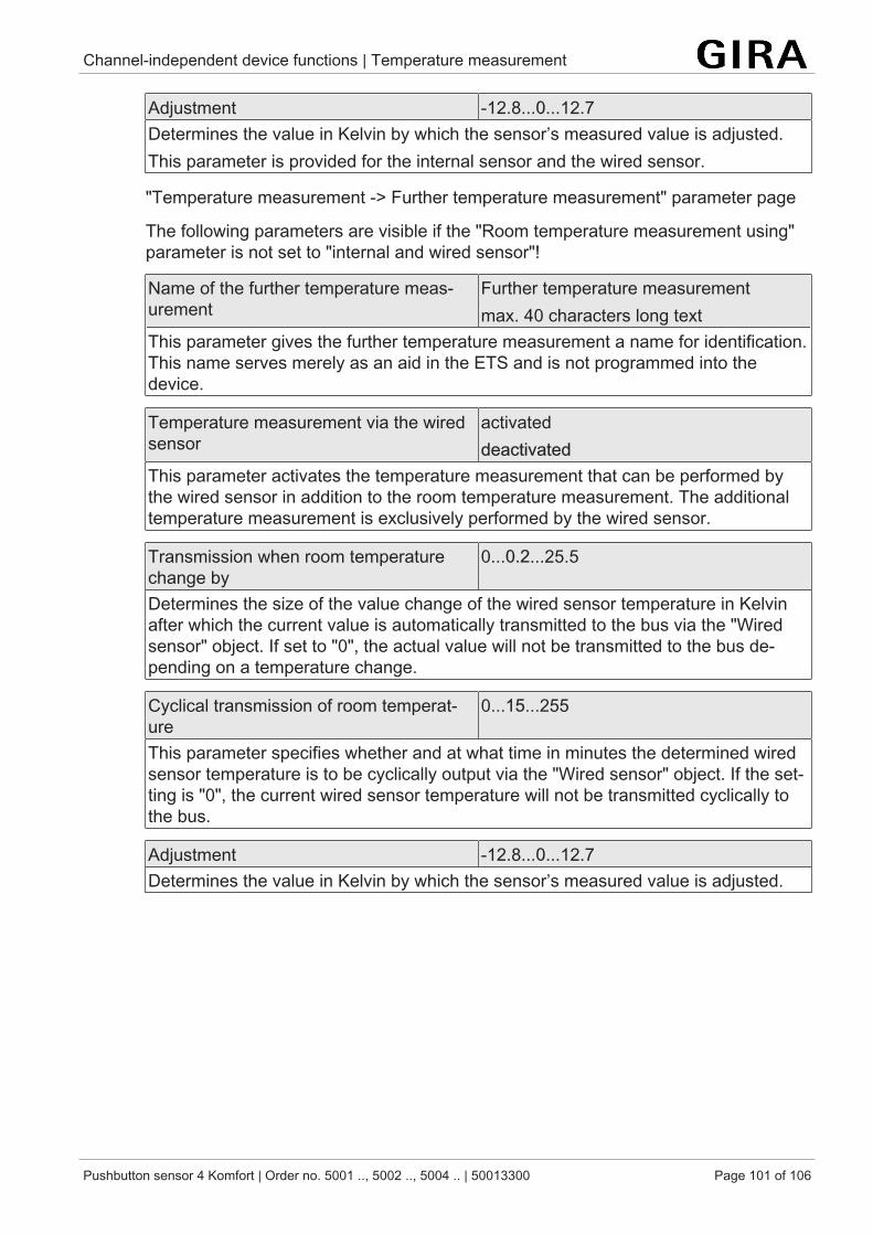
Channel-independent device functions | Temperature measurement
Pushbutton sensor 4 Komfort | Order no. 5001 .., 5002 .., 5004 .. | 50013300 Page 101 of 106
Adjustment -12.8...0...12.7Determines the value in Kelvin by which the sensor’s measured value is adjusted.This parameter is provided for the internal sensor and the wired sensor.
"Temperature measurement -> Further temperature measurement" parameter page
The following parameters are visible if the "Room temperature measurement using"parameter is not set to "internal and wired sensor"!
Name of the further temperature meas-urement
Further temperature measurementmax. 40 characters long text
This parameter gives the further temperature measurement a name for identification.This name serves merely as an aid in the ETS and is not programmed into thedevice.
Temperature measurement via the wiredsensor
activateddeactivated
This parameter activates the temperature measurement that can be performed bythe wired sensor in addition to the room temperature measurement. The additionaltemperature measurement is exclusively performed by the wired sensor.
Transmission when room temperaturechange by
0...0.2...25.5
Determines the size of the value change of the wired sensor temperature in Kelvinafter which the current value is automatically transmitted to the bus via the "Wiredsensor" object. If set to "0", the actual value will not be transmitted to the bus de-pending on a temperature change.
Cyclical transmission of room temperat-ure
0...15...255
This parameter specifies whether and at what time in minutes the determined wiredsensor temperature is to be cyclically output via the "Wired sensor" object. If the set-ting is "0", the current wired sensor temperature will not be transmitted cyclically tothe bus.
Adjustment -12.8...0...12.7Determines the value in Kelvin by which the sensor’s measured value is adjusted.
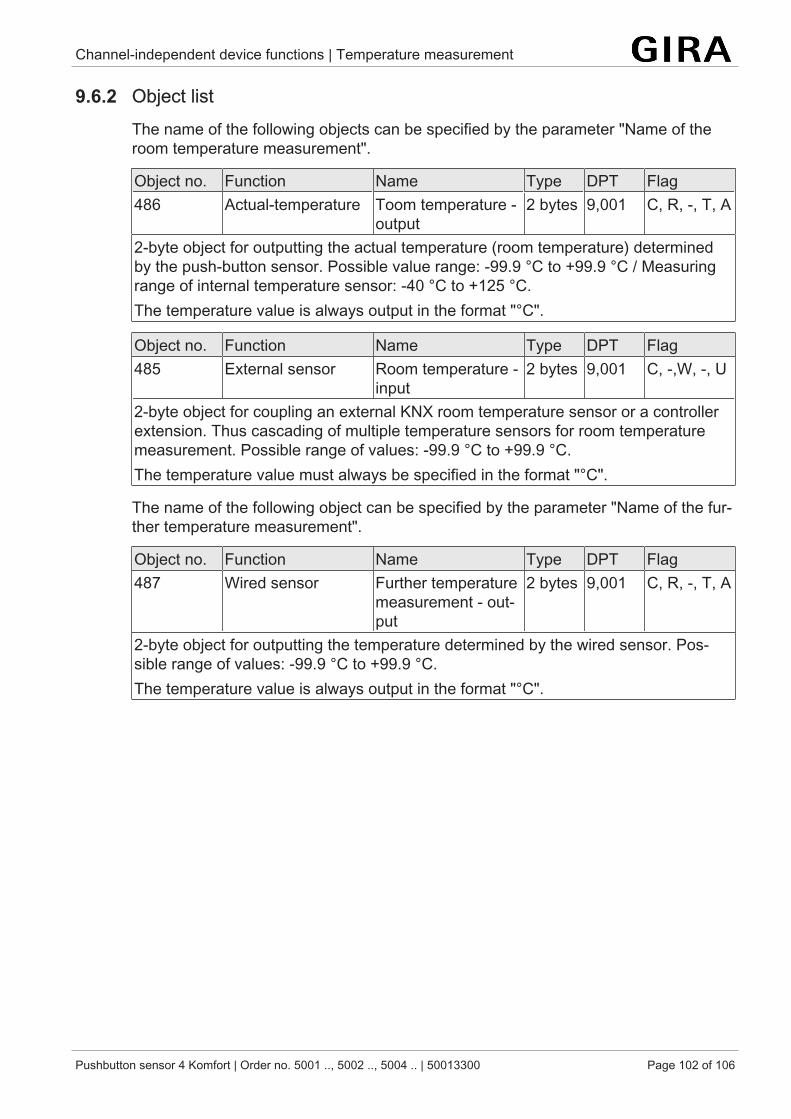
Channel-independent device functions | Temperature measurement
Pushbutton sensor 4 Komfort | Order no. 5001 .., 5002 .., 5004 .. | 50013300 Page 102 of 106
9.6.2 Object listThe name of the following objects can be specified by the parameter "Name of theroom temperature measurement".
Object no. Function Name Type DPT Flag486 Actual-temperature Toom temperature -
output2 bytes 9,001 C, R, -, T, A
2-byte object for outputting the actual temperature (room temperature) determinedby the push-button sensor. Possible value range: -99.9 °C to +99.9 °C / Measuringrange of internal temperature sensor: -40 °C to +125 °C.The temperature value is always output in the format "°C".
Object no. Function Name Type DPT Flag485 External sensor Room temperature -
input2 bytes 9,001 C, -,W, -, U
2-byte object for coupling an external KNX room temperature sensor or a controllerextension. Thus cascading of multiple temperature sensors for room temperaturemeasurement. Possible range of values: -99.9 °C to +99.9 °C.The temperature value must always be specified in the format "°C".
The name of the following object can be specified by the parameter "Name of the fur-ther temperature measurement".
Object no. Function Name Type DPT Flag487 Wired sensor Further temperature
measurement - out-put
2 bytes 9,001 C, R, -, T, A
2-byte object for outputting the temperature determined by the wired sensor. Pos-sible range of values: -99.9 °C to +99.9 °C.The temperature value is always output in the format "°C".
Channel-independent device functions | Room humidity measurement
Pushbutton sensor 4 Komfort | Order no. 5001 .., 5002 .., 5004 .. | 50013300 Page 103 of 106
9.7 Room humidity measurementThe push-button sensor possesses an integrated humidity sensor that can be used todetect the room humidity.
Room humidity measurement is activated on the "General" parameter page and con-figured on the "Room humidity measurement" parameter page.
Transmission of room humidity
The determined room humidity can be transmitted to the bus via the "Actual humidity"2-byte object.
The parameter "Transmission after room humidity change by" in the parameter node"Room humidity measurement" defines the humidity value by which the humiditymeasurement actual value has to change for the actual value to be transmitted auto-matically via the "Actual humidity" object. Humidity value changes between0% and 25% are possible. Setting to "0" at this point will deactivate the automatictransmission of the room humidity.
In addition, the determined room humidity can be transmitted cyclically. The "Cyclicaltransmission of room humidity" parameter determines the cycle time(1 to 255 minutes). The value "0" will deactivate the cyclical transmission of the ac-tual value.Setting the "Read" flag on the "actual humidity" object makes it possible to read outthe current actual value at any time over the bus. It has to be pointed out that withdeactivated cyclical transmission and deactivated automatic transmission, no morehumidity telegrams will be transmitted in case of changes!
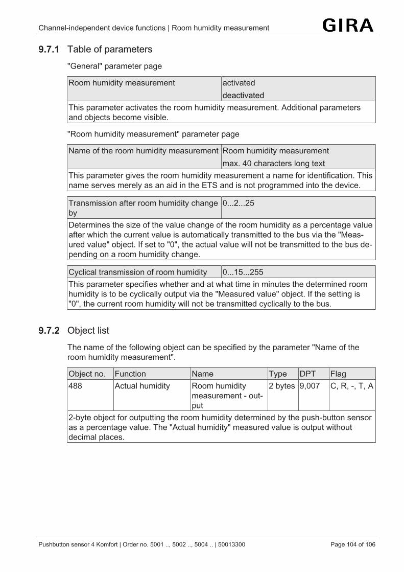
Channel-independent device functions | Room humidity measurement
Pushbutton sensor 4 Komfort | Order no. 5001 .., 5002 .., 5004 .. | 50013300 Page 104 of 106
9.7.1 Table of parameters"General" parameter page
Room humidity measurement activateddeactivated
This parameter activates the room humidity measurement. Additional parametersand objects become visible.
"Room humidity measurement" parameter page
Name of the room humidity measurement Room humidity measurementmax. 40 characters long text
This parameter gives the room humidity measurement a name for identification. Thisname serves merely as an aid in the ETS and is not programmed into the device.
Transmission after room humidity changeby
0...2...25
Determines the size of the value change of the room humidity as a percentage valueafter which the current value is automatically transmitted to the bus via the "Meas-ured value" object. If set to "0", the actual value will not be transmitted to the bus de-pending on a room humidity change.
Cyclical transmission of room humidity 0...15...255This parameter specifies whether and at what time in minutes the determined roomhumidity is to be cyclically output via the "Measured value" object. If the setting is"0", the current room humidity will not be transmitted cyclically to the bus.
9.7.2 Object listThe name of the following object can be specified by the parameter "Name of theroom humidity measurement".
Object no. Function Name Type DPT Flag488 Actual humidity Room humidity
measurement - out-put
2 bytes 9,007 C, R, -, T, A
2-byte object for outputting the room humidity determined by the push-button sensoras a percentage value. The "Actual humidity" measured value is output withoutdecimal places.
Channel-independent device functions | Transmission delay
Pushbutton sensor 4 Komfort | Order no. 5001 .., 5002 .., 5004 .. | 50013300 Page 105 of 106
9.8 Transmission delayThe transmission delay is determined by the push-button sensor from the devicenumber of its physical address (phys. address: area.line.device number). The higherthe device number of the push-button sensor, the longer its transmission delay. Thetransmission delay can be up to 30 seconds maximum (device number = 255).
The transmission delay is permanently activated in the push-button sensor. Thetransmission delay reduces the load on the bus by preventing multiple push-buttonsensors used in a project from simultaneously attempting to transmit telegrams to thebus. The transmission delay exclusively applies to the 'Read on init' function. 'Readon init' enforces updating of the communication object value using a read requestwhen the device is switched on. Communication objects will perform 'Read on init' ifthe I flag and the T flag are activated.
After a programming operation (phys. address or application program) or after busvoltage has been activated, the push-button sensor will then attempt to query currentvalues (e.g. operating mode, presence function, setpoint shift) using the correspond-ing communication objects via the bus, for example from a room temperature control-ler. The push-button sensor updates its object statuses in this way.
By default, no I flags are activated in the push-button sensor parameterisation.
The transmit delay is not active for the rocker and button functions of the pushbutton sensor.
Contact
Pushbutton sensor 4 Komfort | Order no. 5001 .., 5002 .., 5004 .. | 50013300 Page 106 of 106
GiraGiersiepen GmbH & Co. KGElektro-Installations-Systeme
Industriegebiet MermbachDahlienstraße42477 Radevormwald
Postfach 12 2042461 Radevormwald
Deutschland
Tel +49(0)21 95 - 602-0Fax +49(0)21 95 - 602-191