tailbeacon stc installation manual - uavionix€¦ · guide” uav-1002185-001 section 10 to...
TRANSCRIPT
UAV-1002514-001 Rev B
tailBeaconTM STC
Installation Manual
UAV-1002514-001 2 Rev B
© 2019 uAvionix Corporation. All rights reserved.
Except as expressly provided herein, no part of this guide may be
reproduced, transmitted, disseminated, downloaded or stored in any
storage medium, for any purpose without the express written permission of
uAvionix. uAvionix grants permissions to download a single copy of this
guide onto an electronic storage medium to be viewed for personal use,
provided that the complete text of this copyright notice is retained.
Unauthorized commercial distribution of this manual or any revision hereto
is strictly prohibited.
uAvionix® and Ping® are registered trademarks of uAvionix Corporation and
may not be used without express permission of uAvionix.
tailBeacon, skyBeacon, Continuous Calibration, Power Transcoder, Echo
Installer, and Ping Installer are trademarks of uAvionix Corporation and
may not be used without express permission of uAvionix.
Patent uavionix.com/patents
UAV-1002514-001 3 Rev B
1 Revision History
Revision Date Comments
A 7/7/2019 Initial release
B 8/28/2019 Update ADS-B version to v1.4.0 and note installation kit
UAV-1002514-001 4 Rev B
2 Warnings / Disclaimers
uAvionix is not liable for damages arising from the use or misuse of this
product.
This equipment is classified by the United States Department of Commerce's Bureau of Industry and Security (BIS) as Export Control Classification Number (ECCN) 7A994. These items are controlled by the U.S. Government and authorized for export only to the country of ultimate destination for use by the ultimate consignee or end-user(s) herein identified. They may not be resold, transferred, or otherwise disposed of, to any other country or to any person other than the authorized ultimate consignee or end-user(s), either in their original form or after being incorporated into other items, without first obtaining approval from the U.S. government or as otherwise authorized by U.S. law and regulations.
UAV-1002514-001 5 Rev B
3 Table of Contents
1 Revision History ................................................................................... 3
2 Warnings / Disclaimers ........................................................................ 4
3 Table of Contents ................................................................................ 5
4 System Information .............................................................................. 6
4.1 Certification ................................................................................... 6
4.2 TSO Authorization ......................................................................... 6
4.3 System Limitations ........................................................................ 7
5 System Specifications .......................................................................... 8
5.1 Physical Specifications ................................................................. 8
5.2 System Interfaces ......................................................................... 9
6 Installation ......................................................................................... 10
6.1 Unpacking and Inspecting ........................................................... 10
6.2 Mounting ..................................................................................... 10
6.3 Unit Installation Overview ............................................................ 11
6.4 Mounting Dimensions ................................................................. 12
6.5 Mounting Procedure .................................................................... 13
6.6 tailBeacon System Configuration ................................................ 17
6.6.1 Verify Software Version ......................................................... 17
6.6.2 Configure Device ................................................................... 17
6.7 Flight Checks .............................................................................. 18
7 Support .............................................................................................. 18
UAV-1002514-001 6 Rev B
4 System Information
4.1 Certification
This installation manual provides mechanical and electrical information
necessary to install tailBeacon. The content of this manual assumes use
by competent and qualified personnel using standard maintenance
procedures in accordance with Title 14 of the Code of Federal Regulation
and other related accepted procedures.
Those installing this article on an aircraft listed on the Approved Models List
shall verify the compatibility of existing STCs with this STC prior to
returning the aircraft to service.
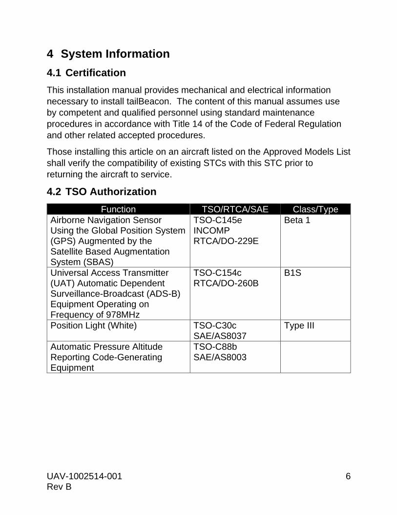
4.2 TSO Authorization
Function TSO/RTCA/SAE Class/Type
Airborne Navigation Sensor Using the Global Position System (GPS) Augmented by the Satellite Based Augmentation System (SBAS)
TSO-C145e INCOMP RTCA/DO-229E
Beta 1
Universal Access Transmitter (UAT) Automatic Dependent Surveillance-Broadcast (ADS-B) Equipment Operating on Frequency of 978MHz
TSO-C154c RTCA/DO-260B
B1S
Position Light (White) TSO-C30c SAE/AS8037
Type III
Automatic Pressure Altitude Reporting Code-Generating Equipment
TSO-C88b SAE/AS8003
UAV-1002514-001 7 Rev B
4.3 System Limitations
Installation
This article meets the minimum performance and quality control standards
required by a technical standard order (TSO) and when installed on aircraft
approved on the AML can be approved for return to service after
installation.
If you are installing this article on or in a specific type or class of aircraft,
not listed on the AML you must obtain separate approval for installation.
TCAS/ACAS System
tailBeacon does not support installation on aircraft with an active Airborne
Collision Avoidance System (ACAS) with Resolution Advisory capability,
such as TCAS II or ACAS X.
SatCom
The tailBeacon GPS has not been demonstrated as compatible with
SatCom equipment and should not be installed on SatCom equipped
aircraft.
Transponder
A companion altitude-reporting transponder is required to be installed for
14 CFR 91.225 and 91.227 compliance, unless installed on an aircraft
excepted from the requirements of 14 CFR 91.215 and 91.225.
The transponder’s altitude source must comply with TSO-C10(), TSO-
C106() or TSO-C88() and meet the requirements of 14 CFR 91.217.
Transponder antenna
tailBeacon must be installed at least 3 feet from any operating transponder
antenna.
UAV-1002514-001 8 Rev B
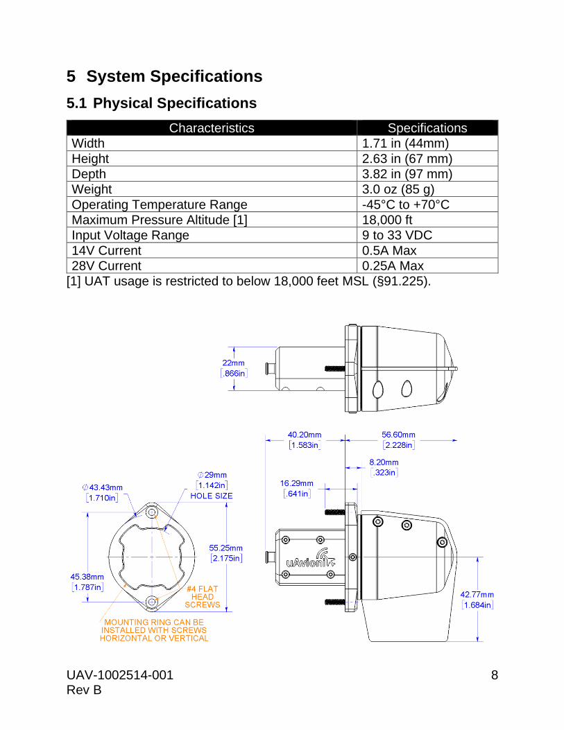
5 System Specifications
5.1 Physical Specifications
Characteristics Specifications
Width 1.71 in (44mm)
Height 2.63 in (67 mm)
Depth 3.82 in (97 mm)
Weight 3.0 oz (85 g)
Operating Temperature Range -45°C to +70°C
Maximum Pressure Altitude [1] 18,000 ft
Input Voltage Range 9 to 33 VDC
14V Current 0.5A Max
28V Current 0.25A Max
[1] UAT usage is restricted to below 18,000 feet MSL (§91.225).
UAV-1002514-001 9 Rev B
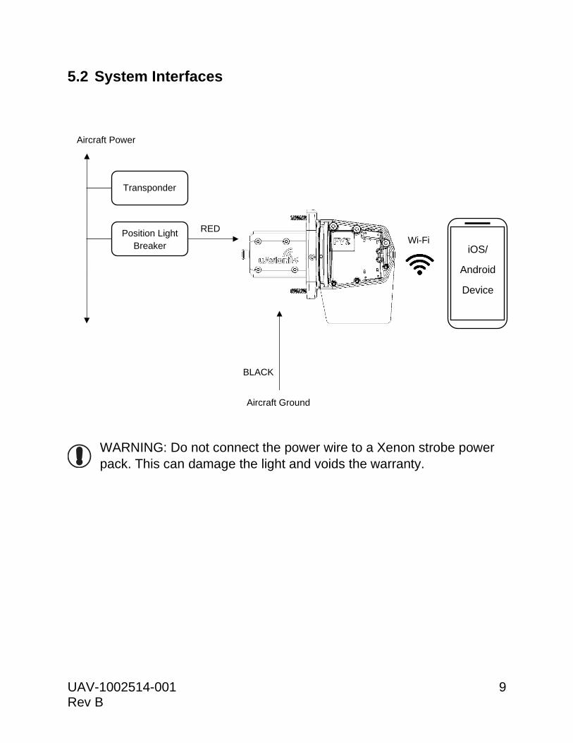
5.2 System Interfaces
WARNING: Do not connect the power wire to a Xenon strobe power
pack. This can damage the light and voids the warranty.
Position Light Breaker
Transponder
Aircraft Power
(14/28V)
RED
Aircraft Ground
BLACK
Wi-Fi iOS/
Android
Device
!
UAV-1002514-001 10 Rev B
6 Installation
6.1 Unpacking and Inspecting
Carefully unpack the device and make a visual inspection of the unit for
evidence of any damage incurred during shipment. If the unit is damaged,
notify the shipping company to file a claim for the damage. To justify your
claim, save the original shipping container and all packing materials.
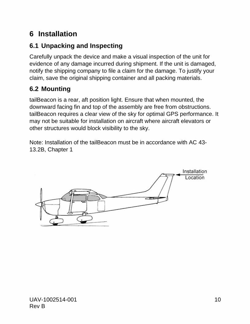
6.2 Mounting
tailBeacon is a rear, aft position light. Ensure that when mounted, the
downward facing fin and top of the assembly are free from obstructions.
tailBeacon requires a clear view of the sky for optimal GPS performance. It
may not be suitable for installation on aircraft where aircraft elevators or
other structures would block visibility to the sky.
Note: Installation of the tailBeacon must be in accordance with AC 43-
13.2B, Chapter 1
UAV-1002514-001 11 Rev B
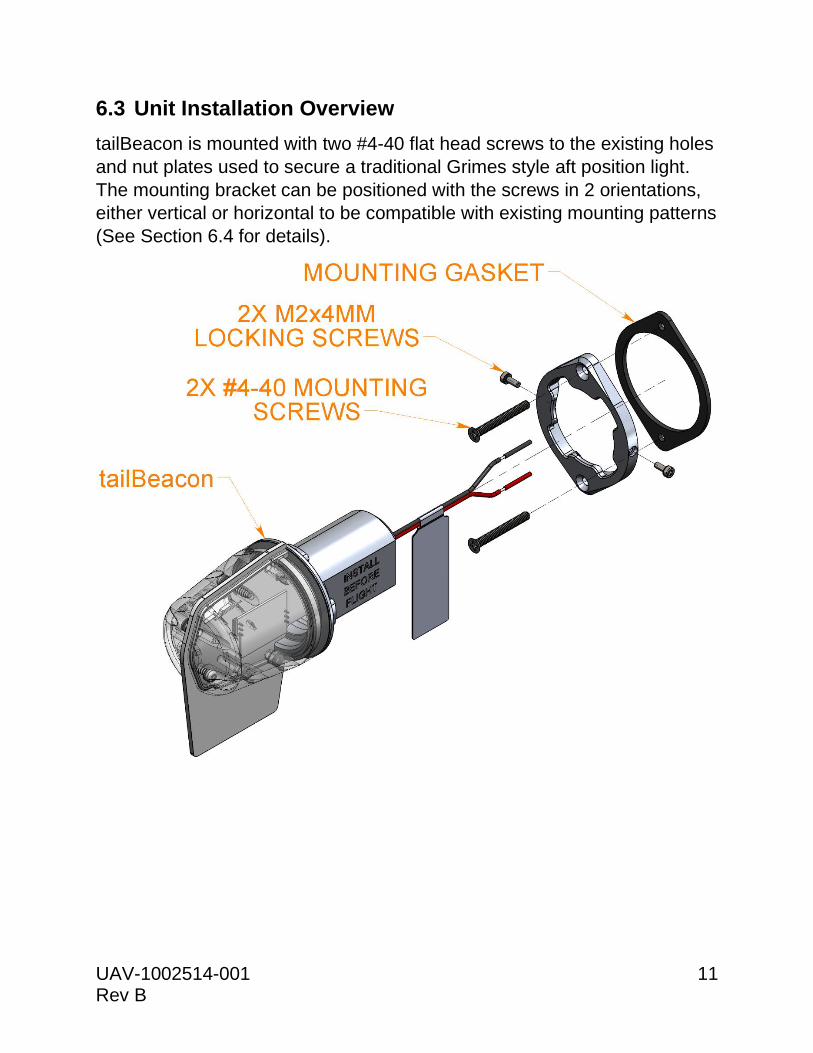
6.3 Unit Installation Overview
tailBeacon is mounted with two #4-40 flat head screws to the existing holes
and nut plates used to secure a traditional Grimes style aft position light.
The mounting bracket can be positioned with the screws in 2 orientations,
either vertical or horizontal to be compatible with existing mounting patterns
(See Section 6.4 for details).
UAV-1002514-001 12 Rev B
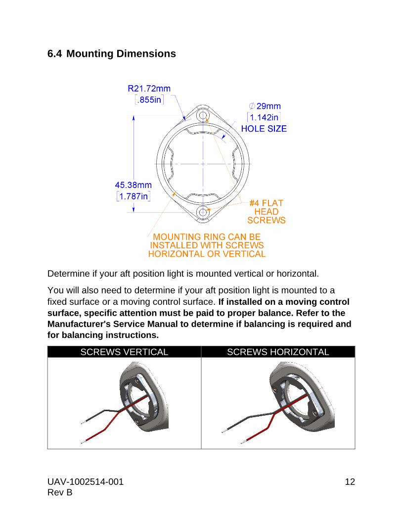
6.4 Mounting Dimensions
Determine if your aft position light is mounted vertical or horizontal.
You will also need to determine if your aft position light is mounted to a
fixed surface or a moving control surface. If installed on a moving control
surface, specific attention must be paid to proper balance. Refer to the
Manufacturer's Service Manual to determine if balancing is required and
for balancing instructions.
SCREWS VERTICAL SCREWS HORIZONTAL
UAV-1002514-001 13 Rev B
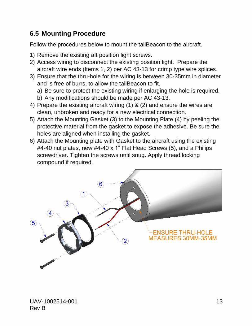
6.5 Mounting Procedure
Follow the procedures below to mount the tailBeacon to the aircraft.
1) Remove the existing aft position light screws.
2) Access wiring to disconnect the existing position light. Prepare the
aircraft wire ends (Items 1, 2) per AC 43-13 for crimp type wire splices.
3) Ensure that the thru-hole for the wiring is between 30-35mm in diameter
and is free of burrs, to allow the tailBeacon to fit.
a) Be sure to protect the existing wiring if enlarging the hole is required.
b) Any modifications should be made per AC 43-13.
4) Prepare the existing aircraft wiring (1) & (2) and ensure the wires are
clean, unbroken and ready for a new electrical connection.
5) Attach the Mounting Gasket (3) to the Mounting Plate (4) by peeling the
protective material from the gasket to expose the adhesive. Be sure the
holes are aligned when installing the gasket.
6) Attach the Mounting plate with Gasket to the aircraft using the existing
#4-40 nut plates, new #4-40 x 1” Flat Head Screws (5), and a Philips
screwdriver. Tighten the screws until snug. Apply thread locking
compound if required.
UAV-1002514-001 14 Rev B
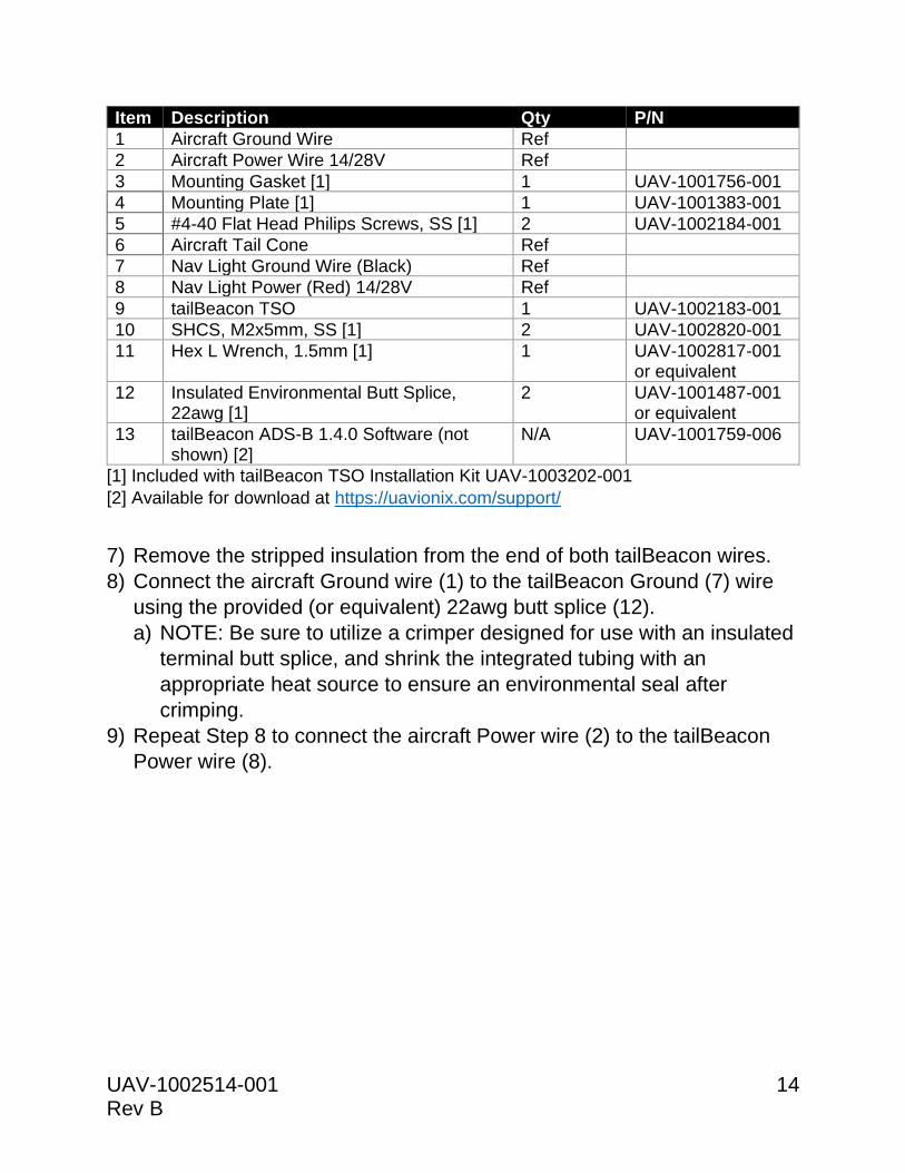
Item Description Qty P/N
1 Aircraft Ground Wire Ref
2 Aircraft Power Wire 14/28V Ref
3 Mounting Gasket [1] 1 UAV-1001756-001
4 Mounting Plate [1] 1 UAV-1001383-001
5 #4-40 Flat Head Philips Screws, SS [1] 2 UAV-1002184-001
6 Aircraft Tail Cone Ref
7 Nav Light Ground Wire (Black) Ref
8 Nav Light Power (Red) 14/28V Ref
9 tailBeacon TSO 1 UAV-1002183-001
10 SHCS, M2x5mm, SS [1] 2 UAV-1002820-001
11 Hex L Wrench, 1.5mm [1] 1 UAV-1002817-001 or equivalent
12 Insulated Environmental Butt Splice, 22awg [1]
2 UAV-1001487-001 or equivalent
13 tailBeacon ADS-B 1.4.0 Software (not shown) [2]
N/A UAV-1001759-006
[1] Included with tailBeacon TSO Installation Kit UAV-1003202-001
[2] Available for download at https://uavionix.com/support/
7) Remove the stripped insulation from the end of both tailBeacon wires.
8) Connect the aircraft Ground wire (1) to the tailBeacon Ground (7) wire
using the provided (or equivalent) 22awg butt splice (12).
a) NOTE: Be sure to utilize a crimper designed for use with an insulated
terminal butt splice, and shrink the integrated tubing with an
appropriate heat source to ensure an environmental seal after
crimping.
9) Repeat Step 8 to connect the aircraft Power wire (2) to the tailBeacon
Power wire (8).
UAV-1002514-001 15 Rev B
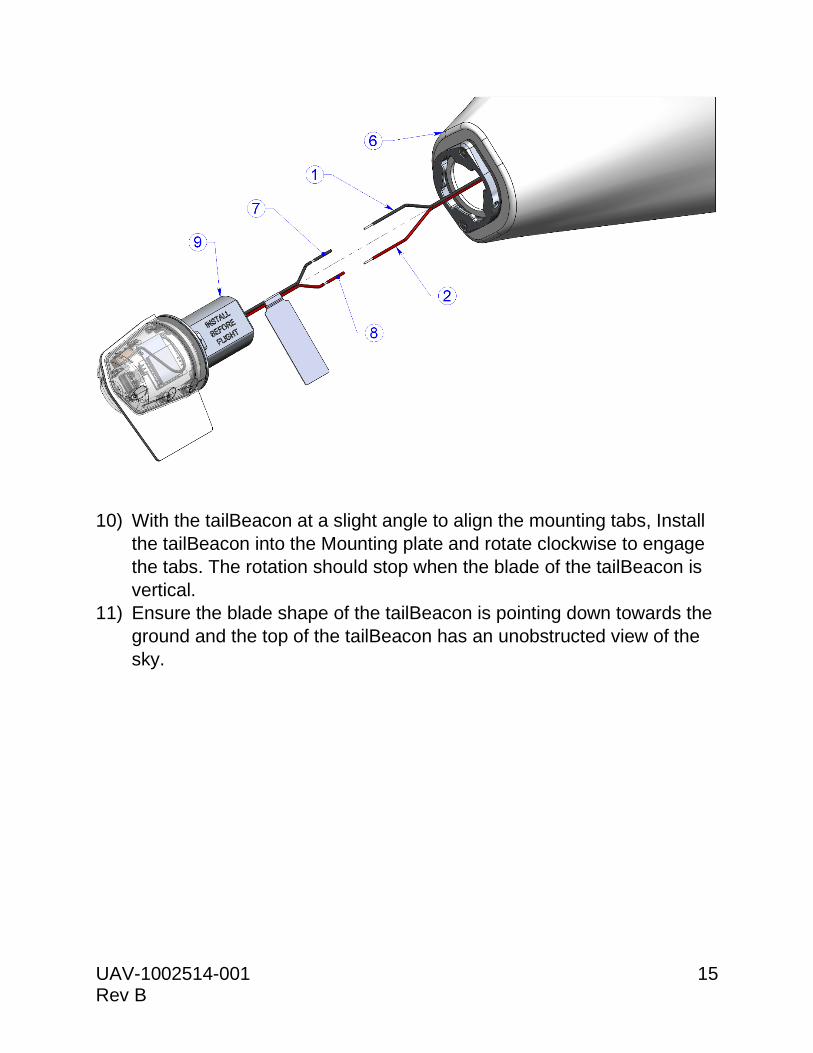
10) With the tailBeacon at a slight angle to align the mounting tabs, Install
the tailBeacon into the Mounting plate and rotate clockwise to engage
the tabs. The rotation should stop when the blade of the tailBeacon is
vertical.
11) Ensure the blade shape of the tailBeacon is pointing down towards the
ground and the top of the tailBeacon has an unobstructed view of the
sky.
UAV-1002514-001 16 Rev B
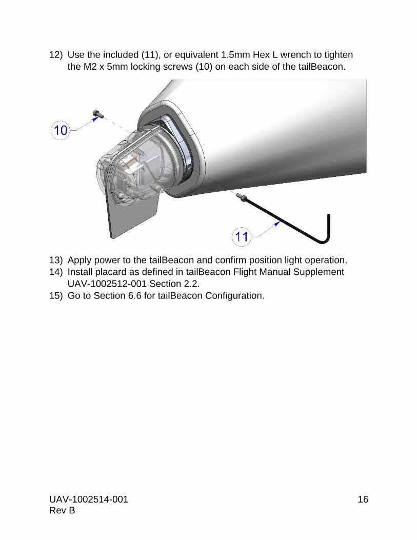
12) Use the included (11), or equivalent 1.5mm Hex L wrench to tighten
the M2 x 5mm locking screws (10) on each side of the tailBeacon.
13) Apply power to the tailBeacon and confirm position light operation.
14) Install placard as defined in tailBeacon Flight Manual Supplement
UAV-1002512-001 Section 2.2.
15) Go to Section 6.6 for tailBeacon Configuration.
UAV-1002514-001 17 Rev B
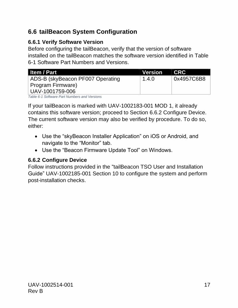
6.6 tailBeacon System Configuration
6.6.1 Verify Software Version
Before configuring the tailBeacon, verify that the version of software
installed on the tailBeacon matches the software version identified in Table
6-1 Software Part Numbers and Versions.
Item / Part Version CRC
ADS-B (skyBeacon PF007 Operating Program Firmware) UAV-1001759-006
1.4.0 0x4957C6B8
Table 6-1 Software Part Numbers and Versions
If your tailBeacon is marked with UAV-1002183-001 MOD 1, it already
contains this software version; proceed to Section 6.6.2 Configure Device.
The current software version may also be verified by procedure. To do so,
either:
• Use the “skyBeacon Installer Application” on iOS or Android, and
navigate to the “Monitor” tab.
• Use the “Beacon Firmware Update Tool” on Windows.
6.6.2 Configure Device
Follow instructions provided in the “tailBeacon TSO User and Installation
Guide” UAV-1002185-001 Section 10 to configure the system and perform
post-installation checks.
UAV-1002514-001 18 Rev B
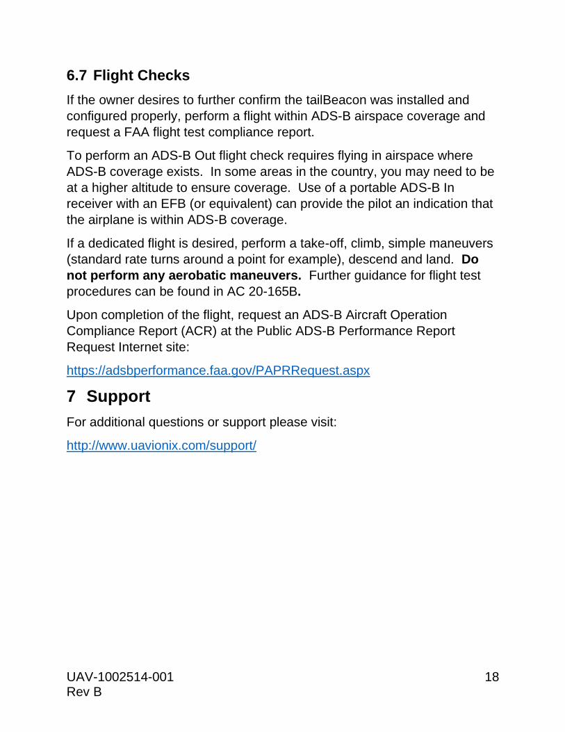
6.7 Flight Checks
If the owner desires to further confirm the tailBeacon was installed and
configured properly, perform a flight within ADS-B airspace coverage and
request a FAA flight test compliance report.
To perform an ADS-B Out flight check requires flying in airspace where
ADS-B coverage exists. In some areas in the country, you may need to be
at a higher altitude to ensure coverage. Use of a portable ADS-B In
receiver with an EFB (or equivalent) can provide the pilot an indication that
the airplane is within ADS-B coverage.
If a dedicated flight is desired, perform a take-off, climb, simple maneuvers
(standard rate turns around a point for example), descend and land. Do
not perform any aerobatic maneuvers. Further guidance for flight test
procedures can be found in AC 20-165B.
Upon completion of the flight, request an ADS-B Aircraft Operation
Compliance Report (ACR) at the Public ADS-B Performance Report
Request Internet site:
https://adsbperformance.faa.gov/PAPRRequest.aspx
7 Support
For additional questions or support please visit:
http://www.uavionix.com/support/