skybeacon user and installation guide uav-1001421-001 · uav-1001421-001 8 rev c 5 tso and system...
TRANSCRIPT

UAV-1001421-001 Rev C
skyBeaconTM TSO
User and Installation Guide

UAV-1001421-001 2 Rev C
© 2018 uAvionix Corporation. All rights reserved.
Except as expressly provided herein, no part of this guide may be
reproduced, transmitted, disseminated, downloaded or stored in any
storage medium, for any purpose without the express written permission of
uAvionix. uAvionix grants permissions to download a single copy of this
guide onto an electronic storage medium to be viewed for personal use,
provided that the complete text of this copyright notice is retained.
Unauthorized commercial distribution of this manual or any revision hereto
is strictly prohibited.
uAvionix® and Ping® are registered trademarks of uAvionix Corporation and
may not be used without express permission of uAvionix.
skyBeacon, Continuous Calibration, Power Transcoder, Echo Installer, and
Ping Installer are trademarks of uAvionix Corporation and may not be used
without express permission of uAvionix.
skyBeacon technologies are patent pending.

UAV-1001421-001 3 Rev C
1 Revision History
Revision Date Comments
A 8/8/2018 Initial release
B 8/22/2018 Update anonymous mode, limitations, and electrical information
C 8/31/2018 Add limitation for distance to transponder antenna
UAV-1001421-001 4 Rev C
2 Warnings / Disclaimers
All device operational procedures must be learned on the ground.
uAvionix is not liable for damages arising from the use or misuse of this
product.
This equipment is classified by the United States Department of Commerce's Bureau of Industry and Security (BIS) as Export Control Classification Number (ECCN) 7A994. These items are controlled by the U.S. Government and authorized for export only to the country of ultimate destination for use by the ultimate consignee or end-user(s) herein identified. They may not be resold, transferred, or otherwise disposed of, to any other country or to any person other than the authorized ultimate consignee or end-user(s), either in their original form or after being incorporated into other items, without first obtaining approval from the U.S. government or as otherwise authorized by U.S. law and regulations.

UAV-1001421-001 5 Rev C
3 Limited Warranty
uAvionix products are warranted to be free from defects in material and
workmanship for one year from the installation of skyBeacon in the aircraft.
For the duration of the warranty period, uAvionix, at its sole option, will
repair or replace any product which fails in normal use. Such repairs or
replacement will be made at no charge to the customer for parts or labor,
provided that the customer shall be responsible for any transportation cost.
Restrictions: This warranty does not apply to cosmetic damage,
consumable parts, damage caused by accident, abuse, misuse, fire or
flood, theft, damage caused by unauthorized servicing, or product that has
been modified or altered.
Disclaimer of Warranty: IN NO EVENT, SHALL UAVIONIX BE LIABLE
FOR ANY INCIDENTAL, SPECIAL, INDIRECT OR CONSEQUENTIAL
DAMAGES, WHETHER RESULTING FROM THE USE, MISUSE OR
INABILITY TO USE THE PRODUCT OR FROM DEFECTS IN THE
PRODUCT. SOME STATES DO NOT ALLOW THE EXCLUSION OF
INCIDENTAL OR CONSEQUENTIAL DAMAGES, SO THE ABOVE
LIMITATIONS MAY NOT APPLY TO YOU.
Warranty Service: Warranty repair service shall be provided directly by
uAvionix. Proof of purchase for the product from uAvionix or authorized
reseller is required to obtain and better expedite warranty service.
Please email or call uAvionix support with a description of the problem you
are experiencing. Also, please provide the model, serial number, shipping
address and a daytime contact number.
You will be promptly contacted with further troubleshooting steps or return
instructions. It is recommended to use a shipping method with tracking and
insurance.

UAV-1001421-001 6 Rev C
4 Table of Contents
1 Revision History ................................................................................... 3
2 Warnings / Disclaimers ........................................................................ 4
3 Limited Warranty .................................................................................. 5
4 Table of Contents ................................................................................ 6
5 TSO and System Information ............................................................... 8
5.1 Certification ................................................................................... 8
5.2 TSO Authorization ......................................................................... 9
5.3 Applicable P/Ns ............................................................................ 9
5.4 System Functions ......................................................................... 9
5.5 TSO Deviations and Incomplete .................................................. 10
5.6 FCC ID ........................................................................................ 11
5.7 Device Marking ........................................................................... 11
5.8 Environmental Qualification Form ............................................... 12
5.9 Continued Airworthiness ............................................................. 13
5.10 System Limitations ...................................................................... 13
6 System Specifications ........................................................................ 14
6.1 System Functionality ................................................................... 14
6.2 Altitude Encoder with Continuous Calibration™ .......................... 14
6.3 Power Line Transponder Monitor ................................................ 14
6.4 Anonymous Mode ....................................................................... 15
6.5 Wi-Fi ........................................................................................... 15
6.6 Call Sign ..................................................................................... 15
6.7 skyBeacon Specifications ........................................................... 16
6.7.1 Physical Specifications .......................................................... 16
6.7.2 GPS/SBAS Specifications ..................................................... 17
6.7.3 Altitude Encoder Specifications ............................................. 17

UAV-1001421-001 7 Rev C
6.7.4 978MHz UAT Specifications .................................................. 17
6.7.5 System Interfaces .................................................................. 18
7 Installation ......................................................................................... 19
7.1 Part Numbers .............................................................................. 19
7.2 Unpacking and Inspecting ........................................................... 19
7.3 Mounting ..................................................................................... 19
7.4 Wiring ......................................................................................... 20
7.5 Unit Installation ........................................................................... 21
7.6 Mounting Dimensions ................................................................. 22
8 Maintenance ...................................................................................... 23
9 Care and Cautions ............................................................................. 23
10 System Configuration ........................................................................ 23
10.1 Connect to skyBeacon Wi-Fi ....................................................... 24
10.2 Configuration .............................................................................. 25
10.2.1 Configure ............................................................................... 25
10.3 Post-Installation Checks.............................................................. 27
10.4 Post-Flight and Annual Checks ................................................... 28
11 Normal Operation .............................................................................. 29
12 Support .............................................................................................. 29

UAV-1001421-001 8 Rev C
5 TSO and System Information
5.1 Certification
This installation manual provides mechanical and electrical information
necessary to install skyBeacon. It is not equivalent to an approved
airframe-specific maintenance manual, installation design drawing, or
installation data package. The content of this manual assumes use by
competent and qualified personnel using standard maintenance procedures
in accordance with Title 14 of the Code of Federal Regulation and other
related accepted procedures. The conditions and tests required for
approval of this article are minimum performance standards. Those
installing this article either on or within a specific type or class of aircraft
must determine that the aircraft installation conditions are within the
standards which include any accepted integrated functions not specified by
the standards. TSO articles, articles approved with 14 CFR Part 21.8(d),
and any accepted integrated function(s) not specified in the standard must
have separate approval for installation in an aircraft. The article may be
installed only according to 14 CFR Part 43 or the applicable airworthiness
requirements. This is an incomplete system intended to provide the
functions identified in, and when installed according to this installation
manual.

UAV-1001421-001 9 Rev C
5.2 TSO Authorization
Function TSO/RTCA/SAE Class/Type
Airborne Navigation Sensor Using the Global Position System (GPS) Augmented by the Satellite Based Augmentation System (SBAS)
TSO-C145d INCOMP RTCA/DO-229D
Beta 1
Universal Access Transmitter (UAT) Automatic Dependent Surveillance-Broadcast (ADS-B) Equipment Operating on Frequency of 978MHz
TSO-C154c RTCA/DO-260B
B1S
Automatic Pressure Altitude Reporting Code-Generating Equipment
TSO-C88b SAE/AS8003
Position Light (Red) TSO-C30c SAE/AS8037
Type I
Anti-Collision Light TSO-C96a SAE/AS8017D
Class II
5.3 Applicable P/Ns
Description P/Ns
skyBeacon PF007 Boot Program Firmware UAV-1001758-001
skyBeacon PF007 Operating Program Firmware UAV-1001759-001
skyBeacon GNSS Operating Program Firmware UAV-1001760-001
skyBeacon Wi-Fi Operating Program Firmware UAV-1001761-001
skyBeacon Transponder Monitor Firmware UAV-1001762-001
5.4 System Functions
System Function DO-178C DAL DO-254 DAL
GPS/SBAS C C
UAT Transmission C C
Transponder Monitor C C
Altitude Encoder C C
Wi-Fi [1] E E
[1] Wi-Fi not intended for and disabled during airborne operation
UAV-1001421-001 10 Rev C
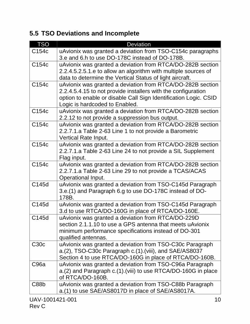
5.5 TSO Deviations and Incomplete
TSO Deviation
C154c uAvionix was granted a deviation from TSO-C154c paragraphs 3.e and 6.h to use DO-178C instead of DO-178B.
C154c uAvionix was granted a deviation from RTCA/DO-282B section 2.2.4.5.2.5.1.e to allow an algorithm with multiple sources of data to determine the Vertical Status of light aircraft.
C154c uAvionix was granted a deviation from RTCA/DO-282B section 2.2.4.5.4.15 to not provide installers with the configuration option to enable or disable Call Sign Identification Logic. CSID Logic is hardcoded to Enabled.
C154c uAvionix was granted a deviation from RTCA/DO-282B section 2.2.12 to not provide a suppression bus output.
C154c uAvionix was granted a deviation from RTCA/DO-282B section 2.2.7.1.a Table 2-63 Line 1 to not provide a Barometric Vertical Rate Input.
C154c uAvionix was granted a deviation from RTCA/DO-282B section 2.2.7.1.a Table 2-63 Line 24 to not provide a SIL Supplement Flag input.
C154c uAvionix was granted a deviation from RTCA/DO-282B section 2.2.7.1.a Table 2-63 Line 29 to not provide a TCAS/ACAS Operational Input.
C145d uAvionix was granted a deviation from TSO-C145d Paragraph 3.e.(1) and Paragraph 6.g to use DO-178C instead of DO-178B.
C145d uAvionix was granted a deviation from TSO-C145d Paragraph 3.d to use RTCA/DO-160G in place of RTCA/DO-160E.
C145d uAvionix was granted a deviation from RTCA/DO-229D section 2.1.1.10 to use a GPS antenna that meets uAvionix minimum performance specifications instead of DO-301 qualified antennas.
C30c uAvionix was granted a deviation from TSO-C30c Paragraph a.(2), TSO-C30c Paragraph c.(1).(viii), and SAE/AS8037 Section 4 to use RTCA/DO-160G in place of RTCA/DO-160B.
C96a uAvionix was granted a deviation from TSO-C96a Paragraph a.(2) and Paragraph c.(1).(viii) to use RTCA/DO-160G in place of RTCA/DO-160B.
C88b uAvionix was granted a deviation from TSO-C88b Paragraph a.(1) to use SAE/AS8017D in place of SAE/AS8017A.
UAV-1001421-001 11 Rev C
C88b uAvionix was granted a deviation from TSO-C88b Paragraph 3.d to use RTCA/DO-160G in place of RTCA/DO-160E.
TSO-C145d Class Beta 1 functionality is incomplete. skyBeacon does not
implement LNAV approach mode, instead operating in En Route/Terminal
mode only, as appropriate for ADS-B Out applications.
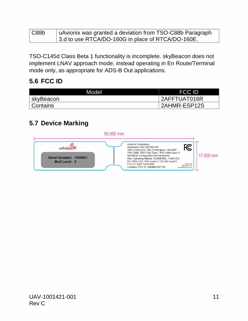
5.6 FCC ID
Model FCC ID
skyBeacon 2AFFTUAT016R
Contains 2AHMR-ESP12S
5.7 Device Marking

UAV-1001421-001 12 Rev C
5.8 Environmental Qualification Form
Conditions DO-160G
Section Description of Conducted Tests
Temperature and Altitude 4.0 Equipment tested to Category B2
Low temperature ground
survival
4.5.1 -55°C
Low Temperature Short-Time
Operating
4.5.1 -45°C
Low Temperature Operating 4.5.2 -45°C
High Temperature Operating 4.5.4 +70°C
High Temperature Short-Time
Operating
4.5.3 +70°C
High Temperature Ground
Survival
4.5.3 +85°C
Loss of Cooling 4.5.5 Cooling air not required (+70°C operating without cooling)
Altitude 4.6.1 25,000feet
Decompression 4.6.2 Equipment identified as Category B2 – no test
Overpressure 4.6.3 Equipment identified as Category B2 – no test
Temperature Variation 5.0 Equipment tested to Category A
Humidity 6.0 Equipment tested to Category C
Operation Shocks and Crash
Safety
7.0 Equipment tested to Category B
Vibration 8.0 Aircraft zone 5: type 5 (Single Engine) to Category S level M
Explosion 9.0 Equipment identified as Category H
Waterproofness 10.0 Equipment identified as Category S
Fluids Susceptibility 11.0 Equipment identified as Category F
Sand and Dust 12.0 Equipment identified as Category D
Fungus 13.0 Equipment identified as Category X – no test
Salt Spray 14.0 Equipment identified as Category S
Magnetic Field 15.0 Equipment identified as Category A
Power Input 16.0 Equipment identified as Category BX
Voltage Spike 17.0 Equipment identified as Category B
AF Conducted Susceptibility 18.0 Equipment identified as Category B
Induced Signal Susceptibility 19.0 Equipment identified as Category AC
RF Susceptibility 20.0 Equipment identified as Category T
RF Emissions 21.0 Equipment identified as Category H
Lightning Induced Transient
Susceptibility
22.0 Equipment identified as Category A2G2L2 with no loss of
function, A3G3L3 with no incorrect broadcasts
Lightning Direct Effects 23.0 Equipment identified as Category X – no test
Icing 24.0 Equipment identified as Category X – no test
Electrostatic Discharge 25.0 Equipment identified as Category A
Fire, Flammability 26.0 Equipment identified as Category C

UAV-1001421-001 13 Rev C
5.9 Continued Airworthiness
Maintenance of the skyBeacon is "on condition" only. For regulatory
periodic functional checks, refer to the approved aircraft maintenance
manuals or manual supplements. The aircraft must be returned to service
in a means acceptable to the appropriate aviation authority.
The forward position light is designed with 3 red LEDs. The anti-collision
light is designed with 4 white LEDs. If any one LED fails, the unit must be
repaired or replaced.
Note: Use dark glasses or cover the device to ensure eye safety during
LED inspection.
5.10 System Limitations
Installation
This article meets the minimum performance and quality control standards
required by a technical standard order (TSO). If you are installing this
article on or in a specific type or class of aircraft, you must obtain separate
approval for installation.
TCAS/ACAS system
skyBeacon does not support installation on aircraft with an active
TCAS/ACAS system.
SatCom
The skyBeacon GPS has not been demonstrated as compatible with
SatCom equipment and should not be installed on SatCom equipped
aircraft.
Location
skyBeacon must be installed at least 3 feet from any operating transponder
antenna.

UAV-1001421-001 14 Rev C
6 System Specifications
6.1 System Functionality
skyBeacon is a wing-tip mounted unit that contains a 978 MHz transmitter,
power line transponder monitor, GPS/SBAS receiver, barometric pressure
sensor and altitude encoder, LED position light and LED anti-collision light.
This device transmits ownship Automatic Dependent Surveillance-
Broadcast (ADS-B) data through the UAT data link. It monitors an installed
transponder for Mode A/C replies. skyBeacon includes an internal
GPS/SBAS receiver. This receiver allows the unit to function as its own
position source.
6.2 Altitude Encoder with Continuous Calibration™
The integrated altitude encoder does not require connection to the aircraft
static pressure system. Instead, skyBeacon benefits from being mounted in
an ideal altitude sensing location, and contains Continuous Calibration™
technology. This patent pending technology automatically and continuously
calibrates the integrated altitude encoder for correspondence with the
aircraft transponder’s altitude encoder, allowing compliant operations in
remote and challenging environments.
6.3 Power Line Transponder Monitor
skyBeacon utilizes uAvionix’s Power Transcoder to ensure proper
synchronization of data elements between Secondary Surveillance Radar
(SSR) replies and ADS-B transmissions. These elements include Mode A
squawk and IDENT status. In remote areas where you may not be
interrogated by SSR, these data elements may at times be unavailable.
The Power Transcoder additionally serves to provide Continuous
Calibration™ data to the altitude encoder.

UAV-1001421-001 15 Rev C
6.4 Anonymous Mode
In anonymous mode, skyBeacon transmits a randomized temporary
address instead of the aircraft’s assigned ICAO address code, and a non-
identifying Call Sign. The temporary address and Call Sign are disabled if
the operator selects a non-1200 squawk code on the transponder. When
enabled, the operator will not be eligible to receive ATC services.
Anonymous Mode must not be enabled when skyBeacon is installed in an
aircraft with a Mode S transponder. Doing so will present an ICAO code
mismatch to ATC.
6.5 Wi-Fi
Wi-Fi is intended for on-ground configuration. It is disabled five minutes
after startup, or when airborne, whichever occurs first. Connecting the
skyBeacon Installer app to the device will prevent the five minute shutdown
from occurring.
To restore Wi-Fi functionality after flight, power to the device must be
cycled.
6.6 Call Sign
Your call sign may be adjusted on the ground using the skyBeacon Installer
app. It may not be adjusted in flight. This allows your call sign to be
configured to correspond with ATC communications and flight plans, for
use during commercial, medical, or volunteer flight operations. When
changing the call sign ensure no other installation parameters are adjusted.
For typical operations, the call sign should be set to the aircraft registration
(N-number), including the leading “N”.
UAV-1001421-001 16 Rev C
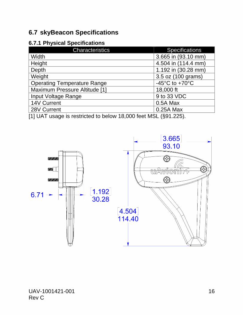
6.7 skyBeacon Specifications
6.7.1 Physical Specifications
Characteristics Specifications
Width 3.665 in (93.10 mm)
Height 4.504 in (114.4 mm)
Depth 1.192 in (30.28 mm)
Weight 3.5 oz (100 grams)
Operating Temperature Range -45°C to +70°C
Maximum Pressure Altitude [1] 18,000 ft
Input Voltage Range 9 to 33 VDC
14V Current 0.5A Max
28V Current 0.25A Max
[1] UAT usage is restricted to below 18,000 feet MSL (§91.225).

UAV-1001421-001 17 Rev C
6.7.2 GPS/SBAS Specifications
Characteristics Specifications
Number of Channels 15 (12 GPS and 3 GPS/SBAS)
Frequency 1575.42 MHz L1, C/A code
Sensitivity Tracking Reacquisition Cold Start Hot Start
-166 dBm -160 dBm -148 dBm -160 dBm
Horizontal position accuracy 6 m RMS with SBAS
Velocity accuracy 0.05 m/s
Heading accuracy 0.3 degrees
TTFF (Time to First Fix) 58 seconds typical with current almanac and position
Reacquisition 1 second typical
Position update interval 0.2 second (5 Hz)
Time Mark ±20 nSec of UTC
Datum WGS-84
6.7.3 Altitude Encoder Specifications
Characteristics Specifications
Altitude Range [1] -1,000 to 18,000 feet
[1] UAT usage is restricted to below 18,000 feet MSL (§91.225).
6.7.4 978MHz UAT Specifications
Characteristics Specifications
Frequency 978.00 MHz
Transmit Power 44 dBm (25 W)
Frequency Tolerance ±10 PPM
Modulation Continuous phase FSK, h = 0.6, raised cosine, a = 0.5
Data Rate 1.041667 Mbps
99% Power Bandwidth 1.3 MHz
60dB bandwidth 3.3 MHz

UAV-1001421-001 18 Rev C
6.7.5 System Interfaces
Position Light Breaker
Transponder
Aircraft Power
(14/28V)
YELLOW
RED
Anti-Collision Light Breaker
Aircraft Ground
BLACK
Wi-Fi iOS/
Android
Device

UAV-1001421-001 19 Rev C
7 Installation
7.1 Part Numbers
Item P/N
skyBeacon UAV-1001856-001
6-32 x 1-1/4” Screw (3) UAV-1001459-001
5mm x 1mm O-Ring (6) UAV-1002038-001
Wire Splice (3) UAV-1001487-001
7.2 Unpacking and Inspecting
Carefully unpack the device and make a visual inspection of the unit for
evidence of any damage incurred during shipment. If the unit is damaged,
notify the shipping company to file a claim for the damage. To justify your
claim, save the original shipping container and all packing materials.
7.3 Mounting
skyBeacon is a wingtip, forward, left position light. The assembly should be
mounted as far outboard on the aircraft as practical, parallel to the vertical
and horizontal centerlines of the aircraft. Ensure that when mounted, the fin
and top of the assembly are free from obstructions. skyBeacon must be
mounted with the fin pointing down to ensure proper performance. It must
be installed at least 3 feet from any operating transponder antenna.
To ensure performance of the integrated altitude encoder, the wire bundle
exiting the skyBeacon enclosure must not be further sealed. This area
functions as the static pressure sensing port.
1. Remove the existing left position light.
2. Detach the power wire(s).
3. Connect the red wire to the switched position light power wire.
4. If replacing a position light with integrated anti-collision strobe,
connect the yellow wire to the switched anti-collision power wire.
WARNING: The yellow wire must be connected directly to 14/28V
aircraft power. It must NOT be connected to a high voltage anti-
collision power supply.
!

UAV-1001421-001 20 Rev C
5. skyBeacon may be grounded to the aircraft structure via the mounting
screws. However, it may be necessary to connect the black wire to
the battery ground.
6. Mount skyBeacon using the three supplied 6-32 screws.
7. Changes to the existing position and anti-collision light circuit breaker
rating are not required.
Note: Installation of the skyBeacon must be in accordance with AC 43.13-
2B, Chapter 1
7.4 Wiring
skyBeacon is designed to use existing position and/or anti-collision light
wiring. If new wiring is required, refer to AC 43.13-1B Chapter 11 for
guidance. The wiring should present an impedance of less than 0.5ohm.
The following table provides guidance for typical aircraft hook-up wire.
Gauge ohm/km Maximum Length for 0.5ohm
20 AWG 35 14.2m
22 AWG 64 7.8m

UAV-1001421-001 21 Rev C
7.5 Unit Installation
skyBeacon is mounted with three 6-32-inch screws to the existing holes
and nut plates in the end of the wing. Two O-rings per screw must be used
between the screw and skyBeacon assembly.

UAV-1001421-001 22 Rev C
7.6 Mounting Dimensions

UAV-1001421-001 23 Rev C
8 Maintenance
The skyBeacon is not a user serviceable product. All service must be
performed either by uAvionix or an authorized uAvionix repair center.
9 Care and Cautions
The skyBeacon should be regularly cleaned with warm soapy water and a
soft cloth micro-fiber rag. Use of chemical cleaners and degreasers should
be avoided. If the skyBeacon is exposed to cleaning chemicals, you should
promptly wash off all residue.
DO NOT wax, buff, paint or attempt to polish any part of the skyBeacon
assembly. Doing so may damage the housing. Avoid any contact with
abrasive materials including scrubbing pads.
Never hit, tap on or flex the fin portion of a properly mounted skyBeacon
assembly. Doing so will cause undue stress in the assembly and could void
your warranty.
10 System Configuration
Download the “uAvionix skyBeacon Installer” app from the iOS App Store
or Google Play Store. Note: DO NOT use the “uAvionix Ping® Installer” or
“uAvionix Echo Installer” apps. The app will guide you through the
configuration process.

UAV-1001421-001 24 Rev C
10.1 Connect to skyBeacon Wi-Fi
Launch the skyBeacon Installer app and follow instructions to connect to the skyBeacon for configuration. The SSID of the skyBeacon is in the form Beacon-xxxx, for example Beacon-7782. The skyBeacon Wi-Fi connection is secure. The WPA2 passphrase is written on an inclusion in your package, and should be entered exactly as printed. WPA2 passphrases are case sensitive. Keep the inclusion containing Wi-Fi information in a safe place, preferably with your aircraft records.

UAV-1001421-001 25 Rev C
10.2 Configuration
10.2.1 Configure
The configure screen provides all configuration options.
Anonymous Mode: When checked, this enables the skyBeacon to transmit a self-assigned (random) ICAO and non-identifying Call Sign when the squawk code matches the defined VFR squawk code (1200). When enabled, the operator will not be eligible to receive ATC services. Call Sign: The CALL SIGN can be up to an 8 digit code that corresponds to the tail number of the aircraft. (0-9, A-Z). Note: This is typically your aircraft N-number (e.g. N8644B), unless otherwise advised by the FAA or ATC. ICAO Number: The ICAO address is a 24-bit number issued to the aircraft by the registration authority of the aircraft. These addresses are usually written as a 6-digit hexadecimal number. Vso (knots): This parameter allows skyBeacon to automatically switch between airborne and ground modes and should be set to the aircraft stall speed. ADS-B In Capability: Sets the ADS-B In equipment capability reporting. This is used to indicate the current aircraft configuration. Tap “Update” when complete.

UAV-1001421-001 26 Rev C
Position Light: Sets the position light on or off.
Anti-collision Light: Sets the anti-collision light on or off.
Emitter Type: To assist ATC tracking of aircraft, an aircraft category can be transmitted. Select the aircraft category that most closely matches the aircraft.
Aircraft Length: Enter the aircraft Length in Meters.
Aircraft Width: Enter the aircraft width in Meters.
GPS Antenna Offset (Lateral): Enter the position of skyBeacon relative to the center of the aircraft Roll axis in Meters.
GPS Antenna Offset (Longitudinal): Enter the position of skyBeacon relative to the nose of the aircraft in Meters. Transponder Monitor Threshold: Adjust this value only if experiencing difficulties with the transponder monitor (squawk and barometric altitude) function, and at the direction of uAvionix Support. Tap “Update” when complete.

UAV-1001421-001 27 Rev C
10.3 Post-Installation Checks
Configure skyBeacon before performing system checkouts.
Tab to the “Monitor” screen on the Installer App.
Verify that Status is listed as “OK”. Information on status annunciations described in Section 11 can be found here. Verify that the Call Sign matches your aircraft’s N-number (including the ‘N’). Verify that the ICAO number is correct as entered. Select ALT mode on the Aircraft’s transponder. In an area of known radar activity or using a ramp tester interrogate the transponder and verify that the Squawk and Pressure Altitude agree with the transponder or known pressure altitude. With the skyBeacon having a clear view of the sky, allow enough time for the GPS to acquire a fix (typically less than 2 minutes). Verify that the Latitude/Longitude and GPS Altitude agree with the known reference position.

UAV-1001421-001 28 Rev C
10.4 Post-Flight and Annual Checks
After your first flight with skyBeacon, and every 12 calendar months,
perform the following checks.
Tab to the “Monitor” screen on the Installer App.
Ensure that the “Last Calibration” field has the UTC date and time of a recent flight recorded. This indicates that Continuous Calibration™ information has updated, and that the integrated altitude encoder is synchronized with your transponder altitude encoder. If no “Last Calibration” date is listed, or does not match that of a recent flight of significant duration, your Transponder Monitor Threshold may need to be adjusted, or your transponder serviced.

UAV-1001421-001 29 Rev C
11 Normal Operation
skyBeacon must be enabled (turned ON) during all phases of flight including surface movement operations. To ensure skyBeacon is enabled, aircraft power to the position light must remain on. A red LED annunciator is on the pilot facing side of the fin. It indicates operating status of the skyBeacon.
LED Indication Meaning
On (Constant) Device Failure Internal self-test failure Invalid ICAO configured
Blinking (On/off every second)
Function Failure No GPS signal ADS-B broadcast failure
Off No Failure
12 Support
For additional questions or support please visit:
https://www.uavionix.com/support/