tahiti condensing - portsdean technical files/ist tahiti... · fondital tahiti condensing 24 kw ......
TRANSCRIPT
IST 03 C 000- 01
INSTALLATION,USE AND MAINTENANCE
TAHITI CONDENSING
GB
Gas fired wall Mounted condensing boilerTahiti Condensing 24, 28, 32 kW Combi (KC)
Tahiti Condensing 24, 28, 32 kW Regular (KR)
Hig
h q
ualit
y It
alia
n p
rod
uct
MADE IN ITALY
�
Natural Gas
Fondital Tahiti Condensing 24 kW Combi (KC)G.C.N° 47 309 01
Fondital Tahiti Condensing 28 kW Combi (KC)G.C.N° 47 309 0�
Fondital Tahiti Condensing 32 kW Combi (KC)G.C.N° 47 309 03
Fondital Tahiti Condensing 24 kW Regular (KR)G.C.N° 41 309 01
Fondital Tahiti Condensing 28 kW Regular (KR)G.C.N° 41 309 0�
Fondital Tahiti Condensing 32 kW Regular (KR)G.C.N° 41 309 03
Benchmark places responsibilities on both manufacturers and installers. The purpose is to ensure that customers are provided with the correct equipment for their needs, that it is installed, commissioned and serviced in accordance with the manufacturer’s instructions by competent persons and that it meets the requirements of the appropriate Building Regulations. The Benchmark Checklist can be used to demonstrate compliance with Building Regulations and should be provided to the customer for future reference.
Installers are required to carry out installation, commissioning and servicing work in accordance with the Benchmark Code of Practice which is available from the Heating and Hotwater Industry Council who manage and promote the Scheme.Visit www.centralheating.co.uk for more information.

3
Dear Customer,Thank You for choosing and buying one of our boilers.Please read these instructions carefully in order to properly install, operate, and maintain the equipment.
4
1. General information for fitters, maintenance technicians and users
1.1. General warnings
This INSTRUCTION MANUAL, which is an integral and indispensable part of the product, must be handed over to the user by the in-staller and must be kept in a safe place for future reference. The manual must accompany the boiler should it be sold or its possession transferred. Following to the boiler installation, the fitter is to advise the user about boiler operation and its safety devices. This Manual must be left along with the Benchmark commissioning booklet with the boiler as Regulation �9 of the HSC Gas safety (installation and use) Regulations 1998.
This boiler is designed for connection to a domestic heating or hot water system. Any other use is deemed as improper and as such dangerous. Under no circumstances will the manufacturer be held responsible for damage or injury to persons or animals caused by errors in the installation and/or use of the appliance, or through non-compliance with current local and national standards and/or the manufacturer’s instructions.
The boiler must be installed by qualified personnel, in compliance with applicable laws and standards and according to the manufacturer’s instructions given in this manual.
In GB, the installation must be carried out by a Registered Installer. To check for authorised qualified engineers please contact CORGI 01�56 37�400. It must be carried out in accordance with the relevant requirements of the:
• Gas Safety Regulations;• The appropriate Building Regulations either The Building Regulation, The Building Regulations (Scotland), Building Regulations (Northern Ireland);• The Water Fittings Regulations or Water Bylaws in Scotland;• The current I.E.E. Wiring Regulations.
Where no specific instructions are given, reference should be made to the relevant British Standards Code of Practice.In IE, the installation must be carried out by a competent Person and installed in accordance with the current edition of I.E. 813 “Domestic Gas Installations”, the current Building Regulations and reference should be made to the current ETCI rules for electrical installations.
The commissioning of the boiler and any subsequent works carried out on the appliance must be effected by an appropriately qualified technician or an approved Fondital Helpline Service Centre.
Damage and/or injury caused by incorrect installation or use and/or damage and/or injury due to non-observance of the manufacturer’s instructions shall relieve the manufacturer from any and all contractual and extra-contractual liability.
Before installing the boiler, check that the technical data correspond to the requirements for its correct use in the system.
Check that the boiler is intact and it has not been damaged during transport and handling: do not install equipment which is damaged and/or faulty. In case of doubt, do not attempt to use the product but refer to the supplier. Packing materials (cardboard box, wooden crate, nails, staples, plastic bags, polystyrene, etc.) must not be left within reach of children in that these items represent a potential hazard and must be disposed of in a responsible manner.
Do not obstruct the air intake or flue exhaust grills and terminals.
Only manufacturer approved and supplied accessories or optional kits (including electric ones) are to be installed.
Properly dispose of the packaging as all the materials can be recycled. The packaging must therefore be sent to specific waste management sites.
In the event of failure and/or malfunction, shut down the system. Do not interfere with or attempt any repairs. Call for professionally qualified technical assistance only. Fondital helpline UK 08700 34 88�0.
Any warranty repairs to the appliance must be carried out exclusively by the manufacturer’s authorised service centre using original spare parts. Non-observance of the above requirements may affect the safety of the boilers and endanger people, animals and property.
The manufacturer, in order to guarantee efficient and correct functioning of the equipment, recommends the boiler to be serviced and repaired by an authorized Service Centre which is best trained for the purpose.
Before carrying out any cleaning or maintenance operations, disconnect the appliance from the mains electricity supply by switching off at the main switch and/or any other isolating device.
Routine boiler maintenance is to be performed according to the schedule indicated in the relevant section of this manual. Appropriate boiler maintenance ensures efficient operation, environment preservation, and safety for people, animals and objects.
In the event of long periods of inactivity of the boiler, disconnect it from power mains and close the gas tap. Warning!When power mains are disconnected, boiler electronic anti-freeze function will not be operative.
Should there be a risk of freezing, add anti-freeze: it is not advisable to empty the system as this may result in damage; use specific anti-freeze products suitable for multi-metal heating systems.
5
Should you smell gas: - do not turn on or off electric switches and do not turn on electric appliances; - do not ignite flames and do not smoke; - close the main gas tap; - open doors and windows; - contact a Service Centre, a qualified installer or the gas supply company. Never use flames to detect gas leaks. TRANSCO GAS EMERGENCY 0800 111 999
The boiler is designed for installation in the country indicated on the technical data plate: installation in any other country may be source of danger for people, animals and objects.
The “operating instructions” of this manual must be read carefully as it provides information on the operating and the operating limits of the appliance.
This appliance must be used exclusively in an un-vented central heating system.
The warnings contained in this chapter have been written for the appliance user, the installer and the service engineer.
1.2. Product conformity
FONDITAL S.p.a. declare that all its products are manufactured to a high specification and in compliace with the relevant standards.
All FONDITAL boilers are CE certified and possess technical and functional characteristics that comply with the following standards:
UNI EN �97 for GAS-FIRED CENTRAL HEATING BOILERS TYPE B OF NOMINAL HEAT INPUT ≤ 70 kW
EN 483 for GAS-FIRED CENTRAL HEATING BOILERS TYPE C OF NOMINAL HEAT INPUT ≤ 70 kW
UNI EN 677 for GAS-Fired CENTRAL HEATING BOILERS. SPECIFIC REQUIREMENTS FOR CONDENSING BOILERS WITH NOMINAL HEAT INPUT ≤ 70 kW
Gas fired boilers also comply with the following directives:
GAS APPLIANCES DIRECTIVE 90/396 CEE for CE compliance
LOW VOLTAGE DIRECTIVE �006/95 CE
BOILER EFFICIENCY DIRECTIVE 9�/4� CE
ELECTROMAGNETIC COMPATIBILITY DIRECTIVE 89/336 CE
The materials used such a copper, brass, stainless steel, etc. form a compact, homogeneous, highly functional unit that is easy to install and simple to operate. In its simplicity, the wall-mounted appliance is equipped with all the appropriate accessories required to make it a fully independent boiler capable of satisfying domestic hot water production and central heating needs. All boilers are fully inspected and are accompanied by a quality certificate, signed by the inspector, and a guarantee certificate. This manual must be kept in a safe place and must accompany the boiler at all times.
FONDITAL S.p.a. will not be held responsible for any misinterpretation of this manual resulting from the inaccurate translation of same.
FONDITAL S.p.a. will not be held responsible for the consequences in the case of non observance of the instructions contained in this manual or in the case where actions not specifically described herein are undertaken.
FONDITAL S.p.a. declare that no substances harmful to health are contained in the appliance or used during appliance manufacture and have not used or intend to use any of the following substances in the manufacture of Fondital heating products:- Asbestos- Mercury- CFC’s
It is a condition of the manufacturers warranty that the Benchmark Commissioning Checklist is fully completed and left with the appliance.
6
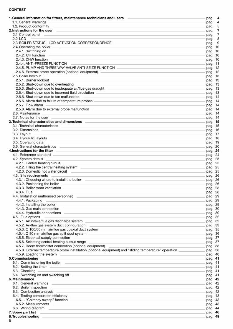
CONTEST 1. General information for fitters, maintenance technicians and users pag. 4 1.1. General warnings pag. 4 1.�. Product conformity pag. 52. Instructions for the user pag. 7 �.1 Control panel pag. 7 �.� LCD pag. 8 �.3 BOILER STATUS - LCD ACTIVATION CORRESPONDENCE pag. 9 �.4 Operating the boiler pag. 10 �.4.1. Switching on pag. 10 �.4.�. CH function pag. 10 �.4.3. DHW function pag. 10 �.4.4. ANTI-FREEZE FUNCTION pag. 11 �.4.5. PUMP AND THREE WAY VALVE ANTI-SEIZE FUNCTION pag. 1� �.4.6. External probe operation (optional equipment) pag. 1� �.5. Boiler lockout pag. 13 �.5.1. Burner lockout pag. 13 �.5.�. Shut-down due to overheating pag. 13 �.5.3. Shut-down due to inadequate air/flue gas draught pag. 13 �.5.4. Shut-down due to incorrect fluid circulation pag. 13 �.5.5. Shut-down due to fan malfunction pag. 14 �.5.6. Alarm due to failure of temperature probes pag. 14 �.5.7 Flow alarm pag. 14 �.5.8. Alarm due to external probe malfunction pag. 14 �.6. Maintenance pag. 14 �.7. Notes for the user pag. 143. Technical characteristics and dimensions pag. 15 3.1. Technical characteristics pag. 15 3.�. Dimensions pag. 16 3.3. Layout pag. 17 3.4. Hydraulic layouts pag. 18 3.5. Operating data pag. 19 3.6. General characteristics pag. �04. Instructions for the fitter pag. 24 4.1. Reference standard pag. �4 4.�. System details pag. �5 4.�.1. Central heating circuit pag. �5 4.�.�. Filling the central heating system pag. �5 4.�.3. Domestic hot water circuit pag. �5 4.3. Site requirements pag. �6 4.3.1. Choosing where to install the boiler pag. �6 4.3.�. Positioning the boiler pag. �6 4.3.3. Boiler room ventilation pag. �8 4.3.4. Flue pag. �8 4.4. Installation (authorised personnel) pag. �9 4.4.1. Packaging pag. �9 4.4.�. Installing the boiler pag. �9 4.4.3. Gas main connection pag. 30 4.4.4. Hydraulic connections pag. 30 4.5. Flue options pag. 3� 4.5.1. Air intake/flue gas discharge system pag. 3� 4.5.�. Air/flue gas system duct configuration pag. 33 4.5.3. Ø 100/60 mm air/flue gas coaxial duct system pag. 35 4.5.4. Ø 80 mm air/flue gas split duct system pag. 36 4.5.5. Electrical supply connection pag. 37 4.5.6. Selecting central heating output range pag. 37 4.5.7. Room thermostat connection (optional equipment) pag. 38 4.5.8. External temperature probe installation (optional equipment) and “sliding temperature” operation pag. 38 4.5.9. Loading the system pag. 405. Commissioning pag. 41 5.1. Commissioning the boiler pag. 41 5.�. Setting the timer pag. 41 5.3. Checking pag. 41 5.4. Switching on and switching off pag. 416. Maintenance pag. 42 6.1. General warnings pag. 4� 6.�. Boiler inspection pag. 4� 6.3. Combustion analysis pag. 4� 6.4. Testing combustion efficiency pag. 43 6.5.1. “Chimney sweep” function pag. 43 6.5.�. Measurements pag. 43 6.6. Wiring diagram pag. 447. Spare part list pag. 468. Troubleshooting pag. 49
7
2. Instructions for the user
Fondital is a licensed member of the Benchmark Scheme which aims to improve the standards of installation and commissioning of domestic heating and hot water systems in the UK and to encourage regular servicing to optimise safety, efficiency and performance.
Benchmark is managed and promoted by the Heating and Hotwater Industry Council. For more information visit www.centralheating.co.uk
Please ensure that the installer has fully completed the Benchmark Checklist on the inside back pages of the installation instructions supplied with the product and that you have signed it to say that you have received a full and clear explanation of its operation. The installer is legally required to complete a commissioning checklist as a means of complying with the appropriate Building Regulations (England and Wales).
All installations must be notified to Local Area Building Control either directly or through a Competent Persons Scheme. A Building Regu-lations Compliace Certificate will then be issued to the customer who should, on receipt, write the Notification Number on the Bench-mark Checklist.
This product should be serviced regularly to optimise its safety, efficiency and performance. The service engineer should complete the relevant Service Record on the Benchmark Checklist after each service.
The Benchmark Checklist may be required in the event of any warranty work and as supporting documentation relating to home im-
provements in the optional documents section of the Home Information Pack.
2.1. Control panel
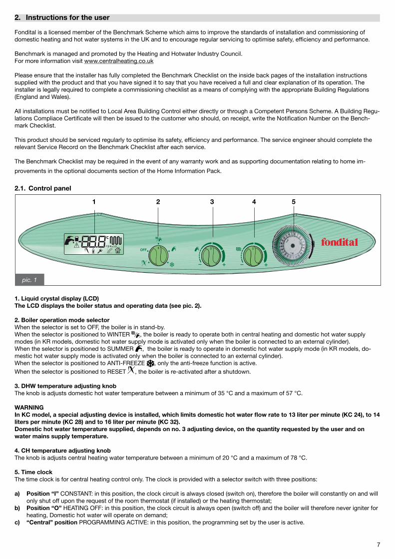
1. Liquid crystal display (LCD)The LCD displays the boiler status and operating data (see pic. 2).
2. Boiler operation mode selectorWhen the selector is set to OFF, the boiler is in stand-by.When the selector is positioned to WINTER , the boiler is ready to operate both in central heating and domestic hot water supply modes (in KR models, domestic hot water supply mode is activated only when the boiler is connected to an external cylinder).When the selector is positioned to SUMMER , the boiler is ready to operate in domestic hot water supply mode (in KR models, do-mestic hot water supply mode is activated only when the boiler is connected to an external cylinder).When the selector is positioned to ANTI-FREEZE , only the anti-freeze function is active.When the selector is positioned to RESET , the boiler is re-activated after a shutdown.
3. DHW temperature adjusting knobThe knob is adjusts domestic hot water temperature between a minimum of 35 °C and a maximum of 57 °C.
WARNINGIn KC model, a special adjusting device is installed, which limits domestic hot water flow rate to 13 liter per minute (KC 24), to 14 liters per minute (KC 28) and to 16 liter per minute (KC 32).Domestic hot water temperature supplied, depends on no. 3 adjusting device, on the quantity requested by the user and on water mains supply temperature.
4. CH temperature adjusting knobThe knob is adjusts central heating water temperature between a minimum of �0 °C and a maximum of 78 °C.
5. Time clockThe time clock is for central heating control only. The clock is provided with a selector switch with three positions:
a) Position “I” CONSTANT: in this position, the clock circuit is always closed (switch on), therefore the boiler will constantly on and will only shut off upon the request of the room thermostat (if installed) or the heating thermostat;b) Position “O” HEATING OFF: in this position, the clock circuit is always open (switch off) and the boiler will therefore never igniter for heating, Domestic hot water will operate on demand;c) “Central” position PROGRAMMING ACTIVE: in this position, the programming set by the user is active.
pic. 1
5 1 2 4 3
8
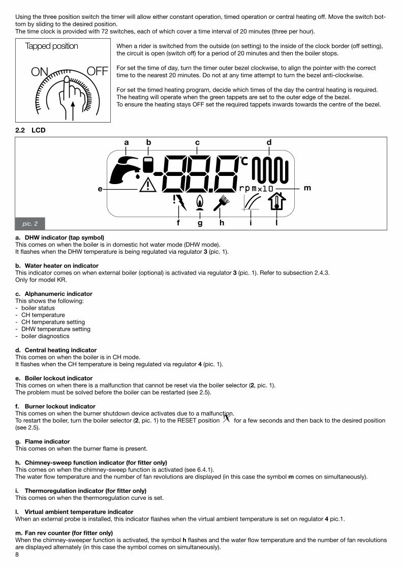
2.2 LCD
a. DHW indicator (tap symbol)This comes on when the boiler is in domestic hot water mode (DHW mode).It flashes when the DHW temperature is being regulated via regulator 3 (pic. 1).
b. Water heater on indicatorThis indicator comes on when external boiler (optional) is activated via regulator 3 (pic. 1). Refer to subsection �.4.3.Only for model KR.
c. Alphanumeric indicatorThis shows the following:- boiler status- CH temperature- CH temperature setting- DHW temperature setting- boiler diagnostics
d. Central heating indicatorThis comes on when the boiler is in CH mode.It flashes when the CH temperature is being regulated via regulator 4 (pic. 1).
e. Boiler lockout indicatorThis comes on when there is a malfunction that cannot be reset via the boiler selector (2, pic. 1).The problem must be solved before the boiler can be restarted (see �.5).
f. Burner lockout indicatorThis comes on when the burner shutdown device activates due to a malfunction. To restart the boiler, turn the boiler selector (2, pic. 1) to the RESET position for a few seconds and then back to the desired position (see �.5).
g. Flame indicatorThis comes on when the burner flame is present.
h. Chimney-sweep function indicator (for fitter only)This comes on when the chimney-sweep function is activated (see 6.4.1).The water flow temperature and the number of fan revolutions are displayed (in this case the symbol m comes on simultaneously).
i. Thermoregulation indicator (for fitter only)This comes on when the thermoregulation curve is set.
l. Virtual ambient temperature indicatorWhen an external probe is installed, this indicator flashes when the virtual ambient temperature is set on regulator 4 pic.1.
m. Fan rev counter (for fitter only) When the chimney-sweeper function is activated, the symbol h flashes and the water flow temperature and the number of fan revolutions are displayed alternately (in this case the symbol comes on simultaneously).
pic. 2
a b c d
e
f g h i l
m
Using the three position switch the timer will allow either constant operation, timed operation or central heating off. Move the switch bot-tom by sliding to the desired position.The time clock is provided with 7� switches, each of which cover a time interval of �0 minutes (three per hour).
When a rider is switched from the outside (on setting) to the inside of the clock border (off setting), the circuit is open (switch off) for a period of �0 minutes and then the boiler stops.
For set the time of day, turn the timer outer bezel clockwise, to align the pointer with the correct time to the nearest �0 minutes. Do not at any time attempt to turn the bezel anti-clockwise.
For set the timed heating program, decide which times of the day the central heating is required. The heating will operate when the green tappets are set to the outer edge of the bezel.To ensure the heating stays OFF set the required tappets inwards towards the centre of the bezel.
ON OFF
Tapped position
9
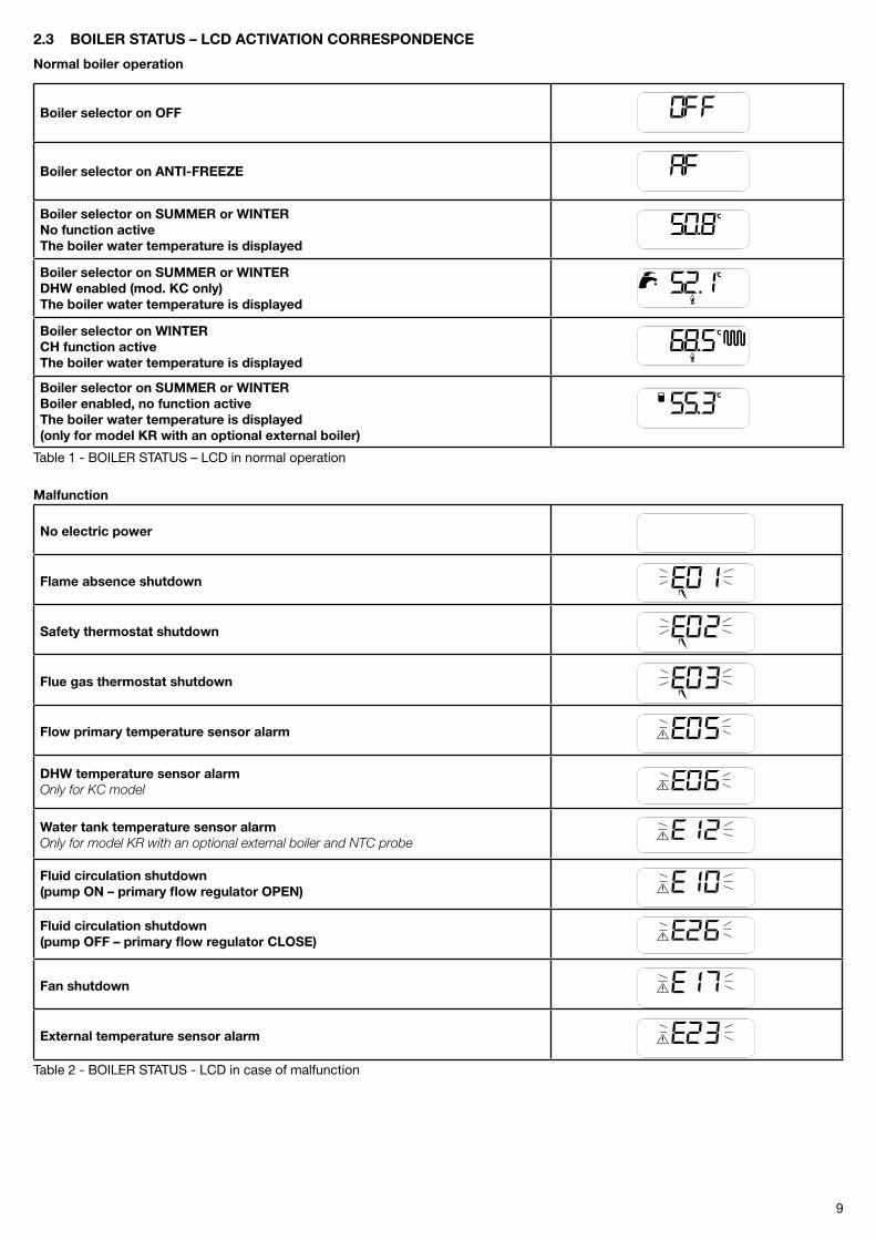
2.3 BOILER STATUS – LCD ACTIVATION CORRESPONDENCE
Normal boiler operation
Boiler selector on OFF
Boiler selector on ANTI-FREEZE
Boiler selector on SUMMER or WINTERNo function activeThe boiler water temperature is displayed
Boiler selector on SUMMER or WINTERDHW enabled (mod. KC only)The boiler water temperature is displayed
Boiler selector on WINTERCH function activeThe boiler water temperature is displayed
Boiler selector on SUMMER or WINTERBoiler enabled, no function activeThe boiler water temperature is displayed (only for model KR with an optional external boiler)
Table 1 - BOILER STATUS – LCD in normal operation
Malfunction
No electric power
Flame absence shutdown
Safety thermostat shutdown
Flue gas thermostat shutdown
Flow primary temperature sensor alarm
DHW temperature sensor alarmOnly for KC model
Water tank temperature sensor alarmOnly for model KR with an optional external boiler and NTC probe
Fluid circulation shutdown (pump ON – primary flow regulator OPEN)
Fluid circulation shutdown(pump OFF – primary flow regulator CLOSE)
Fan shutdown
External temperature sensor alarm
Table � - BOILER STATUS - LCD in case of malfunction
10
2.4 Operating the boiler
2.4.1 Switching on
The following procedure is to be implemented only after the boiler is installed and tested by a qualified fitter.
- Open the gas stop cock;- turn ON the power switch external to the boiler: LCD shows the current active function (see tables 1 and �);- select boiler operation mode via no. 2 selector (pic. 1);- set desired CH temperature (see �.4.�. paragraph);- set desired DHW (see �.4.3. paragraph);- set desired room temperature by means of the room thermostat in the premises (when available).
WARNINGShould the boiler be left inactive for a long time, particularly when boiler is LPG fired, ignition might be difficult. Before starting the boiler switch on another gas powered device (e.g. kitchen range).Beware that even by following this procedure, the boiler might still experience some starting difficulties and shut down once or twice. Resume boiler operation by turning no. 2 knob to the reset position for two seconds and back to the desired position. Allow three minutes between each attempt to re-light the boiler.
2.4.2 CH function
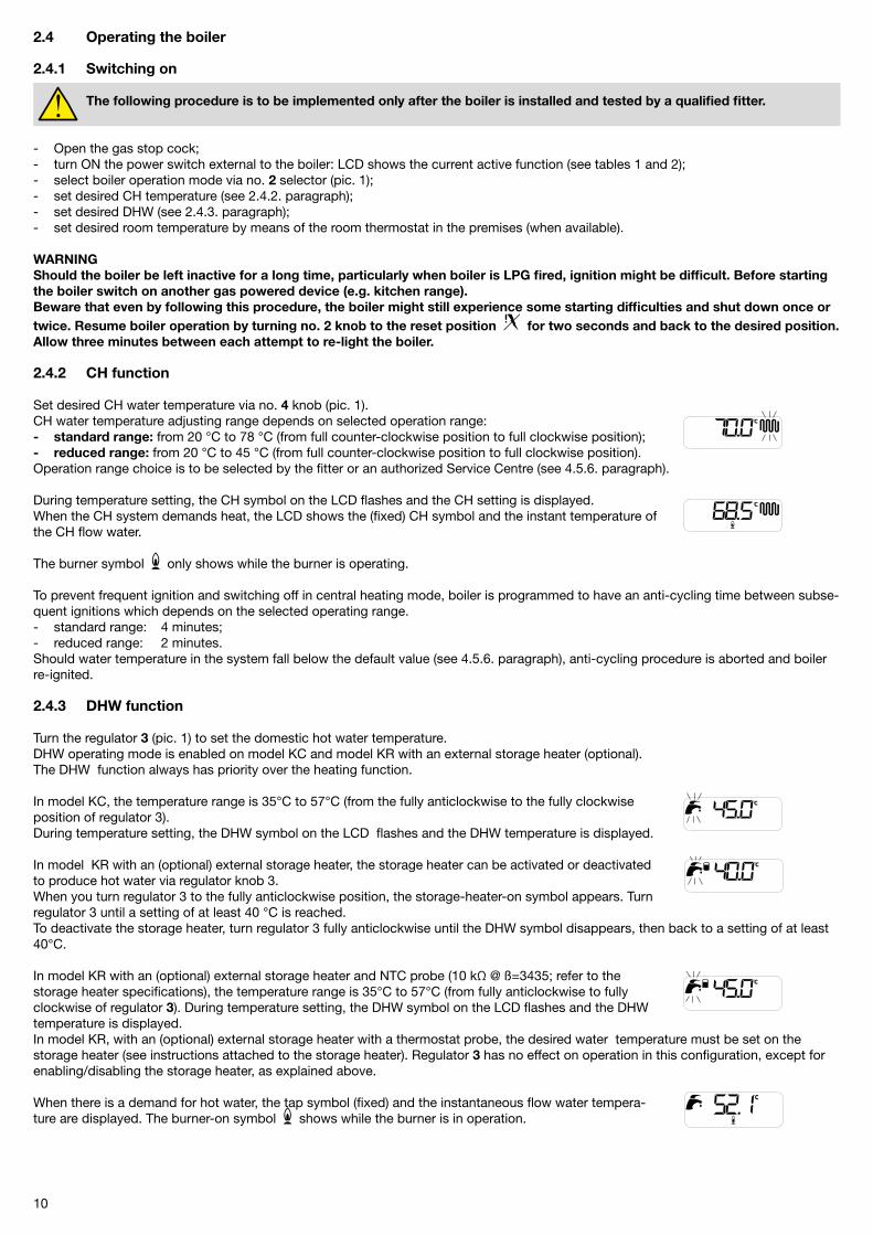
Set desired CH water temperature via no. 4 knob (pic. 1).CH water temperature adjusting range depends on selected operation range:- standard range: from �0 °C to 78 °C (from full counter-clockwise position to full clockwise position);- reduced range: from �0 °C to 45 °C (from full counter-clockwise position to full clockwise position).Operation range choice is to be selected by the fitter or an authorized Service Centre (see 4.5.6. paragraph).
During temperature setting, the CH symbol on the LCD flashes and the CH setting is displayed.When the CH system demands heat, the LCD shows the (fixed) CH symbol and the instant temperature of the CH flow water.
The burner symbol only shows while the burner is operating.
To prevent frequent ignition and switching off in central heating mode, boiler is programmed to have an anti-cycling time between subse-quent ignitions which depends on the selected operating range.- standard range: 4 minutes;- reduced range: � minutes.Should water temperature in the system fall below the default value (see 4.5.6. paragraph), anti-cycling procedure is aborted and boiler re-ignited.
2.4.3 DHW function
Turn the regulator 3 (pic. 1) to set the domestic hot water temperature. DHW operating mode is enabled on model KC and model KR with an external storage heater (optional). The DHW function always has priority over the heating function.
In model KC, the temperature range is 35°C to 57°C (from the fully anticlockwise to the fully clockwise position of regulator 3).During temperature setting, the DHW symbol on the LCD flashes and the DHW temperature is displayed.
In model KR with an (optional) external storage heater, the storage heater can be activated or deactivated to produce hot water via regulator knob 3.When you turn regulator 3 to the fully anticlockwise position, the storage-heater-on symbol appears. Turn regulator 3 until a setting of at least 40 °C is reached.To deactivate the storage heater, turn regulator 3 fully anticlockwise until the DHW symbol disappears, then back to a setting of at least 40°C.
In model KR with an (optional) external storage heater and NTC probe (10 kΩ @ ß=3435; refer to the storage heater specifications), the temperature range is 35°C to 57°C (from fully anticlockwise to fully clockwise of regulator 3). During temperature setting, the DHW symbol on the LCD flashes and the DHW temperature is displayed. In model KR, with an (optional) external storage heater with a thermostat probe, the desired water temperature must be set on the storage heater (see instructions attached to the storage heater). Regulator 3 has no effect on operation in this configuration, except for enabling/disabling the storage heater, as explained above.
When there is a demand for hot water, the tap symbol (fixed) and the instantaneous flow water tempera-ture are displayed. The burner-on symbol shows while the burner is in operation.

11
WARNINGIn KC model, a special adjusting device is installed, which limits domestic hot water flow rate to 13 liter per minute (KC 24), to 14 liters per minute (KC 28) and to 16 liter per minute (KC 32).Domestic hot water temperature supplied, depends on no. 3 DHW thermostat, on the quantity requested by the user and on water mains supply temperature.
In KC model, DHW liter per minute flow depends on the boiler’s thermal capacity and water mains supply temperature, according to the following formula:
Kl = DHW liter per minute = -------- ΔT
K represents:- 401 in KC �4 model- 444 in KC �8 model- 507 in KC 3� model
ΔT = DHW temperature – water mains supply temperature
E.g. in KC model, when water mains supply temperature is 8 °C and DHW is required to be 38 °C, in order to have a shower, the value of ΔT is:
ΔT = 38 °C – 8 °C = 30 °C
and DHW liters (l per minute) available at the required temperature of 8 °C are:
I = 401/30 = 13.4 [liter per minute] (mixed water at the tap).
In contrast, in KR model equipped with an external cylinder (optional equipment), available DHW flow depends on the cylinder capacity.
In KR model with external cylinder (optional equipment), every 15 days, the anti-Legionella function is activated. It consists in heating up the cylinder to 65 °C for 30 minutes; regardless of boiler mode setting.
2.4.4 ANTI-FREEZE FUNCTION
The boiler is equipped with anti-freeze function, which is active in SUMMER, WINTER and ANTI-FREEZE modes.
Anti-freeze function protects the boiler only and not the whole central heating system. Central heating system is to be protected by means of an ambient thermostat, although this is disabled when the boiler is set to the ANTI-FREEZE and OFF modes. Should anti-freeze protection be necessary for the boiler and CH system, select WINTER position through no. 2 knob.
When central heating water temperature sensor detects a water temperature of 5 °C, the boiler is switched on and stays on at minimum heat output until central heating water temperature reaches 30 °C or 15 minutes have elapsed.Should boiler shut down, pump operation is still granted.
In KC model, anti-freeze function protects the domestic hot water system as well.When domestic hot water probe detects a temperature of 5 °C, the boiler ignites and stays on at minimum heat output until domestic hot water temperature reaches 10 °C or 15 minutes have elapsed (the deviating valve is set to domestic hot water position).Should boiler shut down, pump operation is still granted.
In CH only boilers equipped with a DHW supply external cylinder, anti-freeze function protects the cylinder as well.The function is active only for cylinders equipped with 10 kΩ @ ß=3435 type NTC probe (refer to cylinder technical data).When cylinder water temperature probe detects a water temperature of 5 °C, the boiler is switched on and stays on at minimum heat output until cylinder water temperature reaches 10 °C or 15 minutes have elapsed (the deviating valve is set to domestic hot water position).Should the boiler shut down, pump operation is granted.
In model KR, with an (optional) external storage heater for the production of domestic hot water, which incorporates a temperate sensor similar to a thermostat, the anti-freeze function DOES NOT protect the storage heater.In this case the storage heater is protected by setting the boiler to SUMMER or WINTER (via selector �), by enabling the storage heater (via regulator 3) as detailed in the previous subsection, and by selecting a temperature on the thermostat above 0°C.
CH system can be effectively protected from freezing by means of specific anti-freezing addictives suitable in multi-metal systems.Do not use automotive anti-freeze products, and periodically check anti-freeze product effectiveness.
1�
pic. 3
15 35
32
25
18
2.4.5 PUMP AND THREE-WAY VALVE ANTI-SEIZE FUNCTION
Where the boiler is to remain inactive and:- no. 2 selector is not set to the OFF position;- boiler is not disconnected from electric main power supply;the circulation pump (KC and KR model) and three-way valve (KC model), are operated for 30 second every �4 hours in order to prevent the components from seizing.
2.4.6 External probe operation (optional equipment)
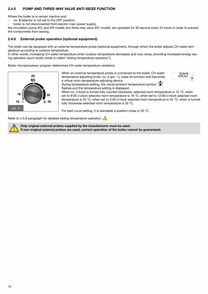
The boiler can be equipped with an external temperature probe (optional equipment), through which the boiler adjusts CH water tem-perature according to outdoor temperature.In other words, increasing CH water temperature when outdoor temperature decreases and vice-versa, providing increased energy sav-ing operation (such boiler mode is called “sliding temperature operation”).
Boiler microprocessor program determines CH water temperature variations.
When an external temperature probe is connected to the boiler, CH water temperature adjusting knob, no. 4 (pic. 1), loses its function and becomes a virtual room temperature adjusting device.During temperature setting, the virtual ambient temperature symbol flashes and the temperature setting is displayed.When no. 4 knob is turned fully counter-clockwise, selected room temperature is 15 °C; when set to 9:00 o’clock selected room temperature is 18 °C; when set to 1�:00 o’clock selected room temperature is �5 °C; when set to 3:00 o’clock selected room temperature is 3� °C; when is turned fully clockwise selected room temperature is 35 °C.
For best curve setting, it is advisable a position close to �0 °C.
Refer to 4.5.8 paragraph for detailed sliding temperature operation.
Only original external probes supplied by the manufacturer must be used. If non-original external probes are used, correct operation of the boiler cannot be guaranteed.
13
fig. 4Water pressure gauge
2.5 Boiler lockout
Should any malfunction occur, boiler automatically shuts down. Refer to no. 1 and no. � charts for boiler status detection.In order to detect the probable malfunction causes, see, in addition to no. � chart, no. 8 “Troubleshooting” paragraph at the end of the manual, as well.Follow the described procedure with respect to the type of lockout.
2.5.1 Burner lockout
If the burner shuts down as there is no flame, the burner shutdown symbol is displayed and code E01 flashes.Should this happen proceed as follows:- check the gas stopcock to be open, and gas network is actually providing service, by lighting a gas powered kitchen appliance such as a kitchen range or oven;- once gas presence is verified, reset the burner by turning no. 2 knob (pic. 1) to the reset position for two seconds, and then to the desired mode position: should the boiler not start shut down, and after performing three reset procedures, contact the Fondital helpline UK.
Should frequent burner lockout occur, a recurrent malfunction might be present: contact the Fondital helpline UK or qualified personnel for service.
2.5.2 Shut-down due to overheating
When CH flow water overheats the boiler is shut down, the burner shutdown symbol is displayed and code E0� flashes.Should the above happen contact the Fondital helpline UK or CORGI registered engineer with appropriate competence for service.
2.5.3 Shut-down due to inadequate air/flue gas draught
Should the boiler shut down due to air intake and/or flue gas discharge ducts malfunction, the burner shutdown symbol is displayed and code E03 flashes (intervention of flue gas thermostats).Should the above happen contact the Fondital helpline UK or CORGI registered engineer with appropriate competence for service.
2.5.4 Shut-down due to incorrect fluid circulation
Should CH water circulation not be adequate, the boiler is shut-down.The boiler shutdown symbol is displayed and codes E10 or E�6 flash, depending on the boiler function.
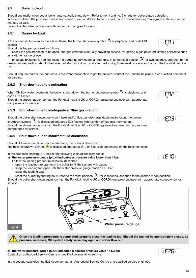
In the first case (flashing E10 code), the following � situations may occur:a) the water pressure gauge (pic.4) indicates a pressure value lower than 1 bar Follow the loading procedure as below described: - open the loading tap upstream the boiler to fill the system with water; - keep the loading tap open until the water pressure gauge reads 1÷1.3 bar; - close the loading tap; - reset the burner by turning no. 2 knob to the reset position for � seconds, and then to the desired mode position.Should the boiler shut down again, contact the Fondital helpline UK or CORGI registered engineer with appropriate competence for service.
Once the loading procedure is completed, properly close the loading tap. Should the tap not be appropriately closed, as pressure increases, CH system safety valve may open and water flow out.
b) the water pressure gauge (pic.4) indicates a correct pressure value 1÷1.3 barContact an authorized Service Centre or qualified personnel for service.
In the second case (flashing E�6 code) contact an Authorised Service Centre or a qualified service engineer.
14
2.5.5 Shut-down due to fan malfunction
Fan operation is constantly monitored and in case of malfunction the burner is turned off and the LCD shows the boiler shutdown symbol with flashing E17 code. The above status continues until correct fan operation is restored. Should the boiler not re-start and still remain in the above status, contact the Fondital helpline UK or CORGI registered engineer with appropri-ate competence for service.
2.5.6 Alarm due to failure of temperature probes
Should the temperature probes malfunction, the boiler shutdown symbol is displayed and the following codes may flash: - E05, CH probe: the boiler does not.- E06, DHW probe (only KC model): the boiler only operates in CH mode, not DHW mode.- E1�, storage probe (only KR model with optional external boiler and NTC temperature probe: 10 kΩ @ ß=3435): the boiler operates in CH, while DHW production is disabled.Contact the Fondital helpline UK 08700 34 88 �0 or CORGI registered engineer with appropriate competence for service.
2.5.7 Flow alarm
Should flow temperature rise above 85 °C, the burner is turned off.Normal boiler operation will be restored once flow temperature decreases below 85 °C.
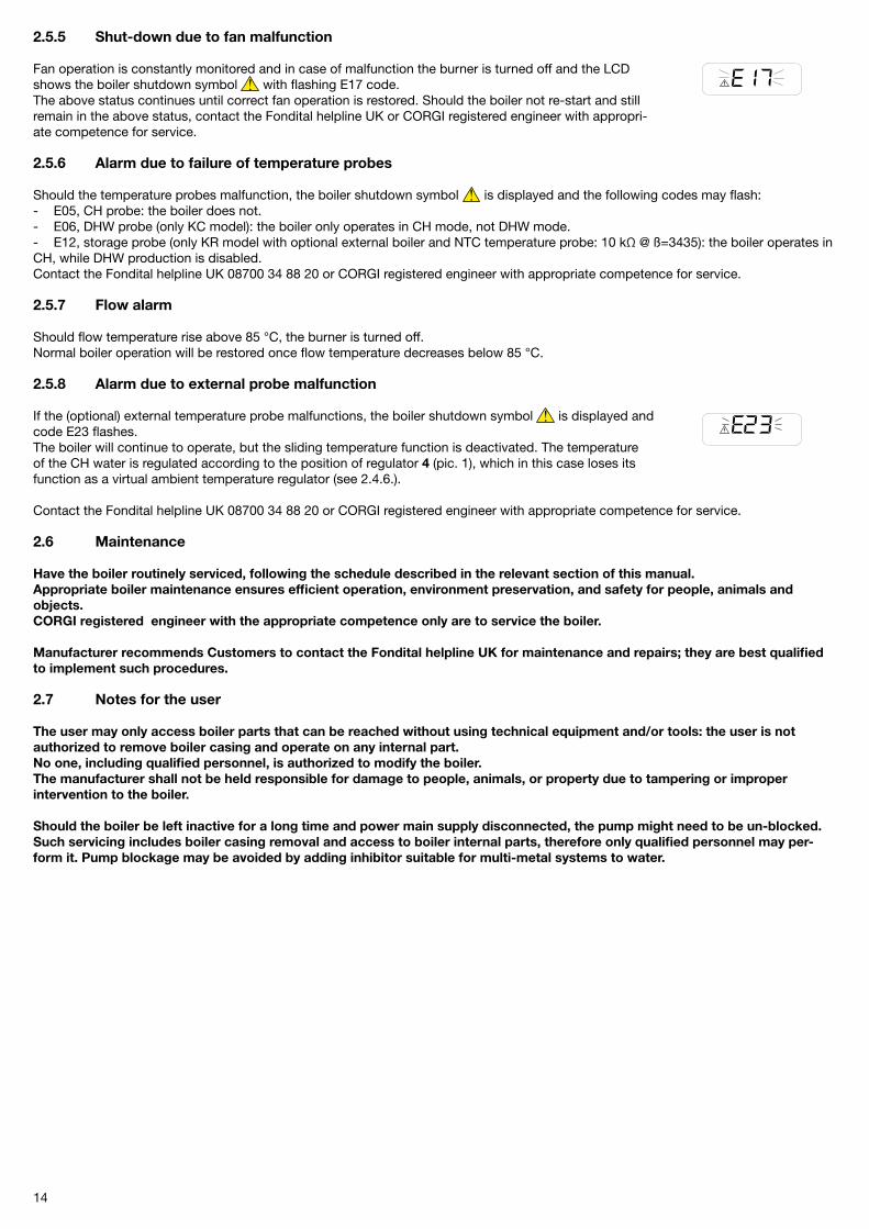
2.5.8 Alarm due to external probe malfunction
If the (optional) external temperature probe malfunctions, the boiler shutdown symbol is displayed and code E�3 flashes. The boiler will continue to operate, but the sliding temperature function is deactivated. The temperature of the CH water is regulated according to the position of regulator 4 (pic. 1), which in this case loses its function as a virtual ambient temperature regulator (see �.4.6.).
Contact the Fondital helpline UK 08700 34 88 �0 or CORGI registered engineer with appropriate competence for service.
2.6 Maintenance
Have the boiler routinely serviced, following the schedule described in the relevant section of this manual.Appropriate boiler maintenance ensures efficient operation, environment preservation, and safety for people, animals and objects.CORGI registered engineer with the appropriate competence only are to service the boiler.
Manufacturer recommends Customers to contact the Fondital helpline UK for maintenance and repairs; they are best qualified to implement such procedures.
2.7 Notes for the user
The user may only access boiler parts that can be reached without using technical equipment and/or tools: the user is not authorized to remove boiler casing and operate on any internal part.No one, including qualified personnel, is authorized to modify the boiler.The manufacturer shall not be held responsible for damage to people, animals, or property due to tampering or improper intervention to the boiler.
Should the boiler be left inactive for a long time and power main supply disconnected, the pump might need to be un-blocked.Such servicing includes boiler casing removal and access to boiler internal parts, therefore only qualified personnel may per-form it. Pump blockage may be avoided by adding inhibitor suitable for multi-metal systems to water.
15
3 Technical characteristics and dimensions
3.1 Technical characteristics
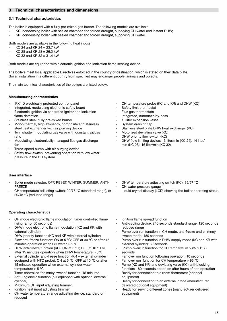
The boiler is equipped with a fully pre-mixed gas burner. The following models are available:- KC: condensing boiler with sealed chamber and forced draught, supplying CH water and instant DHW;- KR: condensing boiler with sealed chamber and forced draught, supplying CH water.
Both models are available in the following heat inputs:- KC �4 and KR �4 = �3.7 kW- KC �8 and KR �8 = �6.� kW- KC 3� and KR 3� = 31.4 kW
Both models are equipped with electronic ignition and ionization flame sensing device.
The boilers meet local applicable Directives enforced in the country of destination, which is stated on their data plate.Boiler installation in a different country from specified may endanger people, animals and objects.
The main technical characteristics of the boilers are listed below:
Manufacturing characteristics
User interface
Operating characteristics
- IPX4 D electrically protected control panel- Integrated, modulating electronic safety board- Electronic ignition via separated igniter and ionization flame detection- Stainless steel, fully pre-mixed burner- Mono-thermal, high efficiency, composite and stainless steel heat exchanger with air purging device- Twin shutter, modulating gas valve with constant air/gas ratio- Modulating, electronically managed flue gas discharge fan- Three-speed pump with air purging device- Safety flow-switch, preventing operation with low water pressure in the CH system
- CH temperature probe (KC and KR) and DHW (KC)- Safety limit thermostat- Flue gas thermostats- Integrated, automatic by-pass- 10 liter expansion vessel- System draining tap- Stainless steel plate DHW heat exchanger (KC)- Motorized deviating valve (KC)- DHW priority flow switch (KC)- DHW flow limiting device: 13 liter/min (KC �4), 14 liter/ min (KC �8), 16 liter/min (KC 3�)
- Boiler mode selector: OFF, RESET, WINTER, SUMMER, ANTI- FREEZE- CH temperature adjusting switch: �0/78 °C (standard range), or �0/45 °C (reduced range)
- DHW temperature adjusting switch (KC): 35/57 °C- CH water pressure gauge- Liquid crystal display (LCD) showing the boiler operating status
- CH mode electronic flame modulation, timer controlled flame rising ramp (50 seconds)- DHW mode electronic flame modulation (KC and KR with external cylinder)- DHW priority function (KC and KR with external cylinder)- Flow anti-freeze function: ON at 5 °C; OFF at 30 °C or after 15 minutes operation when CH water > 5 °C- DHW anti-freeze function (KC): ON at 5 °C; OFF at 10 °C or after 15 minutes operation when DHW temperature > 5°C- External cylinder anti-freeze function (KR + external cylinder equipped with NTC probe): ON at 5 °C; OFF at 10 °C or after 15 minutes operation when external cylinder water temperature > 5 °C- Timer controlled “chimney sweep” function: 15 minutes- Anti-Legionella function (KR equipped with optional external cylinder)- Maximum CH input adjusting trimmer- Ignition heat input adjusting trimmer- CH water temperature range adjusting device: standard or reduced
- Ignition flame spread function- Anti-cycling device: �40 seconds standard range, 1�0 seconds reduced range- Pump over run function in CH mode, anti-freeze and chimney sweep mode: 180 seconds- Pump over run function in DHW supply mode (KC and KR with external cylinder): 30 seconds- Pump overrun function for CH temperature > 85 °C: 30 seconds- Fan over run function following operation: 10 seconds- Fan over run function for CH temperature > 95 °C- Pump (KC and KR) and deviating valve (KC) anti-blocking function: 180 seconds operation after hours of non operation- Ready for connection to a room thermostat (optional equipment)- Ready for connection to an external probe (manufacturer delivered optional equipment)- Ready for serving different zones (manufacturer delivered equipment)
16
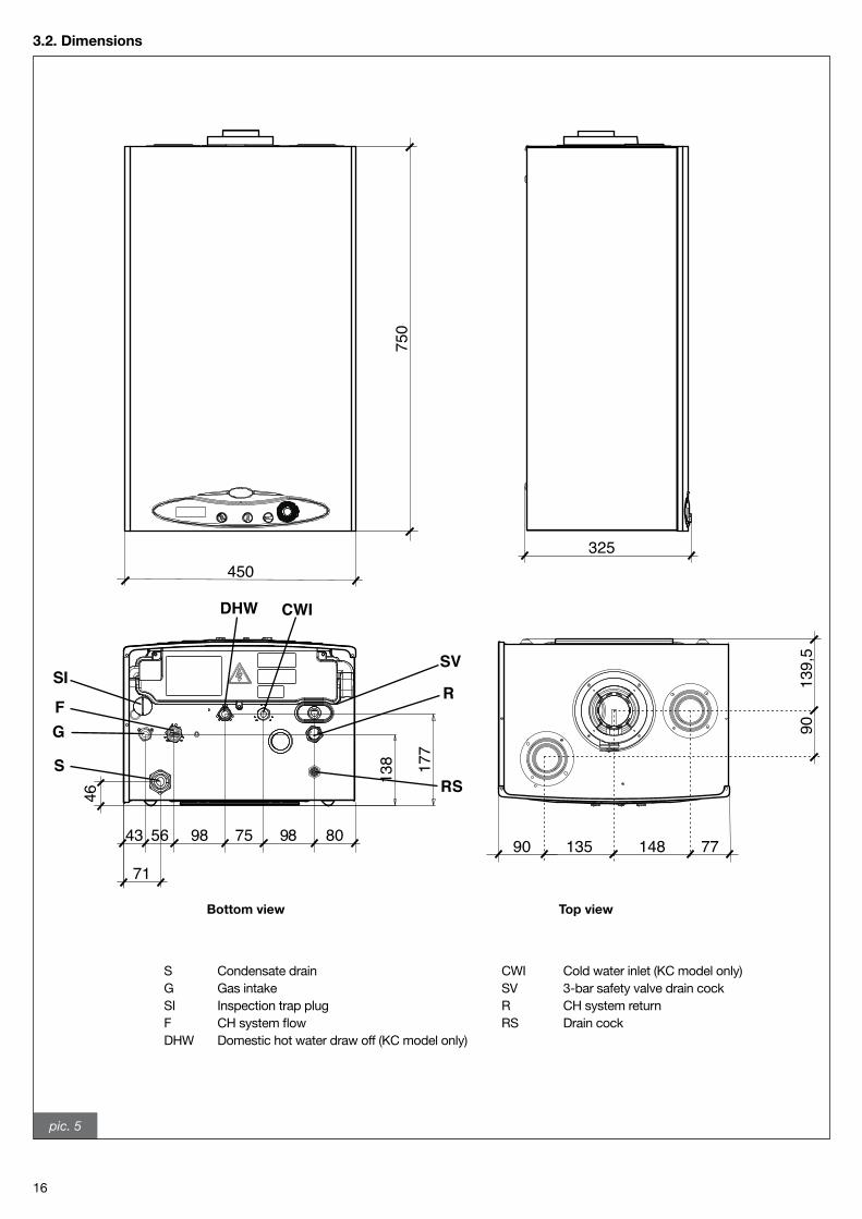
3.2. Dimensions
pic. 5
S Condensate drain G Gas intake SI Inspection trap plug F CH system flow DHW Domestic hot water draw off (KC model only)
CWI Cold water inlet (KC model only)SV 3-bar safety valve drain cock R CH system returnRS Drain cock
Bottom view Top view
139,
5
135 148
90
90 77
325
750
450
138 17
7
56 98 75 98 80
71
43
46
GF
CWI
R
S
DHW
SISV
RS
17
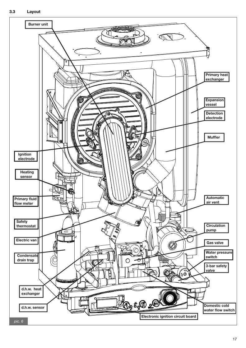
3.3 Layout
Primary heat exchanger
Expansion vessel
Detection electrode
Muffler
Automatic air vent
Circulation pump
Gas valve
3-bar safety valve
Electronic ignition circuit board
Water pressure switch
Domestic cold water flow switch
d.h.w. sensor
d.h.w. heat exchanger
Condensate drain trap
Electric van
Safety thermostat
Heating sensor
Ignition electrode
Burner unit
Primary fluid flow meter
pic. 6
18
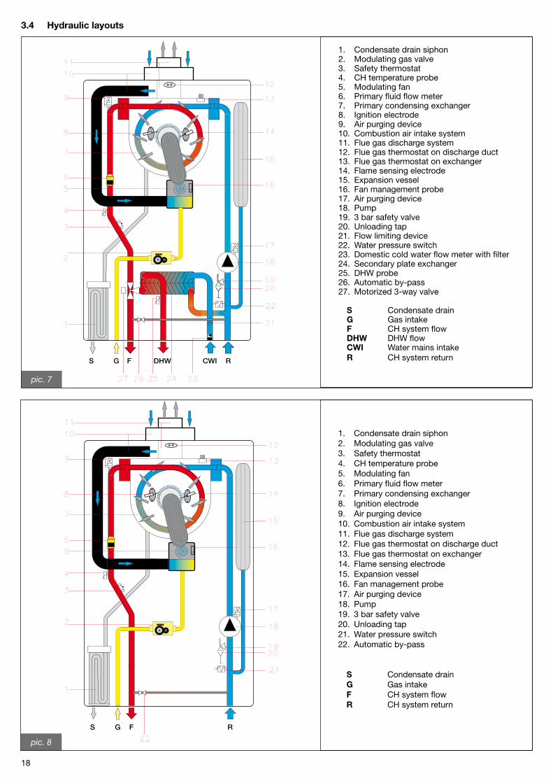
3.4 Hydraulic layouts
pic. 7
DHW CWI RFGS
1. Condensate drain siphon �. Modulating gas valve 3. Safety thermostat 4. CH temperature probe 5. Modulating fan 6. Primary fluid flow meter 7. Primary condensing exchanger 8. Ignition electrode 9. Air purging device 10. Combustion air intake system 11. Flue gas discharge system 1�. Flue gas thermostat on discharge duct 13. Flue gas thermostat on exchanger 14. Flame sensing electrode 15. Expansion vessel 16. Fan management probe 17. Air purging device 18. Pump 19. 3 bar safety valve �0. Unloading tap �1. Flow limiting device ��. Water pressure switch �3. Domestic cold water flow meter with filter �4. Secondary plate exchanger �5. DHW probe �6. Automatic by-pass �7. Motorized 3-way valve
S Condensate drain G Gas intake F CH system flow DHW DHW flow CWI Water mains intake R CH system return
1. Condensate drain siphon �. Modulating gas valve 3. Safety thermostat 4. CH temperature probe 5. Modulating fan 6. Primary fluid flow meter 7. Primary condensing exchanger 8. Ignition electrode 9. Air purging device 10. Combustion air intake system 11. Flue gas discharge system 1�. Flue gas thermostat on discharge duct 13. Flue gas thermostat on exchanger 14. Flame sensing electrode 15. Expansion vessel 16. Fan management probe 17. Air purging device 18. Pump 19. 3 bar safety valve �0. Unloading tap �1. Water pressure switch ��. Automatic by-pass
S Condensate drain G Gas intake F CH system flow R CH system return
pic. 8
FS G R
19
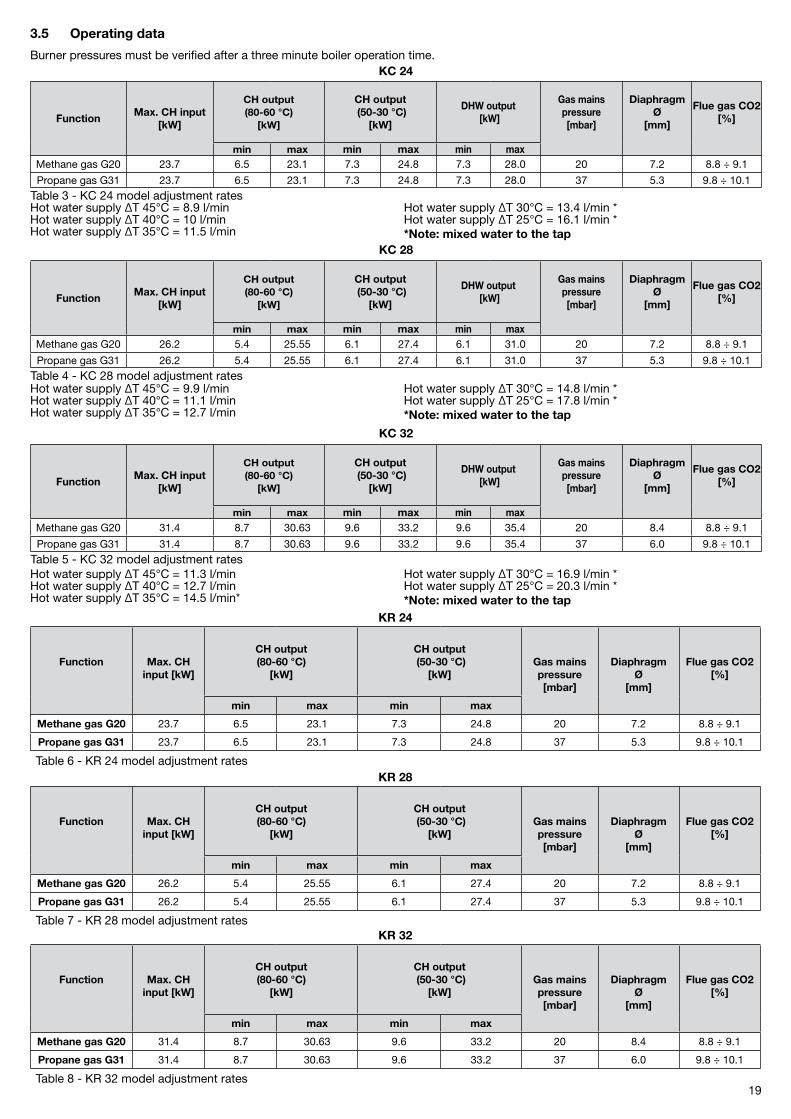
3.5 Operating data
Burner pressures must be verified after a three minute boiler operation time.KC 24
FunctionMax. CH input
[kW]
CH output(80-60 °C)
[kW]
CH output (50-30 °C)
[kW]
DHW output [kW]
Gas mainspressure [mbar]
DiaphragmØ
[mm]
Flue gas CO2[%]
min max min max min maxMethane gas G�0 �3.7 6.5 �3.1 7.3 �4.8 7.3 �8.0 �0 7.� 8.8 ÷ 9.1
Propane gas G31 �3.7 6.5 �3.1 7.3 �4.8 7.3 �8.0 37 5.3 9.8 ÷ 10.1
Table 3 - KC �4 model adjustment ratesHot water supply ΔT 45°C = 8.9 l/minHot water supply ΔT 40°C = 10 l/minHot water supply ΔT 35°C = 11.5 l/min
Hot water supply ΔT 30°C = 13.4 l/min *Hot water supply ΔT �5°C = 16.1 l/min **Note: mixed water to the tap
KC 28
FunctionMax. CH input
[kW]
CH output(80-60 °C)
[kW]
CH output (50-30 °C)
[kW]
DHW output [kW]
Gas mainspressure [mbar]
DiaphragmØ
[mm]
Flue gas CO2[%]
min max min max min maxMethane gas G�0 �6.� 5.4 �5.55 6.1 �7.4 6.1 31.0 �0 7.� 8.8 ÷ 9.1
Propane gas G31 �6.� 5.4 �5.55 6.1 �7.4 6.1 31.0 37 5.3 9.8 ÷ 10.1
Table 4 - KC �8 model adjustment ratesHot water supply ΔT 45°C = 9.9 l/minHot water supply ΔT 40°C = 11.1 l/minHot water supply ΔT 35°C = 1�.7 l/min
Hot water supply ΔT 30°C = 14.8 l/min *Hot water supply ΔT �5°C = 17.8 l/min **Note: mixed water to the tap
KC 32
FunctionMax. CH input
[kW]
CH output(80-60 °C)
[kW]
CH output (50-30 °C)
[kW]
DHW output [kW]
Gas mainspressure [mbar]
DiaphragmØ
[mm]
Flue gas CO2[%]
min max min max min maxMethane gas G�0 31.4 8.7 30.63 9.6 33.� 9.6 35.4 �0 8.4 8.8 ÷ 9.1
Propane gas G31 31.4 8.7 30.63 9.6 33.� 9.6 35.4 37 6.0 9.8 ÷ 10.1
Table 5 - KC 3� model adjustment ratesHot water supply ΔT 45°C = 11.3 l/minHot water supply ΔT 40°C = 1�.7 l/minHot water supply ΔT 35°C = 14.5 l/min*
Hot water supply ΔT 30°C = 16.9 l/min *Hot water supply ΔT �5°C = �0.3 l/min **Note: mixed water to the tap
KR 24
Function Max. CH input [kW]
CH output(80-60 °C)
[kW]
CH output (50-30 °C)
[kW]Gas mainspressure [mbar]
DiaphragmØ
[mm]
Flue gas CO2[%]
min max min max
Methane gas G20 �3.7 6.5 �3.1 7.3 �4.8 �0 7.� 8.8 ÷ 9.1
Propane gas G31 �3.7 6.5 �3.1 7.3 �4.8 37 5.3 9.8 ÷ 10.1
Table 6 - KR �4 model adjustment ratesKR 28
Function Max. CH input [kW]
CH output(80-60 °C)
[kW]
CH output (50-30 °C)
[kW]Gas mainspressure [mbar]
DiaphragmØ
[mm]
Flue gas CO2[%]
min max min max
Methane gas G20 �6.� 5.4 �5.55 6.1 �7.4 �0 7.� 8.8 ÷ 9.1
Propane gas G31 �6.� 5.4 �5.55 6.1 �7.4 37 5.3 9.8 ÷ 10.1
Table 7 - KR �8 model adjustment ratesKR 32
Function Max. CH input [kW]
CH output(80-60 °C)
[kW]
CH output (50-30 °C)
[kW]Gas mainspressure [mbar]
DiaphragmØ
[mm]
Flue gas CO2[%]
min max min max
Methane gas G20 31.4 8.7 30.63 9.6 33.� �0 8.4 8.8 ÷ 9.1
Propane gas G31 31.4 8.7 30.63 9.6 33.� 37 6.0 9.8 ÷ 10.1
Table 8 - KR 3� model adjustment rates
�0
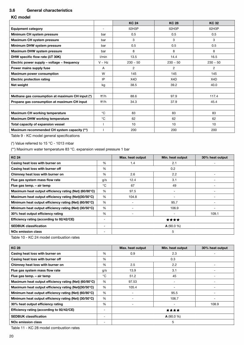
3.6 General characteristics
KC modelKC 24 KC 28 KC 32
Equipment category - II�H3P II�H3P II�H3P
Minimum CH system pressure bar 0.5 0.5 0.5
Maximum CH system pressure bar 3 3 3
Minimum DHW system pressure bar 0.5 0.5 0.5
Maximum DHW system pressure bar 8 8 8
DHW specific flow rate (ΔT 30K) l/min 13.5 14.4 16.5
Electric power supply – voltage ~ frequency V ~ Hz �30 ~ 50 �30 ~ 50 �30 ~ 50
Power mains supply fuse A � � �
Maximum power consumption W 145 145 145
Electric protection rating IP X4D X4D X4D
Net weight kg 38.5 39.� 40.0
Methane gas consumption at maximum CH input (*) ft3/h 88.6 97.9 117.4
Propane gas consumption at maximum CH input ft3/h 34.3 37.9 45.4
Maximum CH working temperature °C 83 83 83
Maximum DHW working temperature °C 6� 6� 6�
Total capacity of expansion vessel l 10 10 10
Maximum recommended CH system capacity (**) l �00 �00 �00
Table 9 - KC model general specifications
(*) Value referred to 15 °C - 1013 mbar
(**) Maximum water temperature 83 °C. expansion vessel pressure 1 bar
KC 24 Max. heat output Min. heat output 30% heat output
Casing heat loss with burner on % 1.4 �.1 -
Casing heat loss with burner off % 0.�
Chimney heat loss with burner on % �.6 �.� -
Flue gas system mass flow rate g/s 1�.4 3.1 -
Flue gas temp. – air temp °C 67 49 -
Maximum heat output efficiency rating (Net) (60/80°C) % 97.5 - -
Maximum heat output efficiency rating (Net)(30/50°C) % 104.8 - -
Minimum heat output efficiency rating (Net) (60/80°C) % - 95.7 -
Minimum heat output efficiency rating (Net) (30/50°C) % - 106.9 -
30% heat output efficiency rating % - - 109.1
Efficiency rating (according to 92/42/CE) -
SEDBUK classification - A (90.0 %)
NOx emission class - 5
Table 10 - KC �4 model combustion rates
KC 28 Max. heat output Min. heat output 30% heat output
Casing heat loss with burner on % 0.9 �.3 -
Casing heat loss with burner off % 0.3
Chimney heat loss with burner on % �.5 �.� -
Flue gas system mass flow rate g/s 13.9 3.1 -
Flue gas temp. – air temp °C 51.� 45 -
Maximum heat output efficiency rating (Net) (60/80°C) % 97.53 - -
Maximum heat output efficiency rating (Net)(30/50°C) % 105.4 - -
Minimum heat output efficiency rating (Net) (60/80°C) % - 95.5 -
Minimum heat output efficiency rating (Net) (30/50°C) % - 106.7 -
30% heat output efficiency rating % - - 108.9
Efficiency rating (according to 92/42/CE) -
SEDBUK classification - A (90.0 %)
NOx emission class - 5
Table 11 - KC �8 model combustion rates

�1
KC 32 Max. heat output Min. heat output 30% heat output
Casing heat loss with burner on % 0.6 1.6 -
Casing heat loss with burner off % 0.�
Chimney heat loss with burner on % �.4 �.1 -
Flue gas system mass flow rate g/s 15.7 4.1 -
Flue gas temp. – air temp °C 54 51 -
Maximum heat output efficiency rating (Net) (60/80°C) % 97.57 - -
Maximum heat output efficiency rating (Net)(30/50°C) % 105.4 - -
Minimum heat output efficiency rating (Net) (60/80°C) % - 96.3 -
Minimum heat output efficiency rating (Net) (30/50°C) % - 106.3 -
30% heat output efficiency rating % - - 108.7
Efficiency rating (according to 92/42/CE) -
SEDBUK classification - A (90.1 %)
NOx emission class - 5
Table 1� - KC 3� model combustion rates
KR modelKR 24 KR 28 KR 32
Equipment category - II�H3P II�H3P II�H3P
Minimum CH system pressure bar 0.5 0.5 0.5
Maximum CH system pressure bar 3 3 3
Electric power supply – voltage ~ frequency V ~ Hz �30 ~ 50 �30 ~ 50 �30 ~ 50
Power mains supply fuse A � � �
Maximum power consumption W 145 145 145
Electric protection rating IP X4D X4D X4D
Net weight kg 37.5 38.� 39.0
Methane gas consumption at maximum CH input (*) ft3/h 88.6 97.9 117.4
Propane gas consumption at maximum CH input ft3/h 34.3 37.9 45.4
Maximum CH working temperature °C 83 83 83
Total capacity of expansion vessel l 10 10 10
Maximum recommended CH system capacity (**) l �00 �00 �00
Table 13 - KR model general specifications
(*) Value referred to 15 °C - 1013 mbar
(**) Maximum water temperature 83 °C. expansion vessel pressure 1 bar
KR 24 Max. heat output Min. heat output 30% heat output
Casing heat loss with burner on % 1.4 �.1 -
Casing heat loss with burner off % 0.�
Chimney heat loss with burner on % �.6 �.� -
Flue gas system mass flow rate g/s 1�.4 3.1 -
Flue gas temp. – air temp °C 67 49 -
Maximum heat output efficiency rating (Net) (60/80°C) % 97.5 - -
Maximum heat output efficiency rating (Net)(30/50°C) % 104.8 - -
Minimum heat output efficiency rating (Net) (60/80°C) % - 95.7 -
Minimum heat output efficiency rating (Net) (30/50°C) % - 106.9 -
30% heat output efficiency rating % - - 109.1
Efficiency rating (according to 92/42/CE) -
SEDBUK classification - A (90.1 %)
NOx emission class - 5
Table 14 - KR �4 model combustion rates
��
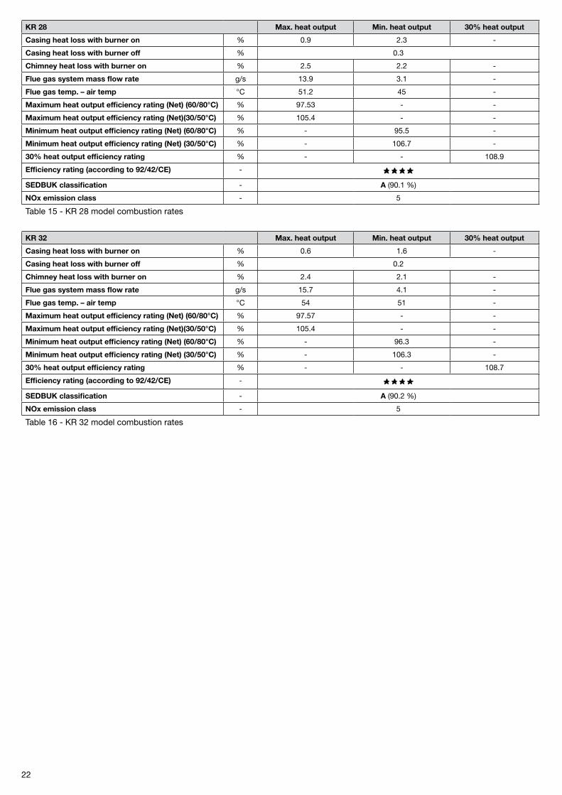
KR 28 Max. heat output Min. heat output 30% heat output
Casing heat loss with burner on % 0.9 �.3 -
Casing heat loss with burner off % 0.3
Chimney heat loss with burner on % �.5 �.� -
Flue gas system mass flow rate g/s 13.9 3.1 -
Flue gas temp. – air temp °C 51.� 45 -
Maximum heat output efficiency rating (Net) (60/80°C) % 97.53 - -
Maximum heat output efficiency rating (Net)(30/50°C) % 105.4 - -
Minimum heat output efficiency rating (Net) (60/80°C) % - 95.5 -
Minimum heat output efficiency rating (Net) (30/50°C) % - 106.7 -
30% heat output efficiency rating % - - 108.9
Efficiency rating (according to 92/42/CE) -
SEDBUK classification - A (90.1 %)
NOx emission class - 5
Table 15 - KR �8 model combustion rates
KR 32 Max. heat output Min. heat output 30% heat output
Casing heat loss with burner on % 0.6 1.6 -
Casing heat loss with burner off % 0.�
Chimney heat loss with burner on % �.4 �.1 -
Flue gas system mass flow rate g/s 15.7 4.1 -
Flue gas temp. – air temp °C 54 51 -
Maximum heat output efficiency rating (Net) (60/80°C) % 97.57 - -
Maximum heat output efficiency rating (Net)(30/50°C) % 105.4 - -
Minimum heat output efficiency rating (Net) (60/80°C) % - 96.3 -
Minimum heat output efficiency rating (Net) (30/50°C) % - 106.3 -
30% heat output efficiency rating % - - 108.7
Efficiency rating (according to 92/42/CE) -
SEDBUK classification - A (90.� %)
NOx emission class - 5
Table 16 - KR 3� model combustion rates

�3
pic. 9
V1
V2
V3
V1
V2
V3
V1 Speed I (min) V2 Speed II V3 Speed III (max)
600
500
400
300
200
100
00 200 400 600 800 1000
KC/KR 24 model
Flow rate [l/h]
Head
ava
ilabl
e [m
bar]
KC/KR 28 model
Flow rate [l/h]
Head
ava
ilabl
e [m
bar]
600
500
400
300
200
100
00 200 400 600 800 1000
KC/KR 32 model
Flow rate [l/h]
Hea
d av
aila
ble
[mba
r]
V1
V2
V3
�4
4 Instructions for the fitter
This is an II�H3P category boiler and must be installed in compliance with laws and standards enforced in the country of installation, which are here considered as entirely transcribed.
4.1 Reference standard
In GB, the installation must be carried out by a CORGI Registered Installer. To check for authorised qualified engineers please contact CORGI 01�56-37�400. It must be carried out in accordance with the relevant requirements of the:
- Gas Safety Regulations;
- The appropriate Building Regulations either The Building Regulation, The Building Regulations (Scotland), Building Regulations (Northern Ireland);
- The Water Fittings Regulations or Water Byelaws in Scotland;
- The current I.E.E. Wiring Regulations.
Where no specific instructions are given, reference should be made to the relevant British Standards Code of Practice.The following list is the full lists of codes of practice and British Standards that engineers should work to in the UK.
It is law in the UK that a competent person installs all gas-burning appliances. Please ensure that the installer is a class of person ap-proved for the time being by the Heath and Safety Executive for the purpose of carrying out this work. An approved engineer should be registered to an approved scheme i.e. CORGI 01�56-37�400.
In GB, the following Codes of Practice apply:
BS 5440: Part 1 �000 - Flues
BS 5440: Part � �000 - Air Supply
BS 5446: Installation of hot water supplies for domestic purposes (1st, �nd and 3rd family gases)
BS 5449: 1990 Forced circulation hot water systems
BS 6700: 1987 - Installation of cold water supplies for domestic purposes (1st, �nd and 3rd family gases)
BS 6798: �000 Specification for installation of gas-fired boilers of rated input not exceeding 70 kW net
BS 6891: Specification for installation of low pressure gas pipe work of up to �8 mm (R!) in domestic premises (�nd family gas)
BS 7074: Expansion Vessels and ancillary equipment for sealed water systems
BS 7593: 199� Code of practice for treatment of water in domestic hot water central heating systems
BS 7671: �001 IEE wiring regulations.
This appliance meets the requirements of:- UNI EN 677 for GAS-FIRED CENTRAL HEATING BOILERS. SPECIFIC REQUIREMENTS FOR CONDENSING BOILERS WITH NOMINAL HEAT INPUT ≤ 70 kW,
- IPX4D rating for electrical appliances,
- EMC DIRECTIVE 89/336 CE,
- LVD DIRECTIVE �006/95 CE,
- BOILER EFFICIENCY DIRECTIVE 9�/4� CE
Failure to install a gas appliance correctly and in accordance with the above norms could lead to prosecution. It is in the interest of the installer and safety that the law is complied with.
The manufacturers instructions form an integral part of the installation and should be left with the appliance but do not over ride in any-way statutory obligations.
�5
4.2 System details
4.2.1 Central heating circuit
The boiler is designed for use in a sealed central heating system in accordance with the requirements of BS 5449 and BS 6798. The system should be designed to operate with flow temperatures of up to 78 °C. When designing the system, the pump head, expansion vessel size, mean radiator temperature, ect. must all be taken into account. Refer to the pump performance table for guidelines.System volume: the expansion vessel incorporated into the boiler is suitable for a sealed heating system. The boiler is supplied with the following components built in:
Pressure relief valve: set to operate at 3 bars. The outlet connection of the boiler safety valve must terminate to atmosphere in accord-ance with current regulations. The manufacturer will not be held responsible for flooding caused by the operation of the safety valve in the case of system overpressure.
Pressure gauge: to indicates the system pressure to be maintained.
Expansion vessel: capacity of 10 litres.
By-pass: the boiler incorporates an automatic by-pass.
All recirculatory water systems will be subject to corrosion unless an appropriate water treatment is applied. This means that the efficien-cy of the system will deteriorate as corrosion sludge accumulates within the system, risking damage to pump and valves, boiler noise and circulation problems.All systems must be thoroughly drained and flushed out. System additives - corrosion inhibitors and flushing agents/descalers should comply to BS7593 requirements. It is important to check the inhibitor concentration after installation, system modification and at every service in accordance with the manufacturer’s instructions.
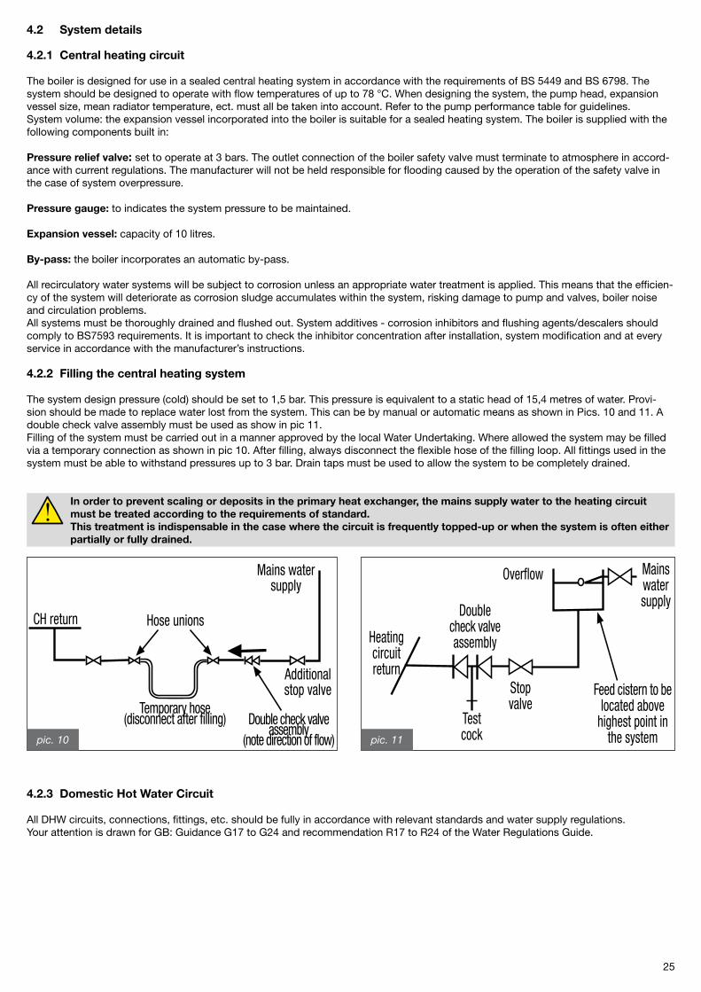
4.2.2 Filling the central heating system
The system design pressure (cold) should be set to 1,5 bar. This pressure is equivalent to a static head of 15,4 metres of water. Provi-sion should be made to replace water lost from the system. This can be by manual or automatic means as shown in Pics. 10 and 11. A double check valve assembly must be used as show in pic 11.Filling of the system must be carried out in a manner approved by the local Water Undertaking. Where allowed the system may be filled via a temporary connection as shown in pic 10. After filling, always disconnect the flexible hose of the filling loop. All fittings used in the system must be able to withstand pressures up to 3 bar. Drain taps must be used to allow the system to be completely drained.
In order to prevent scaling or deposits in the primary heat exchanger, the mains supply water to the heating circuit must be treated according to the requirements of standard. This treatment is indispensable in the case where the circuit is frequently topped-up or when the system is often either partially or fully drained.
4.2.3 Domestic Hot Water Circuit
All DHW circuits, connections, fittings, etc. should be fully in accordance with relevant standards and water supply regulations.Your attention is drawn for GB: Guidance G17 to G�4 and recommendation R17 to R�4 of the Water Regulations Guide.
Mains watersupply
Additionalstop valve
Hose unionsCH return
Temporary hose(disconnect after filling) Double check valve
assembly(note direction of flow)
Mainswatersupply
Overflow
Stopvalve
Testcock
Doublecheck valveassemblyHeating
circuitreturn
Feed cistern to belocated above
highest point inthe systempic. 10 pic. 11
�6
4.3 Site requirements
4.3.1 Choosing where to install the boiler
The following must be taken into account when choosing where to install the boiler:
- Approved document L1 + L� government guidelines;
- 4.5.1 Air intake /flue gas discharge system paragraph instructions;
- check the wall for sturdiness, avoiding weak areas;
- do not hang the boiler above any equipment which may prejudice proper operation (steam and greasy vapor emitting kitchen appliances, washing machines, etc.).
pic. 12
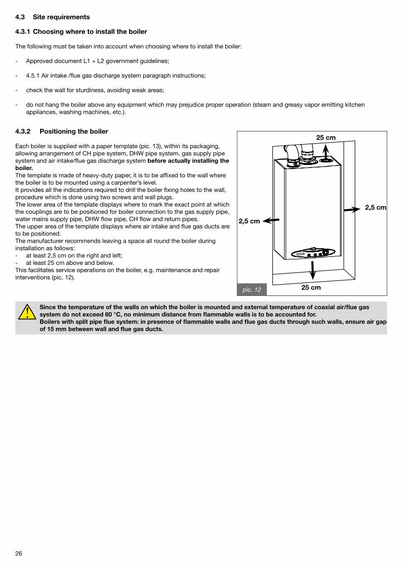
2,5 cm
2,5 cm
25 cm
25 cm4.3.2 Positioning the boiler
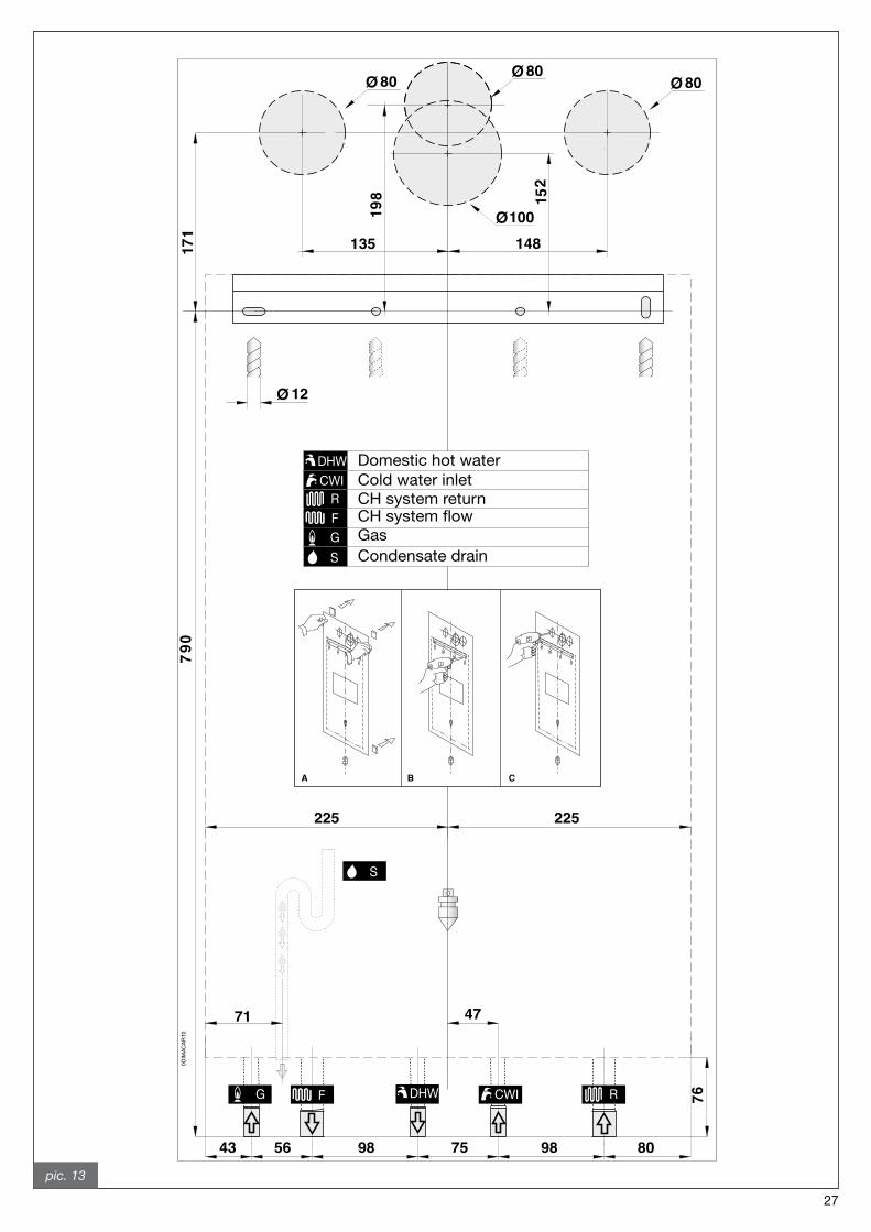
Each boiler is supplied with a paper template (pic. 13), within its packaging, allowing arrangement of CH pipe system, DHW pipe system, gas supply pipe system and air intake/flue gas discharge system before actually installing the boiler.The template is made of heavy-duty paper, it is to be affixed to the wall where the boiler is to be mounted using a carpenter’s level.It provides all the indications required to drill the boiler fixing holes to the wall, procedure which is done using two screws and wall plugs.The lower area of the template displays where to mark the exact point at which the couplings are to be positioned for boiler connection to the gas supply pipe, water mains supply pipe, DHW flow pipe, CH flow and return pipes.The upper area of the template displays where air intake and flue gas ducts are to be positioned.The manufacturer recommends leaving a space all round the boiler during installation as follows: - at least �,5 cm on the right and left;- at least �5 cm above and below.This facilitates service operations on the boiler, e.g. maintenance and repair interventions (pic. 1�).
Since the temperature of the walls on which the boiler is mounted and external temperature of coaxial air/flue gas system do not exceed 60 °C, no minimum distance from flammable walls is to be accounted for. Boilers with split pipe flue system: in presence of flammable walls and flue gas ducts through such walls, ensure air gap of 15 mm between wall and flue gas ducts.
�7
G F DHW CWI R
S
Domestic hot water Cold water inlet CH system return
Gas Condensate drain
DHWCWI
R
FG
S
G F DHW CWI R
S
pic. 13
�8
4.3.3. Boiler room ventilation
The boiler has sealed combustion chamber. Combustion air is not drawn from boiler room therefore specific recommendations need not to be applied concerning the boiler room or openings and ventilation provided to the boiler room.
It is mandatory to install the boiler in an adequate room following laws and standards applicable in the country of installation, which are considered as fully transcribed in this manual.
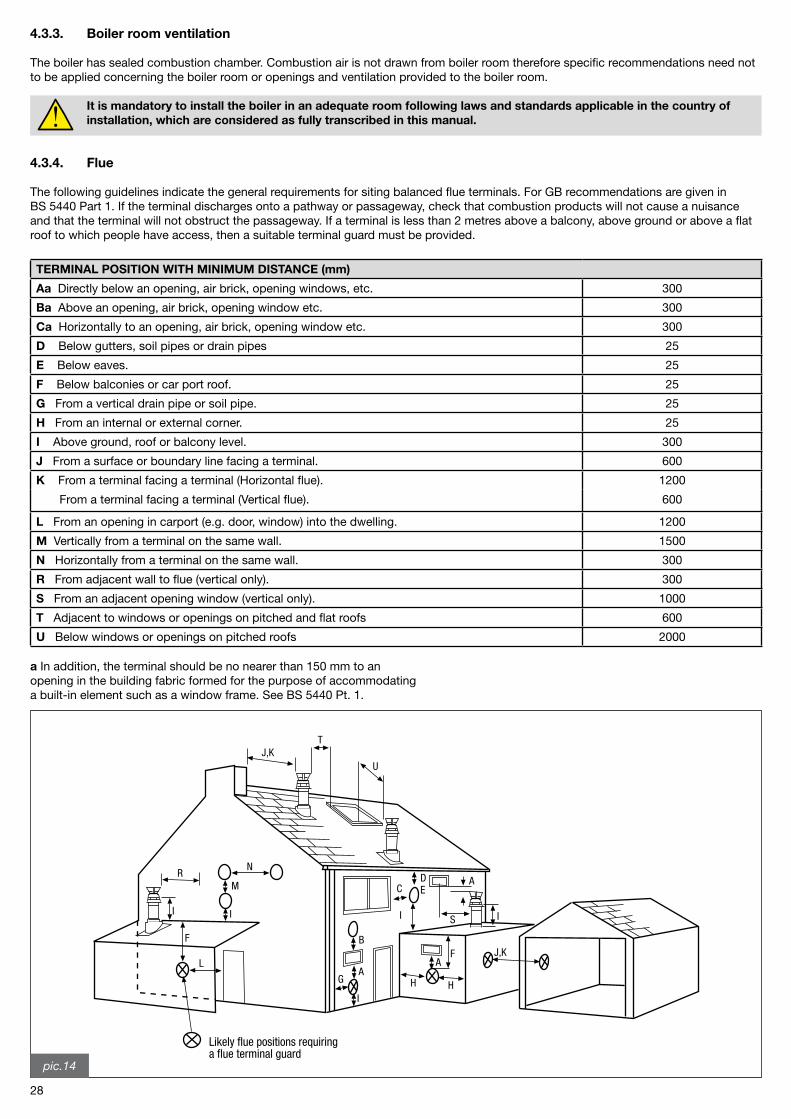
4.3.4. Flue
The following guidelines indicate the general requirements for siting balanced flue terminals. For GB recommendations are given in BS 5440 Part 1. If the terminal discharges onto a pathway or passageway, check that combustion products will not cause a nuisanceand that the terminal will not obstruct the passageway. If a terminal is less than � metres above a balcony, above ground or above a flat roof to which people have access, then a suitable terminal guard must be provided.
TERMINAL POSITION WITH MINIMUM DISTANCE (mm)
Aa Directly below an opening, air brick, opening windows, etc. 300
Ba Above an opening, air brick, opening window etc. 300
Ca Horizontally to an opening, air brick, opening window etc. 300
D Below gutters, soil pipes or drain pipes �5
E Below eaves. �5
F Below balconies or car port roof. �5
G From a vertical drain pipe or soil pipe. �5
H From an internal or external corner. �5
I Above ground, roof or balcony level. 300
J From a surface or boundary line facing a terminal. 600
K From a terminal facing a terminal (Horizontal flue). 1�00
From a terminal facing a terminal (Vertical flue). 600
L From an opening in carport (e.g. door, window) into the dwelling. 1�00
M Vertically from a terminal on the same wall. 1500
N Horizontally from a terminal on the same wall. 300
R From adjacent wall to flue (vertical only). 300
S From an adjacent opening window (vertical only). 1000
T Adjacent to windows or openings on pitched and flat roofs 600
U Below windows or openings on pitched roofs �000
a In addition, the terminal should be no nearer than 150 mm to anopening in the building fabric formed for the purpose of accommodatinga built-in element such as a window frame. See BS 5440 Pt. 1.
HH
AF J,K
S I
AE
I
CD
I
AG
B
U
TJ,K
N
M
I
R
I
F
L
Likely flue positions requiringa flue terminal guard
pic.14
�9
4.4 Installation (authorised personnel)
Accessories and spare parts for installation and service procedures are to be supplied by the Manufacturer. Should non original accessories and spare parts be employed, boiler proper performance is not guaranteed.
4.4.1 Packaging
Boiler is shipped in a sturdy cardboard box. Remove boiler from cardboard box and check its integrity.The packing materials can be recycled. Disposal of must be managed via appropriate waste collection sites.Keep packaging out of reach of children, as it may be dangerous.Manufacturer shall not be held responsible for harm to people and/or animals, and/or damage to property due to failure in following the above mentioned instructions
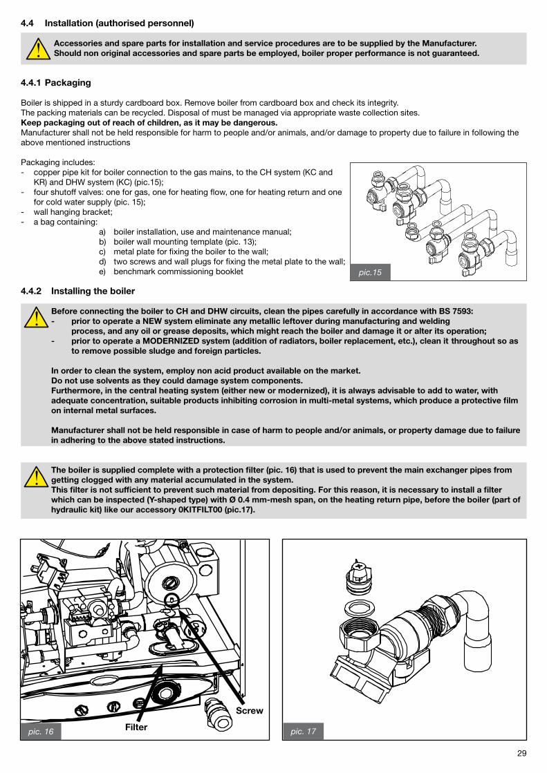
Packaging includes:- copper pipe kit for boiler connection to the gas mains, to the CH system (KC and KR) and DHW system (KC) (pic.15);- four shutoff valves: one for gas, one for heating flow, one for heating return and one for cold water supply (pic. 15);- wall hanging bracket;- a bag containing: a) boiler installation, use and maintenance manual; b) boiler wall mounting template (pic. 13); c) metal plate for fixing the boiler to the wall; d) two screws and wall plugs for fixing the metal plate to the wall; e) benchmark commissioning booklet
4.4.2 Installing the boiler
Before connecting the boiler to CH and DHW circuits, clean the pipes carefully in accordance with BS 7593: - prior to operate a NEW system eliminate any metallic leftover during manufacturing and welding process, and any oil or grease deposits, which might reach the boiler and damage it or alter its operation; - prior to operate a MODERNIZED system (addition of radiators, boiler replacement, etc.), clean it throughout so as to remove possible sludge and foreign particles.
In order to clean the system, employ non acid product available on the market. Do not use solvents as they could damage system components. Furthermore, in the central heating system (either new or modernized), it is always advisable to add to water, with adequate concentration, suitable products inhibiting corrosion in multi-metal systems, which produce a protective film on internal metal surfaces.
Manufacturer shall not be held responsible in case of harm to people and/or animals, or property damage due to failure in adhering to the above stated instructions.
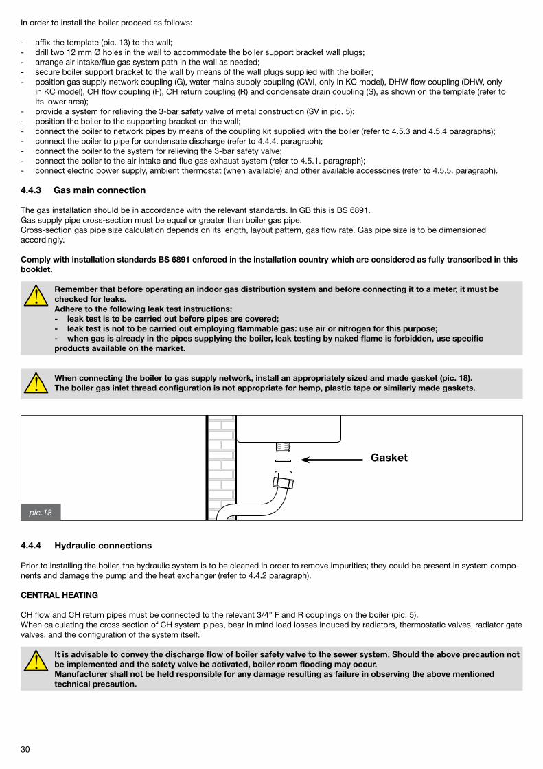
The boiler is supplied complete with a protection filter (pic. 16) that is used to prevent the main exchanger pipes from getting clogged with any material accumulated in the system. This filter is not sufficient to prevent such material from depositing. For this reason, it is necessary to install a filter which can be inspected (Y-shaped type) with Ø 0.4 mm-mesh span, on the heating return pipe, before the boiler (part of hydraulic kit) like our accessory 0KITFILT00 (pic.17).
Filter
pic.15
pic. 16
76
pic. 17
Screw
30
In order to install the boiler proceed as follows:
- affix the template (pic. 13) to the wall;- drill two 1� mm Ø holes in the wall to accommodate the boiler support bracket wall plugs;- arrange air intake/flue gas system path in the wall as needed;- secure boiler support bracket to the wall by means of the wall plugs supplied with the boiler;- position gas supply network coupling (G), water mains supply coupling (CWI, only in KC model), DHW flow coupling (DHW, only in KC model), CH flow coupling (F), CH return coupling (R) and condensate drain coupling (S), as shown on the template (refer to its lower area);- provide a system for relieving the 3-bar safety valve of metal construction (SV in pic. 5);- position the boiler to the supporting bracket on the wall;- connect the boiler to network pipes by means of the coupling kit supplied with the boiler (refer to 4.5.3 and 4.5.4 paragraphs);- connect the boiler to pipe for condensate discharge (refer to 4.4.4. paragraph);- connect the boiler to the system for relieving the 3-bar safety valve;- connect the boiler to the air intake and flue gas exhaust system (refer to 4.5.1. paragraph);- connect electric power supply, ambient thermostat (when available) and other available accessories (refer to 4.5.5. paragraph).
4.4.3 Gas main connection
The gas installation should be in accordance with the relevant standards. In GB this is BS 6891.Gas supply pipe cross-section must be equal or greater than boiler gas pipe.Cross-section gas pipe size calculation depends on its length, layout pattern, gas flow rate. Gas pipe size is to be dimensioned accordingly.
Comply with installation standards BS 6891 enforced in the installation country which are considered as fully transcribed in this booklet.
Remember that before operating an indoor gas distribution system and before connecting it to a meter, it must be checked for leaks. Adhere to the following leak test instructions: - leak test is to be carried out before pipes are covered; - leak test is not to be carried out employing flammable gas: use air or nitrogen for this purpose; - when gas is already in the pipes supplying the boiler, leak testing by naked flame is forbidden, use specific products available on the market.
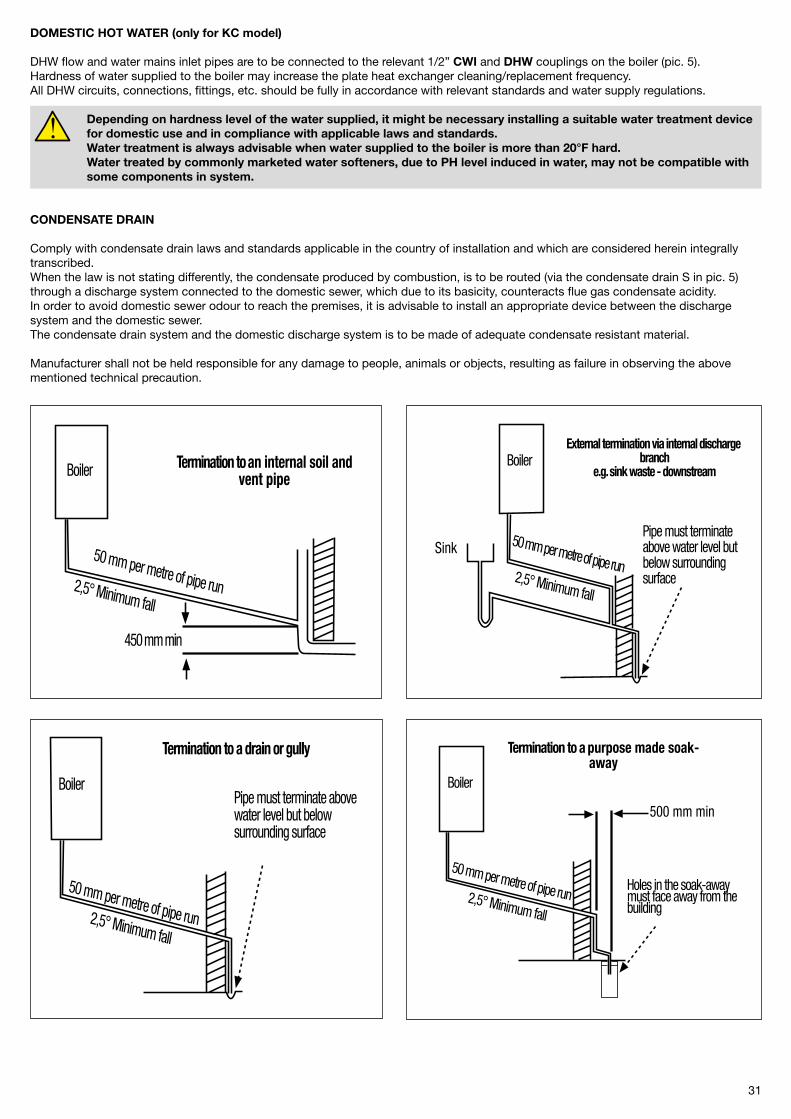
When connecting the boiler to gas supply network, install an appropriately sized and made gasket (pic. 18). The boiler gas inlet thread configuration is not appropriate for hemp, plastic tape or similarly made gaskets.
4.4.4 Hydraulic connections
Prior to installing the boiler, the hydraulic system is to be cleaned in order to remove impurities; they could be present in system compo-nents and damage the pump and the heat exchanger (refer to 4.4.� paragraph).
CENTRAL HEATING
CH flow and CH return pipes must be connected to the relevant 3/4” F and R couplings on the boiler (pic. 5).When calculating the cross section of CH system pipes, bear in mind load losses induced by radiators, thermostatic valves, radiator gate valves, and the configuration of the system itself.
It is advisable to convey the discharge flow of boiler safety valve to the sewer system. Should the above precaution not be implemented and the safety valve be activated, boiler room flooding may occur. Manufacturer shall not be held responsible for any damage resulting as failure in observing the above mentioned technical precaution.
pic.18
Gasket
31
DOMESTIC HOT WATER (only for KC model)
DHW flow and water mains inlet pipes are to be connected to the relevant 1/�” CWI and DHW couplings on the boiler (pic. 5).Hardness of water supplied to the boiler may increase the plate heat exchanger cleaning/replacement frequency.All DHW circuits, connections, fittings, etc. should be fully in accordance with relevant standards and water supply regulations.
Depending on hardness level of the water supplied, it might be necessary installing a suitable water treatment device for domestic use and in compliance with applicable laws and standards. Water treatment is always advisable when water supplied to the boiler is more than 20°F hard. Water treated by commonly marketed water softeners, due to PH level induced in water, may not be compatible with some components in system.
CONDENSATE DRAIN
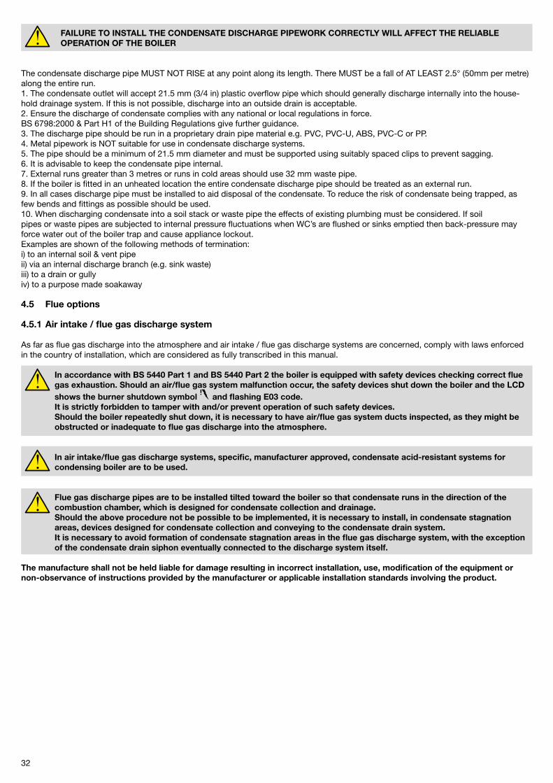
Comply with condensate drain laws and standards applicable in the country of installation and which are considered herein integrally transcribed.When the law is not stating differently, the condensate produced by combustion, is to be routed (via the condensate drain S in pic. 5) through a discharge system connected to the domestic sewer, which due to its basicity, counteracts flue gas condensate acidity.In order to avoid domestic sewer odour to reach the premises, it is advisable to install an appropriate device between the discharge system and the domestic sewer.The condensate drain system and the domestic discharge system is to be made of adequate condensate resistant material.
Manufacturer shall not be held responsible for any damage to people, animals or objects, resulting as failure in observing the above mentioned technical precaution.
50 mm per metre of pipe run2,5° Minimum fall
Boiler Termination to an internal soil andvent pipe
450 mm min
BoilerExternal termination via internal discharge
branch e.g. sink waste - downstream
Pipe must terminateabove water level butbelow surroundingsurface
50 mm per metre of pipe run2,5° Minimum fall
Sink
BoilerPipe must terminate abovewater level but belowsurrounding surface
Termination to a drain or gully
50 mm per metre of pipe run2,5° Minimum fall
Boiler
50 mm per metre of pipe run2,5° Minimum fall
Termination to a purpose made soak-away
Holes in the soak-awaymust face away from thebuilding
500 mm min
3�
FAILURE TO INSTALL THE CONDENSATE DISCHARGE PIPEWORK CORRECTLY WILL AFFECT THE RELIABLE OPERATION OF THE BOILER
The condensate discharge pipe MUST NOT RISE at any point along its length. There MUST be a fall of AT LEAST �.5° (50mm per metre) along the entire run.1. The condensate outlet will accept �1.5 mm (3/4 in) plastic overflow pipe which should generally discharge internally into the house-hold drainage system. If this is not possible, discharge into an outside drain is acceptable.�. Ensure the discharge of condensate complies with any national or local regulations in force.BS 6798:�000 & Part H1 of the Building Regulations give further guidance.3. The discharge pipe should be run in a proprietary drain pipe material e.g. PVC, PVC-U, ABS, PVC-C or PP.4. Metal pipework is NOT suitable for use in condensate discharge systems.5. The pipe should be a minimum of �1.5 mm diameter and must be supported using suitably spaced clips to prevent sagging.6. It is advisable to keep the condensate pipe internal.7. External runs greater than 3 metres or runs in cold areas should use 3� mm waste pipe.8. If the boiler is fitted in an unheated location the entire condensate discharge pipe should be treated as an external run.9. In all cases discharge pipe must be installed to aid disposal of the condensate. To reduce the risk of condensate being trapped, as few bends and fittings as possible should be used.10. When discharging condensate into a soil stack or waste pipe the effects of existing plumbing must be considered. If soilpipes or waste pipes are subjected to internal pressure fluctuations when WC’s are flushed or sinks emptied then back-pressure may force water out of the boiler trap and cause appliance lockout.Examples are shown of the following methods of termination:i) to an internal soil & vent pipeii) via an internal discharge branch (e.g. sink waste)iii) to a drain or gullyiv) to a purpose made soakaway
4.5 Flue options
4.5.1 Air intake / flue gas discharge system
As far as flue gas discharge into the atmosphere and air intake / flue gas discharge systems are concerned, comply with laws enforced in the country of installation, which are considered as fully transcribed in this manual.
In accordance with BS 5440 Part 1 and BS 5440 Part 2 the boiler is equipped with safety devices checking correct flue gas exhaustion. Should an air/flue gas system malfunction occur, the safety devices shut down the boiler and the LCD shows the burner shutdown symbol and flashing E03 code. It is strictly forbidden to tamper with and/or prevent operation of such safety devices. Should the boiler repeatedly shut down, it is necessary to have air/flue gas system ducts inspected, as they might be obstructed or inadequate to flue gas discharge into the atmosphere.
In air intake/flue gas discharge systems, specific, manufacturer approved, condensate acid-resistant systems for condensing boiler are to be used.
Flue gas discharge pipes are to be installed tilted toward the boiler so that condensate runs in the direction of the combustion chamber, which is designed for condensate collection and drainage. Should the above procedure not be possible to be implemented, it is necessary to install, in condensate stagnation areas, devices designed for condensate collection and conveying to the condensate drain system. It is necessary to avoid formation of condensate stagnation areas in the flue gas discharge system, with the exception of the condensate drain siphon eventually connected to the discharge system itself.
The manufacture shall not be held liable for damage resulting in incorrect installation, use, modification of the equipment or non-observance of instructions provided by the manufacturer or applicable installation standards involving the product.
33
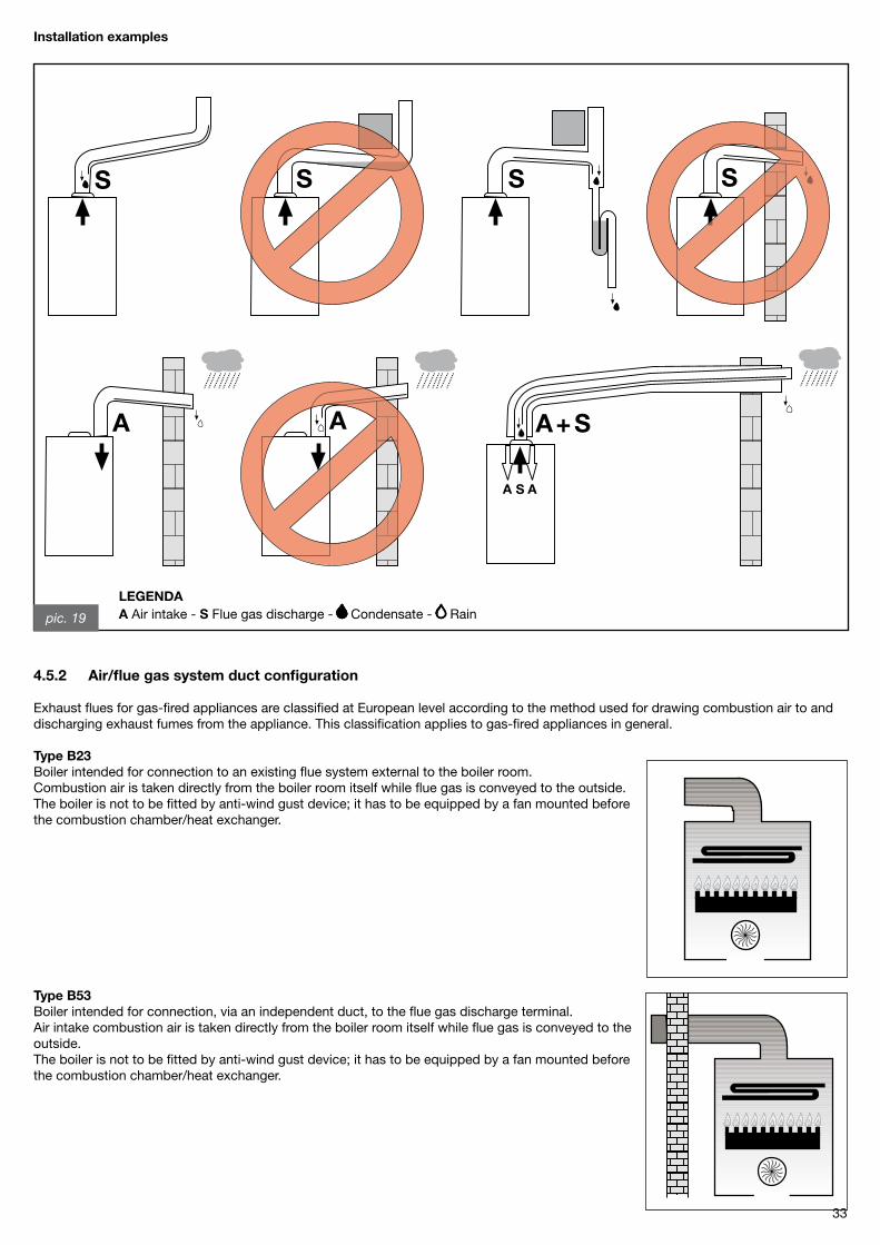
pic. 19
LEGENDAA Air intake - S Flue gas discharge - Condensate - Rain
Installation examples
4.5.2 Air/flue gas system duct configuration
Exhaust flues for gas-fired appliances are classified at European level according to the method used for drawing combustion air to and discharging exhaust fumes from the appliance. This classification applies to gas-fired appliances in general.
Type B23Boiler intended for connection to an existing flue system external to the boiler room. Combustion air is taken directly from the boiler room itself while flue gas is conveyed to the outside.The boiler is not to be fitted by anti-wind gust device; it has to be equipped by a fan mounted before the combustion chamber/heat exchanger.
Type B53Boiler intended for connection, via an independent duct, to the flue gas discharge terminal.Air intake combustion air is taken directly from the boiler room itself while flue gas is conveyed to the outside.The boiler is not to be fitted by anti-wind gust device; it has to be equipped by a fan mounted before the combustion chamber/heat exchanger.
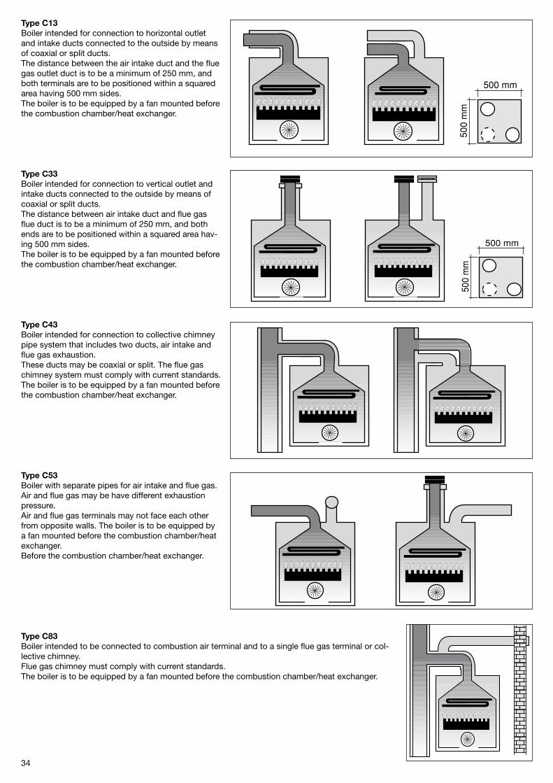
34
Type C13Boiler intended for connection to horizontal outlet and intake ducts connected to the outside by means of coaxial or split ducts.The distance between the air intake duct and the flue gas outlet duct is to be a minimum of �50 mm, and both terminals are to be positioned within a squared area having 500 mm sides.The boiler is to be equipped by a fan mounted before the combustion chamber/heat exchanger.
Type C33Boiler intended for connection to vertical outlet and intake ducts connected to the outside by means of coaxial or split ducts.The distance between air intake duct and flue gas flue duct is to be a minimum of �50 mm, and both ends are to be positioned within a squared area hav-ing 500 mm sides.The boiler is to be equipped by a fan mounted before the combustion chamber/heat exchanger.
Type C43Boiler intended for connection to collective chimney pipe system that includes two ducts, air intake and flue gas exhaustion.These ducts may be coaxial or split. The flue gas chimney system must comply with current standards.The boiler is to be equipped by a fan mounted before the combustion chamber/heat exchanger.
Type C53Boiler with separate pipes for air intake and flue gas. Air and flue gas may be have different exhaustion pressure.Air and flue gas terminals may not face each other from opposite walls. The boiler is to be equipped by a fan mounted before the combustion chamber/heat exchanger.Before the combustion chamber/heat exchanger.
Type C83Boiler intended to be connected to combustion air terminal and to a single flue gas terminal or col-lective chimney.Flue gas chimney must comply with current standards.The boiler is to be equipped by a fan mounted before the combustion chamber/heat exchanger.
35
In order to ensure that the appliance functions correctly and efficiently, the flue connection between the boiler and the flue terminal must be made using original components specifically designed for condensing boilers.
Traditional flue components cannot be used for conveying exhaust fumes from condensing boilers, nor vice versa.
It is recommended that:- for the exhaust discharge duct, the entire length of the flue slopes upwards towards the exterior in order to facilitate the flow of condensate back to the combustion chamber, which has been specifically designed to collect and drain the acidic condensate;- for the air intake, the entire length of the duct slopes upwards towards the boiler to prevent the entry of rainwater, dust or foreign bodies into the pipe;- in the case where a horizontal coaxial system is installed, the coaxial terminal must be positioned horizontally in that the exhaust duct has been specifically designed with the required slope (Ø 60) and the air intake (Ø 100) has been suitably protected against the weather.
4.5.3 Ø 100/60 mm air/flue gas coaxial duct system
The below data are referred to air intake/flue gas discharge system, implemented with original, rigid and smooth ducts, delivered by the manufacturer.
Type C13
KC 24 and KR 24Minimum permissible length of horizontal coaxial pipes is 1 meter, without accounting for the first elbow connected to the boiler. Maximum permissible length of Ø 100/60 mm horizontal coaxial pipes is 9.5 meter not including the first elbow connected to the boiler.For each additional 1 meter straight pipe maximum permissible length is to be reduced by 1 meter.For each additional 90° elbow, maximum permissible length is to be reduced by 1 meter.For each additional 45° elbow, maximum permissible length is to be reduced by 0.5 meter.The wall terminal reduces maximum permissible length by 1.5 meters.The air intake duct is to be tilted by 1% toward its exit, in order to avoid rain water to enter it.
KC 28 and KR 28Minimum permissible length of horizontal coaxial pipes is 1 meter, without accounting for the first elbow connected to the boiler. Maximum permissible length of Ø 100/60 mm horizontal coaxial pipes is 7.5 meter not including the first elbow connected to the boiler.For each additional 1 meter straight pipe maximum permissible length is to be reduced by 1 meter.For each additional 90° elbow, maximum permissible length is to be reduced by 1 meter.For each additional 45° elbow, maximum permissible length is to be reduced by 0.5 meter.The wall terminal reduces maximum permissible length by 1.5 meters.The air intake duct is to be tilted by 1% toward its exit, in order to avoid rain water to enter it.
KC 32 and KR 32Minimum permissible length of horizontal coaxial pipes is 1 meter, without accounting for the first elbow connected to the boiler. Maximum permissible length of Ø 100/60 mm horizontal coaxial pipes is 6.5 meter not including the first elbow connected to the boiler.For each additional 1 meter straight pipe maximum permissible length is to be reduced by 1 meter.For each additional 90° elbow, maximum permissible length is to be reduced by 1 meter.For each additional 45° elbow, maximum permissible length is to
be reduced by 0.5 meter.The wall terminal reduces maximum permissible length by 1.5 meters.The air intake duct is to be tilted by 1% toward its exit, in order to avoid rain water to enter it.
Type C33
KC 24 and KR 24Minimum permissible length of vertical coaxial pipes is 1 meter.Maximum permissible length of Ø 100/60 mm vertical coaxial pipes is 9.5 meters.For each additional 1 meter of straight pipe maximum permissible length is to be reduced by 1 meter.For each additional 90° elbow, maximum permissible length is to be reduced by 1 meter.For each additional 45° elbow, maximum permissible length is to be reduced by 0.5 meter.The roof terminal reduces maximum permissible length by 1.5 meters.
KC 28 and KR 28Minimum permissible length of vertical coaxial pipes is 1 meter.Maximum permissible length of Ø 100/60 mm vertical coaxial pipes is 7.5 meters.For each additional 1 meter of straight pipe maximum permissible length is to be reduced by 1 meter.For each additional 90° elbow, maximum permissible length is to be reduced by 1 meter.For each additional 45° elbow, maximum permissible length is to be reduced by 0.5 meter.The roof terminal reduces maximum permissible length by 1.5 meters.
KC 32 and KR 32Minimum permissible length of vertical coaxial pipes is 1 meter.Maximum permissible length of Ø 100/60 mm vertical coaxial pipes is 6.5 meters.For each additional 1 meter of straight pipe maximum permissible length is to be reduced by 1 meter.For each additional 90° elbow, maximum permissible length is to be reduced by 1 meter.For each additional 45° elbow, maximum permissible length is to be reduced by 0.5 meter.The roof terminal reduces maximum permissible length by 1.5 meters.
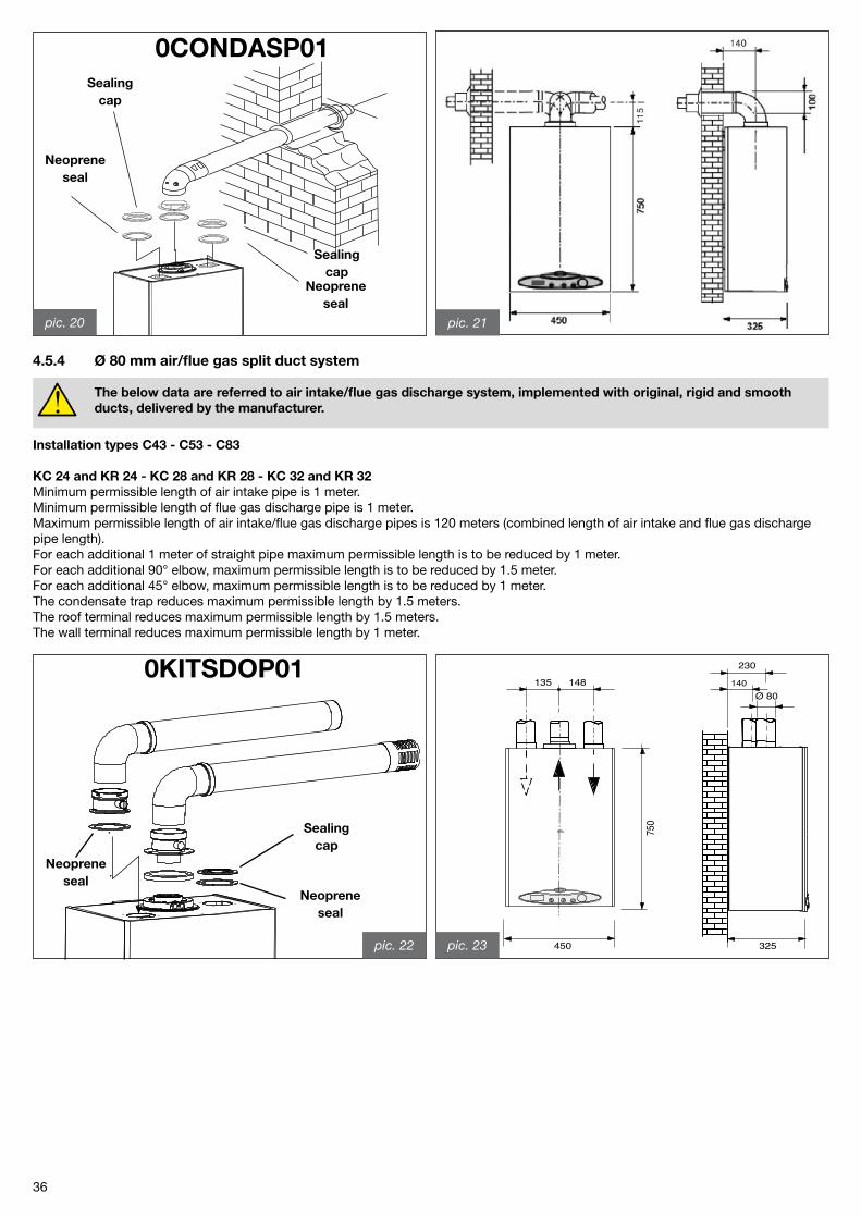
36
Neoprene seal
Neoprene seal
Sealing cap
Sealing cap
pic. 20 pic. 21
4.5.4 Ø 80 mm air/flue gas split duct system
The below data are referred to air intake/flue gas discharge system, implemented with original, rigid and smooth ducts, delivered by the manufacturer.
0CONDASP01
Sealing cap
Installation types C43 - C53 - C83
KC 24 and KR 24 - KC 28 and KR 28 - KC 32 and KR 32Minimum permissible length of air intake pipe is 1 meter.Minimum permissible length of flue gas discharge pipe is 1 meter.Maximum permissible length of air intake/flue gas discharge pipes is 1�0 meters (combined length of air intake and flue gas discharge pipe length).For each additional 1 meter of straight pipe maximum permissible length is to be reduced by 1 meter.For each additional 90° elbow, maximum permissible length is to be reduced by 1.5 meter.For each additional 45° elbow, maximum permissible length is to be reduced by 1 meter.The condensate trap reduces maximum permissible length by 1.5 meters.The roof terminal reduces maximum permissible length by 1.5 meters.The wall terminal reduces maximum permissible length by 1 meter.
Neoprene seal
Neoprene seal
0KITSDOP01
pic. 22 325450
750
230
140Ø 80
148135
pic. 23
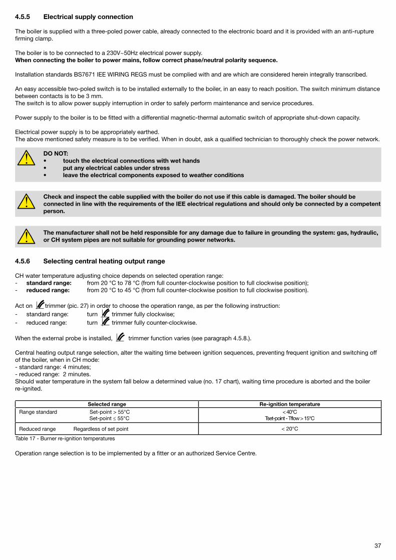
37
4.5.5 Electrical supply connection
The boiler is supplied with a three-poled power cable, already connected to the electronic board and it is provided with an anti-rupture firming clamp.
The boiler is to be connected to a �30V~50Hz electrical power supply.When connecting the boiler to power mains, follow correct phase/neutral polarity sequence.
Installation standards BS7671 IEE WIRING REGS must be complied with and are which are considered herein integrally transcribed.
An easy accessible two-poled switch is to be installed externally to the boiler, in an easy to reach position. The switch minimum distance between contacts is to be 3 mm.The switch is to allow power supply interruption in order to safely perform maintenance and service procedures.
Power supply to the boiler is to be fitted with a differential magnetic-thermal automatic switch of appropriate shut-down capacity.
Electrical power supply is to be appropriately earthed.The above mentioned safety measure is to be verified. When in doubt, ask a qualified technician to thoroughly check the power network.
DO NOT: • touch the electrical connections with wet hands • put any electrical cables under stress • leave the electrical components exposed to weather conditions
Check and inspect the cable supplied with the boiler do not use if this cable is damaged. The boiler should be connected in line with the requirements of the IEE electrical regulations and should only be connected by a competent person.
The manufacturer shall not be held responsible for any damage due to failure in grounding the system: gas, hydraulic, or CH system pipes are not suitable for grounding power networks.
4.5.6 Selecting central heating output range
CH water temperature adjusting choice depends on selected operation range:- standard range: from �0 °C to 78 °C (from full counter-clockwise position to full clockwise position);- reduced range: from �0 °C to 45 °C (from full counter-clockwise position to full clockwise position).
Act on trimmer (pic. �7) in order to choose the operation range, as per the following instruction:- standard range: turn trimmer fully clockwise;- reduced range: turn trimmer fully counter-clockwise.
When the external probe is installed, trimmer function varies (see paragraph 4.5.8.).
Central heating output range selection, alter the waiting time between ignition sequences, preventing frequent ignition and switching off of the boiler, when in CH mode:- standard range: 4 minutes;- reduced range: � minutes.Should water temperature in the system fall below a determined value (no. 17 chart), waiting time procedure is aborted and the boiler re-ignited.
Operation range selection is to be implemented by a fitter or an authorized Service Centre.
Selected range Re-ignition temperatureRange standard Set-point > 55°C
Set-point ≤ 55°C< 40°C
Tset-point - Tflow > 15°C
Reduced range Regardless of set point
< �0°C
Table 17 - Burner re-ignition temperatures
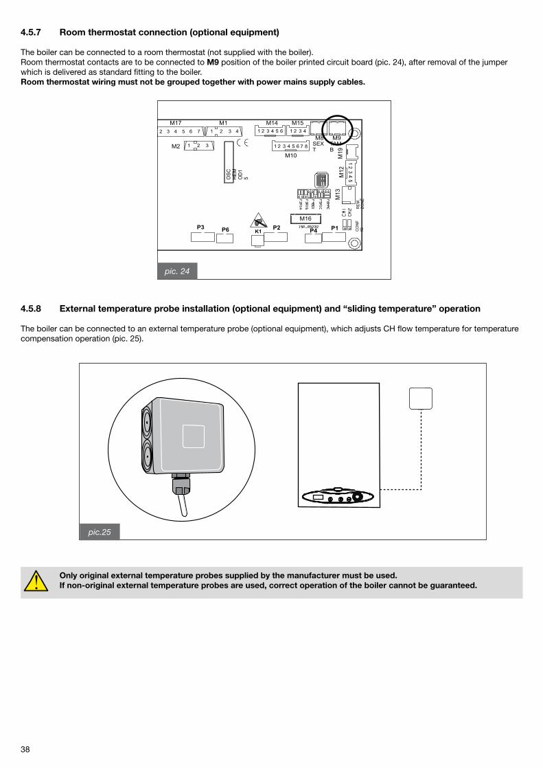
38
4.5.7 Room thermostat connection (optional equipment)
The boiler can be connected to a room thermostat (not supplied with the boiler).Room thermostat contacts are to be connected to M9 position of the boiler printed circuit board (pic. �4), after removal of the jumper which is delivered as standard fitting to the boiler.Room thermostat wiring must not be grouped together with power mains supply cables.
4.5.8 External temperature probe installation (optional equipment) and “sliding temperature” operation
The boiler can be connected to an external temperature probe (optional equipment), which adjusts CH flow temperature for temperature compensation operation (pic. �5).
Only original external temperature probes supplied by the manufacturer must be used. If non-original external temperature probes are used, correct operation of the boiler cannot be guaranteed.
pic. 24
pic.25
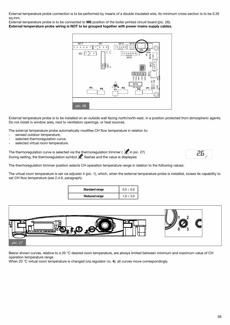
39
External temperature probe connection is to be performed by means of a double insulated wire, its minimum cross-section is to be 0.35 sq.mm.External temperature probe is to be connected to M8 position of the boiler printed circuit board (pic. �6).External temperature probe wiring is NOT to be grouped together with power mains supply cables.
External temperature probe is to be installed on an outside wall facing north/north-east, in a position protected from atmospheric agents. Do not install in window area, next to ventilation openings, or heat sources.
The external temperature probe automatically modifies CH flow temperature in relation to:- sensed outdoor temperature;- selected thermoregulation curve;- selected virtual room temperature.
The thermoregulation curve is selected via the thermoregulation trimmer ( in pic. �7)During setting, the thermoregulation symbol flashes and the value is displayed.
The thermoregulation trimmer position selects CH operation temperature range in relation to the following values: The virtual room temperature is set via adjuster 4 (pic. 1), which, when the external temperature probe is installed, looses its capability to set CH flow temperature (see �.4.6. paragraph).
Below shown curves, relative to a �0 °C desired room temperature, are always limited between minimum and maximum value of CH operation temperature range.When �0 °C virtual room temperature is changed (via regulator no. 4), all curves move correspondingly.
pic. 26
Standard range 0,0 ÷ 0,9
Reduced range 1,0 ÷ 3,0
pic. 27
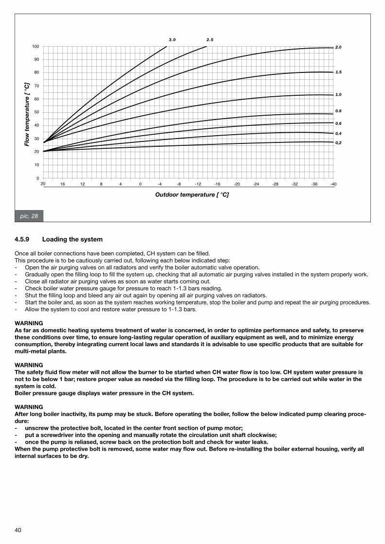
40
4.5.9 Loading the system
Once all boiler connections have been completed, CH system can be filled.This procedure is to be cautiously carried out, following each below indicated step:- Open the air purging valves on all radiators and verify the boiler automatic valve operation.- Gradually open the filling loop to fill the system up, checking that all automatic air purging valves installed in the system properly work.- Close all radiator air purging valves as soon as water starts coming out.- Check boiler water pressure gauge for pressure to reach 1-1.3 bars reading.- Shut the filling loop and bleed any air out again by opening all air purging valves on radiators.- Start the boiler and, as soon as the system reaches working temperature, stop the boiler and pump and repeat the air purging procedures.- Allow the system to cool and restore water pressure to 1-1.3 bars.
WARNINGAs far as domestic heating systems treatment of water is concerned, in order to optimize performance and safety, to preserve these conditions over time, to ensure long-lasting regular operation of auxiliary equipment as well, and to minimize energy consumption, thereby integrating current local laws and standards it is advisable to use specific products that are suitable for multi-metal plants.
WARNINGThe safety fluid flow meter will not allow the burner to be started when CH water flow is too low. CH system water pressure is not to be below 1 bar; restore proper value as needed via the filling loop. The procedure is to be carried out while water in the system is cold.Boiler pressure gauge displays water pressure in the CH system.
WARNINGAfter long boiler inactivity, its pump may be stuck. Before operating the boiler, follow the below indicated pump clearing proce-dure:- unscrew the protective bolt, located in the center front section of pump motor;- put a screwdriver into the opening and manually rotate the circulation unit shaft clockwise;- once the pump is reliased, screw back on the protection bolt and check for water leaks.When the pump protective bolt is removed, some water may flow out. Before re-installing the boiler external housing, verify all internal surfaces to be dry.
pic. 28
100
90
80
70
60
50
40
30
20
10
020 16 12 8 4 0 -4 -8 -12 -16 -20 -24 -28 -32 -36 -40
3.0 2.5
2.0
1.5
1.0
0.8
0.6
0.4
0,2
Outdoor temperature [ °C]
Flow
tem
per
atu
re [
°C
]
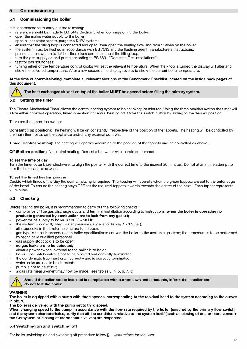
41
5 Commissioning
5.1 Commissioning the boiler
It is recommended to carry out the following:- reference should be made to BS 5449 Section 5 when commissioning the boiler;- open the mains water supply to the boiler;- open all hot water taps to purge the DHW system;- ensure that the filling loop is connected and open, then open the heating flow and return valves on the boiler;- the system must be flushed in accordance with BS 7593 and the flushing agent manufacturers instructions;- pressurise the system to 1.5 bar then close and disconnect the filling loop;- turn the gas supply on and purge according to BS 6891 “Domestic Gas Installations”;- test for gas soundness;- turning either of the temperature control knobs will set the relevant temperature. When the knob is turned the display will alter and show the selected temperature. After a few seconds the display reverts to show the current boiler temperature.
At the time of commissioning, complete all relevant sections of the Benchmark Checklist located on the inside back pages of this document.
The heat exchanger air vent on top of the boiler MUST be opened before filling the primary system.
5.2 Setting the timer
The Electro-Mechanical Timer allows the central heating system to be set every �0 minutes. Using the three position switch the timer will allow either constant operation, timed operation or central heating off. Move the switch button by sliding to the desired position.
There are three position switch:
Constant (Top position): The heating will be on constantly irrespective of the position of the tappets. The heating will be controlled by the main thermostat on the appliance and/or any external controls.
Timed (Central position): The heating will operate according to the position of the tappets and be controlled as above.
Off (Bottom position): No central heating. Domestic hot water will operate on demand.
To set the time of dayTurn the timer outer bezel clockwise, to align the pointer with the correct time to the nearest �0 minutes. Do not at any time attempt to turn the bezel anti-clockwise.
To set the timed heating programDecide which times of the day the central heating is required. The heating will operate when the green tappets are set to the outer edge of the bezel. To ensure the heating stays OFF set the required tappets inwards towards the centre of the bezel. Each tappet represents �0 minutes.
5.3 Checking
Before testing the boiler, it is recommended to carry out the following checks:- compliance of flue gas discharge ducts and terminal installation according to instructions: when the boiler is operating no products generated by combustion are to leak from any gasket;- power mains supply to boiler is �30 V ~ 50 Hz;- the system is correctly filled (water pressure gauge is to display 1 - 1.3 bar);- all stopcocks in the system piping are to be open;- gas type is to be in accordance to boiler specifications: convert the boiler to the available gas type; the procedure is to be performed by technically qualified personnel;- gas supply stopcock is to be open;- no gas leaks are to be detected;- electric power switch, external to the boiler is to be on;- boiler 3 bar safety valve is not to be blocked and correctly terminated;- the condensate trap must drain correctly and is correctly terminated;- water leaks are not to be detected;- pump is not to be stuck;- a gas rate measurement may now be made. (see tables 3, 4, 5, 6, 7, 8)
Should the boiler not be installed in compliance with current laws and standards, inform the installer and do not test the boiler.
WARNINGThe boiler is equipped with a pump with three speeds, corresponding to the residual head to the system according to the curves in pic. 9.The boiler is delivered with the pump set to third speed.When changing speed to the pump, in accordance with the flow rate required by the boiler (ensured by the primary flow switch) and the system characteristics, verify that all the conditions relative to the system itself (such as closing of one or more zones in the CH system or closing of thermostatic valves) are respected.
5.4 Switching on and switching off
For boiler switching on and switching off procedure follow § 1. Instructions for the User.
4�
6 Servicing
6.1 General Warnings
Before carrying out any type of maintenance operation, disconnect the appliance from the mains electricity supply and close the gas valve.
In order to guarantee the long life of the appliance and in accordance with the current gas safety regulations, only use original spare parts.
The frequency of the boiler maintenance must comply with current law and, nevertheless, should be carried out once a year.
6.2 Boiler inspection
Maintenance and repair procedures are strictly to be carried out by professionally qualified personnel.
The manufacturer recommends Customers to contact the Fondital Helpline UK for all maintenance and repairs, which are best trained for the purpose.
Appropriate heating unit maintenance ensures efficient operation, environment preservation, and safety for people, animals and objects.
The user is strongly advised to have the boiler serviced and repaired by one of the Manufacturer’s fully qualified and authorised Service Centres.Maintenance operations must be carried out at least once a year.
Routine maintenance must include a series of checks and cleaning operations.
Checks- General integrity of the boiler;- boiler and gas supply pipework for tightness;- gas supply pressure to boiler;- boiler ignition sequence;- boiler combustion parameters by analysis of flue gas;- flue gas system integrity, good state of preservation, and absence of leaks;- combustion fan correct operation;- general integrity of boiler safety devices;- absence of water leaks and oxidized areas on boiler couplings;- efficiency of the system safety valve;- expansion vessel loading pressure (1±0,� bar);- safety flow switch efficiency preventing low water pressure operation;- condensate discharge through the trap.
Cleaning operations:- General boiler internal areas;- gas nozzle;- air intake and flue gas exhaust system;- heat exchanger;- siphon and condensate discharge pipes.
When operating the boiler for the first time, also check:- boiler room suitability;- duct diameter and length in the flue gas system;- boiler installation in accordance to this “Installation use and maintenance” manual instructions.
Should the boiler not correctly operate, while not creating any danger to people, animals or property, inform the Fondital hel-pline UK both verbally and in writing.
After servicing, complete the relevant Service Interval Record section of the Benchmark Checklist located on the inside back pages of this document.
6.3 Combustion analysis
The boiler combustion parameter check to assess efficiency and products of combustion must be performed in accordance with the ap-plicable laws and regulations.
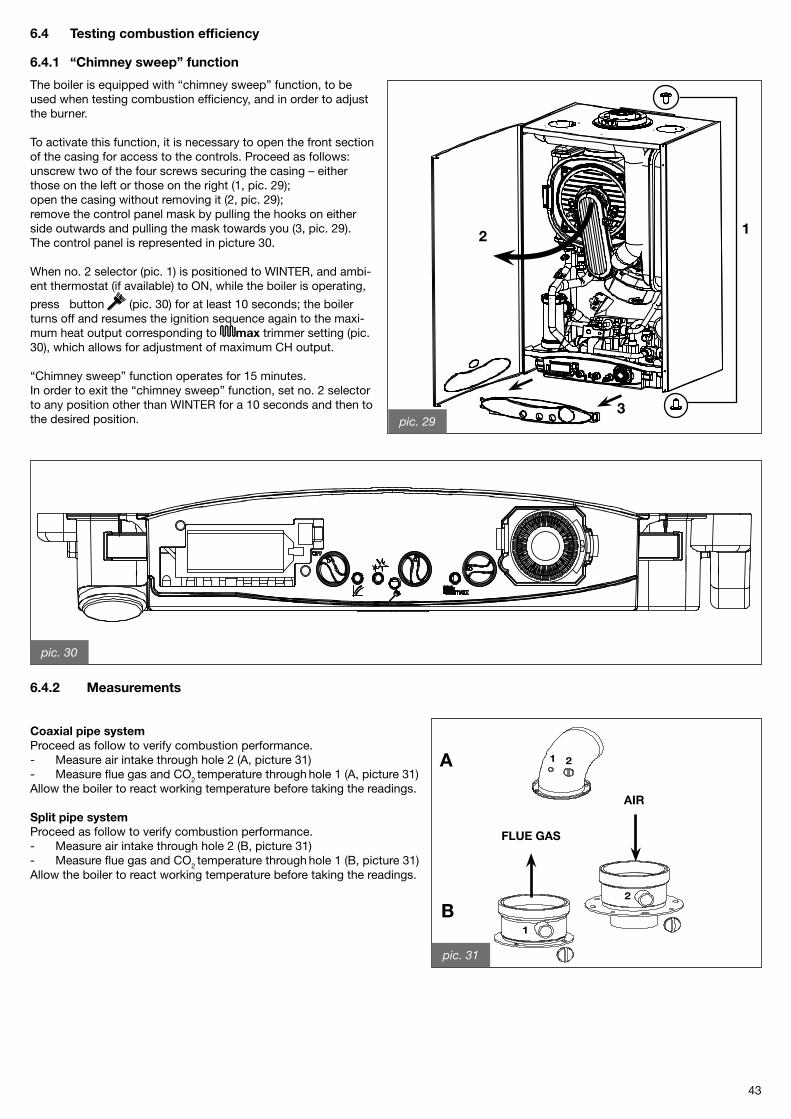
43
6.4 Testing combustion efficiency
6.4.1 “Chimney sweep” function
12
3
The boiler is equipped with “chimney sweep” function, to be used when testing combustion efficiency, and in order to adjust the burner.
To activate this function, it is necessary to open the front section of the casing for access to the controls. Proceed as follows:unscrew two of the four screws securing the casing – either those on the left or those on the right (1, pic. �9);open the casing without removing it (�, pic. �9);remove the control panel mask by pulling the hooks on either side outwards and pulling the mask towards you (3, pic. �9). The control panel is represented in picture 30.
When no. � selector (pic. 1) is positioned to WINTER, and ambi-ent thermostat (if available) to ON, while the boiler is operating,
press button (pic. 30) for at least 10 seconds; the boiler turns off and resumes the ignition sequence again to the maxi-mum heat output corresponding to max trimmer setting (pic. 30), which allows for adjustment of maximum CH output.
“Chimney sweep” function operates for 15 minutes.In order to exit the “chimney sweep” function, set no. � selector to any position other than WINTER for a 10 seconds and then to the desired position. pic. 29
pic. 30
6.4.2 Measurements
Coaxial pipe systemProceed as follow to verify combustion performance.- Measure air intake through hole � (A, picture 31)- Measure flue gas and CO� temperature through hole 1 (A, picture 31)Allow the boiler to react working temperature before taking the readings.
Split pipe systemProceed as follow to verify combustion performance.- Measure air intake through hole � (B, picture 31)- Measure flue gas and CO� temperature through hole 1 (B, picture 31)Allow the boiler to react working temperature before taking the readings.
1
2
1 2
AIR
FLUE GAS
B
A
pic. 31
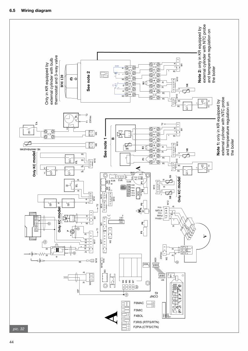
44
Onl
y in
KR
eq
uip
ped
by
exte
rnal
cyl
ind
er w
ith b
ulb
th
erm
ost
at a
nd 3
-way
val
ve
See
no
te 2
No
te 2
: onl
y in
KR
eq
uip
ped
by
exte
rnal
cyl
ind
er w
ith N
TC
pro
be
and
tem
per
atur
e re
gul
atio
n o
n th
e b
oile
r
See
no
te 1
No
te 1
: onl
y in
KR
eq
uip
ped
by
exte
rnal
cyl
ind
er w
ith N
TC
pro
be
and
tem
per
atur
e re
gul
atio
n o
n th
e b
oile
r
On
ly K
C m
od
el
On
ly K
C m
od
el
On
ly K
C m
od
el
pic. 32
6.5 Wiring diagram
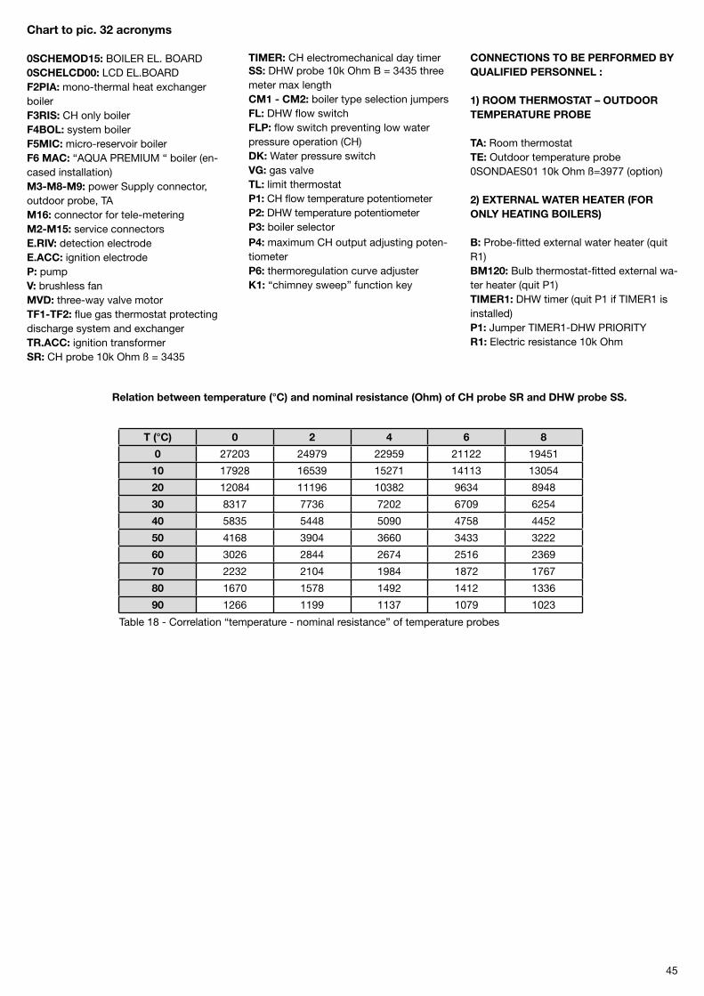
45
T (°C) 0 2 4 6 8
0 �7�03 �4979 ��959 �11�� 19451
10 179�8 16539 15�71 14113 13054
20 1�084 11196 1038� 9634 8948
30 8317 7736 7�0� 6709 6�54
40 5835 5448 5090 4758 445�
50 4168 3904 3660 3433 3���
60 30�6 �844 �674 �516 �369
70 ��3� �104 1984 187� 1767
80 1670 1578 149� 141� 1336
90 1�66 1199 1137 1079 10�3
Table 18 - Correlation “temperature - nominal resistance” of temperature probes
Chart to pic. 32 acronyms 0SCHEMOD15: BOILER EL. BOARD0SCHELCD00: LCD EL.BOARDF2PIA: mono-thermal heat exchanger boilerF3RIS: CH only boilerF4BOL: system boilerF5MIC: micro-reservoir boilerF6 MAC: “AQUA PREMIUM “ boiler (en-cased installation)M3-M8-M9: power Supply connector, outdoor probe, TAM16: connector for tele-meteringM2-M15: service connectorsE.RIV: detection electrodeE.ACC: ignition electrodeP: pumpV: brushless fanMVD: three-way valve motorTF1-TF2: flue gas thermostat protecting discharge system and exchangerTR.ACC: ignition transformerSR: CH probe 10k Ohm ß = 3435
TIMER: CH electromechanical day timerSS: DHW probe 10k Ohm B = 3435 three meter max lengthCM1 - CM2: boiler type selection jumpersFL: DHW flow switchFLP: flow switch preventing low water pressure operation (CH)DK: Water pressure switchVG: gas valveTL: limit thermostatP1: CH flow temperature potentiometerP2: DHW temperature potentiometerP3: boiler selectorP4: maximum CH output adjusting poten-tiometerP6: thermoregulation curve adjusterK1: “chimney sweep” function key
CONNECTIONS TO BE PERFORMED BY QUALIFIED PERSONNEL :
1) ROOM THERMOSTAT – OUTDOOR TEMPERATURE PROBE
TA: Room thermostatTE: Outdoor temperature probe 0SONDAES01 10k Ohm ß=3977 (option)
2) EXTERNAL WATER HEATER (FOR ONLY HEATING BOILERS)
B: Probe-fitted external water heater (quit R1)BM120: Bulb thermostat-fitted external wa-ter heater (quit P1)TIMER1: DHW timer (quit P1 if TIMER1 is installed)P1: Jumper TIMER1-DHW PRIORITYR1: Electric resistance 10k Ohm
Relation between temperature (°C) and nominal resistance (Ohm) of CH probe SR and DHW probe SS.

46
7 Spare part list
pic. 33
KC model
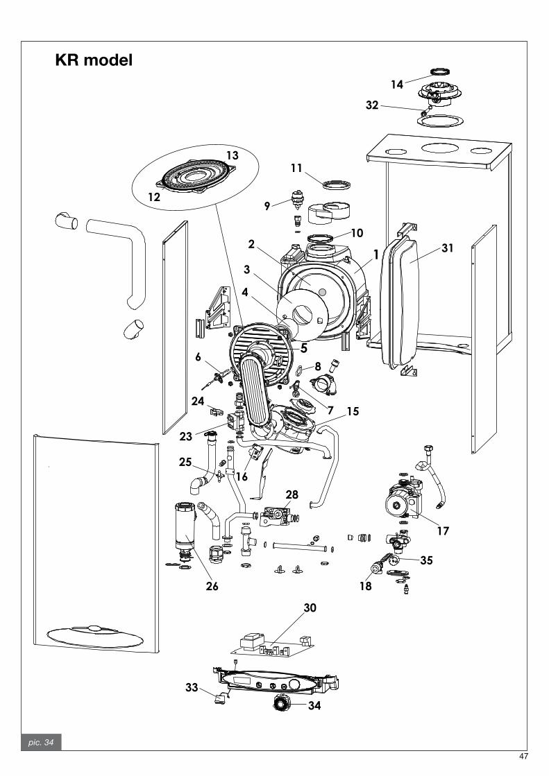
47
pic. 34
KR model
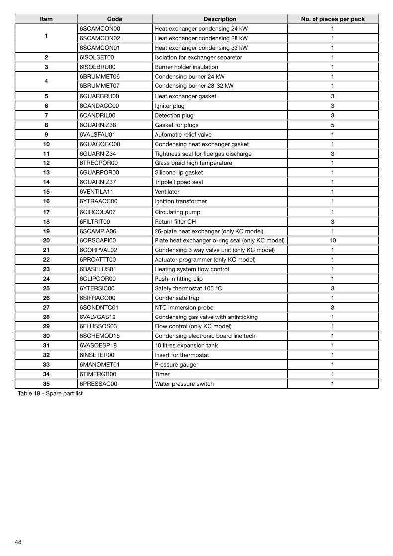
48
Item Code Description No. of pieces per pack
16SCAMCON00 Heat exchanger condensing �4 kW 1
6SCAMCON0� Heat exchanger condensing �8 kW 1
6SCAMCON01 Heat exchanger condensing 3� kW 1
2 6ISOLSET00 Isolation for exchanger separetor 1
3 6ISOLBRU00 Burner holder insulation 1
46BRUMMET06 Condensing burner �4 kW 1
6BRUMMET07 Condensing burner �8-3� kW 1
5 6GUARBRU00 Heat exchanger gasket 3
6 6CANDACC00 Igniter plug 3
7 6CANDRIL00 Detection plug 3
8 6GUARNIZ38 Gasket for plugs 5
9 6VALSFAU01 Automatic relief valve 1
10 6GUACOCO00 Condensing heat exchanger gasket 1
11 6GUARNIZ34 Tightness seal for flue gas discharge 3
12 6TRECPOR00 Glass braid high temperature 1
13 6GUARPOR00 Silicone lip gasket 1
14 6GUARNIZ37 Tripple lipped seal 1
15 6VENTILA11 Ventilator 1
16 6YTRAACC00 Ignition transformer 1
17 6CIRCOLA07 Circulating pump 1
18 6FILTRIT00 Return filter CH 3
19 6SCAMPIA06 �6-plate heat exchanger (only KC model) 1
20 6ORSCAPI00 Plate heat exchanger o-ring seal (only KC model) 10
21 6CORPVAL0� Condensing 3 way valve unit (only KC model) 1
22 6PROATTT00 Actuator programmer (only KC model) 1
23 6BASFLUS01 Heating system flow control 1
24 6CLIPCOR00 Push-in fitting clip 1
25 6YTERSIC00 Safety thermostat 105 °C 3
26 6SIFRACO00 Condensate trap 1
27 6SONDNTC01 NTC immersion probe 3
28 6VALVGAS1� Condensing gas valve with antisticking 1
29 6FLUSSOS03 Flow control (only KC model) 1
30 6SCHEMOD15 Condensing electronic board line tech 1
31 6VASOESP18 10 litres expansion tank 1
32 6INSETER00 Insert for thermostat 1
33 6MANOMET01 Pressure gauge 1
34 6TIMERGB00 Timer 1
35 6PRESSAC00 Water pressure switch 1
Table 19 - Spare part list
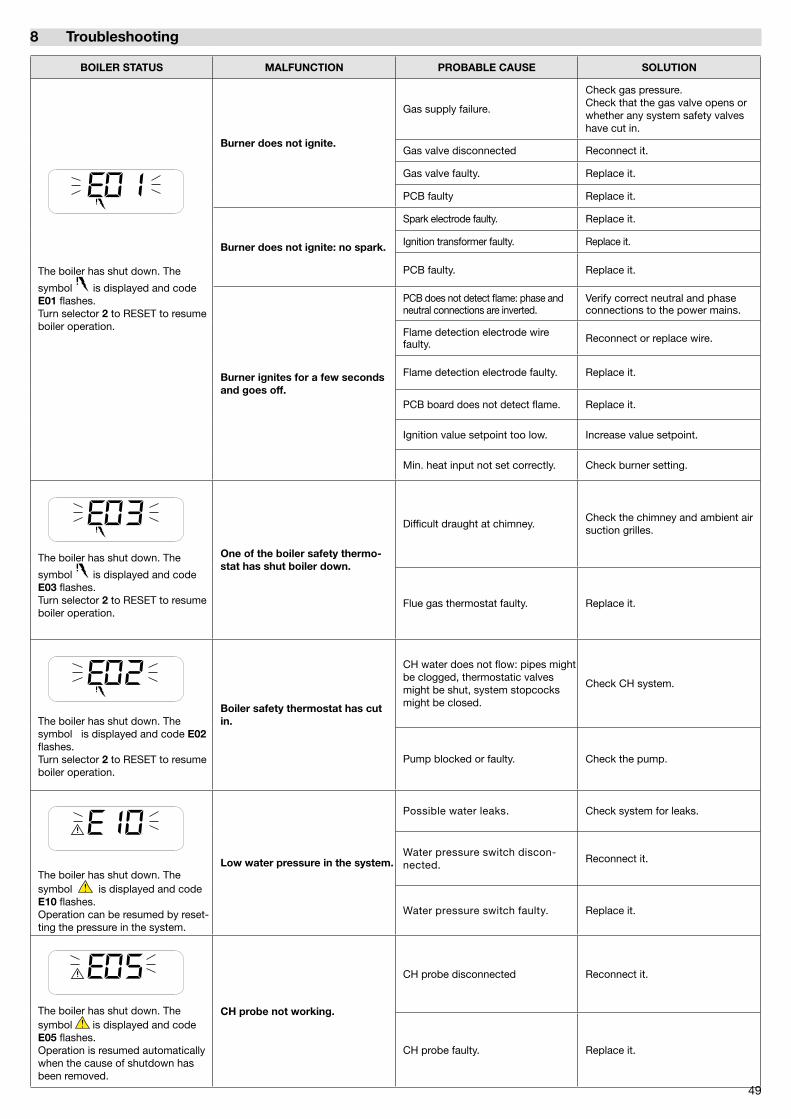
49
BOILER STATUS MALFUNCTION PROBABLE CAUSE SOLUTION
The boiler has shut down. The
symbol is displayed and code E01 flashes.Turn selector 2 to RESET to resume boiler operation.
Burner does not ignite.
Gas supply failure.
Check gas pressure.Check that the gas valve opens or whether any system safety valves have cut in.
Gas valve disconnected Reconnect it.
Gas valve faulty. Replace it.
PCB faulty Replace it.
Burner does not ignite: no spark.
Spark electrode faulty. Replace it.
Ignition transformer faulty. Replace it.
PCB faulty. Replace it.
Burner ignites for a few seconds and goes off.
PCB does not detect flame: phase and neutral connections are inverted.
Verify correct neutral and phase connections to the power mains.
Flame detection electrode wire faulty. Reconnect or replace wire.
Flame detection electrode faulty. Replace it.
PCB board does not detect flame. Replace it.
Ignition value setpoint too low. Increase value setpoint.
Min. heat input not set correctly. Check burner setting.
The boiler has shut down. The
symbol is displayed and code E03 flashes.Turn selector 2 to RESET to resume boiler operation.
One of the boiler safety thermo-stat has shut boiler down.
Difficult draught at chimney.Check the chimney and ambient air suction grilles.
Flue gas thermostat faulty. Replace it.
The boiler has shut down. The symbol is displayed and code E02 flashes.Turn selector 2 to RESET to resume boiler operation.
Boiler safety thermostat has cut in.
CH water does not flow: pipes might be clogged, thermostatic valves might be shut, system stopcocks might be closed.
Check CH system.
Pump blocked or faulty. Check the pump.
The boiler has shut down. The symbol is displayed and code E10 flashes.Operation can be resumed by reset-ting the pressure in the system.
Low water pressure in the system.
Possible water leaks. Check system for leaks.
Water pressure switch discon-nected.
Reconnect it.
Water pressure switch faulty. Replace it.
The boiler has shut down. The symbol is displayed and code E05 flashes.Operation is resumed automatically when the cause of shutdown has been removed.
CH probe not working.
CH probe disconnected Reconnect it.
CH probe faulty. Replace it.
8 Troubleshooting
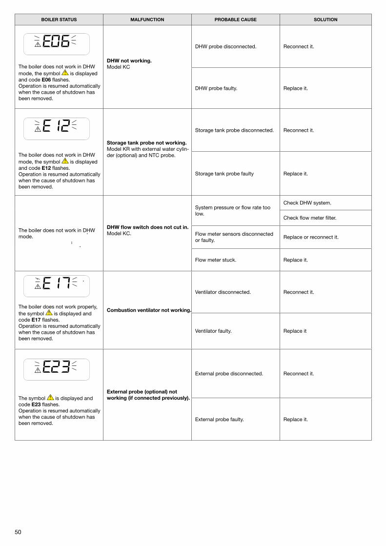
50
BOILER STATUS MALFUNCTION PROBABLE CAUSE SOLUTION
The boiler does not work in DHW mode, the symbol is displayed and code E06 flashes.Operation is resumed automatically when the cause of shutdown has been removed.
DHW not working.Model KC
DHW probe disconnected. Reconnect it.
DHW probe faulty. Replace it.
The boiler does not work in DHW mode, the symbol is displayed and code E12 flashes.Operation is resumed automatically when the cause of shutdown has been removed.
Storage tank probe not working.Model KR with external water cylin-der (optional) and NTC probe.
Storage tank probe disconnected. Reconnect it.
Storage tank probe faulty Replace it.
The boiler does not work in DHW mode.
DHW flow switch does not cut in. Model KC.
System pressure or flow rate too low.
Check DHW system.
Check flow meter filter.
Flow meter sensors disconnected or faulty.
Replace or reconnect it.
Flow meter stuck. Replace it.
The boiler does not work properly, the symbol is displayed and code E17 flashes.Operation is resumed automatically when the cause of shutdown has been removed.
Combustion ventilator not working.
Ventilator disconnected. Reconnect it.
Ventilator faulty. Replace it
The symbol is displayed and code E23 flashes.Operation is resumed automatically when the cause of shutdown has been removed.
External probe (optional) not working (if connected previously).
External probe disconnected. Reconnect it.
External probe faulty. Replace it.
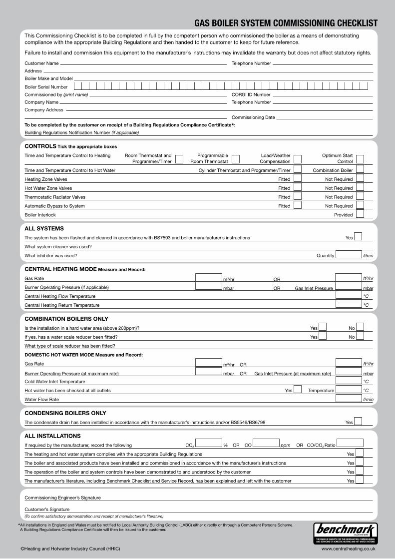
51
GAS Boiler SyStem CommiSSioNiNG CHeCKliSt
CONTROLS Tick the appropriate boxes
Time and Temperature Control to Heating Room Thermostat and Programmable Load/Weather Optimum Start Programmer/Timer Room Thermostat Compensation Control
Time and Temperature Control to Hot Water Cylinder Thermostat and Programmer/Timer Combination Boiler
Heating Zone Valves Fitted Not Required
Hot Water Zone Valves Fitted Not Required
Thermostatic Radiator Valves Fitted Not Required
Automatic Bypass to System Fitted Not Required
Boiler Interlock Provided
ALL SYSTEMS
The system has been flushed and cleaned in accordance with BS7593 and boiler manufacturer’s instructions Yes
What system cleaner was used?
What inhibitor was used? Quantity litres
CENTRAL HEATING MODE Measure and Record:
Gas Rate m3/hr OR ft3/hr
Burner Operating Pressure (if applicable) mbar OR Gas Inlet Pressure mbar
Central Heating Flow Temperature °C
Central Heating Return Temperature °C
COMBINATION BOILERS ONLY
Is the installation in a hard water area (above 200ppm)? Yes No
If yes, has a water scale reducer been fitted? Yes No
What type of scale reducer has been fitted?
DOMESTIC HOT WATER MODE Measure and Record:
Gas Rate m3/hr OR ft3/hr
Burner Operating Pressure (at maximum rate) mbar OR Gas Inlet Pressure (at maximum rate) mbar
Cold Water Inlet Temperature °C
Hot water has been checked at all outlets Yes Temperature °C
Water Flow Rate l/min
CONDENSING BOILERS ONLY
The condensate drain has been installed in accordance with the manufacturer’s instructions and/or BS5546/BS6798 Yes
ALL INSTALLATIONS
If required by the manufacturer, record the following CO2 % OR CO ppm OR CO/CO2 Ratio
The heating and hot water system complies with the appropriate Building Regulations Yes
The boiler and associated products have been installed and commissioned in accordance with the manufacturer’s instructions Yes
The operation of the boiler and system controls have been demonstrated to and understood by the customer Yes
The manufacturer’s literature, including Benchmark Checklist and Service Record, has been explained and left with the customer Yes
*All installations in England and Wales must be notified to Local Authority Building Control (LABC) either directly or through a Competent Persons Scheme. A Building Regulations Compliance Certificate will then be issued to the customer.
©Heating and Hotwater Industry Council (HHIC) www.centralheating.co.uk
Commissioning Engineer’s Signature
Customer’s Signature(To confirm satisfactory demonstration and receipt of manufacturer’s literature)
This Commissioning Checklist is to be completed in full by the competent person who commissioned the boiler as a means of demonstrating compliance with the appropriate Building Regulations and then handed to the customer to keep for future reference.
Failure to install and commission this equipment to the manufacturer’s instructions may invalidate the warranty but does not affect statutory rights.
Customer Name Telephone Number
Address
Boiler Make and Model
Boiler Serial Number
Commissioned by (print name) CORGI ID Number
Company Name Telephone Number
Company Address
Commissioning Date
To be completed by the customer on receipt of a Building Regulations Compliance Certificate*:
Building Regulations Notification Number (if applicable)
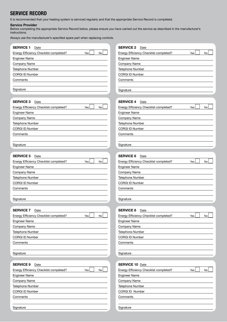
5�
SERVICE RECORDIt is recommended that your heating system is serviced regularly and that the appropriate Service Record is completed.
Service ProviderBefore completing the appropriate Service Record below, please ensure you have carried out the service as described in the manufacturer’sinstructions.
Always use the manufacturer’s specified spare part when replacing controls.
SERVICE 1 Date
Energy Efficiency Checklist completed? Yes No
Engineer Name
Company Name
Telephone Number
CORGI ID Number
Comments
Signature
SERVICE 3 Date
Energy Efficiency Checklist completed? Yes No
Engineer Name
Company Name
Telephone Number
CORGI ID Number
Comments
Signature
SERVICE 5 Date
Energy Efficiency Checklist completed? Yes No
Engineer Name
Company Name
Telephone Number
CORGI ID Number
Comments
Signature
SERVICE 7 Date
Energy Efficiency Checklist completed? Yes No
Engineer Name
Company Name
Telephone Number
CORGI ID Number
Comments
Signature
SERVICE 9 Date
Energy Efficiency Checklist completed? Yes No
Engineer Name
Company Name
Telephone Number
CORGI ID Number
Comments
Signature
SERVICE 2 Date
Energy Efficiency Checklist completed? Yes No
Engineer Name
Company Name
Telephone Number
CORGI ID Number
Comments
Signature
SERVICE 4 Date
Energy Efficiency Checklist completed? Yes No
Engineer Name
Company Name
Telephone Number
CORGI ID Number
Comments
Signature
SERVICE 6 Date
Energy Efficiency Checklist completed? Yes No
Engineer Name
Company Name
Telephone Number
CORGI ID Number
Comments
Signature
SERVICE 8 Date
Energy Efficiency Checklist completed? Yes No
Engineer Name
Company Name
Telephone Number
CORGI ID Number
Comments
Signature
SERVICE 10 Date
Energy Efficiency Checklist completed? Yes No
Engineer Name
Company Name
Telephone Number
CORGI ID Number
Comments
Signature

53

54


Fondital S.p.A.25078 VESTONE (Brescia) Italia - Via Mocenigo, 123
Tel. 0365/878.31 - Fax 0365/596.257e mail: [email protected] - www.fondital.it
The manufacturer reserves the right to implement any necessary and/or usefulvariation to products, without modifying fundamental characteristics.
Uff. Pubblicità Fondital IST 03 C xxx - 01 Gennaio 2008 (01/2008)
COD. 0xxxxxxx00
Fondital UK Helpline 08700 34 88 20