tablet format - content.datarunners.net
TRANSCRIPT
Self Study Program 871213C
The ID.4 Electrical and Communication SystemsTablet Format

Volkswagen Group Canada, INC.
Volkswagen Canada Academy, Service Training
SSP #871213C, The ID.4 Electrical and Communication Systems (Tablet Edition)
Ajax, ON, Canada
Edited September 2021
V. 001 / en-CA
Technical status: 06.2021
©2021 Volkswagen Group Canada, INC.
All rights reserved. All information contained in this document is based on the latest information available at the time of printing and is subject to the copyright and other intellectual property rights of Volkswagen Group Canada, INC, its affiliated companies and its licensors. All rights are reserved to make changes at any time without notice. No part of this document may be reproduced, stored in a retrieval system, or transmitted in any form or by any means, electronic, mechanical, photocopying recording or otherwise, nor may these materials be modified or reposted to other sites without the prior expressed written permission of the publisher.
All requests for permission to copy and redistribute should be referred to Volkswagen Group Canada, INC.
Trademarks: All brand names and product names used in this manual are trade names, service marks, trademarks, or registered trademarks; and are the property of their respective owners.
Introduction . . . . . . . . . . . . . . . . . . . . . . . . . . . . . . . . . . . . . . . . . . . . . . . . . . . . . . . . . . . . . . . . . 1
High-speed Communication Systems . . . . . . . . . . . . . . . . . . . . . . . . . . . . . . . . . . . . . . . . . . . 2
Lighting . . . . . . . . . . . . . . . . . . . . . . . . . . . . . . . . . . . . . . . . . . . . . . . . . . . . . . . . . . . . . . . . . . . 11
Energy Management . . . . . . . . . . . . . . . . . . . . . . . . . . . . . . . . . . . . . . . . . . . . . . . . . . . . . . . . 30
Terminal Control . . . . . . . . . . . . . . . . . . . . . . . . . . . . . . . . . . . . . . . . . . . . . . . . . . . . . . . . . . . . 34
Keyless Access (KESSY) . . . . . . . . . . . . . . . . . . . . . . . . . . . . . . . . . . . . . . . . . . . . . . . . . . . . . . 46
Infotainment . . . . . . . . . . . . . . . . . . . . . . . . . . . . . . . . . . . . . . . . . . . . . . . . . . . . . . . . . . . . . . . 53
Table of Contents
1
Introduction
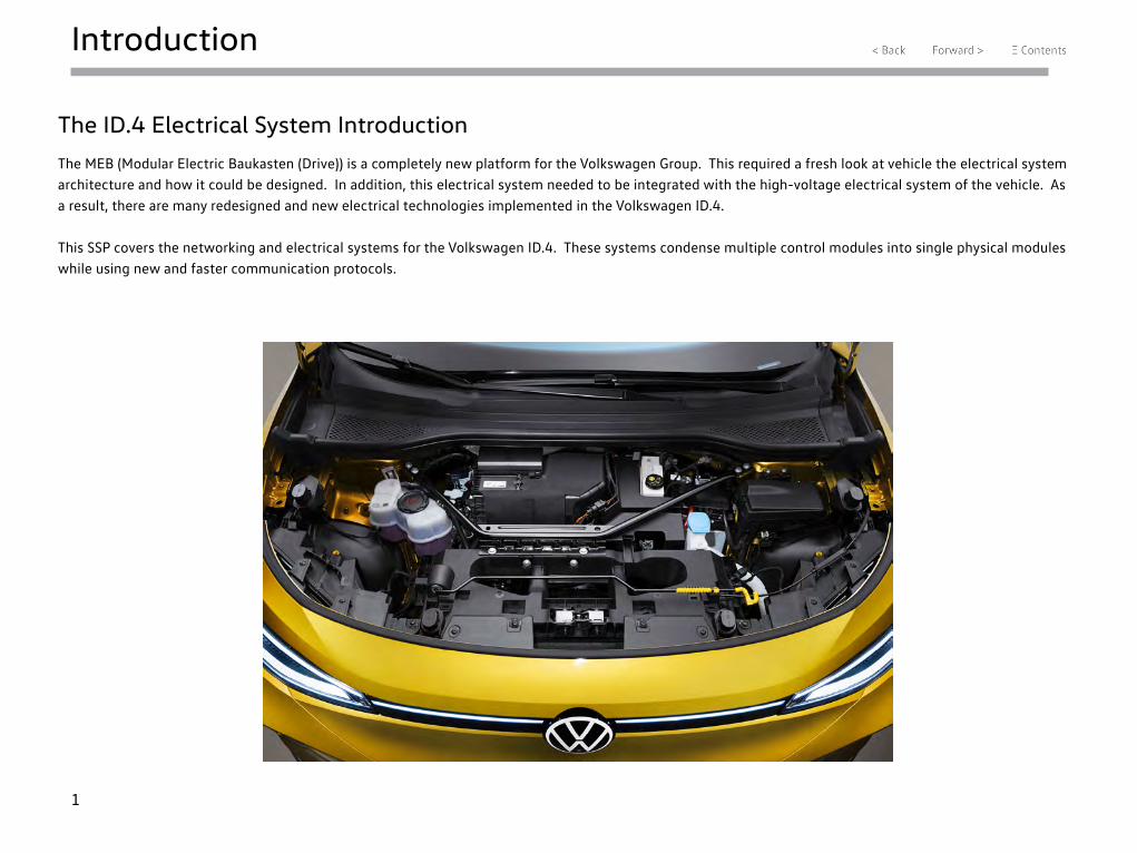
The ID.4 Electrical System Introduction
The MEB (Modular Electric Baukasten (Drive)) is a completely new platform for the Volkswagen Group. This required a fresh look at vehicle the electrical system architecture and how it could be designed. In addition, this electrical system needed to be integrated with the high-voltage electrical system of the vehicle. As a result, there are many redesigned and new electrical technologies implemented in the Volkswagen ID.4.
This SSP covers the networking and electrical systems for the Volkswagen ID.4. These systems condense multiple control modules into single physical modules while using new and faster communication protocols.
2
High Speed Communications
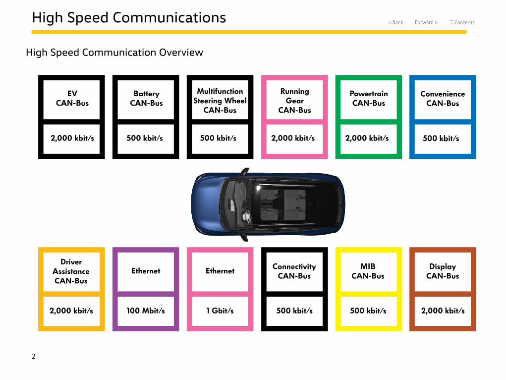
High Speed Communication Overview
EV CAN-Bus
2,000 kbit/s
Battery CAN-Bus
500 kbit/s
Multifunction Steering Wheel
CAN-Bus
500 kbit/s
Running Gear
CAN-Bus
2,000 kbit/s
Powertrain CAN-Bus
2,000 kbit/s
Convenience CAN-Bus
500 kbit/s
Driver Assistance CAN-Bus
2,000 kbit/s
Ethernet
100 Mbit/s
Ethernet
1 Gbit/s
Connectivity CAN-Bus
500 kbit/s
MIB CAN-Bus
500 kbit/s
Display CAN-Bus
2,000 kbit/s
3
High Speed Communications
CAN-Busses
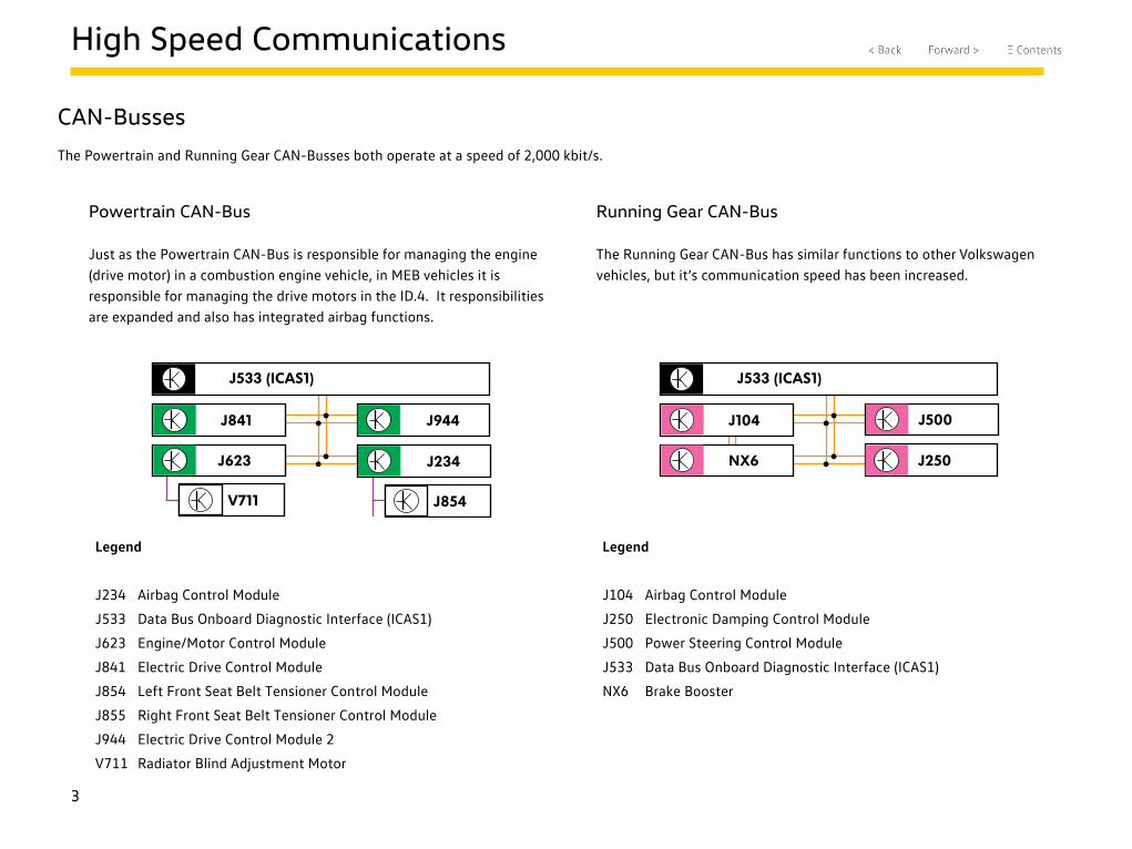
The Powertrain and Running Gear CAN-Busses both operate at a speed of 2,000 kbit/s.
J533 (ICAS1)
J841
J623
V711 J854
J855
J234
J944
J533 (ICAS1)
J500
J250NX6
J104
Powertrain CAN-Bus
Just as the Powertrain CAN-Bus is responsible for managing the engine (drive motor) in a combustion engine vehicle, in MEB vehicles it is responsible for managing the drive motors in the ID.4. It responsibilities are expanded and also has integrated airbag functions.
Running Gear CAN-Bus
The Running Gear CAN-Bus has similar functions to other Volkswagen vehicles, but it’s communication speed has been increased.
Legend
J234 Airbag Control Module
J533 Data Bus Onboard Diagnostic Interface (ICAS1)
J623 Engine/Motor Control Module
J841 Electric Drive Control Module
J854 Left Front Seat Belt Tensioner Control Module
J855 Right Front Seat Belt Tensioner Control Module
J944 Electric Drive Control Module 2
V711 Radiator Blind Adjustment Motor
Legend
J104 Airbag Control Module
J250 Electronic Damping Control Module
J500 Power Steering Control Module
J533 Data Bus Onboard Diagnostic Interface (ICAS1)
NX6 Brake Booster
4
High Speed Communications
Comfort and Convenience CAN-Bus
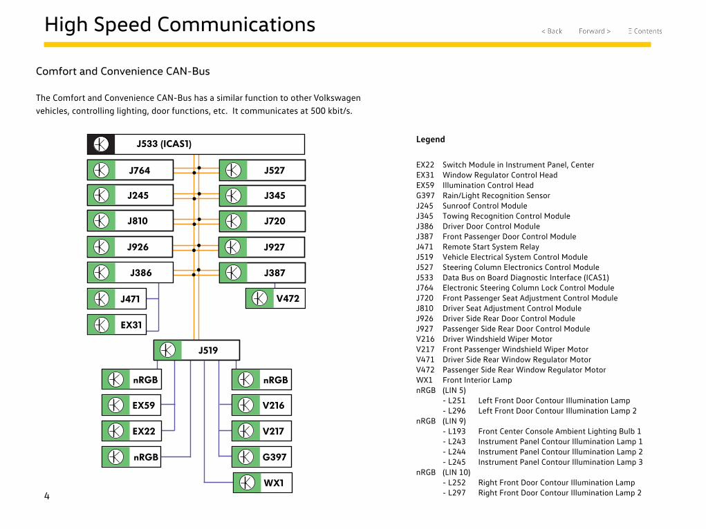
The Comfort and Convenience CAN-Bus has a similar function to other Volkswagen vehicles, controlling lighting, door functions, etc. It communicates at 500 kbit/s.
Legend
EX22 Switch Module in Instrument Panel, CenterEX31 Window Regulator Control HeadEX59 Illumination Control HeadG397 Rain/Light Recognition SensorJ245 Sunroof Control ModuleJ345 Towing Recognition Control ModuleJ386 Driver Door Control ModuleJ387 Front Passenger Door Control ModuleJ471 Remote Start System RelayJ519 Vehicle Electrical System Control ModuleJ527 Steering Column Electronics Control ModuleJ533 Data Bus on Board Diagnostic Interface (ICAS1)J764 Electronic Steering Column Lock Control ModuleJ720 Front Passenger Seat Adjustment Control ModuleJ810 Driver Seat Adjustment Control ModuleJ926 Driver Side Rear Door Control ModuleJ927 Passenger Side Rear Door Control ModuleV216 Driver Windshield Wiper MotorV217 Front Passenger Windshield Wiper MotorV471 Driver Side Rear Window Regulator MotorV472 Passenger Side Rear Window Regulator MotorWX1 Front Interior LampnRGB (LIN 5) - L251 Left Front Door Contour Illumination Lamp - L296 Left Front Door Contour Illumination Lamp 2nRGB (LIN 9) - L193 Front Center Console Ambient Lighting Bulb 1 - L243 Instrument Panel Contour Illumination Lamp 1 - L244 Instrument Panel Contour Illumination Lamp 2 - L245 Instrument Panel Contour Illumination Lamp 3nRGB (LIN 10) - L252 Right Front Door Contour Illumination Lamp - L297 Right Front Door Contour Illumination Lamp 2
J533 (ICAS1)
J386
V216
V217
J527
J245 J345
J764
J471
EX31
V472
J387
EX59
EX22
J519
nRGB nRGB
G397nRGB
WX1
J810 J720
J926 J927
5
High Speed Communications
J533 (ICAS1)
J1050A19
Z132
J1208J1212J1216
J840
G238 G395
G826
G827
G929
N636
N637
N638
G828
G829
N640
N641
N642
N643
N696
G805
G935
G1090
J126
J842
J848
J979
EV and Battery CAN-Busses
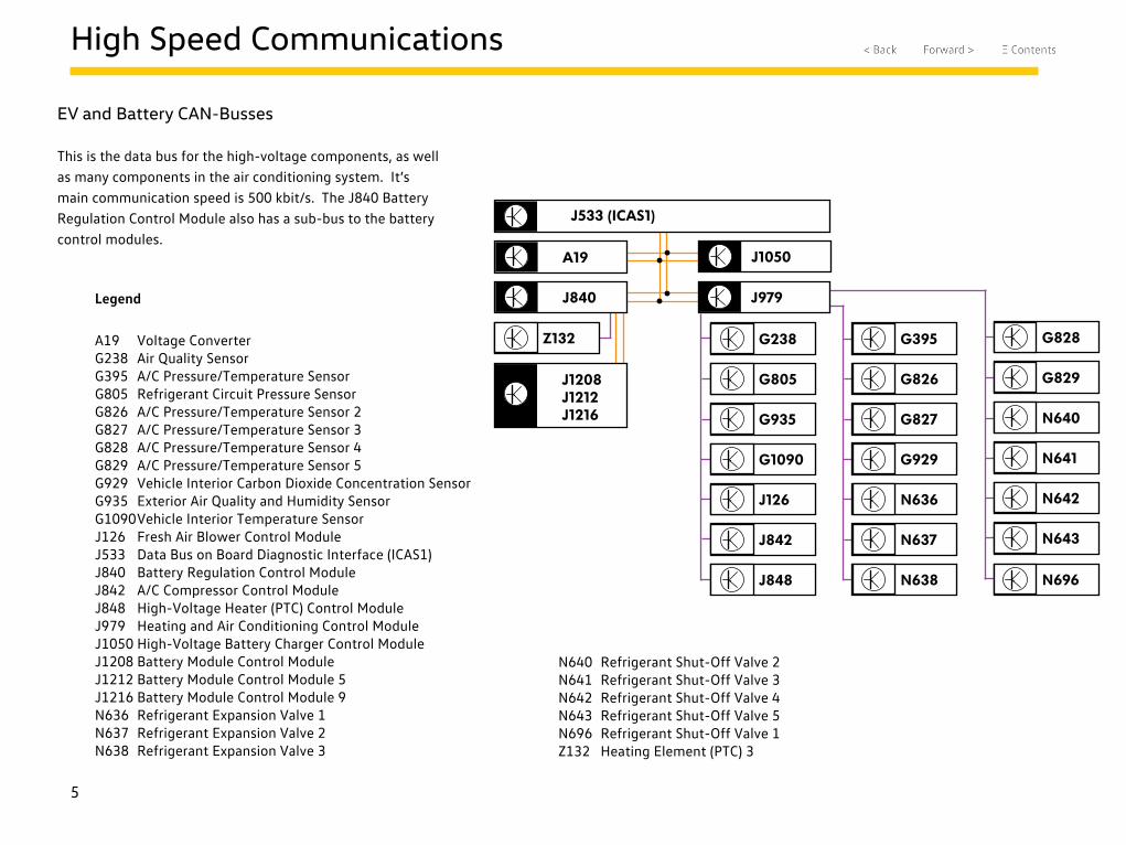
This is the data bus for the high-voltage components, as well as many components in the air conditioning system. It’s main communication speed is 500 kbit/s. The J840 Battery Regulation Control Module also has a sub-bus to the battery control modules.
Legend
A19 Voltage ConverterG238 Air Quality SensorG395 A/C Pressure/Temperature SensorG805 Refrigerant Circuit Pressure SensorG826 A/C Pressure/Temperature Sensor 2G827 A/C Pressure/Temperature Sensor 3G828 A/C Pressure/Temperature Sensor 4G829 A/C Pressure/Temperature Sensor 5G929 Vehicle Interior Carbon Dioxide Concentration SensorG935 Exterior Air Quality and Humidity SensorG1090 Vehicle Interior Temperature SensorJ126 Fresh Air Blower Control ModuleJ533 Data Bus on Board Diagnostic Interface (ICAS1)J840 Battery Regulation Control ModuleJ842 A/C Compressor Control ModuleJ848 High-Voltage Heater (PTC) Control ModuleJ979 Heating and Air Conditioning Control ModuleJ1050 High-Voltage Battery Charger Control ModuleJ1208 Battery Module Control ModuleJ1212 Battery Module Control Module 5J1216 Battery Module Control Module 9N636 Refrigerant Expansion Valve 1N637 Refrigerant Expansion Valve 2N638 Refrigerant Expansion Valve 3
N640 Refrigerant Shut-Off Valve 2N641 Refrigerant Shut-Off Valve 3N642 Refrigerant Shut-Off Valve 4N643 Refrigerant Shut-Off Valve 5N696 Refrigerant Shut-Off Valve 1Z132 Heating Element (PTC) 3
6
High Speed Communications
CAN-Busses
Multifunction Steering Wheel CAN-Bus
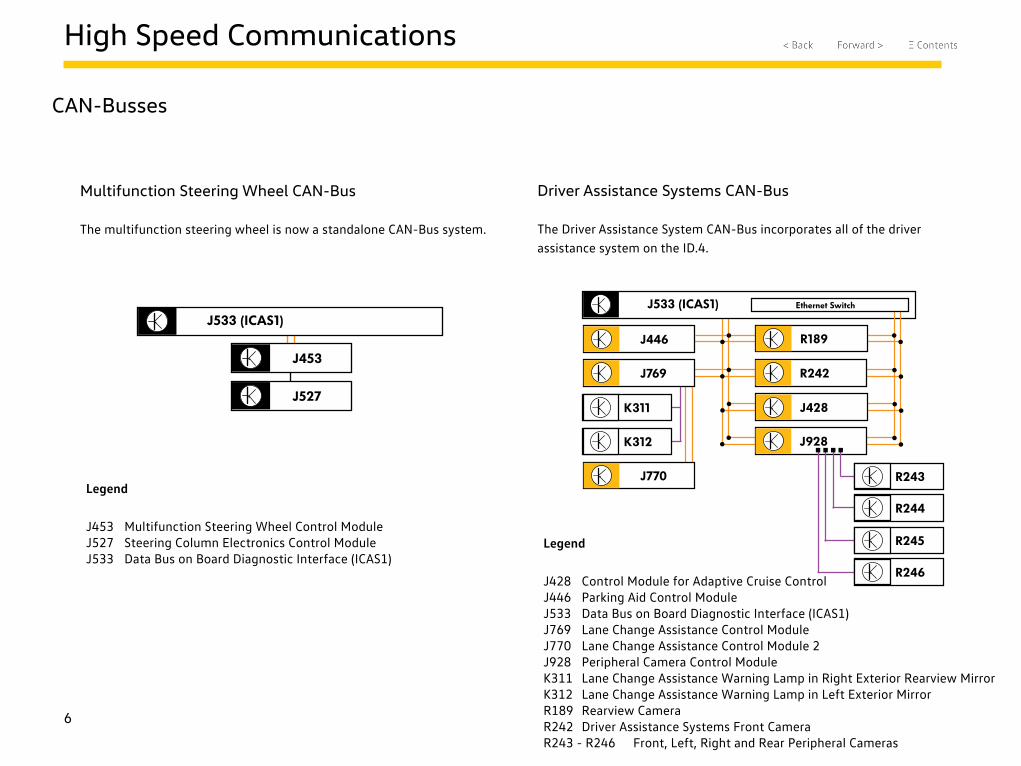
The multifunction steering wheel is now a standalone CAN-Bus system.
Legend
J453 Multifunction Steering Wheel Control ModuleJ527 Steering Column Electronics Control ModuleJ533 Data Bus on Board Diagnostic Interface (ICAS1)
Driver Assistance Systems CAN-Bus
The Driver Assistance System CAN-Bus incorporates all of the driver assistance system on the ID.4.
Legend
J428 Control Module for Adaptive Cruise ControlJ446 Parking Aid Control ModuleJ533 Data Bus on Board Diagnostic Interface (ICAS1)J769 Lane Change Assistance Control ModuleJ770 Lane Change Assistance Control Module 2J928 Peripheral Camera Control ModuleK311 Lane Change Assistance Warning Lamp in Right Exterior Rearview MirrorK312 Lane Change Assistance Warning Lamp in Left Exterior MirrorR189 Rearview CameraR242 Driver Assistance Systems Front CameraR243 - R246 Front, Left, Right and Rear Peripheral Cameras
J533 (ICAS1)
J453
J527
J533 (ICAS1)
R189
R242
J446
J428K311
K312
J769
Ethernet Switch
J928
R243
R244
R245
R246
J770
7
High Speed Communications
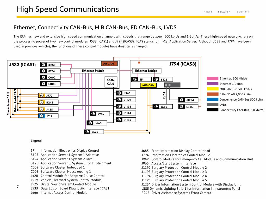
Ethernet, Connectivity CAN-Bus, MIB CAN-Bus, FD CAN-Bus, LVDS
The ID.4 has new and extensive high speed communication channels with speeds that range between 500 kbit/s and 1 Gbit/s. These high-speed networks rely on the processing power of two new control modules, J533 (iCAS1) and J794 (ICAS3). ICAS stands for In-Car Application Server. Although J533 and J794 have been used in previous vehicles, the functions of these control modules have drastically changed.
Legend
5F Information Electronics Display Control8123 Application Server 1 System 1 Adaptive8124 Application Server 1 System 2 Java8125 Application Server 3, System 1 for InfotainmentC002 Software Cluster, Imbedded 1C003 Software Cluster, Housekeeping 1J428 Control Module for Adaptive Cruise ControlJ519 Vehicle Electrical System Control ModuleJ525 Digital Sound System Control ModuleJ533 Data Bus on Board Diagnostic Interface (ICAS1)J666 Internet Access Control Module
J533 (ICAS1) J794 (ICAS3)Ethernet Bridge
5F 8125
8124
8123
C002
C003CON. CAN
Ethernet Switch
J666
J965
J1192
J1193
J1194
J1195
J949
MIB CAN
J525
J772
R242
J428
J519
J685
AB CAN
L385
J1254
LVD
S
Con
veni
ence
CA
N
Dri
ver
Ass
ist C
AN
J685 Front Information Display Control HeadJ794 Information Electronics Control Module 1J949 Control Module for Emergency Call Module and Communication UnitJ965 Access/Start System InterfaceJ1192 Burglary Protection Control Module 2J1193 Burglary Protection Control Module 3J1194 Burglary Protection Control Module 4J1195 Burglary Protection Control Module 5J1254 Driver Information System Control Module with Display UnitL385 Dynamic Lighting Strip 1 for Information in Instrument PanelR242 Driver Assistance Systems Front Camera
Ethernet, 100 Mbit/s
Ethernet 1 Gbit/s
MIB CAN-Bus 500 kbit/s
CAN-FD AB 2,000 kbit/s
Convenience CAN-Bus 500 kbit/s
LVDS
Connectivity CAN-Bus 500 kbit/s
8
High Speed Communications
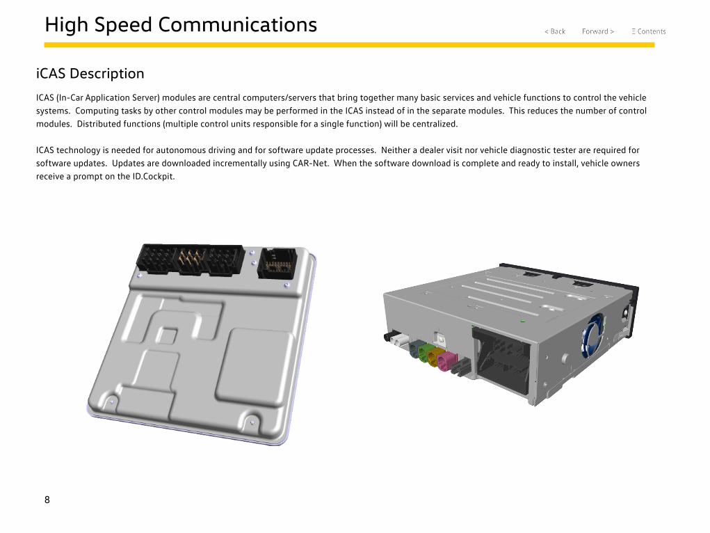
iCAS Description
ICAS (In-Car Application Server) modules are central computers/servers that bring together many basic services and vehicle functions to control the vehicle systems. Computing tasks by other control modules may be performed in the ICAS instead of in the separate modules. This reduces the number of control modules. Distributed functions (multiple control units responsible for a single function) will be centralized.
ICAS technology is needed for autonomous driving and for software update processes. Neither a dealer visit nor vehicle diagnostic tester are required for software updates. Updates are downloaded incrementally using CAR-Net. When the software download is complete and ready to install, vehicle owners receive a prompt on the ID.Cockpit.
9
High Speed Communications
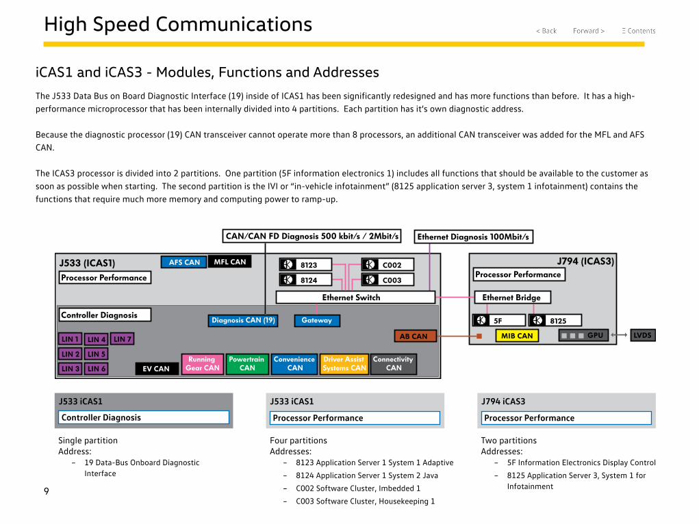
iCAS1 and iCAS3 - Modules, Functions and Addresses
The J533 Data Bus on Board Diagnostic Interface (19) inside of ICAS1 has been significantly redesigned and has more functions than before. It has a high-performance microprocessor that has been internally divided into 4 partitions. Each partition has it’s own diagnostic address.
Because the diagnostic processor (19) CAN transceiver cannot operate more than 8 processors, an additional CAN transceiver was added for the MFL and AFS CAN.
The ICAS3 processor is divided into 2 partitions. One partition (5F information electronics 1) includes all functions that should be available to the customer as soon as possible when starting. The second partition is the IVI or “in-vehicle infotainment” (8125 application server 3, system 1 infotainment) contains the functions that require much more memory and computing power to ramp-up.
J533 (ICAS1) J794 (ICAS3)
Ethernet Bridge
5F 8125
8124
8123 C002
Ethernet Switch
MIB CAN LVDSGPU
Processor Performance
Controller Diagnosis
C003
LIN 3
LIN 2
LIN 1
LIN 6
LIN 5
LIN 4 LIN 7
EV CANRunning
Gear CANPowertrain
CANConvenience
CANDriver Assist Systems CAN
Connectivity CAN
AFS CAN MFL CAN
GatewayDiagnosis CAN (19)
CAN/CAN FD Diagnosis 500 kbit/s / 2Mbit/s Ethernet Diagnosis 100Mbit/s
Processor Performance
AB CAN
J533 iCAS1 J533 iCAS1 J794 iCAS3
Controller Diagnosis Processor Performance Processor Performance
Single partitionAddress:
– 19 Data-Bus Onboard Diagnostic Interface
Four partitionsAddresses:
– 8123 Application Server 1 System 1 Adaptive
– 8124 Application Server 1 System 2 Java
– C002 Software Cluster, Imbedded 1
– C003 Software Cluster, Housekeeping 1
Two partitionsAddresses:
– 5F Information Electronics Display Control
– 8125 Application Server 3, System 1 for Infotainment
10
High Speed Communications
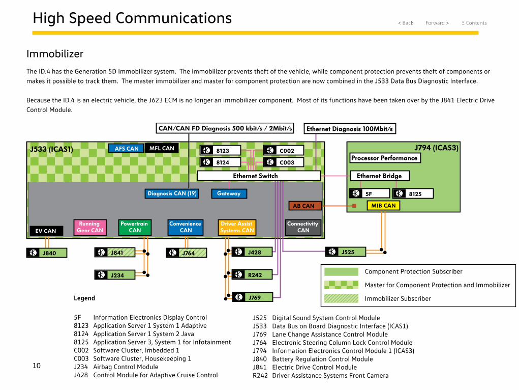
Immobilizer
The ID.4 has the Generation 5D Immobilizer system. The immobilizer prevents theft of the vehicle, while component protection prevents theft of components or makes it possible to track them. The master immobilizer and master for component protection are now combined in the J533 Data Bus Diagnostic Interface.
Because the ID.4 is an electric vehicle, the J623 ECM is no longer an immobilizer component. Most of its functions have been taken over by the J841 Electric Drive Control Module.
J533 (ICAS1) J794 (ICAS3)
Ethernet Bridge
5F 8125
8124
8123 C002
Ethernet Switch
C003
Running Gear CAN
Connectivity CAN
AFS CAN MFL CAN
GatewayDiagnosis CAN (19)
CAN/CAN FD Diagnosis 500 kbit/s / 2Mbit/s Ethernet Diagnosis 100Mbit/s
Processor Performance
AB CAN
J840
EV CAN
J764
Convenience CAN
Powertrain CAN
J841
J234
Driver Assist Systems CAN
J428
R242
J769
MIB CAN
J525
Legend
5F Information Electronics Display Control8123 Application Server 1 System 1 Adaptive8124 Application Server 1 System 2 Java8125 Application Server 3, System 1 for InfotainmentC002 Software Cluster, Imbedded 1C003 Software Cluster, Housekeeping 1J234 Airbag Control ModuleJ428 Control Module for Adaptive Cruise Control
J525 Digital Sound System Control ModuleJ533 Data Bus on Board Diagnostic Interface (ICAS1)J769 Lane Change Assistance Control ModuleJ764 Electronic Steering Column Lock Control ModuleJ794 Information Electronics Control Module 1 (ICAS3)J840 Battery Regulation Control ModuleJ841 Electric Drive Control ModuleR242 Driver Assistance Systems Front Camera
Component Protection Subscriber
Master for Component Protection and Immobilizer
Immobilizer Subscriber
11
Lighting
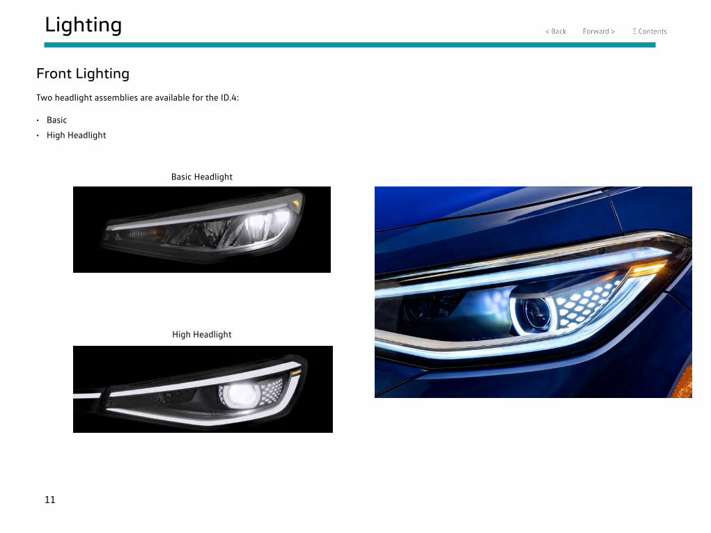
Front Lighting
Two headlight assemblies are available for the ID.4:
• Basic
• High Headlight
Basic Headlight
High Headlight
12
Lighting
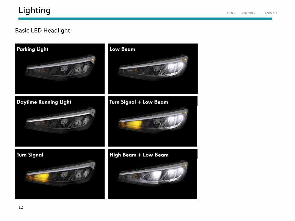
Basic LED Headlight
Turn Signal
Low BeamParking Light
Daytime Running Light Turn Signal + Low Beam
High Beam + Low Beam
13
Lighting
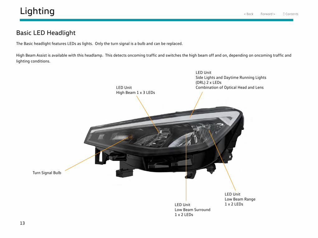
Basic LED Headlight
The Basic headlight features LEDs as lights. Only the turn signal is a bulb and can be replaced.
High Beam Assist is available with this headlamp. This detects oncoming traffic and switches the high beam off and on, depending on oncoming traffic and lighting conditions.
Turn Signal Bulb
LED Unit High Beam 1 x 3 LEDs
LED UnitSide Lights and Daytime Running Lights (DRL) 2 x LEDs Combination of Optical Head and Lens
LED UnitLow Beam Surround 1 x 2 LEDs
LED UnitLow Beam Range 1 x 2 LEDs
14
Lighting
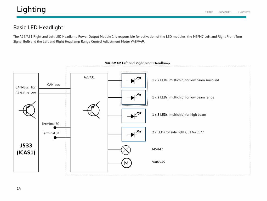
Basic LED Headlight
The A27/A31 Right and Left LED Headlamp Power Output Module 1 is responsible for activation of the LED modules, the M5/M7 Left and Right Front Turn Signal Bulb and the Left and Right Headlamp Range Control Adjustment Motor V48/V49.
CAN-Bus High
CAN-Bus Low
J533(ICAS1)
A27/31
M
1 x 2 LEDs (multichip) for low beam surround
1 x 2 LEDs (multichip) for low beam range
1 x 3 LEDs (multichip) for high beam
2 x LEDs for side lights, L176/L177
M5/M7
V48/V49
MX1/MX2 Left and Right Front Headlamp
Terminal 30
Terminal 31
CAN bus
15
Lighting
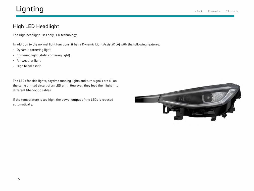
High LED Headlight
The High headlight uses only LED technology.
In addition to the normal light functions, it has a Dynamic Light Assist (DLA) with the following features:
• Dynamic cornering light
• Cornering light (static cornering light)
• All-weather light
• High beam assist
The LEDs for side lights, daytime running lights and turn signals are all on the same printed circuit of an LED unit. However, they feed their light into different fiber-optic cables.
If the temperature is too high, the power output of the LEDs is reduced automatically.
16
Lighting
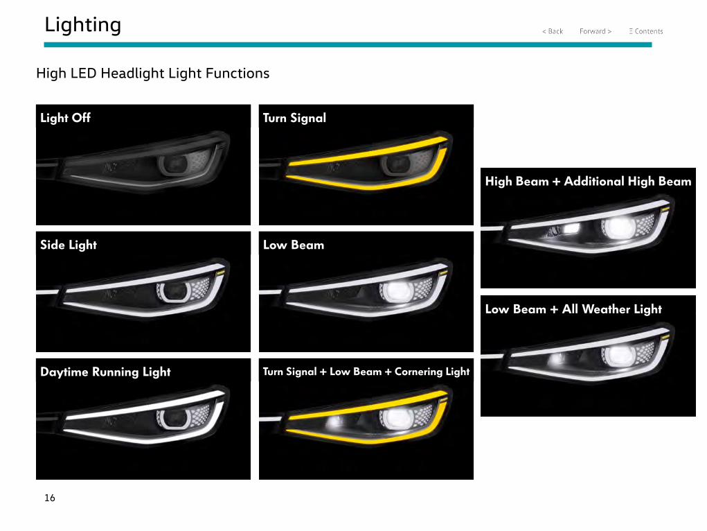
Light Off Turn Signal
Low BeamSide Light
Daytime Running Light Turn Signal + Low Beam + Cornering Light
High Beam + Additional High Beam
Low Beam + All Weather Light
High LED Headlight Light Functions

17
Lighting
High LED Headlight
LED UnitLow Beam (and Dynamic Cornering Light) 7 x LEDs and High Beam 11 x LEDs
LED UnitAdditional High Beam 3 x LEDs
LED UnitCornering Light1 x 3 LEDs
Turn Signal 5 x LEDs(in side/Daytime Running Light LED Unit)
Side Lights and Ambient Light 6 x and 8 x LEDs
LED UnitSide/Daytime Running Light (DRL)Upper and Lower Light Strip 2 x and 3 x LEDs with Fiber Optic Technology
18
Lighting
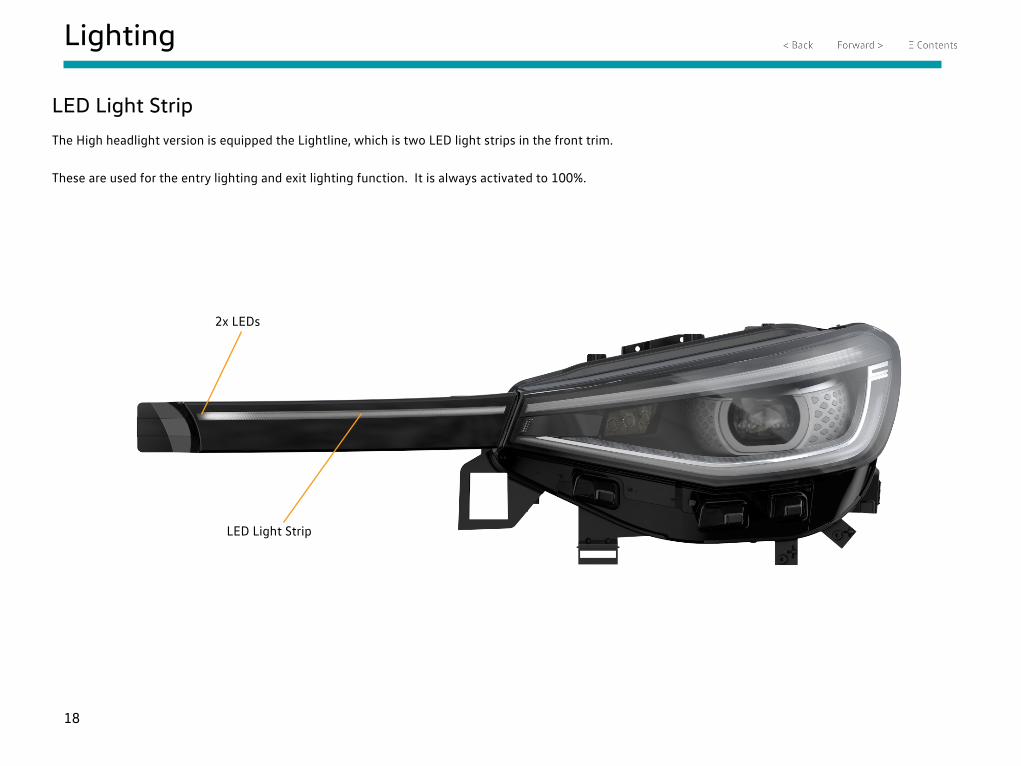
LED Light Strip
The High headlight version is equipped the Lightline, which is two LED light strips in the front trim.
These are used for the entry lighting and exit lighting function. It is always activated to 100%.
2x LEDs
LED Light Strip
19
Lighting
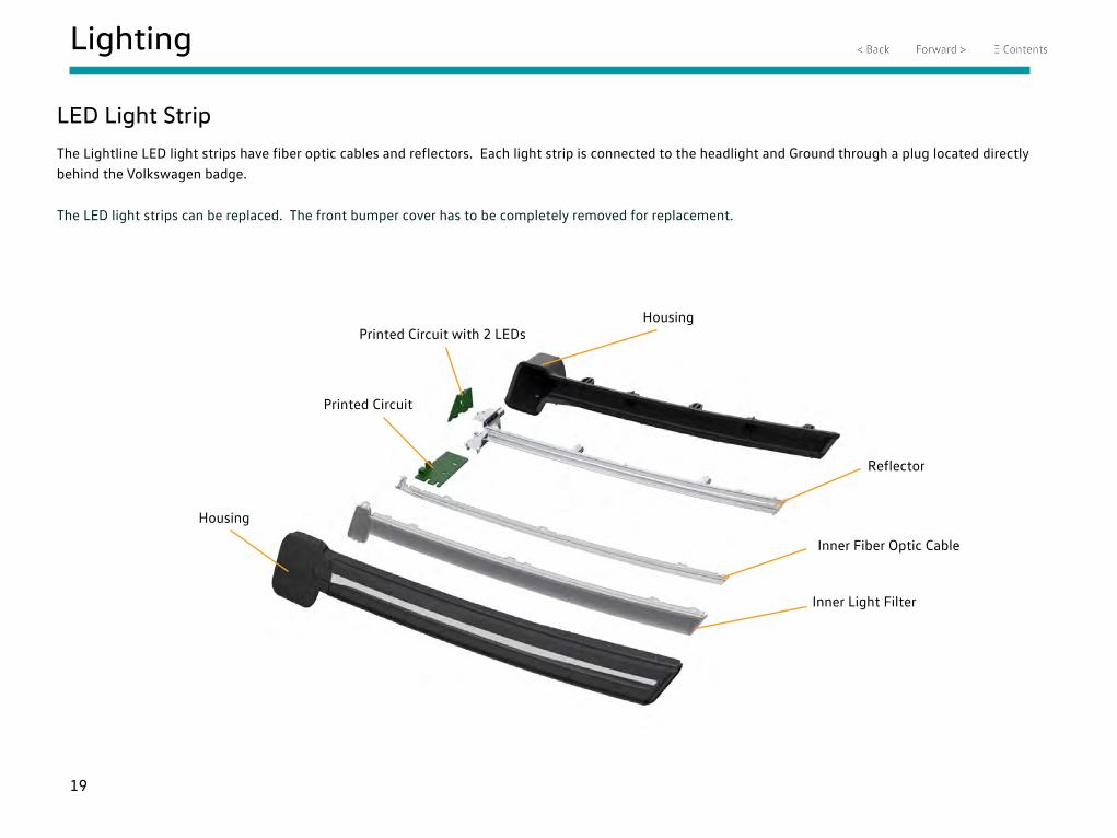
LED Light Strip
The Lightline LED light strips have fiber optic cables and reflectors. Each light strip is connected to the headlight and Ground through a plug located directly behind the Volkswagen badge.
The LED light strips can be replaced. The front bumper cover has to be completely removed for replacement.
Housing
Housing
Reflector
Inner Fiber Optic Cable
Inner Light Filter
Printed Circuit
Printed Circuit with 2 LEDs
20
Lighting
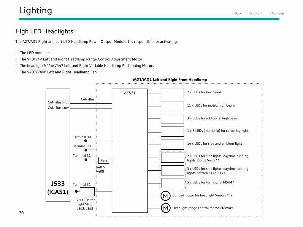
High LED Headlights
The A27/A31 Right and Left LED Headlamp Power Output Module 1 is responsible for activating:
• The LED modules
• The V48/V49 Left and Right Headlamp Range Control Adjustment Motor
• The headlight V446/V447 Left and Right Variable Headlamp Positioning Motors
• The V407/V408 Left and Right Headlamp Fan
CAN-Bus High
CAN-Bus Low
J533(ICAS1)
A27/31
M
MX1/MX2 Left and Right Front Headlamp
Terminal 30
Terminal 31
FanTerminal 31
M
CAN-Bus
V407/V408
2 x LEDs for Light Strip L362/L363
7 x LEDs for low beam
11 x LEDs for matrix high beam
3 x LEDs for additional high beam
1 x 3 LEDs (multichip) for cornering light
14 x LEDs for side and ambient light
2 x LEDs for side lights, daytime running lights top L176/L177
3 x LEDs for side lights, daytime running lights bottom L176/L177
5 x LEDs for turn signal M5/M7
Control motor for headlight V446/V447
Headlight range control motor V48/V49
Terminal 31
21
Lighting
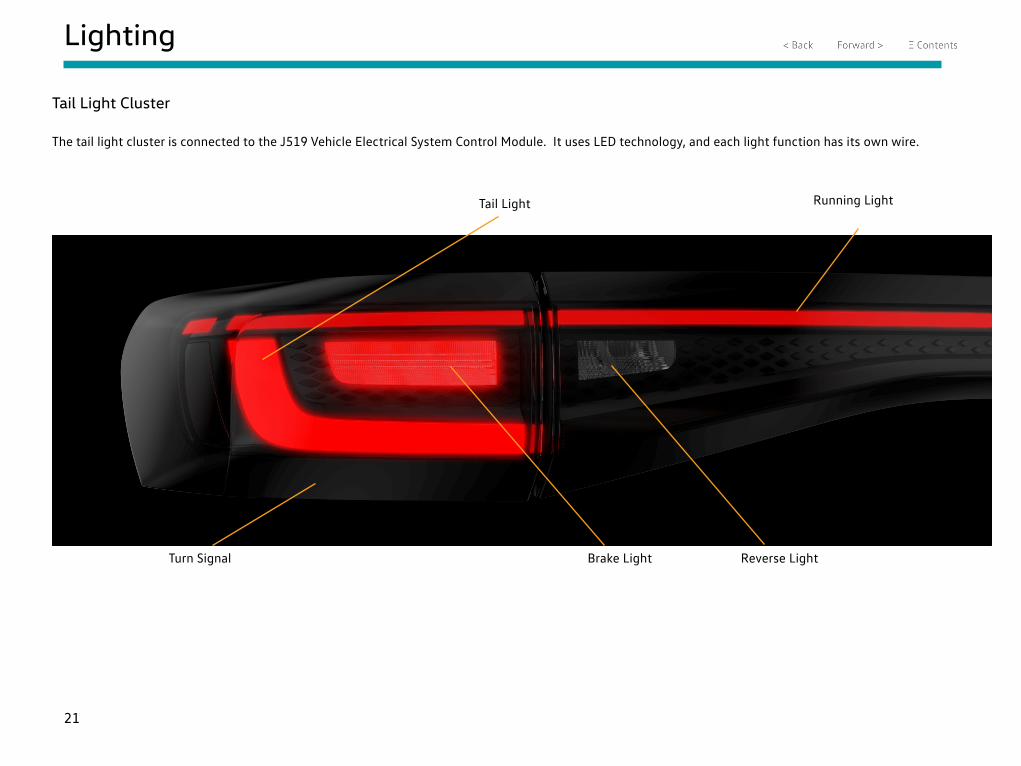
Tail Light Cluster
The tail light cluster is connected to the J519 Vehicle Electrical System Control Module. It uses LED technology, and each light function has its own wire.
Tail Light Running Light
Brake LightTurn Signal Reverse Light
22
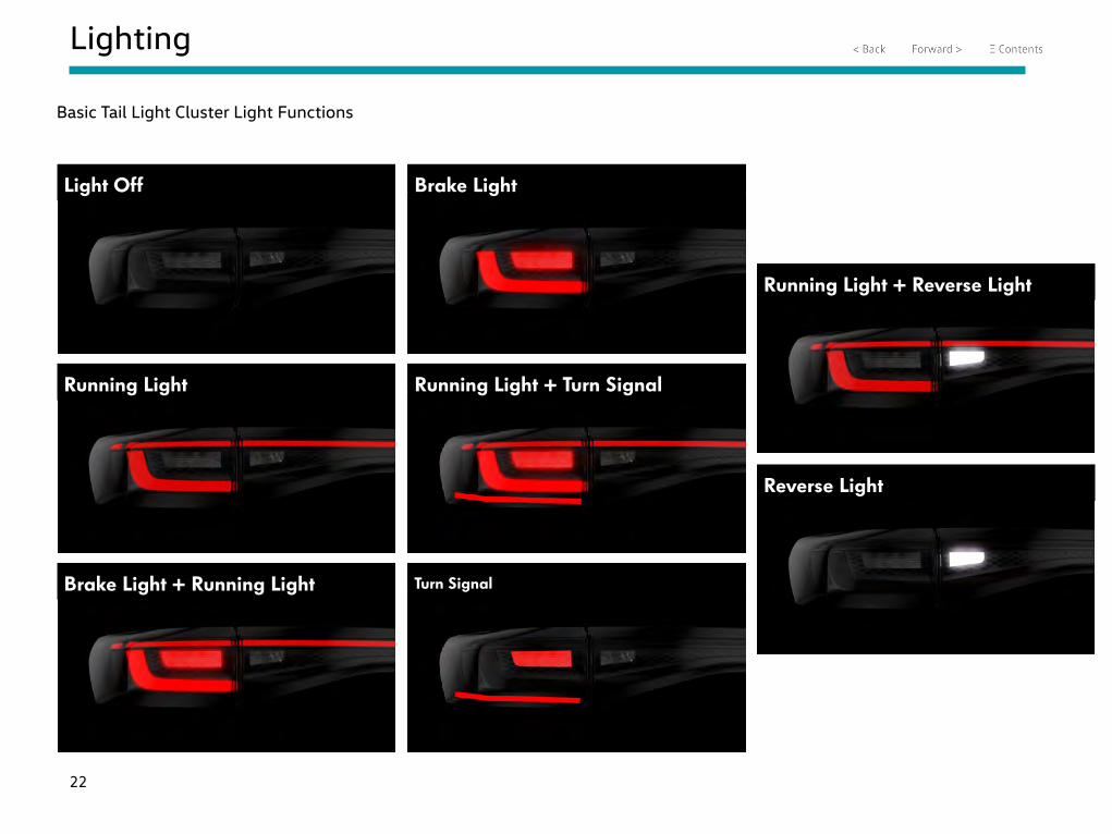
Lighting
Light Off Brake Light
Running Light + Turn SignalRunning Light
Brake Light + Running Light Turn Signal
Running Light + Reverse Light
Reverse Light
Basic Tail Light Cluster Light Functions
23
Lighting
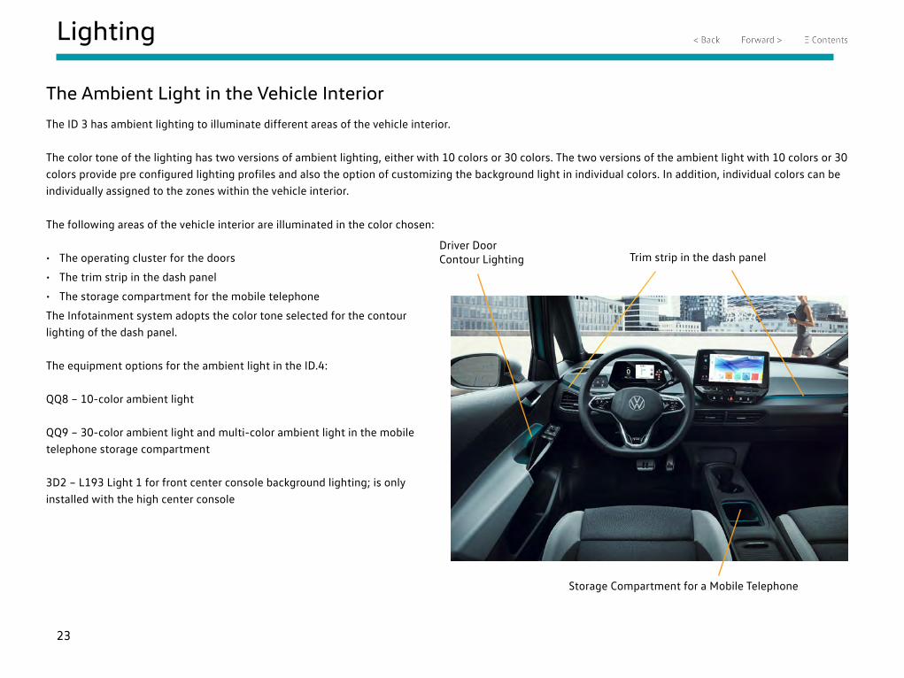
The Ambient Light in the Vehicle Interior
The ID 3 has ambient lighting to illuminate different areas of the vehicle interior.
The color tone of the lighting has two versions of ambient lighting, either with 10 colors or 30 colors. The two versions of the ambient light with 10 colors or 30 colors provide pre configured lighting profiles and also the option of customizing the background light in individual colors. In addition, individual colors can be individually assigned to the zones within the vehicle interior.
The following areas of the vehicle interior are illuminated in the color chosen:
• The operating cluster for the doors
• The trim strip in the dash panel
• The storage compartment for the mobile telephone
The Infotainment system adopts the color tone selected for the contour lighting of the dash panel.
The equipment options for the ambient light in the ID.4:
QQ8 – 10-color ambient light
QQ9 – 30-color ambient light and multi-color ambient light in the mobile telephone storage compartment
3D2 – L193 Light 1 for front center console background lighting; is only installed with the high center console
Trim strip in the dash panelDriver Door Contour Lighting
Storage Compartment for a Mobile Telephone
24
Lighting
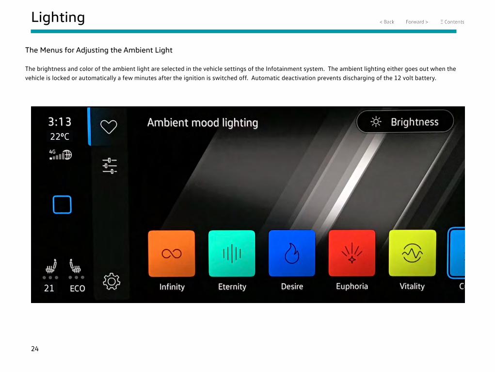
The Menus for Adjusting the Ambient Light
The brightness and color of the ambient light are selected in the vehicle settings of the Infotainment system. The ambient lighting either goes out when the vehicle is locked or automatically a few minutes after the ignition is switched off. Automatic deactivation prevents discharging of the 12 volt battery.
220C
21

25
Lighting
The Menus for Adjusting the Ambient Light
The three touch surfaces can be used to set the three zones at the top, center and bottom of the vehicle.
• Top: dash panel contour lighting
• Middle: door lighting
• Bottom: lighting of the storage compartment for the mobile telephone
The example of the three touch surfaces on the slide shows that
• The left touch surface generates a color in all three zones
• The middle touch surface generates a blue dash panel contour lighting and a green color for the door illumination and the mobile phone storage compartment
• The right-hand touch surface generates blue lighting for the dash panel contour and the mobile telephone storage compartment, and green lighting for the door illumination
Options for Adjusting the Color Distribution of the Ambient Light
Slider for Adjusting the Second Color Content of the Ambient Light
Slider for Adjusting the First Color Content of the Ambient Light
220C
21
26
Lighting
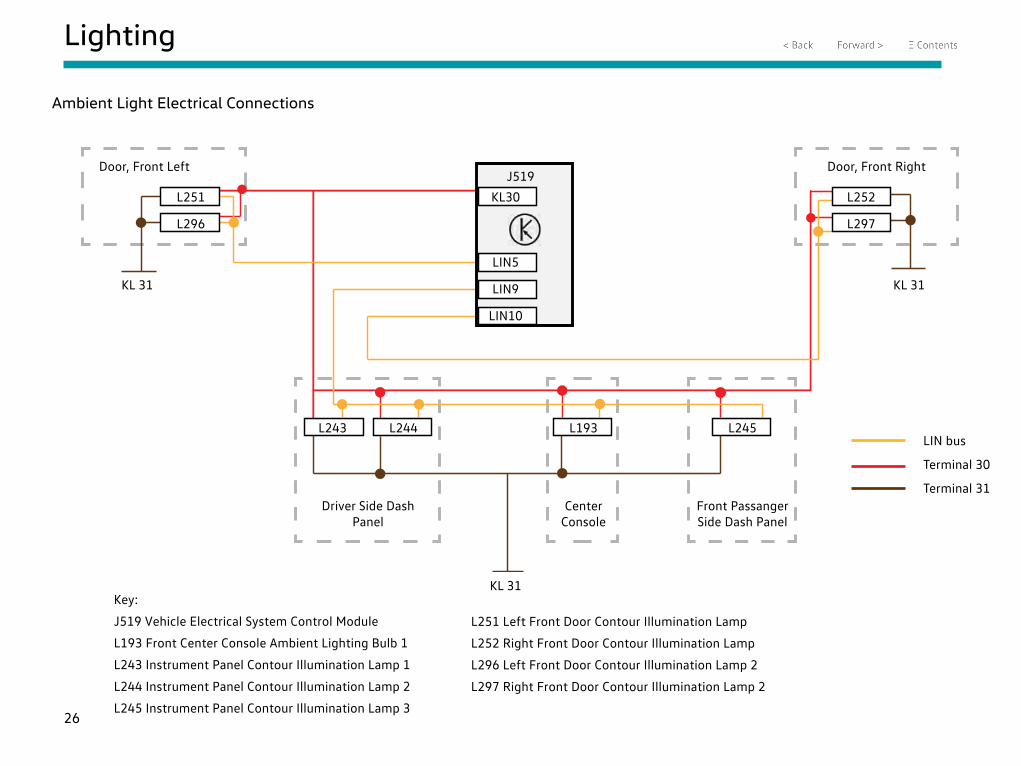
Ambient Light Electrical Connections
L251
L296
KL30
LIN5
LIN9
LIN10
L252
L297
L243 L244 L193 L245
J519
KL 31 KL 31
KL 31
Door, Front Left Door, Front Right
Driver Side Dash Panel
Center Console
Front Passanger Side Dash Panel
Terminal 30
LIN bus
Terminal 31
Key:
J519 Vehicle Electrical System Control Module
L193 Front Center Console Ambient Lighting Bulb 1
L243 Instrument Panel Contour Illumination Lamp 1
L244 Instrument Panel Contour Illumination Lamp 2
L245 Instrument Panel Contour Illumination Lamp 3
L251 Left Front Door Contour Illumination Lamp
L252 Right Front Door Contour Illumination Lamp
L296 Left Front Door Contour Illumination Lamp 2
L297 Right Front Door Contour Illumination Lamp 2
27
Lighting
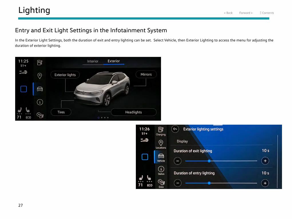
Entry and Exit Light Settings in the Infotainment System
In the Exterior Light Settings, both the duration of exit and entry lighting can be set. Select Vehicle, then Exterior Lighting to access the menu for adjusting the duration of exterior lighting.
28
Lighting
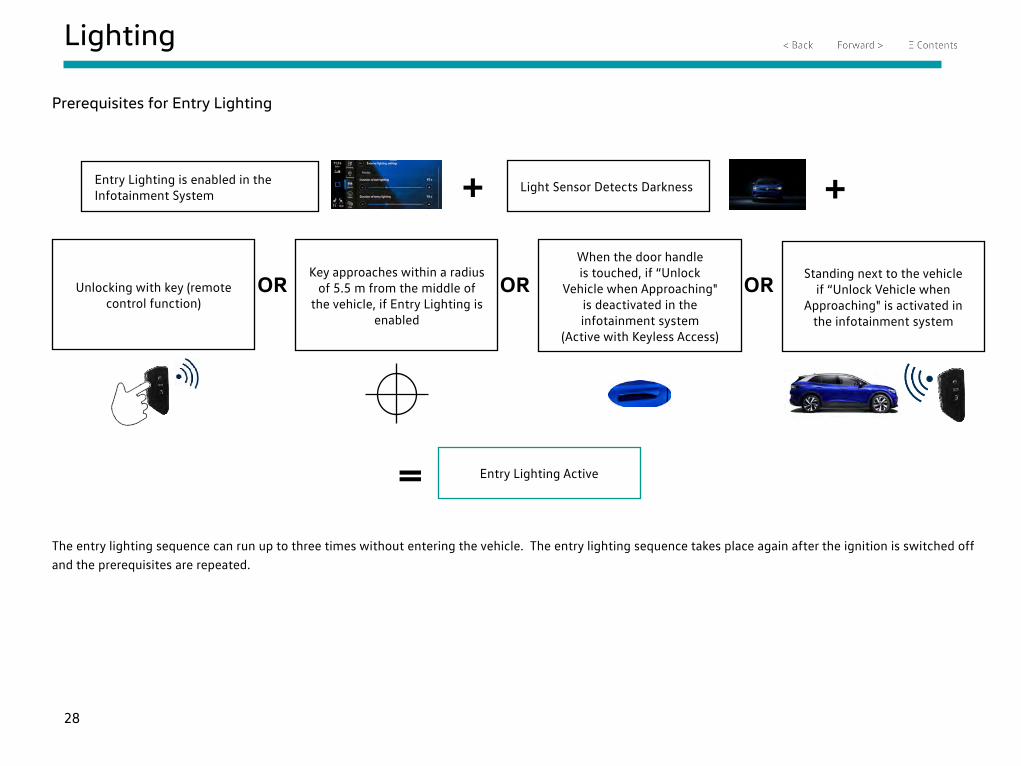
Prerequisites for Entry Lighting
Entry Lighting is enabled in the Infotainment System
Light Sensor Detects Darkness
Unlocking with key (remote control function)
+ +
Key approaches within a radius of 5.5 m from the middle of
the vehicle, if Entry Lighting is enabled
When the door handle is touched, if “Unlock
Vehicle when Approaching" is deactivated in the infotainment system
(Active with Keyless Access)
Standing next to the vehicle if “Unlock Vehicle when
Approaching" is activated in the infotainment system
OR OR OR
= Entry Lighting Active
The entry lighting sequence can run up to three times without entering the vehicle. The entry lighting sequence takes place again after the ignition is switched off and the prerequisites are repeated.
29
Lighting
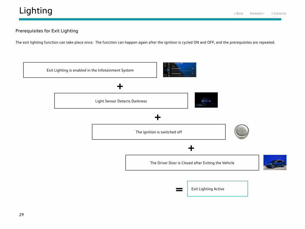
Exit Lighting is enabled in the Infotainment System
Light Sensor Detects Darkness
+
Prerequisites for Exit Lighting
The exit lighting function can take place once. The function can happen again after the ignition is cycled ON and OFF, and the prerequisites are repeated.
The ignition is switched off
+
The Driver Door is Closed after Exiting the Vehicle
+
= Exit Lighting Active
30
Energy Management
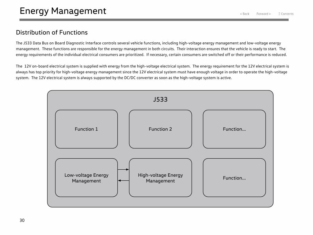
Distribution of Functions
The J533 Data Bus on Board Diagnostic Interface controls several vehicle functions, including high-voltage energy management and low-voltage energy management. These functions are responsible for the energy management in both circuits. Their interaction ensures that the vehicle is ready to start. The energy requirements of the individual electrical consumers are prioritized. If necessary, certain consumers are switched off or their performance is reduced.
The 12V on-board electrical system is supplied with energy from the high-voltage electrical system. The energy requirement for the 12V electrical system is always has top priority for high-voltage energy management since the 12V electrical system must have enough voltage in order to operate the high-voltage system. The 12V electrical system is always supported by the DC/DC converter as soon as the high-voltage system is active.
J533
Function 1
Low-voltage Energy Management
Function 2
High-voltage Energy Management
Function...
Function...
31
Energy Management
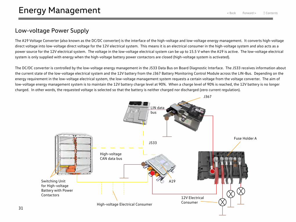
Low-voltage Power Supply
The A19 Voltage Converter (also known as the DC/DC converter) is the interface of the high-voltage and low-voltage energy management. It converts high-voltage direct voltage into low-voltage direct voltage for the 12V electrical system. This means it is an electrical consumer in the high-voltage system and also acts as a power source for the 12V electrical system. The voltage in the low-voltage electrical system can be up to 15.5 V when the A19 is active. The low-voltage electrical system is only supplied with energy when the high-voltage battery power contactors are closed (high-voltage system is activated).
The DC/DC converter is controlled by the low-voltage energy management in the J533 Data Bus on Board Diagnostic Interface. The J533 receives information about the current state of the low-voltage electrical system and the 12V battery from the J367 Battery Monitoring Control Module across the LIN-Bus. Depending on the energy requirement in the low-voltage electrical system, the low-voltage management system requests a certain voltage from the voltage converter. The aim of low-voltage energy management system is to maintain the 12V battery charge level at 90%. When a charge level of 90% is reached, the 12V battery is no longer charged. In other words, the requested voltage is selected so that the battery is neither charged nor discharged (zero current regulation).
J533
High-voltage CAN data bus
LIN data bus
J367
Fuse Holder A
A19Switching Unit for High-voltage Battery with Power Contactors
High-voltage Electrical Consumer
12V Electrical Consumer
32
Energy Management
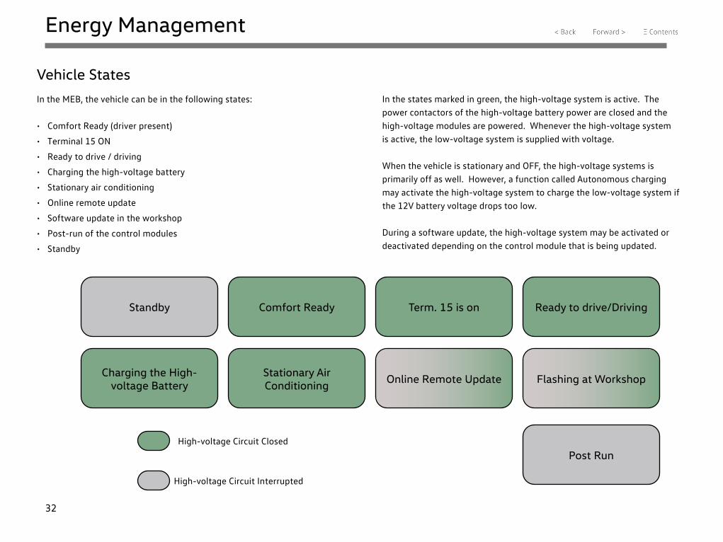
Vehicle States
In the MEB, the vehicle can be in the following states:
• Comfort Ready (driver present)
• Terminal 15 ON
• Ready to drive / driving
• Charging the high-voltage battery
• Stationary air conditioning
• Online remote update
• Software update in the workshop
• Post-run of the control modules
• Standby
In the states marked in green, the high-voltage system is active. The power contactors of the high-voltage battery power are closed and the high-voltage modules are powered. Whenever the high-voltage system is active, the low-voltage system is supplied with voltage.
When the vehicle is stationary and OFF, the high-voltage systems is primarily off as well. However, a function called Autonomous charging may activate the high-voltage system to charge the low-voltage system if the 12V battery voltage drops too low.
During a software update, the high-voltage system may be activated or deactivated depending on the control module that is being updated.
Standby Comfort Ready Term. 15 is on Ready to drive/Driving
Flashing at WorkshopOnline Remote UpdateStationary Air Conditioning
Charging the High-voltage Battery
High-voltage Circuit Closed
High-voltage Circuit Interrupted
Post Run
33
Energy Management
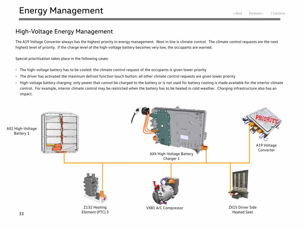
High-Voltage Energy Management
The A19 Voltage Converter always has the highest priority in energy management. Next in line is climate control. The climate control requests are the next highest level of priority. If the charge level of the high-voltage battery becomes very low, the occupants are warned.
Special prioritization takes place in the following cases:
• The high-voltage battery has to be cooled: the climate control request of the occupants is given lower priority
• The driver has activated the maximum defrost function touch button: all other climate control requests are given lower priority
• High-voltage battery charging: only power that cannot be charged to the battery or is not used for battery cooling is made available for the interior climate control. For example, interior climate control may be restricted when the battery has to be heated in cold weather. Charging infrastructure also has an impact.
AX2 High-Voltage Battery 1
AX4 High-Voltage Battery Charger 1
A19 Voltage Converter
Z132 Heating Element (PTC) 3
VX81 A/C Compressor ZX15 Driver Side Heated Seat
34
Terminal Control
Starting the Vehicle
Vehicle Unlocked / Driver Seat Not Occupied
Comfort Ready: PARK
Ignition off, air conditioning active infotainment active
++
Ignition switched on PARK
+ +
Ready to drive READY
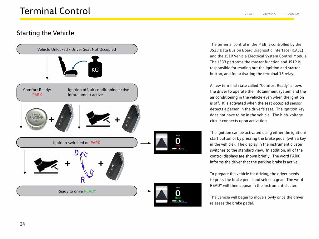
The terminal control in the MEB is controlled by the J533 Data Bus on Board Diagnostic Interface (ICAS1) and the J519 Vehicle Electrical System Control Module. The J533 performs the master function and J519 is responsible for reading out the ignition and starter button, and for activating the terminal 15 relay.
A new terminal state called “Comfort Ready” allows the driver to operate the infotainment system and the air conditioning in the vehicle even when the ignition is off. It is activated when the seat occupied sensor detects a person in the driver’s seat. The ignition key does not have to be in the vehicle. The high-voltage circuit connects upon activation.
The ignition can be activated using either the ignition/start button or by pressing the brake pedal (with a key in the vehicle). The display in the instrument cluster switches to the standard view. In addition, all of the control displays are shown briefly. The word PARK informs the driver that the parking brake is active.
To prepare the vehicle for driving, the driver needs to press the brake pedal and select a gear. The word READY will then appear in the instrument cluster.
The vehicle will begin to move slowly once the driver releases the brake pedal.
35
Terminal Control
MEB Exiting Concept
Vehicle Stationary / Door Closed / Ready to drive READY
+ ++
Ignition Switched on PARK
Comfort Ready: PARK
Ignition off, air conditioning active infotainment active
+
+
+
+
+
+ + 30 min
Vehicle Deactivated
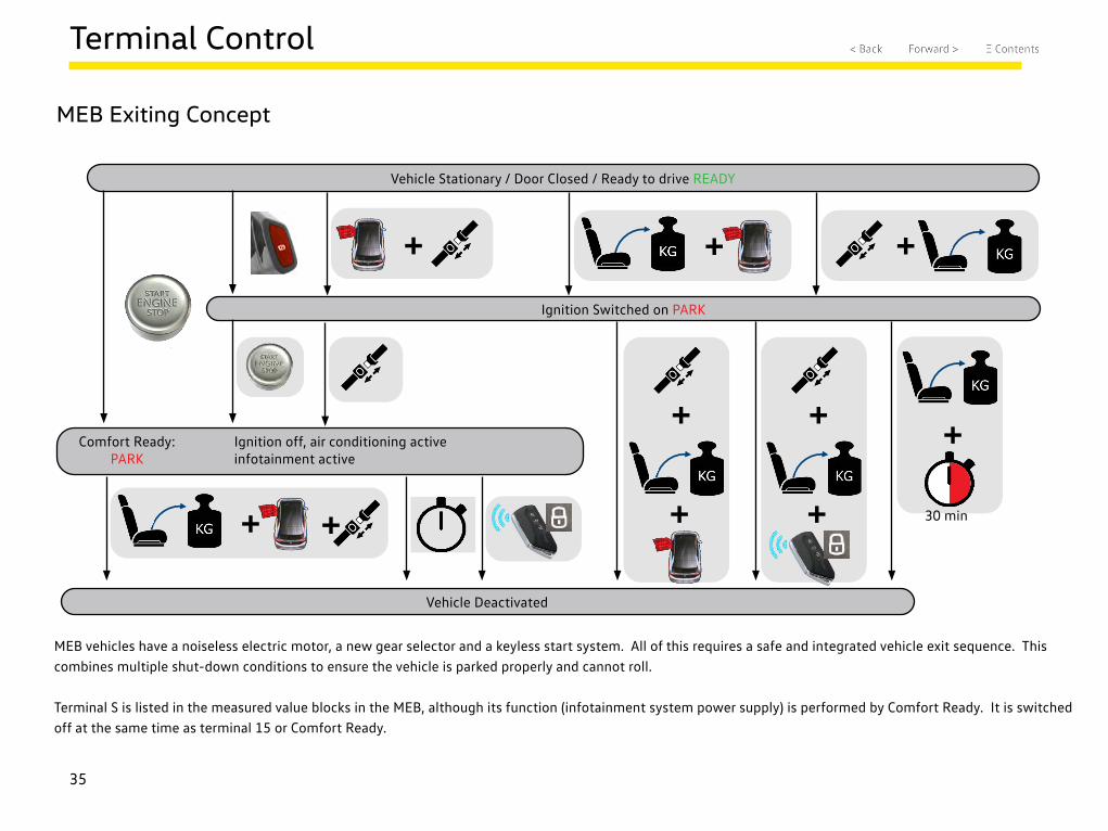
MEB vehicles have a noiseless electric motor, a new gear selector and a keyless start system. All of this requires a safe and integrated vehicle exit sequence. This combines multiple shut-down conditions to ensure the vehicle is parked properly and cannot roll.
Terminal S is listed in the measured value blocks in the MEB, although its function (infotainment system power supply) is performed by Comfort Ready. It is switched off at the same time as terminal 15 or Comfort Ready.
36
Terminal Control
MEB Exiting Concept - Turning off the Vehicle Drive System
Vehicle Stationary / Door Closed / Ready to drive READY
+ ++
Ignition Switched on PARK
Comfort Ready: PARK
Ignition off, air conditioning active infotainment active
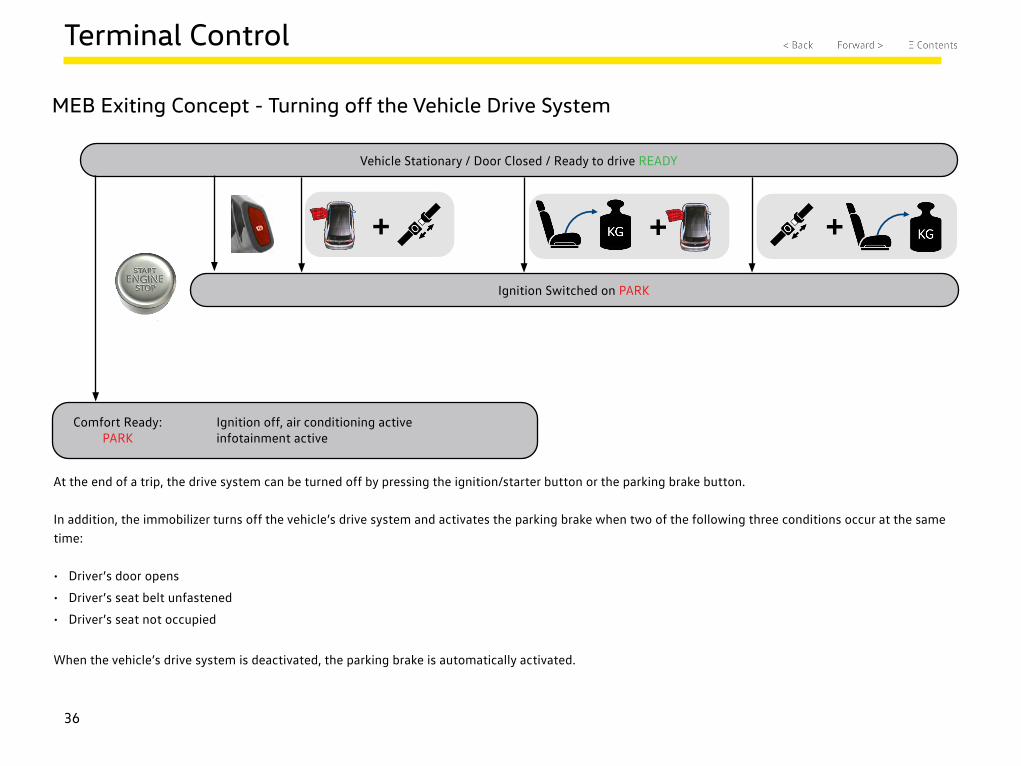
At the end of a trip, the drive system can be turned off by pressing the ignition/starter button or the parking brake button.
In addition, the immobilizer turns off the vehicle’s drive system and activates the parking brake when two of the following three conditions occur at the same time:
• Driver’s door opens
• Driver’s seat belt unfastened
• Driver’s seat not occupied
When the vehicle’s drive system is deactivated, the parking brake is automatically activated.
37
Terminal Control
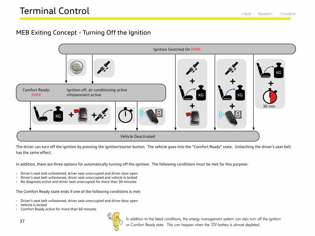
MEB Exiting Concept - Turning Off the Ignition
Ignition Switched On PARK
Comfort Ready: PARK
Ignition off, air conditioning active infotainment active
+
+
+
+
+
+ +30 min
Vehicle Deactivated
The driver can turn off the ignition by pressing the ignition/starter button. The vehicle goes into the “Comfort Ready” state. Unlatching the driver’s seat belt has the same effect.
In addition, there are three options for automatically turning off the ignition. The following conditions must be met for this purpose:
• Driver’s seat belt unfastened, driver seat unoccupied and driver door open• Driver’s seat belt unfastened, driver seat unoccupied and vehicle is locked• No diagnosis active and driver seat unoccupied for more than 30 minutes
The Comfort Ready state ends if one of the following conditions is met:
• Driver’s seat belt unfastened, driver seat unoccupied and driver door open• Vehicle is locked• Comfort Ready active for more than 60 minutes
In addition to the listed conditions, the energy management system can also turn off the ignition or Comfort Ready state. This can happen when the 12V battery is almost depleted.
38
Terminal Control
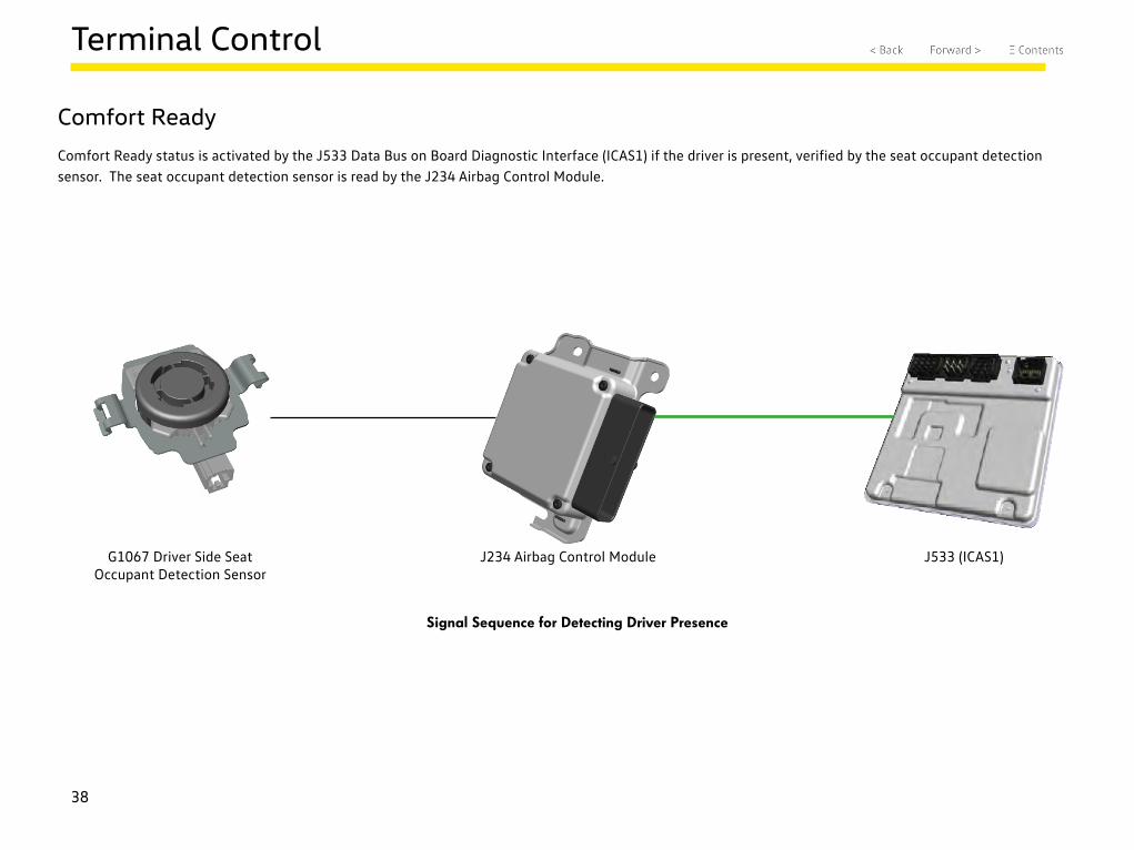
Comfort Ready
Comfort Ready status is activated by the J533 Data Bus on Board Diagnostic Interface (ICAS1) if the driver is present, verified by the seat occupant detection sensor. The seat occupant detection sensor is read by the J234 Airbag Control Module.
G1067 Driver Side Seat Occupant Detection Sensor
J234 Airbag Control Module J533 (ICAS1)
Signal Sequence for Detecting Driver Presence
39
Terminal Control
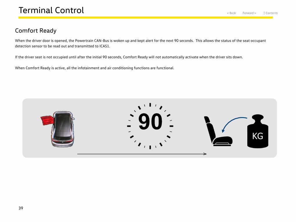
Comfort Ready
When the driver door is opened, the Powertrain CAN-Bus is woken up and kept alert for the next 90 seconds. This allows the status of the seat occupant detection sensor to be read out and transmitted to ICAS1.
If the driver seat is not occupied until after the initial 90 seconds, Comfort Ready will not automatically activate when the driver sits down.
When Comfort Ready is active, all the infotainment and air conditioning functions are functional.
40
Terminal Control
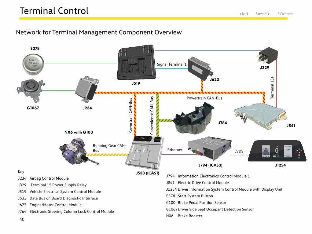
Network for Terminal Management Component Overview
J519
E378
G1067 J234
NX6 with G100
J533 (ICAS1)
J794 (ICAS3) J1254
J764J841
J623
J329
Term
inal
15a
Ethernet
Signal Terminal 1
Powertrain CAN-Bus
Pow
ertr
ain
CAN
-Bus
Conv
enie
nce
CAN
-Bus
Running Gear CAN-Bus LVDS
Key
J234 Airbag Control Module
J329 Terminal 15 Power Supply Relay
J519 Vehicle Electrical System Control Module
J533 Data Bus on Board Diagnostic Interface
J623 Engine/Motor Control Module
J764 Electronic Steering Column Lock Control Module
J794 Information Electronics Control Module 1
J841 Electric Drive Control Module
J1254 Driver Information System Control Module with Display Unit
E378 Start System Button
G100 Brake Pedal Position Sensor
G1067 Driver Side Seat Occupant Detection Sensor
NX6 Brake Booster
41
Terminal Control
J533 (ICAS1)
EthernetLVDS
G1067 J234
Powertrain CAN-Bus High-voltage Battery CAN-Bus
VX21
J386
J979 J840
Convenience CAN-Bus
J794 (ICAS3) J685
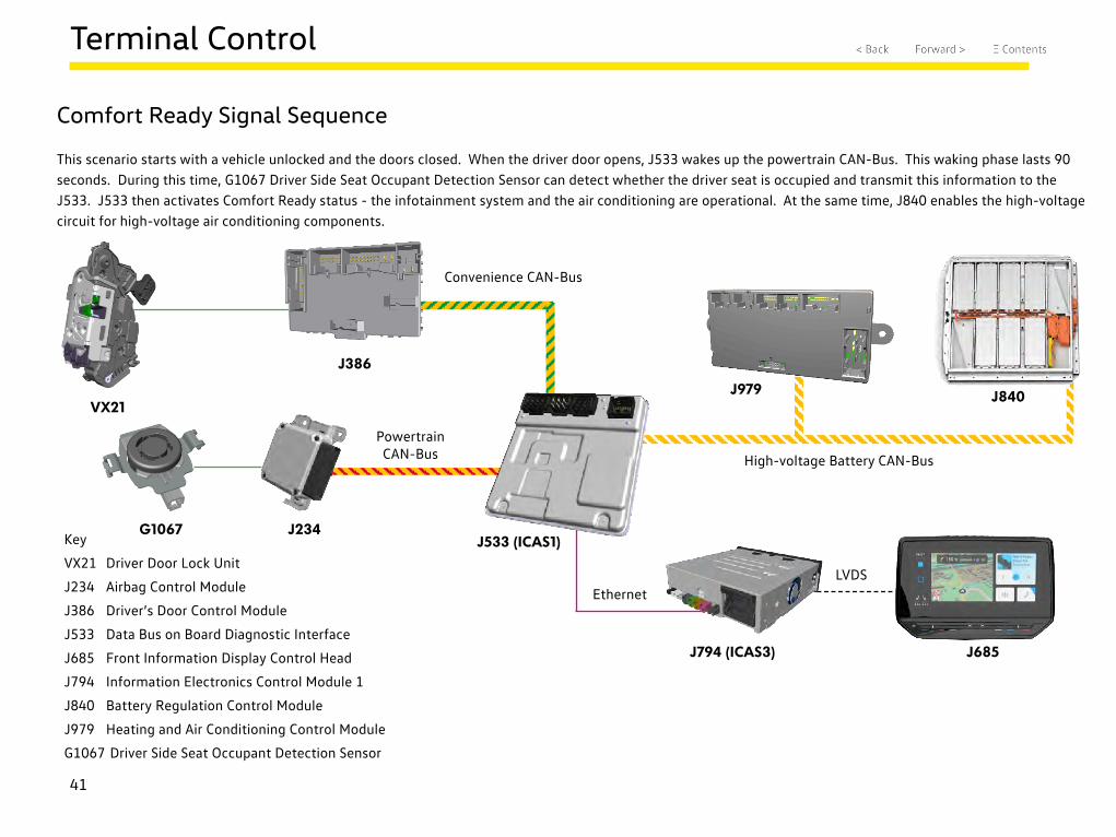
Comfort Ready Signal Sequence
This scenario starts with a vehicle unlocked and the doors closed. When the driver door opens, J533 wakes up the powertrain CAN-Bus. This waking phase lasts 90 seconds. During this time, G1067 Driver Side Seat Occupant Detection Sensor can detect whether the driver seat is occupied and transmit this information to the J533. J533 then activates Comfort Ready status - the infotainment system and the air conditioning are operational. At the same time, J840 enables the high-voltage circuit for high-voltage air conditioning components.
Key
VX21 Driver Door Lock Unit
J234 Airbag Control Module
J386 Driver’s Door Control Module
J533 Data Bus on Board Diagnostic Interface
J685 Front Information Display Control Head
J794 Information Electronics Control Module 1
J840 Battery Regulation Control Module
J979 Heating and Air Conditioning Control Module
G1067 Driver Side Seat Occupant Detection Sensor
42
Terminal Control
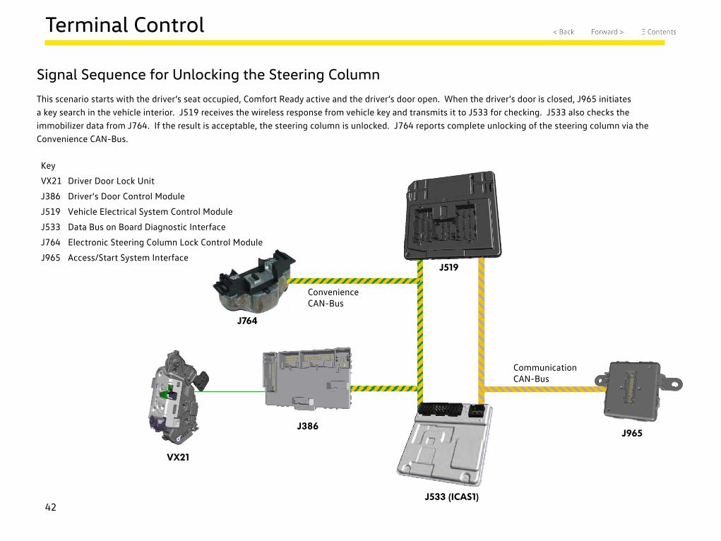
Signal Sequence for Unlocking the Steering Column
This scenario starts with the driver’s seat occupied, Comfort Ready active and the driver’s door open. When the driver’s door is closed, J965 initiates a key search in the vehicle interior. J519 receives the wireless response from vehicle key and transmits it to J533 for checking. J533 also checks the immobilizer data from J764. If the result is acceptable, the steering column is unlocked. J764 reports complete unlocking of the steering column via the Convenience CAN-Bus.
Key
VX21 Driver Door Lock Unit
J386 Driver’s Door Control Module
J519 Vehicle Electrical System Control Module
J533 Data Bus on Board Diagnostic Interface
J764 Electronic Steering Column Lock Control Module
J965 Access/Start System Interface
VX21
J386
J519
J533 (ICAS1)
J764
Communication CAN-Bus
Convenience CAN-Bus
J965
43
Terminal Control
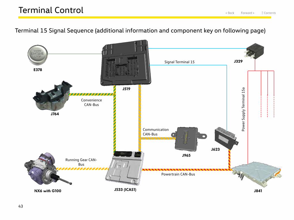
Terminal 15 Signal Sequence (additional information and component key on following page)
J519
J533 (ICAS1)
J764
Communication CAN-Bus
Convenience CAN-Bus
E378
J329
J841NX6 with G100
Running Gear CAN-Bus
J623
Pow
er S
uppl
y Te
rmin
al 1
5a
Signal Terminal 15
J965
Powertrain CAN-Bus
44
Terminal Control
Terminal 15 Signal Sequence (this information correlates to the previous page)
This scenario starts with the driver’s seat occupied, driver’s door closed and the steering column unlocked. J533 receives the driver’s request to activate the ignition either by brake pedal actuation (through Running Gear CAN-Bus) or by pressing the ignition and starter button (through the Convenience CAN -Bus). J965 initiates a key search in the vehicle interior. J519 receives the wireless response from the vehicle key and transmits it to J533 for checking. If the result is acceptable, J533 sends the message “Terminal 15 active” on all data buses. J519 also sends a discrete terminal 15 signal to the J623 and activates the J329 relay to the voltage supply of terminal 15. The potential switched by J329 supplies several components in the vehicle, including the J841 to provide vehicle movement.
Key
J329 Terminal 15 Power Supply Relay
J519 Vehicle Electrical System Control Module
J533 Data Bus on Board Diagnostic Interface
J623 Engine/Motor Control Module
J764 Electronic Steering Column Lock Control Module
J841 Electric Drive Control Module
J965 Access/Start System Interface
E378 Start System Button
G100 Brake Pedal Position Sensor
NX6 Brake Booster
45
Terminal Control
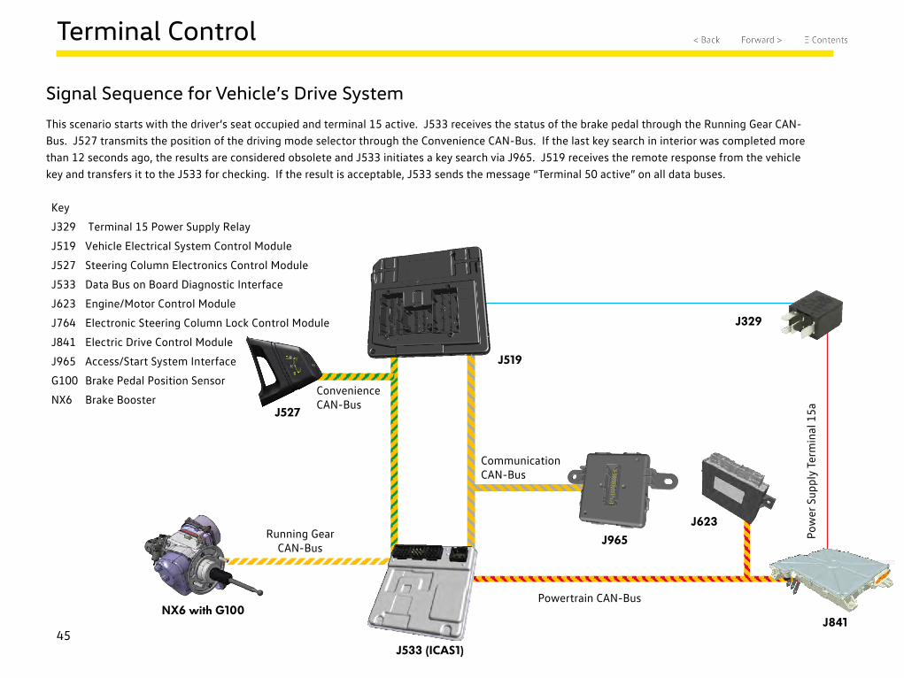
Signal Sequence for Vehicle’s Drive System
This scenario starts with the driver’s seat occupied and terminal 15 active. J533 receives the status of the brake pedal through the Running Gear CAN-Bus. J527 transmits the position of the driving mode selector through the Convenience CAN-Bus. If the last key search in interior was completed more than 12 seconds ago, the results are considered obsolete and J533 initiates a key search via J965. J519 receives the remote response from the vehicle key and transfers it to the J533 for checking. If the result is acceptable, J533 sends the message “Terminal 50 active” on all data buses.
Key
J329 Terminal 15 Power Supply Relay
J519 Vehicle Electrical System Control Module
J527 Steering Column Electronics Control Module
J533 Data Bus on Board Diagnostic Interface
J623 Engine/Motor Control Module
J764 Electronic Steering Column Lock Control Module
J841 Electric Drive Control Module
J965 Access/Start System Interface
G100 Brake Pedal Position Sensor
NX6 Brake Booster
J519
J533 (ICAS1)
J527
Communication CAN-Bus
Convenience CAN-Bus
J329
J841NX6 with G100
Running Gear CAN-Bus
J623
Pow
er S
uppl
y Te
rmin
al 1
5a
J965
Powertrain CAN-Bus
46
Keyless Entry and Access (KESSY)
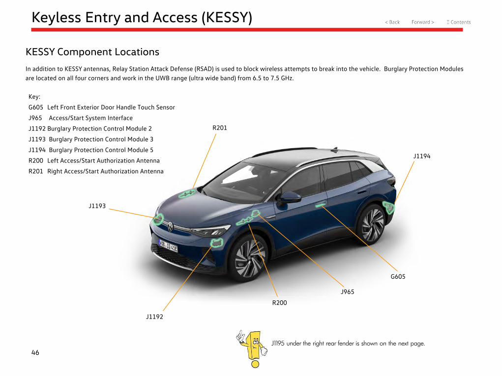
KESSY Component Locations
In addition to KESSY antennas, Relay Station Attack Defense (RSAD) is used to block wireless attempts to break into the vehicle. Burglary Protection Modules are located on all four corners and work in the UWB range (ultra wide band) from 6.5 to 7.5 GHz.
Key:
G605 Left Front Exterior Door Handle Touch Sensor
J965 Access/Start System Interface
J1192 Burglary Protection Control Module 2
J1193 Burglary Protection Control Module 3
J1194 Burglary Protection Control Module 5
R200 Left Access/Start Authorization Antenna
R201 Right Access/Start Authorization Antenna
R201
J1194
G605
J965
R200
J1192
J1193
J1195 under the right rear fender is shown on the next page.
47
Keyless Entry and Access (KESSY)
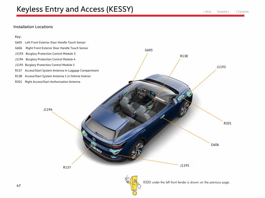
Installation Locations
Key:
G605 Left Front Exterior Door Handle Touch Sensor
G606 Right Front Exterior Door Handle Touch Sensor
J1193 Burglary Protection Control Module 3
J1194 Burglary Protection Control Module 4
J1195 Burglary Protection Control Module 5
R137 Access/Start System Antenna in Luggage Compartment
R138 Access/Start System Antenna 1 in Vehicle Interior
R201 Right Access/Start Authorization Antenna
G605
J1193
G606
J1195
R201
R137
J1194
R200 under the left front fender is shown on the previous page.
R138
48
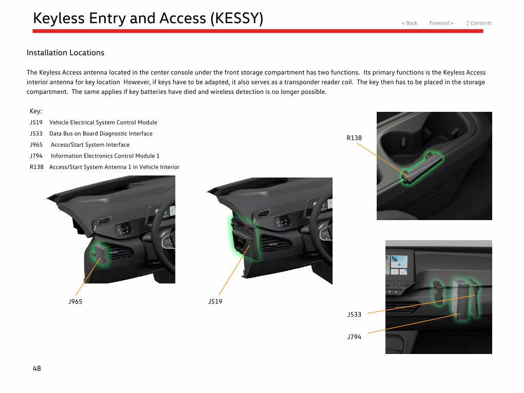
Keyless Entry and Access (KESSY)
Installation Locations
The Keyless Access antenna located in the center console under the front storage compartment has two functions. Its primary functions is the Keyless Access interior antenna for key location However, if keys have to be adapted, it also serves as a transponder reader coil. The key then has to be placed in the storage compartment. The same applies if key batteries have died and wireless detection is no longer possible.
Key:
J519 Vehicle Electrical System Control Module
J533 Data Bus on Board Diagnostic Interface
J965 Access/Start System Interface
J794 Information Electronics Control Module 1
R138 Access/Start System Antenna 1 in Vehicle Interior
J533
J794
R138
J519J965
49
Keyless Entry and Access (KESSY)
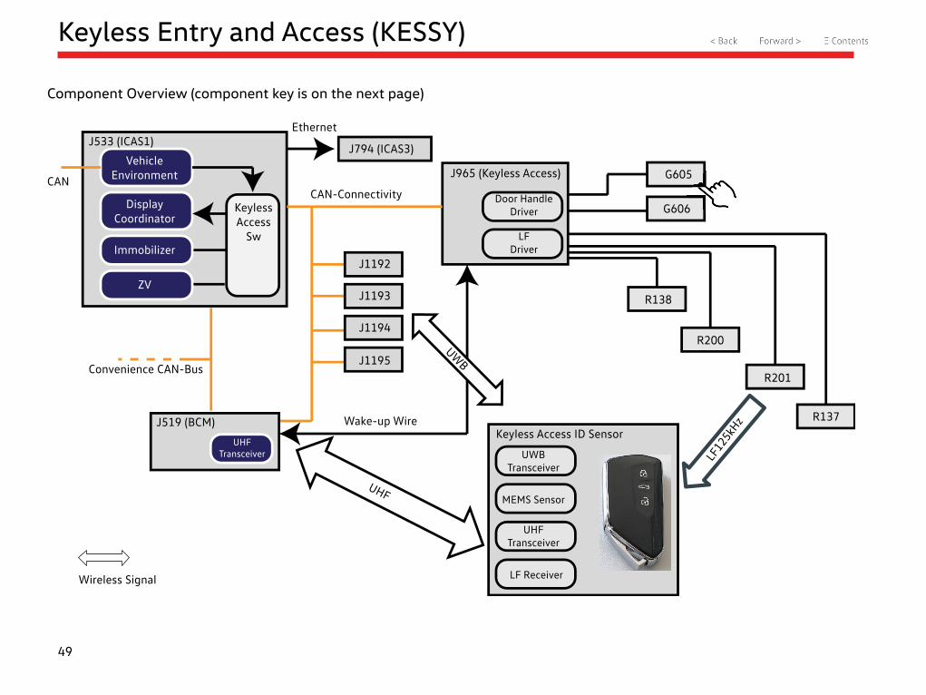
Component Overview (component key is on the next page)
Vehicle Environment
Display Coordinator
Immobilizer
ZV
CAN
J533 (ICAS1)
Keyless Access
Sw
Ethernet
J794 (ICAS3)
J1192
J1193
J1194
J1195
CAN-Connectivity
Convenience CAN-Bus
UHF Transceiver
J519 (BCM)
UHF
UWB
J965 (Keyless Access)
Door Handle Driver
LF Driver
G605
G606
R138
R200
R201
R137
LF12
5kHzWake-up Wire
Keyless Access ID Sensor
UWB Transceiver
MEMS Sensor
UHF Transceiver
LF ReceiverWireless Signal
50
Keyless Entry and Access (KESSY)
Component Overview (this information correlates to the previous page)
G605 Left Front Exterior Door Handle Touch Sensor
G606 Right Front Exterior Door Handle Touch Sensor
J519 Vehicle Electrical System Control Module
J533 Data Bus on Board Diagnostic Interface
J965 Access/Start System Interface
J794 Information Electronics Control Module 1
J1192 Burglary Protection Control Module 2
J1193 Burglary Protection Control Module 3
J1194 Burglary Protection Control Module 4
J1195 Burglary Protection Control Module 5
R137 Access/Start System Antenna in Luggage Compartment
R138 Access/Start System Antenna 1 in Vehicle Interior
R200 Left Access/Start Authorization Antenna
R201 Right Access/Start Authorization Antenna
UWB Ultra wide band. Frequency range used by VW 6.5 to 7.5 GHz
UHF 433/315 Hz frequency range (ultra high frequency)
MEMS sensor Micro electromechanical systems. Movement sensor in the key (internal transceiver is switched off after applied time and lack of motion)
Normally, the Low Frequency (LF) communication always goes from the LF aerials to the key. For emergency reading (key battery drained) or key modification in the workshop, the front Keyless Access aerial (R138) is used as a transponder reader coil and communication is bidirectional.
51
Keyless Entry and Access (KESSY)
Functional Overview (component key and communication information is on the next page)
Vehicle Environment
Display Coordinator
Immobilizer
ZV
CAN
J533 (ICAS1)
Keyless Access
Sw
Ethernet
J794 (ICAS3)
J1192
J1193
J1194
J1195
CAN-Connectivity
Convenience CAN-Bus
UHF Transceiver
J519 (BCM)
UHF
UWB
J965 (Keyless Access)
Door Handle Driver
LF Driver
G605
G606
R138
R200
R201
R137
LF12
5kHzWake-up Wire
Keyless Access ID Sensor
UWB Transceiver
MEMS Sensor
UHF Transceiver
LF ReceiverWireless Signal
1C
2F
2C
2D
2G
2A
1B2E
2B
1A
52
Keyless Entry and Access (KESSY)
Functional Overview (this information correlates to the previous page)
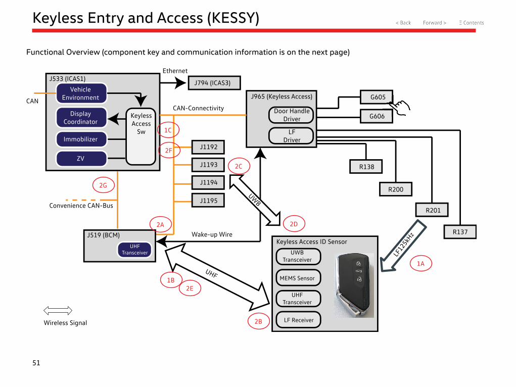
Communication sequence for vehicle access:
1A J965 Access/Start System Interface monitors the access/start system antennas to detect a key within range, such as contact with one of the two capacitive door handle sensors. The key identification is sent via the LF aerials (125 kHz, low frequency). At the same time, the J519 Vehicle Electrical System Control Module is woken up through a discrete line.
1B Response 1 of the key (ID sender) is sent to the J519 by UHF (315 MHz North American Region)
1C Because the J519 only has the UHF transceiver but is not the master for access approval, it sends the signals as CAN messages via CAN-Connectivity to the access master, ICAS1.
2A Request from ICAS1 to the J519 to signal the key to send additional identification data, including the information to be requested of the RSAD control units (J1192-J1195) through CAN.
2B The J519 forwards the request to the ID sender/key (UHF).
2C Request by the key RSAD control modules for identification and individual location data (UWB).
2D Response of the RSAD control modules to the key with identification and individual location data (UWB). The RSAD control modules also transmit this data redundantly to ICAS1.
2E Response 2 by the key sent to the J519 with all identification and individual location data location data (UHF)
2F The J519 transmits the signals via CAN messages on CAN-Connectivity to the access master, ICAS1. The data is then verified by ICAS1 (including the reference data of the RSAD control modules through CAN). The data and signal times are verified through CAN in real time by ICAS1, including the reference data for the Burglary Protection Control Modules. Key responses must occur in the time it would take if the key were physically located in the action areas of the vehicle.
2G If the calculation in ICAS1 is successful, the unlock command is sent via Convenience-CAN to the front door control module, as well as to the J519 for deactivating the closing modules of the rear doors.
All display data is controlled via Ethernet connection from the ICAS1 to the ICAS3 to visualize the Keyless Access information and settings on the center display and the dash panel insert.
53
Infotainment
Overview
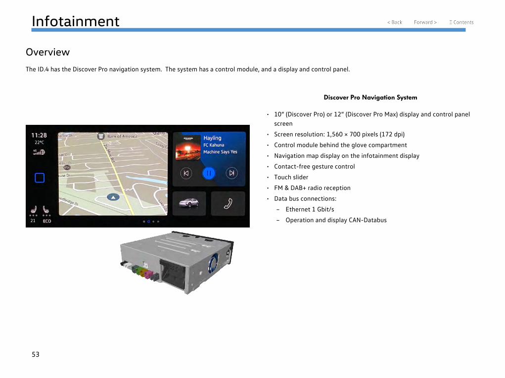
The ID.4 has the Discover Pro navigation system. The system has a control module, and a display and control panel.
• 10” (Discover Pro) or 12” (Discover Pro Max) display and control panel screen
• Screen resolution: 1,560 × 700 pixels (172 dpi)
• Control module behind the glove compartment
• Navigation map display on the infotainment display
• Contact-free gesture control
• Touch slider
• FM & DAB+ radio reception
• Data bus connections:
– Ethernet 1 Gbit/s
– Operation and display CAN-Databus
Discover Pro Navigation System
220C
21
54
Infotainment
J794 Information Electronics Control Module 1 (ICAS3)
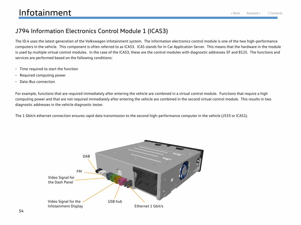
The ID.4 uses the latest generation of the Volkswagen infotainment system. The information electronics control module is one of the two high-performance computers in the vehicle. This component is often referred to as ICAS3. ICAS stands for In Car Application Server. This means that the hardware in the module is used by multiple virtual control modules. In the case of the ICAS3, these are the control modules with diagnostic addresses 5F and 8125. The functions and services are performed based on the following conditions:
• Time required to start the function
• Required computing power
• Data-Bus connection
For example, functions that are required immediately after entering the vehicle are combined in a virtual control module. Functions that require a high computing power and that are not required immediately after entering the vehicle are combined in the second virtual control module. This results in two diagnostic addresses in the vehicle diagnostic tester.
The 1 Gbit/s ethernet connection ensures rapid data transmission to the second high-performance computer in the vehicle (J533 or ICAS1).
DAB
FM
Video Signal for the Dash Panel
Video Signal for the Infotainment Display
USB hubEthernet 1 Gbit/s
55
Infotainment
J794 Information Electronics Control Module 1 (ICAS3)
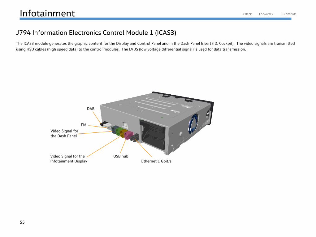
The ICAS3 module generates the graphic content for the Display and Control Panel and in the Dash Panel Insert (ID. Cockpit). The video signals are transmitted using HSD cables (high speed data) to the control modules. The LVDS (low voltage differential signal) is used for data transmission.
DAB
FMVideo Signal for the Dash Panel
Video Signal for the Infotainment Display
USB hubEthernet 1 Gbit/s
56
Infotainment
Network
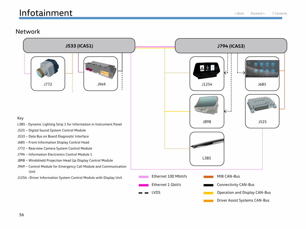
J533 (ICAS1) J794 (ICAS3)
Key
L385 - Dynamic Lighting Strip 1 for Information in Instrument Panel
J525 – Digital Sound System Control Module
J533 – Data Bus on Board Diagnostic Interface
J685 – Front Information Display Control Head
J772 – Rearview Camera System Control Module
J794 – Information Electronics Control Module 1
J898 – Windshield Projection Head Up Display Control Module
J949 – Control Module for Emergency Call Module and Communication Unit
J1254 –Driver Information System Control Module with Display Unit Ethernet 100 Mbit//s
Ethernet 1 Gbit/s
LVDS
MIB CAN-Bus
Connectivity CAN-Bus
Operation and Display CAN-Bus
Driver Assist Systems CAN-Bus
J772 J949 J1254
J898
L385
J685
J525
57
Infotainment
Scope of Function
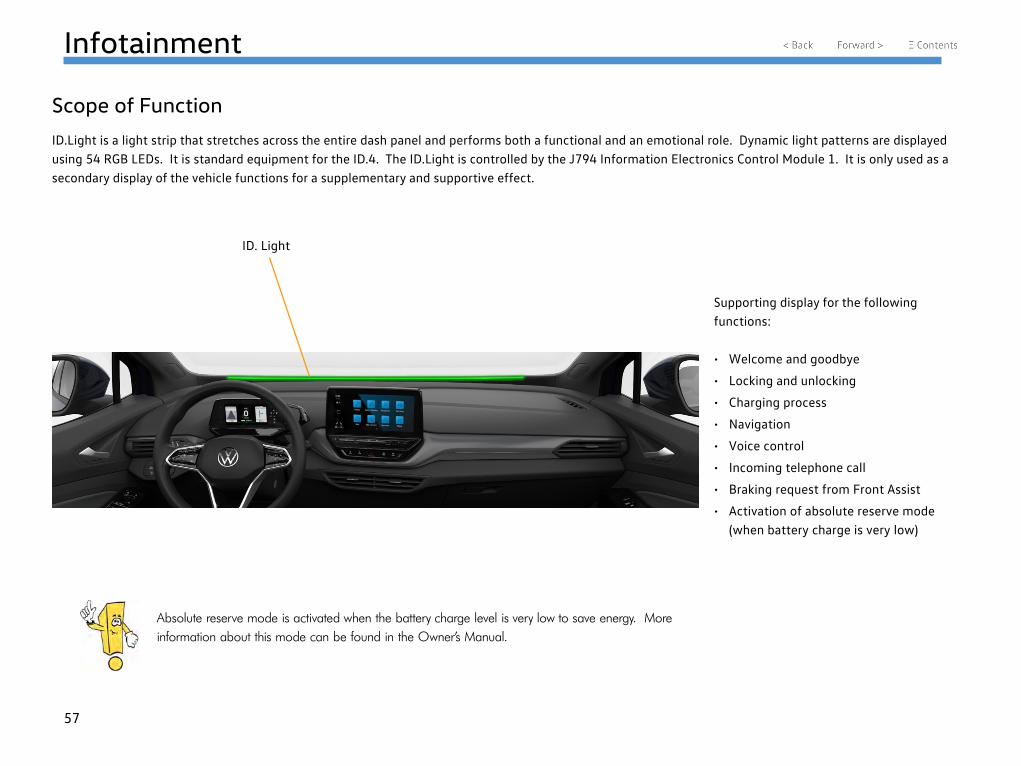
ID.Light is a light strip that stretches across the entire dash panel and performs both a functional and an emotional role. Dynamic light patterns are displayed using 54 RGB LEDs. It is standard equipment for the ID.4. The ID.Light is controlled by the J794 Information Electronics Control Module 1. It is only used as a secondary display of the vehicle functions for a supplementary and supportive effect.
Supporting display for the following functions:
• Welcome and goodbye
• Locking and unlocking
• Charging process
• Navigation
• Voice control
• Incoming telephone call
• Braking request from Front Assist
• Activation of absolute reserve mode (when battery charge is very low)
Absolute reserve mode is activated when the battery charge level is very low to save energy. More information about this mode can be found in the Owner’s Manual.
ID. Light
58
Infotainment
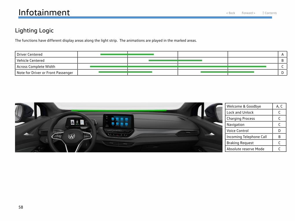
Lighting Logic
The functions have different display areas along the light strip. The animations are played in the marked areas.
Driver Centered A
Vehicle Centered B
Across Complete Width C
Note for Driver or Front Passenger D
Welcome & Goodbye A, C
Lock and Unlock C
Charging Process C
Navigation C
Voice Control D
Incoming Telephone Call B
Braking Request C
Absolute reserve Mode C
59
Infotainment
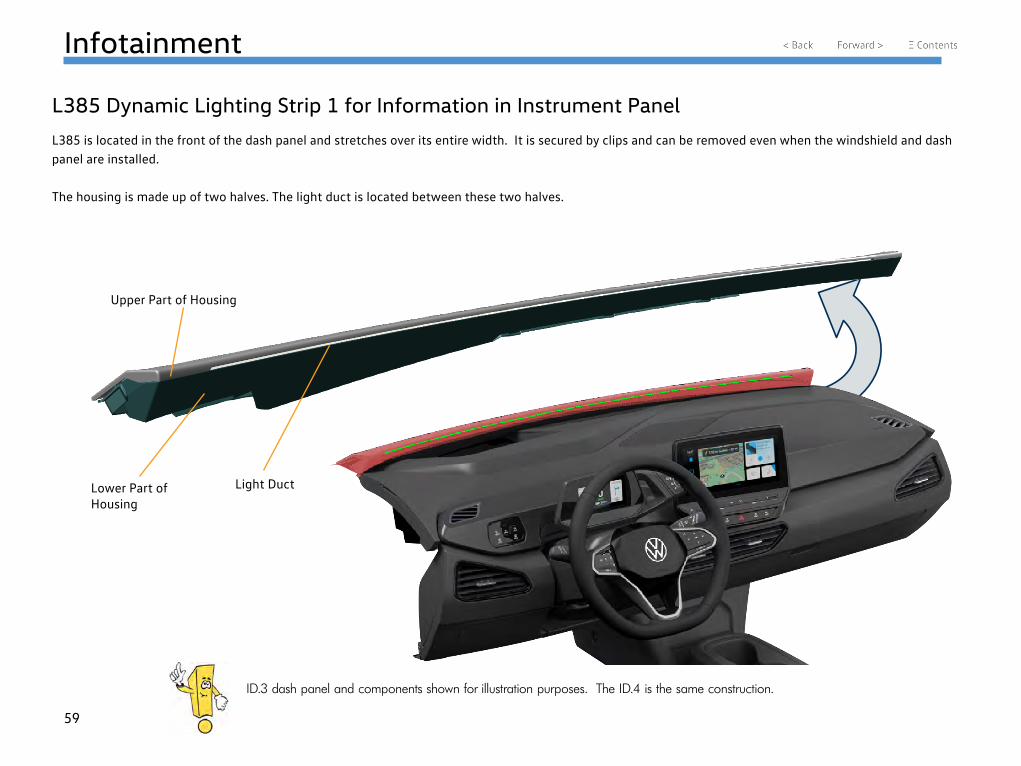
L385 Dynamic Lighting Strip 1 for Information in Instrument Panel
L385 is located in the front of the dash panel and stretches over its entire width. It is secured by clips and can be removed even when the windshield and dash panel are installed.
The housing is made up of two halves. The light duct is located between these two halves.
Upper Part of Housing
Lower Part of Housing
Light Duct
ID.3 dash panel and components shown for illustration purposes. The ID.4 is the same construction.
60
Infotainment
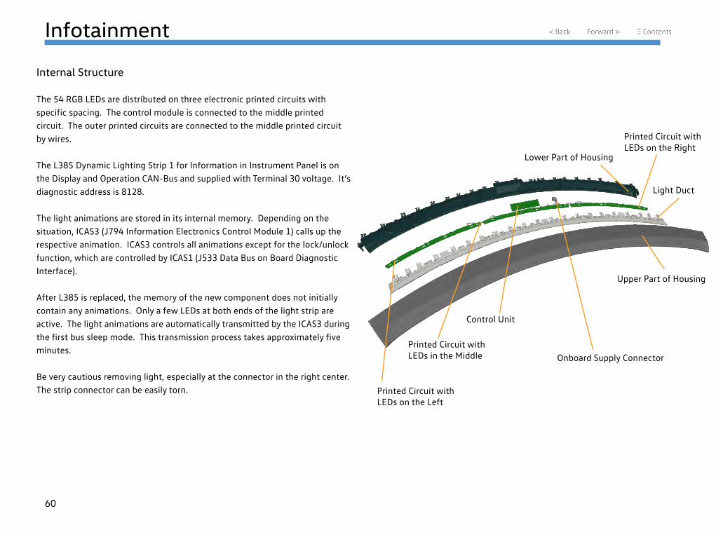
Internal Structure
The 54 RGB LEDs are distributed on three electronic printed circuits with specific spacing. The control module is connected to the middle printed circuit. The outer printed circuits are connected to the middle printed circuit by wires.
The L385 Dynamic Lighting Strip 1 for Information in Instrument Panel is on the Display and Operation CAN-Bus and supplied with Terminal 30 voltage. It’s diagnostic address is 8128.
The light animations are stored in its internal memory. Depending on the situation, ICAS3 (J794 Information Electronics Control Module 1) calls up the respective animation. ICAS3 controls all animations except for the lock/unlock function, which are controlled by ICAS1 (J533 Data Bus on Board Diagnostic Interface).
After L385 is replaced, the memory of the new component does not initially contain any animations. Only a few LEDs at both ends of the light strip are active. The light animations are automatically transmitted by the ICAS3 during the first bus sleep mode. This transmission process takes approximately five minutes.
Be very cautious removing light, especially at the connector in the right center. The strip connector can be easily torn. Printed Circuit with
LEDs on the Left
Printed Circuit with LEDs in the Middle
Control Unit
Lower Part of Housing
Printed Circuit with LEDs on the Right
Light Duct
Upper Part of Housing
Onboard Supply Connector
61
Infotainment
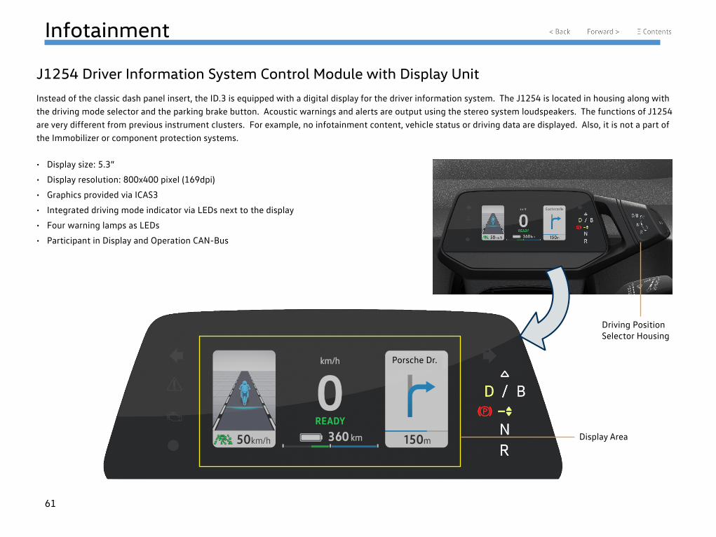
J1254 Driver Information System Control Module with Display Unit
Instead of the classic dash panel insert, the ID.3 is equipped with a digital display for the driver information system. The J1254 is located in housing along with the driving mode selector and the parking brake button. Acoustic warnings and alerts are output using the stereo system loudspeakers. The functions of J1254 are very different from previous instrument clusters. For example, no infotainment content, vehicle status or driving data are displayed. Also, it is not a part of the Immobilizer or component protection systems.
• Display size: 5.3”
• Display resolution: 800x400 pixel (169dpi)
• Graphics provided via ICAS3
• Integrated driving mode indicator via LEDs next to the display
• Four warning lamps as LEDs
• Participant in Display and Operation CAN-Bus
Porsche Dr.
Driving Position Selector Housing
Display Area
62
Infotainment
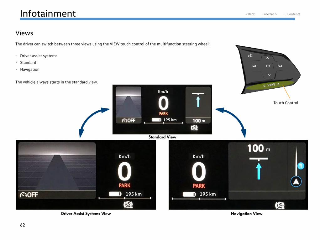
Views
The driver can switch between three views using the VIEW touch control of the multifunction steering wheel:
• Driver assist systems
• Standard
• Navigation
The vehicle always starts in the standard view.
Standard View
Driver Assist Systems View Navigation View
Touch Control
Km/h
195 km
195 km 195 km
Km/h Km/hm
m
63
Infotainment
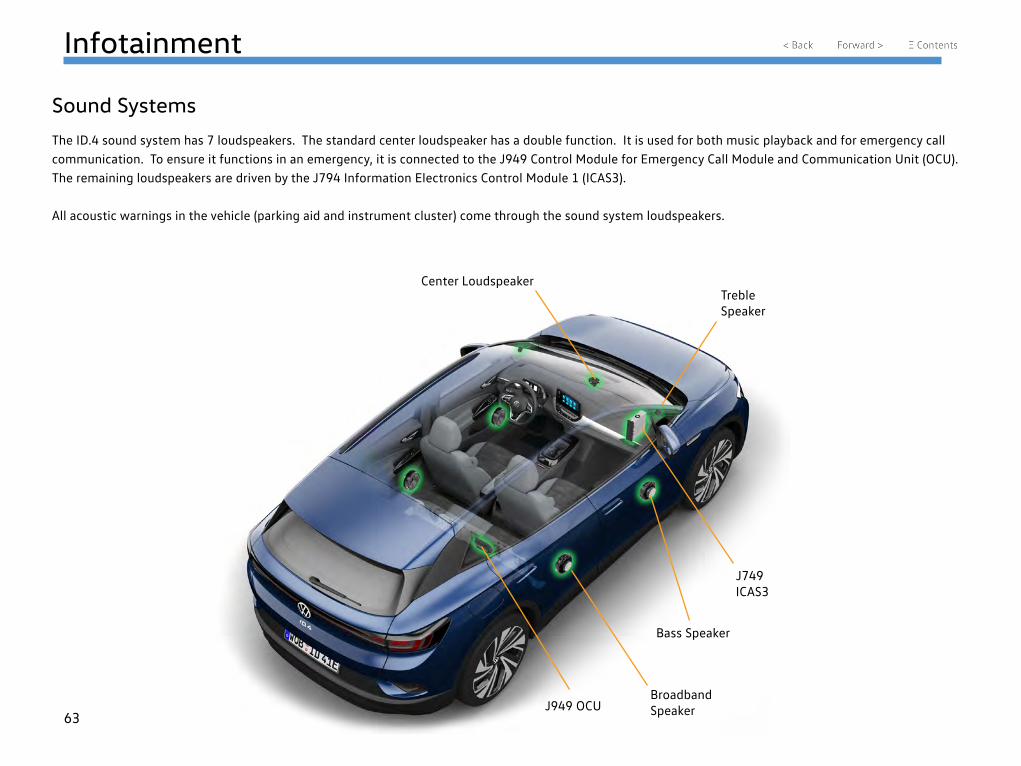
Sound Systems
The ID.4 sound system has 7 loudspeakers. The standard center loudspeaker has a double function. It is used for both music playback and for emergency call communication. To ensure it functions in an emergency, it is connected to the J949 Control Module for Emergency Call Module and Communication Unit (OCU). The remaining loudspeakers are driven by the J794 Information Electronics Control Module 1 (ICAS3).
All acoustic warnings in the vehicle (parking aid and instrument cluster) come through the sound system loudspeakers.
J949 OCUBroadband Speaker
Bass Speaker
J749 ICAS3
Treble Speaker
Center Loudspeaker
64
Infotainment
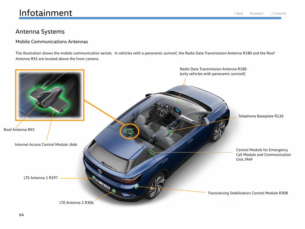
Antenna Systems
Mobile Communications Antennas
The illustration shows the mobile communication aerials. In vehicles with a panoramic sunroof, the Radio Data Transmission Antenna R180 and the Roof Antenna RX5 are located above the front camera.
Roof Antenna RX5
Internet Access Control Module J666
Telephone Baseplate R126
Radio Data Transmission Antenna R180 (only vehicles with panoramic sunroof)
Control Module for Emergency Call Module and Communication Unit J949
Transceiving Stabilization Control Module R308
LTE Antenna 2 R306
LTE Antenna 1 R297
65
Infotainment
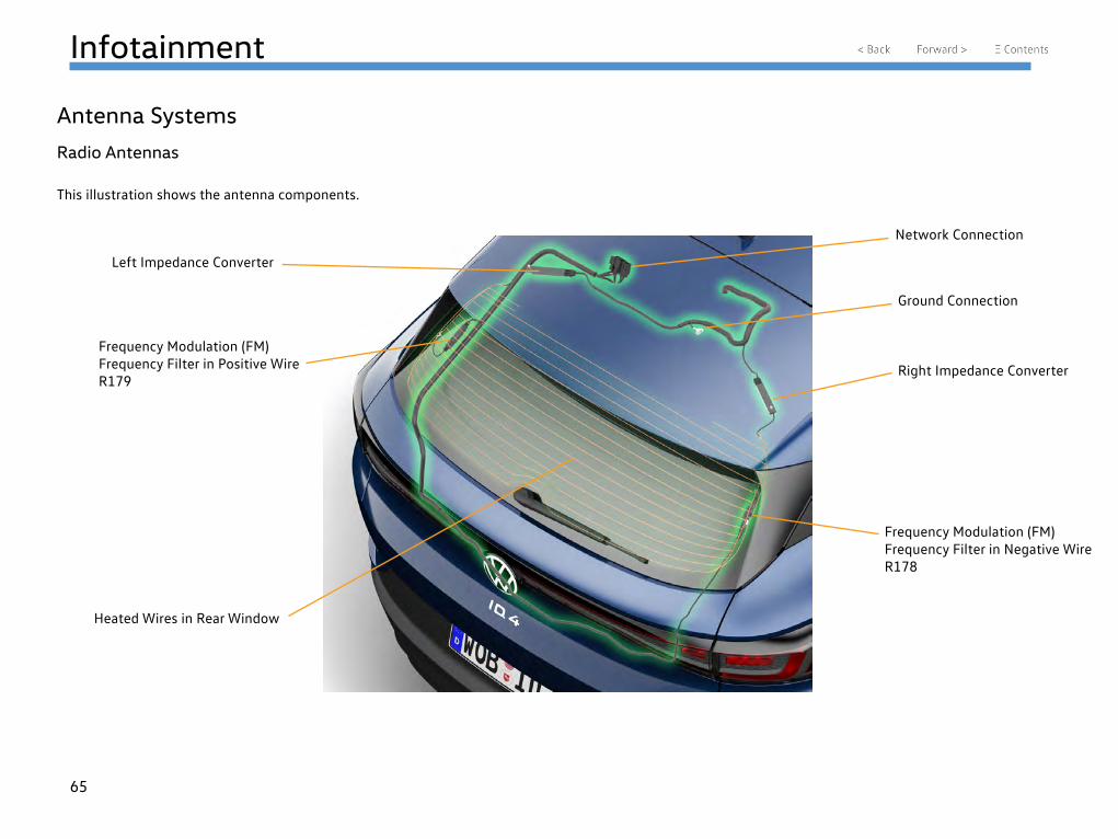
Antenna Systems
Radio Antennas
This illustration shows the antenna components.
Left Impedance Converter
Right Impedance Converter
Frequency Modulation (FM) Frequency Filter in Negative Wire R178
Frequency Modulation (FM) Frequency Filter in Positive Wire R179
Heated Wires in Rear Window
Ground Connection
Network Connection
Volkswagen Group Canada777 Bayly St W, Ajax, ON L1S 7G7September 2021